US7472051B2 - Dependable microcontroller, method for designing a dependable microcontroller and computer program product therefor - Google Patents
Dependable microcontroller, method for designing a dependable microcontroller and computer program product thereforDownload PDFInfo
- Publication number
- US7472051B2 US7472051B2US10/888,355US88835504AUS7472051B2US 7472051 B2US7472051 B2US 7472051B2US 88835504 AUS88835504 AUS 88835504AUS 7472051 B2US7472051 B2US 7472051B2
- Authority
- US
- United States
- Prior art keywords
- fault
- processing unit
- microcontroller
- central processing
- modules
- Prior art date
- Legal status (The legal status is an assumption and is not a legal conclusion. Google has not performed a legal analysis and makes no representation as to the accuracy of the status listed.)
- Active, expires
Links
Images


Classifications
- G—PHYSICS
- G06—COMPUTING OR CALCULATING; COUNTING
- G06F—ELECTRIC DIGITAL DATA PROCESSING
- G06F11/00—Error detection; Error correction; Monitoring
- G06F11/22—Detection or location of defective computer hardware by testing during standby operation or during idle time, e.g. start-up testing
- G06F11/26—Functional testing
- G06F11/27—Built-in tests
Definitions
- the present inventionrelates to techniques for achieving dependability in microcontrollers units (microcontroller) and was developed by paying specific attention to the possible use in automotive systems.
- microcontrollersare systems for anti blocking systems (ABS), torque control system (TCS) and automatic stability control (TSC).
- ABSanti blocking systems
- TCStorque control system
- TSCautomatic stability control
- microcontrollerin the following description should be intended in a broad sense, i.e., a System On a Chip (SOC) comprising analog to digital and digital to analog converters, CPU and CPU peripherals, memories, system buses, internal or external sensors and/or transducers, controls, instrumentations, output devices.
- SOCSystem On a Chip
- the present inventionalso relates to techniques and corresponding computer program products for the design of dependable microcontrollers.
- Such microelectronic systemsare based on central processing units and interconnected using robust networks, provided with means for the detection of faults.
- Such robust networksremove the need for thousands of costly and unreliable wires and connectors, used to make up a wiring loom.
- a ‘failure’the event that occurs when the delivered service of a system deviates from the specified service. It is called ‘error’ the part of the system state which is liable to lead to failure. The phenomenological cause of the error is called the ‘fault’.
- System dependabilityis defined as the quality of the delivered service such that reliance can justifiably be placed on this service.
- fault-toleranceby itself does not solve the dependability needs of a complex system.
- a fault-tolerant systemcould not be fail-safe.
- robustnessdefined as the ability of a system to continue to function despite the existence of faults in its component subsystems or parts, even if system performance may be diminished or otherwise altered—but always in a safe way—until the faults are corrected.
- a fault-robust systemwill keep its function even with changes in internal structure or external-environment.
- the solutions known from the prior artprovide for hardening the fabrication technology, so that is less prone to radiation-induced soft errors, or for introducing redundancy: at gate level, for example by implementing triple flip-flop structures with majority voting (N-modular redundancy); or at CPU level, for example by introducing some coding in the logic units of the processor; or at microcontroller level, for example by using multiple processors running in step with watchdogs; or at software level, for example by using multiple software threads, or a mixture of all of the above techniques.
- Redundancy at CPU levelis less expensive in terms of area overhead, but it requires CPU redesigning.
- a functional comparison moduleis coupled to the primary processing unit and to the secondary processing unit for comparing a primary output of the primary processing unit and a secondary output of the secondary processing unit to detect a fault if the primary output does not match the secondary output.
- Functional comparisonis performed by analyzing signatures of the outputs.
- Signaturesare computed in idle cycles or are obtained as results of test sequences or are determined on the basis of external address and data buses of the CPU itself, so that only a limited visibility of the content of the CPU is available. This very often results in inefficient signatures from the point of view of fault coverage and memory occupation, and in a greater latency of error detection.
- Dynamic redundancy techniquesare also known that require only the processor plus a fault detector that can identify faulty behavior of the processor. Such techniques allows for a higher utilization of computing resources, but they could generate a greater latency, because of the greater number of computations required to achieve good fault coverage.
- the most common solutions in this caseconsist in watchdogs or very simple fault detectors monitoring the data and address bus only to compute simple consistency checks.
- the CPU itselfis charged to handle part of the dependability issues, interacting with a simple external controller: in U.S. Pat. No. 5,436,837, a microcomputer and a monitoring module are disclosed.
- the monitoring moduleis preferably configured as a gate-array which executes a sequence control of the microcomputer. The monitoring module determines the correct or defective operation of the microcomputer from a comparison of the results of this processing.
- One of the goals of the present inventionis thus to provide a microcontroller that achieves high dependability, while making proper use of computing resources and circuit size.
- the present inventionis achieved by means of a dependable microcontroller having the characteristics set forth in the claims that follow.
- the inventionalso relates to a corresponding method for designing a dependable microcontroller, as well as to a computer program product directly loadable in the memory of a digital computer and comprising software code portions for performing the methods of the invention when the product is run on a computer.
- the solution according to the inventionprovides a microcontroller that contains a fault tolerant processing unit for validating operation of the central processing unit.
- the fault tolerant processing unitimplements also a distributed fault tolerant detection method on the chip through suitable interfaces and fault tolerant hardware blocks.
- a method for designing the system comprising the fault tolerant processing unit, interfaces and hardware blocksis also provided.
- the proposed solutionreduces the area overhead required on the chip, allows low latency control of the fault in the central processing unit and it is fully and flexibly customizable according to the System On Chip and user needs.
- FIG. 1shows a block diagram of the microcontroller of the invention
- FIG. 2shows a block diagram of a detail of the microcontroller of FIG. 1 ;
- FIG. 3shows a block diagram representing a further embodiment of the microcontroller of the invention
- FIG. 4shows a further detail of the microcontroller of FIG. 1 , related to an hardware verification component
- FIG. 5shows a further detail of the hardware verification component shown in FIG. 4 ;
- FIG. 6shows a block diagram pertaining to a design procedure of the microcontroller of FIG. 1 ;
- FIG. 7shows a block diagram representing a fault injection procedure used in the design procedure of FIG. 6 .
- microcontrollerin order to have a fault-robust systems, hardware redundancy is implemented, controlled and configured by software in order to achieve fault tolerance of complex CPU-based system on a chip without compromising execution time and code dimensions and with an acceptable hardware overhead.
- the microcontroller according to the inventionimplements distributed fault-tolerant techniques in every part of the system to be monitored, through suitable circuitry that is demanded to watching a particular problem and communicating with a central fault-tolerant processor, that is external and different from the central processing unit, i.e., it is not a dual central processing unit and it has autonomous computing resources external to that of said central processing unit.
- a central fault-tolerant processorcoordinates all the peripherals and keeps track of the fault-history of the system.
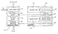
- FIG. 1a block diagram is shown representing the hardware architecture of a microcontroller 10 .
- Such a microcontroller 10basically comprises a processor 50 , that can be for instance a RISC unit like an ARM processor, comprising a central processing unit core 51 , associated to a coprocessor 52 .
- the processor 50comprises also a data memory module 64 , instruction cache memories 65 and a AMBA (Advanced Microcontroller Bus Architecture bus interface) interface 66 .
- a CPU system bus 53is provided for connecting the processor 50 with an interfaces module 61 , comprising among others a general purpose input/output interface, a serial parallel interface, a real time clock, a UART, timers and watchdogs. These interfaces are indicated collectively with reference 69 .
- vector interrupt controller 68is shown, connected to the CPU system bus 53 .
- Such a CPU bus system 53also allows communication with a set of peripherals 62 .
- a set of peripherals 62comprises application specific peripherals 55 , analog interfaces 56 , bus interfaces 57 , a direct memory access (DMA) module 58 , an external bus interface 59 , an embedded memory 60 .
- the interfaces module 61 and the set of peripherals 62also include suitable peripheral buses 63 , interconnecting their different devices.
- the microcontroller 10further comprises a Fault-Recognition Accelerator 11 , that is a processor operating as the main fault-manager.
- a Fault-Recognition Accelerator 11that is a processor operating as the main fault-manager.
- FRACFault-Recognition Accelerator
- Such a Fault-Recognition Accelerator 11is composed by a plurality of user-configurable modules for implementing different fault-detection and fault-tolerance techniques. Fault-recognition Accelerator 11 and related modules and peripherals are indicated in dashed line in FIG. 1 for easier identification.
- the Fault-Recognition Accelerator 11is placed, in the processor 50 , in communication with the central processing unit core 51 .
- the Fault-Recognition Accelerator 11operates in association with a Fault Recognition Memory 12 , also placed in the processor 50 , that can be a dedicated memory or a part of the CPU memory with dedicated ports.
- the Fault Recognition Memory 12stores data, such as code, historical tracks and other data needed by the Fault-Recognition Accelerator 11 to implement its functions.
- the Fault Recognition Accelerator 11comprises different modules, and it is dedicated to survey the overall system and the other fault-tolerant peripherals through the system bus 53 and other dedicated signals.
- the Fault-Recognition Accelerator 11is also responsible for start-up and periodic system built-in tests.
- Fault Recognition Accelerator 11can be accessed both through the processor core 51 , a JTAG port of the system and also directly through bus interfaces, in order to allow fast diagnostic and maintainability at system level.
- the Fault Recognition Accelerator 11In order to attain full dependability the Fault Recognition Accelerator 11 is able to generate fault alarms and events, like an exception, a program retry or a system stop, due to a fault in the central processing unit 51 or a fault in the Fault Recognition Accelerator 11 itself.
- the Fault Recognition Accelerator 11must be always able to react to these problems and avoid unsafe system conditions.
- Fault-Tolerant Memory interfaces 13are also provided on the microcontroller 10 , for interfacing with memories such as data memory 64 , cache memories 65 comprised in the processor 50 , the embedded memory 60 and the DMA module 58 comprised in the set of peripherals 62 .
- Faul-Tolerant Memory interfaces 13are composed by various user-configurable modules implementing different memory fault-detection and fault-tolerance techniques like Error Correction Code (ECC), Built-In Self Repair (BISR), and so on.
- ECCError Correction Code
- BISRBuilt-In Self Repair
- a Fault-Tolerant bus interface controller 14is provided for the protection of bus such the peripheral bus 63 or of the CPU system bus 53 or other-external buses such CAN bus.
- the microcontroller 10also comprises a Remote Fault Recognition Accelerator 16 , associated to the Application Specific Peripherals 55 , that is a special processor for application specific safety requirements.
- the Fault Recognition Accelerator 11 associated to the Fault-Recognition Compilerexploits a mixed “data and circuit-oriented” instead than a pure “circuit-oriented” fault protection mechanism, i.e., the protection is firstly applied to part of the system and part of the data that are relevant for the application. This relevant part is identified both by the user itself in the process of designing the System on Chip, as it will be detailed with reference to FIG. 6 , and by the Fault Recognition Compiler 111 through some techniques of code analysis as it will be detailed with reference to FIG. 7 .
- the Fault Recognition Accelerator 11thus comprises:
- CPU Generic Modules 23which are modules needed to process data arriving from Fault Recognition Accelerator/CPU interface modules 24 and to exchange data with the main protection modules.
- CPU Generic Modules 23are slightly CPU dependent, i.e., basic algorithms are CPU independent, however the way the data are processed can change with the CPU family.
- Fault Recognition Accelerator/CPU interface modules 24which are modules needed to exchange data with the CPU core 51 and the CPU system bus 53 . Modules 24 are CPU dependent.
- RISC processorssuch ARM processor
- RISC processorsare strongly based on register operations, i.e., each data transfer is carried out through one of the internal registers of the CPU.
- a set of registers of the Fault Recognition Accelerator 11is used as shadow copy of the processor 50 registers, and an extended visibility of these registers is obtained either using, if the extended core visibility needed to implement the first one is not available, a hardware FRAC module called Fault Recognition Accelerator-Core interface or a Fault Recognition Accelerator-Core software Interface, that will be detailed in describing modules 21 to 24 .
- the Fault Recognition Accelerator 11will monitor the code execution flow. In particular, it will real-time compute and check the branch-free block signatures and it will real-time compare the executed program flow with the reference, either stored in the Fault Recognition Memory 12 or embedded in the user code by the compiler 111 .
- This approachwill allow covering code faults, regardless their hardware location (memory or CPU).
- the Fault Recognition Accelerator 11will try (if possible) to repair the fault, restarting the execution flow from the last fault-free block (retry). Therefore, from the point of view of Fault Recognition Accelerator 11 , at the beginning of each block, the Fault Recognition Accelerator will recognize the starting signature and it will store this signature in an internal register for the run-time computing.
- the Fault Recognition Accelerator 11 in the proposed microcontrolleralso implements a data processing legality check procedure.
- Previous code and flow signature mechanismallow the coverage of code faults: it catches misinterpreted data, erroneous calculations, transient or permanent faults that cause any differences of the code execution flow with a very high coverage due to the use of the operation code as signature seed.
- this error detection mechanismcan be further enhanced by adding protection on critical variables of the application running on the processor.
- the most important variables of the application codecan be selected and coupled with either:
- the same data processing legality checkis performed by the hardware verification components 15 for variables living outside the CPU core and for signals exchanged with the external world.
- Fault Recognition Accelerator 11checks legal values for a given address (Legal absolute, delta and context value) based on register to memory visible data transfers. When a mismatch is detected, an exception is generated. This is also performed in multi-process applications: based again on register to memory visible data transfers, Fault Recognition Accelerator 11 is able to performs checks on the memory accesses made by the various tasks, especially when virtual addressing is not used. More in detail, in case a task performs an access to non-shared or other tasks regions, an exception is generated.
- a concurrent mode/interrupt check procedureis also implemented.
- the Fault Recognition Accelerator 11verifies flags and CPU mode signals, and on the basis of shadow Registers contents decides if the proper mode is set or not. When a mismatch is detected, an exception is generated. The same check is performed with interrupts, i.e., if interrupts were generated when not allowed or the opposite.
- the Initialization software Modules 112contain the code needed to initialize the Fault Recognition Accelerator 11 with respect to the system.
- the Operative System Interaction software Modules 113that are needed to interact with the Operative System, comprise an Operative System Driver Software Module containing the code needed to configure Fault Recognition Accelerator 11 with some Operating System runtime settings, such as the addresses where an image is mapped at runtime, dynamic Process ID. Furthermore, the module comprises some code possibly needed by the operating system to read Fault Recognition Accelerator fault status, as well as other statistic values. This interaction is to release Fault Recognition Accelerator status information to the Operative System.
- the proposed design procedurecomprises a fault-injection method for testing the fault tolerance of the system with respect to a specified behavior, i.e., injecting faults in the design to validate and assess the fault-robustness of the designed system.
- System definition 302 , system partitioning and simulation 303 at highest levelare performed in SimuLink/Matlab environment, whereas ECU design 305 , ECU verification 306 and system simulation/fault-injection 307 steps are performed in the proposed design and verification procedure.
- ECU design 305ECU design 305
- ECU verification 306system simulation/fault-injection 307 steps
- special Faults Packages 405are realized-with advanced radiation effect fault models (SEU package), typical fault models for bus protocols (BUS package, with CAN, OCP, AMBA faults), faults for standard digital (CPU package, with APB/AHB slaves), advanced memories configurations (MEM package, with Flash, D-RAM), ARM package with fault models for ARM processors (i.e., with models to insert faults in instructions through the modification of the correspondent micro-code), and so on.
- SEU packageadvanced radiation effect fault models
- BUS packagetypical fault models for bus protocols
- BUS packagewith CAN, OCP, AMBA faults
- faults for standard digitalCPU package, with APB/AHB slaves
- MEM packageadvanced memories configurations
- ARM package with fault models for ARM processorsi.e., with models to insert faults in instructions through the modification of the correspondent micro-code
- Fault-List generator 407is a pre-processor that is included to generate the fault list and collapse it based on static and dynamic collapsing algorithms, to reduce simulation time. User is also able to control parts of the system to be injected and add extra constraints for the fault list generation.
- Test Generator 403is able to generate the workload for device-oriented fault-injection or more in general to increase the fault coverage of a mission-oriented fault-injection covering the part of the device under test not covered by the mission workload.
- IEC 61508 Checker 408is included to allow the injection of standard faults defined by the IEC 61508 norm (such as faults for Bus, CPU, clocks, and so on) and the analysis of fault effects based on IEC 61508 safety integrity levels requirements).
- the present inventionis applicable not only in safety-critical systems (such as automotive, aerospace and biomedics) but also in reliability or availability critical systems such high-speed communications or advanced multimedia systems.
- the present inventionis not limited to a particular kind of faults.
- the inventionis addressing either:
Landscapes
- Engineering & Computer Science (AREA)
- General Engineering & Computer Science (AREA)
- Theoretical Computer Science (AREA)
- Computer Hardware Design (AREA)
- Quality & Reliability (AREA)
- Physics & Mathematics (AREA)
- General Physics & Mathematics (AREA)
- Debugging And Monitoring (AREA)
- Test And Diagnosis Of Digital Computers (AREA)
- Hardware Redundancy (AREA)
- Microcomputers (AREA)
Abstract
Description
- allow hardware and software standardization;
- be adaptable at the customer's needs;
- generate clean codes & scripts in a well defined flow;
- be easily linkable with the operating system;
- allow easy verification of sub-blocks and custom blocks;
- be upgradeable.
- scalability in a fast and easy way;
- to give verification detail and allow customizability of the verification;
- to be fault-robust and allow fault-injection in early stage (both for design and verification);
- Reliability: the probability, quantified in MTTF (Mean Time To Failure) that a piece of equipment or component will perform its intended function satisfactorily for a prescribed time and under specified environmental conditions;
- Availability: the probability, quantified by MTTR/MTTF (Mean Time To Repair) that the system will be functioning correctly at any given time;
- Safety: the freedom from undesired and unplanned event that results (at least) in a specific level or loss (i.e., accidents).
- fault-avoidance, that provides for avoiding faults by design;
- fault-removal, that provides for reducing the presence of faults, by verification. In this method fault-injection techniques are fundamental;
- fault-tolerance, a technique that provides correct operation despite presence of faults;
- fault-forecasting or fault-evasion, that provides for estimating, by evaluation, the presence, the creation and the consequences of faults and taking pre-emptive steps to stop the fault from occurring.
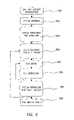
- microcontroller fault-forecasting at power-on: a sequence of BIST tests, or BISTs, run by the
Fault Recognition Accelerator 11 after power-on. Such BISTs are self-consistent software run in theFault Recognition Accelerator 11 or in a piece of dedicated hardware therein and they are focused either to cover the highest percentage of the functionality under test or to cover only the core functionalities needed by the real application. A BIST sequence performed by theFault Recognition Accelerator 11, substantially comprises a Built In Self Test on the RAM of theFault Recognition Accelerator 11, that is performed after power-on through its embedded Fault-tolerant Memory Interfaces13. Then a Built In Self Test on theFault Recognition Accelerator 11 is performed. Subsequently, validation passes on theCPU core 51 and a CPU RAM Built In Self Test is performed through Fault-tolerant Memory Interfaces13. Then in a Built In Self Test on theCPU core 51 is performed. Subsequently, fault-tolerant peripherals are validated through dedicatedhardware Verification Components 15. Then a BIST operation is performed on the bus interfaces through dedicated fault-tolerant bus interface 14. Finally external BIST operations are launched, to reach a ‘System Ok’ condition, if all above steps are successfully passed; - microcontroller on-line fault-forecasting: it is a subset of previously described BISTs executed during the system runtime. The microcontroller on-line self-test is run in two ways:
- during idle times, by isolating the block to be tested (e.g., the CPU or the RAM or one of the peripherals) by the rest of the system saving the current state, then by running the correspondent BIST and finally restoring the initial state;
- during normal operation, the Fault Recognition Compiler can be allowed to insert (for instance during loops), extra dummy codes in order to do in parallel active-tests in part of the CPU currently not used.
- on-line fault tolerance: it is a set of techniques for detecting faults during normal operation and taking actions when a fault is found, including data shadowing, code and flow signature, data processing legality check, addressing legality check, ALU concurrent integrity checking and concurrent mode/interrupt check.
- microcontroller fault-forecasting at power-on: a sequence of BIST tests, or BISTs, run by the
- a block signature, i.e., a signature of all the op-codes contained in each branch-free block. This signature is computed by the compiler by coding the operating codes of the instructions contained in the block by using self-consistent non-overlapping codes;
- a control-flow regular expression. During compile time, a Control Flow Graph is computed and therefore information about allowed path respect previous block are included in each signature.
- Legal Absolute values (i.e., maximum and minimum allowed values) that are checked by
Fault Recognition Accelerator 11 during runtime execution; - Legal Delta values, evaluated with respect to the previous operation on the same variable. In such a way, the result of each single operation carried out by ALU or MAC can be run-time checked against the set of allowed values, and in the case of an error, the operation can be repeated or the execution stopped;
- Legal Context values, i.e., timeframe and processes/tasks in which these variables can be read/written.
- Legal Absolute values (i.e., maximum and minimum allowed values) that are checked by
- a Global Supervisor Module that is the main controller and scheduler, for all the
Fault Recognition Accelerator 11 activities, for instance the scheduling of BISTs sequence ofFIG. 3 . It also contains all the Fault Recognition Accelerator status and configuration information, to be shared with the Operative System and User Application code through theCPU system bus 53; - a Program Watchdog Module that is composed by a watchdog triggered both by events inserted by the user into the software application and by time-windowed events automatically inserted by the Fault
Recognition Accelerator Compiler 111 itself. For the events inserted by the FaultRecognition Accelerator Compiler 111, the timeout event is computed taking into account expected timings limits (upper and lower). A timeout event generates an exception of this module for the Global Supervisor Module and to a Safe State Module, described in the following; - Fault Recognition Accelerator-Peripheral Manager Module, that is a module that manages all the interfaces of the peripherals of the
Fault Recognition Accelerator 11, e.g., the interfaces ofhardware Verification Components 15. When an error is detected in theCPU core 51, peripherals can be placed in a safe state configured at compile-time, or when an error is detected in the peripherals, the Global Supervisor Module and the Safe State Module are informed; - FRAC to FRAC Module that is a module needed when additional system fault-detection is a requirement or if multi-Fault Recognition Accelerator architectures are performed. Such a module comprises substantially a block that interfaces the internal
Fault Recognition Accelerator 11 with an external Fault Recognition Adcelerator (for hierarchical fault-robust systems or dual redundant systems as inFIG. 3 ) or with an external watchdog to have an additional protection in case of Fault Recognition Accelerator faults; - Debug-If Manager Module that manages all the data transfer from
Fault Recognition Accelerator 11 to the external world for debug purposes, through a JTAG or IS09141 interface. - Fault Recognition Accelerator-Memory Manager Module that manages all the interactions memory between the
Fault Recognition Accelerator 11 and-theFault recognition Memory 12. - Clock Supervisor Module, that is a module comprising a clock guardian fed by an independent clock source. By way of example, this module can be implemented by counting the number of system clocks contained in a period of a slow clock oscillator, that can be internal or external to the
Fault recognition accelerator 11 and the guardian is able to detect the degradation of the main clock during a fixed time window, i.e., if the clock is greater or lower of pre-determined safety levels. A timeout event generates an exception of this module for the Global Supervisor Module, and the slow clock is used to clock the Safe State Module to drive the system toward a fail-safe state; - Power Supervisor Module, that is a module composed by a scheduler that receives both from an external Power Supply Level Detector and from the Global Supervisor Module a signal specifying the need of a safe power-up or power-down. When enabled, it starts the Safe State Module and then provides a safe procedure to switch-on (power-up) or switch-off (power-down) the resets and clocks of the system. During the switch-off this module can also activate an external secondary power unit.
- a Global Supervisor Module that is the main controller and scheduler, for all the
- Shadow Variable Module that makes a copy of the critical variables used by the application and updates such variables based on register to/from memory visible data transfers (Load/Store instructions). The shadow variable module compares memory to register transfers with the mismatches. When a mismatch is detected, an exception is generated for the Global Supervisor Module, the Safe State Module and the Data Retry Module, either hardware or software. The shadow variable modules can be configured via software to select variables to be protected.
- Legal Variable Module, that is a module checking legal values for a given variable (Legal absolute, delta and context value) based on register to/from memory visible data transfers (Load/Store instructions) When a mismatch is detected, an exception is generated for the Global Supervisor Module and the Safe State Module. Legal variable module can be configured by software to select variables to be protected and values for the legal values;
- Code&Flow Signature Module, that is a module, based on the code and flow signatures computed in compilation time by the Fault
Recognition Accelerator Compiler 111, and stored in theFault Recognition Memory 12 or embedded in the user code memory, and based on code and flow signatures computed run-time by their module itself using the runtime instruction code. This module is able to detect faults in the CPU program flow. Furthermore, the module is able to detect faults in inline literals when they are loaded in theCPU core 51. When a mismatch is detected, an exception is generated for the Global Supervisor Module, the Safe State Module and the Program Retry Module; - Safe State Module, that, when triggered by a software signal, or by the Global Supervisor Module, or by other modules as described above, is able to start a procedure to bring the system to a safe-state, i.e., by putting safe values in the variables, stopping the
CPU 51, sending a signal to the Fault Recognition Accelerator-Peripheral Manager Module to put all the peripherals ofFault Recognition Accelerator 11 in a safe state. It is configured at compile time; - Shadow Register Module, that makes a copy of the register bank of the CPU, and updates it based on memory to register visible data transfers (Load/Store instructions) and based on the access to the ALU Write pbrt available from Fault Recognition Accelerator-Core Interface Module. Then the shadow register module compares final register to memory transfers with the contents of the internal copy, detecting mismatches. When a mismatch is detected between internal results and the one on the ALU write port, an exception is generated for the Global Supervisor Module, the Safe State Module and the Data Retry. This module can be configured by software to select register to be protected;
- Legal Load-Store Unit (LSU) Module, that is a module for checking legal values for a delta value, space and time context value) based on register to memory visible data transfers (Load/Store instructions). When a mismatch is detected, an exception is generated for the Global Supervisor Module and the Safe State Module. This module can be configured by software to select addresses to be protected and value for the legal values;
- Task Supervisor Module, used in multi-process applications. Based on register to memory visible data transfers (Load/Store instructions), it is able to performs checks on the memory accesses made by the various tasks, especially when virtual addressing is not used. More in detail, in case a task performs an access to non-shared or others generated for the Global Supervisor Module, the Safe State Module and the Program Retry Module;
- Data Retry Module, used when, besides fault-detection, also fault-correction is needed. Based on the results of the Shadow Variable or Shadow Register Module or Legal Variable Module, it is able to restore the value of a faulty variables/registers in the memories, by using the CPU ports, or by interacting with the Data Retry software module;
- Prog Retry Module, used when besides fault-detection is needed also fault-correction. Based on the results of the Code&Flow Signature Module, it is able to restore the CPU state and program counter, by using the CPU ports or by interacting with the Program Retry Module;
- Opcode Decode Module that is the generic module that decodes op-codes read from an interface between
Fault Recognition Accelerator 11 and theCoprocessor 52 and from Fault Recognition Accelerator ETM (Embedded Trace Module) interface, and provides the decoded control signal to the other modules; - Exc/Int Supervisor Module, that is a module for continuously checking if the issued interrupts and exceptions are valid and served, considering the memory map configuration (access permissions, alignment and unaligned accesses etc.) and the interrupt requests. Furthermore it detects if an exception was supposed to be raised (for instance due to an user access to privileged areas) but it is not. If a fault is detected an exception is generated for the Global Supervisor Module and the Safe State Module;
- Mode/Flag Supervisor Module, that verifies flags and CPU mode, based on Shadow Register Module and Fault Recognition Accelerator Software Register Shadowing Module, and based on signals coming from the CPU. When a mismatch is detected, an exception is generated for the Fault Recognition Accelerator Global Supervisor and the Fault Recognition Accelerator Safe State Module;
- Boundary Supervisor Module, that continuously compares addresses, data and control signals generated by the Load-Store Unit (LSU) with the CPU memory boundaries, not checked by other modules, in order to detect faults in the units in between. When a mismatch is detected, an exception is generated for the Global Supervisor Module and the Safe State Module;
- ALU/MAC Supervisor Module, that makes a reduced copy of the CPU Integer Core, including most critical ALU/MAC operations implemented on coded values (e.g., operating on module-three numbers). It has access to the Shadow Register Module and checks results detected on the ALU write port of the core, obtained through the Fault Recognition Accelerator-Core interface. When a mismatch is detected between internal results and the one on the ALU write port, an exception is generated for the Global Supervisor Module and the Safe State Module. If fault-detection is needed on operations not implemented in this reduced module, they can be decomposed in safe instructions by the Fault
Recognition Accelerator Compiler 111; - Coprocessor Supervisor Module, based on the Shadow Register Module, checks if the data transferred from the CPU registers to the coprocessor is valid or not. When a mismatch is detected, an exception is generated for the Global Supervisor Module and the Safe State Module;
- BIST Supervisor Module that, when triggered by a software signal, or by the Global Supervisor Module, or by the Power Supervisor module, is able to start a BIST (Built In self Test) of the
CPU core 51 or part of it. When a mismatch is detected, an exception is generated for the Global Supervisor Module and the Safe State Module; - Instruction Prediction Module, that is an advanced module carrying out a sort of a cache storing recent part of codes executed by the
CPU core 51, comparing with the current program flow and detecting differences. When a mismatch is detected, an exception is generated for the Global Supervisor Module, the Safe State Module, the Program Retry Module (Hardware or Software).
- Opcode Decode Module that is the generic module that decodes op-codes read from an interface between
- Fault Recognition Accelerator-INT module, that interfaces
Fault Recognition Accelerator 11 with the CPU interrupt lines; - Fault Recognition Accelerator-COPROC interface module interfaces Fault Recognition Accelerator with the
CPU Coprocessor 52 interface; - Fault Recognition Accelerator-Embedded Trace Module (ETM) Interface, that interfaces Fault Recognition Accelerator with the CPU core ETM Interface;
- Fault Recognition Accelerator-Boundary Interface that interfaces
Fault Recognition Accelerator 11 with theCPU buses - Fault Recognition Accelerator-Core interface, that interfaces Fault Recognition Accelerator with the CPU Integer Core to give extended hardware visibility (such as the visibility of the ALU Write port for the register shadowing, and so on).
- Fault Recognition Accelerator-INT module, that interfaces
- Base Configuration Software Module containing the code needed to configure the
Fault Recognition Accelerator 11 with respect to the Operative System and the Application User Code; - Signature Configuration Software Module, containing the code needed to configure the Fault Recognition Accelerator with the code&flow signatures computed at compile time by Fault
Recognition Accelerator Compiler 111.
- Base Configuration Software Module containing the code needed to configure the
- EXC/INT Supervisor Software Module, that is the software counter-part for the hardware Exc/Int Supervisor Module;
- CPU Supervisor Software Module, that contains the code needed to verify the processor configuration (block settings, memory mapping etc.). If a fault is detected, the module is able to restore the program flow as the Program Retry Module;
- Task Supervisor Software Module, that is the software counter-part for the Task Supervisor Module;
- Fault Recognition Accelerator-Core Software Interface is composed by code that mimics at software level what Fault Recognition Accelerator-Core Interface does at hardware level. In particular, when necessary, copies of the internal core registers are made into the
Fault Recognition Accelerator 11; - Coprocessor Supervisor Software, that is the software counter-part for the hardware Coprocessor Supervisor Module;
- BIST Supervisor Software Module, that is the software counter part for the hardware BIST Supervisor Module;
- Data Retry Software Module, that is the software counterpart for the hardware Data Retry Module;
- Program Retry Software Module that is the software counterpart for hardware Program Retry Module.
- a Fault Recognitor F-RAM Module, that wraps an external memory and code its contents in order to carry out an on-line Built-In Self Test and if needed on-line Built-In Self Repair;
- a Fault Recognitor F-ROM Module that wraps an external memory and code its contents in order to carry out an on-line Built-In Self Test and if needed on-line ‘Built-In Self Repair’;
- Fault Recognition F-DMA Module, that comprises a block that wraps the external memory DMA controller in order to check for address and data faults.
- AHB Module that uses a redundant coded AHB bus in order to check data transmitted on the main AHB (Advanced High-performance Bus) bus like the
bus system 53; - APB Module, that uses a redundant coded APB bus in order to check data transmitted on the main APB (Advanced Peripheral Bus) bus, like
peripheral bus 63; - CAN Module that implements extra levels of fault-detection and correction for CAN bus modules.
- AHB Module that uses a redundant coded AHB bus in order to check data transmitted on the main AHB (Advanced High-performance Bus) bus like the
Expect@A_rise=>{[1.3];@B:rise} else PHY_error
- a set of hVC base modules, that are detailed with reference to
FIG. 5 ; - an hVC library of precompiled hardware verification components for standard blocks such PWM, timers and so on.
- a set of hVC base modules, that are detailed with reference to
- a Hardware
Verification Checker Module 604, that embodies the hardware-verification checking unit of theHardware verification block 15 for a given interface; - a Hardware
Verification BIST Module 605, that embodies the hardware-verification BIST unit of thehardware Verification Component 15 for a given interface; - a Hardware
Verification Interface Module 601, performing a safe connection between theFault Recognition Accelerator 11 and thehardware Verification Components 15, receiving configurations values, providingFault Recognition Accelerator 11 with go/no-go signals, receiving commands fromFault Recognition Accelerator 11, interacting with the Fault Recognition Peripherals Manager Module; - a Hardware Verification-
Manager Module 602, that is the manager of the wholehardware Verification Component 15, and it is the responsible for putting the controlled interface in a safe state when needed; - Hardware Verification-
MUX Module 603 that is a safe multiplexer structure used to select between system signal, for instance,central processing unit 51, andhardware Verification Components 15 signals; - a Hardware Verification-Configuration software Module that implements at compile time or design time all the needed features to configure the modules of
hardware Verification Components 15, e.g., selecting/ordering legal-delta-context checking for the interfaces, etc. This module is part of the Initialization Software Modules previously described for theFault Recognition Compiler 111.
- a Hardware
- a set of eVC components for the platform components. Using these building blocks more complex eVC can be composed in order to verify system-level aspects;
- a CPU verification procedure. It is mainly composed by a constraint-driven test generator, that generates corner-case instruction sequences based both on user constraints and feedback from the coverage analyzer;
- a fault injector implemented using the capabilities of SpecMan Elite;
- a database of typical system situations, in particular automotive system situations, such as: multi-processor CAN/TTP units, fault models, and so on.
- step301 represents taking in account specifications;
- step302 represents system definition;
- step303 represents system partitioning and simulation;
- step304 represents fault-tolerance system definition;
- step305 represents ECU design;
- step306 represents ECU verification;
- step307 represents system verification with fault injection;
- step308 represents final implementation.
- Fault Tolerance System Definition304: this step can be performed both at RTOS (Real-Time Operating System) and system level starting in the SimuLink environment by using standard Hazard Analysis techniques, such as Software Failure Modes and Effects Analysis or others. Then, when basic needs are defined, such as for instance definition of fail-silent or fail-safe behaviors, these choices can be implemented at ECU design level within the design procedure, by defining for instance the level of
Fault Recognition Accelerator 11 hardware/software integration for each of the system components, the dimension of the FaultRecognition Accelerator memory 12, and so on.
- Fault Tolerance System Definition304: this step can be performed both at RTOS (Real-Time Operating System) and system level starting in the SimuLink environment by using standard Hazard Analysis techniques, such as Software Failure Modes and Effects Analysis or others. Then, when basic needs are defined, such as for instance definition of fail-silent or fail-safe behaviors, these choices can be implemented at ECU design level within the design procedure, by defining for instance the level of
- System Verification with Fault-injection307: the complete system can be verified against faults and the fault-tolerance choices can be validated at the system level.
- basic “bit-level” models such stuck-at, open line, indetermination, short, bridging, glitches and bit-flips;
- basic memory fault models (SRAM, ROM, and so on);
- faults in the clock/power lines;
- extension of “bit-level” fault models at higher-level of abstraction (e.g., pure behavior), such variable faults, branches/cases conditions mutants, and so on.
- mechanical faults, i.e., due to deterioration (wear, fatigue, corrosion) or shock (fractures, striction, overload), as soon as they cause an electronic fault in the system;
- Electronic faults, i.e., due to latent manufacturing defects (stuck-at in hidden part of the circuit), or to the operating environment (radiation, noise, heat, ESD, electro-migration), as soon as they are detected by the fault-detection mechanisms and, concerning design defects, as soon as they cause either an illegal execution-flow and/or an illegal operating code processing and/or an illegal values of critical variables, respect to the application code;
- Software faults (including the ones in the Compiler), i.e., design defects or “code rot” (e.g., accumulated run-time faults), if they cause either an illegal execution-flow and/or an illegal operating code processing and/or an illegal values of critical variables, respect to the application code. Software faults are also detected if they cause illegal transitions in peripherals.
Claims (30)
Applications Claiming Priority (2)
| Application Number | Priority Date | Filing Date | Title |
|---|---|---|---|
| EP03015860AEP1496435A1 (en) | 2003-07-11 | 2003-07-11 | Dependable microcontroller, method for designing a dependable microcontroller and computer program product therefor |
| EP03015860.4 | 2003-07-11 |
Publications (2)
| Publication Number | Publication Date |
|---|---|
| US20050050387A1 US20050050387A1 (en) | 2005-03-03 |
| US7472051B2true US7472051B2 (en) | 2008-12-30 |
Family
ID=33442788
Family Applications (1)
| Application Number | Title | Priority Date | Filing Date |
|---|---|---|---|
| US10/888,355Active2026-02-28US7472051B2 (en) | 2003-07-11 | 2004-07-09 | Dependable microcontroller, method for designing a dependable microcontroller and computer program product therefor |
Country Status (3)
| Country | Link |
|---|---|
| US (1) | US7472051B2 (en) |
| EP (1) | EP1496435A1 (en) |
| JP (2) | JP4999262B2 (en) |
Cited By (45)
| Publication number | Priority date | Publication date | Assignee | Title |
|---|---|---|---|---|
| US20040153672A1 (en)* | 2002-11-18 | 2004-08-05 | Arm Limited | Switching between secure and non-secure processing modes |
| US20050244007A1 (en)* | 2004-04-30 | 2005-11-03 | Little Herbert A | System and method for securing data |
| US20070150756A1 (en)* | 2005-12-23 | 2007-06-28 | Nagracard S.A. | Secure system-on-chip |
| US20070226572A1 (en)* | 2005-11-07 | 2007-09-27 | Ming Zhang | Soft error rate analysis system |
| US20070234072A1 (en)* | 2005-12-23 | 2007-10-04 | Nagracard S.A. | Secure system-on-chip |
| US20070287135A1 (en)* | 2006-04-20 | 2007-12-13 | Sungkyunkwan University Foundation For Corporate Collaboration | 3d vehicle simulator system and simulation method for ecu embedded system |
| US20070294574A1 (en)* | 2006-06-05 | 2007-12-20 | Dmp Electronics Inc. | Dual computer for system backup and being fault-tolerant |
| US20080059016A1 (en)* | 2006-08-31 | 2008-03-06 | Mayhew William R | Distributed arithmetic logic unit security check |
| US20080255813A1 (en)* | 2004-06-05 | 2008-10-16 | Shai Fine | Probabilistic regression suites for functional verification |
| US20090106489A1 (en)* | 2007-10-22 | 2009-04-23 | Himax Technologies Limited | Data processing apparatus with shadow register and method thereof |
| US20100083203A1 (en)* | 2008-10-01 | 2010-04-01 | International Business Machines Corporation | Modeling System-Level Effects of Soft Errors |
| US20100115255A1 (en)* | 2008-11-03 | 2010-05-06 | Jim Vito | System and Method of Dynamically Building a Behavior Model on a Hardware System |
| US20100281134A1 (en)* | 2009-03-31 | 2010-11-04 | Melen Roger D | Architecture for a self-healing computer system |
| US20110209021A1 (en)* | 2008-02-06 | 2011-08-25 | Steen Ditlev Sorensen | Failure Detection and Mitigation in Logic Circuits |
| US8645897B1 (en)* | 2013-01-07 | 2014-02-04 | Freescale Semiconductor, Inc. | Integrated circuit design verification system |
| US8656191B2 (en) | 2005-12-23 | 2014-02-18 | Nagravision S.A. | Secure system-on-chip |
| US8683400B1 (en)* | 2012-11-21 | 2014-03-25 | Cadence Design Systems, Inc. | System and method for fault sensitivity analysis of mixed-signal integrated circuit designs |
| US20140217406A1 (en)* | 2013-02-01 | 2014-08-07 | Scaleo Chip | Apparatus and Method for Non-Intrusive Random Memory Failure Emulation Within an Integrated Circuit |
| US8813004B1 (en) | 2012-11-21 | 2014-08-19 | Cadence Design Systems, Inc. | Analog fault visualization system and method for circuit designs |
| US8863050B1 (en) | 2013-03-15 | 2014-10-14 | Cadence Design Systems, Inc. | Efficient single-run method to determine analog fault coverage versus bridge resistance |
| US8868989B2 (en) | 2012-07-12 | 2014-10-21 | Freescale Semiconductor, Inc. | System for testing error detection circuits |
| US8875077B1 (en) | 2014-02-10 | 2014-10-28 | Cadence Design Systems, Inc. | Fault sensitivity analysis-based cell-aware automated test pattern generation flow |
| US8949101B2 (en) | 2011-10-12 | 2015-02-03 | International Business Machines Corporation | Hardware execution driven application level derating calculation for soft error rate analysis |
| US8996348B1 (en) | 2012-11-21 | 2015-03-31 | Cadence Design Systems, Inc. | System and method for fault sensitivity analysis of digitally-calibrated-circuit designs |
| US20150121323A1 (en)* | 2013-10-24 | 2015-04-30 | International Business Machines Corporation | Determining a quality parameter for a verification environment |
| US9052887B2 (en) | 2010-02-16 | 2015-06-09 | Freescale Semiconductor, Inc. | Fault tolerance of data processing steps operating in either a parallel operation mode or a non-synchronous redundant operation mode |
| US20160062331A1 (en)* | 2014-08-27 | 2016-03-03 | Freescale Semiconductor, Inc. | Apparatus and method for validating the integrity of control signals in timing domain |
| EP3016010A1 (en) | 2014-10-31 | 2016-05-04 | Yogitech S.p.A. | Method, system and program for measuring the effect of microscopic hardware faults in applications implemented in hardware |
| US9372772B1 (en)* | 2015-03-27 | 2016-06-21 | Cavium, Inc. | Co-verification—of hardware and software, a unified approach in verification |
| US9437057B2 (en) | 2013-08-20 | 2016-09-06 | Komatsu Ltd. | Construction machine controller |
| US9506982B2 (en) | 2014-11-14 | 2016-11-29 | Cavium, Inc. | Testbench builder, system, device and method including a generic monitor and transporter |
| US20160380858A1 (en)* | 2015-06-23 | 2016-12-29 | Fts Computertechnik Gmbh | Distributed real-time computer system and method for forcing fail-silent behavior of a distributed real-time computer system |
| US9582251B2 (en)* | 2014-11-14 | 2017-02-28 | Cavium, Inc. | Algorithm to achieve optimal layout of decision logic elements for programmable network devices |
| US9823983B2 (en) | 2014-09-25 | 2017-11-21 | Nxp Usa, Inc. | Electronic fault detection unit |
| US9842014B2 (en) | 2012-11-22 | 2017-12-12 | Nxp Usa, Inc. | Data processing device, method of execution error detection and integrated circuit |
| US20180350773A1 (en)* | 2015-11-30 | 2018-12-06 | Pezy Computing K.K. | Die and package, and manufacturing method for die and producing method for package |
| US10204698B2 (en) | 2016-12-20 | 2019-02-12 | Ampere Computing Llc | Method to dynamically inject errors in a repairable memory on silicon and a method to validate built-in-self-repair logic |
| US10282315B2 (en) | 2015-03-27 | 2019-05-07 | Cavium, Llc | Software assisted hardware configuration for software defined network system-on-chip |
| US10331529B2 (en) | 2017-03-15 | 2019-06-25 | International Business Machines Corporation | Maintaining system reliability in a CPU with co-processors |
| US20190250210A1 (en)* | 2018-02-09 | 2019-08-15 | Nxp Usa, Inc. | System Architecture Method and Apparatus for Adaptive Hardware Fault Detection with Hardware Metrics Subsystem |
| US10691634B2 (en) | 2015-11-30 | 2020-06-23 | Pezy Computing K.K. | Die and package |
| US10922203B1 (en)* | 2018-09-21 | 2021-02-16 | Nvidia Corporation | Fault injection architecture for resilient GPU computing |
| US11135975B2 (en)* | 2018-02-28 | 2021-10-05 | Komatsu Ltd. | Periphery monitoring device, work machine, periphery monitoring control method, and display device |
| US11408934B2 (en) | 2017-12-22 | 2022-08-09 | Nvidia Corporation | In system test of chips in functional systems |
| US12124346B2 (en)* | 2020-03-13 | 2024-10-22 | Nvidia Corporation | Leveraging low power states for fault testing of processing cores at runtime |
Families Citing this family (40)
| Publication number | Priority date | Publication date | Assignee | Title |
|---|---|---|---|---|
| DE10148032A1 (en)* | 2001-09-28 | 2003-04-24 | Bosch Gmbh Robert | Testing CPU of microprocessor or micro-controller, by checking gates of CPU that influence flow of computer program during self-test |
| JP4348950B2 (en)* | 2003-01-23 | 2009-10-21 | 株式会社デンソー | Electronic control unit |
| EP1800438A1 (en)* | 2004-10-14 | 2007-06-27 | Lagotek Corporation | Distributed wireless home and commercial electrical automation systems |
| US7321989B2 (en)* | 2005-01-05 | 2008-01-22 | The Aerospace Corporation | Simultaneously multithreaded processing and single event failure detection method |
| DE102006001872B4 (en)* | 2006-01-13 | 2013-08-22 | Infineon Technologies Ag | Apparatus and method for checking an error detection functionality of a data processing device for attacks |
| DE102006001873B4 (en)* | 2006-01-13 | 2009-12-24 | Infineon Technologies Ag | Apparatus and method for checking an error detection functionality of a memory circuit |
| DE102006045906A1 (en)* | 2006-09-28 | 2008-04-17 | Infineon Technologies Ag | Module with a controller for a chip card |
| US20080120189A1 (en)* | 2006-10-27 | 2008-05-22 | Mci, Llc. | Method and apparatus for providing workflow automation |
| JP4479743B2 (en)* | 2007-04-24 | 2010-06-09 | 株式会社デンソー | Rollback method and information processing apparatus |
| ATE502460T1 (en) | 2007-08-16 | 2011-04-15 | Nxp Bv | SYSTEM AND METHOD FOR PROVIDING ERROR DETECTION CAPABILITY |
| EP2220773B1 (en)* | 2007-12-06 | 2012-09-05 | Rambus Inc. | Edge-based loss-of-signal detection |
| US7890810B1 (en)* | 2008-02-26 | 2011-02-15 | Network Appliance, Inc. | Method and apparatus for deterministic fault injection of storage shelves in a storage subsystem |
| DE102008022620A1 (en)* | 2008-04-30 | 2009-11-05 | Mtu Aero Engines Gmbh | Engine control system and method for qualifying the components of the engine control system |
| US8683178B2 (en)* | 2011-01-21 | 2014-03-25 | Apple Inc. | Sharing a fault-status register when processing vector instructions |
| US8731765B2 (en)* | 2011-06-28 | 2014-05-20 | GM Global Technology Operations LLC | Method and apparatus for fault detection in a torque machine of a powertrain system |
| FR3005179B1 (en)* | 2013-04-25 | 2015-05-15 | Oberthur Technologies | METHOD AND SYSTEM FOR SIMULATING THE EFFECTS OF ATTACK ON A COMPUTER CODE |
| DE112013000204T5 (en)* | 2013-08-20 | 2015-06-25 | Komatsu Ltd. | Construction machine controller |
| CN104021054A (en)* | 2014-06-11 | 2014-09-03 | 浪潮(北京)电子信息产业有限公司 | Server fault visual detecting and processing method and system and programmable chip |
| DE102014213922B4 (en)* | 2014-07-17 | 2020-02-20 | Continental Automotive Gmbh | Vehicle infotainment system |
| JP6393628B2 (en)* | 2015-01-21 | 2018-09-19 | 日立オートモティブシステムズ株式会社 | Vehicle control device |
| KR20160098929A (en)* | 2015-02-11 | 2016-08-19 | 한국전자통신연구원 | Fast system availability measurement apparatus for system development and method thereof |
| KR102251991B1 (en) | 2015-05-14 | 2021-05-17 | 한국전자통신연구원 | Method and apparatus for fault injection and fault tolerance analysis |
| US10409657B2 (en)* | 2016-01-15 | 2019-09-10 | Google Llc | Identifiers across application instances |
| KR102018541B1 (en)* | 2016-03-09 | 2019-09-06 | 한국전자통신연구원 | System on chip comprising core controller and core management method thereof |
| KR102020994B1 (en)* | 2017-06-09 | 2019-09-16 | 슈어소프트테크주식회사 | Method and apparatus for fault injection test |
| US10831595B1 (en) | 2019-05-31 | 2020-11-10 | International Business Machines Corporation | Performing error detection during deterministic program execution |
| CN110308732B (en)* | 2019-07-25 | 2023-08-04 | 北京智行者科技股份有限公司 | Failure detection method of automatic driving controller and automatic driving controller |
| CN111176927A (en)* | 2019-11-26 | 2020-05-19 | 中盈创信(北京)科技有限公司 | Detection system and detection method for functional board card |
| US11422185B2 (en) | 2020-06-30 | 2022-08-23 | Nxp Usa, Inc. | System and method for testing critical components on system-on-chip |
| CN112181455B (en)* | 2020-09-24 | 2024-04-26 | 深圳数联天下智能科技有限公司 | Online upgrading method of microcontroller, microcontroller and storage medium |
| US11983100B2 (en) | 2020-09-29 | 2024-05-14 | Amazon Technologies, Inc. | Automated testing of systems and applications |
| CN112506517B (en)* | 2020-11-30 | 2024-09-06 | 飞腾信息技术有限公司 | Bare engine system-level excitation cross compiling system and compiling method |
| US11175340B1 (en) | 2021-02-15 | 2021-11-16 | Nxp B.V. | System and method for managing testing and availability of critical components on system-on-chip |
| EP4275123A1 (en)* | 2021-03-22 | 2023-11-15 | Huawei Technologies Co., Ltd. | Program flow monitoring for gateway applications |
| CN114048077A (en)* | 2021-10-31 | 2022-02-15 | 山东云海国创云计算装备产业创新中心有限公司 | A remote memory mapping detection system and server |
| CN115828590B (en)* | 2022-12-01 | 2025-08-05 | 西安电子科技大学 | A method for modeling and simulating processor radiation effects |
| CN116430827A (en)* | 2023-04-07 | 2023-07-14 | 北京轩宇空间科技有限公司 | Fault-tolerant verification system and method supporting software and hardware fault injection and voting |
| DE102024101827A1 (en) | 2024-01-23 | 2025-07-24 | Infineon Technologies Ag | TRIGGER FOR A SAFE CONDITION |
| CN118211277B (en)* | 2024-05-22 | 2024-08-09 | 山东航天人工智能安全芯片研究院 | Design circuit and design method of asymmetric encryption and decryption coprocessor |
| CN119718761A (en)* | 2025-02-28 | 2025-03-28 | 北京智芯微电子科技有限公司 | On-chip fault tolerance processing method, system, chip and electronic equipment |
Citations (19)
| Publication number | Priority date | Publication date | Assignee | Title |
|---|---|---|---|---|
| US5371742A (en)* | 1992-08-12 | 1994-12-06 | At&T Corp. | Table driven fault recovery system with redundancy and priority handling |
| US5557737A (en)* | 1994-06-13 | 1996-09-17 | Bull Hn Information Systems Inc. | Automated safestore stack generation and recovery in a fault tolerant central processor |
| US5574927A (en)* | 1994-03-25 | 1996-11-12 | International Meta Systems, Inc. | RISC architecture computer configured for emulation of the instruction set of a target computer |
| US5963167A (en)* | 1996-03-13 | 1999-10-05 | California Institute Of Technology | Analyzing system for global positioning system and general satellite tracking |
| US6081864A (en) | 1997-07-31 | 2000-06-27 | Advanced Micro Devices, Inc. | Dynamic configuration of a device under test |
| US6105148A (en)* | 1995-06-16 | 2000-08-15 | Lucent Technologies Inc. | Persistent state checkpoint and restoration systems |
| US6170078B1 (en)* | 1998-02-27 | 2001-01-02 | International Business Machines Corporation | Fault simulation using dynamically alterable behavioral models |
| US6233702B1 (en)* | 1992-12-17 | 2001-05-15 | Compaq Computer Corporation | Self-checked, lock step processor pairs |
| US6249893B1 (en) | 1998-10-30 | 2001-06-19 | Advantest Corp. | Method and structure for testing embedded cores based system-on-a-chip |
| US20020077782A1 (en)* | 1999-05-10 | 2002-06-20 | Fruehling Terry L. | Secured microcontroller architecture |
| US6421790B1 (en) | 1999-05-10 | 2002-07-16 | Delphi Technologies, Inc. | Method and circuit for analysis of the operation of a microcontroller using signature analysis of data and instructions |
| US6499123B1 (en)* | 1989-02-24 | 2002-12-24 | Advanced Micro Devices, Inc. | Method and apparatus for debugging an integrated circuit |
| US20030046666A1 (en) | 2001-08-11 | 2003-03-06 | Harry Siebert | Program-controlled unit |
| US20030217256A1 (en)* | 2002-05-17 | 2003-11-20 | Sun Microsystems, Inc. | Method and apparatus for disabling defective components in a computer system |
| US6691250B1 (en)* | 2000-06-29 | 2004-02-10 | Cisco Technology, Inc. | Fault handling process for enabling recovery, diagnosis, and self-testing of computer systems |
| US20040153672A1 (en)* | 2002-11-18 | 2004-08-05 | Arm Limited | Switching between secure and non-secure processing modes |
| US6819327B2 (en)* | 2001-05-18 | 2004-11-16 | Sun Microsystems, Inc. | Signature analysis registers for testing a computer graphics system |
| US20050028047A1 (en)* | 2003-07-30 | 2005-02-03 | Dehai Kong | Method and circuit for command integrity checking (CIC) in a graphics controller |
| US20050102567A1 (en)* | 2003-10-31 | 2005-05-12 | Mcguire Cynthia A. | Method and architecture for automated fault diagnosis and correction in a computer system |
Family Cites Families (19)
| Publication number | Priority date | Publication date | Assignee | Title |
|---|---|---|---|---|
| JPS55157042A (en)* | 1979-05-28 | 1980-12-06 | Toshiba Corp | Information processor |
| US4912707A (en)* | 1988-08-23 | 1990-03-27 | International Business Machines Corporation | Checkpoint retry mechanism |
| JPH03228138A (en)* | 1990-02-01 | 1991-10-09 | Nec Corp | Interruption processing system |
| JPH03256134A (en)* | 1990-03-06 | 1991-11-14 | Koufu Nippon Denki Kk | Checking circuit for vector computing element |
| JPH0777102A (en)* | 1993-09-03 | 1995-03-20 | Matsushita Electric Ind Co Ltd | In-vehicle electronic control unit |
| JPH0863374A (en)* | 1994-08-22 | 1996-03-08 | Toshiba Corp | LSI with built-in trace function |
| JP3716948B2 (en)* | 1996-04-19 | 2005-11-16 | 本田技研工業株式会社 | Automotive electronic control unit |
| JP3141787B2 (en)* | 1996-08-28 | 2001-03-05 | 日本電気株式会社 | Microcomputer |
| US5933614A (en)* | 1996-12-31 | 1999-08-03 | Compaq Computer Corporation | Isolation of PCI and EISA masters by masking control and interrupt lines |
| JP3036485B2 (en)* | 1997-09-12 | 2000-04-24 | 日本電気株式会社 | Real number operation method |
| JPH11338731A (en)* | 1998-05-21 | 1999-12-10 | Oki Electric Ind Co Ltd | Data processor |
| JP2000158724A (en)* | 1998-11-30 | 2000-06-13 | Fuji Xerox Co Ltd | Image-processing apparatus, image processing method and recording medium |
| JP2001060160A (en)* | 1999-08-23 | 2001-03-06 | Mitsubishi Heavy Ind Ltd | Cpu duplex system for controller |
| JP2002184948A (en)* | 2000-12-12 | 2002-06-28 | Hitachi Ltd | Method for manufacturing semiconductor integrated circuit device |
| JP4398102B2 (en)* | 2001-02-09 | 2010-01-13 | 富士通テン株式会社 | Automotive electronics |
| TW591378B (en)* | 2001-02-22 | 2004-06-11 | Hitachi Ltd | Memory test method, information recording medium and semiconductor integrated circuit |
| JP3514247B2 (en)* | 2001-05-09 | 2004-03-31 | 日本電気株式会社 | Communication line board inspection system |
| JP2003156542A (en)* | 2001-11-22 | 2003-05-30 | Hitachi Ltd | Test method and semiconductor device |
| DE10317650A1 (en)* | 2003-04-17 | 2004-11-04 | Robert Bosch Gmbh | Program-controlled unit and method |
- 2003
- 2003-07-11EPEP03015860Apatent/EP1496435A1/ennot_activeCeased
- 2004
- 2004-07-09USUS10/888,355patent/US7472051B2/enactiveActive
- 2004-07-12JPJP2004204737Apatent/JP4999262B2/ennot_activeExpired - Fee Related
- 2011
- 2011-11-14JPJP2011248216Apatent/JP5631848B2/ennot_activeExpired - Lifetime
Patent Citations (20)
| Publication number | Priority date | Publication date | Assignee | Title |
|---|---|---|---|---|
| US6499123B1 (en)* | 1989-02-24 | 2002-12-24 | Advanced Micro Devices, Inc. | Method and apparatus for debugging an integrated circuit |
| US5371742A (en)* | 1992-08-12 | 1994-12-06 | At&T Corp. | Table driven fault recovery system with redundancy and priority handling |
| US6233702B1 (en)* | 1992-12-17 | 2001-05-15 | Compaq Computer Corporation | Self-checked, lock step processor pairs |
| US5574927A (en)* | 1994-03-25 | 1996-11-12 | International Meta Systems, Inc. | RISC architecture computer configured for emulation of the instruction set of a target computer |
| US5557737A (en)* | 1994-06-13 | 1996-09-17 | Bull Hn Information Systems Inc. | Automated safestore stack generation and recovery in a fault tolerant central processor |
| US6105148A (en)* | 1995-06-16 | 2000-08-15 | Lucent Technologies Inc. | Persistent state checkpoint and restoration systems |
| US5963167A (en)* | 1996-03-13 | 1999-10-05 | California Institute Of Technology | Analyzing system for global positioning system and general satellite tracking |
| US6295021B1 (en)* | 1996-03-13 | 2001-09-25 | California Institute Of Technology | Techniques for monitoring and controlling yaw attitude of a GPS satellite |
| US6081864A (en) | 1997-07-31 | 2000-06-27 | Advanced Micro Devices, Inc. | Dynamic configuration of a device under test |
| US6170078B1 (en)* | 1998-02-27 | 2001-01-02 | International Business Machines Corporation | Fault simulation using dynamically alterable behavioral models |
| US6249893B1 (en) | 1998-10-30 | 2001-06-19 | Advantest Corp. | Method and structure for testing embedded cores based system-on-a-chip |
| US20020077782A1 (en)* | 1999-05-10 | 2002-06-20 | Fruehling Terry L. | Secured microcontroller architecture |
| US6421790B1 (en) | 1999-05-10 | 2002-07-16 | Delphi Technologies, Inc. | Method and circuit for analysis of the operation of a microcontroller using signature analysis of data and instructions |
| US6691250B1 (en)* | 2000-06-29 | 2004-02-10 | Cisco Technology, Inc. | Fault handling process for enabling recovery, diagnosis, and self-testing of computer systems |
| US6819327B2 (en)* | 2001-05-18 | 2004-11-16 | Sun Microsystems, Inc. | Signature analysis registers for testing a computer graphics system |
| US20030046666A1 (en) | 2001-08-11 | 2003-03-06 | Harry Siebert | Program-controlled unit |
| US20030217256A1 (en)* | 2002-05-17 | 2003-11-20 | Sun Microsystems, Inc. | Method and apparatus for disabling defective components in a computer system |
| US20040153672A1 (en)* | 2002-11-18 | 2004-08-05 | Arm Limited | Switching between secure and non-secure processing modes |
| US20050028047A1 (en)* | 2003-07-30 | 2005-02-03 | Dehai Kong | Method and circuit for command integrity checking (CIC) in a graphics controller |
| US20050102567A1 (en)* | 2003-10-31 | 2005-05-12 | Mcguire Cynthia A. | Method and architecture for automated fault diagnosis and correction in a computer system |
Non-Patent Citations (4)
| Title |
|---|
| Hocenski et al., "Influence of Software of Fault-Tolerant Microprocessor Control System Dependability," 1999 IEEE.* |
| IBM Corp., "Selective Software Update," IBM Technical Disclosure Bulletin 32(9B), Feb. 1990. |
| IBM Corp., "Selective Software Update," IBM Technical Disclosure Bulletin 32(9B):86, Feb. 1, 1990. |
| Madeira et al., "Towards a Framework for Dependability Benchmarking," EDCC4 2002.* |
Cited By (82)
| Publication number | Priority date | Publication date | Assignee | Title |
|---|---|---|---|---|
| US7849310B2 (en)* | 2002-11-18 | 2010-12-07 | Arm Limited | Switching between secure and non-secure processing modes |
| US20040153672A1 (en)* | 2002-11-18 | 2004-08-05 | Arm Limited | Switching between secure and non-secure processing modes |
| US20050244007A1 (en)* | 2004-04-30 | 2005-11-03 | Little Herbert A | System and method for securing data |
| US8130957B2 (en)* | 2004-04-30 | 2012-03-06 | Research In Motion Limited | System and method for securing data |
| US8761396B2 (en)* | 2004-04-30 | 2014-06-24 | Blackberry Limited | System and method for securing data for redirecting and transporting over a wireless network |
| US20120191978A1 (en)* | 2004-04-30 | 2012-07-26 | Little Herbert A | System and method for securing data for redirecting and transporting over a wireless network |
| US20080255813A1 (en)* | 2004-06-05 | 2008-10-16 | Shai Fine | Probabilistic regression suites for functional verification |
| US7865340B2 (en)* | 2004-06-05 | 2011-01-04 | International Business Machines Corporation | Probabilistic regression suites for functional verification |
| US20070226572A1 (en)* | 2005-11-07 | 2007-09-27 | Ming Zhang | Soft error rate analysis system |
| US8356188B2 (en)* | 2005-12-23 | 2013-01-15 | Nagravision S.A. | Secure system-on-chip |
| US8656191B2 (en) | 2005-12-23 | 2014-02-18 | Nagravision S.A. | Secure system-on-chip |
| US8181008B2 (en)* | 2005-12-23 | 2012-05-15 | Nagracard S.A. | Secure system-on-chip |
| US20070234072A1 (en)* | 2005-12-23 | 2007-10-04 | Nagracard S.A. | Secure system-on-chip |
| US20070150756A1 (en)* | 2005-12-23 | 2007-06-28 | Nagracard S.A. | Secure system-on-chip |
| US7869985B2 (en)* | 2006-04-20 | 2011-01-11 | Sungkyunkwan University Foundation For Corporate Collaboration | 3D vehicle simulator system and simulation method for ECU embedded system |
| US20070287135A1 (en)* | 2006-04-20 | 2007-12-13 | Sungkyunkwan University Foundation For Corporate Collaboration | 3d vehicle simulator system and simulation method for ecu embedded system |
| US7853824B2 (en)* | 2006-06-05 | 2010-12-14 | Dmp Electronics Inc. | Dual computer for system backup and being fault-tolerant |
| US20070294574A1 (en)* | 2006-06-05 | 2007-12-20 | Dmp Electronics Inc. | Dual computer for system backup and being fault-tolerant |
| US7933696B2 (en)* | 2006-08-31 | 2011-04-26 | GM Global Technology Operations LLC | Distributed arithmetic logic unit security check |
| US20080059016A1 (en)* | 2006-08-31 | 2008-03-06 | Mayhew William R | Distributed arithmetic logic unit security check |
| US8280940B2 (en)* | 2007-10-22 | 2012-10-02 | Himax Technologies Limited | Data processing apparatus with shadow register and method thereof |
| US20090106489A1 (en)* | 2007-10-22 | 2009-04-23 | Himax Technologies Limited | Data processing apparatus with shadow register and method thereof |
| US20110209021A1 (en)* | 2008-02-06 | 2011-08-25 | Steen Ditlev Sorensen | Failure Detection and Mitigation in Logic Circuits |
| US8117512B2 (en)* | 2008-02-06 | 2012-02-14 | Westinghouse Electric Company Llc | Failure detection and mitigation in logic circuits |
| US8091050B2 (en)* | 2008-10-01 | 2012-01-03 | International Business Machines Corporation | Modeling system-level effects of soft errors |
| US20100083203A1 (en)* | 2008-10-01 | 2010-04-01 | International Business Machines Corporation | Modeling System-Level Effects of Soft Errors |
| US20100115255A1 (en)* | 2008-11-03 | 2010-05-06 | Jim Vito | System and Method of Dynamically Building a Behavior Model on a Hardware System |
| US20100281134A1 (en)* | 2009-03-31 | 2010-11-04 | Melen Roger D | Architecture for a self-healing computer system |
| US8775886B2 (en)* | 2009-03-31 | 2014-07-08 | Toyota Jidosha Kabushiki Kaisha | Architecture for a self-healing computer system |
| US9052887B2 (en) | 2010-02-16 | 2015-06-09 | Freescale Semiconductor, Inc. | Fault tolerance of data processing steps operating in either a parallel operation mode or a non-synchronous redundant operation mode |
| US8949101B2 (en) | 2011-10-12 | 2015-02-03 | International Business Machines Corporation | Hardware execution driven application level derating calculation for soft error rate analysis |
| US8868989B2 (en) | 2012-07-12 | 2014-10-21 | Freescale Semiconductor, Inc. | System for testing error detection circuits |
| US9026963B1 (en)* | 2012-11-21 | 2015-05-05 | Cadence Design Systems, Inc. | System and method for fault sensitivity analysis of mixed-signal integrated circuit designs |
| US8683400B1 (en)* | 2012-11-21 | 2014-03-25 | Cadence Design Systems, Inc. | System and method for fault sensitivity analysis of mixed-signal integrated circuit designs |
| US8813004B1 (en) | 2012-11-21 | 2014-08-19 | Cadence Design Systems, Inc. | Analog fault visualization system and method for circuit designs |
| US8996348B1 (en) | 2012-11-21 | 2015-03-31 | Cadence Design Systems, Inc. | System and method for fault sensitivity analysis of digitally-calibrated-circuit designs |
| US9842014B2 (en) | 2012-11-22 | 2017-12-12 | Nxp Usa, Inc. | Data processing device, method of execution error detection and integrated circuit |
| US8645897B1 (en)* | 2013-01-07 | 2014-02-04 | Freescale Semiconductor, Inc. | Integrated circuit design verification system |
| US9275757B2 (en)* | 2013-02-01 | 2016-03-01 | Scaleo Chip | Apparatus and method for non-intrusive random memory failure emulation within an integrated circuit |
| US20140217406A1 (en)* | 2013-02-01 | 2014-08-07 | Scaleo Chip | Apparatus and Method for Non-Intrusive Random Memory Failure Emulation Within an Integrated Circuit |
| US8863050B1 (en) | 2013-03-15 | 2014-10-14 | Cadence Design Systems, Inc. | Efficient single-run method to determine analog fault coverage versus bridge resistance |
| US9437057B2 (en) | 2013-08-20 | 2016-09-06 | Komatsu Ltd. | Construction machine controller |
| US20150121323A1 (en)* | 2013-10-24 | 2015-04-30 | International Business Machines Corporation | Determining a quality parameter for a verification environment |
| US9443044B2 (en)* | 2013-10-24 | 2016-09-13 | International Business Machines Corporation | Determining a quality parameter for a verification environment |
| US8875077B1 (en) | 2014-02-10 | 2014-10-28 | Cadence Design Systems, Inc. | Fault sensitivity analysis-based cell-aware automated test pattern generation flow |
| US20160062331A1 (en)* | 2014-08-27 | 2016-03-03 | Freescale Semiconductor, Inc. | Apparatus and method for validating the integrity of control signals in timing domain |
| US9823983B2 (en) | 2014-09-25 | 2017-11-21 | Nxp Usa, Inc. | Electronic fault detection unit |
| EP3016010A1 (en) | 2014-10-31 | 2016-05-04 | Yogitech S.p.A. | Method, system and program for measuring the effect of microscopic hardware faults in applications implemented in hardware |
| US9898379B2 (en) | 2014-10-31 | 2018-02-20 | Intel Corporation | Method for measuring the effect of microscopic hardware faults in high-complexity applications implemented in a hardware electronic system, and corresponding system and computer program product |
| US9864583B2 (en)* | 2014-11-14 | 2018-01-09 | Cavium, Inc. | Algorithm to derive logic expression to select execution blocks for programmable network devices |
| US10082538B2 (en) | 2014-11-14 | 2018-09-25 | Cavium, Inc. | Testbench builder, system, device and method |
| US9778315B2 (en) | 2014-11-14 | 2017-10-03 | Cavium, Inc. | Testbench builder, system, device and method having agent loopback functionality |
| US9817067B2 (en) | 2014-11-14 | 2017-11-14 | Cavium, Inc. | Testbench builder, system, device and method including latency detection |
| US9547041B2 (en) | 2014-11-14 | 2017-01-17 | Cavium, Inc. | Testbench builder, system, device and method with phase synchronization |
| US9836283B2 (en)* | 2014-11-14 | 2017-12-05 | Cavium, Inc. | Compiler architecture for programmable application specific integrated circuit based network devices |
| US9582251B2 (en)* | 2014-11-14 | 2017-02-28 | Cavium, Inc. | Algorithm to achieve optimal layout of decision logic elements for programmable network devices |
| US9864582B2 (en)* | 2014-11-14 | 2018-01-09 | Cavium, Inc. | Code processor to build orthogonal execution blocks for programmable network devices |
| US9506982B2 (en) | 2014-11-14 | 2016-11-29 | Cavium, Inc. | Testbench builder, system, device and method including a generic monitor and transporter |
| US9864584B2 (en)* | 2014-11-14 | 2018-01-09 | Cavium, Inc. | Code generator for programmable network devices |
| US9870204B2 (en)* | 2014-11-14 | 2018-01-16 | Cavium, Inc. | Algorithm to achieve optimal layout of instruction tables for programmable network devices |
| US10466976B2 (en)* | 2014-11-14 | 2019-11-05 | Cavium, Llc | Compiler architecture for programmable application specific integrated circuit based network devices |
| US10006963B2 (en) | 2014-11-14 | 2018-06-26 | Cavium, Inc. | Packet tracking in a verification environment |
| US10282315B2 (en) | 2015-03-27 | 2019-05-07 | Cavium, Llc | Software assisted hardware configuration for software defined network system-on-chip |
| US9372772B1 (en)* | 2015-03-27 | 2016-06-21 | Cavium, Inc. | Co-verification—of hardware and software, a unified approach in verification |
| US20160380858A1 (en)* | 2015-06-23 | 2016-12-29 | Fts Computertechnik Gmbh | Distributed real-time computer system and method for forcing fail-silent behavior of a distributed real-time computer system |
| US10397081B2 (en)* | 2015-06-23 | 2019-08-27 | Tttech Auto Ag | Distributed real-time computer system and method for forcing fail-silent behavior of a distributed real-time computer system |
| US20180350773A1 (en)* | 2015-11-30 | 2018-12-06 | Pezy Computing K.K. | Die and package, and manufacturing method for die and producing method for package |
| US10818638B2 (en)* | 2015-11-30 | 2020-10-27 | Pezy Computing K.K. | Die and package |
| US10691634B2 (en) | 2015-11-30 | 2020-06-23 | Pezy Computing K.K. | Die and package |
| US10204698B2 (en) | 2016-12-20 | 2019-02-12 | Ampere Computing Llc | Method to dynamically inject errors in a repairable memory on silicon and a method to validate built-in-self-repair logic |
| US10331529B2 (en) | 2017-03-15 | 2019-06-25 | International Business Machines Corporation | Maintaining system reliability in a CPU with co-processors |
| US10339015B2 (en) | 2017-03-15 | 2019-07-02 | International Business Machines Corporation | Maintaining system reliability in a CPU with co-processors |
| US11408934B2 (en) | 2017-12-22 | 2022-08-09 | Nvidia Corporation | In system test of chips in functional systems |
| US11726139B2 (en) | 2017-12-22 | 2023-08-15 | Nvidia Corporation | In-system test of chips in functional systems |
| US12078678B2 (en) | 2017-12-22 | 2024-09-03 | Nvidia Corporation | In system test of chips in functional systems |
| US10495691B2 (en)* | 2018-02-09 | 2019-12-03 | Nxp Usa, Inc. | System architecture method and apparatus for adaptive hardware fault detection with hardware metrics subsystem |
| US20190250210A1 (en)* | 2018-02-09 | 2019-08-15 | Nxp Usa, Inc. | System Architecture Method and Apparatus for Adaptive Hardware Fault Detection with Hardware Metrics Subsystem |
| US11135975B2 (en)* | 2018-02-28 | 2021-10-05 | Komatsu Ltd. | Periphery monitoring device, work machine, periphery monitoring control method, and display device |
| US10922203B1 (en)* | 2018-09-21 | 2021-02-16 | Nvidia Corporation | Fault injection architecture for resilient GPU computing |
| US20220156169A1 (en)* | 2018-09-21 | 2022-05-19 | Nvidia Corporation | Fault injection architecture for resilient gpu computing |
| US11669421B2 (en)* | 2018-09-21 | 2023-06-06 | Nvidia Corporation | Fault injection architecture for resilient GPU computing |
| US12124346B2 (en)* | 2020-03-13 | 2024-10-22 | Nvidia Corporation | Leveraging low power states for fault testing of processing cores at runtime |
Also Published As
| Publication number | Publication date |
|---|---|
| JP4999262B2 (en) | 2012-08-15 |
| JP2012074057A (en) | 2012-04-12 |
| US20050050387A1 (en) | 2005-03-03 |
| JP5631848B2 (en) | 2014-11-26 |
| EP1496435A1 (en) | 2005-01-12 |
| JP2005050329A (en) | 2005-02-24 |
Similar Documents
| Publication | Publication Date | Title |
|---|---|---|
| US7472051B2 (en) | Dependable microcontroller, method for designing a dependable microcontroller and computer program product therefor | |
| JP2005050329A5 (en) | ||
| Bernardi et al. | Development flow for on-line core self-test of automotive microcontrollers | |
| Bernardi et al. | A new hybrid fault detection technique for systems-on-a-chip | |
| Portela-García et al. | On the use of embedded debug features for permanent and transient fault resilience in microprocessors | |
| Kohn et al. | Architectural concepts for fail-operational automotive systems | |
| Löfwenmark et al. | Fault and timing analysis in critical multi-core systems: A survey with an avionics perspective | |
| Bellotti et al. | How future automotive functional safety requirements will impact microprocessors design | |
| Bas et al. | SafeDE: A low-cost hardware solution to enforce diverse redundancy in multicores | |
| Scherer et al. | Trace and debug port based watchdog processor | |
| Mariani et al. | A flexible microcontroller architecture for fail-safe and fail-operational systems | |
| Ghadhab et al. | Is software coded processing an answer to the execution integrity challenge of current and future automotive software-intensive applications? | |
| Lari et al. | Providing fault tolerance through invasive computing | |
| Lisboa et al. | Online hardening of programs against SEUs and SETs | |
| Sini et al. | Improving Software Reliability with Rust: Implementation for Enhanced Control Flow Checking Methods | |
| Brewerton et al. | Implementation of a Basic Single-Microcontroller Monitoring Concept for Safety Critical Systems on a Dual-Core Microcontroller | |
| Schneider et al. | Basic single-microcontroller monitoring concept for safety critical systems | |
| Reinbacher et al. | A runtime verification unit for microcontrollers | |
| Di Carlo et al. | A fpga-based reconfigurable software architecture for highly dependable systems | |
| Sini et al. | A Novel Approach to Address Random Hardware Failures for Automotive Application Within the ISO26262 and AUTOSAR Frameworks | |
| Mariani et al. | Cost-effective approach to error detection for an embedded automotive platform | |
| Rajabzadeh et al. | A dependable microcontroller-based embedded system | |
| Hoppe | Real-time trace decoding and monitoring for safety and security in embedded systems | |
| Alcaide Portet | Hardware/Software solutions to enable the use of high-performance processors in the most stringent safety-critical systems | |
| Oho et al. | Virtualization: System-Level Fault Simulation of SRAM Errors in Automotive Electronic Control Systems |
Legal Events
| Date | Code | Title | Description |
|---|---|---|---|
| AS | Assignment | Owner name:YOGITECH SPA, ITALY Free format text:ASSIGNMENT OF ASSIGNORS INTEREST;ASSIGNORS:MARIANI, RICCARDO;MOTTO, SILVANO;CHIAVACCI, MONIA;REEL/FRAME:015354/0385 Effective date:20040902 | |
| STCF | Information on status: patent grant | Free format text:PATENTED CASE | |
| FEPP | Fee payment procedure | Free format text:PAYOR NUMBER ASSIGNED (ORIGINAL EVENT CODE: ASPN); ENTITY STATUS OF PATENT OWNER: LARGE ENTITY | |
| FPAY | Fee payment | Year of fee payment:4 | |
| FPAY | Fee payment | Year of fee payment:8 | |
| FEPP | Fee payment procedure | Free format text:PAYER NUMBER DE-ASSIGNED (ORIGINAL EVENT CODE: RMPN); ENTITY STATUS OF PATENT OWNER: LARGE ENTITY Free format text:PAYOR NUMBER ASSIGNED (ORIGINAL EVENT CODE: ASPN); ENTITY STATUS OF PATENT OWNER: LARGE ENTITY | |
| SULP | Surcharge for late payment | ||
| AS | Assignment | Owner name:INTEL CORPORATION, CALIFORNIA Free format text:ASSIGNMENT OF ASSIGNORS INTEREST;ASSIGNOR:YOGITECH, S.P.A.;REEL/FRAME:042568/0677 Effective date:20170518 | |
| MAFP | Maintenance fee payment | Free format text:PAYMENT OF MAINTENANCE FEE, 12TH YEAR, LARGE ENTITY (ORIGINAL EVENT CODE: M1553); ENTITY STATUS OF PATENT OWNER: LARGE ENTITY Year of fee payment:12 | |
| AS | Assignment | Owner name:TAHOE RESEARCH, LTD., IRELAND Free format text:ASSIGNMENT OF ASSIGNORS INTEREST;ASSIGNOR:INTEL CORPORATION;REEL/FRAME:061175/0176 Effective date:20220718 |