US7470274B2 - Single-blow shockwave generation device - Google Patents
Single-blow shockwave generation deviceDownload PDFInfo
- Publication number
- US7470274B2 US7470274B2US10/545,107US54510705AUS7470274B2US 7470274 B2US7470274 B2US 7470274B2US 54510705 AUS54510705 AUS 54510705AUS 7470274 B2US7470274 B2US 7470274B2
- Authority
- US
- United States
- Prior art keywords
- chamber
- gas
- duct
- bore
- piston
- Prior art date
- Legal status (The legal status is an assumption and is not a legal conclusion. Google has not performed a legal analysis and makes no representation as to the accuracy of the status listed.)
- Expired - Lifetime, expires
Links
- 238000007789sealingMethods0.000claimsabstractdescription50
- 238000009825accumulationMethods0.000claimsabstractdescription11
- CURLTUGMZLYLDI-UHFFFAOYSA-NCarbon dioxideChemical compoundO=C=OCURLTUGMZLYLDI-UHFFFAOYSA-N0.000claimsdescription10
- 230000033001locomotionEffects0.000claimsdescription6
- 239000012530fluidSubstances0.000claimsdescription5
- 238000000034methodMethods0.000claimsdescription4
- 229910002092carbon dioxideInorganic materials0.000claimsdescription3
- 239000001569carbon dioxideSubstances0.000claimsdescription3
- 230000006837decompressionEffects0.000claimsdescription3
- 238000004891communicationMethods0.000claims4
- 230000008878couplingEffects0.000claims1
- 238000010168coupling processMethods0.000claims1
- 238000005859coupling reactionMethods0.000claims1
- 238000011144upstream manufacturingMethods0.000claims1
- 239000004575stoneSubstances0.000abstractdescription12
- 230000035939shockEffects0.000abstractdescription7
- 230000002485urinary effectEffects0.000abstractdescription3
- 230000006378damageEffects0.000abstractdescription2
- 238000001356surgical procedureMethods0.000abstractdescription2
- 239000007789gasSubstances0.000description58
- 239000007787solidSubstances0.000description6
- 208000009911Urinary CalculiDiseases0.000description5
- 239000012634fragmentSubstances0.000description4
- 239000002775capsuleSubstances0.000description3
- 230000008030eliminationEffects0.000description3
- 238000003379elimination reactionMethods0.000description3
- IJGRMHOSHXDMSA-UHFFFAOYSA-NAtomic nitrogenChemical compoundN#NIJGRMHOSHXDMSA-UHFFFAOYSA-N0.000description2
- 230000001955cumulated effectEffects0.000description2
- 238000013016dampingMethods0.000description2
- 238000006073displacement reactionMethods0.000description2
- 230000000694effectsEffects0.000description2
- 210000003734kidneyAnatomy0.000description2
- 230000003902lesionEffects0.000description2
- 238000004519manufacturing processMethods0.000description2
- 238000003303reheatingMethods0.000description2
- 210000000626ureterAnatomy0.000description2
- 238000005406washingMethods0.000description2
- 230000015572biosynthetic processEffects0.000description1
- 239000001273butaneSubstances0.000description1
- 230000006835compressionEffects0.000description1
- 238000007906compressionMethods0.000description1
- 230000000994depressogenic effectEffects0.000description1
- 230000005489elastic deformationEffects0.000description1
- 238000001839endoscopyMethods0.000description1
- 238000000605extractionMethods0.000description1
- 238000013467fragmentationMethods0.000description1
- 238000006062fragmentation reactionMethods0.000description1
- 230000000977initiatory effectEffects0.000description1
- 239000007788liquidSubstances0.000description1
- IJDNQMDRQITEOD-UHFFFAOYSA-Nn-butaneChemical compoundCCCCIJDNQMDRQITEOD-UHFFFAOYSA-N0.000description1
- OFBQJSOFQDEBGM-UHFFFAOYSA-Nn-pentaneNatural productsCCCCCOFBQJSOFQDEBGM-UHFFFAOYSA-N0.000description1
- 229910052757nitrogenInorganic materials0.000description1
- 238000000926separation methodMethods0.000description1
- 125000006850spacer groupChemical group0.000description1
- 208000008281urolithiasisDiseases0.000description1
Images


Classifications
- A—HUMAN NECESSITIES
- A61—MEDICAL OR VETERINARY SCIENCE; HYGIENE
- A61B—DIAGNOSIS; SURGERY; IDENTIFICATION
- A61B17/00—Surgical instruments, devices or methods
- A61B17/22—Implements for squeezing-off ulcers or the like on inner organs of the body; Implements for scraping-out cavities of body organs, e.g. bones; for invasive removal or destruction of calculus using mechanical vibrations; for removing obstructions in blood vessels, not otherwise provided for
- A61B17/22004—Implements for squeezing-off ulcers or the like on inner organs of the body; Implements for scraping-out cavities of body organs, e.g. bones; for invasive removal or destruction of calculus using mechanical vibrations; for removing obstructions in blood vessels, not otherwise provided for using mechanical vibrations, e.g. ultrasonic shock waves
- A61B17/22012—Implements for squeezing-off ulcers or the like on inner organs of the body; Implements for scraping-out cavities of body organs, e.g. bones; for invasive removal or destruction of calculus using mechanical vibrations; for removing obstructions in blood vessels, not otherwise provided for using mechanical vibrations, e.g. ultrasonic shock waves in direct contact with, or very close to, the obstruction or concrement
- A—HUMAN NECESSITIES
- A61—MEDICAL OR VETERINARY SCIENCE; HYGIENE
- A61B—DIAGNOSIS; SURGERY; IDENTIFICATION
- A61B17/00—Surgical instruments, devices or methods
- A61B17/22—Implements for squeezing-off ulcers or the like on inner organs of the body; Implements for scraping-out cavities of body organs, e.g. bones; for invasive removal or destruction of calculus using mechanical vibrations; for removing obstructions in blood vessels, not otherwise provided for
- A61B17/225—Implements for squeezing-off ulcers or the like on inner organs of the body; Implements for scraping-out cavities of body organs, e.g. bones; for invasive removal or destruction of calculus using mechanical vibrations; for removing obstructions in blood vessels, not otherwise provided for for extracorporeal shock wave lithotripsy [ESWL], e.g. by using ultrasonic waves
- A—HUMAN NECESSITIES
- A61—MEDICAL OR VETERINARY SCIENCE; HYGIENE
- A61B—DIAGNOSIS; SURGERY; IDENTIFICATION
- A61B17/00—Surgical instruments, devices or methods
- A61B2017/00535—Surgical instruments, devices or methods pneumatically or hydraulically operated
- A61B2017/00544—Surgical instruments, devices or methods pneumatically or hydraulically operated pneumatically
- A61B2017/00548—Gas cartridges therefor
- A—HUMAN NECESSITIES
- A61—MEDICAL OR VETERINARY SCIENCE; HYGIENE
- A61B—DIAGNOSIS; SURGERY; IDENTIFICATION
- A61B17/00—Surgical instruments, devices or methods
- A61B17/56—Surgical instruments or methods for treatment of bones or joints; Devices specially adapted therefor
- A61B17/58—Surgical instruments or methods for treatment of bones or joints; Devices specially adapted therefor for osteosynthesis, e.g. bone plates, screws or setting implements
- A61B17/88—Osteosynthesis instruments; Methods or means for implanting or extracting internal or external fixation devices
- A61B17/92—Impactors or extractors, e.g. for removing intramedullary devices
- A61B2017/922—Devices for impaction, impact element
Definitions
- the inventionrefers to a single-blow shockwave generation device and its implementation process.
- Shockwave generation devicesare notably used in urological surgery for disintegration of urinary duct stones.
- the prior artincludes two main types of shockwave generation devices: a first type concerning extra-corporeal shockwave generation devices, and a second type concerning percutaneous shockwave generation devices.
- Disintegration devices of the first typeuse an electrical or piezo-electrical shockwave generator where the shockwave guide is comprised of a pocket containing a fluid, in contact with patient's body cooperating with an ellipsoidal reflector which receives a shockwave diffused into a wide space, to focus it through a widely open cone whose apex is located inside the urinary stone to be disintegrated, so that the shockwave is of low amplitude when it crosses through living tissues in order to reduce lesions to said tissues to the minimum possible extent, and of maximum amplitude when concentrated at cone apex.
- Disintegration devices of the second typeuse, for example, specialized endoscopes to match the nature of the intervention to be performed, depending on the size and position of the urinary stone to be evacuated.
- the endoscopeWhen the stone is inside the kidney, the endoscope is introduced percutaneously directly into the kidney. When the stone is in the ureter, it is advisable to introduce the endoscope by natural paths via the bladder and up into the ureter.
- the shockwaveis transmitted by a waveguide, which is a metallic rod of circular cross-section, of a diameter of ten to twenty tenths of a millimeter, and able to tolerate elastic deformation.
- the shockwave guidefeatures a first end where the shockwave is generated and a second end which is applied against the stone.
- Disintegration devices of the first typedo not allow high amplitude shockwave production, due to risk of lesions to living tissues crossed through. Consequently, stone disintegration requires multiple shocks which reduce the stone into small fragments which can be evacuated through the urinary ducts.
- Disintegration devices of the second typenotably that described in European patent EP0317507, use low amplitude shockwave trains whose characteristic feature is also to break the stone to be disintegrated into multiple fragments which can be eliminated by suction, washing, or evacuation through natural paths.
- Disintegrated stone fragment elimination through natural pathsis very painful, which makes elimination by washing preferable whenever possible, further to an intervention by endoscopy.
- These stone elimination modesfeature a drawback, in that there always remains uneliminated stone debris which can act as a basis for new stone formation.
- Gas sealing devices between moving parts in these devicesgenerally include O-rings, for which sealing is obtained by cooperation, either between the higher and lower sealing circles of the O-rings pressed between two flat surfaces or through cooperation between an inner lateral sealing circle and an outer lateral sealing circle of the O-ring pressed between a revolution bore and a revolution cylinder.
- These sealing devicescan be classified, for example, into three types of devices: a sealing device of the first type is comprised of an O-ring positioned in a groove machined in a bore and whose sealing is ensured by cooperation between the inner lateral sealing circle and the outer lateral sealing circle.
- a sealing device of the second typeis comprised of an O-ring located in a groove machined in a revolution cylinder.
- a sealing device of the third typeis comprised of an O-ring located in a circular groove undercut in a flat surface.
- the present inventionrelates to a wave generation device, generating a high amplitude wave transmitted either percutaneously or naturally, via an endoscope, permitting controlled fragmentation of the urinary stone in order to break it into a small number of fragments of the necessary and sufficient size to allow their manual extraction by way of tweezers through the endoscope which was implemented in order to visualize, seize and extract them.
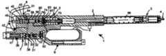
- FIG. 1Ashows a vertical view of a device according to the preferred 30 embodiment of the invention.
- FIG. 1Bshows a schematic cross-section of the device according to the preferred embodiment of the invention, in operating condition.
- FIG. 1Cshows a schematic cross-section of FIG. 1A after initiation of an operating cycle.
- FIG. 1Dshows a detail of FIG. 1C at the time of shockwave generation.
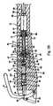
- FIGS. 2A to 2Deach show a detail of FIG. 1B , the whole of these figures corresponding to the entirety of FIG. 1B .
- the inventionconsists of a single-blow mechanical shockwave generation device ( FIG. 1A and FIG. 1B ) including striking device 2 which strikes, at high speed, generation device which generate a shockwave 3 .
- the shockwaveis transferred through shockwave transfer device 4 to an object to be disintegrated, with which said transfer device is put into direct or indirect contact.
- Striking device 2is put into motion by the expansion of a high pressure gas introduced, prior to each shockwave generation, into accumulation device 5 supplied with high pressure gas, from independent very high pressure gas stores 6 , by way of gas expansion device 7 and of supply and sealing devices.
- the gas stored in accumulation device 5is released by manual operating of control device 8 which renders gastight, through a sealing device, the intercommunication between stores 6 and expansion device 7 , on the one hand, and with accumulation device 5 , on the other.
- Manual operating of the control device 8establishes intercommunication between accumulation device 5 and striking device 2 .
- Return to the initial condition of striking device 2is ensured by the release of the accumulated energy, by mechanical device, during the shockwave production cycle.
- Return to initial condition of control device 8is ensured by the action of high pressure gases which remained at expansion device 7 and by the corresponding supply device.
- the gas usedcan be assimilated to a perfect gas at operating temperature, which is approximately twenty degree Celsius, in an accumulation chamber, making up an accumulation device, and at operating pressure which is a high pressure of approximately fifteen to thirty bar, and chemically compatible with its intended utilization.
- the gascan be air or nitrogen from a gas cylinder pressurized at a very high pressure of approximately two hundred bar, making up an independent gas store whose content can vary from half a liter to a few liters. It is connected to the single-blow mechanical shockwave generation device 1 via a flexible hose and through a pressure-relief valve. The hose and valve make up a pressure-relief device that is secured to the gas cylinder and which reduces the very high pressure from two hundred bar to a high pressure of fifteen to thirty bar.
- the gas usedis, for example, carbonic gas commercially available in a single-use gas micro-container 9 ( FIG. 2A ), making up a gas store of a content of approximately two centiliters at a pressure of approximately seventy bar, in which the carbonic gas is liquid, permitting storage of a significant carbonic gas volume in a small store.
- Carbonic gasis also known as carbon dioxide gas. The description hereinafter can also apply to other gases whereas remaining within the scope of the invention.
- the gas micro-container 9is comprised of a cylindrical body 10 whose outer diameter is approximately eighteen millimeters, and whose rear end 11 is closed by a hemispherical wall and front end 12 is extended by a stepped section, then by a neck 13 comprising a lateral part, essentially cylindrical, closed by a closing capsule 14 .
- the stepped section and neck 13 assemblyfeatures a length of approximately thirteen millimeters and the total length of the assembly is approximately eighty millimeters.
- Gas micro-container 9is directly integrated into single-blow mechanical shockwave generation device 1 . It is housed into cradle 15 comprised of two half-cradles.
- Front half-cradle 16is comprised of a revolution-cylindrical bore, along first symmetry axis 17 , of a diameter slightly larger than that of gas micro-container body 9 , and features a bottom section fitted with calibrated receptacle 18 which accommodates neck 13 of gas micro-container 9 .
- the lateral partis equipped with a first sealing device of first type 19 , with respect to the lateral part of neck 13 , whereas the central part of calibrated receptacle 18 features a perforation device 20 which pierces closing capsule 14 .
- Rear half-cradle 21is comprised of holding device 22 for the hemispherical bottom section of gas micro-container 9 , centered on the first symmetry axis 17 , and capable of sliding, parallel to the latter, thanks to guide stir-up 24 and clamping device 23 which bears upon front half-cradle 16 .
- the guide stir-upfeatures wide lateral openings which allow sliding of front end 12 of gas micro-container 9 into calibrated receptacle 18 of front half-cradle 16 , when the rear half-cradle 21 is retracted.
- Perforation device 20features a gas transfer device.
- Perforation device 20is, for example, of the type used on single-use butane gas cylinders, and a gas transfer device is a central cylindrical bore 25 allowing circulation of the gas from micro-container 9 .
- Perforation device 20is intercommunicated, through a first duct 26 , with pressure-relief device 27 , integrated with single-blow mechanical shock with generation device 1 , making up a gas pressure-relief device 7 ( FIG. 1A and FIG. 1B ).
- first cylinder revolution chamber 28( FIG. 2A ) in the rear section, from which first duct 26 is routed, and whose front section includes a first circular aperture edged by a second sealing device of the first type 29 .
- the first circular apertureextends into a second duct 30 in which, to permit gas passage, valve shank 31 of a gas supply valve slides freely, said valve featuring a valve head 32 located in first chamber 28 , and of a diameter significantly smaller than that of first chamber 28 , whose lower section features an annular sealing surface which surrounds valve shank 31 .
- the upper part of valve head 32is pushed back by a first calibrated spring 33 in order to press the annular sealing surface of valve head 32 onto the second sealing device of the first type 29 .
- valve shank 31slides through a first bore 34 , of a defined depth, acting as a guide, and machined in the head of a first cylindrical piston 35 , whose bottom, of first bore 34 , acts as a pusher, pushing back valve shank 31 .
- the first piston 35slides through second revolution-cylindrical chamber 36 which it divides into a first and a second space, of variable volume, sealed from each other by way of a first sealing device of the second type, solid with first piston 35 .
- Second duct 30leads into the rear section 38 of second chamber 36 , partly separating the first space of second chamber 36 , through a second circular aperture allowing free sliding of valve shank 31 and intercommunicating second chamber 36 with the gas circuit.
- Rear section 38 of second chamber 36acts as a mechanical stop for the head of first piston 35 .
- the second space, partly separated by front section 39 of second chamber 36includes a piston stop 40 , coaxial with that of second chamber 35 , thereby limiting the stroke of first piston 35 and acting as a guide for a second calibrated spring 41 .
- the assemblycomprised by first and second chambers 28 and 36 , the gas supply valve, first piston 35 , first and second calibrated springs 33 and 41 , makes up a gas pressure-relief device 7 ( FIG. 1A and FIG. 1B ) allowing a nominal pressure, defined with a good accuracy comprised between fifteen and thirty bar, to be established in the second gas duct 30 ( FIG. 2A ) which surrounds valve shank 31 .
- a third duct 42( FIG. 2B ), coming out from second duct 30 , leads through the lateral wall to a third revolution-cylindrical chamber 43 .
- the third chamberincludes a rear section 44 in which a second piston 45 slides.
- This pistoncomprises a second gas sealing device of the second type 46 , a rear section 47 and a front section 48 .
- the bottom of rear section 44 in third chamber 43features a circular aperture through which a first cylindrical pusher 49 passes freely, said pusher 49 being solid with rear section 47 of the second piston 45 and preferably oriented coaxially with the second revolution symmetry axis 50 of third chamber 43 , which is actuated by manual operating device of control device 8 ( FIG. 1A and FIG. 1B ).
- the manual operating device for first pusher 49preferably consist of pushing-in second piston 45 into third chamber 43 .
- a manual deviceis, for example, comprised of a lever 51 hinged around a rotation axis 52 , perpendicular and offset with respect to the revolution symmetry axis 50 of third chamber 43 , and comprising a symmetry plane which contains revolution symmetry axis 50 , and perpendicular to rotation axis 52 .
- the motions of hinged lever 51are limited by a stop 53 .
- the front section 48 of second piston 45features a revolution-cylindrical control rod 54 , with a captive end on front side 48 of first piston 45 and a free end 55 freely passing through a fourth revolution cylindrical duct 56 , and coaxial with the revolution symmetry axis 50 of third chamber 43 .
- the fourth duct 56 leading from the bottom of the front section 57 of third chamber 43is edged by a coaxial tapered revolution surface which acts as a guide for a third sealing device of the second type 58 .
- the sealing device 58which is neutralized, allows gas flow into the fourth duct 56 when second piston 45 is bearing against the bottom of the rear section 44 of third chamber 43 .
- sealing device 58penetrates into fourth duct 56 and ensures gas sealing of the front section 57 of third chamber 43 .
- Control rod 54extends and its free end 55 penetrates into a second bore 59 , solid with the body of third chamber 43 .
- the free end 55 of control rod 54internal to second bore 59 , includes a fourth sealing device of the second type 60 .
- the stroke of second piston 45is limited at rear position by the mechanical stop of its rear section 47 on the bottom of the rear section 44 of third chamber 43 , and is limited in front position by the mechanical stop of free end 55 of control rod 54 on the bottom 61 of second bore 59 . In the front position of second piston 45 , the third sealing device of the second type 58 blanks off the fourth duct 56 .
- a fifth duct 62( FIG. 2B ) includes an inlet aperture leading into the fourth duct 56 , downstream of the position of the fourth sealing device of the second type 58 , as well as an outlet aperture leading into the rear section of a fourth chamber 64 , which is a high pressure gas accumulation device, preferably revolution-cylindrical on a symmetry axis which is merged with that of second stage 59 .
- This fourth chamberincludes a discharge valve 65 .
- the valveis comprised of a valve body 66 , which is tubular, revolution-cylindrical, and coaxial with that of fourth chamber 64 , and of a diameter of approximately one third of that of fourth chamber 64 .
- the valveincludes a valve head 67 , featuring a flat rear section and a tapered revolution front section 122 , of a diameter practically double of that of the valve body on which it connects.
- the valveincludes a valve body base 68 which slides through a third bore 69 , of a diameter the same order of magnitude as that valve body 66 , featuring a third sealing device of the first type 70 which cooperates with valve body base 68 .
- the third bore 69is machined in the bottom above front section 71 of the fourth chamber 64 , and leads into a fifth chamber 72 which is an expansion chamber.
- valve head 67is kept pressed against the bottom of rear section 63 of fourth chamber 64 by a first helical spring 73 which bears on the bottom of front section 71 of fourth chamber 64 .
- the rear face of valve head 67which is circular, features an annular sealing zone next to its edge, which cooperates with a first sealing device of the third type 74 , solid with the bottom of rear section 63 of fourth chamber 64 .
- the tubular internal space of valve 66makes up a sixth duct 75 whose inlet aperture, at the rear face of valve head 67 , is flared and essentially tapered.
- valve head 67features a second cylindrical pusher 76 , coaxial with second bore 59 , comprising a free end 77 and a captive end connected to the rear side of valve head 67 by spacers 78 , integrated in the flared aperture of sixth duct 75 , and sliding in a fourth revolution bore 79 which interconnects the bottom of rear section 63 of fourth chamber 64 with the bottom of second bore 59 .
- a fourth sealing device of the first type 80solid with fourth bore 79 , ensures sealing between second bore 59 and sixth duct 75 .
- Second pusher 76features a diameter significantly smaller than that of second bore 59 , and a total length which is such that, when valve head 67 cooperates with the first sealing device of the third type 74 to isolate the sixth duct 75 from fourth chamber 64 , the free end 77 of second pusher 76 leads into the bottom of second bore 59 .
- the fourth chamber 64is intercommunicated through sixth duct 75 with fifth chamber 72 .
- the fifth chamber 72is of revolution-cylindrical shape, with a rear section 81 , in which sixth duct 75 opens, and a front section 82 from which a fifth revolution-cylindrical bore 83 begins.
- the fifth bore 83is preferably coaxial with the symmetry axis of fifth chamber 72 .
- Fifth chamber 72features a diameter slightly larger than that of valve body base 68 , and a significantly smaller length.
- Fifth bore 83( FIG. 2C ) leads into a sixth cylindrical rotation chamber 84 , which is coaxial with fifth bore 83 , of a diameter essentially equal to that of valve body base 68 and a length essentially double of that of fourth chamber 64 .
- Fifth bore 83features a decompression zone 85 of a slightly larger diameter, leading into sixth chamber 84 , and of a length essentially equal to one third of the length of fifth bore 83 .
- Sixth chamber 84features a rear section 86 in which fifth bore 83 leads, and from which at least one seventh duct 87 begins.
- the duct 87is open to the atmosphere either directly, or via a check valve 88 .
- Sixth chamber 84comprises a front section 89 in whose bottom a seventh revolution-cylindrical chamber leads, coaxial with sixth chamber 90 ( FIG. 2C and FIG. 2D ), intercommunicated with sixth chamber 84 via a sixth revolution-cylindrical bore 91 , of a diameter significantly larger than that of fifth bore 83 , and smaller than that of sixth chamber 90 .
- Fifth bore 83( FIG. 2C ) acts as guide and drive device for a striking hammer 92 , making up a striking device.
- Striking hammer 92is comprised of hammer body 93 , of low thickness, and of a diameter slightly smaller than that of the sixth chamber in which it is located, featuring a rear face directed towards the rear section 86 of sixth chamber 84 , and a front face, directed towards the front section 89 of sixth chamber 84 .
- a third, revolution-cylindrical piston 94coaxial with fifth bore 83 is solid with the rear face of hammer body 93 , and slides through fifth bore 83 .
- Third piston 94features a diameter slightly smaller than that of fifth bore 83 , in order to obtain sufficient sealing to permit its propulsion by gases.
- a revolution-cylindrical striking head 95coaxial with third piston 94 , is secured to the front face of hammer body 93 .
- Striking head 95is of a diameter significantly larger than that of third piston 94 , and a length of approximately one quarter of the length of third piston 94 .
- a second helical spring 96which bears on front section 89 of sixth chamber 84 , and on hammer body 93 , presses the hammer body onto the bottom of rear section 86 of sixth chamber 84 , therefore keeping third piston 94 depressed in fifth bore 83 .
- Seventh chamber 90( FIG. 2D ) includes a rear section 97 intercommunicating with sixth chamber 84 through sixth bore 91 , and a front section 98 whose bottom features a seventh revolution-cylindrical bore 99 coaxial with seventh chamber 90 , and of a diameter essentially equal to fifth bore 83 , thereby allowing seventh chamber 90 to intercommunicate with the rear section 100 of eighth chamber 101 .
- Seventh chamber 90contains a shockwave generating interface device 102 comprised of a revolution-cylindrical interface device body 103 , capable of sliding in seventh chamber 90 , and comprising a fifth sealing device of the second type 104 , which isolates front section 98 of the seventh chamber from rear section 97 .
- the interface device body 103features a rear face directed towards rear section 97 of seventh chamber 90 , and a front face directed towards front section 98 of seventh chamber 90 .
- the rear face of interface device body 103comprises a strike anvil 105 , of the same diameter as striking head 95 , whose length, when cumulated with that of interface device body 103 , is essentially equal to the length of striking head 95 cumulated with that of hammer body 93 .
- the length of sixth bore 91is determined so that the free end 106 of strike anvil 105 protrudes from the bottom of front section 89 of sixth chamber 84 , and that distance 108 ( FIG.
- the front face of interface device body 103features a first shockwave transfer device 109 , revolution-cylindrical and coaxial with seventh chamber 90 , and of a diameter essentially equal to that of third piston 94 and a length essentially equal to that of strike anvil 105 .
- the length of seventh bore 99must be sufficient to ensure correct guidance of shockwave generation interface device 102 ; however, it must allow protrusion of first shockwave transfer device 109 in the bottom of rear section 106 of eighth chamber 101 .
- the front section 112 of eighth chamber 101comprises an eighth bore 113 , revolution cylindrical, coaxial with eighth chamber 101 , and of a small diameter, of approximately one half of the diameter of third piston 94 which intercommunicates with the outside.
- Eighth chamber 101contains a shockwave guide head 115 of a second shockwave guide device 114 , revolution-cylindrical, of a diameter slightly smaller than that of eighth chamber 101 , whose rear face 116 is flat-shaped and whose front face 117 is essentially flat-shaped and comprises, squarely secured at its centre, a shockwave guide rod 118 which passes through eighth bore 113 and which acts as guide for shockwave guide head 115 of the second shockwave guide device 114 .
- the single-blow mechanical shockwave generation device 1FIG. 1 A and FIG.
- first shockwave transfer device 109 and the length of eighth chamber 101are determined, amongst others, to match these requirements.
- first shockwave transfer device 109bears on second shockwave transfer device 114 located in eighth chamber 101 , interface device 102 is slightly pushed towards rear section 97 of seventh chamber 90 and third helical spring 110 is slightly compressed.
- the length and diameter of shockwave guide rod 118are generally dictated by the implementation conditions.
- the maximum efficiency of the shockwaveis obtained when the weight of striking hammer 92 ( FIG. 2C ) is equal to the weight of second shockwave transfer device 114 .
- Impedance adjustmentcan be performed, on the one hand, by acting on the diameter of shockwave guide head 115 ( FIG. 2D ) and, on the other, by acting, to the maximum possible extent, on the length of third piston 94 , while taking into account the operating requirements.
- Shockwave generationbegins by operating of hinged lever 51 ( FIG. 1C and FIG. 2B ) which pushes in first pusher 49 , which, in turn, pushes back second piston 45 into third chamber 43 , and control rod 54 moves in translation in third chamber 43 until the third sealing device of the second type 58 penetrates into fourth duct 56 and blanks off this duct so that fourth chamber 64 is isolated from the high pressure gas supply. Then, as first pusher 49 continues to be pressed in, the free end 55 of control rod 54 penetrates into second bore 59 until it pushes in the free end 77 of second pusher 76 , which, in turn, causes separation of valve head 67 from the first sealing device of the third type 74 and compression of the first helical spring 73 .
- Second helical spring 96then pushes back striking hammer 92 and third piston 94 into fifth bore 83 .
- First helical spring 73pushes back discharge valve 65 into the bottom of rear section 63 ( FIG. 1B and FIG. 2B ) of fourth chamber 64 and restores initial sealing by way of the first sealing device of the third type 74 when second pusher 76 can assume its initial position again by release of the action on hinged lever 51 , which permits the displacement of second piston 45 towards the rear sections 44 of third chamber 43 , under the effect of high gas pressure in third chamber 43 .
- the displacement motion of second piston 45causes the motion of control rod 54 until the third sealing device of the second type 58 escapes from fourth duct 56 , which allows gas supply to fourth chamber 64 .
- the pressure drop in third chamber 43initiates the pressure drop in third and second duct 43 and 30 , which initiates the previously described gas supply cycle.
- third chamber 43( FIG. 2B ) is interconnected to the outside by a second calibrated discharge valve 121 , in order to avoid a possible overpressure associated with gas reheating after expansion, or a leakage at valve head 32 ( FIG. 1A ) and at the first sealing device of the first type 19 .
- the single-blow mechanical shockwave generation device 1can be used for disintegration of urinary stones and can have a fourth chamber 64 whose volume is preferably comprised between one and three cubic centimeters, as well as a striking hammer of a weight of approximately ten grams.
- a successive shockwave triggering deviceis inserted between hinged lever 51 and first pusher 49 .
- This triggering deviceis activated by operation of lever 51 . This initiates the generation of several successive shockwaves, for example, in a number and at a pace predetermined by successive operations of first pusher 49 , without requiring the releasing of hinged lever 51 .
Landscapes
- Health & Medical Sciences (AREA)
- Surgery (AREA)
- Life Sciences & Earth Sciences (AREA)
- Engineering & Computer Science (AREA)
- Molecular Biology (AREA)
- Public Health (AREA)
- Vascular Medicine (AREA)
- Biomedical Technology (AREA)
- Heart & Thoracic Surgery (AREA)
- Medical Informatics (AREA)
- Orthopedic Medicine & Surgery (AREA)
- Animal Behavior & Ethology (AREA)
- General Health & Medical Sciences (AREA)
- Nuclear Medicine, Radiotherapy & Molecular Imaging (AREA)
- Veterinary Medicine (AREA)
- Mechanical Engineering (AREA)
- Surgical Instruments (AREA)
- Filling Or Discharging Of Gas Storage Vessels (AREA)
- Disintegrating Or Milling (AREA)
- Electrophonic Musical Instruments (AREA)
- Constitution Of High-Frequency Heating (AREA)
- Percussive Tools And Related Accessories (AREA)
- Percussion Or Vibration Massage (AREA)
Abstract
Description
Claims (18)
Priority Applications (1)
| Application Number | Priority Date | Filing Date | Title |
|---|---|---|---|
| US12/339,182US20090118741A1 (en) | 2003-02-14 | 2008-12-19 | Single-blow shockwave generation device |
Applications Claiming Priority (3)
| Application Number | Priority Date | Filing Date | Title |
|---|---|---|---|
| FR03/01793 | 2003-02-14 | ||
| FR0301793AFR2851153B1 (en) | 2003-02-14 | 2003-02-14 | GENERATING DEVICE OF A SHOCK WAVE WAVE. |
| PCT/FR2004/000208WO2004078048A1 (en) | 2003-02-14 | 2004-01-30 | Single-blow shockwave generation device |
Related Child Applications (1)
| Application Number | Title | Priority Date | Filing Date |
|---|---|---|---|
| US12/339,182ContinuationUS20090118741A1 (en) | 2003-02-14 | 2008-12-19 | Single-blow shockwave generation device |
Publications (2)
| Publication Number | Publication Date |
|---|---|
| US20060069395A1 US20060069395A1 (en) | 2006-03-30 |
| US7470274B2true US7470274B2 (en) | 2008-12-30 |
Family
ID=32749570
Family Applications (2)
| Application Number | Title | Priority Date | Filing Date |
|---|---|---|---|
| US10/545,107Expired - LifetimeUS7470274B2 (en) | 2003-02-14 | 2004-01-30 | Single-blow shockwave generation device |
| US12/339,182AbandonedUS20090118741A1 (en) | 2003-02-14 | 2008-12-19 | Single-blow shockwave generation device |
Family Applications After (1)
| Application Number | Title | Priority Date | Filing Date |
|---|---|---|---|
| US12/339,182AbandonedUS20090118741A1 (en) | 2003-02-14 | 2008-12-19 | Single-blow shockwave generation device |
Country Status (20)
| Country | Link |
|---|---|
| US (2) | US7470274B2 (en) |
| EP (1) | EP1605839B1 (en) |
| JP (1) | JP4509102B2 (en) |
| KR (1) | KR101041105B1 (en) |
| CN (1) | CN100400004C (en) |
| AT (1) | ATE417555T1 (en) |
| AU (1) | AU2004217584B2 (en) |
| BR (1) | BRPI0407337B8 (en) |
| CA (1) | CA2515525C (en) |
| DE (1) | DE602004018469D1 (en) |
| ES (1) | ES2319899T3 (en) |
| FR (1) | FR2851153B1 (en) |
| IL (1) | IL170046A (en) |
| MA (1) | MA27612A1 (en) |
| MX (1) | MXPA05008238A (en) |
| NO (1) | NO20054237L (en) |
| PL (1) | PL378444A1 (en) |
| RU (1) | RU2352274C2 (en) |
| UA (1) | UA86584C2 (en) |
| WO (1) | WO2004078048A1 (en) |
Cited By (16)
| Publication number | Priority date | Publication date | Assignee | Title |
|---|---|---|---|---|
| US20090118741A1 (en)* | 2003-02-14 | 2009-05-07 | Lma Urology Limited | Single-blow shockwave generation device |
| US20090187146A1 (en)* | 2007-12-19 | 2009-07-23 | Vance Products Inc. D/B/A Cook Urological Incorporated | Vacuum aspiration handle |
| US20100137760A1 (en)* | 2007-05-31 | 2010-06-03 | Manfred Schulz | Medical Apparatus For Treatment Of The Human Or Animal Body By Pressure Waves Or Shock Waves |
| US8337416B2 (en) | 2010-07-23 | 2012-12-25 | Cook Medical Technologies Llc | Biopsy device |
| US20130186173A1 (en)* | 2012-01-24 | 2013-07-25 | The United States Of America, As Represented By The Secretary, Department Of Health And Human Serv | Device for simulating explosive blast and imaging biological specimen |
| US8926625B2 (en) | 2009-03-27 | 2015-01-06 | Alain Lebet | Surgical device |
| US8936604B2 (en) | 2011-03-07 | 2015-01-20 | Frederic Mani | Pneumatic surgical instrument and corresponding methods for implanting, extracting and reorienting orthopedic implants |
| US8968326B2 (en) | 2012-02-07 | 2015-03-03 | Frederic Mani | Pneumatic surgical instrument and corresponding methods for implanting orthopedic implants in bone |
| US9498236B2 (en) | 2012-01-31 | 2016-11-22 | Hi Impacts Ltd | High pressure ballistic extracorporeal shockwave device, system and method of use |
| US9554965B2 (en) | 2008-10-14 | 2017-01-31 | Ferton Holding Sa | Device for introducing shock waves into a living body and use thereof |
| US9597152B2 (en) | 2011-09-10 | 2017-03-21 | Cook Medical Technologies Llc | Control handles for medical devices |
| US10252035B2 (en) | 2015-12-07 | 2019-04-09 | Cook Medical Techonologies Llc | Rotatable control handles for medical devices and methods of using rotatable control handles |
| US10349958B2 (en) | 2012-03-27 | 2019-07-16 | Cook Medical Technologies Llc | Lithotripsy probes and methods for performing lithotripsy |
| US11484724B2 (en) | 2015-09-30 | 2022-11-01 | Btl Medical Solutions A.S. | Methods and devices for tissue treatment using mechanical stimulation and electromagnetic field |
| US11806512B2 (en) | 2018-05-03 | 2023-11-07 | P-Tech Co., Ltd. | Needleless pain-free injection device |
| US12220380B2 (en) | 2015-09-30 | 2025-02-11 | Btl Medical Solutions A.S. | Methods and devices for tissue treatment using mechanical stimulation and electromagnetic field |
Families Citing this family (47)
| Publication number | Priority date | Publication date | Assignee | Title |
|---|---|---|---|---|
| DE102006024760A1 (en) | 2006-05-27 | 2007-12-06 | Aesculap Ag & Co. Kg | Surgical instrument |
| KR100771216B1 (en)* | 2006-06-16 | 2007-10-29 | 조도연 | Cylinder for Extracorporeal Shock Wave Therapy |
| US7431189B2 (en)* | 2006-08-02 | 2008-10-07 | Ethicon Endo-Surgery, Inc. | Pneumatically powered surgical cutting and fastening instrument with mechanical linkage coupling end effector and trigger motion |
| KR100738490B1 (en)* | 2006-08-30 | 2007-07-11 | 조도연 | Extracorporeal Shock Wave Therapy |
| US9458935B2 (en)* | 2006-10-06 | 2016-10-04 | Helmut Fricke | Lockable joint |
| BRPI0716183A2 (en)* | 2006-10-06 | 2013-09-17 | Helmut Fricke | lockable joint |
| KR100864310B1 (en)* | 2008-04-21 | 2008-10-20 | (주)아이티시 | Secondary Shock Wave Cylinder Using Tension Spring |
| ES2394197T3 (en)* | 2008-10-31 | 2013-01-23 | Ferton Holding Sa | Instrument for generating pressure waves as a shock wave for the treatment of biological tissue |
| DE102009033525A1 (en)* | 2009-07-17 | 2011-01-20 | Aesculap Ag | Compressed gas operated instrument, in particular a surgical instrument |
| US8910505B2 (en)* | 2012-03-21 | 2014-12-16 | The Johns Hopkins University | System and method for simulating primary and secondary blast |
| DE102012107292A1 (en) | 2012-08-08 | 2014-02-13 | Aesculap Ag | Pneumatically operated surgical instrument |
| CN102871830A (en)* | 2012-10-29 | 2013-01-16 | 黄佑庆 | Handheld shock-wave therapeutic machine |
| US9005213B2 (en) | 2012-11-16 | 2015-04-14 | DePuy Synthes Products, Inc. | Controlled force surgical implant impaction instrument |
| CN105407855A (en)* | 2013-06-04 | 2016-03-16 | 西格玛仪器控股有限责任公司 | Diagnostic and therapeutic treatment device, and related systems and methods of utilizing such a device |
| EP3127497B1 (en) | 2013-11-07 | 2018-01-31 | Cook Medical Technologies LLC | Balloon catheter with lithotripsy amplification system |
| CN104296594A (en)* | 2014-09-30 | 2015-01-21 | 天津福云天翼科技有限公司 | Hydraulic impact programming device |
| CN104473674B (en)* | 2014-12-11 | 2017-03-08 | 武汉浩宏科技有限公司 | Stone crusher in a kind of many power body |
| US11083512B2 (en) | 2016-08-31 | 2021-08-10 | DePuy Synthes Products, Inc. | Orthopedic device delivering a controlled, repeatable impact |
| CN108602180B (en)* | 2016-08-31 | 2022-12-20 | 德普伊新特斯产品公司 | Orthopedic device delivering controlled, repeatable impacts |
| WO2018044347A1 (en) | 2016-08-31 | 2018-03-08 | Corex, Llc | Orthopedic impacting device having a launched mass delivering a controlled, repeatable & reversible impacting force |
| KR101859735B1 (en)* | 2018-02-07 | 2018-05-21 | 주식회사 피테크 | Painless injection device |
| US11103262B2 (en) | 2018-03-14 | 2021-08-31 | Boston Scientific Scimed, Inc. | Balloon-based intravascular ultrasound system for treatment of vascular lesions |
| KR102104080B1 (en)* | 2018-05-02 | 2020-04-23 | 주식회사 피테크 | Sonic vibration device for painless syringe and painless sylinge having the same |
| KR102107578B1 (en)* | 2018-05-02 | 2020-05-07 | 주식회사 피테크 | Constant velocity infusion device for painless syringe and painless sylinge having the same |
| US11819229B2 (en) | 2019-06-19 | 2023-11-21 | Boston Scientific Scimed, Inc. | Balloon surface photoacoustic pressure wave generation to disrupt vascular lesions |
| KR102199724B1 (en)* | 2018-10-05 | 2021-01-07 | 주식회사 피테크 | Painless injection device without needle |
| WO2020086361A1 (en) | 2018-10-24 | 2020-04-30 | Boston Scientific Scimed, Inc. | Photoacoustic pressure wave generation for intravascular calcification disruption |
| CN109485004B (en)* | 2018-12-21 | 2024-06-18 | 上海梵洛科技有限公司 | Beverage extracting device |
| US11717139B2 (en) | 2019-06-19 | 2023-08-08 | Bolt Medical, Inc. | Plasma creation via nonaqueous optical breakdown of laser pulse energy for breakup of vascular calcium |
| US12402946B2 (en) | 2019-06-19 | 2025-09-02 | Boston Scientific Scimed, Inc. | Breakdown of laser pulse energy for breakup of vascular calcium |
| US11660427B2 (en) | 2019-06-24 | 2023-05-30 | Boston Scientific Scimed, Inc. | Superheating system for inertial impulse generation to disrupt vascular lesions |
| US12280223B2 (en) | 2019-06-26 | 2025-04-22 | Boston Scientific Scimed, Inc. | Focusing element for plasma system to disrupt vascular lesions |
| US11583339B2 (en) | 2019-10-31 | 2023-02-21 | Bolt Medical, Inc. | Asymmetrical balloon for intravascular lithotripsy device and method |
| US12102384B2 (en) | 2019-11-13 | 2024-10-01 | Bolt Medical, Inc. | Dynamic intravascular lithotripsy device with movable energy guide |
| US12274497B2 (en) | 2019-12-18 | 2025-04-15 | Bolt Medical, Inc. | Multiplexer for laser-driven intravascular lithotripsy device |
| US11672599B2 (en) | 2020-03-09 | 2023-06-13 | Bolt Medical, Inc. | Acoustic performance monitoring system and method within intravascular lithotripsy device |
| US20210290286A1 (en) | 2020-03-18 | 2021-09-23 | Bolt Medical, Inc. | Optical analyzer assembly and method for intravascular lithotripsy device |
| US11707323B2 (en) | 2020-04-03 | 2023-07-25 | Bolt Medical, Inc. | Electrical analyzer assembly for intravascular lithotripsy device |
| US12295654B2 (en) | 2020-06-03 | 2025-05-13 | Boston Scientific Scimed, Inc. | System and method for maintaining balloon integrity within intravascular lithotripsy device with plasma generator |
| US12207870B2 (en) | 2020-06-15 | 2025-01-28 | Boston Scientific Scimed, Inc. | Spectroscopic tissue identification for balloon intravascular lithotripsy guidance |
| US12016610B2 (en) | 2020-12-11 | 2024-06-25 | Bolt Medical, Inc. | Catheter system for valvuloplasty procedure |
| EP4277548B1 (en) | 2021-01-12 | 2025-06-04 | Bolt Medical, Inc. | Balloon assembly for valvuloplasty catheter system |
| US11672585B2 (en) | 2021-01-12 | 2023-06-13 | Bolt Medical, Inc. | Balloon assembly for valvuloplasty catheter system |
| FR3120247B1 (en)* | 2021-03-01 | 2023-09-29 | Montabert Roger | Hydraulic rotary hammer drill equipped with a stop piston |
| US11648057B2 (en) | 2021-05-10 | 2023-05-16 | Bolt Medical, Inc. | Optical analyzer assembly with safety shutdown system for intravascular lithotripsy device |
| US11806075B2 (en) | 2021-06-07 | 2023-11-07 | Bolt Medical, Inc. | Active alignment system and method for laser optical coupling |
| US11839391B2 (en) | 2021-12-14 | 2023-12-12 | Bolt Medical, Inc. | Optical emitter housing assembly for intravascular lithotripsy device |
Citations (10)
| Publication number | Priority date | Publication date | Assignee | Title |
|---|---|---|---|---|
| US3250334A (en)* | 1963-08-13 | 1966-05-10 | Sussman Ernst | Impact tools |
| US4016873A (en) | 1976-04-01 | 1977-04-12 | Anderson Otis F | Pneumatic impacter |
| US4716890A (en) | 1986-01-29 | 1988-01-05 | Bichel Ronald A | Chiropractic thruster |
| EP0317507A1 (en) | 1987-11-18 | 1989-05-24 | Ferton Holding | Apparatus for acting by means of ultrasonic vibrations upon an object |
| WO1995022934A1 (en) | 1994-02-23 | 1995-08-31 | Synvasive Technology, Inc. | Surgical chisel tool and method |
| US5449363A (en)* | 1994-05-06 | 1995-09-12 | Browne Medical Systems, Inc. | Endoscopic lithotripsy system |
| US5613483A (en)* | 1995-11-09 | 1997-03-25 | Lukas; Michael A. | Gas powered gun |
| WO1998026705A2 (en) | 1996-12-18 | 1998-06-25 | Pck Elektronik Sanayi Ve Ticaret Limited Sirketi | Intracorporeal vibration lithotripter |
| US5906623A (en) | 1995-12-11 | 1999-05-25 | Boston Scientific Corporation | Lithotripsy system |
| EP1163882A1 (en) | 2000-06-15 | 2001-12-19 | Ferton Holding SA | Intracorporeal lithotripter for removal of calculi |
Family Cites Families (7)
| Publication number | Priority date | Publication date | Assignee | Title |
|---|---|---|---|---|
| US4298074A (en)* | 1976-08-09 | 1981-11-03 | American Safety Equipment Corporation | Surgical device using impulse motor |
| JPS60142842A (en)* | 1983-12-28 | 1985-07-29 | オリンパス光学工業株式会社 | Surgical incision instrument |
| JPS61154547A (en)* | 1984-12-13 | 1986-07-14 | 細谷火工株式会社 | Stone crusher |
| SU1680107A1 (en)* | 1988-08-04 | 1991-09-30 | Предприятие П/Я А-7094 | Device for electrohydraulic crushing of concrements in the human body by focused shock waves |
| CA2271958C (en)* | 1996-12-09 | 2000-02-08 | Benjamin V. Knelson | Centrifugal separator with injection of fluidizing liquid between non-fluidized recesses |
| RU2155543C2 (en)* | 1998-12-16 | 2000-09-10 | Захаров Виктор Николаевич | Shock-wave generator for crushing of concrements |
| FR2851153B1 (en)* | 2003-02-14 | 2005-04-08 | Alain Lebet | GENERATING DEVICE OF A SHOCK WAVE WAVE. |
- 2003
- 2003-02-14FRFR0301793Apatent/FR2851153B1/ennot_activeExpired - Lifetime
- 2004
- 2004-01-30UAUAA200508731Apatent/UA86584C2/enunknown
- 2004-01-30DEDE602004018469Tpatent/DE602004018469D1/denot_activeExpired - Lifetime
- 2004-01-30EPEP04706707Apatent/EP1605839B1/ennot_activeExpired - Lifetime
- 2004-01-30JPJP2006505663Apatent/JP4509102B2/ennot_activeExpired - Fee Related
- 2004-01-30ESES04706707Tpatent/ES2319899T3/ennot_activeExpired - Lifetime
- 2004-01-30AUAU2004217584Apatent/AU2004217584B2/ennot_activeExpired
- 2004-01-30CNCNB2004800041769Apatent/CN100400004C/ennot_activeExpired - Lifetime
- 2004-01-30BRBRPI0407337Apatent/BRPI0407337B8/ennot_activeIP Right Cessation
- 2004-01-30CACA2515525Apatent/CA2515525C/ennot_activeExpired - Lifetime
- 2004-01-30KRKR1020057014992Apatent/KR101041105B1/ennot_activeExpired - Fee Related
- 2004-01-30ATAT04706707Tpatent/ATE417555T1/ennot_activeIP Right Cessation
- 2004-01-30MXMXPA05008238Apatent/MXPA05008238A/enactiveIP Right Grant
- 2004-01-30PLPL378444Apatent/PL378444A1/ennot_activeApplication Discontinuation
- 2004-01-30USUS10/545,107patent/US7470274B2/ennot_activeExpired - Lifetime
- 2004-01-30WOPCT/FR2004/000208patent/WO2004078048A1/enactiveApplication Filing
- 2004-01-30RURU2005128552/14Apatent/RU2352274C2/ennot_activeIP Right Cessation
- 2005
- 2005-07-15MAMA28392Apatent/MA27612A1/enunknown
- 2005-08-02ILIL170046Apatent/IL170046A/ennot_activeIP Right Cessation
- 2005-09-13NONO20054237Apatent/NO20054237L/ennot_activeApplication Discontinuation
- 2008
- 2008-12-19USUS12/339,182patent/US20090118741A1/ennot_activeAbandoned
Patent Citations (12)
| Publication number | Priority date | Publication date | Assignee | Title |
|---|---|---|---|---|
| US3250334A (en)* | 1963-08-13 | 1966-05-10 | Sussman Ernst | Impact tools |
| US4016873A (en) | 1976-04-01 | 1977-04-12 | Anderson Otis F | Pneumatic impacter |
| US4716890A (en) | 1986-01-29 | 1988-01-05 | Bichel Ronald A | Chiropractic thruster |
| EP0317507A1 (en) | 1987-11-18 | 1989-05-24 | Ferton Holding | Apparatus for acting by means of ultrasonic vibrations upon an object |
| US5160336A (en) | 1987-11-18 | 1992-11-03 | Ferton Holding | Device for acting by ultrasonic vibrations on an object |
| WO1995022934A1 (en) | 1994-02-23 | 1995-08-31 | Synvasive Technology, Inc. | Surgical chisel tool and method |
| US5449363A (en)* | 1994-05-06 | 1995-09-12 | Browne Medical Systems, Inc. | Endoscopic lithotripsy system |
| US5613483A (en)* | 1995-11-09 | 1997-03-25 | Lukas; Michael A. | Gas powered gun |
| US5906623A (en) | 1995-12-11 | 1999-05-25 | Boston Scientific Corporation | Lithotripsy system |
| WO1998026705A2 (en) | 1996-12-18 | 1998-06-25 | Pck Elektronik Sanayi Ve Ticaret Limited Sirketi | Intracorporeal vibration lithotripter |
| EP1163882A1 (en) | 2000-06-15 | 2001-12-19 | Ferton Holding SA | Intracorporeal lithotripter for removal of calculi |
| US20020010486A1 (en) | 2000-06-15 | 2002-01-24 | Ferton Holding S.A. | Device for removal of calculi |
Cited By (21)
| Publication number | Priority date | Publication date | Assignee | Title |
|---|---|---|---|---|
| US20090118741A1 (en)* | 2003-02-14 | 2009-05-07 | Lma Urology Limited | Single-blow shockwave generation device |
| US20100137760A1 (en)* | 2007-05-31 | 2010-06-03 | Manfred Schulz | Medical Apparatus For Treatment Of The Human Or Animal Body By Pressure Waves Or Shock Waves |
| US20090187146A1 (en)* | 2007-12-19 | 2009-07-23 | Vance Products Inc. D/B/A Cook Urological Incorporated | Vacuum aspiration handle |
| US7811256B2 (en) | 2007-12-19 | 2010-10-12 | Vance Products Inc. | Vacuum aspiration handle |
| US9554965B2 (en) | 2008-10-14 | 2017-01-31 | Ferton Holding Sa | Device for introducing shock waves into a living body and use thereof |
| US8926625B2 (en) | 2009-03-27 | 2015-01-06 | Alain Lebet | Surgical device |
| US8337416B2 (en) | 2010-07-23 | 2012-12-25 | Cook Medical Technologies Llc | Biopsy device |
| US8936604B2 (en) | 2011-03-07 | 2015-01-20 | Frederic Mani | Pneumatic surgical instrument and corresponding methods for implanting, extracting and reorienting orthopedic implants |
| US8936603B2 (en) | 2011-03-07 | 2015-01-20 | Frederic Mani | Pneumatic surgical instrument and corresponding methods for penetrating, resecting and microfracturing bone |
| US9999518B2 (en) | 2011-03-07 | 2018-06-19 | Biomet Global Supply Chain Center | Pneumatic surgical instrument and corresponding methods for implanting, extracting and reorienting orthopedic implants |
| US10925623B2 (en) | 2011-09-10 | 2021-02-23 | Cook Medical Technologies Llc | Control handles for medical devices |
| US9597152B2 (en) | 2011-09-10 | 2017-03-21 | Cook Medical Technologies Llc | Control handles for medical devices |
| US9217698B2 (en)* | 2012-01-24 | 2015-12-22 | The United States Of America, As Represented By The Secretary, Department Of Health And Human Services | Device for simulating explosive blast and imaging biological specimen |
| US20130186173A1 (en)* | 2012-01-24 | 2013-07-25 | The United States Of America, As Represented By The Secretary, Department Of Health And Human Serv | Device for simulating explosive blast and imaging biological specimen |
| US9498236B2 (en) | 2012-01-31 | 2016-11-22 | Hi Impacts Ltd | High pressure ballistic extracorporeal shockwave device, system and method of use |
| US8968326B2 (en) | 2012-02-07 | 2015-03-03 | Frederic Mani | Pneumatic surgical instrument and corresponding methods for implanting orthopedic implants in bone |
| US10349958B2 (en) | 2012-03-27 | 2019-07-16 | Cook Medical Technologies Llc | Lithotripsy probes and methods for performing lithotripsy |
| US11484724B2 (en) | 2015-09-30 | 2022-11-01 | Btl Medical Solutions A.S. | Methods and devices for tissue treatment using mechanical stimulation and electromagnetic field |
| US12220380B2 (en) | 2015-09-30 | 2025-02-11 | Btl Medical Solutions A.S. | Methods and devices for tissue treatment using mechanical stimulation and electromagnetic field |
| US10252035B2 (en) | 2015-12-07 | 2019-04-09 | Cook Medical Techonologies Llc | Rotatable control handles for medical devices and methods of using rotatable control handles |
| US11806512B2 (en) | 2018-05-03 | 2023-11-07 | P-Tech Co., Ltd. | Needleless pain-free injection device |
Also Published As
| Publication number | Publication date |
|---|---|
| AU2004217584B2 (en) | 2009-09-17 |
| CN1750791A (en) | 2006-03-22 |
| BRPI0407337B1 (en) | 2016-11-29 |
| BRPI0407337A (en) | 2006-01-10 |
| BRPI0407337B8 (en) | 2021-06-22 |
| JP2006517851A (en) | 2006-08-03 |
| KR101041105B1 (en) | 2011-06-13 |
| EP1605839B1 (en) | 2008-12-17 |
| RU2005128552A (en) | 2006-01-27 |
| CA2515525C (en) | 2011-04-26 |
| KR20050098932A (en) | 2005-10-12 |
| UA86584C2 (en) | 2009-05-12 |
| FR2851153A1 (en) | 2004-08-20 |
| DE602004018469D1 (en) | 2009-01-29 |
| FR2851153B1 (en) | 2005-04-08 |
| US20060069395A1 (en) | 2006-03-30 |
| WO2004078048A1 (en) | 2004-09-16 |
| RU2352274C2 (en) | 2009-04-20 |
| NO20054237L (en) | 2005-09-13 |
| JP4509102B2 (en) | 2010-07-21 |
| ATE417555T1 (en) | 2009-01-15 |
| EP1605839A1 (en) | 2005-12-21 |
| IL170046A (en) | 2009-12-24 |
| MXPA05008238A (en) | 2006-03-28 |
| AU2004217584A1 (en) | 2004-09-16 |
| CA2515525A1 (en) | 2004-09-16 |
| ES2319899T3 (en) | 2009-05-14 |
| HK1087603A1 (en) | 2006-10-20 |
| MA27612A1 (en) | 2005-11-01 |
| PL378444A1 (en) | 2006-04-03 |
| US20090118741A1 (en) | 2009-05-07 |
| CN100400004C (en) | 2008-07-09 |
Similar Documents
| Publication | Publication Date | Title |
|---|---|---|
| US7470274B2 (en) | Single-blow shockwave generation device | |
| US20120277747A1 (en) | Trauma nail accumulator | |
| CN109070324A (en) | Orthopedic impact device with the transmitting mass for transmitting controllable, repeatable and reversible impact force | |
| CA2349441A1 (en) | Device for removal of calculi | |
| WO1981003303A1 (en) | Self-contained gas powered surgical stapler | |
| JPH10513391A (en) | Injection device for high pressure injection of liquid | |
| CN105534568A (en) | Apparatus for treating the human or animal body with mechanical strokes | |
| HK1087603B (en) | Single-blow shockwave generation device | |
| CN1329007C (en) | Air passage control system of tee joint vacuum valve in use for stone crusher of ballistic curve | |
| CN201642201U (en) | Medical mini-type lithotripter | |
| CN111588458B (en) | High-pressure inflatable bone nail | |
| CN206651857U (en) | A kind of ultrasonic femoral myelocavity file suitable for minimally invasive artificial full hip-joint replacement | |
| US20240335290A1 (en) | Pump having a volume amplification mechanism for an inflatable penile prosthesis | |
| US4926859A (en) | A medical treatment device for treating an undesired formation in a living body | |
| CN113842179B (en) | Balloon opening device for shoulder arthroscopic surgery | |
| US20250268616A1 (en) | Lithotripsy device for breaking up calculi with an axially movable acceleration tube, and method for accelerating a projectile of a lithotripsy device | |
| CN213130694U (en) | Inflatable expansion structure | |
| CN2468675Y (en) | Handle of pneumatic ballistic lithotriptor | |
| CN114159155A (en) | Minimally invasive urinary system calculus crushing device | |
| CN120267353A (en) | External shock wave treatment handle and therapeutic instrument | |
| CN116035782A (en) | Knee joint revision tibia support extractor | |
| CN2406621Y (en) | Safety exsufflation sleeve for abdominoscope | |
| CN108498148A (en) | The broken suction device and method of belly cavity tumor of the small-sized bag container of adapted | |
| RU2002101206A (en) | Guided projectile |
Legal Events
| Date | Code | Title | Description |
|---|---|---|---|
| AS | Assignment | Owner name:DULIVER INTERNATIONAL LTD., VIRGIN ISLANDS, BRITIS Free format text:ASSIGNMENT OF ASSIGNORS INTEREST;ASSIGNOR:LEBET, ALAIN;REEL/FRAME:017424/0239 Effective date:20051213 | |
| AS | Assignment | Owner name:LMA UROLOGY LIMITED, SEYCHELLES Free format text:ASSIGNMENT OF ASSIGNORS INTEREST;ASSIGNOR:DULIVER INTERNATIONAL LIMITED;REEL/FRAME:021839/0786 Effective date:20060209 | |
| STCF | Information on status: patent grant | Free format text:PATENTED CASE | |
| FEPP | Fee payment procedure | Free format text:PAT HOLDER NO LONGER CLAIMS SMALL ENTITY STATUS, ENTITY STATUS SET TO UNDISCOUNTED (ORIGINAL EVENT CODE: STOL); ENTITY STATUS OF PATENT OWNER: LARGE ENTITY | |
| REFU | Refund | Free format text:REFUND - SURCHARGE, PETITION TO ACCEPT PYMT AFTER EXP, UNINTENTIONAL (ORIGINAL EVENT CODE: R2551); ENTITY STATUS OF PATENT OWNER: LARGE ENTITY | |
| FPAY | Fee payment | Year of fee payment:4 | |
| AS | Assignment | Owner name:COOK INCORPORATED, INDIANA Free format text:ASSIGNMENT OF ASSIGNORS INTEREST;ASSIGNOR:LMA UROLOGY LTD.;REEL/FRAME:037069/0459 Effective date:20150602 | |
| AS | Assignment | Owner name:COOK MEDICAL TECHNOLOGIES LLC, INDIANA Free format text:ASSIGNMENT OF ASSIGNORS INTEREST;ASSIGNOR:COOK INCORPORATED;REEL/FRAME:037084/0680 Effective date:20150603 | |
| FPAY | Fee payment | Year of fee payment:8 | |
| MAFP | Maintenance fee payment | Free format text:PAYMENT OF MAINTENANCE FEE, 12TH YEAR, LARGE ENTITY (ORIGINAL EVENT CODE: M1553); ENTITY STATUS OF PATENT OWNER: LARGE ENTITY Year of fee payment:12 |