US7470247B2 - Ureteral stent - Google Patents
Ureteral stentDownload PDFInfo
- Publication number
- US7470247B2 US7470247B2US10/832,495US83249504AUS7470247B2US 7470247 B2US7470247 B2US 7470247B2US 83249504 AUS83249504 AUS 83249504AUS 7470247 B2US7470247 B2US 7470247B2
- Authority
- US
- United States
- Prior art keywords
- struts
- retention disk
- lumen
- stent
- proximal end
- Prior art date
- Legal status (The legal status is an assumption and is not a legal conclusion. Google has not performed a legal analysis and makes no representation as to the accuracy of the status listed.)
- Expired - Lifetime
Links
- 230000014759maintenance of locationEffects0.000claimsabstractdescription94
- 239000012528membraneSubstances0.000claimsabstractdescription31
- 239000012530fluidSubstances0.000claimsabstractdescription29
- 238000004891communicationMethods0.000claimsabstractdescription26
- 239000000463materialSubstances0.000claimsdescription33
- 210000000626ureterAnatomy0.000claimsdescription18
- 230000009975flexible effectEffects0.000claimsdescription17
- 210000003734kidneyAnatomy0.000claimsdescription15
- 238000005452bendingMethods0.000claimsdescription4
- 229910001000nickel titaniumInorganic materials0.000claimsdescription4
- 238000011084recoveryMethods0.000claimsdescription4
- 230000008859changeEffects0.000claimsdescription2
- 230000000284resting effectEffects0.000claims6
- 229920001296polysiloxanePolymers0.000description6
- 238000000034methodMethods0.000description5
- 210000003484anatomyAnatomy0.000description4
- 230000005012migrationEffects0.000description4
- 238000013508migrationMethods0.000description4
- 230000008021depositionEffects0.000description3
- 210000000232gallbladderAnatomy0.000description3
- 230000007794irritationEffects0.000description3
- 210000000244kidney pelvisAnatomy0.000description3
- 230000000704physical effectEffects0.000description3
- 230000002485urinary effectEffects0.000description3
- 210000002700urineAnatomy0.000description3
- 206010028980NeoplasmDiseases0.000description2
- 208000031481Pathologic ConstrictionDiseases0.000description2
- 208000031513cystDiseases0.000description2
- 238000001125extrusionMethods0.000description2
- 238000004519manufacturing processMethods0.000description2
- 230000004048modificationEffects0.000description2
- 238000012986modificationMethods0.000description2
- 239000002861polymer materialSubstances0.000description2
- 230000008569processEffects0.000description2
- 238000010992refluxMethods0.000description2
- 239000010935stainless steelSubstances0.000description2
- 210000001635urinary tractAnatomy0.000description2
- 235000001674Agaricus brunnescensNutrition0.000description1
- 206010002329AneurysmDiseases0.000description1
- 208000002513Flank painDiseases0.000description1
- 208000007101Muscle CrampDiseases0.000description1
- 208000005392SpasmDiseases0.000description1
- 208000004608Ureteral ObstructionDiseases0.000description1
- HZEWFHLRYVTOIW-UHFFFAOYSA-N[Ti].[Ni]Chemical compound[Ti].[Ni]HZEWFHLRYVTOIW-UHFFFAOYSA-N0.000description1
- 230000004308accommodationEffects0.000description1
- 230000006978adaptationEffects0.000description1
- 229910045601alloyInorganic materials0.000description1
- 239000000956alloySubstances0.000description1
- 230000004075alterationEffects0.000description1
- 238000002399angioplastyMethods0.000description1
- 230000000845anti-microbial effectEffects0.000description1
- 239000004599antimicrobialSubstances0.000description1
- 238000010420art techniqueMethods0.000description1
- QVGXLLKOCUKJST-UHFFFAOYSA-Natomic oxygenChemical compound[O]QVGXLLKOCUKJST-UHFFFAOYSA-N0.000description1
- 210000000013bile ductAnatomy0.000description1
- 238000000576coating methodMethods0.000description1
- 210000001953common bile ductAnatomy0.000description1
- 210000003459common hepatic ductAnatomy0.000description1
- 230000006835compressionEffects0.000description1
- 238000007906compressionMethods0.000description1
- 238000012790confirmationMethods0.000description1
- 210000001096cystic ductAnatomy0.000description1
- 230000003247decreasing effectEffects0.000description1
- 230000009977dual effectEffects0.000description1
- 210000001198duodenumAnatomy0.000description1
- 230000005489elastic deformationEffects0.000description1
- 239000013013elastic materialSubstances0.000description1
- 229920001971elastomerPolymers0.000description1
- 239000000806elastomerSubstances0.000description1
- 238000001839endoscopyMethods0.000description1
- 230000001747exhibiting effectEffects0.000description1
- 230000006870functionEffects0.000description1
- 230000002440hepatic effectEffects0.000description1
- 238000002513implantationMethods0.000description1
- 238000003780insertionMethods0.000description1
- 230000037431insertionEffects0.000description1
- 238000001990intravenous administrationMethods0.000description1
- 230000002262irrigationEffects0.000description1
- 238000003973irrigationMethods0.000description1
- 210000004185liverAnatomy0.000description1
- 238000005259measurementMethods0.000description1
- HLXZNVUGXRDIFK-UHFFFAOYSA-Nnickel titaniumChemical compound[Ti].[Ti].[Ti].[Ti].[Ti].[Ti].[Ti].[Ti].[Ti].[Ti].[Ti].[Ni].[Ni].[Ni].[Ni].[Ni].[Ni].[Ni].[Ni].[Ni].[Ni].[Ni].[Ni].[Ni].[Ni]HLXZNVUGXRDIFK-UHFFFAOYSA-N0.000description1
- 229910052760oxygenInorganic materials0.000description1
- 239000001301oxygenSubstances0.000description1
- 210000000496pancreasAnatomy0.000description1
- 210000000277pancreatic ductAnatomy0.000description1
- 230000010412perfusionEffects0.000description1
- 230000002572peristaltic effectEffects0.000description1
- 229920000642polymerPolymers0.000description1
- 230000000717retained effectEffects0.000description1
- 239000007779soft materialSubstances0.000description1
- 229910001220stainless steelInorganic materials0.000description1
- 229910001256stainless steel alloyInorganic materials0.000description1
- 230000036262stenosisEffects0.000description1
- 208000037804stenosisDiseases0.000description1
- 210000002784stomachAnatomy0.000description1
- 238000001356surgical procedureMethods0.000description1
- 239000012815thermoplastic materialSubstances0.000description1
- 238000002627tracheal intubationMethods0.000description1
Images


Classifications
- A—HUMAN NECESSITIES
- A61—MEDICAL OR VETERINARY SCIENCE; HYGIENE
- A61F—FILTERS IMPLANTABLE INTO BLOOD VESSELS; PROSTHESES; DEVICES PROVIDING PATENCY TO, OR PREVENTING COLLAPSING OF, TUBULAR STRUCTURES OF THE BODY, e.g. STENTS; ORTHOPAEDIC, NURSING OR CONTRACEPTIVE DEVICES; FOMENTATION; TREATMENT OR PROTECTION OF EYES OR EARS; BANDAGES, DRESSINGS OR ABSORBENT PADS; FIRST-AID KITS
- A61F2/00—Filters implantable into blood vessels; Prostheses, i.e. artificial substitutes or replacements for parts of the body; Appliances for connecting them with the body; Devices providing patency to, or preventing collapsing of, tubular structures of the body, e.g. stents
- A61F2/02—Prostheses implantable into the body
- A61F2/04—Hollow or tubular parts of organs, e.g. bladders, tracheae, bronchi or bile ducts
- A—HUMAN NECESSITIES
- A61—MEDICAL OR VETERINARY SCIENCE; HYGIENE
- A61M—DEVICES FOR INTRODUCING MEDIA INTO, OR ONTO, THE BODY; DEVICES FOR TRANSDUCING BODY MEDIA OR FOR TAKING MEDIA FROM THE BODY; DEVICES FOR PRODUCING OR ENDING SLEEP OR STUPOR
- A61M27/00—Drainage appliance for wounds or the like, i.e. wound drains, implanted drains
- A61M27/002—Implant devices for drainage of body fluids from one part of the body to another
- A61M27/008—Implant devices for drainage of body fluids from one part of the body to another pre-shaped, for use in the urethral or ureteral tract
Definitions
- the present inventionis related to ureteral stents, and more particularly, to methods and apparatus for preventing stent migration and reflux flow.
- Tubular prosthesesare used in a variety of medical procedures.
- stentsare often used in connection with assisting drainage from the kidney through the ureter, from the liver through the biliary ducts, from the dorsal or ventral pancreas through the pancreatic ducts, from the gall bladder through the cystic, hepatic, or common bile ducts, and the like.
- a leading reason for stent deployment in ductsis to provide drainage to circumvent a blockage. Blockage of ducts in the body can be a serious and very painful affliction that can result in death if not promptly and effectively treated. Blockages can occur for a number of reasons.
- stones or debris from such stonescan pass from the kidney into the ureter, where they become entrapped.
- stones or debriscan pass from the gall bladder into the bile ducts, where they become entrapped.
- cysts or tumors growing against the outer wall of the ductscan cause constriction of the ducts.
- internal or duct wall cysts or tumorscan act to block ducts.
- ureteral stentsThe main function of ureteral stents, for example, is to bypass ureteral obstruction and to provide urinary drainage from the kidney to the bladder for a period of time, typically a few days to several months.
- the ureteral stentis usually provided with drainage means such as a lumen for directing fluid from the renal pelvis to the bladder.
- Conventional stentsinclude openings provided along the stent for communication with the lumen to aide in drainage.
- ureteral stentsare also made with varying diameters, e.g., from 3 French (1 mm) to 16 French (5.28 mm), and typically, 4.5 French (1.5 mm) to 8.5 French (2.8 mm), and varying degrees of hardness.
- Ureteral stents with smaller diametersare usually easier to insert but may provide insufficient drainage, whereas stents with larger diameters allow for increasing drainage capacity through the ureter but may be difficult to insert.
- Current urinary stentscomprise a shaft commonly made of either single or dual durometer polymer material.
- Current shaft designsoften have unique profile cross-sections and hydrophilic or anti-microbial coatings, for example. This shaft typically resides in the ureter to provide drainage of urine after ureteroscopy procedures.
- Stiff ureteral stentsare easier to insert than are softer stents, but once inserted can lead to increased patient discomfort.
- Stiff stentsare less likely to accommodate the dynamic urinary tract anatomy that stretches and relaxes. The relative push and pull of the kidney and bladder is not accommodated for, therefore increasing patient discomfort from contact irritation of the stent within the anatomy.
- the lack of accommodation of the normal body movementsincreases the potential for the stent to migrate or dislodge from its intended location.
- stentsare either made of silicone or of a harder polymer. Silicone may increase patient comfort, but because of the softness of silicone, it is more difficult to guide the stent into the ureter. Once in the ureter, the softness of the silicone increases the likelihood of migration of the stent because rigid retention means are not available.
- stentshave been designed to address one or more of the above problems specifically, there are currently no devices incorporating features that can be used to bypass most of the aforementioned disadvantages. It would thus be desirable to have a stent that provides one or more of the following attributes, easy insertion or implantation, strong retention, and increase patient comfort.
- Urinary stenttypically have a bladder curl made from a soft material to prevent migration and irritation. Patient discomfort from these stents come from a number of areas. One such area is that the bladder curl can rub and irritate the inside of the bladder, especially the sensitive trigone area. Another such area is that flank pain is perceived by the patient due to the reflux occurring as the bladder voids and urine is pushed up through the stent lumen back into the kidney.
- FIG. 1is a front partial cross-sectional view of a ureteral stent within anatomy in accordance with an embodiment of the present invention
- FIG. 2Ais a perspective view of a stent in accordance with the embodiment of FIG. 1 ;
- FIG. 2Bis a perspective view of the stent proximal end portion comprising a retention disk and a valve in a pre-deployed configuration, in accordance with an embodiment of the present invention
- FIG. 3is a perspective view of the stent proximal end portion comprising a retention disk and a valve undergoing deployment, in accordance with an embodiment of the present invention
- FIG. 4is a perspective view of the stent proximal end portion comprising a retention disk and a valve in a deployed configuration, in accordance with an embodiment of the present invention
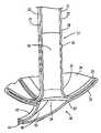
- FIG. 5is a perspective view of a stent proximal end portion comprising a retention disk in a pre-deployed configuration, in accordance with an embodiment of the present invention
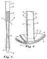
- FIG. 6is a perspective view of the stent proximal end portion comprising a retention disk in a deployed configuration, in accordance with an embodiment of the present invention.
- FIG. 7is a perspective view of the stent proximal end portion comprising a valve, in accordance with an embodiment of the present invention.
- the present inventionprovides embodiments of medical devices that provide for fluid drainage while both maintaining patient comfort.
- An embodiment of the present inventionrelates to a ureteral stent comprising an elongated tubular member having a body portion and opposed distal end portion and proximal end portion, the elongated tubular member defining a lumen therein; a retention disk comprising a plurality of generally axial, spaced-apart collapsable struts interconnected with a membrane to form a generalized tube with a retention disk lumen therein, the retention disk lumen in fluid communication with the lumen of the body portion, the struts and the membrane couple to the body portion proximal end at a retention disk distal end and terminate at a retention disk proximal end, each strut having a widthwise folding hinge substantially dividing the length of the strut, the struts adapted to have an expanded state wherein the struts are unfolded and substantially straight, as well as a free-resting state wherein each strut folds in upon itself at the folding hinge to form an inverted umbrella-like
- the inventionrelates to embodiments of medical devices (e.g., stents) for draining fluids.
- the inventionincreases patient comfort and prevents fluid retention if a stricture in a vessel develops.
- embodiments of the inventionare described herein the context of draining urine from a kidney, through a ureter, and into the bladder.
- the inventionis applicable to any situation that requires drainage within a body, from a body, and from one body structure to another.
- One such situationis, for example, biliary drainage from the gall bladder, through the biliary ducts, to the duodenum.
- FIG. 1is a front partial cross-sectional view of a ureteral stent 10 within anatomy in accordance with an embodiment of the present invention.
- the stent 10comprises an elongated tubular member 20 having a relatively straight body portion 22 and opposed distal end portion 24 and proximal end portion 28 , a retention disk 30 , and a valve 40 .
- the distal end portion 24is provided with means for retaining the distal end portion 24 in a kidney 100 , such as the conventional loop as shown.
- the body portion 22is adapted to be inserted into and reside substantially in the ureter 104 .
- FIGS. 2A , 2 B, 3 , and 4are perspective, partial perspective, partial perspective, and cross-sectional views, respectively, of the proximal end portion 28 , retention disk 30 , and valve 40 , at three-stages of deployment, in accordance with an embodiment of the present invention.
- FIGS. 2A and 2Billustrate a pre-deployment configuration, wherein the retention disk 30 is retained in an extended orientation.
- FIG. 3illustrates a partially deployed configuration, wherein the retention disk is expanding radially and contracting axially.
- FIG. 4illustrates the fully deployed, free state configuration of the retention disk 30 forming an umbrella-like configuration.
- the body portion 22comprises an elongated tubular member 20 having a wall 29 defining a lumen 26 therein.
- the tubular member 20may be formed from a variety of known materials which are biocompatible and have desired physical properties to be fabricated in the form hereafter described. Examples of suitable materials include, but not limited to, silicone, thermoplastic materials, elastomers, or any material known to one skilled in the art.
- Each strut 32is an elongated member having a widthwise folding hinge 33 substantially dividing the length of the strut 32 in half.
- the struts 32are adapted to have an expanded state wherein the struts 32 are unfolded and substantially straight, as well as a free-resting state wherein each strut 32 folds in upon itself at the folding hinge 33 to form an inverted umbrella-like disk-shaped configuration.
- the inverted umbrella-like configurationprovides a conformal shape to the ureteral orifice 101 as shown in FIG. 1 . Further, the umbrella-like configuration substantially prevents the stent 10 from irritating the trigone area of the bladder 102 . Further, the umbrella-like configuration provides a seal between the ureteral orifice 101 and the retention disk 30 , the importance of which will be discussed below with respect to the valve 40 .
- the struts 32comprise a material suitable for the particular purpose, such as, but not limited to, stainless steel and nickel-titanium alloy.
- a material suitable for the particular purposesuch as, but not limited to, stainless steel and nickel-titanium alloy.
- Certain alloys of nickel-titaniumare known as Nitinol and can be provided with a super-elastic shape-memory physical property.
- a super-elastic propertyprovides a high degree of flexibility without elastic deformation which is a desired property for the particular purpose.
- the shape-memory propertyprovides a predetermined restoring configuration also suitable for the particular purpose.
- the membrane 34comprises a relatively low durometer material. Suitable material for the membrane 34 includes, but not limited to, silicone, although other soft polymer materials could be used.
- the membrane 34comprise a material that is elastic and allows for the radially expansion of the struts 32 .
- the membrane 34comprises a non-elastic material that folds down in the pre-deployed configuration.
- the retention disk lumen 39shortens to substantially form an orifice in communication with the lumen 26 of the body portion 22 .
- the valve 40is coupled to the retention disk proximal end 37 .
- the valve 40comprises at least two valve lips 42 that couple to the retention disk proximal end 37 and converge in engagement at a valve opening 44 .
- the valve lips 42define a lumen 46 therebetween and in communication with the retention disk lumen 39 , and thus, with the lumen 26 of the body portion 22 and therefore with the kidney 100 .
- valve lips 42press together at the valve opening 44 creating a tight seal against the passage of fluids up to a certain head pressure.
- the valve lips 42are held elastically in a closed position by means of a force inherent in the shape and material of valve lips 42 and/or imparted by an elastic element (for example a thin elastic band, not shown) which exerts its force, preferably adjustable, to urge the valve lips 42 closed.
- an elastic elementfor example a thin elastic band, not shown
- valve 40When the force due to the pressure of the fluid coming from the lumen 26 on the valve lips 42 exceeds the force due to the elasticity of the materials, the valve 40 opens and the fluid exits the valve 40 and enters the bladder 102 .
- the valve 40closes when pressure in the bladder is increased, such as during voiding.
- the valve 40is functionally sealed by the valve lips 42 . This serves to stop fluid pressure waves, pulsed or otherwise, from the bladder 104 towards the kidney 100 .
- valve opening 44remains slightly open in the relaxed state to permit fluid flow and closes tightly upon increased pressure in the bladder, such as during voiding.
- At least a portion of length of the proximal end portion 28comprises a flexible portion 38 .
- the flexible portion 38is characterized by exhibiting a physical property that provides both longitudinal elasticity allowing for stretch and recoil, as well as radial elasticity allowing for bending and recovery.
- the flexible portion 38is characterized as a region having material of differing material properties than the body portion 22 .
- the body portion 22comprises a material having a less compliant material property (harder) transitioning to a more compliant (softer) material. In production, this can be accomplished by, for example, a co-extrusion process where deposition of a first material is gradually ceased and deposition of a second is gradually increased.
- the flexible portion 38is characterized as a region of thinning of the wall 21 of the tubular member 20 , wherein the tubular member 20 comprises a homogenous material.
- the body portion 22comprises a wall 21 of a predetermined thickness and the flexible portion 38 comprises a wall of a smaller predetermined thickness. In production, this can be accomplished by, for example, a co-extrusion process where deposition of a material is gradually reduced over the length of the flexible portion 38 .
- the flexible portion 38is characterized as a region of geometric change, such as, but not limited to corrugations 27 , of the wall 21 of the tubular member 20 , wherein the tubular member 20 comprises a homogenous material.
- the body portion 22comprises a wall 21 of a predetermined thickness and the flexible portion 38 comprises a wall having ripples or corrugations 27 so as to impart a more flexible property.
- a stent 10in accordance with the present invention, may comprise a valve 40 , a retention disk 30 , a flexible portion 38 , or combinations thereof.
- the stent 110comprises a body portion 22 and a valve 40 .
- the stent 110is provided with the benefits of the valve 40 .
- the stent 10includes a body portion 22 adapted to be positioned within the ureter 104 .
- the stent 10thereby provides fluid communication along its length from the distal end portion 24 to the proximal end portion 28 , and to the valve 40 ; fluid communication between the kidney 100 and bladder 102 is maintained through the stent 10 .
- a wire stylet, or guidewire,(not shown) which can be formed of stainless steel, is inserted into the valve opening 44 and retention disk 30 , the proximal end portion 28 of the stent 10 and into the lumen 26 and advanced into the distal end portion 24 .
- Confirmation that the renal pelvis has been entered by the distal end portion 24can be obtained by x-ray.
- radiopaque measurement markings or other suitable radiopaque indiciacan be incorporated on the stent 10 and are visible during x-ray examination to aid in confirming the position of the stent 10 .
- the guidewireis withdrawn, enabling the retention disk 30 to deploy.
- the retention disk 30bears against the walls of the renal cavity 101 at the ureter orifice 104 .
- the ureteral stent 10may be placed in the anatomy during surgery.
- ureteral stent 10 of the present inventionare not critical, however, they include internal diameters of 4.5 to 8.5 French, and lengths ranging from 20 cm. to 32 cm.
- the body portion 22may have, for example, a circular cross-section.
- the circular cross-sectionmay be of any circumference that is of suitable size for the body structure into which the device is placed.
- the body portion 22may be from about 8.0 French to about 4.8 French in size.
- the stent 10may have a substantially constant cross-sectional area along its length.
- the stent 10may be tapered from about the distal end portion 24 to about the proximal end portion 28 with the size of the section decreasing from about 7 French to about 3 French.
- Other French sizes and tapering configurationsare useful depending upon either the average size in a population or the actual size in an individual of the body structure or structures into which the device is placed.
- the tubular member 20may be constructed from any of a number of materials.
- materials that are usefulinclude, for example, materials that are able to flex but also retain their shape, to a degree, when they are perturbed.
- useful materialsare, for example, materials that have a resilient quality, being able to regain at least some of their original shape when the stent 10 ceases to be perturbed and/or resist, for example, compression.
- One such material that combines these featuresis PercuflexTM.
- thermo-formable materialsincluding, for example, PercuflexTM are useful in the practice of the invention.
- stentsare also applicable in the catheter and intubation arts, which include, without limitation: intravenous catheters, guiding catheters, sheaths, umbilical catheters, trocar catheters, heart catheters (including, valvostomy catheters, angioplasty catheters, arthroscopy catheters, and the like), perfusion catheters, suction catheters, oxygen catheters, endoscopy catheters, endotracheal tubes, stomach tubes, feeding tubes, lavage tubes, rectal tubes, urological tubes, irrigation tubes, aneurysm shunts, stenosis dialators, trocars, and inserters, generally.
- intravenous cathetersguiding catheters, sheaths, umbilical catheters, trocar catheters, heart catheters (including, valvostomy catheters, angioplasty catheters, arthroscopy catheters, and the like), perfusion catheters, suction catheters, oxygen catheters, endoscopy catheters, endotracheal tubes, stomach tubes, feeding tubes
Landscapes
- Health & Medical Sciences (AREA)
- Life Sciences & Earth Sciences (AREA)
- Veterinary Medicine (AREA)
- Public Health (AREA)
- General Health & Medical Sciences (AREA)
- Animal Behavior & Ethology (AREA)
- Engineering & Computer Science (AREA)
- Biomedical Technology (AREA)
- Heart & Thoracic Surgery (AREA)
- Transplantation (AREA)
- Vascular Medicine (AREA)
- Oral & Maxillofacial Surgery (AREA)
- Cardiology (AREA)
- Pulmonology (AREA)
- Gastroenterology & Hepatology (AREA)
- Urology & Nephrology (AREA)
- Ophthalmology & Optometry (AREA)
- Otolaryngology (AREA)
- Anesthesiology (AREA)
- Hematology (AREA)
- Prostheses (AREA)
- Media Introduction/Drainage Providing Device (AREA)
Abstract
Description
- The
retention disk 30 comprises a plurality of generally, axial, spaced-apartcollapsible struts 32 interconnected at their edges with a plurality of thin-wall resilientnon-permeable membranes 34 coupled to and spanning the area in between the struts, but not covering the struts, to form a generalized tube with aretention disk lumen 39 therein. Theretention disk lumen 39 is in fluid communication with thelumen 26 of the body portion22.Thestruts 32 and themembrane 34 couple to the body portionproximal end 28 at a retention diskdistal end 35 and terminate at a retention diskproximal end 37.
- The
Claims (27)
Priority Applications (3)
| Application Number | Priority Date | Filing Date | Title |
|---|---|---|---|
| US10/832,495US7470247B2 (en) | 2004-04-26 | 2004-04-26 | Ureteral stent |
| JP2004292350AJP2005312897A (en) | 2004-04-26 | 2004-10-05 | Ureteral stent |
| DE102004053543ADE102004053543A1 (en) | 2004-04-26 | 2004-11-05 | Ureteral stent |
Applications Claiming Priority (1)
| Application Number | Priority Date | Filing Date | Title |
|---|---|---|---|
| US10/832,495US7470247B2 (en) | 2004-04-26 | 2004-04-26 | Ureteral stent |
Publications (2)
| Publication Number | Publication Date |
|---|---|
| US20050240280A1 US20050240280A1 (en) | 2005-10-27 |
| US7470247B2true US7470247B2 (en) | 2008-12-30 |
Family
ID=35137520
Family Applications (1)
| Application Number | Title | Priority Date | Filing Date |
|---|---|---|---|
| US10/832,495Expired - LifetimeUS7470247B2 (en) | 2004-04-26 | 2004-04-26 | Ureteral stent |
Country Status (3)
| Country | Link |
|---|---|
| US (1) | US7470247B2 (en) |
| JP (1) | JP2005312897A (en) |
| DE (1) | DE102004053543A1 (en) |
Cited By (17)
| Publication number | Priority date | Publication date | Assignee | Title |
|---|---|---|---|---|
| US20050240141A1 (en)* | 2004-04-26 | 2005-10-27 | Peter Aliski | Stent kidney curl improvements |
| US20070156221A1 (en)* | 2003-05-26 | 2007-07-05 | Hadasit Medical Research Services And Development Company Ltd. | Stent positioning system |
| US20070198048A1 (en)* | 2005-12-23 | 2007-08-23 | Niall Behan | Medical device suitable for treating reflux from a stomach to an oesophagus |
| US20100114327A1 (en)* | 2008-06-20 | 2010-05-06 | Vysera Biomedical Limited | Valve |
| US20100114325A1 (en)* | 2008-10-22 | 2010-05-06 | Wilson-Cook Medical Inc. | Prophylactic Pancreatic Stent |
| US20100121462A1 (en)* | 2008-06-20 | 2010-05-13 | Vysera Biomedical Limited | Valve |
| US20100276769A1 (en)* | 2009-04-30 | 2010-11-04 | Infineon Technologies Ag | Semiconductor device |
| US20110144689A1 (en)* | 2009-12-15 | 2011-06-16 | Med Institute, Inc. | Occlusion Device |
| US8876800B2 (en) | 2009-12-18 | 2014-11-04 | Vysera Biomedical Limited | Urological device |
| US8992410B2 (en) | 2010-11-03 | 2015-03-31 | Vysera Biomedical Limited | Urological device |
| US9339633B2 (en) | 2010-06-11 | 2016-05-17 | Universitatsmedizin Der Johannes Gutenberg Universitat Mainz | Balloon catheter system for draining fluids from hollow organs, body cavities or cysts and/or for supplying medication |
| US9415196B2 (en) | 2013-03-13 | 2016-08-16 | Boston Scientific Scimed, Inc. | Pancreatic stent drainage system |
| US20160354113A1 (en)* | 2015-06-04 | 2016-12-08 | DePuy Synthes Products, Inc. | Surgical Cannula System and Method of Use |
| US10195066B2 (en) | 2011-12-19 | 2019-02-05 | Coloplast A/S | Luminal prosthesis and implant device |
| US11096774B2 (en) | 2016-12-09 | 2021-08-24 | Zenflow, Inc. | Systems, devices, and methods for the accurate deployment of an implant in the prostatic urethra |
| US11890213B2 (en) | 2019-11-19 | 2024-02-06 | Zenflow, Inc. | Systems, devices, and methods for the accurate deployment and imaging of an implant in the prostatic urethra |
| US12440323B2 (en) | 2021-11-10 | 2025-10-14 | Coloplast A/S | Method of delivering a urological device into a bladder neck or urethra of a user |
Families Citing this family (42)
| Publication number | Priority date | Publication date | Assignee | Title |
|---|---|---|---|---|
| WO2003002243A2 (en)* | 2001-06-27 | 2003-01-09 | Remon Medical Technologies Ltd. | Method and device for electrochemical formation of therapeutic species in vivo |
| US7507218B2 (en)* | 2004-04-26 | 2009-03-24 | Gyrus Acmi, Inc. | Stent with flexible elements |
| US8840660B2 (en) | 2006-01-05 | 2014-09-23 | Boston Scientific Scimed, Inc. | Bioerodible endoprostheses and methods of making the same |
| US8089029B2 (en) | 2006-02-01 | 2012-01-03 | Boston Scientific Scimed, Inc. | Bioabsorbable metal medical device and method of manufacture |
| JP2009538166A (en)* | 2006-05-22 | 2009-11-05 | ドゥヴォネク マリアン | Prostate stent |
| JP2010503489A (en) | 2006-09-15 | 2010-02-04 | ボストン サイエンティフィック リミテッド | Biodegradable endoprosthesis and method for producing the same |
| ES2357661T3 (en) | 2006-09-15 | 2011-04-28 | Boston Scientific Scimed, Inc. | BIOEROSIONABLE ENDOPROOTHESIS WITH BIOESTABLE INORGANIC LAYERS. |
| US20100145436A1 (en)* | 2006-09-18 | 2010-06-10 | Boston Scientific Scimed, Inc. | Bio-erodible Stent |
| ES2506144T3 (en) | 2006-12-28 | 2014-10-13 | Boston Scientific Limited | Bioerodible endoprosthesis and their manufacturing procedure |
| US8052745B2 (en) | 2007-09-13 | 2011-11-08 | Boston Scientific Scimed, Inc. | Endoprosthesis |
| US20090171465A1 (en)* | 2007-12-28 | 2009-07-02 | Boston Scientific Scimed, Inc. | Polymeric Regions For Implantable Or Insertable Medical Devices |
| US8236046B2 (en)* | 2008-06-10 | 2012-08-07 | Boston Scientific Scimed, Inc. | Bioerodible endoprosthesis |
| US7985252B2 (en)* | 2008-07-30 | 2011-07-26 | Boston Scientific Scimed, Inc. | Bioerodible endoprosthesis |
| US8382824B2 (en) | 2008-10-03 | 2013-02-26 | Boston Scientific Scimed, Inc. | Medical implant having NANO-crystal grains with barrier layers of metal nitrides or fluorides |
| EP2403546A2 (en) | 2009-03-02 | 2012-01-11 | Boston Scientific Scimed, Inc. | Self-buffering medical implants |
| US20110160839A1 (en)* | 2009-12-29 | 2011-06-30 | Boston Scientific Scimed, Inc. | Endoprosthesis |
| WO2011119603A1 (en)* | 2010-03-23 | 2011-09-29 | Boston Scientific Scimed, Inc. | Bioerodible medical implants |
| US8668732B2 (en) | 2010-03-23 | 2014-03-11 | Boston Scientific Scimed, Inc. | Surface treated bioerodible metal endoprostheses |
| US8920513B2 (en) | 2010-08-27 | 2014-12-30 | Thomas W. Rickner | Anti-refluxive and trigone sparing internal ureteral stent |
| US9445884B2 (en) | 2013-01-30 | 2016-09-20 | Boston Scientific Scimed, Inc. | Ureteral stent with drug-releasing structure |
| EP3020376A4 (en)* | 2013-07-11 | 2017-01-11 | Olympus Corporation | Stent |
| JP6523323B2 (en)* | 2014-04-11 | 2019-05-29 | コロプラスト アクティーゼルスカブ | Ureteral stent |
| CN106163604B (en)* | 2014-04-11 | 2019-11-05 | 科洛普拉斯特公司 | Ureter bracket |
| US10493232B2 (en) | 2015-07-20 | 2019-12-03 | Strataca Systems Limited | Ureteral catheters, bladder catheters, systems, kits and methods for inducing negative pressure to increase renal function |
| US11229771B2 (en) | 2015-07-20 | 2022-01-25 | Roivios Limited | Percutaneous ureteral catheter |
| US10918827B2 (en) | 2015-07-20 | 2021-02-16 | Strataca Systems Limited | Catheter device and method for inducing negative pressure in a patient's bladder |
| US10512713B2 (en) | 2015-07-20 | 2019-12-24 | Strataca Systems Limited | Method of removing excess fluid from a patient with hemodilution |
| US11040172B2 (en) | 2015-07-20 | 2021-06-22 | Strataca Systems Limited | Ureteral and bladder catheters and methods of inducing negative pressure to increase renal perfusion |
| US12064567B2 (en) | 2015-07-20 | 2024-08-20 | Roivios Limited | Percutaneous urinary catheter |
| US11040180B2 (en) | 2015-07-20 | 2021-06-22 | Strataca Systems Limited | Systems, kits and methods for inducing negative pressure to increase renal function |
| HUE049050T2 (en) | 2015-07-20 | 2020-08-28 | Strataca Systems Ltd | Ureteral and bladder catheters |
| US11541205B2 (en) | 2015-07-20 | 2023-01-03 | Roivios Limited | Coated urinary catheter or ureteral stent and method |
| US10926062B2 (en) | 2015-07-20 | 2021-02-23 | Strataca Systems Limited | Ureteral and bladder catheters and methods of inducing negative pressure to increase renal perfusion |
| US10098740B2 (en)* | 2016-07-15 | 2018-10-16 | Covidien Lp | Venous valve prostheses |
| EP3522827A4 (en)* | 2016-10-10 | 2020-07-15 | Cook Medical Technologies LLC | DEVICES AND METHODS FOR TREATING CONGESTIVE HEART FAILURE, ASCITES AND OTHER DISEASES RELATING TO EXCESSIVE BODY LIQUID |
| US10278806B2 (en)* | 2017-02-27 | 2019-05-07 | Baylor University | Ureteral stent and method |
| JP2020531159A (en) | 2017-08-25 | 2020-11-05 | ストラタカ システムズ リミテッド | Indwelling pump to facilitate removal of urine from the urinary tract |
| US10933227B2 (en)* | 2017-12-01 | 2021-03-02 | Gyrus Acmi, Inc. | Ureteral stent |
| US11083874B2 (en)* | 2018-01-24 | 2021-08-10 | Lotus Medical Technologies | Urinary catheter system with improved retaining structure and enhanced urinary drainage |
| US11318289B2 (en)* | 2018-03-30 | 2022-05-03 | Gyrus Acmi, Inc. | Ureteral stent |
| EP3581232B1 (en)* | 2018-06-11 | 2021-02-17 | Dentsply IH AB | Urethral stent and bladder control assembly comprising such a urethral stent |
| CN111249045B (en)* | 2020-01-17 | 2021-09-21 | 浙江医高医疗科技有限公司 | Improved ureteral stent system and implantation method thereof |
Citations (46)
| Publication number | Priority date | Publication date | Assignee | Title |
|---|---|---|---|---|
| US3397699A (en) | 1966-05-05 | 1968-08-20 | Gerald C. Kohl | Retaining catheter having resiliently biased wing flanges |
| US3938529A (en) | 1974-07-22 | 1976-02-17 | Gibbons Robert P | Indwelling ureteral catheter |
| US4531933A (en) | 1982-12-07 | 1985-07-30 | C. R. Bard, Inc. | Helical ureteral stent |
| US4813925A (en) | 1987-04-21 | 1989-03-21 | Medical Engineering Corporation | Spiral ureteral stent |
| US4874360A (en) | 1988-07-01 | 1989-10-17 | Medical Engineering Corporation | Ureteral stent system |
| EP0365269A1 (en) | 1988-10-17 | 1990-04-25 | VANCE PRODUCTS INCORPORATED d/b/a COOK UROLOGICAL INCORPORATED | Indwelling ureteral stent placement apparatus |
| US5073166A (en)* | 1989-02-15 | 1991-12-17 | Medical Innovations Corporation | Method and apparatus for emplacement of a gastrostomy catheter |
| US5167239A (en) | 1991-05-30 | 1992-12-01 | Endomedix Corporation | Anchorable guidewire |
| US5176625A (en) | 1990-10-25 | 1993-01-05 | Brisson A Glen | Stent for ureter |
| US5176626A (en) | 1992-01-15 | 1993-01-05 | Wilson-Cook Medical, Inc. | Indwelling stent |
| US5282860A (en) | 1991-10-16 | 1994-02-01 | Olympus Optical Co., Ltd. | Stent tube for medical use |
| EP0593948A1 (en) | 1992-10-09 | 1994-04-27 | Angiomed Ag | Stent-set |
| US5354263A (en) | 1989-01-25 | 1994-10-11 | Coll Milton E | Ureteral stent-catheter having varying diameter stent |
| US5380270A (en)* | 1990-12-07 | 1995-01-10 | Willy Rusch Ag | Ureteral catheter |
| WO1996011721A1 (en) | 1994-10-03 | 1996-04-25 | Menlo Care, Inc. | Polymeric medical device systems having shape memory |
| US5599291A (en) | 1993-01-04 | 1997-02-04 | Menlo Care, Inc. | Softening expanding ureteral stent |
| US5681274A (en) | 1995-03-31 | 1997-10-28 | Boston Scientific Corporation | Variable length uretheral stent |
| US5766209A (en)* | 1993-02-19 | 1998-06-16 | Devonec; Marian A. | Prosthesis intended for the treatment of a natural lumen or tract, in particular an endo-urethral prosthesis |
| DE69510973T2 (en) | 1994-02-25 | 2000-03-30 | Fernando Izquierdo De La Torre | Ureteral prosthesis for long-term use |
| WO2000062708A1 (en) | 1999-04-15 | 2000-10-26 | Mayo Foundation For Medical Education And Research | Multi-section stent |
| US6214036B1 (en) | 1998-11-09 | 2001-04-10 | Cordis Corporation | Stent which is easily recaptured and repositioned within the body |
| US20010053936A1 (en) | 2000-05-26 | 2001-12-20 | Whitmore Willet F. | Ureteral stent |
| US6350252B2 (en)* | 1998-01-23 | 2002-02-26 | Heartport, Inc. | Methods and devices for occluding the ascending aorta and maintaining circulation of oxygenated blood in the patient when the patient's heart is arrested |
| US6368356B1 (en) | 1996-07-11 | 2002-04-09 | Scimed Life Systems, Inc. | Medical devices comprising hydrogel polymers having improved mechanical properties |
| US6395021B1 (en) | 1997-02-26 | 2002-05-28 | Applied Medical Resources Corporation | Ureteral stent system apparatus and method |
| EP1214917A1 (en) | 2000-12-12 | 2002-06-19 | Noureddine Frid | Modular luminal endoprosthesis |
| US20020183852A1 (en) | 2001-06-01 | 2002-12-05 | Mcweeney John O. | Compressible ureteral stent for comfort |
| US20030018291A1 (en)* | 1999-12-08 | 2003-01-23 | Hill Frank C. | Ear tube and method of insertion |
| US20030040803A1 (en) | 2001-08-23 | 2003-02-27 | Rioux Robert F. | Maintaining an open passageway through a body lumen |
| WO2003030981A1 (en) | 2001-10-09 | 2003-04-17 | Scimed Life Systems, Inc. | Anti-reflux drainage devices and methods |
| DE10155767A1 (en) | 2001-11-14 | 2003-05-28 | Walter Thomas | Ureter support useful for assisting drainage of urine from the kidneys to the bladder, comprises flexible, tubular support body of resorbable material |
| US6582472B2 (en) | 1997-02-26 | 2003-06-24 | Applied Medical Resources Corporation | Kinetic stent |
| US20030163204A1 (en)* | 2000-05-26 | 2003-08-28 | Rix Gerald Henner | Stent |
| WO2003075795A1 (en) | 2002-03-07 | 2003-09-18 | Scimed Life Systems, Inc. | Ureteral stent |
| US20030176831A1 (en) | 2002-03-18 | 2003-09-18 | Gellman Barry N. | Expandable ureteral stent |
| WO2003079934A1 (en) | 2002-03-19 | 2003-10-02 | Scimed Life Systems, Inc. | Stent retention element and related methods |
| WO2003089038A1 (en) | 2002-04-16 | 2003-10-30 | Scimed Life Systems, Inc. | Ureteral stent with end-effector and related methods |
| US6709465B2 (en) | 1999-03-18 | 2004-03-23 | Fossa Medical, Inc. | Radially expanding ureteral device |
| US20040087886A1 (en)* | 2002-10-30 | 2004-05-06 | Scimed Life Systems, Inc. | Linearly expandable ureteral stent |
| US6908447B2 (en)* | 2002-04-18 | 2005-06-21 | Scimed Life Systems, Inc. | Anti-reflux ureteral stents and methods |
| US20050165366A1 (en) | 2004-01-28 | 2005-07-28 | Brustad John R. | Medical tubing having variable characteristics and method of making same |
| US6929663B2 (en)* | 2003-03-26 | 2005-08-16 | Boston Scientific Scimed, Inc. | Longitudinally expanding medical device |
| US20050240277A1 (en) | 2004-04-26 | 2005-10-27 | Peter Aliski | Stent with flexible elements |
| US20050240141A1 (en) | 2004-04-26 | 2005-10-27 | Peter Aliski | Stent kidney curl improvements |
| US20050240278A1 (en) | 2004-04-26 | 2005-10-27 | Peter Aliski | Stent improvements |
| US7041139B2 (en) | 2001-12-11 | 2006-05-09 | Boston Scientific Scimed, Inc. | Ureteral stents and related methods |
- 2004
- 2004-04-26USUS10/832,495patent/US7470247B2/ennot_activeExpired - Lifetime
- 2004-10-05JPJP2004292350Apatent/JP2005312897A/enactivePending
- 2004-11-05DEDE102004053543Apatent/DE102004053543A1/ennot_activeCeased
Patent Citations (62)
| Publication number | Priority date | Publication date | Assignee | Title |
|---|---|---|---|---|
| US3397699A (en) | 1966-05-05 | 1968-08-20 | Gerald C. Kohl | Retaining catheter having resiliently biased wing flanges |
| US3938529A (en) | 1974-07-22 | 1976-02-17 | Gibbons Robert P | Indwelling ureteral catheter |
| US4531933A (en) | 1982-12-07 | 1985-07-30 | C. R. Bard, Inc. | Helical ureteral stent |
| US4813925A (en) | 1987-04-21 | 1989-03-21 | Medical Engineering Corporation | Spiral ureteral stent |
| US4874360A (en) | 1988-07-01 | 1989-10-17 | Medical Engineering Corporation | Ureteral stent system |
| EP0516189A1 (en) | 1988-10-17 | 1992-12-02 | Vance Products Incorporated Trading As Cook Urological Incorporated | Indwelling ureteral stent placement apparatus |
| EP0365269A1 (en) | 1988-10-17 | 1990-04-25 | VANCE PRODUCTS INCORPORATED d/b/a COOK UROLOGICAL INCORPORATED | Indwelling ureteral stent placement apparatus |
| US5354263A (en) | 1989-01-25 | 1994-10-11 | Coll Milton E | Ureteral stent-catheter having varying diameter stent |
| US5073166A (en)* | 1989-02-15 | 1991-12-17 | Medical Innovations Corporation | Method and apparatus for emplacement of a gastrostomy catheter |
| US5176625A (en) | 1990-10-25 | 1993-01-05 | Brisson A Glen | Stent for ureter |
| US5380270A (en)* | 1990-12-07 | 1995-01-10 | Willy Rusch Ag | Ureteral catheter |
| US5167239A (en) | 1991-05-30 | 1992-12-01 | Endomedix Corporation | Anchorable guidewire |
| US5282860A (en) | 1991-10-16 | 1994-02-01 | Olympus Optical Co., Ltd. | Stent tube for medical use |
| US5176626A (en) | 1992-01-15 | 1993-01-05 | Wilson-Cook Medical, Inc. | Indwelling stent |
| US5518498A (en) | 1992-10-09 | 1996-05-21 | Angiomed Ag | Stent set |
| EP0593948A1 (en) | 1992-10-09 | 1994-04-27 | Angiomed Ag | Stent-set |
| US5964744A (en) | 1993-01-04 | 1999-10-12 | Menlo Care, Inc. | Polymeric medical device systems having shape memory |
| US5599291A (en) | 1993-01-04 | 1997-02-04 | Menlo Care, Inc. | Softening expanding ureteral stent |
| US5766209A (en)* | 1993-02-19 | 1998-06-16 | Devonec; Marian A. | Prosthesis intended for the treatment of a natural lumen or tract, in particular an endo-urethral prosthesis |
| DE69510973T2 (en) | 1994-02-25 | 2000-03-30 | Fernando Izquierdo De La Torre | Ureteral prosthesis for long-term use |
| WO1996011721A1 (en) | 1994-10-03 | 1996-04-25 | Menlo Care, Inc. | Polymeric medical device systems having shape memory |
| US5681274A (en) | 1995-03-31 | 1997-10-28 | Boston Scientific Corporation | Variable length uretheral stent |
| US6368356B1 (en) | 1996-07-11 | 2002-04-09 | Scimed Life Systems, Inc. | Medical devices comprising hydrogel polymers having improved mechanical properties |
| US6395021B1 (en) | 1997-02-26 | 2002-05-28 | Applied Medical Resources Corporation | Ureteral stent system apparatus and method |
| US6582472B2 (en) | 1997-02-26 | 2003-06-24 | Applied Medical Resources Corporation | Kinetic stent |
| US6350252B2 (en)* | 1998-01-23 | 2002-02-26 | Heartport, Inc. | Methods and devices for occluding the ascending aorta and maintaining circulation of oxygenated blood in the patient when the patient's heart is arrested |
| US6214036B1 (en) | 1998-11-09 | 2001-04-10 | Cordis Corporation | Stent which is easily recaptured and repositioned within the body |
| US6267783B1 (en) | 1998-11-09 | 2001-07-31 | Cordis Corporation | Stent which is easily recaptured and repositioned within the body |
| US6709465B2 (en) | 1999-03-18 | 2004-03-23 | Fossa Medical, Inc. | Radially expanding ureteral device |
| WO2000062708A1 (en) | 1999-04-15 | 2000-10-26 | Mayo Foundation For Medical Education And Research | Multi-section stent |
| US6258117B1 (en) | 1999-04-15 | 2001-07-10 | Mayo Foundation For Medical Education And Research | Multi-section stent |
| US20030018291A1 (en)* | 1999-12-08 | 2003-01-23 | Hill Frank C. | Ear tube and method of insertion |
| US20010053936A1 (en) | 2000-05-26 | 2001-12-20 | Whitmore Willet F. | Ureteral stent |
| US6764519B2 (en) | 2000-05-26 | 2004-07-20 | Scimed Life Systems, Inc. | Ureteral stent |
| US20030163204A1 (en)* | 2000-05-26 | 2003-08-28 | Rix Gerald Henner | Stent |
| EP1214917A1 (en) | 2000-12-12 | 2002-06-19 | Noureddine Frid | Modular luminal endoprosthesis |
| US20050187510A1 (en) | 2001-06-01 | 2005-08-25 | Mcweeney John O. | Compressible ureteral stent for comfort |
| WO2002098500A1 (en) | 2001-06-01 | 2002-12-12 | Scimed Life Systems, Inc. | Compressible ureteral stent for comfort |
| US6887215B2 (en) | 2001-06-01 | 2005-05-03 | Boston Scientific Scimed, Inc. | Compressible ureteral stent for comfort |
| US20020183852A1 (en) | 2001-06-01 | 2002-12-05 | Mcweeney John O. | Compressible ureteral stent for comfort |
| US20030040803A1 (en) | 2001-08-23 | 2003-02-27 | Rioux Robert F. | Maintaining an open passageway through a body lumen |
| US6921378B2 (en) | 2001-10-09 | 2005-07-26 | Boston Scientific Scimed, Inc. | Anti-reflux drainage devices and methods |
| WO2003030981A1 (en) | 2001-10-09 | 2003-04-17 | Scimed Life Systems, Inc. | Anti-reflux drainage devices and methods |
| US20050246038A1 (en) | 2001-10-09 | 2005-11-03 | O'keefe Christopher R | Anti-reflux drainage devices and methods |
| DE10155767A1 (en) | 2001-11-14 | 2003-05-28 | Walter Thomas | Ureter support useful for assisting drainage of urine from the kidneys to the bladder, comprises flexible, tubular support body of resorbable material |
| US7041139B2 (en) | 2001-12-11 | 2006-05-09 | Boston Scientific Scimed, Inc. | Ureteral stents and related methods |
| US6913625B2 (en)* | 2002-03-07 | 2005-07-05 | Scimed Life Systems, Inc. | Ureteral stent |
| WO2003075795A1 (en) | 2002-03-07 | 2003-09-18 | Scimed Life Systems, Inc. | Ureteral stent |
| US6685744B2 (en) | 2002-03-18 | 2004-02-03 | Scimed Life Systems, Inc. | Expandable ureteral stent |
| WO2003079930A1 (en) | 2002-03-18 | 2003-10-02 | Scimed Life Systems, Inc. | Expandable ureteral stent |
| US20030176831A1 (en) | 2002-03-18 | 2003-09-18 | Gellman Barry N. | Expandable ureteral stent |
| WO2003079934A1 (en) | 2002-03-19 | 2003-10-02 | Scimed Life Systems, Inc. | Stent retention element and related methods |
| US6949125B2 (en) | 2002-04-16 | 2005-09-27 | Boston Scientific Scimed, Inc. | Ureteral stent with end-effector and related methods |
| US20060015190A1 (en) | 2002-04-16 | 2006-01-19 | Robertson David W | Ureteral stent with end-effector and related methods |
| WO2003089038A1 (en) | 2002-04-16 | 2003-10-30 | Scimed Life Systems, Inc. | Ureteral stent with end-effector and related methods |
| US6908447B2 (en)* | 2002-04-18 | 2005-06-21 | Scimed Life Systems, Inc. | Anti-reflux ureteral stents and methods |
| US20040087886A1 (en)* | 2002-10-30 | 2004-05-06 | Scimed Life Systems, Inc. | Linearly expandable ureteral stent |
| US6929663B2 (en)* | 2003-03-26 | 2005-08-16 | Boston Scientific Scimed, Inc. | Longitudinally expanding medical device |
| US20050165366A1 (en) | 2004-01-28 | 2005-07-28 | Brustad John R. | Medical tubing having variable characteristics and method of making same |
| US20050240278A1 (en) | 2004-04-26 | 2005-10-27 | Peter Aliski | Stent improvements |
| US20050240277A1 (en) | 2004-04-26 | 2005-10-27 | Peter Aliski | Stent with flexible elements |
| US20050240141A1 (en) | 2004-04-26 | 2005-10-27 | Peter Aliski | Stent kidney curl improvements |
Non-Patent Citations (2)
| Title |
|---|
| Examination Report dated Aug. 4, 2006 from the German Patent Office for corresponding German patent application No. 10-2004-053-543-4-43, filed Nov. 5, 2004, 4 pages. |
| Examination Report dated Aug. 4, 2006 from the German Patent Office for related German patent application No. 10 2004 050 915.8, filed Oct. 19, 2004, 3 pages. |
Cited By (31)
| Publication number | Priority date | Publication date | Assignee | Title |
|---|---|---|---|---|
| US20070156221A1 (en)* | 2003-05-26 | 2007-07-05 | Hadasit Medical Research Services And Development Company Ltd. | Stent positioning system |
| US20050240141A1 (en)* | 2004-04-26 | 2005-10-27 | Peter Aliski | Stent kidney curl improvements |
| US20070198048A1 (en)* | 2005-12-23 | 2007-08-23 | Niall Behan | Medical device suitable for treating reflux from a stomach to an oesophagus |
| US20100036504A1 (en)* | 2005-12-23 | 2010-02-11 | Vysera Biomedical Limited | Valve |
| US9308077B2 (en) | 2005-12-23 | 2016-04-12 | Vysera Biomedical Limited | Medical device suitable for treating reflux from a stomach to an oesophagus |
| US8673020B2 (en) | 2008-06-20 | 2014-03-18 | Vysera Biomedical Limited | Esophageal valve device for placing in the cardia |
| US20100121462A1 (en)* | 2008-06-20 | 2010-05-13 | Vysera Biomedical Limited | Valve |
| US20100121461A1 (en)* | 2008-06-20 | 2010-05-13 | Vysera Biomedical Limited | Valve |
| US8029557B2 (en) | 2008-06-20 | 2011-10-04 | Vysera Biomedical Limited | Esophageal valve |
| US8500821B2 (en) | 2008-06-20 | 2013-08-06 | Vysera Biomedical Limited | Esophageal valve device for placing in the cardia |
| US20100114327A1 (en)* | 2008-06-20 | 2010-05-06 | Vysera Biomedical Limited | Valve |
| US20100114325A1 (en)* | 2008-10-22 | 2010-05-06 | Wilson-Cook Medical Inc. | Prophylactic Pancreatic Stent |
| US20100276769A1 (en)* | 2009-04-30 | 2010-11-04 | Infineon Technologies Ag | Semiconductor device |
| US20110144689A1 (en)* | 2009-12-15 | 2011-06-16 | Med Institute, Inc. | Occlusion Device |
| US9498314B2 (en) | 2009-12-18 | 2016-11-22 | Coloplast A/S | Urological device |
| US8876800B2 (en) | 2009-12-18 | 2014-11-04 | Vysera Biomedical Limited | Urological device |
| US9339633B2 (en) | 2010-06-11 | 2016-05-17 | Universitatsmedizin Der Johannes Gutenberg Universitat Mainz | Balloon catheter system for draining fluids from hollow organs, body cavities or cysts and/or for supplying medication |
| US8992410B2 (en) | 2010-11-03 | 2015-03-31 | Vysera Biomedical Limited | Urological device |
| US9585740B2 (en) | 2010-11-03 | 2017-03-07 | Coloplast A/S | Urological device |
| US10195066B2 (en) | 2011-12-19 | 2019-02-05 | Coloplast A/S | Luminal prosthesis and implant device |
| US9415196B2 (en) | 2013-03-13 | 2016-08-16 | Boston Scientific Scimed, Inc. | Pancreatic stent drainage system |
| US10357282B2 (en)* | 2015-06-04 | 2019-07-23 | Medos International Sarl | Orburator for expandable catheter |
| US20180042642A1 (en)* | 2015-06-04 | 2018-02-15 | Medos International Sarl | Obturator for Expandable Catheter |
| US9808282B2 (en)* | 2015-06-04 | 2017-11-07 | Medos International Sarl | Surgical cannula system and method of use |
| US20160354113A1 (en)* | 2015-06-04 | 2016-12-08 | DePuy Synthes Products, Inc. | Surgical Cannula System and Method of Use |
| US11096774B2 (en) | 2016-12-09 | 2021-08-24 | Zenflow, Inc. | Systems, devices, and methods for the accurate deployment of an implant in the prostatic urethra |
| US11903859B1 (en) | 2016-12-09 | 2024-02-20 | Zenflow, Inc. | Methods for deployment of an implant |
| US11998438B2 (en) | 2016-12-09 | 2024-06-04 | Zenflow, Inc. | Systems, devices, and methods for the accurate deployment of an implant in the prostatic urethra |
| US12090040B2 (en) | 2016-12-09 | 2024-09-17 | Zenflow, Inc. | Methods for deployment of an implant |
| US11890213B2 (en) | 2019-11-19 | 2024-02-06 | Zenflow, Inc. | Systems, devices, and methods for the accurate deployment and imaging of an implant in the prostatic urethra |
| US12440323B2 (en) | 2021-11-10 | 2025-10-14 | Coloplast A/S | Method of delivering a urological device into a bladder neck or urethra of a user |
Also Published As
| Publication number | Publication date |
|---|---|
| US20050240280A1 (en) | 2005-10-27 |
| JP2005312897A (en) | 2005-11-10 |
| DE102004053543A1 (en) | 2005-11-24 |
Similar Documents
| Publication | Publication Date | Title |
|---|---|---|
| US7470247B2 (en) | Ureteral stent | |
| US7507218B2 (en) | Stent with flexible elements | |
| US12310832B2 (en) | Biliary stents and methods | |
| US20050240141A1 (en) | Stent kidney curl improvements | |
| US20050240278A1 (en) | Stent improvements | |
| AU2004226434B2 (en) | Longitudinally expanding medical device | |
| EP1601313B1 (en) | Uretral stent and related methods | |
| AU2018244748B2 (en) | Stents with dual tissue-wall anchoring features | |
| CN102791316B (en) | Bracket Geometry | |
| US8511310B2 (en) | Therapeutic medical appliance delivery and method of use | |
| WO2001091668A1 (en) | Ureteral stent | |
| AU2019242546A1 (en) | Flow control valve | |
| JPH08509394A (en) | Prostheses for treatment of natural lumens or ducts such as prostheses in the urethra | |
| EP0918495A1 (en) | Device for maintaining urinary continence | |
| JP2014524292A (en) | Device for radial anal drainage of excreta from the patient's rectum and / or radial application of inflowing liquid through a catheter-like element | |
| CN110996862A (en) | Urethral plugs and systems for urinary incontinence | |
| JP2025506021A (en) | DEVICES, SYSTEMS AND METHODS FOR ENGAGEABLE STENTS - Patent application | |
| HK40027622A (en) | Urethral plug and system for addressing urinary incontinence | |
| JPH03176074A (en) | Fastener to be set in body cavity |
Legal Events
| Date | Code | Title | Description |
|---|---|---|---|
| AS | Assignment | Owner name:ACMI CORPORATION, MASSACHUSETTS Free format text:ASSIGNMENT OF ASSIGNORS INTEREST;ASSIGNORS:ALISKI, MR. PETER;TREMAGLIO, MR. ANTHONY;NISHTALA, MR. VASU;AND OTHERS;REEL/FRAME:014775/0190;SIGNING DATES FROM 20040518 TO 20040608 | |
| AS | Assignment | Owner name:ANTARES CAPITAL CORPORATION, AS AGENT, ILLINOIS Free format text:SECURITY AGREEMENT;ASSIGNOR:ACMI CORPORATION;REEL/FRAME:015594/0669 Effective date:20040715 | |
| AS | Assignment | Owner name:ACMI CORPORATION, MASSACHUSETTS Free format text:RELASE OF SECURITY AGREEMENT;ASSIGNOR:ANTARES CAPITAL CORPORATION;REEL/FRAME:016309/0574 Effective date:20050721 | |
| AS | Assignment | Owner name:THE GOVERNOR AND COMPANY OF THE BANK OF SCOTLAND, Free format text:SECURITY AGREEMENT;ASSIGNOR:ACMI CORPORATION;REEL/FRAME:016418/0218 Effective date:20050804 | |
| AS | Assignment | Owner name:GYRUS ACMI, INC., MASSACHUSETTS Free format text:CHANGE OF NAME;ASSIGNOR:ACMI CORPORATION;REEL/FRAME:020647/0862 Effective date:20070110 | |
| STCF | Information on status: patent grant | Free format text:PATENTED CASE | |
| FPAY | Fee payment | Year of fee payment:4 | |
| AS | Assignment | Owner name:GYRUS ACMI, INC., MASSACHUSETTS Free format text:ASSIGNMENT OF ASSIGNORS INTEREST;ASSIGNOR:BANK OF SCOTLAND;REEL/FRAME:030422/0113 Effective date:20130419 | |
| FPAY | Fee payment | Year of fee payment:8 | |
| MAFP | Maintenance fee payment | Free format text:PAYMENT OF MAINTENANCE FEE, 12TH YEAR, LARGE ENTITY (ORIGINAL EVENT CODE: M1553); ENTITY STATUS OF PATENT OWNER: LARGE ENTITY Year of fee payment:12 |