US7469619B2 - Electronic torque wrench with a torque compensation device - Google Patents
Electronic torque wrench with a torque compensation deviceDownload PDFInfo
- Publication number
- US7469619B2 US7469619B2US11/486,693US48669306AUS7469619B2US 7469619 B2US7469619 B2US 7469619B2US 48669306 AUS48669306 AUS 48669306AUS 7469619 B2US7469619 B2US 7469619B2
- Authority
- US
- United States
- Prior art keywords
- wrench
- wrench head
- torque
- processor
- sensing device
- Prior art date
- Legal status (The legal status is an assumption and is not a legal conclusion. Google has not performed a legal analysis and makes no representation as to the accuracy of the status listed.)
- Active, expires
Links
Images


Classifications
- B—PERFORMING OPERATIONS; TRANSPORTING
- B25—HAND TOOLS; PORTABLE POWER-DRIVEN TOOLS; MANIPULATORS
- B25B—TOOLS OR BENCH DEVICES NOT OTHERWISE PROVIDED FOR, FOR FASTENING, CONNECTING, DISENGAGING OR HOLDING
- B25B23/00—Details of, or accessories for, spanners, wrenches, screwdrivers
- B25B23/0007—Connections or joints between tool parts
- B25B23/0021—Prolongations interposed between handle and tool
- B—PERFORMING OPERATIONS; TRANSPORTING
- B25—HAND TOOLS; PORTABLE POWER-DRIVEN TOOLS; MANIPULATORS
- B25B—TOOLS OR BENCH DEVICES NOT OTHERWISE PROVIDED FOR, FOR FASTENING, CONNECTING, DISENGAGING OR HOLDING
- B25B23/00—Details of, or accessories for, spanners, wrenches, screwdrivers
- B25B23/14—Arrangement of torque limiters or torque indicators in wrenches or screwdrivers
- B25B23/142—Arrangement of torque limiters or torque indicators in wrenches or screwdrivers specially adapted for hand operated wrenches or screwdrivers
- B25B23/1422—Arrangement of torque limiters or torque indicators in wrenches or screwdrivers specially adapted for hand operated wrenches or screwdrivers torque indicators or adjustable torque limiters
- B25B23/1425—Arrangement of torque limiters or torque indicators in wrenches or screwdrivers specially adapted for hand operated wrenches or screwdrivers torque indicators or adjustable torque limiters by electrical means
Definitions
- the present inventionrelates generally to electronic torque wrenches and extensions for use therewith. More particularly, the present invention relates to a device for use with torque wrenches that identifies an extension being used with the wrench and compensates displayed torque values accordingly.
- fasteners used to assemble performance critical componentsrequire tightening to a specified torque level.
- a popular method of tightening such fastenersis through the use of a torque wrench. The accuracy and reliability of these wrenches is important to insuring that the fasteners are properly tightened the specified torque levels.
- Torque wrenchesvary from simple mechanical types to sophisticated electronic types. Mechanical type torque wrenches are generally less expensive than electronic ones. There are two common types of mechanical torque wrenches, beam and clicker types. With beam type torque wrenches, a beam bends relative to a non-deflecting beam in response to the torque applied. The amount of deflection of the bending beam relative to the stationary beam is indicative of the torque applied. Clicker type torque wrenches work by pre-loading a snap mechanism with a spring to release at a specified torque, thereby generating a click noise.
- ETWElectronic torque wrenches
- torque extensionsmay be required to tighten fasteners that are in locations that the torque wrench will not reach.
- One of the most common methods of attaching a torque extension to an ETWis to replace the original drive head with an extension that has its own drive head. Once the extension is inserted, the readings of the ETW must usually be corrected for any change in lever arm length due to the extension. With the extension in place, the actual torque experienced by the fastener will be either higher or lower than what is actually displayed on the ETW, depending on whether the extension extends outwardly or inwardly from the end of the ETW, respectively.
- a different correction factorFor each different length extension, a different correction factor must be calculated. Typically, the end user calculates a correction factor and either divides or multiplies the desired final actual torque value to be applied to the fastener by this correction factor to determine the final compensated set torque value (as displayed by the ETW) that is to be input into the ETW. Whether the actual torque value is divided by or multiplied by the correction factor is dependent upon the method of determining the correction factor.
- the final compensated set torque valueis the value at which, when displayed, the user ceases to apply torque to the fastener. Typically, the user will only know the final compensated set torque value accurately and is not able to accurately determine the intermediate torque values.
- the useronly calculates the final compensated set torque value for the set torque and will not be able to continuously monitor the actual torque values during torquing operations as only “compensated” values are displayed by the ETW. This situation can lead to over and under-torquing, possibly resulting in loss of performance of the fasteners.
- the present inventionrecognizes and addresses the foregoing considerations, and others, of prior art constructions and methods.
- One embodiment of the present inventionprovides an electronic torque wrench for driving a workpiece, the torque wrench including a wrench body having a handle end and a wrench head receiving end.
- a wrench headincludes a workpiece receiving end and a mounting end that is removably received by the wrench head receiving end of the wrench body.
- a user interfaceincluding a processor and a display is routed on the wrench body.
- a wrench head sensing deviceis carried by the wrench head receiving end and includes an electrical connection between the wrench head sensing device and the processor so that the wrench head sensing device can send an electrical signal to the processor indicating the presence of the wrench head on the wrench head receiving end.
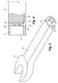
- FIG. 1is a partially cut-away top view of an electronic torque wrench including a torque compensation device in accordance with an embodiment of the present invention
- FIGS. 2A through 2Care partially cut-away top views of the electronic torque wrench as shown in FIG. 1 , including a variety of different extensions;
- FIG. 3is a perspective view of a spanner head extension for use with the electronic torque wrench as shown in FIG. 1 ;
- FIG. 4is a partial cross-sectional side view of the socket of the electronic torque wrench as shown in FIG. 1 , taken along line 4 - 4 ;
- FIG. 5is a schematic of an electronic circuit of the torque compensation device as shown in FIG. 1 ;
- FIG. 6is a schematic diagram of an electronic circuit of the torque compensation device as shown in FIG. 1 ;
- FIG. 7is a schematic diagram of the electronic circuit of the torque compensation device integrated with the electronic circuit of the electronic torque wrench as shown in FIG. 1 .
- the electronic torque wrench 10includes a wrench body 12 , a ratchet/wrench head 14 , an extension sensor probe 16 , and an electronic unit 18 .
- the wrench body 12is of tubular construction, made of steel or other rigid material, and houses a strain tensor for measuring torque applied by torque wrench 10 to a fastener.
- a socket 20typically of rectangular or square cross-section, accepts a correspondingly shaped projection, or mounting boss 22 , on wrench head 14 , or alternatively, a torque extension.
- Extensions 24 and 26 shown in FIGS. 2A and 2Brespectively, include spanner wrench ends 30 for engaging a fastener 31
- extension 28 shown in FIG. 2Cincludes a ratchet head 32 for engaging a fastener.
- Other extensions that can be usedcan include a ratcheting square drive head, a box-end wrench head, a hex drive head, a square drive head, a socket, etc.
- the rectangular cross-section of socket 20is only a preferred embodiment and sockets with other cross-sectional shapes are within the scope of this invention.
- extension 24includes mounting boss 22 that is rectangular in cross-section and wrench body 12 includes a correspondingly shaped socket 20 .
- mounting boss 22is inserted into socket 20 of wrench body 12 until a spring loaded detent pin 34 on the projection snaps into a corresponding aperture 36 ( FIG. 4 ) formed in the wall of socket 20 .
- Wrench body 12includes a hand gripper 38 at its distal end for allowing the user to comfortably grasp and operate wrench 10 .
- Electronic unit 18is mounted to wrench body 12 between hand gripper 38 and the drive end.
- Electronic unit 18includes electronic circuits ( FIGS. 5 through 7 ) to receive signals from the strain tensor and convert them to equivalent torque values being applied by torque wrench 10 at wrench head 14 .
- Electronic unit 18includes the electronic circuitry of the torque compensation device as well as a printed circuit board (not shown) with electronic components, a liquid crystal display (LCD) 39 , batteries (not shown), and a switch bank 40 .
- LCDliquid crystal display
- inventions shown in FIGS. 2A through 2Care all extensions that are inserted after removing the standard wrench head 14 with which electronic torque wrench 10 is designed to provide torque measurements with.
- embodiments of electronic torque wrenchescan have integrated ratchet heads as part of the strain tensor which are not removable.
- embodiments of the inventioncan be configured to work with a torque wrench having an integrated ratchet head.
- various embodimentsinclude contact switches mounted on the drive boss of the wrench head that are switched on or off when an extension having a socket with a unique pattern of projections is mounted on the drive boss.
- Torque extension 24including a spanner head 30 is shown.
- Torque extension 24includes mounting boss 22 with a spring loaded pin 34 for engaging aperture 36 ( FIG. 4 ) formed in the wall of socket 20 on wrench body 12 .
- the extension's mounting boss 22has a rectangular cross-section including up to four detent projections 44 extending outwardly therefrom that correspond to four contact switches 46 a, 46 b, 46 c and 46 d on extension sensor probe 16 ( FIG. 4 ) mounted in socket 20 of wrench body 12 .
- Mounting projection 22 of spanner extension 24includes one of the four possible detent projections 44 a extending therefrom that identifies the torque extension to the torque compensation device as Extension-1000, or Extension-8 (see Table 1). Since there are four contact switches in the preferred embodiment, it is possible to uniquely identify up to 16 torque extensions (2 to the power of 4) that can be automatically detected so that the displayed torque values may be compensated for.
- An example list of possible extensionsis shown in Table 1. Of the sixteen extensions, the first one (Extension-0/Extension-0000) is reserved for the standard ratchet head 14 shown in FIG. 1 , leaving a total of fifteen extensions that can be uniquely identified by the torque compensation device.
- the number of extensions that can be automatically detectedcan be increased by increasing both the number of contact switches 46 and detent projections 44 . For example, the number of extensions that can be automatically detected can be increased to 32 if the number of contact switches 46 and detent projections 44 is increased to five each (2 to the power of 5).
- FIG. 4shows a close up view of socket 20 formed in wrench body 12 with extension sensor probe 16 mounted therein.
- socket 20is of rectangular cross-section with aperture 36 configured to receive spring-loaded detent pin 34 on the standard ratchet head and extensions.
- Sensor probe 16includes a printed circuit board (PCB) 48 with contact switches 46 mounted thereon.
- PCB 48printed circuit board
- the entire unitis preferably encapsulated in a soft polymer material (not shown for ease of description) that is sealed to prevent entry of foreign material, yet allows each contact switch to operate independently of the remaining switches.
- the four contact switches on PCB 48are normally inactive.
- FIG. 5shows an electronic circuit of the torque compensation device.
- each switchis active-low (i.e., normally closed with a high signal and opens when activated with a low signal).
- a debouncing circuit 47can be added to the contact switches to eliminate multiple signals when an extension is first inserted, as shown in FIG. 6 .
- the debouncing featureadds a low-pass filter that filters out rapidly alternating voltage levels caused by multiple unintended contacts with a switch.
- the low pass filterfilters out high frequency changes in voltage levels. For example, when inserting an extension into the socket of the wrench, it is possible that the user could inadvertently depress an improper switch temporarily. When a switch is pressed, for example, for one tenth of a second, the processor may actually sample this signal many thousands of times. This feature is used to avoid getting false readings as to which switches are actually depressed by insertion of the extension, thereby insuring proper identification of the extension.
- the four contact switch signalsare connected to a digital interface circuit 60 that provides power and buffers the input signals. The digital signals are then input to a microcontroller unit 62 .
- FIG. 7is a schematic diagram of the electronic circuit of the torque compensation device incorporated into the electronic circuit of the electronic torque wrench shown in FIG. 1 .
- detent projections 44 on mounting boss 22 of the extension and contact switches 46 on extension sensor probe 16 mounted in socket 20 of wrench body 12is used in the preferred embodiment of this invention for illustration purposes. It will be understood by those skilled in the art that the basic function of sensing the torque extension can be done with other types of combinations, such as inserts having varying material properties from one to the next can be mounted on the mounting boss of the extension and optical, magnetic, hall-effect, inductance, capacitance, etc., sensors can be included in the socket of the wrench body for identifying the various materials based on their properties, therefore identifying the extension.
- the torque compensation devicedetermines the extension number of the extension that has been inserted in the torque wrench and displays the extension number on LCD 39 ( FIG. 1 ) for the user to see and verify.
- L Eis the distance between the center point of hand gripper 38 and the center of the fastener to be torqued with the torque extension (Extension-1 through Extension-15 in the present case); and L O is the distance between the center of hand gripper 38 and the center of the fastener if standard ratchet head 14 (also called Extension-0 in the present case) were being used.
- the compensated torque value actually applied to the fastener with the torque extensionis then output to electronic unit 18 that displays the current compensated actual torque value on LCD 39 . Also, if selected, a peak hold feature records the maximum actual torque value reached during the torquing of the fastener and displays the value on LCD 39 .
Landscapes
- Engineering & Computer Science (AREA)
- Mechanical Engineering (AREA)
- Details Of Spanners, Wrenches, And Screw Drivers And Accessories (AREA)
Abstract
Description
T
where (T
| TABLE 1 | ||||||
| Name | A | B | C | D | ||
| Extension-0/Extension-0000 | 0 | 0 | 0 | 0 | ||
| Extension-1/Extension-0001 | 0 | 0 | 0 | 1 | ||
| Extension-2/Extension-0010 | 0 | 0 | 1 | 0 | ||
| Extension-3/Extension-0011 | 0 | 0 | 1 | 1 | ||
| Extension-4/Extension-0100 | 0 | 1 | 0 | 0 | ||
| Extension-5/Extension-0101 | 0 | 1 | 0 | 1 | ||
| Extension-6/Extension-0110 | 0 | 1 | 1 | 0 | ||
| Extension-7/Extension-0111 | 0 | 1 | 1 | 1 | ||
| Extension-8/Extension-1000 | 1 | 0 | 0 | 0 | ||
| Extension-9/Extension-1001 | 1 | 0 | 0 | 1 | ||
| Extension-10/Extension-1010 | 1 | 0 | 1 | 0 | ||
| Extension-11/Extension-1011 | 1 | 0 | 1 | 1 | ||
| Extension-12/Extension-1100 | 1 | 1 | 0 | 0 | ||
| Extension-13/Extension-1101 | 1 | 1 | 0 | 1 | ||
| Extension-14/Extension-1110 | 1 | 1 | 1 | 0 | ||
| Extension-15/Extension-1111 | 1 | 1 | 1 | 1 | ||
Claims (18)
Priority Applications (1)
| Application Number | Priority Date | Filing Date | Title |
|---|---|---|---|
| US11/486,693US7469619B2 (en) | 2005-07-18 | 2006-07-14 | Electronic torque wrench with a torque compensation device |
Applications Claiming Priority (2)
| Application Number | Priority Date | Filing Date | Title |
|---|---|---|---|
| US70013105P | 2005-07-18 | 2005-07-18 | |
| US11/486,693US7469619B2 (en) | 2005-07-18 | 2006-07-14 | Electronic torque wrench with a torque compensation device |
Publications (2)
| Publication Number | Publication Date |
|---|---|
| US20070119267A1 US20070119267A1 (en) | 2007-05-31 |
| US7469619B2true US7469619B2 (en) | 2008-12-30 |
Family
ID=38086138
Family Applications (1)
| Application Number | Title | Priority Date | Filing Date |
|---|---|---|---|
| US11/486,693Active2026-10-14US7469619B2 (en) | 2005-07-18 | 2006-07-14 | Electronic torque wrench with a torque compensation device |
Country Status (1)
| Country | Link |
|---|---|
| US (1) | US7469619B2 (en) |
Cited By (21)
| Publication number | Priority date | Publication date | Assignee | Title |
|---|---|---|---|---|
| US20080208522A1 (en)* | 2007-02-22 | 2008-08-28 | Michael Lucke | Angle measuring device |
| US20090107306A1 (en)* | 2007-10-25 | 2009-04-30 | Hsuan-Sen Shiao | Electronic torque wrench having a trip unit |
| US20100147118A1 (en)* | 2006-03-20 | 2010-06-17 | Chih-Ching Hsieh | Double-fulcrum torque wrench |
| US20100206141A1 (en)* | 2007-06-13 | 2010-08-19 | Kyoto Tool Co., Ltd. | Torque wrench |
| US20110132157A1 (en)* | 2009-12-09 | 2011-06-09 | David Duvan | Electromechanical wrench |
| CN102179791A (en)* | 2010-01-04 | 2011-09-14 | 阿派克斯布兰兹股份有限公司 | Ratcheting device for an electronic torque wrench |
| US20110283845A1 (en)* | 2010-05-21 | 2011-11-24 | Taken Etorque Technology Co., Ltd. | Extensive Apparatus for a Wrench |
| US20110303054A1 (en)* | 2008-09-23 | 2011-12-15 | Atlas Copco Blm S.R.L. | Fastening apparatus with interchangeable programmable inserts |
| US8091438B1 (en)* | 2010-10-15 | 2012-01-10 | Taken Etorque Technology Co., Ltd. | Torsion tool |
| US20120006161A1 (en)* | 2010-07-12 | 2012-01-12 | Legend Lifestyle Products Corp. | Wireless transmission torque wrench with angular orientation correction |
| US20120312132A1 (en)* | 2011-06-10 | 2012-12-13 | Ming-Hua Li | Electronic torque apparatus eqipped with an automatic compensation device with output torque |
| US8485075B1 (en)* | 2010-05-18 | 2013-07-16 | Gauthier Biomedical, Inc. | Electronic torque wrench |
| US20140068909A1 (en)* | 2012-09-10 | 2014-03-13 | Kabo Tool Company | Torque Wrench and Method of Operating the Same |
| US20140069243A1 (en)* | 2012-09-10 | 2014-03-13 | Kabo Tool Company | Torque Wrench |
| US20140331828A1 (en)* | 2013-05-07 | 2014-11-13 | Jerry A. King | Method of Compensating for Adapters or Extensions on an Electronic Torque Wrench |
| US20150336247A1 (en)* | 2014-05-21 | 2015-11-26 | Pervasive Engineering | Torque wrench adapter |
| US9358672B2 (en) | 2010-05-18 | 2016-06-07 | Gauthier Biomedical, Inc. | Electronic torque wrench |
| US20170348836A1 (en)* | 2016-06-07 | 2017-12-07 | Bobby Hu | Torque Wrench |
| TWI625202B (en)* | 2017-06-12 | 2018-06-01 | 優鋼機械股份有限公司 | An electronic torque wrench with a sensing structure |
| US10562161B2 (en)* | 2018-01-05 | 2020-02-18 | General Electric Company | Torque wrench |
| USD1014208S1 (en) | 2023-09-22 | 2024-02-13 | Dustin Martin | Collet nut torque adapter |
Families Citing this family (18)
| Publication number | Priority date | Publication date | Assignee | Title |
|---|---|---|---|---|
| US7370539B2 (en)* | 2005-07-18 | 2008-05-13 | Easco Hand Tools, Inc. | Electronic torque wrench with a rotatable indexable display device |
| US20080111703A1 (en)* | 2006-11-13 | 2008-05-15 | Chih-Ching Hsieh | Alarm device of twisting bending spanner |
| TWM325900U (en)* | 2007-05-30 | 2008-01-21 | Boundless Lin Co Ltd | Torsion wrench capable of displaying detected torsion |
| US7685889B2 (en)* | 2008-01-14 | 2010-03-30 | Chih-Ching Hsieh | Multi-function digital tool |
| ITMI20080462A1 (en)* | 2008-03-18 | 2009-09-19 | Atlas Copco Blm Srl | "ELECTRONIC DYNAMOMETRIC KEY WITH REPLACEABLE TORQUE SENSORS" |
| US8844381B2 (en) | 2009-04-03 | 2014-09-30 | Apex Brands, Inc. | Electronic torque wrench with dual tension beam |
| GB2470228A (en)* | 2009-05-15 | 2010-11-17 | Crane Electronics | Electronic Torque Wrench with Click Mechanism |
| US20110048182A1 (en)* | 2009-09-02 | 2011-03-03 | Acument Intellectual Properties, Llc | Torque limiting socket and method of using same |
| ITBA20120035A1 (en)* | 2012-05-29 | 2013-11-30 | Eclatorq Technology Co Ltd | ELECTRONIC TORQUE EQUIPMENT EQUIPPED WITH AN AUTOMATIC OUTPUT TORQUE COMPENSATION DEVICE |
| US20140316421A1 (en)* | 2013-04-23 | 2014-10-23 | RL Inventions, LLC | Method and tool with integrated inclinometer |
| US11524395B2 (en)* | 2018-04-10 | 2022-12-13 | Panasonic Intellectual Property Management Co., Ltd. | Signal processing apparatus and electric tool |
| DE102021127081A1 (en) | 2021-10-19 | 2023-04-20 | Bayerische Motoren Werke Aktiengesellschaft | Method for operating a screwing tool, in particular a hand-held screwing tool |
| USD1091276S1 (en)* | 2022-05-03 | 2025-09-02 | Atlas Copco Industrial Technique Ab | Torque wrench |
| CA220341S (en)* | 2022-07-06 | 2024-04-25 | Hoffmann Eng Services Gmbh | Torque wrench |
| CN120152816A (en)* | 2022-09-01 | 2025-06-13 | 艾沛克斯品牌公司 | Electronic torque wrench with automatic lever length measurement |
| USD1078418S1 (en)* | 2023-02-02 | 2025-06-10 | Stanley Black & Decker Mea Fze | Digital torque wrench |
| USD1067739S1 (en)* | 2023-09-14 | 2025-03-25 | Wuxi Xinlite Precision Technology Co., Ltd. | Digital torque wrench |
| DE102024100847A1 (en)* | 2024-01-12 | 2025-07-17 | Wera Werkzeuge Gmbh | Calibration of a torque wrench using machine-readable codes |
Citations (26)
| Publication number | Priority date | Publication date | Assignee | Title |
|---|---|---|---|---|
| US4257263A (en) | 1978-07-01 | 1981-03-24 | Werkzeug-Union Gmbh-Dwu | Torque wrench |
| US4397196A (en) | 1979-08-29 | 1983-08-09 | Lemelson Jerome H | Electronic tool and method |
| US4558601A (en) | 1984-01-06 | 1985-12-17 | J. S. Technology, Inc. | Digital indicating torque wrench |
| US4641538A (en) | 1984-07-23 | 1987-02-10 | Forges Stephanoises S.A. | Lightweight electronic torque wrench |
| US4643030A (en) | 1985-01-22 | 1987-02-17 | Snap-On Tools Corporation | Torque measuring apparatus |
| US5315501A (en) | 1992-04-03 | 1994-05-24 | The Stanley Works | Power tool compensator for torque overshoot |
| US5537877A (en) | 1995-09-20 | 1996-07-23 | Frank Hsu | Torsion wrench with display unit for displaying torsion force limit thereon |
| US5589644A (en) | 1994-12-01 | 1996-12-31 | Snap-On Technologies, Inc. | Torque-angle wrench |
| US6070506A (en) | 1998-07-20 | 2000-06-06 | Snap-On Tools Company | Ratchet head electronic torque wrench |
| US6119562A (en) | 1999-07-08 | 2000-09-19 | Jenkins; Bradley G. | Electromechanical releasing torque wrench |
| US6167788B1 (en) | 1996-09-12 | 2001-01-02 | Saltus-Werk Max Forst Gmbh | Torque Wrench |
| US6234051B1 (en)* | 1999-06-16 | 2001-05-22 | Blm S.A.S. Di L. Bareggi & C. | Tightening tool with interchangeable inserts |
| US6345436B1 (en) | 1999-06-22 | 2002-02-12 | Ernest Richardson Codrington | Combination torque tool and method of adjusting valves and injectors |
| US20020170395A1 (en) | 2001-05-18 | 2002-11-21 | Nai-Jane Wang | Electronic type torsional wrench |
| US20020178876A1 (en) | 2001-05-18 | 2002-12-05 | Nai-Jane Wang | Electronic type torsional wrench |
| US6526853B2 (en) | 2001-01-31 | 2003-03-04 | Bradley G. Jenkins | Electromechanical releasing torque wrench |
| US6698298B2 (en) | 2000-08-07 | 2004-03-02 | Tohnichi Mfg. Co., Ltd. | Torque wrench for further tightening inspection |
| US20040255733A1 (en) | 2003-05-01 | 2004-12-23 | Reynertson John L. | Digital torque wrench |
| US20050061119A1 (en) | 2002-10-16 | 2005-03-24 | Becker Thomas P. | Ratcheting torque-angle wrench and method |
| US20050072278A1 (en) | 2003-10-03 | 2005-04-07 | Brian Cutler | Ergonomic electronic torque wrench |
| US20050092143A1 (en) | 2004-07-30 | 2005-05-05 | Lehnert Mark W. | Position sensing electronic torque wrench |
| US20050223856A1 (en) | 2004-04-07 | 2005-10-13 | John Reynertson | Torque wrench with fastener indicator and system and method employing same |
| US6968759B2 (en) | 2001-11-14 | 2005-11-29 | Snap-On Incorporated | Electronic torque wrench |
| US7000508B2 (en) | 2004-01-16 | 2006-02-21 | Industrial Technology Research Institute | Device for numerically displaying torque of torque wrench having a preset maximum torque |
| US7047849B2 (en) | 2004-01-22 | 2006-05-23 | King Tony Tools Co., Ltd. | Wrench capable of counting the number of times its torque reaches set values |
| US7089834B2 (en) | 2004-04-07 | 2006-08-15 | Ryeson Corporation | Torque wrench with torque range indicator and system and method employing the same |
- 2006
- 2006-07-14USUS11/486,693patent/US7469619B2/enactiveActive
Patent Citations (30)
| Publication number | Priority date | Publication date | Assignee | Title |
|---|---|---|---|---|
| US4257263A (en) | 1978-07-01 | 1981-03-24 | Werkzeug-Union Gmbh-Dwu | Torque wrench |
| US4397196A (en) | 1979-08-29 | 1983-08-09 | Lemelson Jerome H | Electronic tool and method |
| US4558601A (en) | 1984-01-06 | 1985-12-17 | J. S. Technology, Inc. | Digital indicating torque wrench |
| US4641538A (en) | 1984-07-23 | 1987-02-10 | Forges Stephanoises S.A. | Lightweight electronic torque wrench |
| US4643030A (en) | 1985-01-22 | 1987-02-17 | Snap-On Tools Corporation | Torque measuring apparatus |
| US5315501A (en) | 1992-04-03 | 1994-05-24 | The Stanley Works | Power tool compensator for torque overshoot |
| US5589644A (en) | 1994-12-01 | 1996-12-31 | Snap-On Technologies, Inc. | Torque-angle wrench |
| US5537877A (en) | 1995-09-20 | 1996-07-23 | Frank Hsu | Torsion wrench with display unit for displaying torsion force limit thereon |
| US6167788B1 (en) | 1996-09-12 | 2001-01-02 | Saltus-Werk Max Forst Gmbh | Torque Wrench |
| US6070506A (en) | 1998-07-20 | 2000-06-06 | Snap-On Tools Company | Ratchet head electronic torque wrench |
| US6234051B1 (en)* | 1999-06-16 | 2001-05-22 | Blm S.A.S. Di L. Bareggi & C. | Tightening tool with interchangeable inserts |
| US6345436B1 (en) | 1999-06-22 | 2002-02-12 | Ernest Richardson Codrington | Combination torque tool and method of adjusting valves and injectors |
| US6119562A (en) | 1999-07-08 | 2000-09-19 | Jenkins; Bradley G. | Electromechanical releasing torque wrench |
| US6276243B1 (en) | 1999-07-08 | 2001-08-21 | Bradley G. Jenkins | Electromechanical releasing torque wrench |
| US6698298B2 (en) | 2000-08-07 | 2004-03-02 | Tohnichi Mfg. Co., Ltd. | Torque wrench for further tightening inspection |
| US6526853B2 (en) | 2001-01-31 | 2003-03-04 | Bradley G. Jenkins | Electromechanical releasing torque wrench |
| US20020170395A1 (en) | 2001-05-18 | 2002-11-21 | Nai-Jane Wang | Electronic type torsional wrench |
| US20020178876A1 (en) | 2001-05-18 | 2002-12-05 | Nai-Jane Wang | Electronic type torsional wrench |
| US6981436B2 (en) | 2001-11-14 | 2006-01-03 | Snap-On Incorporated | Electronic torque wrench |
| US6968759B2 (en) | 2001-11-14 | 2005-11-29 | Snap-On Incorporated | Electronic torque wrench |
| US20050061119A1 (en) | 2002-10-16 | 2005-03-24 | Becker Thomas P. | Ratcheting torque-angle wrench and method |
| US7082866B2 (en) | 2002-10-16 | 2006-08-01 | Snap-On Incorporated | Ratcheting torque-angle wrench and method |
| US20040255733A1 (en) | 2003-05-01 | 2004-12-23 | Reynertson John L. | Digital torque wrench |
| US7082865B2 (en) | 2003-05-01 | 2006-08-01 | Ryeson Corporation | Digital torque wrench |
| US20050072278A1 (en) | 2003-10-03 | 2005-04-07 | Brian Cutler | Ergonomic electronic torque wrench |
| US7000508B2 (en) | 2004-01-16 | 2006-02-21 | Industrial Technology Research Institute | Device for numerically displaying torque of torque wrench having a preset maximum torque |
| US7047849B2 (en) | 2004-01-22 | 2006-05-23 | King Tony Tools Co., Ltd. | Wrench capable of counting the number of times its torque reaches set values |
| US20050223856A1 (en) | 2004-04-07 | 2005-10-13 | John Reynertson | Torque wrench with fastener indicator and system and method employing same |
| US7089834B2 (en) | 2004-04-07 | 2006-08-15 | Ryeson Corporation | Torque wrench with torque range indicator and system and method employing the same |
| US20050092143A1 (en) | 2004-07-30 | 2005-05-05 | Lehnert Mark W. | Position sensing electronic torque wrench |
Cited By (35)
| Publication number | Priority date | Publication date | Assignee | Title |
|---|---|---|---|---|
| US7942085B2 (en)* | 2006-03-20 | 2011-05-17 | Chih-Ching Hsieh | Double-fulcrum torque wrench |
| US20100147118A1 (en)* | 2006-03-20 | 2010-06-17 | Chih-Ching Hsieh | Double-fulcrum torque wrench |
| US7841100B2 (en)* | 2007-02-22 | 2010-11-30 | Eduard Wille Gmbh & Co Kg | Angle measuring device |
| US20080208522A1 (en)* | 2007-02-22 | 2008-08-28 | Michael Lucke | Angle measuring device |
| US20100206141A1 (en)* | 2007-06-13 | 2010-08-19 | Kyoto Tool Co., Ltd. | Torque wrench |
| US8234936B2 (en)* | 2007-06-13 | 2012-08-07 | Hosiden Corporation | Torque wrench having improved tightening torque measurement value |
| US7540220B2 (en)* | 2007-10-25 | 2009-06-02 | Hsuan-Sen Shiao | Electronic torque wrench having a trip unit |
| US20090107306A1 (en)* | 2007-10-25 | 2009-04-30 | Hsuan-Sen Shiao | Electronic torque wrench having a trip unit |
| US20110303054A1 (en)* | 2008-09-23 | 2011-12-15 | Atlas Copco Blm S.R.L. | Fastening apparatus with interchangeable programmable inserts |
| US8555755B2 (en)* | 2008-09-23 | 2013-10-15 | Atlas Copco Blm S.R.L. | Fastening apparatus with interchangeable programmable inserts |
| US20110132157A1 (en)* | 2009-12-09 | 2011-06-09 | David Duvan | Electromechanical wrench |
| US8171828B2 (en) | 2009-12-09 | 2012-05-08 | Digitool Solutions LLC | Electromechanical wrench |
| CN102179791A (en)* | 2010-01-04 | 2011-09-14 | 阿派克斯布兰兹股份有限公司 | Ratcheting device for an electronic torque wrench |
| CN102179791B (en)* | 2010-01-04 | 2016-08-17 | 阿派克斯布兰兹股份有限公司 | For engaging the electronic torque spanner of workpiece |
| US8485075B1 (en)* | 2010-05-18 | 2013-07-16 | Gauthier Biomedical, Inc. | Electronic torque wrench |
| US9358672B2 (en) | 2010-05-18 | 2016-06-07 | Gauthier Biomedical, Inc. | Electronic torque wrench |
| US11787025B2 (en) | 2010-05-18 | 2023-10-17 | Gauthier Biomedical, Inc. | Electronic torque wrench |
| US10046445B2 (en) | 2010-05-18 | 2018-08-14 | Gauthier Biomedical, Inc. | Electronic torque wrench |
| US8714058B2 (en)* | 2010-05-18 | 2014-05-06 | Gauthier Biomedical, Inc. | Electronic torque wrench |
| US9505109B2 (en) | 2010-05-18 | 2016-11-29 | Gauthier Biomedical, Inc. | Electronic torque wrench |
| US8272301B2 (en)* | 2010-05-21 | 2012-09-25 | Taken Etorque Technology Co., Ltd. | Extensive apparatus for a wrench |
| US20110283845A1 (en)* | 2010-05-21 | 2011-11-24 | Taken Etorque Technology Co., Ltd. | Extensive Apparatus for a Wrench |
| US20120006161A1 (en)* | 2010-07-12 | 2012-01-12 | Legend Lifestyle Products Corp. | Wireless transmission torque wrench with angular orientation correction |
| US8443703B2 (en)* | 2010-07-12 | 2013-05-21 | Lifestyle Products Corp. | Wireless transmission torque wrench with angular orientation correction |
| US8091438B1 (en)* | 2010-10-15 | 2012-01-10 | Taken Etorque Technology Co., Ltd. | Torsion tool |
| US20120312132A1 (en)* | 2011-06-10 | 2012-12-13 | Ming-Hua Li | Electronic torque apparatus eqipped with an automatic compensation device with output torque |
| US9032848B2 (en)* | 2012-09-10 | 2015-05-19 | Kabo Tool Company | Torque wrench and method of operating the same |
| US20140069243A1 (en)* | 2012-09-10 | 2014-03-13 | Kabo Tool Company | Torque Wrench |
| US20140068909A1 (en)* | 2012-09-10 | 2014-03-13 | Kabo Tool Company | Torque Wrench and Method of Operating the Same |
| US20140331828A1 (en)* | 2013-05-07 | 2014-11-13 | Jerry A. King | Method of Compensating for Adapters or Extensions on an Electronic Torque Wrench |
| US20150336247A1 (en)* | 2014-05-21 | 2015-11-26 | Pervasive Engineering | Torque wrench adapter |
| US20170348836A1 (en)* | 2016-06-07 | 2017-12-07 | Bobby Hu | Torque Wrench |
| TWI625202B (en)* | 2017-06-12 | 2018-06-01 | 優鋼機械股份有限公司 | An electronic torque wrench with a sensing structure |
| US10562161B2 (en)* | 2018-01-05 | 2020-02-18 | General Electric Company | Torque wrench |
| USD1014208S1 (en) | 2023-09-22 | 2024-02-13 | Dustin Martin | Collet nut torque adapter |
Also Published As
| Publication number | Publication date |
|---|---|
| US20070119267A1 (en) | 2007-05-31 |
Similar Documents
| Publication | Publication Date | Title |
|---|---|---|
| US7469619B2 (en) | Electronic torque wrench with a torque compensation device | |
| US8201464B2 (en) | Electronic torque wrench with a manual input device | |
| US20070119269A1 (en) | Display device for an electronic torque wrench | |
| US8714058B2 (en) | Electronic torque wrench | |
| US7832286B2 (en) | Torque wrench | |
| TWI444261B (en) | Torque wrench | |
| US7082865B2 (en) | Digital torque wrench | |
| US7934428B2 (en) | Residual torque analyzer | |
| US20030196497A1 (en) | Torque measuring device | |
| US20210220978A1 (en) | Electronic Torque Wrench With Transducer Check Function | |
| US20160161354A1 (en) | Calibration tool for torque wrench | |
| US6784799B2 (en) | Tension meter and wrench arrangement | |
| US20090249924A1 (en) | Torque-Indicating Extensive Apparatus | |
| JPH06757Y2 (en) | Impact test hammer | |
| US20050076753A1 (en) | Adjustable spanner having a torque detection function | |
| WO2003023348A2 (en) | In-head converter with display | |
| US7284451B2 (en) | Dynamometer tool, in particular a torque wrench, and a method of detecting a break in mechanical equilibrium during tightening to torque | |
| US6920811B2 (en) | Bent wrench having torque measurement function | |
| US20020170395A1 (en) | Electronic type torsional wrench | |
| US8024869B2 (en) | Digital sizing tool | |
| US7263902B2 (en) | Replaceable electronic spanner | |
| EP0282304A2 (en) | Torque transducers | |
| US7377178B2 (en) | Strain detector having a displaceable insulating substrate | |
| US6940417B2 (en) | Wrench with tension meters | |
| US20060027058A1 (en) | Electronic torque wrench |
Legal Events
| Date | Code | Title | Description |
|---|---|---|---|
| AS | Assignment | Owner name:EASCO HAND TOOLS, INC., CONNECTICUT Free format text:ASSIGNMENT OF ASSIGNORS INTEREST;ASSIGNORS:ANJANAPPA, MUNISWAMAPPA;BOHART, RUSS;GHARIB, AWAD ALY;AND OTHERS;REEL/FRAME:018899/0367;SIGNING DATES FROM 20061220 TO 20070205 | |
| STCF | Information on status: patent grant | Free format text:PATENTED CASE | |
| FPAY | Fee payment | Year of fee payment:4 | |
| AS | Assignment | Owner name:COOPER BRANDS, INC., MARYLAND Free format text:ASSIGNMENT OF ASSIGNORS INTEREST;ASSIGNOR:EASCO HAND TOOLS, INC.;REEL/FRAME:032740/0204 Effective date:20100703 Owner name:APEX BRANDS, INC., MARYLAND Free format text:CHANGE OF NAME;ASSIGNOR:COOPER BRANDS, INC.;REEL/FRAME:032744/0225 Effective date:20101029 | |
| FPAY | Fee payment | Year of fee payment:8 | |
| MAFP | Maintenance fee payment | Free format text:PAYMENT OF MAINTENANCE FEE, 12TH YEAR, LARGE ENTITY (ORIGINAL EVENT CODE: M1553); ENTITY STATUS OF PATENT OWNER: LARGE ENTITY Year of fee payment:12 | |
| AS | Assignment | Owner name:BARCLAYS BANK PLC, AS COLLATERAL AGENT, NEW YORK Free format text:FIRST LIEN GRANT OF SECURITY INTEREST IN PATENTS;ASSIGNOR:APEX BRANDS, INC.;REEL/FRAME:058991/0556 Effective date:20220208 Owner name:BARCLAYS BANK PLC, AS COLLATERAL AGENT, NEW YORK Free format text:SECOND LIEN GRANT OF SECURITY INTEREST IN PATENTS;ASSIGNOR:APEX BRANDS, INC.;REEL/FRAME:058991/0442 Effective date:20220208 | |
| AS | Assignment | Owner name:ALTER DOMUS (US) LLC, ILLINOIS Free format text:SUPER PRIORITY GRANT OF SECURITY INTEREST IN PATENT;ASSIGNOR:APEX BRANDS, INC.;REEL/FRAME:066631/0791 Effective date:20240220 | |
| AS | Assignment | Owner name:BARCLAYS BANK PLC, AS COLLATERAL AGENT, NEW YORK Free format text:SUPER PRIORITY GRANT OF SECURITY INTEREST IN PATENTS;ASSIGNORS:APEX BRANDS, INC.;APEX TOOL GROUP, LLC;REEL/FRAME:067310/0054 Effective date:20240502 | |
| AS | Assignment | Owner name:ALTER DOMUS (US) LLC, ILLINOIS Free format text:CORRECTIVE ASSIGNMENT TO CORRECT THE THE APPLICATION NO. 16/672703 PAT. NO. 11191173 WAS INCORRCTLY INCLUDED AND SHOULD BE REMOVED FROM THE RECORDS. PREVIOUSLY RECORDED AT REEL: 66631 FRAME: 791. ASSIGNOR(S) HEREBY CONFIRMS THE SUPER PRIORITY GRANT OF SECURITY INTEREST IN PATENT;ASSIGNOR:APEX BRANDS, INC.;REEL/FRAME:067884/0469 Effective date:20240220 | |
| AS | Assignment | Owner name:BARCLAYS BANK PLC, AS COLLATERAL AGENT, NEW YORK Free format text:CORRECTIVE ASSIGNMENT TO CORRECT THE APPLICATION NO. 16/672703 PAT NO. 11191173 WHICH WAS INCORRECTLY INCLUDED AND SHOULD BE REMOVED FROM THE RECORDS PREVIOUSLY RECORDED ON REEL 67310 FRAME 54. ASSIGNOR(S) HEREBY CONFIRMS THE SUPER PRIORITY GRANT OF SECURITY INTEREST IN PATENTS;ASSIGNORS:APEX BRANDS, INC.;APEX TOOL GROUP, LLC;REEL/FRAME:068791/0141 Effective date:20240502 Owner name:BARCLAYS BANK PLC, AS COLLATERAL AGENT, NEW YORK Free format text:CORRECTIVE ASSIGNMENT TO CORRECT THE CORRECT THE APPLICATION NO. 16/672703 PAT NO. 11191173 WHICH WAS INCORRECTLY INCLUDED AND SHOULD BE REMOVED FROM THE RECORDS PREVIOUSLY RECORDED AT REEL: 58991 FRAME: 442. ASSIGNOR(S) HEREBY CONFIRMS THE ASSIGNMENT;ASSIGNOR:APEX BRANDS, INC.;REEL/FRAME:068753/0687 Effective date:20220208 Owner name:BARCLAYS BANK PLC, AS COLLATERAL AGENT, NEW YORK Free format text:CORRECTIVE ASSIGNMENT TO CORRECT THE CORRECT THE APPLICATION NO. 16/672703 PAT NO. 11191173 WHICH WAS INCORRECTLY INCLUDED AND SHOULD BE REMOVED FROM THE RECORDS PREVIOUSLY RECORDED AT REEL: 58991 FRAME: 556. ASSIGNOR(S) HEREBY CONFIRMS THE FIRST LIEN GRANT OF SECURITY INTEREST IN PATENTS;ASSIGNOR:APEX BRANDS, INC.;REEL/FRAME:068769/0309 Effective date:20220208 |