US7469129B2 - Transceiver with closed loop control of antenna tuning and power level - Google Patents
Transceiver with closed loop control of antenna tuning and power levelDownload PDFInfo
- Publication number
- US7469129B2 US7469129B2US11/311,007US31100705AUS7469129B2US 7469129 B2US7469129 B2US 7469129B2US 31100705 AUS31100705 AUS 31100705AUS 7469129 B2US7469129 B2US 7469129B2
- Authority
- US
- United States
- Prior art keywords
- signal
- activation signal
- tuning
- transmitter
- antenna assembly
- Prior art date
- Legal status (The legal status is an assumption and is not a legal conclusion. Google has not performed a legal analysis and makes no representation as to the accuracy of the status listed.)
- Expired - Lifetime, expires
Links
- 230000005540biological transmissionEffects0.000claimsabstractdescription120
- 230000004913activationEffects0.000claimsabstractdescription52
- 230000004044responseEffects0.000claimsabstractdescription14
- 238000000034methodMethods0.000claimsdescription16
- 238000012360testing methodMethods0.000claimsdescription12
- 238000012549trainingMethods0.000claimsdescription8
- 230000007613environmental effectEffects0.000abstractdescription7
- 238000005259measurementMethods0.000abstractdescription2
- 239000000523sampleSubstances0.000description18
- 238000005096rolling processMethods0.000description9
- 239000003990capacitorSubstances0.000description6
- 238000010586diagramMethods0.000description5
- 238000004519manufacturing processMethods0.000description4
- 230000007246mechanismEffects0.000description4
- 230000008569processEffects0.000description4
- 230000008859changeEffects0.000description3
- 230000008878couplingEffects0.000description3
- 238000010168coupling processMethods0.000description3
- 238000005859coupling reactionMethods0.000description3
- 230000006870functionEffects0.000description3
- 238000010408sweepingMethods0.000description3
- 230000009471actionEffects0.000description2
- 230000008901benefitEffects0.000description2
- 238000004364calculation methodMethods0.000description2
- 230000010355oscillationEffects0.000description2
- 230000009467reductionEffects0.000description2
- 238000005070samplingMethods0.000description2
- 238000012356Product developmentMethods0.000description1
- 230000002411adverseEffects0.000description1
- 239000004020conductorSubstances0.000description1
- 238000010276constructionMethods0.000description1
- 230000001419dependent effectEffects0.000description1
- 230000000881depressing effectEffects0.000description1
- 230000000994depressogenic effectEffects0.000description1
- 230000000694effectsEffects0.000description1
- 230000005284excitationEffects0.000description1
- 238000001914filtrationMethods0.000description1
- 238000009434installationMethods0.000description1
- 238000012544monitoring processMethods0.000description1
- 230000010363phase shiftEffects0.000description1
Images


Classifications
- G—PHYSICS
- G08—SIGNALLING
- G08C—TRANSMISSION SYSTEMS FOR MEASURED VALUES, CONTROL OR SIMILAR SIGNALS
- G08C17/00—Arrangements for transmitting signals characterised by the use of a wireless electrical link
- G08C17/02—Arrangements for transmitting signals characterised by the use of a wireless electrical link using a radio link
- G—PHYSICS
- G07—CHECKING-DEVICES
- G07C—TIME OR ATTENDANCE REGISTERS; REGISTERING OR INDICATING THE WORKING OF MACHINES; GENERATING RANDOM NUMBERS; VOTING OR LOTTERY APPARATUS; ARRANGEMENTS, SYSTEMS OR APPARATUS FOR CHECKING NOT PROVIDED FOR ELSEWHERE
- G07C9/00—Individual registration on entry or exit
- G07C9/00174—Electronically operated locks; Circuits therefor; Nonmechanical keys therefor, e.g. passive or active electrical keys or other data carriers without mechanical keys
- G07C9/00309—Electronically operated locks; Circuits therefor; Nonmechanical keys therefor, e.g. passive or active electrical keys or other data carriers without mechanical keys operated with bidirectional data transmission between data carrier and locks
- G—PHYSICS
- G08—SIGNALLING
- G08C—TRANSMISSION SYSTEMS FOR MEASURED VALUES, CONTROL OR SIMILAR SIGNALS
- G08C19/00—Electric signal transmission systems
- G08C19/16—Electric signal transmission systems in which transmission is by pulses
- G08C19/28—Electric signal transmission systems in which transmission is by pulses using pulse code
- E—FIXED CONSTRUCTIONS
- E05—LOCKS; KEYS; WINDOW OR DOOR FITTINGS; SAFES
- E05F—DEVICES FOR MOVING WINGS INTO OPEN OR CLOSED POSITION; CHECKS FOR WINGS; WING FITTINGS NOT OTHERWISE PROVIDED FOR, CONCERNED WITH THE FUNCTIONING OF THE WING
- E05F15/00—Power-operated mechanisms for wings
- E05F15/70—Power-operated mechanisms for wings with automatic actuation
- E05F15/77—Power-operated mechanisms for wings with automatic actuation using wireless control
- E—FIXED CONSTRUCTIONS
- E05—LOCKS; KEYS; WINDOW OR DOOR FITTINGS; SAFES
- E05Y—INDEXING SCHEME ASSOCIATED WITH SUBCLASSES E05D AND E05F, RELATING TO CONSTRUCTION ELEMENTS, ELECTRIC CONTROL, POWER SUPPLY, POWER SIGNAL OR TRANSMISSION, USER INTERFACES, MOUNTING OR COUPLING, DETAILS, ACCESSORIES, AUXILIARY OPERATIONS NOT OTHERWISE PROVIDED FOR, APPLICATION THEREOF
- E05Y2400/00—Electronic control; Electrical power; Power supply; Power or signal transmission; User interfaces
- E05Y2400/65—Power or signal transmission
- E05Y2400/66—Wireless transmission
- E05Y2400/664—Wireless transmission by radio waves
- E—FIXED CONSTRUCTIONS
- E05—LOCKS; KEYS; WINDOW OR DOOR FITTINGS; SAFES
- E05Y—INDEXING SCHEME ASSOCIATED WITH SUBCLASSES E05D AND E05F, RELATING TO CONSTRUCTION ELEMENTS, ELECTRIC CONTROL, POWER SUPPLY, POWER SIGNAL OR TRANSMISSION, USER INTERFACES, MOUNTING OR COUPLING, DETAILS, ACCESSORIES, AUXILIARY OPERATIONS NOT OTHERWISE PROVIDED FOR, APPLICATION THEREOF
- E05Y2900/00—Application of doors, windows, wings or fittings thereof
- E05Y2900/10—Application of doors, windows, wings or fittings thereof for buildings or parts thereof
- E05Y2900/106—Application of doors, windows, wings or fittings thereof for buildings or parts thereof for garages
- G—PHYSICS
- G07—CHECKING-DEVICES
- G07C—TIME OR ATTENDANCE REGISTERS; REGISTERING OR INDICATING THE WORKING OF MACHINES; GENERATING RANDOM NUMBERS; VOTING OR LOTTERY APPARATUS; ARRANGEMENTS, SYSTEMS OR APPARATUS FOR CHECKING NOT PROVIDED FOR ELSEWHERE
- G07C9/00—Individual registration on entry or exit
- G07C9/00174—Electronically operated locks; Circuits therefor; Nonmechanical keys therefor, e.g. passive or active electrical keys or other data carriers without mechanical keys
- G07C9/00309—Electronically operated locks; Circuits therefor; Nonmechanical keys therefor, e.g. passive or active electrical keys or other data carriers without mechanical keys operated with bidirectional data transmission between data carrier and locks
- G07C2009/00341—Electronically operated locks; Circuits therefor; Nonmechanical keys therefor, e.g. passive or active electrical keys or other data carriers without mechanical keys operated with bidirectional data transmission between data carrier and locks keyless data carrier having more than one limited data transmission ranges
- G07C2009/00349—Electronically operated locks; Circuits therefor; Nonmechanical keys therefor, e.g. passive or active electrical keys or other data carriers without mechanical keys operated with bidirectional data transmission between data carrier and locks keyless data carrier having more than one limited data transmission ranges and the lock having only one limited data transmission range
- G—PHYSICS
- G07—CHECKING-DEVICES
- G07C—TIME OR ATTENDANCE REGISTERS; REGISTERING OR INDICATING THE WORKING OF MACHINES; GENERATING RANDOM NUMBERS; VOTING OR LOTTERY APPARATUS; ARRANGEMENTS, SYSTEMS OR APPARATUS FOR CHECKING NOT PROVIDED FOR ELSEWHERE
- G07C9/00—Individual registration on entry or exit
- G07C9/00174—Electronically operated locks; Circuits therefor; Nonmechanical keys therefor, e.g. passive or active electrical keys or other data carriers without mechanical keys
- G07C9/00896—Electronically operated locks; Circuits therefor; Nonmechanical keys therefor, e.g. passive or active electrical keys or other data carriers without mechanical keys specially adapted for particular uses
- G07C2009/00928—Electronically operated locks; Circuits therefor; Nonmechanical keys therefor, e.g. passive or active electrical keys or other data carriers without mechanical keys specially adapted for particular uses for garage doors
- G—PHYSICS
- G07—CHECKING-DEVICES
- G07C—TIME OR ATTENDANCE REGISTERS; REGISTERING OR INDICATING THE WORKING OF MACHINES; GENERATING RANDOM NUMBERS; VOTING OR LOTTERY APPARATUS; ARRANGEMENTS, SYSTEMS OR APPARATUS FOR CHECKING NOT PROVIDED FOR ELSEWHERE
- G07C9/00—Individual registration on entry or exit
- G07C9/00174—Electronically operated locks; Circuits therefor; Nonmechanical keys therefor, e.g. passive or active electrical keys or other data carriers without mechanical keys
- G07C9/00857—Electronically operated locks; Circuits therefor; Nonmechanical keys therefor, e.g. passive or active electrical keys or other data carriers without mechanical keys where the code of the data carrier can be programmed
- G—PHYSICS
- G08—SIGNALLING
- G08C—TRANSMISSION SYSTEMS FOR MEASURED VALUES, CONTROL OR SIMILAR SIGNALS
- G08C2201/00—Transmission systems of control signals via wireless link
- G08C2201/20—Binding and programming of remote control devices
Definitions
- Trainable transceivers for use with electrically operated garage door mechanismsare an increasingly popular home convenience.
- Such transceiversare typically permanently located in a vehicle and are powered by a vehicle's battery.
- These trainable transceiversare capable of learning the radio frequency, modulation scheme, and data code of an existing portable remote RF transmitter associated with an existing receiving unit located in the vehicle owner's garage.
- the vehicle ownermay train the transceiver to the vehicle owner's existing clip-on remote RF transmitter without requiring any new installation in the vehicle or home. Subsequently, the old clip-on transmitter can be discarded or stored.
- the trainable transceivermay be retrained to match the frequency and code of any new garage door opener receiver that is built into the garage door opening system or one which is subsequently installed.
- the trainable transceivercan be trained to any remote RF transmitter of the type utilized to actuate garage door opening mechanisms or other remotely controlled devices such as house lights, access gates, and the like. It does so by learning not only the code and code format (i.e., modulation scheme), but also the particular RF carrier frequency of the signal transmitted by any such remote transmitter. After being trained, the trainable transceiver actuates the garage door opening mechanism without the need for the existing separate remote transmitter.
- Such a trainable transceiveris disclosed in U.S. Pat. No. 5,442,340 which is hereby incorporated by reference.
- Trainable transceiversmay have several problems including: an antenna that is not tuned at all frequencies, where the transmission range will vary as a function of frequency; and transmission power fluctuations created by various environmental conditions and circuit component manufacturing inconsistencies.
- Trainable transceiversare limited by the amount of space they may occupy in a vehicle cabin, leading to small antenna types and sizes, such as a loop antenna used in the present invention.
- a loop antenna used in the present inventionIn order to effectively use a small loop antenna it must be very high Q and tuned exactly to the operating frequency. High Q can be understood as high efficiency and very narrow bandwidth. The higher the Q, the higher the output field strength will be. However due to the narrow bandwidth limitations of the present invention, slight mistuning can result in significant power reduction.
- Trainable transceiversmay also vary their power output, as a function of their duty cycle or on-time and with respect to other various environmental variables. It is possible to increase transmission output power and thus transmitter range under certain FCC regulations.
- the FCC regulationslimit the transmission power of a such a transceiver with respect to their duty cycle. The higher the duty cycle, the less power that may be transmitted, as the transmission power level the FCC regulates is averaged over time. Thus, for a transmitter having a low duty cycle the transmission strength may be greater than that of a transmitter having a higher duty cycle.
- a further problem present in prior transmittersis the variability of transmission range due to component manufacturing inconsistencies and environmental variables.
- the transmission range of a transceivermay be affected by temperature. For example, in cold temperatures the power output of a transmitter will be less than that at a warmer temperature.
- a transmittershould ensure consistent transmission range under all environmental conditions.
- a trainable transceiverthat efficiently transmits and receives RF signals at various frequencies. Another aspect of the present invention is to provide a trainable transceiver capable of dynamically tuning an antenna for maximum efficiency at all frequencies of use. A further aspect of the present invention is to detect the RF voltage or power level of the transmission on the antenna and adjust it with reference to on-time characteristics or other variables.
- the trainable transceiver of the present inventionincludes a dynamically tunable antenna, a controller, a power level sense or detector circuit, and a signal generator.
- the transceiver of the present inventionreceives and records an activation signal from an existing remote transmitter and transmits the previously encoded modulated radio frequency carrier signal provided by the signal generator.
- the controlleris coupled to antennas and has two modes of operation: a learning mode and an operating mode.
- the learning modethe controller receives the activation signal from the receiving antenna for storing data corresponding to the radio frequency modulation scheme, and code of the activation signal.
- the operating modethe controller provides output data, which identifies the radio frequency and code of the received activation signal.
- the controllerfurther provides an antenna control signal electrically coupled to the control input of the dynamically tunable antenna in order to selectively control the resonance frequency of the dynamically tunable antenna to maximize the transmission efficiency of the antenna.
- the signal generatoris coupled to the controller and the dynamically tunable antenna and is used for transmitting an encoded modulated radio frequency carrier signal, which corresponds to the received activation signal, from the receiving antenna.
- Another aspect of the present inventionis the ability to vary the transit power of the transceiver by varying its RF voltage or output power with reference to the duty cycle of the transmission.
- the present inventionmaximizes the transmission range for the transceiver which is dependent on the accuracy of tune on an integral tunable antenna and the control of the transmit power level.
- U.S. Pat. No. 5,699,054discloses such an antenna and is incorporated by reference herein.
- a feedback circuitprovides amplitude tuning information to an onboard microprocessor.
- the feedback circuitconsists of a Schottky detector diode and bias components and, as previously discussed, is referred to as the power level sense or detector circuitry.
- the detector circuitryprovides a DC voltage proportional to the RF voltage on the antenna. As the antenna is tuned toward resonance, the detector output voltage rises until resonance is reached and then begins to drop again past resonance.
- the microprocessoris programmed with algorithms that will tune the antenna exactly to peak resonance and optimum power levels. Additionally, the same detector output is used to evaluate and adjust the output power level of the antenna and the microprocessor is programmed with algorithms that will tune the antenna to its maximum allowable output power.
- FIG. 1is a fragmentary perspective view of a vehicle interior having an overhead console for housing the trainable transceiver, according to the preferred embodiment of the present invention
- FIG. 2is a perspective view of a trainable transceiver, according to the preferred embodiment of the present invention.
- FIG. 3is a perspective view of a visor incorporating the trainable transceiver, according to the preferred embodiment of the present invention.
- FIG. 4is a perspective view of a mirror assembly incorporating the trainable transceiver, according to the preferred embodiment of the present invention.
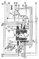
- FIG. 5is an electrical circuit diagram in schematic form of the transceiver circuitry, according to the preferred embodiment of the present invention.
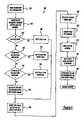
- FIG. 6is a flow diagram of the antenna tuning and power level adjustment at train time algorithm, according to the preferred embodiment of the present invention.
- FIG. 7is a flow diagram for the coarse tuning algorithm, according to the preferred embodiment of the present invention.
- FIG. 8is a flow diagram for the fine antenna tuning algorithm, according to the preferred embodiment of the present invention.
- FIG. 9is a flow diagram for the transmit power level control algorithm, according to the preferred embodiment of the present invention.
- FIGS. 10-11are graphs illustrating the power feedback with reference to the antenna boost voltage of the electrical circuitry, according to the preferred embodiment of the present invention.
- FIGS. 1 and 2show a trainable transceiver 10 of the present invention.
- Trainable transceiver 10includes three pushbutton switches 12 , 14 , and 16 , a light emitting diode (LED) 18 , and an electrical circuit board and associated circuits that may be mounted in a housing 20 .
- the switches 12 , 14 , and 16may each be associated with a separate garage door or other device to be controlled.
- the trainable transceiver housing 20is preferably of appropriate dimensions for mounting within a vehicle accessory such as an overhead console 22 as shown in FIG. 1 .
- the trainable transceiver 10includes electrical conductors coupled to the vehicle's electrical system for receiving power from the vehicle's battery.
- the overhead console 22includes other accessories such as map reading lamps 24 controlled by switches 26 . It may also include an electronic compass and display (not shown).
- the trainable transceiver 10may alternatively be permanently incorporated in a vehicle accessory such as a visor 28 ( FIG. 3 ) or a rearview mirror assembly 30 ( FIG. 4 ). Although the trainable transceiver 10 has been shown as incorporated in a visor and mirror assembly and removably located in an overhead console compartment, the trainable transceiver 10 could be permanently or removably located in the vehicle's instrument panel or any other suitable location within the vehicle's interior.
- FIG. 5shows the electrical circuitry of the trainable transceiver 10 in schematic form.
- the electrical circuit schematicmay be separated into seven primary components: power circuitry 32 ; user interface circuitry 34 ; a controller/microprocessor 36 and its associated circuitry which is used to execute the training, coarse tuning, fine tuning, and power level control software routines to be described later; a transceiver applications specific integrated circuit (ASIC) 38 and its associated circuitry; a voltage controlled oscillator (VCO) 40 ; antenna tuning circuitry 42 ; a plurality of antennas 44 ; and power level sense or detector circuitry 46 .
- ASICapplication specific integrated circuit
- VCOvoltage controlled oscillator
- the power supply circuitry 32is conventionally coupled to the vehicle's battery (not shown) through a connector and is coupled to the various components of the present invention and is used for supplying the necessary operating power to the trainable transceiver 10 .
- the user interface circuitry 34includes the switches 12 , 14 , and 16 that are electrically coupled to the data input terminals 48 of the microprocessor 36 through switch interface circuitry 50 , including filtering capacitors and sinking transistors.
- the switches 12 , 14 , and 16 as programmed by the usermay each correspond to a different device to be controlled such as different garage doors, electrically operated access gates, house lighting controls or the like, each of which may have their own unique operating RF frequency modulation scheme, and/or security code.
- the switches 12 , 14 , and 16correspond to different radio frequency channels that are generated by the trainable transceiver 10 .
- the transceiver 10will then transmit an RF signal having the identified characteristics of the RF activation signal.
- Each RF channelmay be trained to a different RF signal such that a plurality of devices in addition to a garage door opener may be activated by depressing one of the corresponding switches 12 , 14 , and 16 .
- Such other devicesmay include additional garage door openers, a building's interior or exterior lights, a home security system, or any other device capable of receiving an RF control signal.
- the microprocessor 36is further connected to the LED 18 by an output terminal which is illuminated when one of the switches 12 , 14 , and 16 is closed.
- the microprocessor 36is programmed to provide signals to the LED 18 .
- the LED 18will be controlled by the microprocessor 36 to slowly flash when the circuit enters a training mode for one of the RF channels associated with the switches 12 , 14 , and 16 .
- the LED 18will rapidly flash when a channel is successfully trained, and will slowly flash with a distinctive double blink to prompt the operator to reactuate the transceiver 10 .
- the LED 18may be a multi-color LED that changes color to indicate when a channel is successfully trained or to prompt the operator to reactuate the remote transmitter. Once trainable transceiver 10 is trained, the LED 18 lights continuously when one of the switches 12 , 14 , and 16 is depressed to indicate to the user that the transceiver 10 is transmitting a signal.
- the plurality of antennas 44includes a receiving antenna 52 and a transmission antenna 54 .
- the receiving antenna 52which receives a signal from a remote original transmitter (not shown) is coupled to a mixer 55 and a filter 56 , which process the received signal.
- the processed signalis applied to a series of cascaded differential IF amplifiers 57 coupled to a summing amplifier 58 to evaluate the transmission strength of the signal from the original transmitter.
- the output of the summing amplifier 58is applied to a comparator 59 whose reference voltage is provided by the AGC output 92 of the microprocessor 36 via an D/A converter 94 (the AGC output 92 doubles as the reference voltage for the comparator 59 and the control signal to the AGC amplifier 108 , as discussed below).
- the comparator 59will output a logical one signal. This logical one signal indicates to the microprocessor 36 that the power level of the original transmitter is acceptable to attempt to train the transceiver 10 .
- the transmission antenna 54is preferably a dynamically tunable loop antenna coupled indirectly via a choke 62 to a reference voltage level and coupled to varactor diodes 64 a and 64 b .
- the varactor diodes 64change the impedance characteristics of the transmission antenna 54 in response to a control voltage applied to the cathode of the varactor diodes 64 .
- the control voltageis determined by the microprocessor 36 which provides a pulse width modulated (PWM) signal from PWM output 66 to the antenna tuning circuitry 42 which converts the PWM signal to a control voltage.
- PWMpulse width modulated
- the transmission antenna 54may be dynamically tuned to maximize the efficiency at which it radiates a transmitted electromagnetic RF signal.
- the transmission antenna 54when the transmission antenna 54 is dynamically tuned to a resonance frequency corresponding to the carrier frequency of the transmitted signal, the transmission antenna 54 can remove unwanted harmonics from the signal.
- the transceiver ASIC 38 and the VCO 40Coupled to the transmission antenna 54 for transmitting a learned RF control signal is the transceiver ASIC 38 and the VCO 40 .
- the VCOhas a control input terminal 68 coupled to an output terminal 70 of the microprocessor 36 for controlling the frequency output of the VCO 40 .
- the VCO 40also includes an oscillator block 72 which outputs a sinusoidal signal and an LC resonator 74 .
- the LC resonator 74includes coupling capacitors 76 a and 76 b , inductors 78 a and 78 b , and varactor diodes 80 a and 80 b .
- the coupling capacitor 76 ahas one terminal connected to the oscillator 72 and the other terminal coupled to the inductor 78 a and the anode of the varactor diode 80 a .
- the coupling capacitor 76 bhas one terminal connected to the oscillator 72 and the other terminal coupled to both the inductor 78 b and the anode of the varactor diode 80 b .
- the inductors 78 and varactor diodes 80form a resonating LC circuit having a variable resonant frequency that is changed by varying the voltage to the cathodes of the varactor diodes 80 .
- This voltageis varied through the control input terminal 68 and a resistor 82 from the output terminal 70 of the microprocessor 36 .
- the microprocessor 36controls the voltage applied to control input terminal 68 .
- a feedback loopmay be incorporated into the control of the VCO 40 where the oscillation frequency is monitored by the microprocessor 36 which adjusts the voltage at the control input terminal 68 to generate the desired oscillation frequency (frequency synthesizer control).
- the feedbackis provided by a prescaler 86 coupled to an input 88 on the microprocessor 36 which measures the frequency of the VCO 40 output signal.
- the power level sense or detector circuitry 46 of the transceiver 10provides frequency and amplitude tuning feedback for the transmission antenna 54 .
- the detector 46comprises a Schottky diode 96 and bias components, including a capacitor 98 , functioning as a high pass filter or D.C. block, a resistor 100 tied to a voltage source (VCC), a resistor 102 , a resistor 104 , and a capacitor 106 , functioning as a low pass filter.
- This detector circuitry 46provides a DC voltage proportional to the RF voltage or power level on the transmission antenna 54 .
- the microprocessor 36is programmed with algorithms described below which tune the transmission antenna 54 via the varactor diodes 80 exactly to the peak resonance. It will be appreciated that the detector circuitry 46 may also be used to secure phase shift of the detected signal.
- Two methods of tuning the transmission antenna 54are use: (1) coarse tuning and (2) fine or “on the fly” tuning. Both types of tuning are performed each time one of the switches 12 , 14 , and 16 is actuated. Coarse tuning is performed prior to any modulation by sweeping the varactor diodes 64 across resonance. While sweeping the transmission antenna 54 varactor diode 64 voltages, the detector circuitry 46 output DC voltage is monitored. When the detector circuitry 46 output reaches a peak, the microprocessor 36 instantaneously measures and records the transmission antenna 54 tuning voltage. Then, through software, the transmission antenna 54 tune point is ascertained. Once coarse tuning is complete the transceiver 10 will begin to transmit. As the transceiver 10 begins modulating, the fine tuning algorithm will operate similar to the coarse tuning algorithm. The fine tuning algorithm will step the varactor diodes 64 , and ascertain the correct tuning voltage. Limits are in place to allow only a small amount of adjustment in the fine tuning mode.
- a further important factor to control in the transceiver 10 of the present inventionis the output power level control.
- the VCO 40provides the signal input to an automatic gain control (AGC) amplifier 108 coupled to an output amplifier 110 (both located in the transceiver ASIC 38 ) which provide the excitation for the transmission antenna 54 and thus the power level of the transmitted signal.
- the AGC amplifier's 108 gainis controlled by an analog voltage supplied by the microprocessor 36 from output 92 via a pulse width modulated digital to analog converter 94 .
- FCC regulationsallow different power levels base upon the duty cycle of a transmitted signal, it is advantageous for the trainable transceiver to be capable of dynamically adjusting the gain of the transmitted signal.
- the output level of the transceiver 10is linked to the on-time of the original transmitter. The shorter the, on-time of the original transmitter, the more output power allowed by the FCC. By providing the AGC amplifier 108 , the transceiver 10 can transmit at the maximum allowable power for each frequency and duty factor.
- the detector circuitry 46 voltagemay be incorporated as transmission power feedback to significantly reduce transmission power process errors. As described above with reference to the tuning of the transmission antenna 54 , the detector circuitry 46 outputs a DC voltage that is directly proportional to the RF voltage or power level on the transmission antenna 54 . The RF voltage on the transmission antenna 54 is directly proportional to the radiated field strength of the transmission antenna. Accordingly, algorithms are incorporated into the transceiver 10 to vary the output of the AGC amplifier 108 and therefore the output amplifier 110 and the radiated field strength of the transmission antenna 54 in response to the detector circuitry 46 DC voltage feedback. This feedback may be used to control both the tuning of the transmission antenna 64 resonance and the transmission power of the transmission antenna 64 .
- the duty cycleis measured at train time, this is used to calculate the needed transmission power level.
- This valveis stored in nonvolatile memory (NVM) in the microprocessor 36 . Radiated field measurements were previously taken (during the product development of the transceiver 10 ) to characterize the exact relationship between detector 46 voltage and field strength. This information is loaded into the power level control algorithm and is used to calculate detector 46 target voltages based on the duty cycle of the desired signal.
- NVMnonvolatile memory
- a target detector 46 voltageis recovered from the NVM and loaded into the power level control routine. Once the antenna is tuned, the power level control routine adjusts the AGC control voltage until the detector 46 voltage is equal to the target voltage. Ongoing monitoring of the detector 46 voltage ensures that the field strength remains constant. Thus, since the detector 46 output voltage is accurate, the output field strength is always kept very close to optimum output field strength over process, temperature and various load.
- the AGC 108will increase the voltage it applies to the output amplifier.
- the AGC 108will be controlled by algorithms in the microprocessor 36 via the digital to analog converter 94 to increase the transmission antenna 54 output.
- the algorithmswill calculate, according to FCC regulations, the maximum output power allowed and then monitor and control the output power on the transmission antenna 54 with feedback provided by the detector circuitry 46 .
- the transceiver 10 of the present inventionmay compensate.
- the detector circuitry 46will provide feedback which is used by the microprocessor 36 and its associated algorithms to increase or decrease the output power of the transmission antenna 54 to the setpoint needed.
- the detector circuitry 46in combination with the rest of the transceiver 10 circuitry, provides an accurate measure of the transmission power of the transmission antenna 54 .
- the transceiver 10may take advantage of FCC regulations to increase output power for original remote transmitters which have low duty cycles and compensate for other factors which might adversely affect the transmission power of the transceiver 10 .
- the algorithms used in the present inventioninclude: a training algorithm which incorporates antenna tuning and power level adjustment; a coarse antenna tuning routine which roughly tunes the transmission antenna 54 ; a fine tuning or “on the fly” tuning routine which improves upon the transmission antenna 54 tuning of the coarse tuning routine; and a transmit power level control routine which varies the power output of the transmission antenna 54 .
- the training routine 150teaches the transceiver 10 of the present invention the radio frequency, modulation scheme, and data code for an original portable remote transmitter associated with an existing receiving unit.
- the operatorinitiates the training sequence at the user interface and, at the same time, the operator initiates the transmit function of the existing portable transmitter.
- the transceiver 10will detect the frequency of the transmission on receiving antenna 52 .
- the FCC power limit for continuous wave (CW) modewill be retrieved from the NVM. As discussed previously, the FCC limits transmission power with respect to duty cycle.
- CWcontinuous wave
- the routine 150will determine if the data code is for a specific existing portable transmitter and set the duty cycle.
- the routine 150will advance to block 126 and the duty cycle will be set at 50%. If the transmitted information is not from a Genie transmitter, the routine 150 will advance to block 128 which will determine if the transmitted data is rolling code with blank alternative code word (BACW).
- BACWblank alternative code word
- rolling code routineschange the data being transmitted to a receiver, thus varying the duty cycle. If the transmitted data is rolling code with BACW, the routine 150 will advance to block 130 which will set the duty cycle to approximately 30%.
- the longest duty cycle for rolling code with BACWhas been empirically determined to be approximately 30%, thus approximately 30% is the worst case. If the transmitted information is not rolling code with BACW, block 132 will determine if the transmitted data is rolling code without BACW. If the transmitted data is rolling code without BACW, the routine will advance to block 134 which will set the duty cycle to 53%. The longest duty cycle for rolling code without BACW has been empirically determined to be 53%, thus 53% is the worst case. If the transmitted information is not rolling code without BACW the routine 150 will advance to block 136 . Block 136 will then calculate the duty cycle based on the bit pattern trained.
- the routine 150will advance to block 138 where the duty cycle is inverted and multiplied by the previously retrieved FCC power limit for the frequency of transmission. For example, a 50% duty cycle will enable the transceiver to transmit at twice the power level for a continuous wave transmission having the same frequency. After this power level has been determined, the program advances to block 140 , where the power level is stored in NVM.
- the routine 150will then advance to a coarse antenna tuning block/routine 142 and a fine antenna tuning block/routine 144 which will be described in detail below.
- the control parameters for the antenna tuning and power transmission calculationswill be stored in NVM at block 148 for retransmission.
- the coarse antenna tuning routine 142will now be described.
- the coarse antenna tuning routinewill roughly tune the antenna 54 before any transmission of data takes place.
- the coarse antenna tuningis performed each time one of the switches 12 , 14 , and 16 of the user interface circuitry 36 is actuated to successfully train the transceiver 10 or transmit data to a remote receiver.
- the VCO 40is set to generate the frequency which was learned from an existing portable transmitter.
- the VCO 40will stabilize the generated frequency using the frequency synthesizer control previously described.
- the transceiver 10will further be put into transmit mode and the peak tune level will be initialized to zero.
- the routine 142will then advance to block 154 where a starting transmission power level is read from NVM and is used to set the AGC 108 .
- the transmission power levelis held constant through the coarse tuning routine so that the detector circuit 46 output is only affected by the transmission antenna 54 tuning.
- Block 154also sets the frequency tuning of the transmission antenna 54 to a default value such as 310 MHz in case of a hardware fault. This default level will ensure that the transmission antenna 54 is at least roughly tuned in the event of such a hardware fault.
- the routine 142will then advance to block 156 where the upper and lower tuning limits for the PWM output 66 /antenna tuning circuitry 42 are set. To reiterate, the PWM output 66 is the control output of the microprocessor 36 for tuning the transmission antenna 54 .
- the antenna tuning circuitry 42converts the PWM output to a DC voltage which is applied to the varactors 64 .
- the voltage output from the antenna tuning circuitry 42is ramped up via the change in the output of the PWM output 66 which is controlled by the microprocessor 36 .
- the output of the detector circuit 46is compared to the noise level. If the output of the detector circuit 46 is greater than the noise floor, then the interrupts are disabled and sampling speed is increased in block 164 . If the opposite is true the routine 142 will advance to block 162 where the frequency will be checked and then corrected, an led will flash if needed, and the interrupts will run. Both block 162 and 164 will advance to block 166 where a sample of the detector circuit 46 output will be taken. As previously mentioned, the detector circuit 46 voltage output is directly related to the RF voltage or power level transmitted by the transmission antenna 54 .
- Block 168determines if the sampled detector circuit 46 output is greater than the peak power sample.
- the peak power sampleis the detector circuit 46 output sample of greatest magnitude which has been measured during this coarse tuning routine 142 . If the sampled detector circuit 46 output is greater than the peak power sample, this latest sampled detector circuit 46 output now becomes the peak power sample and is saved, as seen in blocks 170 and 172 . If the sampled detector circuit 46 output is not greater than the peak power sample, the routine will return to block 158 and continue to ramp the antenna tuning circuitry 42 output voltage. The routine 142 will also continue to test if the latest detector circuit 46 output is greater than the peak power sample until the antenna voltage is finished ramping, as seen in block 174 .
- Block 174verifies that the ramping of the antenna circuitry 42 output voltage is finished and the routine 142 then advances to block 176 which determines if the ramping of the antenna circuitry 42 output voltage has been ramped up and down. If the antenna circuitry 42 voltage has not been ramped in both directions, then the ramp direction will be changed at block 178 and the routine 142 will return to block 158 to execute the ramping blocks again.
- the PWM output 66 /antenna circuitry 42 output voltagewill be examined to see if its value is too low. As described above, the PWM output 66 signal is converted to a DC voltage value by the antenna circuitry 42 to bias the varactor diodes 64 . A low antenna circuitry 42 output voltage may occur as a result of circuit failure. If the value is to low, a default PWM output 66 antenna circuitry 42 output voltage will be loaded at block 182 . If the value is not to low, the routine 142 will advance to block 184 where the peak tuning point for the antenna 54 will be calculated.
- Block 186the detector circuit 46 output voltage is examined to see if its value is too low.
- Block 186double checks the detector circuit 46 feedback and determines if there is a detector circuit 46 failure or total tuning failure. If the value is too low, a default PWM output 66 /antenna circuitry 42 output voltage will be loaded at block 188 .
- the PWM output 66 /antenna circuitry output 42is set and output to the varactor diodes 64 and the transmission power level or gain on the AGC 108 is set.
- the routine 142then waits for the AGC 108 to ramp up and the transmission antenna 54 tuning voltages to finalize. Then transmission antenna 54 is then coarse tuned.
- the fine tuning routine 144is executed while the transceiver 10 is transmitting.
- the fine tuning routine 144improves upon the tuning of the coarse tuning routine 142 to better tune the transmission antenna 54 for a particular transmission frequency.
- the fine tuning routine 144uses smaller increments for the PWM output 66 and therefore has better resolution which leads to improved tuning for the transmission antenna 46 .
- the fine tuning routine 144sets the antenna tuning point or PWM output 66 to a certain number of counts below the previously calculated coarse tuning counts which correspond to the peak power sample (generated by the detector circuit 46 output). A count is defined as the duty cycle factor for the PWM output 66 .
- the tuningwill stop when the routine reaches a certain number of counts above the coarse peak.
- datawill be transmitted in the background on the transmission antenna 54 .
- the detector circuit 46 output voltagewill then be sampled at block 204 .
- the following blocks 206 and 208are similar to blocks 168 and 170 in the coarse tuning routine 142 .
- the sampled detector circuit 46 output voltagewill be compared to a peak sample. If the sampled detector circuit 46 output is greater than the peak power sample, this latest sampled detector circuit 46 output is saved as the latest peak power sample.
- four sampleswill be taken.
- the routine 144will check if it has reached the upper bound of counts over the coarse value. If the routine 144 has not reached the upper bound, then the routine 144 will return to block 202 and repeat the sampling blocks. If the upper bound has been reached, then the routine 144 will continue to block 216 and set the antenna tuning point or PWM output 66 to the peak value, finishing the fine tuning routine 144 .
- FIGS. 10-11illustrate the PWM output 66 /antenna circuitry 42 output voltage and detector circuit 46 output voltage vs. time.
- the antenna boost voltage or antenna circuitry 42 output voltagevaries the power output of the transmission antenna 54 .
- the detector circuit 46 output voltageis directly related to the power output of the transmission antenna 54 .
- the sweeping action of the antenna boost voltagevaries the detector circuitry 46 output.
- the peak resonance points of the transmission antenna 54may be determined by the peaks in the detector circuitry 46 output.
- the coarse tuning 142 and fine tuning 144 routinesare executed once at the beginning of each action by the vehicle operator.
- the following transmit power level control routine 218is continuously executed upon the completion of the coarse 142 and fine 144 tuning routines.
- the transmit power level control routine 218controls the output power of the transmission antenna 54 with reference to the duty cycle calculation and environmental variables.
- the output for the PWM output 66 and its corresponding target peak power level for the specific remote transmitter model format being usedis loaded from NVM and the peak power is set to zero. This stored target peak power level gives the power level control routine 218 a starting point in the feedback loop to improve the response of the feedback loop.
- datais transmitted on transmission antenna 54 .
- the detector circuit 46 outputis sampled.
- the current sampled detector circuit 46 outputis compared to a stored peak power value. If the current sampled detector circuit 46 output is greater than the peak power value, then the current sampled detector circuit 46 output is stored as the new peak power value and the PWM output 92 counts is also stored.
- the PWM output 92is the microprocessor control output for changing the power of the transmission for transmission antenna 54 .
- the PWM output 92is coupled to the D/A converter 94 which controls the gain on the AGC 108 .
- routine 218continues to block 230 to determine if sixteen samples have been taken. If sixteen samples have not been taken, the routine 218 will return to block 222 and continue to take samples. If sixteen samples have been taken, the routine will continue to blocks 232 - 238 where the PWM output 92 counts will be adjusted with reference to the detector circuit 46 output sample. At block 232 , the routine 218 will determine if the PWM output 92 is greater than eight counts from the previously loaded corresponding target power level. If the sample is greater than eight counts from the target power level, than the PWM output 92 will be adjusted by two counts.
- block 236will determine if the PWM output 92 is greater than four counts from the target power level. If the sample is greater than four counts from the target power level, then the PWM output 92 , will be adjusted by one count. If the sample is not greater than four counts from the target power level, then the PWM output 92 which controls the AGC 108 will be set. The AGC 108 , as previously discussed, controls the RF voltage or transmission power of the transmission antenna 54 . Finally, at block 242 , a delay is incorporated to allow the AGC 108 to ramp up and reach its final value. The transmit power level routine will then execute continuously while an operator is actuating the user interface 34 of the transceiver.
Landscapes
- Physics & Mathematics (AREA)
- General Physics & Mathematics (AREA)
- Engineering & Computer Science (AREA)
- Computer Networks & Wireless Communication (AREA)
- Transmitters (AREA)
Abstract
Description
Claims (20)
Priority Applications (1)
| Application Number | Priority Date | Filing Date | Title |
|---|---|---|---|
| US11/311,007US7469129B2 (en) | 1999-06-07 | 2005-12-19 | Transceiver with closed loop control of antenna tuning and power level |
Applications Claiming Priority (4)
| Application Number | Priority Date | Filing Date | Title |
|---|---|---|---|
| US13786099P | 1999-06-07 | 1999-06-07 | |
| US10/009,236US6978126B1 (en) | 1999-06-07 | 2000-06-07 | Transceiver with closed loop control of antenna tuning and power level |
| PCT/US2000/040159WO2000075905A1 (en) | 1999-06-07 | 2000-06-07 | Transceiver with closed loop control of antenna tuning and power level |
| US11/311,007US7469129B2 (en) | 1999-06-07 | 2005-12-19 | Transceiver with closed loop control of antenna tuning and power level |
Related Parent Applications (3)
| Application Number | Title | Priority Date | Filing Date |
|---|---|---|---|
| US10/009,236ContinuationUS6978126B1 (en) | 1999-06-07 | 2000-06-07 | Transceiver with closed loop control of antenna tuning and power level |
| US10009236Continuation | 2000-06-07 | ||
| PCT/US2000/040159ContinuationWO2000075905A1 (en) | 1999-06-07 | 2000-06-07 | Transceiver with closed loop control of antenna tuning and power level |
Publications (2)
| Publication Number | Publication Date |
|---|---|
| US20060234670A1 US20060234670A1 (en) | 2006-10-19 |
| US7469129B2true US7469129B2 (en) | 2008-12-23 |
Family
ID=35465667
Family Applications (2)
| Application Number | Title | Priority Date | Filing Date |
|---|---|---|---|
| US10/009,236Expired - LifetimeUS6978126B1 (en) | 1999-06-07 | 2000-06-07 | Transceiver with closed loop control of antenna tuning and power level |
| US11/311,007Expired - LifetimeUS7469129B2 (en) | 1999-06-07 | 2005-12-19 | Transceiver with closed loop control of antenna tuning and power level |
Family Applications Before (1)
| Application Number | Title | Priority Date | Filing Date |
|---|---|---|---|
| US10/009,236Expired - LifetimeUS6978126B1 (en) | 1999-06-07 | 2000-06-07 | Transceiver with closed loop control of antenna tuning and power level |
Country Status (1)
| Country | Link |
|---|---|
| US (2) | US6978126B1 (en) |
Cited By (42)
| Publication number | Priority date | Publication date | Assignee | Title |
|---|---|---|---|---|
| US20100124890A1 (en)* | 2008-10-27 | 2010-05-20 | Marco Schwarzmueller | Circuit for a loop antenna and method for tuning |
| US20110298419A1 (en)* | 2010-06-03 | 2011-12-08 | Tsai Ming-Chiu | Method for identification of a light inductive charger |
| US20130181787A1 (en)* | 2007-04-23 | 2013-07-18 | Research In Motion Limited | Adaptive impedance matching |
| US8693963B2 (en) | 2000-07-20 | 2014-04-08 | Blackberry Limited | Tunable microwave devices with auto-adjusting matching circuit |
| US8712340B2 (en) | 2011-02-18 | 2014-04-29 | Blackberry Limited | Method and apparatus for radio antenna frequency tuning |
| US8781417B2 (en) | 2007-05-07 | 2014-07-15 | Blackberry Limited | Hybrid techniques for antenna retuning utilizing transmit and receive power information |
| US8787845B2 (en) | 2009-08-25 | 2014-07-22 | Blackberry Limited | Method and apparatus for calibrating a communication device |
| US8798555B2 (en) | 2007-11-14 | 2014-08-05 | Blackberry Limited | Tuning matching circuits for transmitter and receiver bands as a function of the transmitter metrics |
| US8803631B2 (en) | 2010-03-22 | 2014-08-12 | Blackberry Limited | Method and apparatus for adapting a variable impedance network |
| US8860526B2 (en) | 2010-04-20 | 2014-10-14 | Blackberry Limited | Method and apparatus for managing interference in a communication device |
| US8942657B2 (en) | 2006-01-14 | 2015-01-27 | Blackberry Limited | Adaptive matching network |
| US8948889B2 (en) | 2012-06-01 | 2015-02-03 | Blackberry Limited | Methods and apparatus for tuning circuit components of a communication device |
| US8957742B2 (en) | 2008-09-24 | 2015-02-17 | Blackberry Limited | Methods for tuning an adaptive impedance matching network with a look-up table |
| US9026062B2 (en) | 2009-10-10 | 2015-05-05 | Blackberry Limited | Method and apparatus for managing operations of a communication device |
| US9130543B2 (en) | 2006-11-08 | 2015-09-08 | Blackberry Limited | Method and apparatus for adaptive impedance matching |
| US9246223B2 (en) | 2012-07-17 | 2016-01-26 | Blackberry Limited | Antenna tuning for multiband operation |
| US9263806B2 (en) | 2010-11-08 | 2016-02-16 | Blackberry Limited | Method and apparatus for tuning antennas in a communication device |
| US9350405B2 (en) | 2012-07-19 | 2016-05-24 | Blackberry Limited | Method and apparatus for antenna tuning and power consumption management in a communication device |
| US9362891B2 (en) | 2012-07-26 | 2016-06-07 | Blackberry Limited | Methods and apparatus for tuning a communication device |
| US9374113B2 (en) | 2012-12-21 | 2016-06-21 | Blackberry Limited | Method and apparatus for adjusting the timing of radio antenna tuning |
| US9413066B2 (en) | 2012-07-19 | 2016-08-09 | Blackberry Limited | Method and apparatus for beam forming and antenna tuning in a communication device |
| US9419581B2 (en) | 2006-11-08 | 2016-08-16 | Blackberry Limited | Adaptive impedance matching apparatus, system and method with improved dynamic range |
| US9473216B2 (en) | 2011-02-25 | 2016-10-18 | Blackberry Limited | Method and apparatus for tuning a communication device |
| US9576408B2 (en) | 2014-07-30 | 2017-02-21 | Gentex Corporation | Battery powered trainable remote garage door opener module |
| US9627908B2 (en) | 2012-03-13 | 2017-04-18 | Maxwell Technologies, Inc. | Ultracapacitor and battery combination with electronic management system |
| US9716311B2 (en) | 2011-05-16 | 2017-07-25 | Blackberry Limited | Method and apparatus for tuning a communication device |
| US9715772B2 (en) | 2013-11-15 | 2017-07-25 | Gentex Corporation | Internet-connected garage door control system |
| US9769826B2 (en) | 2011-08-05 | 2017-09-19 | Blackberry Limited | Method and apparatus for band tuning in a communication device |
| US9853363B2 (en) | 2012-07-06 | 2017-12-26 | Blackberry Limited | Methods and apparatus to control mutual coupling between antennas |
| US10003393B2 (en) | 2014-12-16 | 2018-06-19 | Blackberry Limited | Method and apparatus for antenna selection |
| US10163574B2 (en) | 2005-11-14 | 2018-12-25 | Blackberry Limited | Thin films capacitors |
| US10404295B2 (en) | 2012-12-21 | 2019-09-03 | Blackberry Limited | Method and apparatus for adjusting the timing of radio antenna tuning |
| US20200410794A1 (en)* | 2019-06-25 | 2020-12-31 | Microchip Technology Incorporated | Configurable access controller, and related systems, methods, and devices |
| US10997810B2 (en) | 2019-05-16 | 2021-05-04 | The Chamberlain Group, Inc. | In-vehicle transmitter training |
| US11024192B2 (en) | 2016-06-07 | 2021-06-01 | Gentex Corporation | Vehicle trainable transceiver for allowing cloud-based transfer of data between vehicles |
| US11074773B1 (en) | 2018-06-27 | 2021-07-27 | The Chamberlain Group, Inc. | Network-based control of movable barrier operators for autonomous vehicles |
| US11220856B2 (en) | 2019-04-03 | 2022-01-11 | The Chamberlain Group Llc | Movable barrier operator enhancement device and method |
| US11411594B2 (en) | 2019-04-30 | 2022-08-09 | Gentex Corporation | Vehicle trainable transceiver having a programmable oscillator |
| US11423717B2 (en) | 2018-08-01 | 2022-08-23 | The Chamberlain Group Llc | Movable barrier operator and transmitter pairing over a network |
| US11470063B2 (en) | 2018-08-17 | 2022-10-11 | Gentex Corporation | Vehicle configurable transmitter for allowing cloud-based transfer of data between vehicles |
| US20220394534A1 (en)* | 2019-11-20 | 2022-12-08 | Nokia Technologies Oy | Apparatus for receiving a measurement |
| US11778464B2 (en) | 2017-12-21 | 2023-10-03 | The Chamberlain Group Llc | Security system for a moveable barrier operator |
Families Citing this family (38)
| Publication number | Priority date | Publication date | Assignee | Title |
|---|---|---|---|---|
| US6253068B1 (en)* | 1997-05-09 | 2001-06-26 | Micrel, Incorporated | Fully integrated all-CMOS AM transmitter with automatic antenna tuning |
| US6658239B1 (en)* | 1997-05-09 | 2003-12-02 | Micrel Incorporated | Fully integrated ALL-CMOS AM transmitter with automatic antenna tuning |
| US7268700B1 (en) | 1998-01-27 | 2007-09-11 | Hoffberg Steven M | Mobile communication device |
| US9818136B1 (en) | 2003-02-05 | 2017-11-14 | Steven M. Hoffberg | System and method for determining contingent relevance |
| US8330569B2 (en)* | 2003-05-28 | 2012-12-11 | Johnson Controls Technology Company | System and method for receiving data for training a trainable transmitter |
| US7183941B2 (en) | 2003-07-30 | 2007-02-27 | Lear Corporation | Bus-based appliance remote control |
| US7269416B2 (en) | 2003-07-30 | 2007-09-11 | Lear Corporation | Universal vehicle based garage door opener control system and method |
| US7183940B2 (en) | 2003-07-30 | 2007-02-27 | Lear Corporation | Radio relay appliance activation |
| US7161466B2 (en) | 2003-07-30 | 2007-01-09 | Lear Corporation | Remote control automatic appliance activation |
| US7039397B2 (en)* | 2003-07-30 | 2006-05-02 | Lear Corporation | User-assisted programmable appliance control |
| US7068181B2 (en) | 2003-07-30 | 2006-06-27 | Lear Corporation | Programmable appliance remote control |
| US7046119B2 (en)* | 2004-05-19 | 2006-05-16 | Lear Corporation | Vehicle independent passive entry system |
| US7590589B2 (en) | 2004-09-10 | 2009-09-15 | Hoffberg Steven M | Game theoretic prioritization scheme for mobile ad hoc networks permitting hierarchal deference |
| JP2006174154A (en)* | 2004-12-16 | 2006-06-29 | Omron Corp | Transmitter |
| US7376401B2 (en)* | 2005-04-12 | 2008-05-20 | Wayne-Dalton Corp. | Frequency matching and optimization system for an RF receiver |
| US8058970B2 (en)* | 2005-08-24 | 2011-11-15 | Homerun Holdings Corporation | System and methods for automatically moving access barriers initiated by mobile transmitter devices |
| US7327107B2 (en)* | 2005-08-24 | 2008-02-05 | Wayne-Dalton Corp. | System and methods for automatically moving access barriers initiated by mobile transmitter devices |
| US8874477B2 (en) | 2005-10-04 | 2014-10-28 | Steven Mark Hoffberg | Multifactorial optimization system and method |
| US20070216516A1 (en)* | 2006-03-14 | 2007-09-20 | Lear Corporation | Security system and method for in-vehicle remote transmitter |
| US7589613B2 (en) | 2006-04-03 | 2009-09-15 | Lear Corporation | Trinary to trinary rolling code generation method and system |
| US7933324B2 (en)* | 2006-05-31 | 2011-04-26 | Lear Corporation | Power regulator |
| US7684751B2 (en)* | 2006-09-26 | 2010-03-23 | Intel Corporation | Radio frequency identification apparatus, system and method adapted for self-jammer cancellation |
| PL2092275T3 (en)* | 2006-12-20 | 2013-03-29 | Johnson Controls Tech Co | System and method for providing route calculation and information to a vehicle |
| EP2091784B1 (en) | 2006-12-20 | 2012-02-01 | Johnson Controls Technology Company | Remote display reproduction system and method |
| WO2008091727A1 (en) | 2007-01-23 | 2008-07-31 | Johnson Controls Technology Company | Mobile device gateway systems and methods |
| US7409245B1 (en)* | 2007-01-30 | 2008-08-05 | Cardiac Pacemakers, Inc. | Variable antenna matching network for an implantable antenna |
| US7458627B2 (en)* | 2007-03-05 | 2008-12-02 | Lear Corporation | Visor assembly incorporating an electronic control module |
| US7843822B1 (en)* | 2007-05-24 | 2010-11-30 | Rockwell Collins, Inc. | Cognitive adaptive network management areas |
| WO2009073806A2 (en) | 2007-12-05 | 2009-06-11 | Johnson Controls Technology Company | Vehicle user interface systems and methods |
| US9324230B2 (en) | 2008-12-04 | 2016-04-26 | Gentex Corporation | System and method for configuring a wireless control system of a vehicle using induction field communication |
| US8706053B2 (en)* | 2009-11-19 | 2014-04-22 | Sony Corporation | Communications circuitry for an electronic device |
| US8212218B2 (en)* | 2009-11-30 | 2012-07-03 | International Business Machines Corporation | Dosimeter powered by passive RF absorption |
| IT1399761B1 (en)* | 2010-05-03 | 2013-05-03 | Faac Spa | METHOD AND DEVICE FOR THE OPTIMIZED TRANSMISSION OF REMOTE CONTROL SIGNALS PARTICULARLY OF GATES, DOORS AND BARRIERS |
| US8917212B2 (en) | 2011-07-08 | 2014-12-23 | At&T Mobility Ii Llc | Antenna verification via transmitter |
| KR101912163B1 (en)* | 2012-02-27 | 2018-10-26 | 삼성전자주식회사 | Method of modulation and demodulation for nano communication,and receiver device using the method |
| US10312958B2 (en)* | 2013-03-05 | 2019-06-04 | Gentex Corporation | Remote receive antenna for vehicle communication system |
| US9711039B2 (en)* | 2015-03-10 | 2017-07-18 | Gentex Corporation | Increasing radio frequency power of activation messages by adding dead time |
| US10218403B2 (en)* | 2017-07-30 | 2019-02-26 | Dell Products, Lp | System and method for a modular dynamic wireless power control system in a convertible information handling system |
Citations (11)
| Publication number | Priority date | Publication date | Assignee | Title |
|---|---|---|---|---|
| US3959746A (en)* | 1973-10-17 | 1976-05-25 | International Telephone And Telegraph Corporation | Automatic antenna coupler tuning control circuit |
| US4343001A (en)* | 1980-10-24 | 1982-08-03 | Rockwell International Corporation | Digitally tuned electrically small antenna |
| US5225847A (en)* | 1989-01-18 | 1993-07-06 | Antenna Research Associates, Inc. | Automatic antenna tuning system |
| US5263183A (en)* | 1991-04-30 | 1993-11-16 | Seiko Corp. | Radio antenna tuning circuit |
| US5646701A (en)* | 1990-08-14 | 1997-07-08 | Prince Corporation | Trainable transmitter with transmit/receive switch |
| US5699054A (en)* | 1995-05-19 | 1997-12-16 | Prince Corporation | Trainable transceiver including a dynamically tunable antenna |
| US5699055A (en)* | 1995-05-19 | 1997-12-16 | Prince Corporation | Trainable transceiver and method for learning an activation signal that remotely actuates a device |
| US5793300A (en)* | 1993-03-15 | 1998-08-11 | Prince Corporation | Trainable RF receiver for remotely controlling household appliances |
| US5854593A (en)* | 1996-07-26 | 1998-12-29 | Prince Corporation | Fast scan trainable transmitter |
| US6021319A (en)* | 1992-09-24 | 2000-02-01 | Colorado Meadowlark Corporation | Remote control system |
| US6091343A (en)* | 1997-12-18 | 2000-07-18 | Prince Corporation | Trainable RF transmitter having expanded learning capabilities |
Family Cites Families (8)
| Publication number | Priority date | Publication date | Assignee | Title |
|---|---|---|---|---|
| US5479155A (en)* | 1988-12-05 | 1995-12-26 | Prince Corporation | Vehicle accessory trainable transmitter |
| US5442340A (en)* | 1988-12-05 | 1995-08-15 | Prince Corporation | Trainable RF transmitter including attenuation control |
| US5126686A (en)* | 1989-08-15 | 1992-06-30 | Astec International, Ltd. | RF amplifier system having multiple selectable power output levels |
| US5379453A (en)* | 1992-09-24 | 1995-01-03 | Colorado Meadowlark Corporation | Remote control system |
| US5564101A (en)* | 1993-07-09 | 1996-10-08 | Universal Devices | Method and apparatus for transmitter for universal garage door opener |
| US5645701A (en)* | 1996-03-08 | 1997-07-08 | Dufresne; Jean L. | Capping board with pultruded filling bars |
| US6072404A (en)* | 1997-04-29 | 2000-06-06 | Eaton Corporation | Universal garage door opener |
| US6658239B1 (en)* | 1997-05-09 | 2003-12-02 | Micrel Incorporated | Fully integrated ALL-CMOS AM transmitter with automatic antenna tuning |
- 2000
- 2000-06-07USUS10/009,236patent/US6978126B1/ennot_activeExpired - Lifetime
- 2005
- 2005-12-19USUS11/311,007patent/US7469129B2/ennot_activeExpired - Lifetime
Patent Citations (12)
| Publication number | Priority date | Publication date | Assignee | Title |
|---|---|---|---|---|
| US3959746A (en)* | 1973-10-17 | 1976-05-25 | International Telephone And Telegraph Corporation | Automatic antenna coupler tuning control circuit |
| US4343001A (en)* | 1980-10-24 | 1982-08-03 | Rockwell International Corporation | Digitally tuned electrically small antenna |
| US5225847A (en)* | 1989-01-18 | 1993-07-06 | Antenna Research Associates, Inc. | Automatic antenna tuning system |
| US5646701A (en)* | 1990-08-14 | 1997-07-08 | Prince Corporation | Trainable transmitter with transmit/receive switch |
| US5263183A (en)* | 1991-04-30 | 1993-11-16 | Seiko Corp. | Radio antenna tuning circuit |
| US6021319A (en)* | 1992-09-24 | 2000-02-01 | Colorado Meadowlark Corporation | Remote control system |
| US5793300A (en)* | 1993-03-15 | 1998-08-11 | Prince Corporation | Trainable RF receiver for remotely controlling household appliances |
| US5903226A (en)* | 1993-03-15 | 1999-05-11 | Prince Corporation | Trainable RF system for remotely controlling household appliances |
| US5699054A (en)* | 1995-05-19 | 1997-12-16 | Prince Corporation | Trainable transceiver including a dynamically tunable antenna |
| US5699055A (en)* | 1995-05-19 | 1997-12-16 | Prince Corporation | Trainable transceiver and method for learning an activation signal that remotely actuates a device |
| US5854593A (en)* | 1996-07-26 | 1998-12-29 | Prince Corporation | Fast scan trainable transmitter |
| US6091343A (en)* | 1997-12-18 | 2000-07-18 | Prince Corporation | Trainable RF transmitter having expanded learning capabilities |
Cited By (89)
| Publication number | Priority date | Publication date | Assignee | Title |
|---|---|---|---|---|
| US8896391B2 (en) | 2000-07-20 | 2014-11-25 | Blackberry Limited | Tunable microwave devices with auto-adjusting matching circuit |
| US9768752B2 (en) | 2000-07-20 | 2017-09-19 | Blackberry Limited | Tunable microwave devices with auto-adjusting matching circuit |
| US9948270B2 (en) | 2000-07-20 | 2018-04-17 | Blackberry Limited | Tunable microwave devices with auto-adjusting matching circuit |
| US8693963B2 (en) | 2000-07-20 | 2014-04-08 | Blackberry Limited | Tunable microwave devices with auto-adjusting matching circuit |
| US9431990B2 (en) | 2000-07-20 | 2016-08-30 | Blackberry Limited | Tunable microwave devices with auto-adjusting matching circuit |
| US10163574B2 (en) | 2005-11-14 | 2018-12-25 | Blackberry Limited | Thin films capacitors |
| US9853622B2 (en) | 2006-01-14 | 2017-12-26 | Blackberry Limited | Adaptive matching network |
| US10177731B2 (en) | 2006-01-14 | 2019-01-08 | Blackberry Limited | Adaptive matching network |
| US8942657B2 (en) | 2006-01-14 | 2015-01-27 | Blackberry Limited | Adaptive matching network |
| US9130543B2 (en) | 2006-11-08 | 2015-09-08 | Blackberry Limited | Method and apparatus for adaptive impedance matching |
| US9722577B2 (en) | 2006-11-08 | 2017-08-01 | Blackberry Limited | Method and apparatus for adaptive impedance matching |
| US10020828B2 (en) | 2006-11-08 | 2018-07-10 | Blackberry Limited | Adaptive impedance matching apparatus, system and method with improved dynamic range |
| US10050598B2 (en) | 2006-11-08 | 2018-08-14 | Blackberry Limited | Method and apparatus for adaptive impedance matching |
| US9419581B2 (en) | 2006-11-08 | 2016-08-16 | Blackberry Limited | Adaptive impedance matching apparatus, system and method with improved dynamic range |
| US9698748B2 (en)* | 2007-04-23 | 2017-07-04 | Blackberry Limited | Adaptive impedance matching |
| US20130181787A1 (en)* | 2007-04-23 | 2013-07-18 | Research In Motion Limited | Adaptive impedance matching |
| US8781417B2 (en) | 2007-05-07 | 2014-07-15 | Blackberry Limited | Hybrid techniques for antenna retuning utilizing transmit and receive power information |
| US9119152B2 (en) | 2007-05-07 | 2015-08-25 | Blackberry Limited | Hybrid techniques for antenna retuning utilizing transmit and receive power information |
| USRE47412E1 (en) | 2007-11-14 | 2019-05-28 | Blackberry Limited | Tuning matching circuits for transmitter and receiver bands as a function of the transmitter metrics |
| US8798555B2 (en) | 2007-11-14 | 2014-08-05 | Blackberry Limited | Tuning matching circuits for transmitter and receiver bands as a function of the transmitter metrics |
| USRE48435E1 (en) | 2007-11-14 | 2021-02-09 | Nxp Usa, Inc. | Tuning matching circuits for transmitter and receiver bands as a function of the transmitter metrics |
| US8957742B2 (en) | 2008-09-24 | 2015-02-17 | Blackberry Limited | Methods for tuning an adaptive impedance matching network with a look-up table |
| US9698758B2 (en) | 2008-09-24 | 2017-07-04 | Blackberry Limited | Methods for tuning an adaptive impedance matching network with a look-up table |
| US20100124890A1 (en)* | 2008-10-27 | 2010-05-20 | Marco Schwarzmueller | Circuit for a loop antenna and method for tuning |
| US8306489B2 (en)* | 2008-10-27 | 2012-11-06 | Atmel Corporation | Circuit for a loop antenna and method for tuning |
| US9020446B2 (en) | 2009-08-25 | 2015-04-28 | Blackberry Limited | Method and apparatus for calibrating a communication device |
| US8787845B2 (en) | 2009-08-25 | 2014-07-22 | Blackberry Limited | Method and apparatus for calibrating a communication device |
| US10659088B2 (en) | 2009-10-10 | 2020-05-19 | Nxp Usa, Inc. | Method and apparatus for managing operations of a communication device |
| US9026062B2 (en) | 2009-10-10 | 2015-05-05 | Blackberry Limited | Method and apparatus for managing operations of a communication device |
| US9608591B2 (en) | 2010-03-22 | 2017-03-28 | Blackberry Limited | Method and apparatus for adapting a variable impedance network |
| US10615769B2 (en) | 2010-03-22 | 2020-04-07 | Blackberry Limited | Method and apparatus for adapting a variable impedance network |
| US9742375B2 (en) | 2010-03-22 | 2017-08-22 | Blackberry Limited | Method and apparatus for adapting a variable impedance network |
| US10263595B2 (en) | 2010-03-22 | 2019-04-16 | Blackberry Limited | Method and apparatus for adapting a variable impedance network |
| US9548716B2 (en) | 2010-03-22 | 2017-01-17 | Blackberry Limited | Method and apparatus for adapting a variable impedance network |
| US8803631B2 (en) | 2010-03-22 | 2014-08-12 | Blackberry Limited | Method and apparatus for adapting a variable impedance network |
| US8860525B2 (en) | 2010-04-20 | 2014-10-14 | Blackberry Limited | Method and apparatus for managing interference in a communication device |
| US9941922B2 (en) | 2010-04-20 | 2018-04-10 | Blackberry Limited | Method and apparatus for managing interference in a communication device |
| US8860526B2 (en) | 2010-04-20 | 2014-10-14 | Blackberry Limited | Method and apparatus for managing interference in a communication device |
| US9450637B2 (en) | 2010-04-20 | 2016-09-20 | Blackberry Limited | Method and apparatus for managing interference in a communication device |
| US8729852B2 (en)* | 2010-06-03 | 2014-05-20 | Fu Da Tong Technology Co., Ltd. | Method for identification of a light inductive charger |
| US20110298419A1 (en)* | 2010-06-03 | 2011-12-08 | Tsai Ming-Chiu | Method for identification of a light inductive charger |
| US9379454B2 (en) | 2010-11-08 | 2016-06-28 | Blackberry Limited | Method and apparatus for tuning antennas in a communication device |
| US9263806B2 (en) | 2010-11-08 | 2016-02-16 | Blackberry Limited | Method and apparatus for tuning antennas in a communication device |
| US9231643B2 (en) | 2011-02-18 | 2016-01-05 | Blackberry Limited | Method and apparatus for radio antenna frequency tuning |
| US9698858B2 (en) | 2011-02-18 | 2017-07-04 | Blackberry Limited | Method and apparatus for radio antenna frequency tuning |
| US8712340B2 (en) | 2011-02-18 | 2014-04-29 | Blackberry Limited | Method and apparatus for radio antenna frequency tuning |
| US10979095B2 (en) | 2011-02-18 | 2021-04-13 | Nxp Usa, Inc. | Method and apparatus for radio antenna frequency tuning |
| US9935674B2 (en) | 2011-02-18 | 2018-04-03 | Blackberry Limited | Method and apparatus for radio antenna frequency tuning |
| US9473216B2 (en) | 2011-02-25 | 2016-10-18 | Blackberry Limited | Method and apparatus for tuning a communication device |
| US9716311B2 (en) | 2011-05-16 | 2017-07-25 | Blackberry Limited | Method and apparatus for tuning a communication device |
| US10218070B2 (en) | 2011-05-16 | 2019-02-26 | Blackberry Limited | Method and apparatus for tuning a communication device |
| US9769826B2 (en) | 2011-08-05 | 2017-09-19 | Blackberry Limited | Method and apparatus for band tuning in a communication device |
| US10624091B2 (en) | 2011-08-05 | 2020-04-14 | Blackberry Limited | Method and apparatus for band tuning in a communication device |
| US9627908B2 (en) | 2012-03-13 | 2017-04-18 | Maxwell Technologies, Inc. | Ultracapacitor and battery combination with electronic management system |
| US9671765B2 (en) | 2012-06-01 | 2017-06-06 | Blackberry Limited | Methods and apparatus for tuning circuit components of a communication device |
| US8948889B2 (en) | 2012-06-01 | 2015-02-03 | Blackberry Limited | Methods and apparatus for tuning circuit components of a communication device |
| US9853363B2 (en) | 2012-07-06 | 2017-12-26 | Blackberry Limited | Methods and apparatus to control mutual coupling between antennas |
| US9246223B2 (en) | 2012-07-17 | 2016-01-26 | Blackberry Limited | Antenna tuning for multiband operation |
| US9941910B2 (en) | 2012-07-19 | 2018-04-10 | Blackberry Limited | Method and apparatus for antenna tuning and power consumption management in a communication device |
| US9413066B2 (en) | 2012-07-19 | 2016-08-09 | Blackberry Limited | Method and apparatus for beam forming and antenna tuning in a communication device |
| US9350405B2 (en) | 2012-07-19 | 2016-05-24 | Blackberry Limited | Method and apparatus for antenna tuning and power consumption management in a communication device |
| US9362891B2 (en) | 2012-07-26 | 2016-06-07 | Blackberry Limited | Methods and apparatus for tuning a communication device |
| US9374113B2 (en) | 2012-12-21 | 2016-06-21 | Blackberry Limited | Method and apparatus for adjusting the timing of radio antenna tuning |
| US10404295B2 (en) | 2012-12-21 | 2019-09-03 | Blackberry Limited | Method and apparatus for adjusting the timing of radio antenna tuning |
| US9768810B2 (en) | 2012-12-21 | 2017-09-19 | Blackberry Limited | Method and apparatus for adjusting the timing of radio antenna tuning |
| US10700719B2 (en) | 2012-12-21 | 2020-06-30 | Nxp Usa, Inc. | Method and apparatus for adjusting the timing of radio antenna tuning |
| US10339734B2 (en) | 2013-11-15 | 2019-07-02 | Gentex Corporation | Internet-connected garage door control system |
| US9715772B2 (en) | 2013-11-15 | 2017-07-25 | Gentex Corporation | Internet-connected garage door control system |
| US9576408B2 (en) | 2014-07-30 | 2017-02-21 | Gentex Corporation | Battery powered trainable remote garage door opener module |
| US10134213B2 (en) | 2014-07-30 | 2018-11-20 | Gentex Corporation | Battery powered trainable remote garage door opener module |
| US10651918B2 (en) | 2014-12-16 | 2020-05-12 | Nxp Usa, Inc. | Method and apparatus for antenna selection |
| US10003393B2 (en) | 2014-12-16 | 2018-06-19 | Blackberry Limited | Method and apparatus for antenna selection |
| US11024192B2 (en) | 2016-06-07 | 2021-06-01 | Gentex Corporation | Vehicle trainable transceiver for allowing cloud-based transfer of data between vehicles |
| US11778464B2 (en) | 2017-12-21 | 2023-10-03 | The Chamberlain Group Llc | Security system for a moveable barrier operator |
| US12108248B2 (en) | 2017-12-21 | 2024-10-01 | The Chamberlain Group Llc | Security system for a moveable barrier operator |
| US11074773B1 (en) | 2018-06-27 | 2021-07-27 | The Chamberlain Group, Inc. | Network-based control of movable barrier operators for autonomous vehicles |
| US12056971B1 (en) | 2018-06-27 | 2024-08-06 | The Chamberlain Group Llc. | Network-based control of movable barrier operators for autonomous vehicles |
| US11763616B1 (en) | 2018-06-27 | 2023-09-19 | The Chamberlain Group Llc | Network-based control of movable barrier operators for autonomous vehicles |
| US11869289B2 (en) | 2018-08-01 | 2024-01-09 | The Chamberlain Group Llc | Movable barrier operator and transmitter pairing over a network |
| US12354422B2 (en) | 2018-08-01 | 2025-07-08 | The Chamberlain Group Llc | Movable barrier operator and transmitter pairing over a network |
| US11423717B2 (en) | 2018-08-01 | 2022-08-23 | The Chamberlain Group Llc | Movable barrier operator and transmitter pairing over a network |
| US11470063B2 (en) | 2018-08-17 | 2022-10-11 | Gentex Corporation | Vehicle configurable transmitter for allowing cloud-based transfer of data between vehicles |
| US11220856B2 (en) | 2019-04-03 | 2022-01-11 | The Chamberlain Group Llc | Movable barrier operator enhancement device and method |
| US11411594B2 (en) | 2019-04-30 | 2022-08-09 | Gentex Corporation | Vehicle trainable transceiver having a programmable oscillator |
| US11462067B2 (en) | 2019-05-16 | 2022-10-04 | The Chamberlain Group Llc | In-vehicle transmitter training |
| US10997810B2 (en) | 2019-05-16 | 2021-05-04 | The Chamberlain Group, Inc. | In-vehicle transmitter training |
| US20200410794A1 (en)* | 2019-06-25 | 2020-12-31 | Microchip Technology Incorporated | Configurable access controller, and related systems, methods, and devices |
| CN114026616A (en)* | 2019-06-25 | 2022-02-08 | 微芯片技术股份有限公司 | Configurable access controllers and related systems, methods and apparatus |
| US20220394534A1 (en)* | 2019-11-20 | 2022-12-08 | Nokia Technologies Oy | Apparatus for receiving a measurement |
Also Published As
| Publication number | Publication date |
|---|---|
| US6978126B1 (en) | 2005-12-20 |
| US20060234670A1 (en) | 2006-10-19 |
Similar Documents
| Publication | Publication Date | Title |
|---|---|---|
| US7469129B2 (en) | Transceiver with closed loop control of antenna tuning and power level | |
| EP1190405B1 (en) | Transceiver with closed loop control of antenna tuning and power level | |
| US6703941B1 (en) | Trainable transmitter having improved frequency synthesis | |
| US5699054A (en) | Trainable transceiver including a dynamically tunable antenna | |
| US6091343A (en) | Trainable RF transmitter having expanded learning capabilities | |
| US5699055A (en) | Trainable transceiver and method for learning an activation signal that remotely actuates a device | |
| US5686903A (en) | Trainable RF transceiver | |
| US5379453A (en) | Remote control system | |
| US6021319A (en) | Remote control system | |
| US8000667B2 (en) | System and method for compensating for modulation induced frequency shift during transmission of a radio frequency signal | |
| US6556813B2 (en) | Universal transmitter | |
| US5854593A (en) | Fast scan trainable transmitter | |
| US5442340A (en) | Trainable RF transmitter including attenuation control | |
| US7899130B2 (en) | Transmitter for operating multiple devices | |
| US7986960B2 (en) | Self-aligning vehicular transmitter system | |
| US20020190872A1 (en) | Trainable receiver for remote control of a vehicle actuator | |
| US8165541B2 (en) | Radio transmitter for modulating a carrier wave | |
| GB2300945A (en) | Trainable transmitter having variable gain control | |
| GB2340680A (en) | A phase locked loop circuit for use in a transmitter | |
| GB2322215A (en) | Fast scan trainable transmitter | |
| KR100201567B1 (en) | Transmitter for automobile remote control system |
Legal Events
| Date | Code | Title | Description |
|---|---|---|---|
| STCF | Information on status: patent grant | Free format text:PATENTED CASE | |
| FEPP | Fee payment procedure | Free format text:PAYOR NUMBER ASSIGNED (ORIGINAL EVENT CODE: ASPN); ENTITY STATUS OF PATENT OWNER: LARGE ENTITY | |
| FPAY | Fee payment | Year of fee payment:4 | |
| AS | Assignment | Owner name:JOHNSON CONTROLS TECHNOLOGY COMPANY, MICHIGAN Free format text:ASSIGNMENT OF ASSIGNORS INTEREST;ASSIGNORS:BLAKER, DAVID;CARDWELL, MATTHEW;DUCKWORTH, PAUL;AND OTHERS;SIGNING DATES FROM 20020408 TO 20020419;REEL/FRAME:030791/0293 | |
| AS | Assignment | Owner name:GENTEX CORPORATION, MICHIGAN Free format text:ASSIGNMENT OF ASSIGNORS INTEREST;ASSIGNOR:GENTEX CORPORATION;REEL/FRAME:032471/0695 Effective date:20130927 | |
| AS | Assignment | Owner name:GENTEX CORPORATION, MICHIGAN Free format text:CORRECTIVE ASSIGNMENT TO CORRECT THE PATENT # 5703941 IS INCORRECT AND SHOULD BE 6703941. PATENT # 6330569 IS INCORRECT AND SHOULD BE 8330569. PREVIOUSLY RECORDED ON REEL 032471 FRAME 0695. ASSIGNOR(S) HEREBY CONFIRMS THE ASSIGNMENT OF ASSIGNORS INTEREST;ASSIGNOR:GENTEX CORPORATION;REEL/FRAME:032514/0564 Effective date:20130927 | |
| AS | Assignment | Owner name:GENTEX CORPORATION, MICHIGAN Free format text:CORRECTIVE ASSIGNMENT TO CORRECT THE ASSIGNOR, SHOULD BE JOHNSON CONTROLS TECHNOLOGY COMPANY. ADDITIONAL CORRECTIVE ASSIGNMENT RECORDED @ 032514/0564. PREVIOUSLY RECORDED ON REEL 032471 FRAME 0695. ASSIGNOR(S) HEREBY CONFIRMS THE ASSIGNMENT OF ASSIGNORS INTEREST;ASSIGNOR:JOHNSON CONTROLS TECHNOLOGY COMPANY;REEL/FRAME:032621/0757 Effective date:20130927 | |
| AS | Assignment | Owner name:GENTEX CORPORATION, MICHIGAN Free format text:CORRECTIVE ASSIGNMENT TO CORRECT THE ASSIGNOR, IT SHOULD BE JOHNSON CONTROLS TECHNOLOGY COMPANY. PREVIOUSLY RECORDED ON REEL 032514 FRAME 0564. ASSIGNOR(S) HEREBY CONFIRMS THE ASSIGNMENT OF ASSIGNORS INTEREST;ASSIGNOR:JOHNSON CONTROLS TECHNOLOGY COMPANY;REEL/FRAME:032664/0688 Effective date:20130927 | |
| FPAY | Fee payment | Year of fee payment:8 | |
| MAFP | Maintenance fee payment | Free format text:PAYMENT OF MAINTENANCE FEE, 12TH YEAR, LARGE ENTITY (ORIGINAL EVENT CODE: M1553); ENTITY STATUS OF PATENT OWNER: LARGE ENTITY Year of fee payment:12 |