US7468061B2 - Transmural ablation device with integral EKG sensor - Google Patents
Transmural ablation device with integral EKG sensorDownload PDFInfo
- Publication number
- US7468061B2 US7468061B2US10/928,826US92882604AUS7468061B2US 7468061 B2US7468061 B2US 7468061B2US 92882604 AUS92882604 AUS 92882604AUS 7468061 B2US7468061 B2US 7468061B2
- Authority
- US
- United States
- Prior art keywords
- ablation
- tissue
- jaw
- ekg
- electrode
- Prior art date
- Legal status (The legal status is an assumption and is not a legal conclusion. Google has not performed a legal analysis and makes no representation as to the accuracy of the status listed.)
- Expired - Fee Related, expires
Links
- 238000002679ablationMethods0.000titleclaimsabstractdescription119
- 210000001519tissueAnatomy0.000claimsabstractdescription188
- 210000005003heart tissueAnatomy0.000claimsabstractdescription31
- 238000012544monitoring processMethods0.000claimsabstractdescription13
- RYGMFSIKBFXOCR-UHFFFAOYSA-NCopperChemical compound[Cu]RYGMFSIKBFXOCR-UHFFFAOYSA-N0.000claimsdescription7
- 229910052802copperInorganic materials0.000claimsdescription7
- 239000010949copperSubstances0.000claimsdescription7
- 239000011810insulating materialSubstances0.000claimsdescription7
- 238000000034methodMethods0.000abstractdescription50
- 210000000056organAnatomy0.000abstractdescription6
- 230000003902lesionEffects0.000description85
- 230000001746atrial effectEffects0.000description55
- 210000003492pulmonary veinAnatomy0.000description55
- 239000012212insulatorSubstances0.000description32
- 210000002216heartAnatomy0.000description31
- 239000000463materialSubstances0.000description28
- 210000004369bloodAnatomy0.000description21
- 239000008280bloodSubstances0.000description21
- 239000000523sampleSubstances0.000description17
- 210000002837heart atriumAnatomy0.000description12
- 208000007536ThrombosisDiseases0.000description11
- 230000006378damageEffects0.000description9
- 230000015572biosynthetic processEffects0.000description8
- 239000007772electrode materialSubstances0.000description8
- 210000005246left atriumAnatomy0.000description8
- 230000033001locomotionEffects0.000description8
- 210000003813thumbAnatomy0.000description8
- 210000003462veinAnatomy0.000description8
- 206010003119arrhythmiaDiseases0.000description7
- 230000006835compressionEffects0.000description7
- 238000007906compressionMethods0.000description7
- 238000005516engineering processMethods0.000description7
- 230000007246mechanismEffects0.000description7
- 210000005247right atrial appendageAnatomy0.000description7
- 210000002620vena cava superiorAnatomy0.000description7
- 230000008901benefitEffects0.000description6
- 239000004020conductorSubstances0.000description6
- 210000001174endocardiumAnatomy0.000description6
- 210000004115mitral valveAnatomy0.000description6
- 238000007747platingMethods0.000description6
- 230000008569processEffects0.000description6
- 238000013459approachMethods0.000description5
- 230000006793arrhythmiaEffects0.000description5
- 230000017531blood circulationEffects0.000description5
- 210000005248left atrial appendageAnatomy0.000description5
- 230000013011matingEffects0.000description5
- 210000001631vena cava inferiorAnatomy0.000description5
- 230000000747cardiac effectEffects0.000description4
- 230000008859changeEffects0.000description4
- 230000035602clottingEffects0.000description4
- 210000004351coronary vesselAnatomy0.000description4
- 238000007710freezingMethods0.000description4
- 230000008014freezingEffects0.000description4
- 238000002324minimally invasive surgeryMethods0.000description4
- WFKWXMTUELFFGS-UHFFFAOYSA-NtungstenChemical compound[W]WFKWXMTUELFFGS-UHFFFAOYSA-N0.000description4
- 206010003658Atrial FibrillationDiseases0.000description3
- 229920000049Carbon (fiber)Polymers0.000description3
- 208000016216ChoristomaDiseases0.000description3
- 239000004952PolyamideSubstances0.000description3
- 206010052428WoundDiseases0.000description3
- 229920000122acrylonitrile butadiene styrenePolymers0.000description3
- 230000000712assemblyEffects0.000description3
- 238000000429assemblyMethods0.000description3
- 239000004917carbon fiberSubstances0.000description3
- 238000010276constructionMethods0.000description3
- 210000003238esophagusAnatomy0.000description3
- VNWKTOKETHGBQD-UHFFFAOYSA-NmethaneChemical compoundCVNWKTOKETHGBQD-UHFFFAOYSA-N0.000description3
- 229920002647polyamidePolymers0.000description3
- 210000005245right atriumAnatomy0.000description3
- 229910001220stainless steelInorganic materials0.000description3
- 239000010935stainless steelSubstances0.000description3
- 238000010009beatingMethods0.000description2
- 239000000560biocompatible materialSubstances0.000description2
- 210000000601blood cellAnatomy0.000description2
- 210000000038chestAnatomy0.000description2
- 238000013461designMethods0.000description2
- 238000009413insulationMethods0.000description2
- 238000013507mappingMethods0.000description2
- 229910052751metalInorganic materials0.000description2
- 239000002184metalSubstances0.000description2
- 238000013021overheatingMethods0.000description2
- 230000037361pathwayEffects0.000description2
- 230000035515penetrationEffects0.000description2
- 231100000241scarToxicity0.000description2
- 230000036262stenosisEffects0.000description2
- 238000012546transferMethods0.000description2
- 210000000591tricuspid valveAnatomy0.000description2
- 229910052721tungstenInorganic materials0.000description2
- 239000010937tungstenSubstances0.000description2
- 230000002861ventricularEffects0.000description2
- 230000000007visual effectEffects0.000description2
- 206010003130Arrhythmia supraventricularDiseases0.000description1
- 241001465754MetazoaSpecies0.000description1
- 208000031481Pathologic ConstrictionDiseases0.000description1
- 206010049171Pulmonary vein stenosisDiseases0.000description1
- 208000027418Wounds and injuryDiseases0.000description1
- 230000009471actionEffects0.000description1
- 210000000709aortaAnatomy0.000description1
- 230000000740bleeding effectEffects0.000description1
- 210000005242cardiac chamberAnatomy0.000description1
- 238000013153catheter ablationMethods0.000description1
- 230000004087circulationEffects0.000description1
- 210000002808connective tissueAnatomy0.000description1
- 238000001816coolingMethods0.000description1
- 230000008878couplingEffects0.000description1
- 238000010168coupling processMethods0.000description1
- 238000005859coupling reactionMethods0.000description1
- 230000000881depressing effectEffects0.000description1
- 239000003989dielectric materialSubstances0.000description1
- 230000000694effectsEffects0.000description1
- 239000012530fluidSubstances0.000description1
- 239000010931goldSubstances0.000description1
- 229910052737goldInorganic materials0.000description1
- 238000010438heat treatmentMethods0.000description1
- 208000014674injuryDiseases0.000description1
- 238000002955isolationMethods0.000description1
- 238000002690local anesthesiaMethods0.000description1
- 230000004807localizationEffects0.000description1
- 238000012806monitoring deviceMethods0.000description1
- 238000002355open surgical procedureMethods0.000description1
- 230000000149penetrating effectEffects0.000description1
- 230000035479physiological effects, processes and functionsEffects0.000description1
- 210000001147pulmonary arteryAnatomy0.000description1
- 208000002815pulmonary hypertensionDiseases0.000description1
- 208000009138pulmonary valve stenosisDiseases0.000description1
- 208000030390pulmonic stenosisDiseases0.000description1
- 238000007674radiofrequency ablationMethods0.000description1
- 230000000284resting effectEffects0.000description1
- 208000037804stenosisDiseases0.000description1
- 210000001562sternumAnatomy0.000description1
- 238000012360testing methodMethods0.000description1
- 230000003685thermal hair damageEffects0.000description1
- 238000002604ultrasonographyMethods0.000description1
Images


Classifications
- A—HUMAN NECESSITIES
- A61—MEDICAL OR VETERINARY SCIENCE; HYGIENE
- A61B—DIAGNOSIS; SURGERY; IDENTIFICATION
- A61B18/00—Surgical instruments, devices or methods for transferring non-mechanical forms of energy to or from the body
- A61B18/04—Surgical instruments, devices or methods for transferring non-mechanical forms of energy to or from the body by heating
- A61B18/12—Surgical instruments, devices or methods for transferring non-mechanical forms of energy to or from the body by heating by passing a current through the tissue to be heated, e.g. high-frequency current
- A61B18/14—Probes or electrodes therefor
- A61B18/1442—Probes having pivoting end effectors, e.g. forceps
- A61B18/1445—Probes having pivoting end effectors, e.g. forceps at the distal end of a shaft, e.g. forceps or scissors at the end of a rigid rod
- A—HUMAN NECESSITIES
- A61—MEDICAL OR VETERINARY SCIENCE; HYGIENE
- A61B—DIAGNOSIS; SURGERY; IDENTIFICATION
- A61B17/00—Surgical instruments, devices or methods
- A61B2017/00017—Electrical control of surgical instruments
- A61B2017/00022—Sensing or detecting at the treatment site
- A61B2017/00026—Conductivity or impedance, e.g. of tissue
- A—HUMAN NECESSITIES
- A61—MEDICAL OR VETERINARY SCIENCE; HYGIENE
- A61B—DIAGNOSIS; SURGERY; IDENTIFICATION
- A61B17/00—Surgical instruments, devices or methods
- A61B17/00234—Surgical instruments, devices or methods for minimally invasive surgery
- A61B2017/00238—Type of minimally invasive operation
- A61B2017/00243—Type of minimally invasive operation cardiac
- A—HUMAN NECESSITIES
- A61—MEDICAL OR VETERINARY SCIENCE; HYGIENE
- A61B—DIAGNOSIS; SURGERY; IDENTIFICATION
- A61B17/00—Surgical instruments, devices or methods
- A61B17/28—Surgical forceps
- A61B17/29—Forceps for use in minimally invasive surgery
- A61B2017/2926—Details of heads or jaws
- A61B2017/2945—Curved jaws
- A—HUMAN NECESSITIES
- A61—MEDICAL OR VETERINARY SCIENCE; HYGIENE
- A61B—DIAGNOSIS; SURGERY; IDENTIFICATION
- A61B18/00—Surgical instruments, devices or methods for transferring non-mechanical forms of energy to or from the body
- A61B2018/00005—Cooling or heating of the probe or tissue immediately surrounding the probe
- A61B2018/00011—Cooling or heating of the probe or tissue immediately surrounding the probe with fluids
- A61B2018/00023—Cooling or heating of the probe or tissue immediately surrounding the probe with fluids closed, i.e. without wound contact by the fluid
- A—HUMAN NECESSITIES
- A61—MEDICAL OR VETERINARY SCIENCE; HYGIENE
- A61B—DIAGNOSIS; SURGERY; IDENTIFICATION
- A61B18/00—Surgical instruments, devices or methods for transferring non-mechanical forms of energy to or from the body
- A61B2018/00315—Surgical instruments, devices or methods for transferring non-mechanical forms of energy to or from the body for treatment of particular body parts
- A61B2018/00345—Vascular system
- A61B2018/00351—Heart
- A61B2018/00363—Epicardium
- A—HUMAN NECESSITIES
- A61—MEDICAL OR VETERINARY SCIENCE; HYGIENE
- A61B—DIAGNOSIS; SURGERY; IDENTIFICATION
- A61B18/00—Surgical instruments, devices or methods for transferring non-mechanical forms of energy to or from the body
- A61B2018/00636—Sensing and controlling the application of energy
- A61B2018/00642—Sensing and controlling the application of energy with feedback, i.e. closed loop control
- A—HUMAN NECESSITIES
- A61—MEDICAL OR VETERINARY SCIENCE; HYGIENE
- A61B—DIAGNOSIS; SURGERY; IDENTIFICATION
- A61B18/00—Surgical instruments, devices or methods for transferring non-mechanical forms of energy to or from the body
- A61B2018/00636—Sensing and controlling the application of energy
- A61B2018/00696—Controlled or regulated parameters
- A61B2018/00738—Depth, e.g. depth of ablation
- A—HUMAN NECESSITIES
- A61—MEDICAL OR VETERINARY SCIENCE; HYGIENE
- A61B—DIAGNOSIS; SURGERY; IDENTIFICATION
- A61B18/00—Surgical instruments, devices or methods for transferring non-mechanical forms of energy to or from the body
- A61B2018/00636—Sensing and controlling the application of energy
- A61B2018/00696—Controlled or regulated parameters
- A61B2018/00755—Resistance or impedance
- A—HUMAN NECESSITIES
- A61—MEDICAL OR VETERINARY SCIENCE; HYGIENE
- A61B—DIAGNOSIS; SURGERY; IDENTIFICATION
- A61B18/00—Surgical instruments, devices or methods for transferring non-mechanical forms of energy to or from the body
- A61B2018/00636—Sensing and controlling the application of energy
- A61B2018/00773—Sensed parameters
- A61B2018/00875—Resistance or impedance
- A—HUMAN NECESSITIES
- A61—MEDICAL OR VETERINARY SCIENCE; HYGIENE
- A61B—DIAGNOSIS; SURGERY; IDENTIFICATION
- A61B18/00—Surgical instruments, devices or methods for transferring non-mechanical forms of energy to or from the body
- A61B18/02—Surgical instruments, devices or methods for transferring non-mechanical forms of energy to or from the body by cooling, e.g. cryogenic techniques
- A61B2018/0212—Surgical instruments, devices or methods for transferring non-mechanical forms of energy to or from the body by cooling, e.g. cryogenic techniques using an instrument inserted into a body lumen, e.g. catheter
- A—HUMAN NECESSITIES
- A61—MEDICAL OR VETERINARY SCIENCE; HYGIENE
- A61B—DIAGNOSIS; SURGERY; IDENTIFICATION
- A61B18/00—Surgical instruments, devices or methods for transferring non-mechanical forms of energy to or from the body
- A61B18/02—Surgical instruments, devices or methods for transferring non-mechanical forms of energy to or from the body by cooling, e.g. cryogenic techniques
- A61B2018/0225—Surgical instruments, devices or methods for transferring non-mechanical forms of energy to or from the body by cooling, e.g. cryogenic techniques using an instrument for clamping tissue, e.g. forceps
- A—HUMAN NECESSITIES
- A61—MEDICAL OR VETERINARY SCIENCE; HYGIENE
- A61B—DIAGNOSIS; SURGERY; IDENTIFICATION
- A61B18/00—Surgical instruments, devices or methods for transferring non-mechanical forms of energy to or from the body
- A61B18/02—Surgical instruments, devices or methods for transferring non-mechanical forms of energy to or from the body by cooling, e.g. cryogenic techniques
- A61B2018/0231—Characteristics of handpieces or probes
- A61B2018/0262—Characteristics of handpieces or probes using a circulating cryogenic fluid
- A—HUMAN NECESSITIES
- A61—MEDICAL OR VETERINARY SCIENCE; HYGIENE
- A61B—DIAGNOSIS; SURGERY; IDENTIFICATION
- A61B18/00—Surgical instruments, devices or methods for transferring non-mechanical forms of energy to or from the body
- A61B18/04—Surgical instruments, devices or methods for transferring non-mechanical forms of energy to or from the body by heating
- A61B18/12—Surgical instruments, devices or methods for transferring non-mechanical forms of energy to or from the body by heating by passing a current through the tissue to be heated, e.g. high-frequency current
- A61B18/14—Probes or electrodes therefor
- A61B2018/1405—Electrodes having a specific shape
- A61B2018/1425—Needle
- A61B2018/1432—Needle curved
- A—HUMAN NECESSITIES
- A61—MEDICAL OR VETERINARY SCIENCE; HYGIENE
- A61B—DIAGNOSIS; SURGERY; IDENTIFICATION
- A61B18/00—Surgical instruments, devices or methods for transferring non-mechanical forms of energy to or from the body
- A61B18/04—Surgical instruments, devices or methods for transferring non-mechanical forms of energy to or from the body by heating
- A61B18/12—Surgical instruments, devices or methods for transferring non-mechanical forms of energy to or from the body by heating by passing a current through the tissue to be heated, e.g. high-frequency current
- A61B18/14—Probes or electrodes therefor
- A61B18/1442—Probes having pivoting end effectors, e.g. forceps
- A61B2018/145—Probes having pivoting end effectors, e.g. forceps wherein the effectors remain parallel during closing and opening
Definitions
- Atrial fibrillationis the most common heart arrhythmia in the world, affecting over 2.5 million people in the United States alone.
- Ablation of cardiac tissuein order to create scar tissue that poses an interruption in the path of the errant electrical impulses in the heart tissue, is a commonly performed procedure to treat cardiac arrhythmias. Such ablation may range from the ablation of a small area of heart tissue to a series of ablations forming a strategic placement of incisions in both atria to stop the conduction and formation of errant impulses.
- Ablationhas been achieved or suggested using a variety of techniques, such as freezing via cryogenic probe, heating via RF energy, surgical cutting and other techniques.
- ablationmeans the removal or destruction of the function of a body part, such as cardiac tissue, regardless of the apparatus or process used to carry out the ablation.
- transmuralmeans through the wall or thickness, such as through the wall or thickness of a hollow organ or vessel.
- Ablation of cardiac tissuemay be carried out in an open surgical procedure, where the breastbone is divided and the surgeon has direct access to the heart, or through a minimally invasive route, such as between the ribs or via catheter that is introduced through a vein, and into the heart.
- the heartPrior to any ablation, the heart typically is electronically mapped to locate the point or points of tissue which are causing the arrhythmia.
- the catheterWith minimally invasive procedures such as via a catheter, the catheter is directed to the aberrant tissue, and an electrode or cryogenic probe is placed in contact with the endocardial tissue. RF energy is delivered from the electrode to the tissue to heat and ablate the tissue (or the tissue may be frozen by the cryogenic probe), thus eliminating the source of the arrhythmia.
- Locating the area of tissue causing the arrhythmiaoften involves several hours of electrically “mapping” the inner surface of the heart using a variety of mapping catheters, and once the aberrant tissue is located, it is often difficult to position the catheter and the associated electrode or probe so that it is in contact with the desired tissue.
- Clot formationis almost always associated with RF energy or cryogenic delivery inside the heart because it is difficult to prevent the blood from being exposed to the electrode or probe surface. Some of the RF current flows through the blood between the electrode and the heart tissue and this blood is coagulated, or frozen when a cryogenic probe is used, possibly resulting in clot formation. When RF energy is applied, the temperature of the electrode is typically monitored so as to not exceed a preset level, but temperatures necessary to achieve tissue ablation almost always result in blood coagulum forming on the electrode.
- Overheating or overcooling of tissueis also a major complication, because the temperature monitoring only gives the temperature of the electrode or probe, which is, respectively, being cooled or warmed on the outside by blood flow.
- the actual temperature of the tissue being ablated by the electrode or probeis usually considerably higher or lower than the electrode or probe temperature, and this can result in overheating, or even charring, of the tissue in the case of an RF electrode, or freezing of too much tissue by a cryogenic probe.
- Overheated or charred tissuecan act as a locus for thrombus and clot formation, and over freezing can destroy more tissue than necessary.
- epicardial ablation deviceshave been developed which apply RF energy to the outer wall of the heart to ablate tissue. These devices do not have the same risks concerning thrombus formation. However, it is still difficult to create long, continuous lesions, and it is difficult to achieve good depth of penetration without creating a large area of ablated tissue.
- a clamping and ablating devicefor use in treating cardiac arrhythmia having first and second handle members, with first and second mating parallel jaw members associated with the first and second handle members, respectively.
- the jaw membersare preferably curved and are movable by the handle members between a first open position and a second clamped position, and the jaw members have insulated outer surfaces which may have convex, opposed mating surfaces.
- Each mating surfacehas a central region, with the central region of the first jaw being aligned with the central region of the second jaw.
- a first elongated electrodeextends along the central region of the first jaw and a second elongated electrode extends along the central region of the second jaw.
- the first and second electrodesare adapted to be connected to an RF energy source so that, when activated, the electrodes are of opposite polarity.
- the electrodesare made of gold-plated copper and measure between approximately 3 to 8 cm in length and approximately 0.12 to 0.6 mm in width.
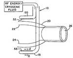
- FIG. 1is a schematic view showing a procedure in accordance with the present invention utilizing ablation elements operatively connected to either a source of RF energy or cryogenic fluid.
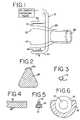
- FIG. 2is a cross-section of an ablation element for use in the present invention taken along lines 2 - 2 of FIG. 1 .
- FIGS. 3-6show alternate configurations for the ablation elements of FIG. 2 .
- FIG. 7shows a further step in the inventive procedure in which tissue is clamped between the ablation elements.
- FIGS. 8-12schematically illustrate the inventive procedure so as to make a transmural lesion that fully circumscribes a pulmonary vein, with FIG. 9 showing a cross-sectional view of the clamp/ablation element in contact with the atrial tissue to express blood from the clamped area.
- FIGS. 13-17show a further method according to the present invention in which transmural lesions are made so as to circumscribe both pulmonary veins.
- FIGS. 18-22show a further procedure in which a transmural lesion is made so as to circumscribe a single pulmonary vein.
- FIGS. 23-27illustrate a further procedure in which a transmural lesion is made so as to circumscribe both pulmonary veins.
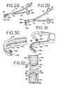
- FIG. 28is a perspective view of a further embodiment of a grasper for use in an open chest procedure in accordance with the present invention showing the grasper in its “closed” position.
- FIG. 29is a perspective view of the grasper of FIG. 28 with the grasper in its “open” position.
- FIG. 30is an enlarged perspective view of the working position of the grasper of FIG. 28 with the grasper jaws in the “closed” position.
- FIG. 31is an enlarged perspective view of the working portion of the grasper of FIG. 28 with the grasper jaws in the “open” position.
- FIG. 32is an enlarged cross-sectional view of the grasper jaws for the grasper of FIG. 28 .
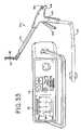
- FIG. 33is a perspective view of a further embodiment of a grasper, which may be used in either an open or a minimally invasive procedure, along with its associated electrosurgical generator.
- FIG. 34is a side view of the grasper of FIG. 33 showing the grasper in its “open” position.
- FIG. 35is an exploded perspective view of the grasper of FIG. 33 .
- FIG. 36is a side cross-sectional view of the grasper of FIG. 33 with the grasper jaws in the “open” position.
- FIG. 37is a side cross-sectional view of the grasper of FIG. 33 with the grasper jaws in the “closed” position.
- FIG. 38is a cross-sectional view taken along line 38 - 38 of FIG. 34 showing the grasper jaws in the “open” position.
- FIG. 39is a cross-sectional view of the grasper jaws taken along the line 39 - 39 of FIG. 37 showing the grasper jaws in the “closed” position.
- FIG. 40is a cross-sectional view of the graspers taken along line 40 - 40 of FIG. 34 .
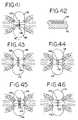
- FIGS. 41-51show alternate constructions for the electrodes suitable for use in the present invention, with FIGS. 41 and 43 - 51 being cross-sectional views similar to FIGS. 38 and 39 , and FIG. 42 being a cross-sectional view taken along line 42 - 42 of FIG. 41 .
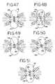
- FIGS. 52A-Killustrate eleven different ablations to the left and right atrium (as seen from behind in FIG. 52A ) and the methods for making the lesions ( FIGS. 52B-K ).
- FIG. 53Ais a perspective view of a further embodiment of device for performing transmural ablation according to the present invention.
- FIG. 53Bis a perspective view of the transmural ablation device of FIG. 53A with a portion removed to show detail.
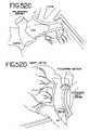
- FIG. 54is an exploded perspective view of the transmural ablation device of FIG. 52 .
- FIG. 55is a longitudinal cross-sectional view of an obturator tip electrode for use in the device of FIG. 52 .
- FIG. 56is a piercing tip electrode for use in the device of FIG. 52 .
- FIG. 57is an enlarged side view of the tip of the instrument shown in FIG. 52 .
- FIGS. 58A-58Gillustrate the use of the instrument of FIG. 52 to form a transmural ablation.
- FIG. 59shows a series of transmural ablations contemplated by the MAZE procedure.
- FIGS. 60A-60Iillustrate a procedure for performing a circumferential lesion in lumen such as a pulmonary vein.
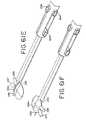
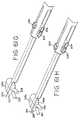
- FIGS. 61A-61Jshow the use of the instrument of FIG. 52 for forming a continuous transmural ablation around a pair of pulmonary veins.
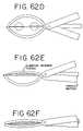
- FIGS. 62A-Ishow a further device for performing transmural ablations and the method for making such ablations.
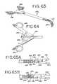
- FIG. 63is a perspective view of a further embodiment of a grasper adapted for use in minimally invasive procedures.
- FIG. 64is an enlarged plan view of the handle position of the grasper of FIG. 63 , with portions removed to show detail.
- FIGS. 65A and 65Bare enlarged plan views of the jaw actuation mechanism for the grasper of FIG. 63 .
- FIG. 66is an enlarged fragmentary perspective view of the jaws of grasper of FIGS. 33-40 .
- FIG. 67is an enlarged perspective view of the tip of the fixed jaw shown in FIG. 66 .
- the compression of the atrial tissueis important because it insures that the exposed electrode surface or cryogenic probe is not in contact with any tissue or blood except the clamped tissue to be ablated.
- the clamping of the tissue between the electrodes or cryogenic probesinsures that the conductive or cooled area is only in contact with the clamped tissue.
- the compressed tissueacts to isolate the electrically active or cryogenically cooled surface, and prevents inadvertent energy delivery to other parts of the heart or blood.
- the outside temperature of the electrodecan easily be monitored to insure that the temperature of the insulation in contact with blood remains below a critical temperature (40° C., for example).
- transmural ablation using RF energyis accomplished by providing an atrial ablation device having a lower “j” clamp/electrode element and placing it on the atrial tissue below the pulmonary veins.
- an upper clamp/electrode elementis introduced, and the clamp assembly “J” is worked back onto the epicardial atrial tissue.
- the tissueis partially clamped, allowing continued flow from the pulmonary veins to the left atrium.
- the clampsare safely away from the pulmonary vein tissue, and onto atrial tissue, the clamps are closed together to compress the tissue.
- bipolar RF energyis used to ablate the clamped atrial tissue.
- the clampsare then removed, the lesion having been created. Lesions may also be created by inserting one clamp/electrode element through an incision in the heart so as to permit contact with endocardial tissue. This incision may be created with a separate instrument. Alternatively, the tip of one of the jaws may have a piercing structure associated therewith for making the entry incision.
- FIG. 1shows a method embodying the present invention.
- a clamping type device 10is provided to group the two walls 22 , 24 of the atrium 20 , and delivers bipolar RF energy through both walls held between the two upper and lower clamp jaws 50 , 51 .
- FIG. 1shows the upper and lower parallel clamp jaws 50 , 51 and electrodes 52 , 53 positioned above and below atrial tissue 22 , 24 , distal to the pulmonary veins.
- FIG. 2Section 2 - 2 of FIG. 1 , shows a cross-section of the clamping member including the insulator 28 and electrode 53 . Alternate configurations of the clamping members are shown in FIGS. 3-6 .
- FIG. 1shows the upper and lower parallel clamp jaws 50 , 51 and electrodes 52 , 53 positioned above and below atrial tissue 22 , 24 , distal to the pulmonary veins.
- FIG. 2Section 2 - 2 of FIG. 1 , shows a cross-section of the clamping member including the insulator 28 and electrode
- FIG. 3shows a cross section of the electrode consisting of an insulating layer 11 , and a conductive strip 12 .
- the electrode of FIG. 3may be constructed of a tungsten wire as the conductive material 12 , with polyamide as the insulating material 11 .
- the conductive stripis created by exposing a part of the tungsten wire through the polyamide.
- FIGS. 4 and 5show an alternate electrode construction consisting of a carbon fiber element 13 , and an insulating material 14 , such as ABS.
- the conductive strip 15may be comprised of a copper/gold electrode plated onto the ABS.
- FIG. 6shows a cross section of yet another possible electrode design where the conductive material 16 consists of a stainless steel needle with lumen 17 and insulating material 18 .
- FIG. 7shows the parallel jaws 50 , 51 clamping and ablating the atrial tissue 20 distal to the pulmonary veins 26 .
- Proximal point Ais clamping and ablating the atrial tissue distal to the pulmonary veins.
- Proximal point Ais the most proximal point of ablated tissue on both the upper and lower atrial wall.
- Distal point Bis the most distal point of ablated tissue on both the upper and lower atrial wall.
- FIGS. 8-12show the inventive procedure that fully circumscribes a pulmonary vein with transmural lesions.
- FIG. 8shows a top view of the instrument jaws positioned for a 2-step isolation of a single pulmonary vein. The lower jaw is directly beneath the upper jaw, and is not shown. Proximal point A and distal point B correspond to FIG. 7 .
- FIG. 9shows a cross-sectional view of the jaws clamping and ablating atrial tissue.
- the electrode/clamp configurationprovides a clamped zone of tissue that is wider than the zone of ablated tissue. This is achieved by using an electrode width that is narrower than the clamped tissue width, and preferably less than one-third of the clamped tissue width.
- the electrodeforms the apex of the triangular clamping member. Other convex shapes are also contemplated.
- an ablation line of tissue on both upper and lower atrial wallsis created. This is shown as ablation line 60 in FIG. 10 .
- the clampis then repositioned to the position shown in FIG. 10 , so that the distal point D overlaps the ablation line 60 .
- the tissueis clamped and ablated as shown in FIGS. 7 and 9 , and a second ablation line 61 ( FIG. 11 ) is formed on both the upper and lower atrial walls.
- Proximal point C and distal point Dcorrespond to points A and B respectively.
- the full ablation lineis shown in FIGS. 11 and 12 with points A-D as shown.
- This “clamping” method and device for creating transmural lesionshas a number of advantages.
- First, using a two step method as shownallows for clamping and ablation of atrial tissue without stopping the blood flow from the pulmonary vein.
- FIGS. 18-22show the clamping device in a curved-jaw embodiment that creates a circumferential lesion around the pulmonary vein in one step.
- FIGS. 18 and 19show the clamp jaws positioned around the pulmonary vein.
- FIGS. 20 and 21show the device clamping and ablating atrial tissue distal to the pulmonary vein.
- FIG. 22shows the resulting ablation line 60 .
- FIGS. 23-27show the same concept applied to a device and method for creating a lesion around both pulmonary veins.
- the advantage of this conceptis that the entire lesion is created in one step.
- the disadvantageis that blood flow from the pulmonary vein(s) is cut off during ablation.
- Using a curved electrodealso allows the user to ablate tissue more distal to the pulmonary vein than would be possible with a straight electrode.
- this curved type electrodecould be used with a two step procedure as described above, using “left” and “right” curved devices to create a lesion which was more distal to the pulmonary veins.
- this method and deviceare not limited to use around the pulmonary veins, but could be used anywhere in the atrium that the clamp could be applied.
- FIGS. 28-32there is seen a further version of a cardiac grasper 70 suitable for an open chest procedure in accordance with the present invention.
- the grasper 70includes two ring handles 72 , 74 joined together for relative movement by a pivot screw or pin 76 .
- Each handle 72 , 74has a jaw member 78 , 80 respectively associated therewith, each jaw being curved so that it has a major portion that is substantially perpendicular to the handles. This gives the grasper 70 an L-shaped appearance, with a working portion of the jaws being between approximately 3-8 cm in length.
- the grasperis made of a rigid material, such as stainless steel, and is substantially encased in a durable insulating material, such as ABS plastic.
- a durable insulating materialsuch as ABS plastic.
- FIG. 32which shows the opposed jaw members in cross section, the stainless steel structural support is designated 82 .
- the structural support 82is completely encased by insulating members 84 , 86 and 88 .
- the tips 78 a , 80 a of the jawsmay be made of a soft, atraumatic material in order to reduce the likelihood of unintentional injury of tissue by the jaws.
- the grasper jawshave raised or convex, opposed tissue clamping surfaces, 90 , 92 , respectively, with each clamping surface, 90 , 92 centrally supporting an electrode 94 , 96 , respectively, of opposite polarity.
- RF energy of opposite polarityis supplied to the electrodes 94 , 96 through conductors 98 , 100 , which are connected to an RF generator.
- this electrode/clamp configurationprovides a clamped zone of tissue that is significantly wider than the zone of ablated tissue created by the opposed electrodes.
- the clampingalso eliminates the cooling effect of circulating blood.
- the electrodes 94 , 96have a T-shaped cross section, with the cross portion of the T resting on the insulating member 88 and the upright portion of the T protruding through a narrow opening in the insulating member 84 , thus creating an exposed electrode surface that contacts the tissue grasped between the jaws.
- the electrodesare preferably made of gold-plated copper and extend along substantially the entire working surface of the jaw members.
- the exposed portions of the electrodeare generally less than 1.25 mm in width, and preferably between approximately 0.12-0.6 mm in width. This insures that most of the jaw surface is insulator, and that the electrode comprises generally less than one-third of the width of the jaw.
- the graspersmay provide feedback that permits the user to gauge the completeness (i.e., degree of transmurality) of the ablation.
- a transmural lesionblocks electrical signals because it is non-conductive scar tissue.
- impedanceis simply the inverse of conductivity, the ability of the lesion to block electrical signals is accurately indicated by its impedance, which can be measured simultaneously with the creation of the lesion.
- the current and voltage applied to the tissueare measured, and the impedance calculated and stored. Based upon a function of the impedance (e.g., its value, the change in value, or the rate of change in value)) it is determined whether ablation is complete and transmural.
- Indicator lights or other types of signalsmay be associated with the grasper to correspond to the degree of ablation determined by the impedance feedback system. For example, once the impedance reaches a certain level for a certain period of time, a red light may be activated to signal that ablation is complete.
- a feedback system for determining the temperature of the ablated tissueis also provided.
- the jawsinclude a series of thermocouples 102 that are supported in the insulating member 84 remote from the associated electrode 94 near the edge of the jaw 78 .
- the thermocouples 102protrude slightly through the surface of the insulating member 84 so as to engage any tissue clamped between the jaws 72 , 74 .
- Wires 104are attached to the thermocouples 102 to transmit the information received to a remote location.
- a visual or other indicatormay be provided to alert the user that a certain pre-determined critical temperature (e.g., 40° C.) has been reached, thus permitting the user to avoid undesired thermal spread.
- FIGS. 33-37there is a further version of a cardiac grasper 110 suitable for both open and minimally-invasive procedures in accordance with the present invention.
- the grasper 110includes a cord 112 for housing the conductors (not shown) and for plugging into an electrosurgical generator 114 to provide current to the grasper 110 .
- the generator 114includes a display 115 to provide a simultaneous visual indication of the degree of conductance of the tissue being ablated.
- the instrument 110includes opposed parallel, curved jaw assemblies 116 , 118 with jaw assembly 116 being fixed and jaw assembly 118 being movable between an open position (as seen in FIGS. 34 and 36 ) to a closed position (shown in FIG. 37 ).
- the fixed jaw assembly 116comprises a fixed electrode 120 , a fixed insulator 122 and a fixed jaw cap 124 .
- the fixed electrode 120provides an electrical pathway adjacent to the tissue to be ablated and is located on the inside of the fixed jaw assembly 116 (the “inside” being defined as the side that contacts the tissue to be ablated).
- the fixed insulator 122surrounds the fixed electrode 120 and forms the inside of the fixed jaw assembly 116 .
- the fixed jaw cap 124forms the backside of the fixed jaw assembly 116 (the “backside” being defined as the surface opposite the fixed electrode 120 ).
- the drive jaw assembly 118comprises a drive electrode 126 , a drive insulator 128 , and a drive jaw cap 130 .
- the drive electrode 126provides a second electrical pathway adjacent the tissue to be ablated and is located on the inside of the drive jaw assembly 118 (“inside” being defined as the side contacting the tissue to be ablated).
- the drive insulator 128surrounds the drive electrode 126 and forms the inside of the drive jaw assembly 118 .
- the drive jaw cap 130forms the backside of the drive jaw assembly 118 (“backside” being defined as the surface opposite the drive electrode 126 ).
- Each of the electrodes 120 , 126is attached to an electrically conductive means, such as a wire, that runs the length of the extension shaft and through the conductor cord 112 for coupling to the RF generator 114 .
- an electrically conductive meanssuch as a wire
- Each jaw assembly 116 , 118is supported by a two piece extension shaft comprising a right fixed member 132 and left fixed member 134 (for the fixed jaw) and a right drive member 136 and left drive member 138 (for the drive jaw 118 ).
- a shaft cap 139covers the coextensive portions of the fixed members 132 , 134 and the drive members 136 , 138 (when the jaws are in the open position as seen in FIG. 34 ).
- the right fixed member 132 and left fixed member 134combine to form a structure that extends from a handle 140 , through the shaft cap 139 , and then terminating at the distal end of the instrument 110 in the fixed jaw assembly 116 on the right and left sides, respectively, of the instrument.
- the right drive member 136 and left drive member 138extend from the handle 140 , through the shaft cap 139 , and then terminate in the drive jaw assembly 118 on the right and left sides, respectively, of the instrument.
- the portions of the fixed members 132 , 134 co-extensive with the fixed jaw assembly 116are joined by a fixed bridge 142 along the length of the jaw.
- the portions of the drive members 136 , 138 co-extensive with the drive jaw assembly 118are joined together by a drive bridge 144 along the length the drive jaw 118 .
- the handle 140comprises two mating halves 140 a , 140 b for encapsulating the actuation and force control mechanisms for the grasper, as well as providing for grounding of the shaft components by means of a conductive shaft pin 141 .
- the handle 140includes a lever comprising a pair of lever plates 146 and a lever shroud 148 .
- the leveris pivotally mounted on a support member 150 extending between the two halves 140 a , 140 b of the handle 140 , with a lever spring 151 biasing the lever to its open position ( FIG. 34 ).
- the lever plates 146are coupled by a lever pin 152 to a carriage 154 that captures the proximal ends of the drive members 136 , 138 , so as to provide translational motion to these members.
- the carriage 154includes a lost motion assembly comprising a carriage spring 156 for controlling the minimum and maximum loads that can be applied to tissues that are to be captured between the jaw assemblies 116 , 118 .
- a lost motion assemblycomprising a carriage spring 156 for controlling the minimum and maximum loads that can be applied to tissues that are to be captured between the jaw assemblies 116 , 118 .
- the thicker the tissue that is grasped between the jawsthe greater the compression of the spring 156 , and the greater the compression force exerted by the jaws on the tissue. (The range of tissue thickness is expected to be between about 1-15 mm.) Adjustment of the compression force is accomplished by pre-loading the carriage spring 156 with a load adjustment screw 158 .
- the lost motion assemblyalso includes a thumb latch 160 for releasing the clamping pressure and for providing a mechanical stop for the spring-loaded carriage 154 .
- the thumb latch 160is pivotally mounted on a latch pin 162 to secure the thumb latch to the handle 140 . Additionally, a latch spring 164 is provided for biasing the thumb latch 160 to its locked position. A latching step on the carriage 154 interfaces with the tip of the thumb latch 160 to provide for the mechanical stop.
- the tissueis first placed between the open instrument jaws 116 , 118 .
- the usergrasps the actuation lever comprising the lever plates 146 and lever shroud 148 to apply the force required to drive the drive members 136 , 138 and drive jaw assembly 118 distally, thus compressing the tissue and automatically engaging the thumb latch 160 .
- the thumb latch 160locks the position of the drive members 136 , 138 and the drive jaw assembly 118 with respect to the handle 140 and the fixed jaw assembly 116 .
- the amount of jaw force on the tissueis controlled by the lost motion assembly between the lever and the drive members 136 , 138 .
- the operatoractivates the RF generator 114 .
- RF energypasses through the tissue between the electrodes 120 , 126 , thus ablating the tissue between these electrodes.
- the operatorreleases the clamping of the tissue by depressing the thumb latch 160 , thus releasing the carriage 154 .
- the lever spring 151drives the drive members 136 , 138 and the drive jaw assembly 118 proximally to their open positions.
- the actuation leversince it is directly coupled to the carriage 154 , also returns to the open position.
- FIGS. 41-51there is seen in schematic form various configurations for the electrodes 120 , 126 for use in conjunction with the grasper 110 .
- FIGS. 41 and 43 - 51show a cross-section through the instrument jaws as clamped on the tissue to be ablated.
- Each electrodeis formed of a piece of electrically conductive metal that may be plated with a biocompatible material.
- the electrode geometryconsists of a largely rectangular electrode with a window of material removed from the central region.
- the window areais filled with the insulator material 122 , 128 .
- the electrode insulator materialleads away from the electrode on a radius.
- the electrode materialprotrudes outside the clamping surface of the insulating material. However, the electrode may also be flush with the clamping surface.
- the electrode geometryis largely rectangular and the electrode insulator material leads away from the electrode on a radius.
- the electrodeis flush with the clamping surface of the insulator material.
- the electrodeis applied to fill a groove in the insulator material by way of a plating process.
- the electrode geometryis largely rectangular and the electrode insulator material leads away from the electrode on a radius.
- the electrode platingis largely flush with the clamping surface of the insulator material.
- the electrodeis formed into a U-shaped element.
- the electrode insulator materialleads away from the electrode on a radius. As shown, the electrode material extends outside the clamping surface of the insulator material. However, the electrode material may also be flush with the insulator clamping surface.
- the electrodeis applied to fill a groove in the insulator material by way of a plating process, with the electrode geometry being largely rectangular.
- the electrode insulator materialcreates a small flat surface perpendicular to the closure plane that is largely flush with the surface of the plate or electrode. As shown, the electrode material is flush with the clamping surface of the insulator material. However, the electrode material may also be applied so that it extends outside the insulator clamping surface.
- the electrode geometryis largely rectangular and the electrode insulator material leads away from the electrode on a radius.
- the electrode materialextends outside the clamping surface of the insulator material.
- the electrode configurationis again largely rectangular, with the electrode insulator material creating a small flat surface perpendicular to the closure plane that is largely flush with the surface of the plate or electrode.
- the electrodeis flush with the clamping surface of the insulator material and a temperature sensing means, such as a thermocouple 166 (see also FIGS. 35 and 39 ), is positioned in close proximity to the electrode, but electrically isolated from the RF energy.
- the electrodeis applied to fill a groove in the insulator material by way of a plating process.
- the electrode geometryis largely rectangular and the electrode insulator material leads away from the electrode on a radius.
- the electrodeis applied to the surface of the electrode insulator material by way of a plating process.
- the electrode geometryis largely rectangular with the electrode insulator material leading away from the electrode on a radius.
- the electrode platingis largely flush with the clamping surface of the insulator material.
- the electrodeis round wire made from an electrically conductive metal that may be plated with a biocompatible material.
- the electrode insulator materialleads away from the electrode on a radius. As shown, the electrode material extends outside the clamping surface of the insulator material. However, the electrode material may also be flush with the insulator clamping surface.
- FIGS. 63-65A further embodiment of a grasper according to the present invention is shown in FIGS. 63-65 and is designated generally 250 .
- the grasper 250has jaws 252 , 254 similar in structure to those described above in connection with the embodiments of FIGS. 28-32 and 33 - 40 , but includes a different actuation mechanism.
- the jaws 252 , 254 of the grasper 250are biased so that they are normally in the closed position, the jaws being moved to the open position by moving the two handle members 256 , 258 towards each other. This action serves to withdraw a push-rod 260 ( FIG. 64 ), which is pivotally connected to the handle members 256 , 258 by links 262 , 264 .
- FIG. 65A and FIG. 65BWith reference to FIG. 65A and FIG. 65B .
- the distal end of the push rod 260includes two pins 266 , 268 which are captured in slots 270 , 272 in their respective jaw members 252 , 254 .
- the pins 266 , 268are located in the distal ends of the slots 270 , 272 , the jaws are in the closed position.
- the jaws 252 , 254open as the pins 266 , 268 move proximally in the slots 270 , 272 through the withdrawal of the push rod 260 by the closing of the handle members 256 , 258 .
- the jaws 252 , 254also include a lost motion connection including a spring to bias the jaws toward the closed position.
- the jaws 252 and 254are pivotally connected to each other by means of a pin 274 .
- the pin 274is secured to the jaw member 254 , but is received in an elongated slot 276 in jaw member 252 .
- the pin 274is biased to the top of the slot 276 , thus biasing the jaws 252 , 254 to the closed position, by means of a leaf spring 278 having one end secured to the pin 274 and the other end captured between two studs 280 , 282 carried on the jaw member 252 .
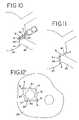
- FIGS. 52A-Killustrate a series of 11 different lesions or ablations that may be made using either an open or a minimally invasive technique with the graspers described above.
- FIG. 52Athere is seen a view of the heart showing the right and left atriums (as viewed from behind).
- the heartincludes the left atrial appendage (LAA) and the right atrial appendage (RAA).
- the right pulmonary veins (RPVs) and left pulmonary veins (LPVs)enter into the top of the left atrium.
- the superior vena cava (SVC) and inferior vena cava (IVC)are also shown.
- the mitral valve annulusis designated as MVA, while the tricuspid valve annulus designated TVA.
- MVAthe tricuspid valve annulus
- FIGS. 52A11 different lesions are indicated by the reference numerals 1 - 11 .
- a method for making each of these lesionsis illustrated in the following FIGS. 52B-K . It should be appreciated that, depending upon a particular patient's indications, the lesions 1 - 11 may be created in a variety of combinations.
- FIG. 52Ba method for making lesion 1 to circumscribe the right pulmonary veins (RPVs) is shown. This lesion is made completely epicardially in a manner similar to that illustrated in FIGS. 23-27 .
- FIG. 52Cillustrates lesion 2 , an epicardial ablation that fully circumscribes the left pulmonary veins (LPVs). Again, this lesion may be made in a manner similar to that illustrated in FIGS. 23-27 .
- FIG. 52Dillustrates a method for making lesion 3 , which connects lesions 1 and 2 .
- Lesion 3is made with only one of the jaws of the graspers being located epicardially.
- the mating jawis inserted into the interior of the heart through a small incision which is sealed using a purse-string suture.
- the incision as illustratedis made interior the lesion 1 encircling the right pulmonary veins (RPVs).
- RSVsright pulmonary veins
- Lesion 4connects the lesion 1 , which surrounds the right pulmonary veins, to the mitral valve annulus (MVA). It may be made through the same incision and purse-string suture used for making lesion 3 . With reference again to FIG. 52D , the jaws of the grasper are merely rotated down so that the distal end of the jaw overlies the mitral valve annulus.
- the distal tip of one of the jaw members of the grasperincludes an EKG sensor so that the EKG of the tissue contacted by the tip of the grasper can be monitored.
- the distal tip of the fixed jaw 116includes a pair of laterally-opposed bipolar EKG electrodes or sensors 168 spaced slightly distally from the distal-most end of the electrode 120 .
- the sensors 168are connected to conductive leads 170 ( FIG. 33 ) that are adapted to be connected to an EKG monitor (not shown) to provide a display of the EKG.
- the surgeoncan constantly monitor the EKG, looking for the change from an atrial EKG to a ventricular EKG, to facilitate accurate placement of the jaw tip on the mitral valve annulus, and away from the mitral valve leaflets.
- SVCsuperior vena cava
- IVCinferior vena cava
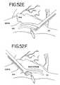
- an incision with purse-string sutureis made approximately midway between the SVC and IVC, with one of the jaws of the grasper being inserted into the incision so as to have its end adjacent the base of the SVC.
- the lesion 5is formed and then the instrument is rotated 180° as shown in FIG. 52F , to make lesion 6 .
- Lesion 7may conveniently be made through the same incision and purse-string suture as lesions 5 and 6 , as shown in FIG. 52G .
- Lesion 7extends from between the SVC and IVC out toward the right atrial appendage (RAA).
- RAAright atrial appendage
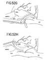
- a lesion 8is made between the right atrial appendage and the tricuspid valve annulus (TVA) utilizing an incision and purse-string suture made in the RAA, as illustrated in FIG. 52H .
- Lesion 8is made on the opposite side of the right atrium as lesion 7 , and thus is shown in dotted line in FIG. 52A .
- a lesion 9may also be made circumscribing the right atrial appendage so as to intersect both lesions 7 and 8 .
- lesion 9is made epicardially.
- a similar epicardial ablation circumscribing the left atrial appendageis designated 10 and illustrated in FIG. 52J .
- a final lesion 11is illustrated that connects lesion 10 circumscribing the left atrial appendage with lesion 2 that circumscribes the left pulmonary veins.
- the lesion 11is made utilizing an incision and purse string suture through which the grasper jaw is introduced, the incision being located in the left atrial appendage beyond the lesion 10 .
- the present deviceconsists of two long, linear, wire-type electrodes, which are in parallel relationship to each other, each approximately 1 mm in diameter, and 50 mm long.
- the electrodesare insulated along their entire surface with a thin layer of high dielectric material such as polyamide, except for a thin strip of electrically conductive material that runs along the length of each electrode, in face-to-face relationship with each other.
- the electrodesare comprised of a high modulus material, such as tungsten or carbon fiber.
- One of the electrodesis designed to be introduced into the interior of a hollow organ through a small puncture wound in the wall of the organ.
- the second electrodeis introduced on the opposite side of the hollow organ wall.
- the deviceincorporates a mechanism for advancing each electrode individually, or both simultaneously, in parallel relation with each other.
- the devicealso includes a clamping mechanism that brings the two electrodes together so that their exposed conductive surfaces are in face-to-face relation and the electrodes exert sufficient pressure to clamp the tissue.
- the clamping mechanismis activated which brings the two wires together, and clamps the tissue between the two exposed electrode surfaces.
- RF energyis then applied between the two electrodes, and the tissue is ablated in a long, continuous, transmural line.
- a monitoring devicemeasures the voltage, current, impedance, and/or temperature between the two electrodes, and an algorithm determines whether the tissue is fully ablated.
- This deviceprovides a way to achieve and verify a fully transmural and continuous line of tissue ablation by locating the atrial tissue between two bipolar wire electrodes, and clamping the tissue.
- the forcepsconsist of two electrode pads of opposite polarity designed to grasp and clamp tissue.
- a well-known method of determining the status of the tissue between the electrode padsis to monitor the current, voltage, and impedance of the tissue, as done using the Richard Wolf generator for bipolar forceps. It is well known in the art that the ablative status of tissue clamped between two bipolar electrodes can easily be determined by monitoring the increase in tissue impedance as the tissue dessicates.
- This deviceis to be used with an RF generator that monitors current, voltage, and impedance to determine the state of tissue ablation of the tissue compressed between the inner and outer electrodes.
- the RF generatorwill be equipped with an indicator which informs the user of the status of the clamped tissue, and when ablation is complete (i.e., transmural along the entire length of the electrodes).
- This deviceprovides the capability of creating long, transmural lesions through atrial wall tissue of varying thickness because it employs an active bipolar electrode on each side of the atrial wall, and the ablation proceeds from both the inside and outside of the atrial wall.
- the deviceis also unique in that the electrodes are used to compress the tissue to be ablated. This compression is critical because the inside and outside surfaces of the atrium can have irregularities, and a high clamping pressure insures that both electrodes are making good contact with tissue along the full length of each electrode. Clamping the tissue also reduces the distance between the electrodes, and makes the ablation more efficient because the electrical energy is more concentrated. Because of this higher concentration of energy, lower powers and temperatures can be used to achieve complete ablation, and the process is considerably faster.
- the deviceconsists of an inner wire electrode wire electrode 201 , an outer wire electrode 202 , an inner slider button 203 , an outer slider button 204 , and a clamping slider tube 205 and button 206 .
- the device body 207houses the wire electrodes, slider tube and buttons, connector wires 207 a and 208 , and bipolar connector 209 .
- the devicemay also include slit needle introducer tip 210 .
- the operation of the devicebegins by advancing the inner electrode wire 201 by advancing the slider button 203 .
- the outer electrode 202is advanced by advancing slider button 204 .
- further advancement of slider button 204also advances slider button 203 , so that both electrodes 201 and 202 advance simultaneously.
- the slider tubeadvances along with the outer electrode 202 .
- the slider tube 205is advanced so that the end 205 b of the slider tube 205 contacts the arcuate wire segment 202 b of electrode wire 202 . Further advancement of slider tube 205 acts to compress the electrode wires 201 and 202 together along the entire effective length L.
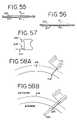
- FIGS. 55 and 56show two types of electrode wires, a piercing tip ( FIG. 56 ), and an obturator, or blunt tip ( FIG. 55 ).
- the electrodesmay be similar in construction to those shown in FIGS. 2-6 , which are described above.
- FIG. 57shows a side view of the instrument tip.
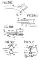
- FIG. 58Ashows the instrument used to penetrate the wall of a hollow organ, such as the heart.
- the slit needle 210penetrates tissue through the wall of the atrium 218 .
- the inner wire electrode 201is advanced through the puncture wound into the interior of the atrium.
- the outer needle 202is initially advanced onto the external surface of the atrial wall 218 .
- FIG. 58Dshows the inner 201 and outer 202 needles as they are simultaneously advanced along the inner and outer surfaces of the atrial wall 218 .
- FIG. 58Eshows the pusher tube 205 advanced to compress the tissue of the atrial wall 218 at location 219 .
- FIG. 58Fshows section B-B of FIG. 58E , with the inner 201 and outer 202 electrodes compressing the tissue 219 .
- the area of ablated tissueis shown as 220 .
- the alternate electrode configuration of FIG. 5is shown in FIG. 58G .
- Blood cellsare represented as 221 .
- the compression of the tissueis important because it insures that the exposed electrode surface is not in contact with any tissue or blood except the clamped tissue to be ablated. Referring to FIGS. 58F and 58G one can see that the clamping of the tissue between the electrodes insures that only the conductive area is in contact with the clamped tissue. Especially important is avoiding any contact between the conductive area of the electrode and blood in the atrium. Contact between an active electrode and blood in the atrium is major cause of thrombus formation in ablation procedures.
- the compressed tissueacts to isolate the electrically active surface, and prevents inadvertent energy delivery to other parts of the heart or blood.
- the outside temperature of the electrodecan easily be monitored to insure that the temperature of the insulation in contact with blood remains below a critical temperature (40° C., for example).
- FIG. 59shows a potential series of continuous transmural ablation lines 222 located around the pulmonary veins 223 in the left atrium 224 .
- a series of puncture wounds 225are shown as one means to achieve the pattern of ablation lines (shown in dot-dash lines).
- FIG. 60Ashows a method for achieving a circumferential lesion in a pulmonary vein 223 .
- the inner needle 201is a piercing tip as shown in FIG. 56 .
- the needleis advanced completely through the wall of the pulmonary vein until it exits the vein.
- the outer electrode 2is advanced parallel to the inner electrode 201 .
- the electrodesare compressed, and the compressed vein wall tissue 226 is ablated by applying RF energy between the two electrodes.
- FIG. 60Dthe electrodes are released, and the vein wall tissue 226 returns to its original shape.
- FIG. 60Eshows the outer electrode 202 retracted back into the instrument body, and the instrument is rotated 180 degrees about the axis of electrode 201 .
- FIG. 60Fshows the outer electrode 202 advanced along the opposite side of the pulmonary vein from the ablated tissue 220 .
- the electrodesare compressed, and the compressed vein wall tissue 227 is ablated by applying RF energy between the electrodes.
- FIG. 60Hshows the position of the electrodes with the pusher tube retracted, and the fully circumferential lesion 220 .
- FIG. 60Ishows the instrument retracted from the vein, and the circumferential lesion of ablated tissue 220 .
- FIGS. 61A-61Jshow the instrument used in a method to create a circumferential lesion around a pair of pulmonary veins 226 and 227 .
- the inner electrode 201is advanced into the side of the atrial wall 218 , just below the ostium of the pulmonary vein 226 by advancing slider button 203 .
- FIG. 61Bshows electrode 201 and slider 203 fully advanced, and exiting the atrial tissue 218 just below the ostium of pulmonary vein 227 .
- FIG. 61Cshows outer electrode 202 advanced fully in parallel and to the same length as inner electrode 201 by advancing slider 204 . Note that slider tube button 205 has advanced to its intermediate position.
- FIG. 61Dshows slider button 205 fully advanced, which clamps electrodes 201 and 202 together just below the ostia of the pulmonary veins on the side of the veins indicated by tissue surface 218 a , and compresses the atrial wall tissue. RF energy is then applied between the two electrodes, and the clamped tissue 219 is ablated.
- electrode 202is retracted by retracting slider button 4 .
- the line of ablated tissueis shown as 219 a .
- This line of ablated tissue 219 awill be completely continuous and transmural, and connect inner needle entry point 229 with inner needle exit point 230 and extend along the side of the atrial wall.
- FIG. 61Fshows the device body 207 rotated 180 degrees about the axis of the inner electrode 201 so that the atrial surface 218 b on the opposite side of the pulmonary veins is exposed.
- FIG. 61Gshows slider button 204 and outer electrode 202 advanced over the opposite surface of the atrium 218 b .
- FIG. 61Hshows slider button 205 advanced, and the electrodes 201 and 202 clamping the tissue 219 b just below the ostia of the pulmonary veins 226 and 227 along atrial wall 218 b .
- RF energyis then applied between the electrodes 201 and 202 to ablate the compressed tissue 219 b .
- the slider button 205is retracted, and the electrodes release the tissue 219 b .
- FIG. 16Jshows a top view of FIG. 61I showing the continuous line of ablated tissue surrounding pulmonary veins 226 and 227 , connected by entry point 229 and exit point 230 of internal electrode 201 .
- the electrodeis then retracted, leaving a continuous transmural lesion that electrically isolates the pulmonary veins from the rest of the atrial tissue.
- a penetrating compressive/tensile electrodeis used. Once the jaws are positioned below the ostia of the pulmonary veins, the tissue is partially clamped, allowing continued flow from the pulmonary veins to the left atrium. An electrode needle is introduced which enters the left side of the atrial tissue and exits on the right side into a tip securing point on the lower jaw. This point will prevent the tip from moving axially when a needle is pushed. The lower atrial tissue can be compressed by “pushing” on the needle with a force that compresses tissue between the needle electrode and the lower jaw electrode. Bipolar RF energy is then applied between the needle and lower jaw electrodes to ablate a line of tissue from the needle entry to exit point.
- the upper jawis moved down to contact the tip of the lower jaw. Note that this still provides an open lumen for blood flow from the pulmonary veins to the left atrium.
- the needleis rotated 180 degrees on its axis so that the electrode surface faces up.
- the needleis then “pulled” to create tension, and exert a compressive force that compresses tissue between the needle electrode and the upper jaw.
- Bipolar RF energyis then applied between the needle electrode and upper jaw to ablate the tissue. Note that the partial closing of the upper jaw to contact the tip of the lower jaw could be done prior to compressing the lower atrial tissue.
- FIGS. 62A-62Ithe clamping apparatus as generally described above is shown.
- the deviceis a “pliers type” apparatus.
- the deviceis shown clamped around the atrial tissue below the ostia of the pulmonary veins.
- an electrode needleis advanced through the atrial tissue to contact a receiver at the tip of the device.
- FIG. 62Eshows one method of clamping the tissue to a rigid needle electrode, using a non-rigid outer clamping member that flexes either by further motion of the handle as shown or by further extension of the electrode member.
- FIG. 62Fshows both sides of the clamping member flexed, and the tissue compressed between.
- FIG. 62Gshows the position of the clamping members and electrode prior to tissue clamping.
- FIG. 62Hshows these positions during tissue clamping.
- Bipolar RF energyis applied between the clamping members, and the inner electrode to ablate the atrial tissue, creating a lesion, as shown in FIG. 62H .
- the tissue ablationcould be carried out first on one side, then the other, without occluding the lumen between the pulmonary veins and the atrium.
- FIG. 62Ishows another way to achieve tissue compression by advancing a relatively flexible needle electrode which bends as shown to compress the tissue between the electrode and one of the device jaws.
- transmural ablation device and methodhave been provided that overcome the limitations of the prior art.
- current technologyinvolves ablation devices deliver ablation energy to either the inside (endocardium) or outside (epicardium) of the heart.
- the tissue ablationproceeds from one wall of the heart through the tissue to the opposite wall.
- transmural lesionsthere has been no reliable way to consistently achieve lesions that penetrate the full thickness of the atrial wall (transmural lesions), and there has been no way to determine either continuity or transmurality of these lesions. If the lesion does not penetrate through enough of the atrial wall, conduction can still occur, and the lesion does not fully block the electrical signals that are causing the arrhythmia.
- the present inventionovercomes these shortcomings because the conductive area of each electrode is very narrow compared to the width of the clamped area. As a result, the thermal damage to the tissue is minimal.
- current technologyuses catheter electrodes which are typically 1 or 2 mm diameter requiring a lesion width of almost 8 mm to achieve a depth of 5 mm.
- catheter electrodeswhich are typically 1 or 2 mm diameter requiring a lesion width of almost 8 mm to achieve a depth of 5 mm.
- a lesion depth of 5 mm with a width of less than 2 mmcan be achieved.
- This aspect of the inventionallows for longer linear lesions with less power delivery because less tissue is being heated. There is, therefore, considerably less damage to healthy atrial tissue for a lesion of a given depth and length.
- Recent efforts in creating linear lesions using endocardial electrodesresulted in ablation of over 20% of the atrial endocardium, and a commensurate decrease in atrial contractility.
- Another advantage of this deviceis that ablation can be done on a beating heart. Using a high modulus material such as tungsten or carbon fiber would allow a minimum diameter, and a maximum clamping pressure for a given clamping length. Once the device is clamped onto the atrial wall, the position of the electrodes can be verified by visually inspecting the position of the outer electrode before delivery of RF energy. If the clamping pressure is higher than the atrial pressure, then clamping over a coronary artery would cut off blood flow, and the resulting change in the EKG would act as a warning to the user prior to applying RF energy. The clamping will prevent any movement of the electrodes relative to the heart wall, and RF energy can be applied with confidence that the ablated tissue will be contained completely between the two electrodes.
- a high modulus materialsuch as tungsten or carbon fiber would allow a minimum diameter, and a maximum clamping pressure for a given clamping length.
- Another important feature of this deviceis that the energy transfer is limited to the tissue clamped between the two electrodes.
- the insulated electrodesprotect structures on the outside of the heart from being exposed to RF energy. Because of this limitation of current flow, damage to critical structures can be avoided.
- Another advantage of this deviceis that it can easily be adapted to a minimally invasive thoracoscopic approach.
- the device shownhas been reduced to a 5 mm diameter device, and can probably be reduced to 3 mm or less.
- the devicecould be introduced through a small intracostal incision, and used to create fully transmural linear lesions on a beating heart, possibly under local anesthesia on an anesthetized patient.
Landscapes
- Health & Medical Sciences (AREA)
- Surgery (AREA)
- Engineering & Computer Science (AREA)
- Life Sciences & Earth Sciences (AREA)
- Biomedical Technology (AREA)
- Otolaryngology (AREA)
- Nuclear Medicine, Radiotherapy & Molecular Imaging (AREA)
- Plasma & Fusion (AREA)
- Physics & Mathematics (AREA)
- Heart & Thoracic Surgery (AREA)
- Medical Informatics (AREA)
- Molecular Biology (AREA)
- Animal Behavior & Ethology (AREA)
- General Health & Medical Sciences (AREA)
- Public Health (AREA)
- Veterinary Medicine (AREA)
- Surgical Instruments (AREA)
Abstract
Description
Claims (17)
Priority Applications (1)
| Application Number | Priority Date | Filing Date | Title |
|---|---|---|---|
| US10/928,826US7468061B2 (en) | 2000-04-27 | 2004-08-27 | Transmural ablation device with integral EKG sensor |
Applications Claiming Priority (5)
| Application Number | Priority Date | Filing Date | Title |
|---|---|---|---|
| US20007200P | 2000-04-27 | 2000-04-27 | |
| US09/747,609US6546935B2 (en) | 2000-04-27 | 2000-12-22 | Method for transmural ablation |
| US09/844,225US6517536B2 (en) | 2000-04-27 | 2001-04-27 | Transmural ablation device and method |
| US10/032,378US6932811B2 (en) | 2000-04-27 | 2001-10-26 | Transmural ablation device with integral EKG sensor |
| US10/928,826US7468061B2 (en) | 2000-04-27 | 2004-08-27 | Transmural ablation device with integral EKG sensor |
Related Parent Applications (1)
| Application Number | Title | Priority Date | Filing Date |
|---|---|---|---|
| US10/032,378ContinuationUS6932811B2 (en) | 2000-04-27 | 2001-10-26 | Transmural ablation device with integral EKG sensor |
Publications (2)
| Publication Number | Publication Date |
|---|---|
| US20050033284A1 US20050033284A1 (en) | 2005-02-10 |
| US7468061B2true US7468061B2 (en) | 2008-12-23 |
Family
ID=21864643
Family Applications (2)
| Application Number | Title | Priority Date | Filing Date |
|---|---|---|---|
| US10/032,378Expired - LifetimeUS6932811B2 (en) | 2000-04-27 | 2001-10-26 | Transmural ablation device with integral EKG sensor |
| US10/928,826Expired - Fee RelatedUS7468061B2 (en) | 2000-04-27 | 2004-08-27 | Transmural ablation device with integral EKG sensor |
Family Applications Before (1)
| Application Number | Title | Priority Date | Filing Date |
|---|---|---|---|
| US10/032,378Expired - LifetimeUS6932811B2 (en) | 2000-04-27 | 2001-10-26 | Transmural ablation device with integral EKG sensor |
Country Status (3)
| Country | Link |
|---|---|
| US (2) | US6932811B2 (en) |
| AU (1) | AU2002356846A1 (en) |
| WO (1) | WO2003037162A2 (en) |
Cited By (5)
| Publication number | Priority date | Publication date | Assignee | Title |
|---|---|---|---|---|
| US20100152728A1 (en)* | 2008-12-11 | 2010-06-17 | Park Christopher J | Method and apparatus for determining the efficacy of a lesion |
| US9144431B2 (en) | 2009-09-30 | 2015-09-29 | Aegis Medical Innovations Inc. | Enhanced signal navigation and capture systems and methods |
| US9198683B2 (en) | 2009-09-30 | 2015-12-01 | Aegis Medical Innovations, Inc. | Tissue capture and occlusion systems and methods |
| US9848898B2 (en) | 2008-03-27 | 2017-12-26 | Mayo Foundation For Medical Education And Research | Navigation and tissue capture systems and methods |
| US11678928B2 (en) | 2019-01-10 | 2023-06-20 | Atricure, Inc. | Surgical clamp |
Families Citing this family (133)
| Publication number | Priority date | Publication date | Assignee | Title |
|---|---|---|---|---|
| US5836311A (en) | 1995-09-20 | 1998-11-17 | Medtronic, Inc. | Method and apparatus for temporarily immobilizing a local area of tissue |
| US6096037A (en) | 1997-07-29 | 2000-08-01 | Medtronic, Inc. | Tissue sealing electrosurgery device and methods of sealing tissue |
| US7226446B1 (en) | 1999-05-04 | 2007-06-05 | Dinesh Mody | Surgical microwave ablation assembly |
| US6277113B1 (en) | 1999-05-28 | 2001-08-21 | Afx, Inc. | Monopole tip for ablation catheter and methods for using same |
| US7033352B1 (en) | 2000-01-18 | 2006-04-25 | Afx, Inc. | Flexible ablation instrument |
| US6447443B1 (en) | 2001-01-13 | 2002-09-10 | Medtronic, Inc. | Method for organ positioning and stabilization |
| US20020107514A1 (en) | 2000-04-27 | 2002-08-08 | Hooven Michael D. | Transmural ablation device with parallel jaws |
| US6546935B2 (en) | 2000-04-27 | 2003-04-15 | Atricure, Inc. | Method for transmural ablation |
| US6905498B2 (en) | 2000-04-27 | 2005-06-14 | Atricure Inc. | Transmural ablation device with EKG sensor and pacing electrode |
| US6932811B2 (en)* | 2000-04-27 | 2005-08-23 | Atricure, Inc. | Transmural ablation device with integral EKG sensor |
| US20020087151A1 (en) | 2000-12-29 | 2002-07-04 | Afx, Inc. | Tissue ablation apparatus with a sliding ablation instrument and method |
| US7628780B2 (en) | 2001-01-13 | 2009-12-08 | Medtronic, Inc. | Devices and methods for interstitial injection of biologic agents into tissue |
| US20040138621A1 (en) | 2003-01-14 | 2004-07-15 | Jahns Scott E. | Devices and methods for interstitial injection of biologic agents into tissue |
| US7740623B2 (en) | 2001-01-13 | 2010-06-22 | Medtronic, Inc. | Devices and methods for interstitial injection of biologic agents into tissue |
| US6776784B2 (en) | 2001-09-06 | 2004-08-17 | Core Medical, Inc. | Clip apparatus for closing septal defects and methods of use |
| US20060052821A1 (en) | 2001-09-06 | 2006-03-09 | Ovalis, Inc. | Systems and methods for treating septal defects |
| US6702835B2 (en) | 2001-09-07 | 2004-03-09 | Core Medical, Inc. | Needle apparatus for closing septal defects and methods for using such apparatus |
| US7099717B2 (en)* | 2002-01-03 | 2006-08-29 | Afx Inc. | Catheter having improved steering |
| US7192427B2 (en) | 2002-02-19 | 2007-03-20 | Afx, Inc. | Apparatus and method for assessing transmurality of a tissue ablation |
| DE60225343T2 (en)* | 2002-02-22 | 2009-02-19 | Bombardier Recreational Products Inc., Valcourt | 3-WHEELED VEHICLE WITH TWO-WAY COOLER AND INTERIOR STORAGE BOX |
| US20090024124A1 (en)* | 2005-07-14 | 2009-01-22 | Lefler Amy | Methods for treating the thoracic region of a patient's body |
| US9949789B2 (en) | 2002-03-05 | 2018-04-24 | Avent, Inc. | Methods of treating the sacroiliac region of a patient's body |
| US20060259026A1 (en)* | 2005-05-05 | 2006-11-16 | Baylis Medical Company Inc. | Electrosurgical treatment method and device |
| US7819869B2 (en)* | 2004-11-15 | 2010-10-26 | Kimberly-Clark Inc. | Methods of treating the sacroilac region of a patient's body |
| US20070156136A1 (en)* | 2002-03-05 | 2007-07-05 | Neil Godara | Methods of treating the sacroiliac region of a patient's body |
| US11291496B2 (en) | 2002-03-05 | 2022-04-05 | Avent, Inc. | Methods of treating the sacroiliac region of a patient's body |
| US9364281B2 (en)* | 2002-03-05 | 2016-06-14 | Avent, Inc. | Methods for treating the thoracic region of a patient's body |
| US9216053B2 (en)* | 2002-03-05 | 2015-12-22 | Avent, Inc. | Elongate member providing a variation in radiopacity |
| US7291161B2 (en)* | 2002-10-02 | 2007-11-06 | Atricure, Inc. | Articulated clamping member |
| US7288092B2 (en) | 2003-04-23 | 2007-10-30 | Atricure, Inc. | Method and apparatus for ablating cardiac tissue with guide facility |
| US7819860B2 (en)* | 2003-06-10 | 2010-10-26 | Medtronic Cryocath Lp | Surgical clamp having trasmurality assessment capabilities |
| US7044946B2 (en)* | 2003-06-10 | 2006-05-16 | Cryocath Technologies Inc. | Surgical clamp having treatment elements |
| US8398632B1 (en)* | 2003-06-10 | 2013-03-19 | Medtronic Cryocath Lp | Surgical clamp having treatment elements |
| US7232437B2 (en)* | 2003-10-30 | 2007-06-19 | Medical Cv, Inc. | Assessment of lesion transmurality |
| US7399272B2 (en) | 2004-03-24 | 2008-07-15 | Medtronic, Inc. | Methods and apparatus providing suction-assisted tissue engagement |
| US7530980B2 (en) | 2004-04-14 | 2009-05-12 | Atricure, Inc | Bipolar transmural ablation method and apparatus |
| US8333764B2 (en) | 2004-05-12 | 2012-12-18 | Medtronic, Inc. | Device and method for determining tissue thickness and creating cardiac ablation lesions |
| WO2005120376A2 (en) | 2004-06-02 | 2005-12-22 | Medtronic, Inc. | Ablation device with jaws |
| WO2005120374A1 (en)* | 2004-06-02 | 2005-12-22 | Medtronic, Inc. | Compound bipolar ablation device and method |
| US8932208B2 (en) | 2005-05-26 | 2015-01-13 | Maquet Cardiovascular Llc | Apparatus and methods for performing minimally-invasive surgical procedures |
| US8579936B2 (en) | 2005-07-05 | 2013-11-12 | ProMed, Inc. | Centering of delivery devices with respect to a septal defect |
| AU2006269738A1 (en)* | 2005-07-14 | 2007-01-18 | Kimberly-Clark Inc. | Electrosurgical device and methods |
| US7846179B2 (en) | 2005-09-01 | 2010-12-07 | Ovalis, Inc. | Suture-based systems and methods for treating septal defects |
| US8550743B2 (en)* | 2005-09-30 | 2013-10-08 | Medtronic, Inc. | Sliding lock device |
| US7662177B2 (en) | 2006-04-12 | 2010-02-16 | Bacoustics, Llc | Apparatus and methods for pain relief using ultrasound waves in combination with cryogenic energy |
| US7794387B2 (en) | 2006-04-26 | 2010-09-14 | Medtronic, Inc. | Methods and devices for stabilizing tissue |
| EP2015681B1 (en) | 2006-05-03 | 2018-03-28 | Datascope Corp. | Tissue closure device |
| EP2540246B8 (en)* | 2006-05-12 | 2020-10-07 | Vytronus, Inc. | Device for ablating body tissue |
| US8048069B2 (en)* | 2006-09-29 | 2011-11-01 | Medtronic, Inc. | User interface for ablation therapy |
| WO2008058056A2 (en)* | 2006-11-03 | 2008-05-15 | William Pannell | Vasectomy devices and kit and method for use |
| US9924998B2 (en)* | 2007-01-12 | 2018-03-27 | Atricure, Inc. | Ablation system, clamp and method of use |
| WO2009045265A1 (en) | 2007-10-05 | 2009-04-09 | Maquet Cardiovascular, Llc | Devices and methods for minimally-invasive surgical procedures |
| US8641710B2 (en) | 2007-11-12 | 2014-02-04 | Intermountain Invention Management, Llc | Magnetically coupling devices for mapping and/or ablating |
| US8100899B2 (en) | 2007-11-12 | 2012-01-24 | Ihc Intellectual Asset Management, Llc | Combined endocardial and epicardial magnetically coupled ablation device |
| ES2442241T3 (en) | 2008-03-31 | 2014-02-10 | Applied Medical Resources Corporation | Electrosurgical system with a switching mechanism |
| US9155588B2 (en) | 2008-06-13 | 2015-10-13 | Vytronus, Inc. | System and method for positioning an elongate member with respect to an anatomical structure |
| AU2009257370B2 (en)* | 2008-06-14 | 2015-01-22 | Auris Health, Inc. | System and method for delivering energy to tissue |
| US20100004518A1 (en) | 2008-07-03 | 2010-01-07 | Masimo Laboratories, Inc. | Heat sink for noninvasive medical sensor |
| US10363057B2 (en) | 2008-07-18 | 2019-07-30 | Vytronus, Inc. | System and method for delivering energy to tissue |
| US8414508B2 (en)* | 2008-10-30 | 2013-04-09 | Vytronus, Inc. | System and method for delivery of energy to tissue while compensating for collateral tissue |
| US9192789B2 (en) | 2008-10-30 | 2015-11-24 | Vytronus, Inc. | System and method for anatomical mapping of tissue and planning ablation paths therein |
| US11298568B2 (en) | 2008-10-30 | 2022-04-12 | Auris Health, Inc. | System and method for energy delivery to tissue while monitoring position, lesion depth, and wall motion |
| US9220924B2 (en) | 2008-10-30 | 2015-12-29 | Vytronus, Inc. | System and method for energy delivery to tissue while monitoring position, lesion depth, and wall motion |
| US9033885B2 (en)* | 2008-10-30 | 2015-05-19 | Vytronus, Inc. | System and method for energy delivery to tissue while monitoring position, lesion depth, and wall motion |
| US8615290B2 (en) | 2008-11-05 | 2013-12-24 | Apple Inc. | Seamlessly embedded heart rate monitor |
| US8475379B2 (en)* | 2008-11-17 | 2013-07-02 | Vytronus, Inc. | Systems and methods for ablating body tissue |
| AU2009313687B2 (en) | 2008-11-17 | 2015-11-26 | Vytronus, Inc. | Systems and methods for ablating body tissue |
| WO2010093603A1 (en) | 2009-02-11 | 2010-08-19 | Boston Scientific Scimed, Inc. | Insulated ablation catheter devices and methods of use |
| WO2010118537A1 (en)* | 2009-04-17 | 2010-10-21 | Solianis Holding Ag | Sensing device for body tissue properties |
| EP3106116B1 (en) | 2009-06-30 | 2018-08-01 | Boston Scientific Scimed, Inc. | Map and ablate open irrigated hybrid catheter |
| US20110208174A1 (en)* | 2010-02-23 | 2011-08-25 | Cpsi Biotech | Cryoclamp and method of use |
| AU2011308509B8 (en) | 2010-10-01 | 2015-04-02 | Applied Medical Resources Corporation | Electrosurgical instrument |
| US9089340B2 (en) | 2010-12-30 | 2015-07-28 | Boston Scientific Scimed, Inc. | Ultrasound guided tissue ablation |
| WO2012166239A1 (en) | 2011-06-01 | 2012-12-06 | Boston Scientific Scimed, Inc. | Ablation probe with ultrasonic imaging capabilities |
| US8617176B2 (en) | 2011-08-24 | 2013-12-31 | Depuy Mitek, Llc | Cross pinning guide devices and methods |
| WO2013040201A2 (en) | 2011-09-14 | 2013-03-21 | Boston Scientific Scimed, Inc. | Ablation device with multiple ablation modes |
| US9125668B2 (en) | 2011-09-14 | 2015-09-08 | Boston Scientific Scimed Inc. | Ablation device with multiple ablation modes |
| US9603659B2 (en) | 2011-09-14 | 2017-03-28 | Boston Scientific Scimed Inc. | Ablation device with ionically conductive balloon |
| JP2015506209A (en) | 2011-12-28 | 2015-03-02 | ボストン サイエンティフィック サイムド,インコーポレイテッドBoston Scientific Scimed,Inc. | Ablation probe and ablation and ultrasound imaging system |
| JP2015506234A (en) | 2012-01-10 | 2015-03-02 | ボストン サイエンティフィック サイムド,インコーポレイテッドBoston Scientific Scimed,Inc. | Electrophysiology system |
| EP2809253B8 (en) | 2012-01-31 | 2016-09-21 | Boston Scientific Scimed, Inc. | Ablation probe with fluid-based acoustic coupling for ultrasonic tissue imaging |
| CA2881462C (en) | 2012-08-09 | 2020-07-14 | University Of Iowa Research Foundation | Catheters, catheter systems, and methods for puncturing through a tissue structure |
| US9370329B2 (en) | 2012-09-18 | 2016-06-21 | Boston Scientific Scimed, Inc. | Map and ablate closed-loop cooled ablation catheter |
| US9211156B2 (en) | 2012-09-18 | 2015-12-15 | Boston Scientific Scimed, Inc. | Map and ablate closed-loop cooled ablation catheter with flat tip |
| WO2014158727A1 (en) | 2013-03-13 | 2014-10-02 | Boston Scientific Scimed, Inc. | Steerable ablation device with linear ionically conductive balloon |
| WO2015077356A1 (en) | 2013-11-19 | 2015-05-28 | Wheeler William K | Fastener applicator with interlock |
| EP3091921B1 (en) | 2014-01-06 | 2019-06-19 | Farapulse, Inc. | Apparatus for renal denervation ablation |
| EP3495018B1 (en) | 2014-05-07 | 2023-09-06 | Farapulse, Inc. | Apparatus for selective tissue ablation |
| WO2015175944A1 (en) | 2014-05-16 | 2015-11-19 | Gary Long | Methods and apparatus for multi-catheter tissue ablation |
| WO2015176074A2 (en) | 2014-05-16 | 2015-11-19 | Applied Medical Resources Corporation | Electrosurgical system |
| JP6735272B2 (en) | 2014-05-30 | 2020-08-05 | アプライド メディカル リソーシーズ コーポレイション | Electrosurgical sealing and incision system |
| WO2015192018A1 (en) | 2014-06-12 | 2015-12-17 | Iowa Approach Inc. | Method and apparatus for rapid and selective tissue ablation with cooling |
| EP3154463B1 (en) | 2014-06-12 | 2019-03-27 | Farapulse, Inc. | Apparatus for rapid and selective transurethral tissue ablation |
| JP2017529169A (en) | 2014-10-13 | 2017-10-05 | ボストン サイエンティフィック サイムド,インコーポレイテッドBoston Scientific Scimed,Inc. | Tissue diagnosis and treatment using mini-electrodes |
| EP3206613B1 (en) | 2014-10-14 | 2019-07-03 | Farapulse, Inc. | Apparatus for rapid and safe pulmonary vein cardiac ablation |
| WO2016065337A1 (en) | 2014-10-24 | 2016-04-28 | Boston Scientific Scimed Inc. | Medical devices with a flexible electrode assembly coupled to an ablation tip |
| US9743854B2 (en) | 2014-12-18 | 2017-08-29 | Boston Scientific Scimed, Inc. | Real-time morphology analysis for lesion assessment |
| KR102545505B1 (en) | 2014-12-23 | 2023-06-20 | 어플라이드 메디컬 리소시스 코포레이션 | Bipolar Electrosurgical Sealers and Dividers |
| USD748259S1 (en) | 2014-12-29 | 2016-01-26 | Applied Medical Resources Corporation | Electrosurgical instrument |
| US10786300B2 (en) | 2015-04-13 | 2020-09-29 | Carlos Fernando Bazoberry | Radiofrequency denervation needle and method |
| US12035961B2 (en) | 2015-04-13 | 2024-07-16 | Carlos Fernando Bazoberry | Radiofrequency denervation needle and method |
| US12144541B2 (en) | 2016-01-05 | 2024-11-19 | Boston Scientific Scimed, Inc. | Systems, apparatuses and methods for delivery of ablative energy to tissue |
| US10172673B2 (en) | 2016-01-05 | 2019-01-08 | Farapulse, Inc. | Systems devices, and methods for delivery of pulsed electric field ablative energy to endocardial tissue |
| US10660702B2 (en) | 2016-01-05 | 2020-05-26 | Farapulse, Inc. | Systems, devices, and methods for focal ablation |
| US20170189097A1 (en) | 2016-01-05 | 2017-07-06 | Iowa Approach Inc. | Systems, apparatuses and methods for delivery of ablative energy to tissue |
| US10130423B1 (en) | 2017-07-06 | 2018-11-20 | Farapulse, Inc. | Systems, devices, and methods for focal ablation |
| US9987081B1 (en) | 2017-04-27 | 2018-06-05 | Iowa Approach, Inc. | Systems, devices, and methods for signal generation |
| JP7586706B2 (en) | 2017-09-12 | 2024-11-19 | ボストン サイエンティフィック サイムド,インコーポレイテッド | Systems, devices and methods for focal ventricular ablation - Patents.com |
| EP3749238B1 (en) | 2018-02-08 | 2023-08-16 | Farapulse, Inc. | Apparatus for controlled delivery of pulsed electric field ablative energy to tissue |
| JP7348199B2 (en) | 2018-03-28 | 2023-09-20 | データスコープ コーポレイション | Device for atrial appendage exclusion |
| US20190336198A1 (en) | 2018-05-03 | 2019-11-07 | Farapulse, Inc. | Systems, devices, and methods for ablation using surgical clamps |
| CN119074196A (en) | 2018-05-07 | 2024-12-06 | 波士顿科学医学有限公司 | Systems, devices and methods for filtering high voltage noise induced by pulsed electric field ablation |
| CN112087978B (en) | 2018-05-07 | 2023-01-17 | 波士顿科学医学有限公司 | epicardial ablation catheter |
| WO2019217433A1 (en) | 2018-05-07 | 2019-11-14 | Farapulse, Inc. | Systems, apparatuses and methods for delivery of ablative energy to tissue |
| JP7610777B2 (en) | 2018-09-05 | 2025-01-09 | アプライド メディカル リソーシーズ コーポレイション | Electrosurgical Generator Control System |
| CN109452967B (en)* | 2018-09-10 | 2020-12-15 | 上海圣哲医疗科技有限公司 | A feedback-based thermal cutting device and method |
| US10687892B2 (en) | 2018-09-20 | 2020-06-23 | Farapulse, Inc. | Systems, apparatuses, and methods for delivery of pulsed electric field ablative energy to endocardial tissue |
| US11696796B2 (en) | 2018-11-16 | 2023-07-11 | Applied Medical Resources Corporation | Electrosurgical system |
| CN111759454A (en)* | 2019-04-01 | 2020-10-13 | 广州迪克医疗器械有限公司 | A thermal energy cutter head and tissue ablation, cutting and fusion system |
| CN112294426B (en)* | 2019-07-31 | 2025-02-18 | 广州迪克医疗器械有限公司 | Thermal energy blade and tissue ablation, cutting and fusion system |
| US10625080B1 (en) | 2019-09-17 | 2020-04-21 | Farapulse, Inc. | Systems, apparatuses, and methods for detecting ectopic electrocardiogram signals during pulsed electric field ablation |
| US11497541B2 (en) | 2019-11-20 | 2022-11-15 | Boston Scientific Scimed, Inc. | Systems, apparatuses, and methods for protecting electronic components from high power noise induced by high voltage pulses |
| US11065047B2 (en) | 2019-11-20 | 2021-07-20 | Farapulse, Inc. | Systems, apparatuses, and methods for protecting electronic components from high power noise induced by high voltage pulses |
| US10842572B1 (en) | 2019-11-25 | 2020-11-24 | Farapulse, Inc. | Methods, systems, and apparatuses for tracking ablation devices and generating lesion lines |
| WO2021146333A1 (en) | 2020-01-13 | 2021-07-22 | Masimo Corporation | Wearable device with physiological parameters monitoring |
| CN111643181B (en)* | 2020-05-13 | 2024-06-25 | 复旦大学附属中山医院厦门医院 | Double eyelid operation instrument |
| US12310652B2 (en) | 2020-07-24 | 2025-05-27 | Boston Scientific Scimed, Inc. | Hybrid electroporation ablation catheter |
| WO2022020478A1 (en) | 2020-07-24 | 2022-01-27 | Boston Scientific Scimed Inc | Electric field application for single shot cardiac ablation by irreversible electroporation |
| WO2022072385A2 (en) | 2020-09-30 | 2022-04-07 | Boston Scientific Scimed Inc | Pretreatment waveform for irreversible electroporation |
| JP2024504184A (en) | 2021-01-27 | 2024-01-30 | ボストン サイエンティフィック サイムド,インコーポレイテッド | Voltage-controlled pulse sequence for irreversible electroporation ablation |
| CN113081232A (en)* | 2021-05-18 | 2021-07-09 | 康沣生物科技(上海)有限公司 | Cryoablation clamp system |
| RU2763939C1 (en)* | 2021-05-24 | 2022-01-11 | Дмитрий Владимирович Егоров | Device for radio-frequency ablation of pulmonary vessels |
| EP4370022A1 (en) | 2021-07-13 | 2024-05-22 | Masimo Corporation | Wearable device with physiological parameters monitoring |
Citations (308)
| Publication number | Priority date | Publication date | Assignee | Title |
|---|---|---|---|---|
| US1127948A (en) | 1914-12-31 | 1915-02-09 | Reinhold H Wappler | Cystoscope. |
| US2004559A (en) | 1932-11-22 | 1935-06-11 | Wappler Frederick Charles | Method and instrument for electrosurgical treatment of tissue |
| US3470875A (en) | 1966-10-06 | 1969-10-07 | Alfred A Johnson | Surgical clamping and suturing instrument |
| US3630207A (en) | 1969-08-08 | 1971-12-28 | Cutter Lab | Pericardial catheter |
| US3901242A (en) | 1974-05-30 | 1975-08-26 | Storz Endoskop Gmbh | Electric surgical instrument |
| US4043342A (en) | 1974-08-28 | 1977-08-23 | Valleylab, Inc. | Electrosurgical devices having sesquipolar electrode structures incorporated therein |
| US4312337A (en) | 1980-09-08 | 1982-01-26 | Donohue Brian T | Cannula and drill guide apparatus |
| US4353371A (en) | 1980-09-24 | 1982-10-12 | Cosman Eric R | Longitudinally, side-biting, bipolar coagulating, surgical instrument |
| US4492231A (en) | 1982-09-17 | 1985-01-08 | Auth David C | Non-sticking electrocautery system and forceps |
| US4590934A (en) | 1983-05-18 | 1986-05-27 | Jerry L. Malis | Bipolar cutter/coagulator |
| US4706667A (en) | 1984-06-25 | 1987-11-17 | Berchtold Medizin-Elektronik Gmbh & Co. | Electro surgical high frequency cutting instrument |
| US4732149A (en) | 1985-01-22 | 1988-03-22 | Hermann Sutter | Bipolar medical coagulation instrument |
| US4784133A (en) | 1987-01-28 | 1988-11-15 | Mackin Robert A | Working well balloon angioscope and method |
| US4802475A (en) | 1987-06-22 | 1989-02-07 | Weshahy Ahmed H A G | Methods and apparatus of applying intra-lesional cryotherapy |
| US4940064A (en) | 1986-11-14 | 1990-07-10 | Desai Jawahar M | Catheter for mapping and ablation and method therefor |
| US4991578A (en) | 1989-04-04 | 1991-02-12 | Siemens-Pacesetter, Inc. | Method and system for implanting self-anchoring epicardial defibrillation electrodes |
| US5009661A (en) | 1989-04-24 | 1991-04-23 | Michelson Gary K | Protective mechanism for surgical rongeurs |
| US5013312A (en) | 1990-03-19 | 1991-05-07 | Everest Medical Corporation | Bipolar scalpel for harvesting internal mammary artery |
| US5033477A (en) | 1987-11-13 | 1991-07-23 | Thomas J. Fogarty | Method and apparatus for providing intrapericardial access and inserting intrapericardial electrodes |
| US5044947A (en) | 1990-06-29 | 1991-09-03 | Ormco Corporation | Orthodontic archwire and method of moving teeth |
| EP0450608A1 (en) | 1990-04-04 | 1991-10-09 | Richard Wolf GmbH | Medical forceps |
| US5071428A (en) | 1989-09-08 | 1991-12-10 | Ventritex, Inc. | Method and apparatus for providing intrapericardial access and inserting intrapericardial electrodes |
| US5083565A (en) | 1990-08-03 | 1992-01-28 | Everest Medical Corporation | Electrosurgical instrument for ablating endocardial tissue |
| US5085657A (en) | 1983-03-14 | 1992-02-04 | Ben Simhon Haim | Electrosurgical instrument |
| US5087243A (en) | 1990-06-18 | 1992-02-11 | Boaz Avitall | Myocardial iontophoresis |
| WO1992005828A1 (en) | 1990-10-09 | 1992-04-16 | Raychem Corporation | Device or apparatus for manipulating matter |
| US5116332A (en) | 1981-03-11 | 1992-05-26 | Lottick Edward A | Electrocautery hemostat |
| US5122137A (en) | 1990-04-27 | 1992-06-16 | Boston Scientific Corporation | Temperature controlled rf coagulation |
| US5125928A (en) | 1989-04-13 | 1992-06-30 | Everest Medical Corporation | Ablation catheter with selectively deployable electrodes |
| US5137510A (en) | 1990-12-14 | 1992-08-11 | Mallinckrodt Medical, Inc. | System and method for oxygenation of the heart using subpericardial fluids |
| US5147355A (en) | 1988-09-23 | 1992-09-15 | Brigham And Womens Hospital | Cryoablation catheter and method of performing cryoablation |
| US5190541A (en) | 1990-10-17 | 1993-03-02 | Boston Scientific Corporation | Surgical instrument and method |
| US5207691A (en) | 1991-11-01 | 1993-05-04 | Medical Scientific, Inc. | Electrosurgical clip applicator |
| US5217460A (en) | 1991-03-22 | 1993-06-08 | Knoepfler Dennis J | Multiple purpose forceps |
| US5231995A (en) | 1986-11-14 | 1993-08-03 | Desai Jawahar M | Method for catheter mapping and ablation |
| US5242441A (en) | 1992-02-24 | 1993-09-07 | Boaz Avitall | Deflectable catheter with rotatable tip electrode |
| US5242458A (en) | 1991-10-15 | 1993-09-07 | Ethicon, Inc. | Suture needle holder for endoscopic use |
| US5250047A (en) | 1991-10-21 | 1993-10-05 | Everest Medical Corporation | Bipolar laparoscopic instrument with replaceable electrode tip assembly |
| US5250075A (en) | 1992-09-02 | 1993-10-05 | Behnam Badie | Bayonet sucker forceps |
| US5254116A (en) | 1991-09-06 | 1993-10-19 | Cryomedical Sciences, Inc. | Cryosurgical instrument with vent holes and method using same |
| US5263493A (en) | 1992-02-24 | 1993-11-23 | Boaz Avitall | Deflectable loop electrode array mapping and ablation catheter for cardiac chambers |
| US5269326A (en) | 1991-10-24 | 1993-12-14 | Georgetown University | Method for transvenously accessing the pericardial space via the right auricle for medical procedures |
| US5269780A (en) | 1990-10-12 | 1993-12-14 | Delma Elektro- Und Medizinische Apparatebau Gesellschaft Mbh | Electro-surgical devices |
| WO1993025267A1 (en) | 1992-06-05 | 1993-12-23 | Imran Mir A | Mechanism for manipulating a tool |
| US5281216A (en) | 1992-03-31 | 1994-01-25 | Valleylab, Inc. | Electrosurgical bipolar treating apparatus |
| US5281215A (en) | 1992-04-16 | 1994-01-25 | Implemed, Inc. | Cryogenic catheter |
| US5293869A (en) | 1992-09-25 | 1994-03-15 | Ep Technologies, Inc. | Cardiac probe with dynamic support for maintaining constant surface contact during heart systole and diastole |
| US5306234A (en) | 1993-03-23 | 1994-04-26 | Johnson W Dudley | Method for closing an atrial appendage |
| US5318589A (en) | 1992-04-15 | 1994-06-07 | Microsurge, Inc. | Surgical instrument for endoscopic surgery |
| US5323781A (en) | 1992-01-31 | 1994-06-28 | Duke University | Methods for the diagnosis and ablation treatment of ventricular tachycardia |
| US5327905A (en) | 1992-02-14 | 1994-07-12 | Boaz Avitall | Biplanar deflectable catheter for arrhythmogenic tissue ablation |
| DE4313903C1 (en) | 1993-04-28 | 1994-09-15 | Winter & Ibe Olympus | Surgical instrument with jaws |
| US5354297A (en) | 1992-02-14 | 1994-10-11 | Boaz Avitall | Biplanar deflectable catheter for arrhythmogenic tissue ablation |
| US5357956A (en) | 1992-11-13 | 1994-10-25 | American Cardiac Ablation Co., Inc. | Apparatus and method for monitoring endocardial signal during ablation |
| US5403312A (en) | 1993-07-22 | 1995-04-04 | Ethicon, Inc. | Electrosurgical hemostatic device |
| US5423807A (en) | 1992-04-16 | 1995-06-13 | Implemed, Inc. | Cryogenic mapping and ablation catheter |
| US5429636A (en) | 1993-10-08 | 1995-07-04 | United States Surgical Corporation | Conductive body tissue penetrating device |
| US5429131A (en) | 1994-02-25 | 1995-07-04 | The Regents Of The University Of California | Magnetized electrode tip catheter |
| US5438302A (en) | 1993-07-12 | 1995-08-01 | Gyrus Medical Limited | Electrosurgical radiofrequency generator having regulated voltage across switching device |
| US5441483A (en) | 1992-11-16 | 1995-08-15 | Avitall; Boaz | Catheter deflection control |
| US5443463A (en) | 1992-05-01 | 1995-08-22 | Vesta Medical, Inc. | Coagulating forceps |
| US5445638A (en) | 1993-03-08 | 1995-08-29 | Everest Medical Corporation | Bipolar coagulation and cutting forceps |
| US5449355A (en) | 1993-11-24 | 1995-09-12 | Valleylab Inc. | Retrograde tissue splitter and method |
| US5451223A (en) | 1983-03-14 | 1995-09-19 | Ben-Simhon; Haim | Electrosurgical instrument |
| US5452733A (en) | 1993-02-22 | 1995-09-26 | Stanford Surgical Technologies, Inc. | Methods for performing thoracoscopic coronary artery bypass |
| US5454370A (en) | 1993-12-03 | 1995-10-03 | Avitall; Boaz | Mapping and ablation electrode configuration |
| US5456684A (en) | 1994-09-08 | 1995-10-10 | Hutchinson Technology Incorporated | Multifunctional minimally invasive surgical instrument |
| US5465716A (en) | 1993-11-22 | 1995-11-14 | Avitall; Boaz | Catheter control handle |
| US5472441A (en) | 1993-11-08 | 1995-12-05 | Zomed International | Device for treating cancer and non-malignant tumors and methods |
| US5478309A (en) | 1994-05-27 | 1995-12-26 | William P. Sweezer, Jr. | Catheter system and method for providing cardiopulmonary bypass pump support during heart surgery |
| US5480409A (en) | 1994-05-10 | 1996-01-02 | Riza; Erol D. | Laparoscopic surgical instrument |
| US5484436A (en) | 1991-06-07 | 1996-01-16 | Hemostatic Surgery Corporation | Bi-polar electrosurgical instruments and methods of making |
| US5487385A (en) | 1993-12-03 | 1996-01-30 | Avitall; Boaz | Atrial mapping and ablation catheter system |
| US5496312A (en) | 1993-10-07 | 1996-03-05 | Valleylab Inc. | Impedance and temperature generator control |
| US5500012A (en) | 1992-07-15 | 1996-03-19 | Angeion Corporation | Ablation catheter system |
| US5531744A (en) | 1991-11-01 | 1996-07-02 | Medical Scientific, Inc. | Alternative current pathways for bipolar surgical cutting tool |
| US5536267A (en) | 1993-11-08 | 1996-07-16 | Zomed International | Multiple electrode ablation apparatus |
| US5549636A (en) | 1994-10-05 | 1996-08-27 | Li Medical Technologies Inc. | Surgical grasper with articulated fingers |
| US5555883A (en) | 1992-02-24 | 1996-09-17 | Avitall; Boaz | Loop electrode array mapping and ablation catheter for cardiac chambers |
| US5562700A (en) | 1994-02-18 | 1996-10-08 | Ethicon Endo-Surgery, Inc. | Cable-actuated jaw assembly for surgical instruments |
| US5562721A (en) | 1994-01-28 | 1996-10-08 | University Of Pennsylvania | Method of using endocardial impedance for assessing tissue heating during ablation |
| US5562699A (en) | 1994-03-30 | 1996-10-08 | Richard Wolf Gmbh | Forceps |
| US5564440A (en) | 1993-11-03 | 1996-10-15 | Daig Corporation | Method for mopping and/or ablation of anomalous conduction pathways |
| US5571215A (en) | 1993-02-22 | 1996-11-05 | Heartport, Inc. | Devices and methods for intracardiac procedures |
| US5575766A (en) | 1993-11-03 | 1996-11-19 | Daig Corporation | Process for the nonsurgical mapping and treatment of atrial arrhythmia using catheters guided by shaped guiding introducers |
| US5575805A (en) | 1994-10-07 | 1996-11-19 | Li Medical Technologies, Inc. | Variable tip-pressure surgical grasper |
| US5582609A (en) | 1993-10-14 | 1996-12-10 | Ep Technologies, Inc. | Systems and methods for forming large lesions in body tissue using curvilinear electrode elements |
| US5587723A (en) | 1990-11-17 | 1996-12-24 | Nintendo Co., Ltd. | Display range control apparatus and external storage unit for use therewith |
| US5595183A (en) | 1995-02-17 | 1997-01-21 | Ep Technologies, Inc. | Systems and methods for examining heart tissue employing multiple electrode structures and roving electrodes |
| US5599350A (en) | 1995-04-03 | 1997-02-04 | Ethicon Endo-Surgery, Inc. | Electrosurgical clamping device with coagulation feedback |
| US5611813A (en) | 1992-04-15 | 1997-03-18 | Microsurge, Inc. | Surgical instrument |
| WO1997010764A1 (en) | 1995-09-19 | 1997-03-27 | Valleylab Inc. | Vascular tissue sealing pressure control and method |
| EP0765639A1 (en) | 1995-09-29 | 1997-04-02 | Ethicon Endo-Surgery, Inc. | Electrosurgical clamping device with insulation limited bipolar electrode |
| US5655219A (en) | 1993-03-05 | 1997-08-05 | Hitachi, Ltd. | Wireless LAN system capable of re-transmission under management of a base station device to a destination mobile terminal device |
| WO1997032525A1 (en) | 1996-03-06 | 1997-09-12 | Cardiac Pathways Corporation | Apparatus for creating linear lesions by ablation |
| US5672174A (en) | 1995-08-15 | 1997-09-30 | Rita Medical Systems, Inc. | Multiple antenna ablation apparatus and method |
| US5674220A (en) | 1995-09-29 | 1997-10-07 | Ethicon Endo-Surgery, Inc. | Bipolar electrosurgical clamping device |
| US5680860A (en) | 1994-07-07 | 1997-10-28 | Cardiac Pathways Corporation | Mapping and/or ablation catheter with coilable distal extremity and method for using same |
| US5683384A (en) | 1993-11-08 | 1997-11-04 | Zomed | Multiple antenna ablation apparatus |
| US5687737A (en) | 1992-10-09 | 1997-11-18 | Washington University | Computerized three-dimensional cardiac mapping with interactive visual displays |
| US5688270A (en) | 1993-07-22 | 1997-11-18 | Ethicon Endo-Surgery,Inc. | Electrosurgical hemostatic device with recessed and/or offset electrodes |
| US5690611A (en) | 1994-07-08 | 1997-11-25 | Daig Corporation | Process for the treatment of atrial arrhythima using a catheter guided by shaped giding introducers |
| US5693051A (en) | 1993-07-22 | 1997-12-02 | Ethicon Endo-Surgery, Inc. | Electrosurgical hemostatic device with adaptive electrodes |
| US5697928A (en) | 1996-09-23 | 1997-12-16 | Uab Research Foundation | Cardic electrode catheter |
| US5697925A (en) | 1995-06-09 | 1997-12-16 | Engineering & Research Associates, Inc. | Apparatus and method for thermal ablation |
| US5702390A (en) | 1996-03-12 | 1997-12-30 | Ethicon Endo-Surgery, Inc. | Bioplar cutting and coagulation instrument |
| US5702359A (en) | 1995-06-06 | 1997-12-30 | Genetronics, Inc. | Needle electrodes for mediated delivery of drugs and genes |
| US5702438A (en) | 1995-06-08 | 1997-12-30 | Avitall; Boaz | Expandable recording and ablation catheter system |
| US5707369A (en) | 1995-04-24 | 1998-01-13 | Ethicon Endo-Surgery, Inc. | Temperature feedback monitor for hemostatic surgical instrument |
| US5709680A (en) | 1993-07-22 | 1998-01-20 | Ethicon Endo-Surgery, Inc. | Electrosurgical hemostatic device |
| US5718703A (en) | 1993-09-17 | 1998-02-17 | Origin Medsystems, Inc. | Method and apparatus for small needle electrocautery |
| US5722403A (en) | 1996-10-28 | 1998-03-03 | Ep Technologies, Inc. | Systems and methods using a porous electrode for ablating and visualizing interior tissue regions |
| US5728143A (en) | 1995-08-15 | 1998-03-17 | Rita Medical Systems, Inc. | Multiple antenna ablation apparatus and method |
| US5730127A (en) | 1993-12-03 | 1998-03-24 | Avitall; Boaz | Mapping and ablation catheter system |
| US5733280A (en) | 1995-11-15 | 1998-03-31 | Avitall; Boaz | Cryogenic epicardial mapping and ablation |
| US5735849A (en) | 1996-11-07 | 1998-04-07 | Everest Medical Corporation | Endoscopic forceps with thumb-slide lock release mechanism |
| US5735847A (en) | 1995-08-15 | 1998-04-07 | Zomed International, Inc. | Multiple antenna ablation apparatus and method with cooling element |
| US5740808A (en) | 1996-10-28 | 1998-04-21 | Ep Technologies, Inc | Systems and methods for guilding diagnostic or therapeutic devices in interior tissue regions |
| WO1998017187A1 (en) | 1996-10-22 | 1998-04-30 | Heartport, Inc. | Surgical system and procedure for treatment of medically refractory atrial fibrillation |
| US5755717A (en) | 1996-01-16 | 1998-05-26 | Ethicon Endo-Surgery, Inc. | Electrosurgical clamping device with improved coagulation feedback |
| US5755664A (en) | 1996-07-11 | 1998-05-26 | Arch Development Corporation | Wavefront direction mapping catheter system |
| US5759158A (en) | 1995-07-28 | 1998-06-02 | E.P. Technologies, Inc. | Systems and methods for conducting electrophysiological testing using high-voltage energy pulses to stun heart tissue |
| US5782828A (en) | 1996-12-11 | 1998-07-21 | Irvine Biomedical, Inc. | Ablation catheter with multiple flexible curves |
| US5782827A (en) | 1995-08-15 | 1998-07-21 | Rita Medical Systems, Inc. | Multiple antenna ablation apparatus and method with multiple sensor feedback |
| US5785706A (en) | 1996-11-18 | 1998-07-28 | Daig Corporation | Nonsurgical mapping and treatment of cardiac arrhythmia using a catheter contained within a guiding introducer containing openings |
| US5797960A (en) | 1993-02-22 | 1998-08-25 | Stevens; John H. | Method and apparatus for thoracoscopic intracardiac procedures |
| US5800484A (en) | 1995-08-15 | 1998-09-01 | Rita Medical Systems, Inc. | Multiple antenna ablation apparatus with expanded electrodes |
| US5807393A (en) | 1992-12-22 | 1998-09-15 | Ethicon Endo-Surgery, Inc. | Surgical tissue treating device with locking mechanism |
| US5807395A (en) | 1993-08-27 | 1998-09-15 | Medtronic, Inc. | Method and apparatus for RF ablation and hyperthermia |
| US5810804A (en) | 1995-08-15 | 1998-09-22 | Rita Medical Systems | Multiple antenna ablation apparatus and method with cooling element |
| US5810805A (en) | 1996-02-09 | 1998-09-22 | Conmed Corporation | Bipolar surgical devices and surgical methods |
| US5810811A (en) | 1993-07-22 | 1998-09-22 | Ethicon Endo-Surgery, Inc. | Electrosurgical hemostatic device |
| US5817091A (en) | 1997-05-20 | 1998-10-06 | Medical Scientific, Inc. | Electrosurgical device having a visible indicator |
| US5823955A (en) | 1995-11-20 | 1998-10-20 | Medtronic Cardiorhythm | Atrioventricular valve tissue ablation catheter and method |
| US5833703A (en) | 1994-05-13 | 1998-11-10 | Hagop Samuel Manushakian | Surgical cutting tool |
| US5843122A (en) | 1994-05-10 | 1998-12-01 | Riza; Erol D. | Surgical tool with pair of pivotable jaws |
| US5846238A (en) | 1996-01-19 | 1998-12-08 | Ep Technologies, Inc. | Expandable-collapsible electrode structures with distal end steering or manipulation |
| US5849011A (en) | 1995-06-19 | 1998-12-15 | Vidamed, Inc. | Medical device with trigger actuation assembly |
| US5849020A (en) | 1997-06-30 | 1998-12-15 | Ethicon Endo-Surgery, Inc. | Inductively coupled electrosurgical instrument |
| US5853411A (en) | 1996-01-19 | 1998-12-29 | Ep Technologies, Inc. | Enhanced electrical connections for electrode structures |
| US5855590A (en) | 1995-04-03 | 1999-01-05 | Heartport, Inc. | Clamp assembly and method of use |
| US5860975A (en) | 1994-12-21 | 1999-01-19 | Gyrus Medical Limited | Electrosurgical instrument |
| WO1999002096A1 (en) | 1997-07-08 | 1999-01-21 | The Regents Of The University Of California | Circumferential ablation device assembly and method |
| US5863290A (en) | 1995-08-15 | 1999-01-26 | Rita Medical Systems | Multiple antenna ablation apparatus and method |
| US5863291A (en) | 1996-04-08 | 1999-01-26 | Cardima, Inc. | Linear ablation assembly |
| WO1999004696A1 (en) | 1997-07-24 | 1999-02-04 | Cardiac Crc Nominees Pty. Ltd. | An intraoperative endocardial and epicardial ablation probe |
| US5868737A (en) | 1995-06-09 | 1999-02-09 | Engineering Research & Associates, Inc. | Apparatus and method for determining ablation |
| US5871483A (en) | 1996-01-19 | 1999-02-16 | Ep Technologies, Inc. | Folding electrode structures |
| US5873896A (en) | 1997-05-27 | 1999-02-23 | Uab Research Foundation | Cardiac device for reducing arrhythmia |
| US5876400A (en) | 1997-01-13 | 1999-03-02 | Pioneer Laboratories, Inc. | Electrocautery method and apparatus |
| US5876398A (en) | 1994-09-08 | 1999-03-02 | Medtronic, Inc. | Method and apparatus for R-F ablation |
| WO1999012487A1 (en) | 1997-09-09 | 1999-03-18 | Sherwood Services Ag | Apparatus and method for sealing and cutting tissue |
| WO1998053750A8 (en) | 1997-05-29 | 1999-03-25 | Sports Link Inc Doing Business | Electrosurgical electrode and methods for its use |
| US5891136A (en) | 1996-01-19 | 1999-04-06 | Ep Technologies, Inc. | Expandable-collapsible mesh electrode structures |
| US5891142A (en) | 1996-12-06 | 1999-04-06 | Eggers & Associates, Inc. | Electrosurgical forceps |
| US5891138A (en) | 1997-08-11 | 1999-04-06 | Irvine Biomedical, Inc. | Catheter system having parallel electrodes |
| US5891135A (en) | 1996-01-19 | 1999-04-06 | Ep Technologies, Inc. | Stem elements for securing tubing and electrical wires to expandable-collapsible electrode structures |
| US5893863A (en) | 1989-12-05 | 1999-04-13 | Yoon; Inbae | Surgical instrument with jaws and movable internal hook member for use thereof |
| US5897554A (en) | 1997-03-01 | 1999-04-27 | Irvine Biomedical, Inc. | Steerable catheter having a loop electrode |
| US5899899A (en) | 1997-02-27 | 1999-05-04 | Cryocath Technologies Inc. | Cryosurgical linear ablation structure |
| US5910129A (en) | 1996-12-19 | 1999-06-08 | Ep Technologies, Inc. | Catheter distal assembly with pull wires |
| US5913855A (en) | 1995-08-15 | 1999-06-22 | Rita Medical Systems, Inc. | Multiple antenna ablation apparatus and method |
| US5921924A (en) | 1993-12-03 | 1999-07-13 | Avitall; Boaz | Mapping and ablation catheter system utilizing multiple control elements |
| US5925038A (en) | 1996-01-19 | 1999-07-20 | Ep Technologies, Inc. | Expandable-collapsible electrode structures for capacitive coupling to tissue |
| US5925042A (en) | 1995-08-15 | 1999-07-20 | Rita Medical Systems, Inc. | Multiple antenna ablation apparatus and method |
| US5928229A (en) | 1993-11-08 | 1999-07-27 | Rita Medical Systems, Inc. | Tumor ablation apparatus |
| US5931836A (en) | 1996-07-29 | 1999-08-03 | Olympus Optical Co., Ltd. | Electrosurgery apparatus and medical apparatus combined with the same |
| US5931810A (en) | 1996-12-05 | 1999-08-03 | Comedicus Incorporated | Method for accessing the pericardial space |
| US5938660A (en) | 1997-06-27 | 1999-08-17 | Daig Corporation | Process and device for the treatment of atrial arrhythmia |
| US5941251A (en) | 1994-10-11 | 1999-08-24 | Ep Technologies, Inc. | Systems for locating and guiding operative elements within interior body regions |
| US5941845A (en) | 1997-08-05 | 1999-08-24 | Irvine Biomedical, Inc. | Catheter having multiple-needle electrode and methods thereof |
| US5947938A (en) | 1993-11-03 | 1999-09-07 | Daig Corporation | Process for the nonsurgical mapping and/or treatment of ectopic atrial tachycardia using a guiding introducer |
| US5951547A (en) | 1995-08-15 | 1999-09-14 | Rita Medical Systems, Inc. | Multiple antenna ablation apparatus and method |
| US5951552A (en) | 1997-06-30 | 1999-09-14 | Ethicon Endo-Surgery, Inc. | Capacitively coupled cordless electrosurgical instrument |
| US5954665A (en) | 1995-06-07 | 1999-09-21 | Biosense, Inc. | Cardiac ablation catheter using correlation measure |
| US5961514A (en) | 1997-05-14 | 1999-10-05 | Ethicon Endo-Surger, Inc. | Cordless electrosurgical instrument |
| US5967976A (en) | 1994-08-19 | 1999-10-19 | Novoste Corporation | Apparatus and methods for procedures related to the electrophysiology of the heart |
| US5968010A (en) | 1997-04-30 | 1999-10-19 | Beth Israel Deaconess Medical Center, Inc. | Method for transvenously accessing the pericardial space via the right atrium |
| US5971983A (en) | 1997-05-09 | 1999-10-26 | The Regents Of The University Of California | Tissue ablation device and method of use |
| US5972026A (en) | 1997-04-07 | 1999-10-26 | Broncus Technologies, Inc. | Bronchial stenter having diametrically adjustable electrodes |
| US5972013A (en) | 1997-09-19 | 1999-10-26 | Comedicus Incorporated | Direct pericardial access device with deflecting mechanism and method |
| WO1999044519A3 (en) | 1998-03-02 | 1999-10-28 | Atrionix Inc | Tissue ablation system and method for forming long linear lesion |
| US5980517A (en) | 1995-08-15 | 1999-11-09 | Rita Medical Systems, Inc. | Cell necrosis apparatus |
| US5980516A (en) | 1993-08-27 | 1999-11-09 | Medtronic, Inc. | Method and apparatus for R-F ablation |
| WO1999056644A1 (en) | 1998-05-05 | 1999-11-11 | Cardiac Pacemakers, Inc. | Rf ablation apparatus and method using unipolar and bipolar techniques |
| WO1999056648A1 (en) | 1998-05-05 | 1999-11-11 | Cardiac Pacemakers, Inc. | Rf ablation apparatus and method using controllable duty cycle with alternate phasing |
| US5984281A (en) | 1995-08-30 | 1999-11-16 | Walbro Corporation | Carburetor needle valve and limiter cap installation and adjustment apparatus |
| US5997533A (en) | 1998-01-30 | 1999-12-07 | Ethicon Endo-Surgery, Inc. | RF pressure activated instrument |
| WO1999056486A3 (en) | 1998-04-29 | 1999-12-16 | Nokia Networks Oy | Method of establishing connection between network elements in a radio system |
| US6010531A (en) | 1993-02-22 | 2000-01-04 | Heartport, Inc. | Less-invasive devices and methods for cardiac valve surgery |
| US6010516A (en) | 1998-03-20 | 2000-01-04 | Hulka; Jaroslav F. | Bipolar coaptation clamps |
| US6012457A (en) | 1997-07-08 | 2000-01-11 | The Regents Of The University Of California | Device and method for forming a circumferential conduction block in a pulmonary vein |
| US6017358A (en) | 1997-05-01 | 2000-01-25 | Inbae Yoon | Surgical instrument with multiple rotatably mounted offset end effectors |
| US6016809A (en) | 1993-08-27 | 2000-01-25 | Medtronic, Inc. | Method and apparatus for R-F ablation |
| US6023638A (en) | 1995-07-28 | 2000-02-08 | Scimed Life Systems, Inc. | System and method for conducting electrophysiological testing using high-voltage energy pulses to stun tissue |
| US6024740A (en) | 1997-07-08 | 2000-02-15 | The Regents Of The University Of California | Circumferential ablation device assembly |
| US6030403A (en) | 1997-05-14 | 2000-02-29 | Ethicon Endo-Surgery, Inc. | Method and apparatus for applying electrical energy to medical instruments |
| US6033402A (en) | 1998-09-28 | 2000-03-07 | Irvine Biomedical, Inc. | Ablation device for lead extraction and methods thereof |
| US6036670A (en) | 1997-12-23 | 2000-03-14 | Cordis Corporation | Coiled transition balloon catheter, assembly and procedure |
| US6039748A (en) | 1997-08-05 | 2000-03-21 | Femrx, Inc. | Disposable laparoscopic morcellator |
| US6047218A (en) | 1996-10-28 | 2000-04-04 | Ep Technologies, Inc. | Systems and methods for visualizing interior tissue regions |
| WO1999059486A3 (en) | 1998-05-20 | 2000-04-06 | New England Medical Center Inc | System for cardiac arrhythmias treatment by ablation, and tmr |
| US6048329A (en) | 1996-12-19 | 2000-04-11 | Ep Technologies, Inc. | Catheter distal assembly with pull wires |
| US6050996A (en) | 1997-11-12 | 2000-04-18 | Sherwood Services Ag | Bipolar electrosurgical instrument with replaceable electrodes |
| US6064902A (en) | 1998-04-16 | 2000-05-16 | C.R. Bard, Inc. | Pulmonary vein ablation catheter |
| WO2000027312A1 (en) | 1998-11-06 | 2000-05-18 | St. Jude Medical Cardiovascular Group, Inc. | Minimally invasive revascularization apparatus and methods |
| WO2000027311A1 (en) | 1998-11-06 | 2000-05-18 | St. Jude Medical Cardiovascular Group, Inc. | Medical graft connector and methods of making and installing same |
| US6068653A (en) | 1992-11-13 | 2000-05-30 | Scimed Life Systems, Inc. | Electrophysiology catheter device |
| US6071281A (en) | 1998-05-05 | 2000-06-06 | Ep Technologies, Inc. | Surgical method and apparatus for positioning a diagnostic or therapeutic element within the body and remote power control unit for use with same |
| US6081749A (en) | 1997-08-13 | 2000-06-27 | Surx, Inc. | Noninvasive devices, methods, and systems for shrinking of tissues |
| US6083222A (en) | 1995-02-28 | 2000-07-04 | Boston Scientific Corporation | Deflectable catheter for ablating cardiac tissue |
| US6083150A (en) | 1999-03-12 | 2000-07-04 | C. R. Bard, Inc. | Endoscopic multiple sample biopsy forceps |
| US6086586A (en) | 1998-09-14 | 2000-07-11 | Enable Medical Corporation | Bipolar tissue grasping apparatus and tissue welding method |
| WO2000027310A3 (en) | 1998-11-06 | 2000-07-27 | St Jude Medical Cardiovascular | Medical graft connector component and methods of making and installing same |
| WO2000042933A1 (en) | 1999-01-25 | 2000-07-27 | Cryocath Technologies, Inc. | Leak detection system |
| WO2000042934A1 (en) | 1999-01-20 | 2000-07-27 | Daig Corporation | Device for the treatment of atrial arrhythmia |
| US6096037A (en) | 1997-07-29 | 2000-08-01 | Medtronic, Inc. | Tissue sealing electrosurgery device and methods of sealing tissue |
| US6110098A (en) | 1996-12-18 | 2000-08-29 | Medtronic, Inc. | System and method of mechanical treatment of cardiac fibrillation |
| US6113598A (en) | 1998-02-17 | 2000-09-05 | Baker; James A. | Radiofrequency medical instrument and methods for vessel welding |
| US6113595A (en) | 1995-12-14 | 2000-09-05 | Bip Acquisition Company Inc. | Device for the linear high-frequency catheter ablation of endomyocardial tissue |
| US6117101A (en) | 1997-07-08 | 2000-09-12 | The Regents Of The University Of California | Circumferential ablation device assembly |
| WO2000027313A3 (en) | 1998-11-06 | 2000-09-21 | St Jude Medical Cardiovascular | Medical anastomosis apparatus |
| US6123703A (en) | 1998-09-19 | 2000-09-26 | Tu; Lily Chen | Ablation catheter and methods for treating tissues |
| US6126658A (en) | 1998-02-19 | 2000-10-03 | Baker; James A. | Radiofrequency medical instrument and methods for vessel welding |
| US6142994A (en) | 1994-10-07 | 2000-11-07 | Ep Technologies, Inc. | Surgical method and apparatus for positioning a diagnostic a therapeutic element within the body |
| US6162220A (en) | 1998-05-01 | 2000-12-19 | Perfect Surgical Techniques, Inc. | Bipolar surgical instruments having focused electrical fields |
| US6193713B1 (en) | 1997-12-23 | 2001-02-27 | Sulzer Osypka Gmbh | Method for the operation of a high frequency ablation apparatus and apparatus for the high frequency tissue ablation |
| WO2000021449A8 (en) | 1996-01-05 | 2001-03-08 | John M Levin | Insulated surgical scissors |
| US6200303B1 (en) | 1997-04-30 | 2001-03-13 | Beth Israel Deaconess Medical Center, Inc. | Method and kit for transvenously accessing the pericardial space via the right atrium |
| US6206004B1 (en) | 1996-12-06 | 2001-03-27 | Comedicus Incorporated | Treatment method via the pericardial space |
| US6231518B1 (en) | 1998-05-26 | 2001-05-15 | Comedicus Incorporated | Intrapericardial electrophysiological procedures |
| US6237605B1 (en) | 1996-10-22 | 2001-05-29 | Epicor, Inc. | Methods of epicardial ablation |
| US6241726B1 (en) | 1997-05-21 | 2001-06-05 | Irvine Biomedical, Inc. | Catheter system having a tip section with fixation means |
| US6248124B1 (en) | 1999-02-22 | 2001-06-19 | Tyco Healthcare Group | Arterial hole closure apparatus |
| US6264087B1 (en) | 1999-07-12 | 2001-07-24 | Powermed, Inc. | Expanding parallel jaw device for use with an electromechanical driver device |
| US6273887B1 (en) | 1998-01-23 | 2001-08-14 | Olympus Optical Co., Ltd. | High-frequency treatment tool |
| US6277117B1 (en) | 1998-10-23 | 2001-08-21 | Sherwood Services Ag | Open vessel sealing forceps with disposable electrodes |
| US6292678B1 (en) | 1999-05-13 | 2001-09-18 | Stereotaxis, Inc. | Method of magnetically navigating medical devices with magnetic fields and gradients, and medical devices adapted therefor |
| US6296640B1 (en) | 1998-02-06 | 2001-10-02 | Ethicon Endo-Surgery, Inc. | RF bipolar end effector for use in electrosurgical instruments |
| US20010031961A1 (en) | 2000-04-27 | 2001-10-18 | Hooven Michael D. | Method for transmural ablation |
| US6311692B1 (en) | 1996-10-22 | 2001-11-06 | Epicor, Inc. | Apparatus and method for diagnosis and therapy of electrophysiological disease |
| WO2001082812A1 (en) | 2000-04-27 | 2001-11-08 | Medtronic, Inc. | Vibration sensitive ablation apparatus and method |
| WO2001082813A2 (en) | 2000-04-27 | 2001-11-08 | Medtronic, Inc. | Variable length electrodes for delivery of irrigated ablation |
| US6332089B1 (en) | 1996-02-15 | 2001-12-18 | Biosense, Inc. | Medical procedures and apparatus using intrabody probes |
| US6333347B1 (en) | 1999-01-29 | 2001-12-25 | Angiotech Pharmaceuticals & Advanced Research Tech | Intrapericardial delivery of anti-microtubule agents |
| US6334860B1 (en) | 1998-12-18 | 2002-01-01 | Karl Storz Gmbh & Co. Kg | Bipolar medical instrument |
| US20020019629A1 (en) | 1998-07-10 | 2002-02-14 | Medtronic, Inc. | Devices, systems and methods for transluminally and controllably forming intramyocardial channels in cardiac tissue |
| US6356790B1 (en) | 1996-03-11 | 2002-03-12 | Medtronic, Inc. | Apparatus for R-F ablation |
| US6358249B1 (en) | 1997-08-26 | 2002-03-19 | Ethicon, Inc. | Scissorlike electrosurgical cutting instrument |
| US6391024B1 (en) | 1999-06-17 | 2002-05-21 | Cardiac Pacemakers, Inc. | RF ablation apparatus and method having electrode/tissue contact assessment scheme and electrocardiogram filtering |
| US6409722B1 (en) | 1998-07-07 | 2002-06-25 | Medtronic, Inc. | Apparatus and method for creating, maintaining, and controlling a virtual electrode used for the ablation of tissue |
| US20020091382A1 (en) | 2000-04-27 | 2002-07-11 | Hooven Michael D. | Transmural ablation device with curved jaws |
| US20020091384A1 (en) | 2000-04-27 | 2002-07-11 | Hooven Michael D. | Transmural ablation device with integral EKG sensor |
| US20020099364A1 (en) | 1997-02-27 | 2002-07-25 | Cryocath Technologies, Inc. | Apparatus and method for performing a treatment on a selected tissue region |
| US20020115990A1 (en) | 2001-01-31 | 2002-08-22 | Acker David E. | Pulmonary vein ablation with myocardial tissue locating |
| US20020120267A1 (en) | 2000-03-24 | 2002-08-29 | Phan Huy D. | Clamp having at least one malleable clamp member and surgical method employing the same |
| US20020120263A1 (en) | 2000-12-15 | 2002-08-29 | Tony R. Brown | Atrial fibrillation RF treatment device and method |
| US6443970B1 (en) | 2001-01-24 | 2002-09-03 | Ethicon, Inc. | Surgical instrument with a dissecting tip |
| US6447505B2 (en) | 1998-02-11 | 2002-09-10 | Cosman Company, Inc. | Balloon catheter method for intra-urethral radio-frequency urethral enlargement |
| US6447507B1 (en) | 1997-11-12 | 2002-09-10 | Daig Corporation | Rail catheter ablation and mapping system |
| US20020128643A1 (en) | 2000-12-28 | 2002-09-12 | Simpson John A. | Ablation system and method having multiple-sensor electrodes to assist in assessment of electrode and sensor position and adjustment of energy levels |
| US6463332B1 (en) | 1999-09-17 | 2002-10-08 | Core Medical, Inc. | Method and system for pericardial enhancement |
| US6464700B1 (en) | 1994-10-07 | 2002-10-15 | Scimed Life Systems, Inc. | Loop structures for positioning a diagnostic or therapeutic element on the epicardium or other organ surface |
| WO2002087454A1 (en) | 2001-04-26 | 2002-11-07 | Medtronic,Inc. | Electrosurgical hemostats for atrial treatment and method |
| US20020183738A1 (en) | 1999-06-02 | 2002-12-05 | Chee U. Hiram | Method and apparatus for treatment of atrial fibrillation |
| US20030004507A1 (en) | 2001-04-26 | 2003-01-02 | Medtronic, Inc. | Ablation system and method of use |
| US20030009094A1 (en) | 2000-11-15 | 2003-01-09 | Segner Garland L. | Electrophysiology catheter |
| US6506189B1 (en) | 1995-05-04 | 2003-01-14 | Sherwood Services Ag | Cool-tip electrode thermosurgery system |
| US20030018329A1 (en) | 2000-04-27 | 2003-01-23 | Hooven Michael D. | Transmural ablation device with EKG sensor and pacing electrode |
| US20030045887A1 (en) | 2001-09-03 | 2003-03-06 | Olympus Optical Co., Ltd. | Ultrasonic calculus treatment apparatus |
| US20030045871A1 (en) | 2001-08-31 | 2003-03-06 | Jain Mudit K. | Ablation system with selectable current path means |
| US20030050557A1 (en) | 1998-11-04 | 2003-03-13 | Susil Robert C. | Systems and methods for magnetic-resonance-guided interventional procedures |
| US20030060822A1 (en) | 1998-05-06 | 2003-03-27 | Schaer Alan K. | Irrigated ablation device assembly |
| US6540740B2 (en) | 1997-02-27 | 2003-04-01 | Cryocath Technologies Inc. | Cryosurgical catheter |
| US20030069572A1 (en) | 2001-09-28 | 2003-04-10 | Wellman Parris S. | Transmural ablation tool and method |
| US20030073991A1 (en) | 2001-04-26 | 2003-04-17 | Medtronic, Inc. | Method and apparatus for tissue ablation |
| US20030078574A1 (en) | 2000-04-25 | 2003-04-24 | Hall Jeffrey A. | Ablation catheter, system, and method of use thereof |
| US20030078570A1 (en) | 2001-10-23 | 2003-04-24 | Wilfred Peter Heiner | Cryoablation catheter for long lesion ablations |
| US20030093104A1 (en) | 1999-10-29 | 2003-05-15 | Bonner Matthew D. | Methods and apparatus for providing intra-pericardial access |
| US20030100895A1 (en) | 2001-11-28 | 2003-05-29 | Simpson John A. | Dielectric-coated ablation electrode having a non-coated window with thermal sensors |
| US6575969B1 (en) | 1995-05-04 | 2003-06-10 | Sherwood Services Ag | Cool-tip radiofrequency thermosurgery electrode system for tumor ablation |
| US20030114844A1 (en) | 2001-11-29 | 2003-06-19 | Medwaves, Inc. | Radio-frequency-based catheter system with improved deflection and steering mechanisms |
| US6582536B2 (en) | 2000-04-24 | 2003-06-24 | Biotran Corporation Inc. | Process for producing steerable sheath catheters |
| US20030120268A1 (en) | 2001-12-04 | 2003-06-26 | Estech, Inc. ( Endoscopic Technologies, Inc.) | Cardiac ablation devices and methods |
| US20030120144A1 (en) | 2001-11-16 | 2003-06-26 | Grabek James R. | Intrapericardial temperature measurement device and method |
| US20030125730A1 (en) | 2002-01-03 | 2003-07-03 | Afx Inc. | Flexible device for ablation of biological tissue |
| US20030125726A1 (en) | 1997-07-08 | 2003-07-03 | Maguire Mark A. | Tissue ablation device assembly and method for electrically isolating a pulmonary vein ostium from an atrial wall |
| US20030130598A1 (en) | 2002-01-07 | 2003-07-10 | Cardiac Pacemaker, Inc. | Steerable guide catheter with pre-shaped rotatable shaft |
| US6592552B1 (en) | 1997-09-19 | 2003-07-15 | Cecil C. Schmidt | Direct pericardial access device and method |
| US20030144657A1 (en) | 2002-01-28 | 2003-07-31 | Cardiac Pacemakers, Inc. | Inner and outer telescoping catheter delivery system |
| US20030158548A1 (en) | 2002-02-19 | 2003-08-21 | Phan Huy D. | Surgical system including clamp and apparatus for securing an energy transmission device to the clamp and method of converting a clamp into an electrophysiology device |
| US6610055B1 (en) | 1997-10-10 | 2003-08-26 | Scimed Life Systems, Inc. | Surgical method for positioning a diagnostic or therapeutic element on the epicardium or other organ surface |
| US20030171745A1 (en) | 2001-04-26 | 2003-09-11 | Francischelli David E. | Ablation system and method of use |
| US20030178032A1 (en) | 1997-08-13 | 2003-09-25 | Surx, Inc. | Noninvasive devices, methods, and systems for shrinking of tissues |
| US6666861B1 (en) | 2000-10-05 | 2003-12-23 | James R. Grabek | Atrial appendage remodeling device and method |
| US6666844B1 (en) | 1995-06-07 | 2003-12-23 | Stephen R. Igo | Method and apparatus for accessing the pericardial space |
| US6679882B1 (en) | 1998-06-22 | 2004-01-20 | Lina Medical Aps | Electrosurgical device for coagulating and for making incisions, a method of severing blood vessels and a method of coagulating and for making incisions in or severing tissue |
| US6692491B1 (en) | 2000-03-24 | 2004-02-17 | Scimed Life Systems, Inc. | Surgical methods and apparatus for positioning a diagnostic or therapeutic element around one or more pulmonary veins or other body structures |
| US20040111022A1 (en) | 2002-08-16 | 2004-06-10 | Grabek James R. | Intrapericardial MRI device and method |
| US20040138651A1 (en) | 2000-05-03 | 2004-07-15 | Grabek James R. | Pericardial maze procedure |
| US20040138521A1 (en) | 2003-01-10 | 2004-07-15 | Grabek James R. | Myocardial constraint |
| US20040215168A1 (en) | 1997-04-30 | 2004-10-28 | Beth Israel Deaconess Medical Center | Kit for transvenously accessing the pericardial space via the right atrium |
| US20040216748A1 (en) | 1999-08-10 | 2004-11-04 | Chin Albert K. | Apparatus and method for endoscopic encirclement of pulmonary veins for epicardial ablation |
| US20050095268A1 (en) | 2000-06-12 | 2005-05-05 | Acorn Cardiovascular, Inc. | Cardiac wall tension relief with cell loss management |
| US20050102003A1 (en) | 2000-05-03 | 2005-05-12 | Grabek James R. | Perficardial pacing lead placement device and method |
| US6929640B1 (en) | 1996-07-16 | 2005-08-16 | Arthrocare Corporation | Methods for electrosurgical tissue contraction within the spine |
| US6979312B2 (en) | 2001-04-12 | 2005-12-27 | Biotran Corporation, Inc. | Steerable sheath catheters |
| US20060074397A1 (en) | 2004-10-05 | 2006-04-06 | Jin Shimada | Devices and methods for access through a tissue wall |
Family Cites Families (6)
| Publication number | Priority date | Publication date | Assignee | Title |
|---|---|---|---|---|
| US241726A (en)* | 1881-05-17 | Deedths to john buee and james k | ||
| US531744A (en)* | 1895-01-01 | Punch ing-mac mine | ||
| US5236493A (en)* | 1988-10-13 | 1993-08-17 | Courtaulds Coatings (Holdings) Limited | Antifouling coating |
| US5254130A (en) | 1992-04-13 | 1993-10-19 | Raychem Corporation | Surgical device |
| DE4402226C2 (en)* | 1994-01-27 | 1997-11-06 | Voith Gmbh J M | Doctor device |
| US6692481B2 (en)* | 2001-12-13 | 2004-02-17 | John M. Guerrero | Method and apparatus for treatment of amblyopia |
- 2001
- 2001-10-26USUS10/032,378patent/US6932811B2/ennot_activeExpired - Lifetime
- 2002
- 2002-10-24WOPCT/US2002/034003patent/WO2003037162A2/ennot_activeApplication Discontinuation
- 2002-10-24AUAU2002356846Apatent/AU2002356846A1/ennot_activeAbandoned
- 2004
- 2004-08-27USUS10/928,826patent/US7468061B2/ennot_activeExpired - Fee Related
Patent Citations (390)
| Publication number | Priority date | Publication date | Assignee | Title |
|---|---|---|---|---|
| US1127948A (en) | 1914-12-31 | 1915-02-09 | Reinhold H Wappler | Cystoscope. |
| US2004559A (en) | 1932-11-22 | 1935-06-11 | Wappler Frederick Charles | Method and instrument for electrosurgical treatment of tissue |
| US3470875A (en) | 1966-10-06 | 1969-10-07 | Alfred A Johnson | Surgical clamping and suturing instrument |
| US3630207A (en) | 1969-08-08 | 1971-12-28 | Cutter Lab | Pericardial catheter |
| US3901242A (en) | 1974-05-30 | 1975-08-26 | Storz Endoskop Gmbh | Electric surgical instrument |
| US4043342A (en) | 1974-08-28 | 1977-08-23 | Valleylab, Inc. | Electrosurgical devices having sesquipolar electrode structures incorporated therein |
| US4312337A (en) | 1980-09-08 | 1982-01-26 | Donohue Brian T | Cannula and drill guide apparatus |
| US4353371A (en) | 1980-09-24 | 1982-10-12 | Cosman Eric R | Longitudinally, side-biting, bipolar coagulating, surgical instrument |
| US5116332A (en) | 1981-03-11 | 1992-05-26 | Lottick Edward A | Electrocautery hemostat |
| US4492231A (en) | 1982-09-17 | 1985-01-08 | Auth David C | Non-sticking electrocautery system and forceps |
| US5085657A (en) | 1983-03-14 | 1992-02-04 | Ben Simhon Haim | Electrosurgical instrument |
| US5451223A (en) | 1983-03-14 | 1995-09-19 | Ben-Simhon; Haim | Electrosurgical instrument |
| US5451223B1 (en) | 1983-03-14 | 1998-11-03 | Ben Simhon Haim | Electrosurgical instrument |
| US4590934A (en) | 1983-05-18 | 1986-05-27 | Jerry L. Malis | Bipolar cutter/coagulator |
| US4706667A (en) | 1984-06-25 | 1987-11-17 | Berchtold Medizin-Elektronik Gmbh & Co. | Electro surgical high frequency cutting instrument |
| US4732149A (en) | 1985-01-22 | 1988-03-22 | Hermann Sutter | Bipolar medical coagulation instrument |
| US4940064A (en) | 1986-11-14 | 1990-07-10 | Desai Jawahar M | Catheter for mapping and ablation and method therefor |
| US5231995A (en) | 1986-11-14 | 1993-08-03 | Desai Jawahar M | Method for catheter mapping and ablation |
| US5500011A (en) | 1986-11-14 | 1996-03-19 | Desai; Jawahar M. | Catheter for mapping and ablation and method therefor |
| US5397339A (en) | 1986-11-14 | 1995-03-14 | Desai; Jawahar M. | Catheter for mapping and ablation and method therefor |
| US4784133A (en) | 1987-01-28 | 1988-11-15 | Mackin Robert A | Working well balloon angioscope and method |
| US4802475A (en) | 1987-06-22 | 1989-02-07 | Weshahy Ahmed H A G | Methods and apparatus of applying intra-lesional cryotherapy |
| US5033477A (en) | 1987-11-13 | 1991-07-23 | Thomas J. Fogarty | Method and apparatus for providing intrapericardial access and inserting intrapericardial electrodes |
| US5147355A (en) | 1988-09-23 | 1992-09-15 | Brigham And Womens Hospital | Cryoablation catheter and method of performing cryoablation |
| US4991578A (en) | 1989-04-04 | 1991-02-12 | Siemens-Pacesetter, Inc. | Method and system for implanting self-anchoring epicardial defibrillation electrodes |
| US5125928A (en) | 1989-04-13 | 1992-06-30 | Everest Medical Corporation | Ablation catheter with selectively deployable electrodes |
| US5009661A (en) | 1989-04-24 | 1991-04-23 | Michelson Gary K | Protective mechanism for surgical rongeurs |
| US5071428A (en) | 1989-09-08 | 1991-12-10 | Ventritex, Inc. | Method and apparatus for providing intrapericardial access and inserting intrapericardial electrodes |
| US5893863A (en) | 1989-12-05 | 1999-04-13 | Yoon; Inbae | Surgical instrument with jaws and movable internal hook member for use thereof |
| US5013312A (en) | 1990-03-19 | 1991-05-07 | Everest Medical Corporation | Bipolar scalpel for harvesting internal mammary artery |
| EP0450608A1 (en) | 1990-04-04 | 1991-10-09 | Richard Wolf GmbH | Medical forceps |
| US5122137A (en) | 1990-04-27 | 1992-06-16 | Boston Scientific Corporation | Temperature controlled rf coagulation |
| US5087243A (en) | 1990-06-18 | 1992-02-11 | Boaz Avitall | Myocardial iontophoresis |
| US5044947A (en) | 1990-06-29 | 1991-09-03 | Ormco Corporation | Orthodontic archwire and method of moving teeth |
| US5083565A (en) | 1990-08-03 | 1992-01-28 | Everest Medical Corporation | Electrosurgical instrument for ablating endocardial tissue |
| WO1992005828A1 (en) | 1990-10-09 | 1992-04-16 | Raychem Corporation | Device or apparatus for manipulating matter |
| US5269780A (en) | 1990-10-12 | 1993-12-14 | Delma Elektro- Und Medizinische Apparatebau Gesellschaft Mbh | Electro-surgical devices |
| US5190541A (en) | 1990-10-17 | 1993-03-02 | Boston Scientific Corporation | Surgical instrument and method |
| US5587723A (en) | 1990-11-17 | 1996-12-24 | Nintendo Co., Ltd. | Display range control apparatus and external storage unit for use therewith |
| US5137510A (en) | 1990-12-14 | 1992-08-11 | Mallinckrodt Medical, Inc. | System and method for oxygenation of the heart using subpericardial fluids |
| US5217460A (en) | 1991-03-22 | 1993-06-08 | Knoepfler Dennis J | Multiple purpose forceps |
| US5484436A (en) | 1991-06-07 | 1996-01-16 | Hemostatic Surgery Corporation | Bi-polar electrosurgical instruments and methods of making |
| US5254116A (en) | 1991-09-06 | 1993-10-19 | Cryomedical Sciences, Inc. | Cryosurgical instrument with vent holes and method using same |
| US5242458A (en) | 1991-10-15 | 1993-09-07 | Ethicon, Inc. | Suture needle holder for endoscopic use |
| US5250047A (en) | 1991-10-21 | 1993-10-05 | Everest Medical Corporation | Bipolar laparoscopic instrument with replaceable electrode tip assembly |
| US5269326A (en) | 1991-10-24 | 1993-12-14 | Georgetown University | Method for transvenously accessing the pericardial space via the right auricle for medical procedures |
| US5531744A (en) | 1991-11-01 | 1996-07-02 | Medical Scientific, Inc. | Alternative current pathways for bipolar surgical cutting tool |
| US5207691A (en) | 1991-11-01 | 1993-05-04 | Medical Scientific, Inc. | Electrosurgical clip applicator |
| US5323781A (en) | 1992-01-31 | 1994-06-28 | Duke University | Methods for the diagnosis and ablation treatment of ventricular tachycardia |
| US5327905A (en) | 1992-02-14 | 1994-07-12 | Boaz Avitall | Biplanar deflectable catheter for arrhythmogenic tissue ablation |
| US5642736A (en) | 1992-02-14 | 1997-07-01 | Avitall; Boaz | Biplanar deflectable catheter for arrhythmogenic tissue ablation |
| US5354297A (en) | 1992-02-14 | 1994-10-11 | Boaz Avitall | Biplanar deflectable catheter for arrhythmogenic tissue ablation |
| US5555883A (en) | 1992-02-24 | 1996-09-17 | Avitall; Boaz | Loop electrode array mapping and ablation catheter for cardiac chambers |
| US5730704A (en) | 1992-02-24 | 1998-03-24 | Avitall; Boaz | Loop electrode array mapping and ablation catheter for cardiac chambers |
| US5263493A (en) | 1992-02-24 | 1993-11-23 | Boaz Avitall | Deflectable loop electrode array mapping and ablation catheter for cardiac chambers |
| US5242441A (en) | 1992-02-24 | 1993-09-07 | Boaz Avitall | Deflectable catheter with rotatable tip electrode |
| US5281216A (en) | 1992-03-31 | 1994-01-25 | Valleylab, Inc. | Electrosurgical bipolar treating apparatus |
| US5620459A (en) | 1992-04-15 | 1997-04-15 | Microsurge, Inc. | Surgical instrument |
| US5318589A (en) | 1992-04-15 | 1994-06-07 | Microsurge, Inc. | Surgical instrument for endoscopic surgery |
| US5611813A (en) | 1992-04-15 | 1997-03-18 | Microsurge, Inc. | Surgical instrument |
| US5423807A (en) | 1992-04-16 | 1995-06-13 | Implemed, Inc. | Cryogenic mapping and ablation catheter |
| US5281215A (en) | 1992-04-16 | 1994-01-25 | Implemed, Inc. | Cryogenic catheter |
| US5443463A (en) | 1992-05-01 | 1995-08-22 | Vesta Medical, Inc. | Coagulating forceps |
| WO1993025267A1 (en) | 1992-06-05 | 1993-12-23 | Imran Mir A | Mechanism for manipulating a tool |
| US5500012A (en) | 1992-07-15 | 1996-03-19 | Angeion Corporation | Ablation catheter system |
| US5250075A (en) | 1992-09-02 | 1993-10-05 | Behnam Badie | Bayonet sucker forceps |
| US5293869A (en) | 1992-09-25 | 1994-03-15 | Ep Technologies, Inc. | Cardiac probe with dynamic support for maintaining constant surface contact during heart systole and diastole |
| US5687737A (en) | 1992-10-09 | 1997-11-18 | Washington University | Computerized three-dimensional cardiac mapping with interactive visual displays |
| US5357956A (en) | 1992-11-13 | 1994-10-25 | American Cardiac Ablation Co., Inc. | Apparatus and method for monitoring endocardial signal during ablation |
| US6068653A (en) | 1992-11-13 | 2000-05-30 | Scimed Life Systems, Inc. | Electrophysiology catheter device |
| US5441483A (en) | 1992-11-16 | 1995-08-15 | Avitall; Boaz | Catheter deflection control |
| US5807393A (en) | 1992-12-22 | 1998-09-15 | Ethicon Endo-Surgery, Inc. | Surgical tissue treating device with locking mechanism |
| US5924424A (en) | 1993-02-22 | 1999-07-20 | Heartport, Inc. | Method and apparatus for thoracoscopic intracardiac procedures |
| US5797960A (en) | 1993-02-22 | 1998-08-25 | Stevens; John H. | Method and apparatus for thoracoscopic intracardiac procedures |
| US5829447A (en) | 1993-02-22 | 1998-11-03 | Heartport, Inc. | Method and apparatus for thoracoscopic intracardiac procedures |
| US5823956A (en) | 1993-02-22 | 1998-10-20 | Heartport, Inc. | Method and apparatus for thoracoscopic intracardiac procedures |
| US5452733A (en) | 1993-02-22 | 1995-09-26 | Stanford Surgical Technologies, Inc. | Methods for performing thoracoscopic coronary artery bypass |
| US6010531A (en) | 1993-02-22 | 2000-01-04 | Heartport, Inc. | Less-invasive devices and methods for cardiac valve surgery |
| US6161543A (en) | 1993-02-22 | 2000-12-19 | Epicor, Inc. | Methods of epicardial ablation for creating a lesion around the pulmonary veins |
| US5571215A (en) | 1993-02-22 | 1996-11-05 | Heartport, Inc. | Devices and methods for intracardiac procedures |
| US5855614A (en) | 1993-02-22 | 1999-01-05 | Heartport, Inc. | Method and apparatus for thoracoscopic intracardiac procedures |
| US5655219A (en) | 1993-03-05 | 1997-08-05 | Hitachi, Ltd. | Wireless LAN system capable of re-transmission under management of a base station device to a destination mobile terminal device |
| US5445638B1 (en) | 1993-03-08 | 1998-05-05 | Everest Medical Corp | Bipolar coagulation and cutting forceps |
| US5445638A (en) | 1993-03-08 | 1995-08-29 | Everest Medical Corporation | Bipolar coagulation and cutting forceps |
| US5306234A (en) | 1993-03-23 | 1994-04-26 | Johnson W Dudley | Method for closing an atrial appendage |
| DE4313903C1 (en) | 1993-04-28 | 1994-09-15 | Winter & Ibe Olympus | Surgical instrument with jaws |
| US5438302A (en) | 1993-07-12 | 1995-08-01 | Gyrus Medical Limited | Electrosurgical radiofrequency generator having regulated voltage across switching device |
| US5693051A (en) | 1993-07-22 | 1997-12-02 | Ethicon Endo-Surgery, Inc. | Electrosurgical hemostatic device with adaptive electrodes |
| US5876401A (en) | 1993-07-22 | 1999-03-02 | Ethicon Endo Surgery, Inc. | Electrosurgical hemostatic device with adaptive electrodes |
| US5688270A (en) | 1993-07-22 | 1997-11-18 | Ethicon Endo-Surgery,Inc. | Electrosurgical hemostatic device with recessed and/or offset electrodes |
| US5810811A (en) | 1993-07-22 | 1998-09-22 | Ethicon Endo-Surgery, Inc. | Electrosurgical hemostatic device |
| US5403312A (en) | 1993-07-22 | 1995-04-04 | Ethicon, Inc. | Electrosurgical hemostatic device |
| US5833690A (en) | 1993-07-22 | 1998-11-10 | Ethicon, Inc. | Electrosurgical device and method |
| US5709680A (en) | 1993-07-22 | 1998-01-20 | Ethicon Endo-Surgery, Inc. | Electrosurgical hemostatic device |
| US6024741A (en) | 1993-07-22 | 2000-02-15 | Ethicon Endo-Surgery, Inc. | Surgical tissue treating device with locking mechanism |
| US6016809A (en) | 1993-08-27 | 2000-01-25 | Medtronic, Inc. | Method and apparatus for R-F ablation |
| US5807395A (en) | 1993-08-27 | 1998-09-15 | Medtronic, Inc. | Method and apparatus for RF ablation and hyperthermia |
| US5980516A (en) | 1993-08-27 | 1999-11-09 | Medtronic, Inc. | Method and apparatus for R-F ablation |
| US5718703A (en) | 1993-09-17 | 1998-02-17 | Origin Medsystems, Inc. | Method and apparatus for small needle electrocautery |
| US5496312A (en) | 1993-10-07 | 1996-03-05 | Valleylab Inc. | Impedance and temperature generator control |
| US5429636A (en) | 1993-10-08 | 1995-07-04 | United States Surgical Corporation | Conductive body tissue penetrating device |
| US5582609A (en) | 1993-10-14 | 1996-12-10 | Ep Technologies, Inc. | Systems and methods for forming large lesions in body tissue using curvilinear electrode elements |
| US5947938A (en) | 1993-11-03 | 1999-09-07 | Daig Corporation | Process for the nonsurgical mapping and/or treatment of ectopic atrial tachycardia using a guiding introducer |
| US5725512A (en) | 1993-11-03 | 1998-03-10 | Daig Corporation | Guilding introducer system for use in the left atrium |
| US5814028A (en) | 1993-11-03 | 1998-09-29 | Daig Corporation | Curved guiding introducers for cardiac access |
| US5575766A (en) | 1993-11-03 | 1996-11-19 | Daig Corporation | Process for the nonsurgical mapping and treatment of atrial arrhythmia using catheters guided by shaped guiding introducers |
| US5564440A (en) | 1993-11-03 | 1996-10-15 | Daig Corporation | Method for mopping and/or ablation of anomalous conduction pathways |
| US5536267A (en) | 1993-11-08 | 1996-07-16 | Zomed International | Multiple electrode ablation apparatus |
| US5928229A (en) | 1993-11-08 | 1999-07-27 | Rita Medical Systems, Inc. | Tumor ablation apparatus |
| US6632222B1 (en) | 1993-11-08 | 2003-10-14 | Rita Medical Systems, Inc. | Tissue ablation apparatus |
| US5472441A (en) | 1993-11-08 | 1995-12-05 | Zomed International | Device for treating cancer and non-malignant tumors and methods |
| US5683384A (en) | 1993-11-08 | 1997-11-04 | Zomed | Multiple antenna ablation apparatus |
| US5465716A (en) | 1993-11-22 | 1995-11-14 | Avitall; Boaz | Catheter control handle |
| US5449355A (en) | 1993-11-24 | 1995-09-12 | Valleylab Inc. | Retrograde tissue splitter and method |
| US5797906A (en) | 1993-11-24 | 1998-08-25 | Valleylab Inc | Retrograde tissue splitter and method |
| US5454370A (en) | 1993-12-03 | 1995-10-03 | Avitall; Boaz | Mapping and ablation electrode configuration |
| US5921924A (en) | 1993-12-03 | 1999-07-13 | Avitall; Boaz | Mapping and ablation catheter system utilizing multiple control elements |
| US5730127A (en) | 1993-12-03 | 1998-03-24 | Avitall; Boaz | Mapping and ablation catheter system |
| US5487385A (en) | 1993-12-03 | 1996-01-30 | Avitall; Boaz | Atrial mapping and ablation catheter system |
| US5842984A (en) | 1993-12-03 | 1998-12-01 | Avitall; Boaz | Mapping and ablation catheter system with locking mechanism |
| US20020002329A1 (en) | 1993-12-03 | 2002-01-03 | Boaz Avitall | Mapping and ablation catheter system |
| US5562721A (en) | 1994-01-28 | 1996-10-08 | University Of Pennsylvania | Method of using endocardial impedance for assessing tissue heating during ablation |
| US5562700A (en) | 1994-02-18 | 1996-10-08 | Ethicon Endo-Surgery, Inc. | Cable-actuated jaw assembly for surgical instruments |
| US5429131A (en) | 1994-02-25 | 1995-07-04 | The Regents Of The University Of California | Magnetized electrode tip catheter |
| US5562699A (en) | 1994-03-30 | 1996-10-08 | Richard Wolf Gmbh | Forceps |
| US5935126A (en) | 1994-05-10 | 1999-08-10 | Riza; Erol D. | Surgical instrument with jaws having electrical contacts |
| US5843122A (en) | 1994-05-10 | 1998-12-01 | Riza; Erol D. | Surgical tool with pair of pivotable jaws |
| US5480409A (en) | 1994-05-10 | 1996-01-02 | Riza; Erol D. | Laparoscopic surgical instrument |
| US5833703A (en) | 1994-05-13 | 1998-11-10 | Hagop Samuel Manushakian | Surgical cutting tool |
| US5478309A (en) | 1994-05-27 | 1995-12-26 | William P. Sweezer, Jr. | Catheter system and method for providing cardiopulmonary bypass pump support during heart surgery |
| US5680860A (en) | 1994-07-07 | 1997-10-28 | Cardiac Pathways Corporation | Mapping and/or ablation catheter with coilable distal extremity and method for using same |
| US5690611A (en) | 1994-07-08 | 1997-11-25 | Daig Corporation | Process for the treatment of atrial arrhythima using a catheter guided by shaped giding introducers |
| US5902289A (en) | 1994-07-08 | 1999-05-11 | Daig Corporation | Precurved guiding introducer system for treatment of atrial arrhythmia |
| US5967976A (en) | 1994-08-19 | 1999-10-19 | Novoste Corporation | Apparatus and methods for procedures related to the electrophysiology of the heart |
| US5456684A (en) | 1994-09-08 | 1995-10-10 | Hutchinson Technology Incorporated | Multifunctional minimally invasive surgical instrument |
| US5876398A (en) | 1994-09-08 | 1999-03-02 | Medtronic, Inc. | Method and apparatus for R-F ablation |
| US5549636A (en) | 1994-10-05 | 1996-08-27 | Li Medical Technologies Inc. | Surgical grasper with articulated fingers |
| US5575805A (en) | 1994-10-07 | 1996-11-19 | Li Medical Technologies, Inc. | Variable tip-pressure surgical grasper |
| US6142994A (en) | 1994-10-07 | 2000-11-07 | Ep Technologies, Inc. | Surgical method and apparatus for positioning a diagnostic a therapeutic element within the body |
| US6464700B1 (en) | 1994-10-07 | 2002-10-15 | Scimed Life Systems, Inc. | Loop structures for positioning a diagnostic or therapeutic element on the epicardium or other organ surface |
| US5941251A (en) | 1994-10-11 | 1999-08-24 | Ep Technologies, Inc. | Systems for locating and guiding operative elements within interior body regions |
| US5860975A (en) | 1994-12-21 | 1999-01-19 | Gyrus Medical Limited | Electrosurgical instrument |
| US5595183A (en) | 1995-02-17 | 1997-01-21 | Ep Technologies, Inc. | Systems and methods for examining heart tissue employing multiple electrode structures and roving electrodes |
| US6083222A (en) | 1995-02-28 | 2000-07-04 | Boston Scientific Corporation | Deflectable catheter for ablating cardiac tissue |
| US5599350A (en) | 1995-04-03 | 1997-02-04 | Ethicon Endo-Surgery, Inc. | Electrosurgical clamping device with coagulation feedback |
| US5855590A (en) | 1995-04-03 | 1999-01-05 | Heartport, Inc. | Clamp assembly and method of use |
| US5707369A (en) | 1995-04-24 | 1998-01-13 | Ethicon Endo-Surgery, Inc. | Temperature feedback monitor for hemostatic surgical instrument |
| US6575969B1 (en) | 1995-05-04 | 2003-06-10 | Sherwood Services Ag | Cool-tip radiofrequency thermosurgery electrode system for tumor ablation |
| US6506189B1 (en) | 1995-05-04 | 2003-01-14 | Sherwood Services Ag | Cool-tip electrode thermosurgery system |
| US5702359A (en) | 1995-06-06 | 1997-12-30 | Genetronics, Inc. | Needle electrodes for mediated delivery of drugs and genes |
| US5954665A (en) | 1995-06-07 | 1999-09-21 | Biosense, Inc. | Cardiac ablation catheter using correlation measure |
| US6666844B1 (en) | 1995-06-07 | 2003-12-23 | Stephen R. Igo | Method and apparatus for accessing the pericardial space |
| US5702438A (en) | 1995-06-08 | 1997-12-30 | Avitall; Boaz | Expandable recording and ablation catheter system |
| US5843075A (en) | 1995-06-09 | 1998-12-01 | Engineering & Research Associates, Inc. | Probe for thermal ablation |
| US6039731A (en) | 1995-06-09 | 2000-03-21 | Engineering & Research Associates, Inc. | Apparatus and method for determining the extent of ablation |
| US6013074A (en) | 1995-06-09 | 2000-01-11 | Engineering & Research Associates, Inc. | Apparatus and method for thermal ablation |
| US5868737A (en) | 1995-06-09 | 1999-02-09 | Engineering Research & Associates, Inc. | Apparatus and method for determining ablation |
| US5697925A (en) | 1995-06-09 | 1997-12-16 | Engineering & Research Associates, Inc. | Apparatus and method for thermal ablation |
| US5849011A (en) | 1995-06-19 | 1998-12-15 | Vidamed, Inc. | Medical device with trigger actuation assembly |
| US5759158A (en) | 1995-07-28 | 1998-06-02 | E.P. Technologies, Inc. | Systems and methods for conducting electrophysiological testing using high-voltage energy pulses to stun heart tissue |
| US6023638A (en) | 1995-07-28 | 2000-02-08 | Scimed Life Systems, Inc. | System and method for conducting electrophysiological testing using high-voltage energy pulses to stun tissue |
| US5672174A (en) | 1995-08-15 | 1997-09-30 | Rita Medical Systems, Inc. | Multiple antenna ablation apparatus and method |
| US5951547A (en) | 1995-08-15 | 1999-09-14 | Rita Medical Systems, Inc. | Multiple antenna ablation apparatus and method |
| US5810804A (en) | 1995-08-15 | 1998-09-22 | Rita Medical Systems | Multiple antenna ablation apparatus and method with cooling element |
| US5980517A (en) | 1995-08-15 | 1999-11-09 | Rita Medical Systems, Inc. | Cell necrosis apparatus |
| US5925042A (en) | 1995-08-15 | 1999-07-20 | Rita Medical Systems, Inc. | Multiple antenna ablation apparatus and method |
| US5863290A (en) | 1995-08-15 | 1999-01-26 | Rita Medical Systems | Multiple antenna ablation apparatus and method |
| US5913855A (en) | 1995-08-15 | 1999-06-22 | Rita Medical Systems, Inc. | Multiple antenna ablation apparatus and method |
| US5735847A (en) | 1995-08-15 | 1998-04-07 | Zomed International, Inc. | Multiple antenna ablation apparatus and method with cooling element |
| US5728143A (en) | 1995-08-15 | 1998-03-17 | Rita Medical Systems, Inc. | Multiple antenna ablation apparatus and method |
| US5800484A (en) | 1995-08-15 | 1998-09-01 | Rita Medical Systems, Inc. | Multiple antenna ablation apparatus with expanded electrodes |
| US5782827A (en) | 1995-08-15 | 1998-07-21 | Rita Medical Systems, Inc. | Multiple antenna ablation apparatus and method with multiple sensor feedback |
| US5984281A (en) | 1995-08-30 | 1999-11-16 | Walbro Corporation | Carburetor needle valve and limiter cap installation and adjustment apparatus |
| US6039733A (en) | 1995-09-19 | 2000-03-21 | Valleylab, Inc. | Method of vascular tissue sealing pressure control |
| US6179834B1 (en) | 1995-09-19 | 2001-01-30 | Sherwood Services Ag | Vascular tissue sealing pressure control and method |
| US5776130A (en) | 1995-09-19 | 1998-07-07 | Valleylab, Inc. | Vascular tissue sealing pressure control |
| WO1997010764A1 (en) | 1995-09-19 | 1997-03-27 | Valleylab Inc. | Vascular tissue sealing pressure control and method |
| USH1745H (en) | 1995-09-29 | 1998-08-04 | Paraschac; Joseph F. | Electrosurgical clamping device with insulation limited bipolar electrode |
| US5674220A (en) | 1995-09-29 | 1997-10-07 | Ethicon Endo-Surgery, Inc. | Bipolar electrosurgical clamping device |
| EP0765639A1 (en) | 1995-09-29 | 1997-04-02 | Ethicon Endo-Surgery, Inc. | Electrosurgical clamping device with insulation limited bipolar electrode |
| US5733280A (en) | 1995-11-15 | 1998-03-31 | Avitall; Boaz | Cryogenic epicardial mapping and ablation |
| US5823955A (en) | 1995-11-20 | 1998-10-20 | Medtronic Cardiorhythm | Atrioventricular valve tissue ablation catheter and method |
| US6113595A (en) | 1995-12-14 | 2000-09-05 | Bip Acquisition Company Inc. | Device for the linear high-frequency catheter ablation of endomyocardial tissue |
| WO2000021449A8 (en) | 1996-01-05 | 2001-03-08 | John M Levin | Insulated surgical scissors |
| US5755717A (en) | 1996-01-16 | 1998-05-26 | Ethicon Endo-Surgery, Inc. | Electrosurgical clamping device with improved coagulation feedback |
| US5846238A (en) | 1996-01-19 | 1998-12-08 | Ep Technologies, Inc. | Expandable-collapsible electrode structures with distal end steering or manipulation |
| US5871483A (en) | 1996-01-19 | 1999-02-16 | Ep Technologies, Inc. | Folding electrode structures |
| US5925038A (en) | 1996-01-19 | 1999-07-20 | Ep Technologies, Inc. | Expandable-collapsible electrode structures for capacitive coupling to tissue |
| US5853411A (en) | 1996-01-19 | 1998-12-29 | Ep Technologies, Inc. | Enhanced electrical connections for electrode structures |
| US5891136A (en) | 1996-01-19 | 1999-04-06 | Ep Technologies, Inc. | Expandable-collapsible mesh electrode structures |
| US5891135A (en) | 1996-01-19 | 1999-04-06 | Ep Technologies, Inc. | Stem elements for securing tubing and electrical wires to expandable-collapsible electrode structures |
| US5810805A (en) | 1996-02-09 | 1998-09-22 | Conmed Corporation | Bipolar surgical devices and surgical methods |
| US6332089B1 (en) | 1996-02-15 | 2001-12-18 | Biosense, Inc. | Medical procedures and apparatus using intrabody probes |
| WO1997032525A1 (en) | 1996-03-06 | 1997-09-12 | Cardiac Pathways Corporation | Apparatus for creating linear lesions by ablation |
| US6356790B1 (en) | 1996-03-11 | 2002-03-12 | Medtronic, Inc. | Apparatus for R-F ablation |
| US5944718A (en) | 1996-03-12 | 1999-08-31 | Ethicon Endo-Surgery, Inc. | Electrosurgical instrument end effector |
| US5702390A (en) | 1996-03-12 | 1997-12-30 | Ethicon Endo-Surgery, Inc. | Bioplar cutting and coagulation instrument |
| US5863291A (en) | 1996-04-08 | 1999-01-26 | Cardima, Inc. | Linear ablation assembly |
| US5755664A (en) | 1996-07-11 | 1998-05-26 | Arch Development Corporation | Wavefront direction mapping catheter system |
| US6929640B1 (en) | 1996-07-16 | 2005-08-16 | Arthrocare Corporation | Methods for electrosurgical tissue contraction within the spine |
| US5931836A (en) | 1996-07-29 | 1999-08-03 | Olympus Optical Co., Ltd. | Electrosurgery apparatus and medical apparatus combined with the same |
| US5697928A (en) | 1996-09-23 | 1997-12-16 | Uab Research Foundation | Cardic electrode catheter |
| US6474340B1 (en) | 1996-10-22 | 2002-11-05 | Epicor, Inc. | Apparatus and method for diagnosis and therapy of electrophysiological disease |
| US6237605B1 (en) | 1996-10-22 | 2001-05-29 | Epicor, Inc. | Methods of epicardial ablation |
| US6311692B1 (en) | 1996-10-22 | 2001-11-06 | Epicor, Inc. | Apparatus and method for diagnosis and therapy of electrophysiological disease |
| WO1998017187A1 (en) | 1996-10-22 | 1998-04-30 | Heartport, Inc. | Surgical system and procedure for treatment of medically refractory atrial fibrillation |
| US20030069577A1 (en) | 1996-10-22 | 2003-04-10 | Epicor, Inc. | Apparatus and method for diagnosis and therapy of electrophysiological disease |
| US6314962B1 (en) | 1996-10-22 | 2001-11-13 | Epicor, Inc. | Method of ablating tissue around the pulmonary veins |
| US20030028187A1 (en) | 1996-10-22 | 2003-02-06 | Epicor, Inc. | Device and method for forming a lesion |
| US6314963B1 (en) | 1996-10-22 | 2001-11-13 | Epicor, Inc. | Method of ablating tissue from an epicardial location |
| US5740808A (en) | 1996-10-28 | 1998-04-21 | Ep Technologies, Inc | Systems and methods for guilding diagnostic or therapeutic devices in interior tissue regions |
| US6047218A (en) | 1996-10-28 | 2000-04-04 | Ep Technologies, Inc. | Systems and methods for visualizing interior tissue regions |
| US5722403A (en) | 1996-10-28 | 1998-03-03 | Ep Technologies, Inc. | Systems and methods using a porous electrode for ablating and visualizing interior tissue regions |
| US5735849A (en) | 1996-11-07 | 1998-04-07 | Everest Medical Corporation | Endoscopic forceps with thumb-slide lock release mechanism |
| US5785706A (en) | 1996-11-18 | 1998-07-28 | Daig Corporation | Nonsurgical mapping and treatment of cardiac arrhythmia using a catheter contained within a guiding introducer containing openings |
| US6156009A (en) | 1996-12-05 | 2000-12-05 | Comedicus Incorporated | Apparatus for accessing the pericardial space |
| US5931810A (en) | 1996-12-05 | 1999-08-03 | Comedicus Incorporated | Method for accessing the pericardial space |
| US6206004B1 (en) | 1996-12-06 | 2001-03-27 | Comedicus Incorporated | Treatment method via the pericardial space |
| US5891142A (en) | 1996-12-06 | 1999-04-06 | Eggers & Associates, Inc. | Electrosurgical forceps |
| US5782828A (en) | 1996-12-11 | 1998-07-21 | Irvine Biomedical, Inc. | Ablation catheter with multiple flexible curves |
| US6110098A (en) | 1996-12-18 | 2000-08-29 | Medtronic, Inc. | System and method of mechanical treatment of cardiac fibrillation |
| US6048329A (en) | 1996-12-19 | 2000-04-11 | Ep Technologies, Inc. | Catheter distal assembly with pull wires |
| US5910129A (en) | 1996-12-19 | 1999-06-08 | Ep Technologies, Inc. | Catheter distal assembly with pull wires |
| US5876400A (en) | 1997-01-13 | 1999-03-02 | Pioneer Laboratories, Inc. | Electrocautery method and apparatus |
| US5899899A (en) | 1997-02-27 | 1999-05-04 | Cryocath Technologies Inc. | Cryosurgical linear ablation structure |
| US20030097124A1 (en) | 1997-02-27 | 2003-05-22 | Lehmann John W. | Cryosurgical catheter |
| US6540740B2 (en) | 1997-02-27 | 2003-04-01 | Cryocath Technologies Inc. | Cryosurgical catheter |
| US5899898A (en) | 1997-02-27 | 1999-05-04 | Cryocath Technologies Inc. | Cryosurgical linear ablation |
| US20020099364A1 (en) | 1997-02-27 | 2002-07-25 | Cryocath Technologies, Inc. | Apparatus and method for performing a treatment on a selected tissue region |
| US5897554A (en) | 1997-03-01 | 1999-04-27 | Irvine Biomedical, Inc. | Steerable catheter having a loop electrode |
| US5972026A (en) | 1997-04-07 | 1999-10-26 | Broncus Technologies, Inc. | Bronchial stenter having diametrically adjustable electrodes |
| US6200303B1 (en) | 1997-04-30 | 2001-03-13 | Beth Israel Deaconess Medical Center, Inc. | Method and kit for transvenously accessing the pericardial space via the right atrium |
| US20040215168A1 (en) | 1997-04-30 | 2004-10-28 | Beth Israel Deaconess Medical Center | Kit for transvenously accessing the pericardial space via the right atrium |
| US5968010A (en) | 1997-04-30 | 1999-10-19 | Beth Israel Deaconess Medical Center, Inc. | Method for transvenously accessing the pericardial space via the right atrium |
| US6017358A (en) | 1997-05-01 | 2000-01-25 | Inbae Yoon | Surgical instrument with multiple rotatably mounted offset end effectors |
| US5971983A (en) | 1997-05-09 | 1999-10-26 | The Regents Of The University Of California | Tissue ablation device and method of use |
| US6030403A (en) | 1997-05-14 | 2000-02-29 | Ethicon Endo-Surgery, Inc. | Method and apparatus for applying electrical energy to medical instruments |
| US5961514A (en) | 1997-05-14 | 1999-10-05 | Ethicon Endo-Surger, Inc. | Cordless electrosurgical instrument |
| US6156033A (en) | 1997-05-15 | 2000-12-05 | Tu; Hosheng | Ablation catheter having electrode means and methods thereof |
| US5817091A (en) | 1997-05-20 | 1998-10-06 | Medical Scientific, Inc. | Electrosurgical device having a visible indicator |
| US6241726B1 (en) | 1997-05-21 | 2001-06-05 | Irvine Biomedical, Inc. | Catheter system having a tip section with fixation means |
| US5873896A (en) | 1997-05-27 | 1999-02-23 | Uab Research Foundation | Cardiac device for reducing arrhythmia |
| WO1998053750A8 (en) | 1997-05-29 | 1999-03-25 | Sports Link Inc Doing Business | Electrosurgical electrode and methods for its use |
| US5938660A (en) | 1997-06-27 | 1999-08-17 | Daig Corporation | Process and device for the treatment of atrial arrhythmia |
| US5849020A (en) | 1997-06-30 | 1998-12-15 | Ethicon Endo-Surgery, Inc. | Inductively coupled electrosurgical instrument |
| US5951552A (en) | 1997-06-30 | 1999-09-14 | Ethicon Endo-Surgery, Inc. | Capacitively coupled cordless electrosurgical instrument |
| US6012457A (en) | 1997-07-08 | 2000-01-11 | The Regents Of The University Of California | Device and method for forming a circumferential conduction block in a pulmonary vein |
| US6024740A (en) | 1997-07-08 | 2000-02-15 | The Regents Of The University Of California | Circumferential ablation device assembly |
| US6117101A (en) | 1997-07-08 | 2000-09-12 | The Regents Of The University Of California | Circumferential ablation device assembly |
| WO1999002096A1 (en) | 1997-07-08 | 1999-01-21 | The Regents Of The University Of California | Circumferential ablation device assembly and method |
| US20030125726A1 (en) | 1997-07-08 | 2003-07-03 | Maguire Mark A. | Tissue ablation device assembly and method for electrically isolating a pulmonary vein ostium from an atrial wall |
| WO1999004696A1 (en) | 1997-07-24 | 1999-02-04 | Cardiac Crc Nominees Pty. Ltd. | An intraoperative endocardial and epicardial ablation probe |
| US6096037A (en) | 1997-07-29 | 2000-08-01 | Medtronic, Inc. | Tissue sealing electrosurgery device and methods of sealing tissue |
| US6039748A (en) | 1997-08-05 | 2000-03-21 | Femrx, Inc. | Disposable laparoscopic morcellator |
| US5941845A (en) | 1997-08-05 | 1999-08-24 | Irvine Biomedical, Inc. | Catheter having multiple-needle electrode and methods thereof |
| US5891138A (en) | 1997-08-11 | 1999-04-06 | Irvine Biomedical, Inc. | Catheter system having parallel electrodes |
| US20030178032A1 (en) | 1997-08-13 | 2003-09-25 | Surx, Inc. | Noninvasive devices, methods, and systems for shrinking of tissues |
| US6081749A (en) | 1997-08-13 | 2000-06-27 | Surx, Inc. | Noninvasive devices, methods, and systems for shrinking of tissues |
| US6358249B1 (en) | 1997-08-26 | 2002-03-19 | Ethicon, Inc. | Scissorlike electrosurgical cutting instrument |
| US6267761B1 (en) | 1997-09-09 | 2001-07-31 | Sherwood Services Ag | Apparatus and method for sealing and cutting tissue |
| WO1999012487A1 (en) | 1997-09-09 | 1999-03-18 | Sherwood Services Ag | Apparatus and method for sealing and cutting tissue |
| US6918890B2 (en) | 1997-09-19 | 2005-07-19 | Cecil C. Schmidt | Direct pericardial access device and method |
| US6592552B1 (en) | 1997-09-19 | 2003-07-15 | Cecil C. Schmidt | Direct pericardial access device and method |
| US5972013A (en) | 1997-09-19 | 1999-10-26 | Comedicus Incorporated | Direct pericardial access device with deflecting mechanism and method |
| US6610055B1 (en) | 1997-10-10 | 2003-08-26 | Scimed Life Systems, Inc. | Surgical method for positioning a diagnostic or therapeutic element on the epicardium or other organ surface |
| US6050996A (en) | 1997-11-12 | 2000-04-18 | Sherwood Services Ag | Bipolar electrosurgical instrument with replaceable electrodes |
| US6447507B1 (en) | 1997-11-12 | 2002-09-10 | Daig Corporation | Rail catheter ablation and mapping system |
| US6193713B1 (en) | 1997-12-23 | 2001-02-27 | Sulzer Osypka Gmbh | Method for the operation of a high frequency ablation apparatus and apparatus for the high frequency tissue ablation |
| US6036670A (en) | 1997-12-23 | 2000-03-14 | Cordis Corporation | Coiled transition balloon catheter, assembly and procedure |
| US6273887B1 (en) | 1998-01-23 | 2001-08-14 | Olympus Optical Co., Ltd. | High-frequency treatment tool |
| US5997533A (en) | 1998-01-30 | 1999-12-07 | Ethicon Endo-Surgery, Inc. | RF pressure activated instrument |
| US6296640B1 (en) | 1998-02-06 | 2001-10-02 | Ethicon Endo-Surgery, Inc. | RF bipolar end effector for use in electrosurgical instruments |
| US6447505B2 (en) | 1998-02-11 | 2002-09-10 | Cosman Company, Inc. | Balloon catheter method for intra-urethral radio-frequency urethral enlargement |
| US6113598A (en) | 1998-02-17 | 2000-09-05 | Baker; James A. | Radiofrequency medical instrument and methods for vessel welding |
| US6126658A (en) | 1998-02-19 | 2000-10-03 | Baker; James A. | Radiofrequency medical instrument and methods for vessel welding |
| US20030135207A1 (en) | 1998-03-02 | 2003-07-17 | Langberg Jonathan J. | Tissue ablation system and method for forming long linear lesion |
| WO1999044519A3 (en) | 1998-03-02 | 1999-10-28 | Atrionix Inc | Tissue ablation system and method for forming long linear lesion |
| US20020082595A1 (en) | 1998-03-02 | 2002-06-27 | Langberg Jonathan J. | Tissue ablation system and method for forming long linear lesion |
| US6010516A (en) | 1998-03-20 | 2000-01-04 | Hulka; Jaroslav F. | Bipolar coaptation clamps |
| US6064902A (en) | 1998-04-16 | 2000-05-16 | C.R. Bard, Inc. | Pulmonary vein ablation catheter |
| WO1999056486A3 (en) | 1998-04-29 | 1999-12-16 | Nokia Networks Oy | Method of establishing connection between network elements in a radio system |
| US6162220A (en) | 1998-05-01 | 2000-12-19 | Perfect Surgical Techniques, Inc. | Bipolar surgical instruments having focused electrical fields |
| WO1999056648A1 (en) | 1998-05-05 | 1999-11-11 | Cardiac Pacemakers, Inc. | Rf ablation apparatus and method using controllable duty cycle with alternate phasing |
| WO1999056644A1 (en) | 1998-05-05 | 1999-11-11 | Cardiac Pacemakers, Inc. | Rf ablation apparatus and method using unipolar and bipolar techniques |
| US6071281A (en) | 1998-05-05 | 2000-06-06 | Ep Technologies, Inc. | Surgical method and apparatus for positioning a diagnostic or therapeutic element within the body and remote power control unit for use with same |
| US6488678B2 (en) | 1998-05-05 | 2002-12-03 | Cardiac Pacemakers, Inc. | RF ablation apparatus and method using unipolar and bipolar techniques |
| US20030060822A1 (en) | 1998-05-06 | 2003-03-27 | Schaer Alan K. | Irrigated ablation device assembly |
| US20020052602A1 (en) | 1998-05-20 | 2002-05-02 | Wang Paul J. | Device and method for forming a lesion |
| WO1999059486A3 (en) | 1998-05-20 | 2000-04-06 | New England Medical Center Inc | System for cardiac arrhythmias treatment by ablation, and tmr |
| US6231518B1 (en) | 1998-05-26 | 2001-05-15 | Comedicus Incorporated | Intrapericardial electrophysiological procedures |
| US6679882B1 (en) | 1998-06-22 | 2004-01-20 | Lina Medical Aps | Electrosurgical device for coagulating and for making incisions, a method of severing blood vessels and a method of coagulating and for making incisions in or severing tissue |
| US6409722B1 (en) | 1998-07-07 | 2002-06-25 | Medtronic, Inc. | Apparatus and method for creating, maintaining, and controlling a virtual electrode used for the ablation of tissue |
| US20020019629A1 (en) | 1998-07-10 | 2002-02-14 | Medtronic, Inc. | Devices, systems and methods for transluminally and controllably forming intramyocardial channels in cardiac tissue |
| US6086586A (en) | 1998-09-14 | 2000-07-11 | Enable Medical Corporation | Bipolar tissue grasping apparatus and tissue welding method |
| US6123703A (en) | 1998-09-19 | 2000-09-26 | Tu; Lily Chen | Ablation catheter and methods for treating tissues |
| US6033402A (en) | 1998-09-28 | 2000-03-07 | Irvine Biomedical, Inc. | Ablation device for lead extraction and methods thereof |
| US6277117B1 (en) | 1998-10-23 | 2001-08-21 | Sherwood Services Ag | Open vessel sealing forceps with disposable electrodes |
| US20030050557A1 (en) | 1998-11-04 | 2003-03-13 | Susil Robert C. | Systems and methods for magnetic-resonance-guided interventional procedures |
| WO2000027313A3 (en) | 1998-11-06 | 2000-09-21 | St Jude Medical Cardiovascular | Medical anastomosis apparatus |
| WO2000027312A1 (en) | 1998-11-06 | 2000-05-18 | St. Jude Medical Cardiovascular Group, Inc. | Minimally invasive revascularization apparatus and methods |
| WO2000027311A1 (en) | 1998-11-06 | 2000-05-18 | St. Jude Medical Cardiovascular Group, Inc. | Medical graft connector and methods of making and installing same |
| WO2000027310A3 (en) | 1998-11-06 | 2000-07-27 | St Jude Medical Cardiovascular | Medical graft connector component and methods of making and installing same |
| US6334860B1 (en) | 1998-12-18 | 2002-01-01 | Karl Storz Gmbh & Co. Kg | Bipolar medical instrument |
| WO2000042934A1 (en) | 1999-01-20 | 2000-07-27 | Daig Corporation | Device for the treatment of atrial arrhythmia |
| WO2000042932A1 (en) | 1999-01-25 | 2000-07-27 | Cryocath Technologies, Inc. | Closed loop catheter coolant system |
| WO2000042931A1 (en) | 1999-01-25 | 2000-07-27 | Cryocath Technologies, Inc. | Cryogenic catheter system |
| WO2000042933A1 (en) | 1999-01-25 | 2000-07-27 | Cryocath Technologies, Inc. | Leak detection system |
| US6333347B1 (en) | 1999-01-29 | 2001-12-25 | Angiotech Pharmaceuticals & Advanced Research Tech | Intrapericardial delivery of anti-microtubule agents |
| US6248124B1 (en) | 1999-02-22 | 2001-06-19 | Tyco Healthcare Group | Arterial hole closure apparatus |
| US6083150A (en) | 1999-03-12 | 2000-07-04 | C. R. Bard, Inc. | Endoscopic multiple sample biopsy forceps |
| US6292678B1 (en) | 1999-05-13 | 2001-09-18 | Stereotaxis, Inc. | Method of magnetically navigating medical devices with magnetic fields and gradients, and medical devices adapted therefor |
| US20020183738A1 (en) | 1999-06-02 | 2002-12-05 | Chee U. Hiram | Method and apparatus for treatment of atrial fibrillation |
| US6391024B1 (en) | 1999-06-17 | 2002-05-21 | Cardiac Pacemakers, Inc. | RF ablation apparatus and method having electrode/tissue contact assessment scheme and electrocardiogram filtering |
| US6264087B1 (en) | 1999-07-12 | 2001-07-24 | Powermed, Inc. | Expanding parallel jaw device for use with an electromechanical driver device |
| US20040216748A1 (en) | 1999-08-10 | 2004-11-04 | Chin Albert K. | Apparatus and method for endoscopic encirclement of pulmonary veins for epicardial ablation |
| US6463332B1 (en) | 1999-09-17 | 2002-10-08 | Core Medical, Inc. | Method and system for pericardial enhancement |
| US20030093104A1 (en) | 1999-10-29 | 2003-05-15 | Bonner Matthew D. | Methods and apparatus for providing intra-pericardial access |
| US20020120267A1 (en) | 2000-03-24 | 2002-08-29 | Phan Huy D. | Clamp having at least one malleable clamp member and surgical method employing the same |
| US6692491B1 (en) | 2000-03-24 | 2004-02-17 | Scimed Life Systems, Inc. | Surgical methods and apparatus for positioning a diagnostic or therapeutic element around one or more pulmonary veins or other body structures |
| US6582536B2 (en) | 2000-04-24 | 2003-06-24 | Biotran Corporation Inc. | Process for producing steerable sheath catheters |
| US20030078574A1 (en) | 2000-04-25 | 2003-04-24 | Hall Jeffrey A. | Ablation catheter, system, and method of use thereof |
| US20010039419A1 (en) | 2000-04-27 | 2001-11-08 | Medtronic, Inc. | Vibration sensitive ablation device and method |
| US6896673B2 (en) | 2000-04-27 | 2005-05-24 | Atricure, Inc. | Method for transmural ablation |
| US20030032952A1 (en) | 2000-04-27 | 2003-02-13 | Hooven Michael D. | Sub-xyphoid method for ablating cardiac tissue |
| US7241292B2 (en) | 2000-04-27 | 2007-07-10 | Atricure, Inc. | Cardiac ablation device with movable hinge |
| US20070135811A1 (en) | 2000-04-27 | 2007-06-14 | Hooven Michael D | Method for ablating cardiac tissue |
| US20020091384A1 (en) | 2000-04-27 | 2002-07-11 | Hooven Michael D. | Transmural ablation device with integral EKG sensor |
| US20020091383A1 (en) | 2000-04-27 | 2002-07-11 | Hooven Michael D. | Combination ablation and visualization apparatus for ablating cardiac tissue |
| US20020091382A1 (en) | 2000-04-27 | 2002-07-11 | Hooven Michael D. | Transmural ablation device with curved jaws |
| US20020103484A1 (en) | 2000-04-27 | 2002-08-01 | Hooven Michael D. | Transmural ablation device with thermocouple for measuring tissue temperature |
| US7113831B2 (en)* | 2000-04-27 | 2006-09-26 | Atricure, Inc. | Transmural ablation device |
| US6546935B2 (en) | 2000-04-27 | 2003-04-15 | Atricure, Inc. | Method for transmural ablation |
| US7001415B2 (en) | 2000-04-27 | 2006-02-21 | Atricure, Inc. | Transmural ablation device |
| US20030018329A1 (en) | 2000-04-27 | 2003-01-23 | Hooven Michael D. | Transmural ablation device with EKG sensor and pacing electrode |
| US6984233B2 (en)* | 2000-04-27 | 2006-01-10 | Atricure, Inc. | Transmural ablation device with parallel electrodes |
| US20020107514A1 (en) | 2000-04-27 | 2002-08-08 | Hooven Michael D. | Transmural ablation device with parallel jaws |
| US20030093068A1 (en) | 2000-04-27 | 2003-05-15 | Hooven Michael D. | Method for transmural ablation |
| WO2001082813A3 (en) | 2000-04-27 | 2002-04-11 | Medtronic Inc | Variable length electrodes for delivery of irrigated ablation |
| US6974454B2 (en)* | 2000-04-27 | 2005-12-13 | Atricure, Inc. | Transmural ablation device with thermocouple for measuring tissue temperature |
| US20020032440A1 (en) | 2000-04-27 | 2002-03-14 | Hooven Michael D. | Transmural ablation device and method |
| US6932811B2 (en)* | 2000-04-27 | 2005-08-23 | Atricure, Inc. | Transmural ablation device with integral EKG sensor |
| US20050171530A1 (en) | 2000-04-27 | 2005-08-04 | Hooven Michael D. | Transmural ablation device |
| US6923806B2 (en)* | 2000-04-27 | 2005-08-02 | Atricure Inc. | Transmural ablation device with spring loaded jaws |
| US20020120316A1 (en) | 2000-04-27 | 2002-08-29 | Hooven Michael D. | Transmural ablation device with spring loaded jaws |
| US20030125729A1 (en) | 2000-04-27 | 2003-07-03 | Hooven Michael D. | Transmural ablation device |
| US6905498B2 (en)* | 2000-04-27 | 2005-06-14 | Atricure Inc. | Transmural ablation device with EKG sensor and pacing electrode |
| US6899710B2 (en)* | 2000-04-27 | 2005-05-31 | Atricure Inc. | Combination ablation and visualization apparatus for ablating cardiac tissue |
| US6517536B2 (en) | 2000-04-27 | 2003-02-11 | Atricure, Inc. | Transmural ablation device and method |
| US6889694B2 (en)* | 2000-04-27 | 2005-05-10 | Atricure Inc. | Transmural ablation device |
| WO2001082813A2 (en) | 2000-04-27 | 2001-11-08 | Medtronic, Inc. | Variable length electrodes for delivery of irrigated ablation |
| US20050033283A1 (en) | 2000-04-27 | 2005-02-10 | Hooven Michael D. | Sub-xyphoid method for ablating cardiac tissue |
| US20050033284A1 (en) | 2000-04-27 | 2005-02-10 | Hooven Michael D. | Transmural ablation device with integral EKG sensor |
| WO2001082812A1 (en) | 2000-04-27 | 2001-11-08 | Medtronic, Inc. | Vibration sensitive ablation apparatus and method |
| US20050033282A1 (en) | 2000-04-27 | 2005-02-10 | Hooven Michael D. | Transmural ablation device with parallel electrodes |
| US20010031961A1 (en) | 2000-04-27 | 2001-10-18 | Hooven Michael D. | Method for transmural ablation |
| US6488680B1 (en) | 2000-04-27 | 2002-12-03 | Medtronic, Inc. | Variable length electrodes for delivery of irrigated ablation |
| US20050021024A1 (en) | 2000-04-27 | 2005-01-27 | Hooven Michael D. | Transmural ablation device with temperature sensor |
| US20020107513A1 (en) | 2000-04-27 | 2002-08-08 | Hooven Michael D. | Transmural ablation device with thin electrodes |
| US20020115993A1 (en) | 2000-04-27 | 2002-08-22 | Hooven Michael D. | Transmural ablation device with gold-plated copper electrodes |
| US20050102003A1 (en) | 2000-05-03 | 2005-05-12 | Grabek James R. | Perficardial pacing lead placement device and method |
| US20040138651A1 (en) | 2000-05-03 | 2004-07-15 | Grabek James R. | Pericardial maze procedure |
| US20050095268A1 (en) | 2000-06-12 | 2005-05-05 | Acorn Cardiovascular, Inc. | Cardiac wall tension relief with cell loss management |
| US6666861B1 (en) | 2000-10-05 | 2003-12-23 | James R. Grabek | Atrial appendage remodeling device and method |
| US20040064138A1 (en) | 2000-10-05 | 2004-04-01 | Grabek James R. | Atrial appendage remodeling device and method |
| US20030009094A1 (en) | 2000-11-15 | 2003-01-09 | Segner Garland L. | Electrophysiology catheter |
| US20020120263A1 (en) | 2000-12-15 | 2002-08-29 | Tony R. Brown | Atrial fibrillation RF treatment device and method |
| US20020128643A1 (en) | 2000-12-28 | 2002-09-12 | Simpson John A. | Ablation system and method having multiple-sensor electrodes to assist in assessment of electrode and sensor position and adjustment of energy levels |
| US6443970B1 (en) | 2001-01-24 | 2002-09-03 | Ethicon, Inc. | Surgical instrument with a dissecting tip |
| US20020115990A1 (en) | 2001-01-31 | 2002-08-22 | Acker David E. | Pulmonary vein ablation with myocardial tissue locating |
| US6979312B2 (en) | 2001-04-12 | 2005-12-27 | Biotran Corporation, Inc. | Steerable sheath catheters |
| US20030073991A1 (en) | 2001-04-26 | 2003-04-17 | Medtronic, Inc. | Method and apparatus for tissue ablation |
| WO2002087454A1 (en) | 2001-04-26 | 2002-11-07 | Medtronic,Inc. | Electrosurgical hemostats for atrial treatment and method |
| US20030004507A1 (en) | 2001-04-26 | 2003-01-02 | Medtronic, Inc. | Ablation system and method of use |
| US20030171745A1 (en) | 2001-04-26 | 2003-09-11 | Francischelli David E. | Ablation system and method of use |
| US6699240B2 (en) | 2001-04-26 | 2004-03-02 | Medtronic, Inc. | Method and apparatus for tissue ablation |
| US20030045871A1 (en) | 2001-08-31 | 2003-03-06 | Jain Mudit K. | Ablation system with selectable current path means |
| US20030045887A1 (en) | 2001-09-03 | 2003-03-06 | Olympus Optical Co., Ltd. | Ultrasonic calculus treatment apparatus |
| US20030069572A1 (en) | 2001-09-28 | 2003-04-10 | Wellman Parris S. | Transmural ablation tool and method |
| US20030078570A1 (en) | 2001-10-23 | 2003-04-24 | Wilfred Peter Heiner | Cryoablation catheter for long lesion ablations |
| US20030120144A1 (en) | 2001-11-16 | 2003-06-26 | Grabek James R. | Intrapericardial temperature measurement device and method |
| US20030100895A1 (en) | 2001-11-28 | 2003-05-29 | Simpson John A. | Dielectric-coated ablation electrode having a non-coated window with thermal sensors |
| US20030114844A1 (en) | 2001-11-29 | 2003-06-19 | Medwaves, Inc. | Radio-frequency-based catheter system with improved deflection and steering mechanisms |
| US20030120268A1 (en) | 2001-12-04 | 2003-06-26 | Estech, Inc. ( Endoscopic Technologies, Inc.) | Cardiac ablation devices and methods |
| US20030125730A1 (en) | 2002-01-03 | 2003-07-03 | Afx Inc. | Flexible device for ablation of biological tissue |
| US20030130598A1 (en) | 2002-01-07 | 2003-07-10 | Cardiac Pacemaker, Inc. | Steerable guide catheter with pre-shaped rotatable shaft |
| US20030144657A1 (en) | 2002-01-28 | 2003-07-31 | Cardiac Pacemakers, Inc. | Inner and outer telescoping catheter delivery system |
| US20030158548A1 (en) | 2002-02-19 | 2003-08-21 | Phan Huy D. | Surgical system including clamp and apparatus for securing an energy transmission device to the clamp and method of converting a clamp into an electrophysiology device |
| US20040111022A1 (en) | 2002-08-16 | 2004-06-10 | Grabek James R. | Intrapericardial MRI device and method |
| US20040138521A1 (en) | 2003-01-10 | 2004-07-15 | Grabek James R. | Myocardial constraint |
| US20060074397A1 (en) | 2004-10-05 | 2006-04-06 | Jin Shimada | Devices and methods for access through a tissue wall |
Non-Patent Citations (21)
| Title |
|---|
| Akira t. Kawaguchi, et al., "Factors Affecting Rhythm After the Maze Procedure for Atrial Fibrillation," Circulation, 1998; vol. 78, No. 5, pp. 1288-1296. |
| Arif Elvan, M.D., et al., Abstract, "Radiofrequency Catheter Ablation of the Atria Reduces Inducibility and Duration of Atrial Fibrillation in Dogs," Circulation, 1995:91:2235-2244. |
| Berjano, Enrique J. et al. "Bipolar Electrosurgery With Long Electrodes for RF Coagulation of Atrial Tissue" Proceedings 19th International Conference-IEEE/EMBS Oct. 30-Nov. 2, 1997 Chicago, Il. USA. pp. 2528-2530. |
| English abstract re Japanese Patent Application No. JP 1996000275351, published Apr. 28, 1997. |
| Hiroshi Nakagawa, et al., Abstract, "Creation of Long Linear Transmural Radiofrequencey Lesions in Atrium Using a Novel Spiral Ribbon-Saline Irrigated Electrode Catheter," Journal of American College of Cardiology, Feb. 1996. |
| Ivan M. Robbins, M.D., et al., "Pulmonary Vein Stenosis After Catheter Ablation of Atrial Fibrillation," Circulation, 1998; 98:1769-1775. |
| James L. Cox, M.D., Ed., "Seminars in Thoracic and Cardiovascular Surgery: The Maze Procedure for Atrial Fibrillation," 2000, vol. 12, No. 1. |
| Ki-Bong Kim, M.D., et al., Abstract "The Cox-Maze III Procedure for Atrial Fibrillation Associated with Rheumatic Mitral Valve Disease," The Annuals of Thoracic Surgery, 2000; pp. 1-5. |
| Lauran Neergaard, "Slicing a Heart to Make It Beat," Article from The Associated Press, Mar. 26, 1998 Website (www.nando.com/newsroom/ntn/health/032698/health24-22737-body.html). |
| Mary O. Palazzo, RN, MS, CCRN, "What You Need To Know-a-fib 101," from the Atrial Fibrillation Page Website (www.members.aol.com/mazern/afib101.htm) Jun. 5, 2000. |
| Mary O. Palazzo, RN, MS, CCRN, "What You Need To Know-maze FAQ," from the ATRIAL Fibrillation Page Website (www.members.aol.com/mazern/mazefaq.htm) Jun. 21, 2000. |
| Mary O. Palazzo, RN, MS, CCRN, "What You Need To Know-maze FAQ," from the ATRIAL Fibrillation Page Website (www.members.aol.com/mazern/mazefaq.htm) Nov. 25, 1999. |
| Mien-Cheng Chen, M.D., et al., "Radiofrequency and Cryoablation of Atrial Fibrillation in Patients Undergoing Valvular Operations," Anals of Thoracic Surgery, 1998:65:1666-1672. |
| Re: Dr. Adam E. Saltman, New Program in Surgical Electrophysiology Established, Interet Website of Department News, Dept. of Surgery, University Hospital & Medical Center, Stony Brook State University of New York (www.informatics.synysb.edu/surgery/electro-news.html); 2000, pp. 1-2. |
| Stuart P. Thomas, et al., "Mechanism, Localization and Cure of Atrial Arrhythmias Occurring After a New Intraoperative Endocardial Radiofrequency Ablation Procedure for Atrial Fibrillation," Journal of the American College of Cardiology, 2000, vol. 35, No. 2, pp. 442-450. |
| Taijiro Sueda, et al., "Efficacy of a Simple Left Atrial Procudure for Chronic Atrial Procedure for Chronic Atrial Fibrillation in Mitral Valve Operations," The Annals of Thoracic Surgery, 1997, vol. 63, pp. 1070-1073. |
| Taijiro Sueda, et al., "Simple Left Atrial Procedure for Chronic Atrial Fibrillation Associated with Mitral Valve Disease," The Annals of Thoracic Surgery, 1996;62:1796-1800. |
| Warren M. Jackman, M.D., et al., "Radiofrequncy Current Directed Across the Mitral Anulus With a Bipolar Epicardial-Endocardial Catheter Electrode Configuration in Dogs," Circulation, 1988; vol. 78, No. 5, pp. 1288-1297. |
| Yoshio Kosakai, M.D., et al., "Cox Maze Procedure for Chronic Atrial Fibrillation Associated with Mitral Valve Disease," The Journal of Thoracic and Cardiovascular Surgery, 1994; vol. 108, No. 6, pp. 1049-1055. |
| Yoshito Inoue, et al., "Video Assisted Thoracoscopic and Cardioscopic Radiofrequency Maze Ablation," ASAIO Journal, 1997, pp. 334-337. |
| Yoshito Inoue, et al., Abstract, "Video Assisted Thoracoscopic and Cardioscopic Radiofrequency Maze Ablation," ASAIO Journal, 1997. |
Cited By (7)
| Publication number | Priority date | Publication date | Assignee | Title |
|---|---|---|---|---|
| US9848898B2 (en) | 2008-03-27 | 2017-12-26 | Mayo Foundation For Medical Education And Research | Navigation and tissue capture systems and methods |
| US20100152728A1 (en)* | 2008-12-11 | 2010-06-17 | Park Christopher J | Method and apparatus for determining the efficacy of a lesion |
| US9144431B2 (en) | 2009-09-30 | 2015-09-29 | Aegis Medical Innovations Inc. | Enhanced signal navigation and capture systems and methods |
| US9198683B2 (en) | 2009-09-30 | 2015-12-01 | Aegis Medical Innovations, Inc. | Tissue capture and occlusion systems and methods |
| US9668671B2 (en) | 2009-09-30 | 2017-06-06 | Mayo Foundation For Medical Education And Research | Enhanced signal navigation and capture systems and methods |
| US10154801B2 (en) | 2009-09-30 | 2018-12-18 | Mayo Foundation For Medical Education And Research | Enhanced signal navigation and capture systems and methods |
| US11678928B2 (en) | 2019-01-10 | 2023-06-20 | Atricure, Inc. | Surgical clamp |
Also Published As
| Publication number | Publication date |
|---|---|
| US20050033284A1 (en) | 2005-02-10 |
| US20020091384A1 (en) | 2002-07-11 |
| US6932811B2 (en) | 2005-08-23 |
| AU2002356846A1 (en) | 2003-05-12 |
| WO2003037162A3 (en) | 2003-09-18 |
| WO2003037162A2 (en) | 2003-05-08 |
Similar Documents
| Publication | Publication Date | Title |
|---|---|---|
| US7468061B2 (en) | Transmural ablation device with integral EKG sensor | |
| US6517536B2 (en) | Transmural ablation device and method | |
| US7604634B2 (en) | Transmural ablation device | |
| US6905498B2 (en) | Transmural ablation device with EKG sensor and pacing electrode | |
| US8114075B2 (en) | Method and apparatus for ablating cardiac tissue with guide facility |
Legal Events
| Date | Code | Title | Description |
|---|---|---|---|
| AS | Assignment | Owner name:ATRICURE INC., OHIO Free format text:ASSIGNMENT OF ASSIGNORS INTEREST;ASSIGNORS:HOOVEN, MICHAEL D.;MELO, JOAO MANUEL GODINHO DE QUEIROZ E;REEL/FRAME:015752/0342 Effective date:20020301 | |
| STCF | Information on status: patent grant | Free format text:PATENTED CASE | |
| FPAY | Fee payment | Year of fee payment:4 | |
| AS | Assignment | Owner name:SILICON VALLEY BANK, COLORADO Free format text:SECURITY INTEREST;ASSIGNORS:ATRICURE, INC.;ATRICURE, LLC;ENDOSCOPIC TECHNOLOGIES, LLC;REEL/FRAME:032812/0032 Effective date:20140424 | |
| FEPP | Fee payment procedure | Free format text:PAT HOLDER NO LONGER CLAIMS SMALL ENTITY STATUS, ENTITY STATUS SET TO UNDISCOUNTED (ORIGINAL EVENT CODE: STOL); ENTITY STATUS OF PATENT OWNER: LARGE ENTITY | |
| FPAY | Fee payment | Year of fee payment:8 | |
| AS | Assignment | Owner name:SILICON VALLEY BANK, CALIFORNIA Free format text:SECOND AMENDED AND RESTATED JOINT INTELLECTUAL PROPERTY SECURITY AGREEMENT;ASSIGNORS:ATRICURE, INC.;ATRICURE, LLC;ENDOSCOPIC TECHNOLOGIES, LLC;AND OTHERS;REEL/FRAME:038520/0062 Effective date:20160425 | |
| AS | Assignment | Owner name:SILICON VALLEY BANK, CALIFORNIA Free format text:SECURITY INTEREST;ASSIGNORS:ATRICURE, INC.;ATRICURE, LLC;ENDOSCOPIC TECHNOLOGIES, LLC;AND OTHERS;REEL/FRAME:047951/0496 Effective date:20180223 | |
| FEPP | Fee payment procedure | Free format text:MAINTENANCE FEE REMINDER MAILED (ORIGINAL EVENT CODE: REM.); ENTITY STATUS OF PATENT OWNER: LARGE ENTITY | |
| LAPS | Lapse for failure to pay maintenance fees | Free format text:PATENT EXPIRED FOR FAILURE TO PAY MAINTENANCE FEES (ORIGINAL EVENT CODE: EXP.); ENTITY STATUS OF PATENT OWNER: LARGE ENTITY | |
| STCH | Information on status: patent discontinuation | Free format text:PATENT EXPIRED DUE TO NONPAYMENT OF MAINTENANCE FEES UNDER 37 CFR 1.362 | |
| FP | Lapsed due to failure to pay maintenance fee | Effective date:20201223 | |
| AS | Assignment | Owner name:SENTREHEART LLC, OHIO Free format text:RELEASE BY SECURED PARTY;ASSIGNOR:SILICON VALLEY BANK, A DIVISION OF FIRST-CITIZENS BANK & TRUST COMPANY;REEL/FRAME:066256/0797 Effective date:20240105 Owner name:NCONTACT SURGICAL, LLC, OHIO Free format text:RELEASE BY SECURED PARTY;ASSIGNOR:SILICON VALLEY BANK, A DIVISION OF FIRST-CITIZENS BANK & TRUST COMPANY;REEL/FRAME:066256/0797 Effective date:20240105 Owner name:ENDOSCOPIC TECHNOLOGIES, LLC, OHIO Free format text:RELEASE BY SECURED PARTY;ASSIGNOR:SILICON VALLEY BANK, A DIVISION OF FIRST-CITIZENS BANK & TRUST COMPANY;REEL/FRAME:066256/0797 Effective date:20240105 Owner name:ATRICURE, LLC, OHIO Free format text:RELEASE BY SECURED PARTY;ASSIGNOR:SILICON VALLEY BANK, A DIVISION OF FIRST-CITIZENS BANK & TRUST COMPANY;REEL/FRAME:066256/0797 Effective date:20240105 Owner name:ATRICURE, INC., OHIO Free format text:RELEASE BY SECURED PARTY;ASSIGNOR:SILICON VALLEY BANK, A DIVISION OF FIRST-CITIZENS BANK & TRUST COMPANY;REEL/FRAME:066256/0797 Effective date:20240105 |