US7466336B2 - Camera and method for composing multi-perspective images - Google Patents
Camera and method for composing multi-perspective imagesDownload PDFInfo
- Publication number
- US7466336B2 US7466336B2US10/235,524US23552402AUS7466336B2US 7466336 B2US7466336 B2US 7466336B2US 23552402 AUS23552402 AUS 23552402AUS 7466336 B2US7466336 B2US 7466336B2
- Authority
- US
- United States
- Prior art keywords
- image
- camera
- viewing area
- images
- display
- Prior art date
- Legal status (The legal status is an assumption and is not a legal conclusion. Google has not performed a legal analysis and makes no representation as to the accuracy of the status listed.)
- Expired - Fee Related, expires
Links
Images


Classifications
- G—PHYSICS
- G03—PHOTOGRAPHY; CINEMATOGRAPHY; ANALOGOUS TECHNIQUES USING WAVES OTHER THAN OPTICAL WAVES; ELECTROGRAPHY; HOLOGRAPHY
- G03B—APPARATUS OR ARRANGEMENTS FOR TAKING PHOTOGRAPHS OR FOR PROJECTING OR VIEWING THEM; APPARATUS OR ARRANGEMENTS EMPLOYING ANALOGOUS TECHNIQUES USING WAVES OTHER THAN OPTICAL WAVES; ACCESSORIES THEREFOR
- G03B35/00—Stereoscopic photography
- G03B35/02—Stereoscopic photography by sequential recording
- G03B35/06—Stereoscopic photography by sequential recording with axial movement of lens or gate between exposures
- H—ELECTRICITY
- H04—ELECTRIC COMMUNICATION TECHNIQUE
- H04N—PICTORIAL COMMUNICATION, e.g. TELEVISION
- H04N13/00—Stereoscopic video systems; Multi-view video systems; Details thereof
- H04N13/20—Image signal generators
- H04N13/204—Image signal generators using stereoscopic image cameras
- H04N13/207—Image signal generators using stereoscopic image cameras using a single 2D image sensor
- H04N13/221—Image signal generators using stereoscopic image cameras using a single 2D image sensor using the relative movement between cameras and objects
- H—ELECTRICITY
- H04—ELECTRIC COMMUNICATION TECHNIQUE
- H04N—PICTORIAL COMMUNICATION, e.g. TELEVISION
- H04N13/00—Stereoscopic video systems; Multi-view video systems; Details thereof
- H04N13/20—Image signal generators
- H04N13/282—Image signal generators for generating image signals corresponding to three or more geometrical viewpoints, e.g. multi-view systems
- H—ELECTRICITY
- H04—ELECTRIC COMMUNICATION TECHNIQUE
- H04N—PICTORIAL COMMUNICATION, e.g. TELEVISION
- H04N13/00—Stereoscopic video systems; Multi-view video systems; Details thereof
- H04N13/30—Image reproducers
- H04N13/302—Image reproducers for viewing without the aid of special glasses, i.e. using autostereoscopic displays
- H04N13/305—Image reproducers for viewing without the aid of special glasses, i.e. using autostereoscopic displays using lenticular lenses, e.g. arrangements of cylindrical lenses
- H—ELECTRICITY
- H04—ELECTRIC COMMUNICATION TECHNIQUE
- H04N—PICTORIAL COMMUNICATION, e.g. TELEVISION
- H04N13/00—Stereoscopic video systems; Multi-view video systems; Details thereof
- H04N13/30—Image reproducers
- H04N13/332—Displays for viewing with the aid of special glasses or head-mounted displays [HMD]
- H04N13/344—Displays for viewing with the aid of special glasses or head-mounted displays [HMD] with head-mounted left-right displays
- H—ELECTRICITY
- H04—ELECTRIC COMMUNICATION TECHNIQUE
- H04N—PICTORIAL COMMUNICATION, e.g. TELEVISION
- H04N13/00—Stereoscopic video systems; Multi-view video systems; Details thereof
- H04N13/30—Image reproducers
- H04N13/349—Multi-view displays for displaying three or more geometrical viewpoints without viewer tracking
- H—ELECTRICITY
- H04—ELECTRIC COMMUNICATION TECHNIQUE
- H04N—PICTORIAL COMMUNICATION, e.g. TELEVISION
- H04N23/00—Cameras or camera modules comprising electronic image sensors; Control thereof
- H04N23/60—Control of cameras or camera modules
- H04N23/63—Control of cameras or camera modules by using electronic viewfinders
- H—ELECTRICITY
- H04—ELECTRIC COMMUNICATION TECHNIQUE
- H04N—PICTORIAL COMMUNICATION, e.g. TELEVISION
- H04N13/00—Stereoscopic video systems; Multi-view video systems; Details thereof
- H04N13/20—Image signal generators
- H04N13/286—Image signal generators having separate monoscopic and stereoscopic modes
- H—ELECTRICITY
- H04—ELECTRIC COMMUNICATION TECHNIQUE
- H04N—PICTORIAL COMMUNICATION, e.g. TELEVISION
- H04N13/00—Stereoscopic video systems; Multi-view video systems; Details thereof
- H04N13/30—Image reproducers
- H04N13/349—Multi-view displays for displaying three or more geometrical viewpoints without viewer tracking
- H04N13/351—Multi-view displays for displaying three or more geometrical viewpoints without viewer tracking for displaying simultaneously
Definitions
- the present inventionrelates to a camera and methods for generating multi-perspective images.
- Photographic and imaging systemsare primarily designed for use in creating two-dimensional images. In a two-dimensional image, only one perspective is needed. Human vision, however, views scenes from two perspectives with one perspective provided by each eye of an observer. The parallax that exists between the perspectives is interpreted by the mind of the observer to provide depth information about the scene being viewed.
- Various electronic and photochemical imaging techniqueshave been developed that capture images of a scene taken from different perspectives. These images are later processed and displayed to a user so that one eye of an observer is exposed to an image of the scene from one perspective while the other eye of the observer is exposed to another image taken from another perspective. This creates the parallax difference necessary to create the appearance of depth in the mind of the observer.
- Stereo imaging systemsare known that present pairs of images of a scene that are taken at different perspectives to different eyes of an observer. Such stereo systems create a useful depth view of a scene as it appears at one viewpoint relative to the scene.
- more than two imagescan be incorporated into a single display. This permits a user to simulate the experience of looking around an object to view subject matter in depth from more than one viewpoint.
- An example of a display system that provides such a look around effectis found in commonly assigned U.S. Pat. No. 5,715,383 entitled “Compound Depth Image Display System” filed by Schindler et al. on Sep. 28, 1992.
- the apparent depth in the sceneis proportional to the extent of the parallax-induced differences between the presented images.
- the extent of such parallax-induced differencesis determined in part by the degree of separation between the captured images and in part by the distance from the captured images to the scene.
- depth imaging systemscombine images that are captured at generally the same distance from the scene. This simulates the way that the eyes of a human observer will see a scene. Accordingly, the apparent extent of depth in the resultant output is typically modified by varying the degree of separation between the captured images. This creates an important issue for a photographer in preparing a multi-perspective image: the challenge of selecting the proper combination of images necessary to provide a desired depth effect.
- What is neededis a system that permits a photographer greater control in selecting the extent of separation between images and therefore the extent of the apparent depth in an image.
- This controlcan be provided by allowing the photographer to selectively position the camera to take individual images of the same scene from selected perspectives. These images are later reassembled to form a multi-perspective image.
- the imagescan be combined using polarizing techniques and viewed through polarizing glasses.
- An example of a photography system and method of this typeis found in U.S. Pat. App. Pub. No. 2002/0021354 entitled “Image Sensing Apparatus”.
- One difficulty in using systems and methods of this typeis that it is often difficult for the photographer to know at the time of capture what effect the combination of images will achieve when they are eventually rendered.
- the photographermust reestablish the scene and use an iterative process to create the desired image.
- This iterative processcan become time consuming and burdensome particularly where the multi-perspective image incorporates images that are captured at three or more different perspectives.
- a camera adapted to present a preview imagehas a trigger adapted to generate a trigger pulse and an image capture system for capturing images of a scene.
- a vieweris adapted to present one image to a first viewing area and another image to a second viewing area.
- a controlleris adapted to receive a first trigger pulse and to cause the image capture system to capture a first image of the scene in response to the first trigger pulse.
- the controlleris also adapted to receive a second trigger pulse and to cause the image capture system to capture a second image of the scene in response to the second trigger pulse and to cause the viewer to simultaneously present the first image to the first viewing area and to present the second image to the second viewing area whereby an observer positioned with a first eye in the first viewing area and a second eye in the second viewing area can detect parallax differences between the first image and the second image.
- a camera adapted to present a preview imagehas a trigger adapted to generate a trigger pulse and an image capture system for capturing images.
- a vieweris adapted to present a first captured image to a first viewing area and to present other captured images to a second viewing area.
- a controlleris adapted to receive a first trigger pulse and to cause the image capture system to capture a first image in response thereto.
- the controlleris further adapted to cause the image capture system to capture a stream of images and the viewer to present the stream of images to the second viewing area while simultaneously presenting the first image to the first viewing area, with the controller also being adapted to receive a second trigger pulse and, in response thereto, to select one of the stream of images as a second image.
- An observercan position one eye in the first viewing area and another eye in the second viewing area to observe parallax differences between the first image and the stream of images when selecting the second image.
- an imaging methodIn accordance with the method a first image of a scene is captured and the first image is presented to a first viewing area while a stream of images is presented to a second viewing area whereby an observer can detect parallax differences between the first image and the stream of images.
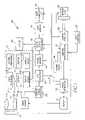
- FIG. 1shows a block diagram of an embodiment of a camera.
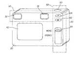
- FIG. 2illustrates one embodiment of a camera of the present invention.
- FIG. 3shows a flow diagram embodiment of a method for using a camera to form a stereo or two-perspective depth image of a scene.
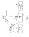
- FIG. 4illustrates the capture of images of a scene from various perspectives and the effect that changing perspectives has on the content of scanning of the scene.
- FIG. 5illustrates the capture of images of a scene from various perspectives.
- FIG. 6illustrates an embodiment of a camera in accordance with the invention.
- FIG. 7illustrates yet another embodiment of a camera in accordance with the invention.
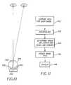
- FIG. 8illustrates one embodiment of a depth viewer in accordance with the invention.
- FIG. 9illustrates the viewing ranges for the content groups associated with one lenticule of FIG. 8 .
- FIG. 10illustrates a depth view having five scan line images associated with a lenticule.
- FIG. 11is a flow diagram of one method for preparing a multi-perspective image for viewing by an observer of a camera.
- FIG. 12illustrates another embodiment of the camera of the present invention.
- FIG. 13shows an illustrative example of a film having metadata encodement.
- FIG. 14shows an embodiment of an image processing apparatus for forming a multi-perspective image having metadata recorded thereon.
- FIG. 1shows a block diagram of an embodiment of a camera 20 .
- camera 20includes a taking lens unit 22 , which directs light from a scene (not shown) to form an image on image sensor 24 .
- the taking lens unit 22can be simple, such as having a single focal length and manual focusing or a fixed focus, but this is not preferred.
- the taking lens unit 22is a motorized 2 x zoom lens unit in which a mobile element or elements 26 are driven, relative to a stationary element or elements 28 by lens driver 30 .
- Lens driver 30controls both the lens focal length and the lens focus position of taking lens unit 22 .
- camera 20has a first viewfinder 32 .
- first viewfinder 32incorporates an electronic display 33 that receives electronically captured and processed images and provides these images to the user of camera 20 so that the user can make decisions regarding the composition of the scene.
- Display 33can comprise, for example, a reflective Liquid Crystal Display (LCD).
- LCDLiquid Crystal Display
- Some examples of reflective LCDs that can be usedare the SXGA-R2-1, SXGA-R2-H1, and/or SXGA-R2-H2 microdisplays sold by CRL Opto Ltd., Dalgety Bay, Dunfermline, Scotland, U.K.
- Display 33can also comprise an organic electroluminescent display (OELD) also known as an organic light emitting display (OLED). Examples of OLED displays useful in this embodiment are the SVGA+ and SVGA 3D displays sold by Emagine Corp. Hopewell Junction, N.Y., U.S.A.
- first viewfinder 32can selectively present images obtained optically from taking lens unit 22 and can also present images that appear on electronic display 33 . This allows a user to look through first viewfinder 32 to observe the scene in an optical viewfinder mode and also allows the user to later observe digitally captured images that are presented using the display.
- display 33can also comprise a transmissive Liquid Crystal Display.
- a transmissive Liquid Crystal Displayis the 640 color display sold by Kopin Corporation, Tauton, Mass., USA.
- a movable mirror 31is selectively placed in the optical path between the eye of an observer and display 33 . In one position, the mirror 31 causes light from taking lens unit 22 to be presented to the eye of an observer.
- mirror 31prevents light from display 33 from traveling to the eye of an observer. This prevents confusion as to what is being observed.
- mirror 31is moved to another position, light from taking lens unit 22 is no longer presented to the eye of the observer, and light from display 33 is presented.
- mirror 31is moved into the optical path.
- the image sensor 24is used to provide multi-spot autofocus using what is called the “through focus” or “whole way scanning” approach.
- the sceneis divided into a grid of regions or spots, and the optimum focus distance is determined for each image region.
- the optimum focus distance for each regionis determined by moving taking lens unit 22 through a range of focus distance positions, from the near focus distance to the infinity position, while capturing images.
- between four and thirty two imagesmay need to be captured at different focus distances.
- capturing images at eight different distancesprovides suitable accuracy.
- the captured image datais then analyzed to determine the optimum focus distance for each image region.
- This analysisbegins by band-pass filtering the sensor signal using one or more filters, as described in commonly assigned U.S. Pat. No. 5,874,994 “Filter Employing Arithmetic Operations for an Electronic Synchronized Digital Cameras” filed by Xie et al., the disclosure of which is herein incorporated by reference.
- the absolute value of the band-pass filter output for each image regionis then peak detected, in order to determine a focus value for that image region, at that focus distance.
- the optimum focus distances for each image regioncan be determined by selecting the captured focus distance that provides the maximum focus value, or by estimating an intermediate distance value, between the two measured captured focus distances which provided the two largest focus values, using various interpolation techniques.
- the lens focus distance to be used to capture the final high-resolution still imagecan now be determined.
- the image regions corresponding to a target objecte.g. a person being photographed
- the focus positionis then set to provide the best focus for these image regions, as described in commonly assigned U.S. Pat. No. 5,877,809 “Method Of Automatic Object Detection In An Image”, filed by Omata et al. on Oct. 15, 1976, the disclosure of which is herein incorporated by reference.
- object trackingmay be performed, as described in commonly assigned U.S. Pat. No. 6,067,114 “Detecting Compositional Change in Image” filed by Omata et al. on Oct.
- the focus values determined by “whole way scanning”are used to set a rough focus position, which is refined using a fine focus mode, as described in commonly assigned U.S. Pat. No. 5,715,483, entitled “Automatic Focusing Apparatus and Method”, filed by Omata et al. on Feb. 3, 1998, the disclosure of which is herein incorporated by reference.
- the band-pass filtering and other calculations used to provide autofocus in camera 20are performed by digital signal processor 40 .
- camera 20uses a specially adapted image sensor 24 , as is shown in commonly assigned U.S. Pat. No 5,668,597, entitled “Electronic Camera With Rapid Autofocus Upon An Interline Image Sensor”, filed by Parulski et al. on Sep. 16, 1997, the disclosure of which is herein incorporated by reference, to automatically set the lens focus position.
- only some of the lines of sensor photoelementsare used to determine the focus. The other lines are eliminated during the sensor readout process. This reduces the sensor readout time, thus shortening the time required to focus taking lens unit 22 .
- camera 20uses a separate optical or other type (e.g. ultrasonic) of range finder 48 to identify the subject of the image and to select a focus position for taking lens unit 22 that is appropriate for the distance to the subject.
- Range finder 48operates lens driver 30 , directly or by camera microprocessor 50 , to move one or more mobile elements 26 of taking lens unit 22 .
- the range finder 48can be passive or active or a combination of the two.
- suitable multiple sensor range finders 48 known to those of skill in the artare suitable for use. For example, U.S. Pat. No. 5,440,369, entitled “Compact Camera With Automatic Focal Length Dependent Adjustments” filed by Tabata et al. on Nov.
- the range finder 48discloses such a range finder 48 .
- a feedback loopis established between lens driver 30 and camera microprocessor 50 so that camera microprocessor 50 can accurately set the focus position of taking lens unit 22 .
- the focus determination provided by the range finder 48can be of the single-spot or multi-spot type.
- the focus determinationuses multiple spots.
- multi-spot focus determinationthe scene is divided into a grid of regions or spots, and the optimum focus distance is determined for each spot and a focus determination is made by identifying the spot or set of spots that are associated with the subject of the image.
- Image sensor 24has a discrete number of photosensitive elements arranged in a two-dimensional array. When the analog signal values from each photosensitive element are digitized by the analog-to digital (A/D) converter 36 , they provide the pixel values of the captured digital image. Thus, each individual photosite on image sensor 24 corresponds to one pixel of the captured digital image, referred to herein as an archival image.
- Image sensor 24can be either a conventional charge coupled device (CCD) sensor or a complementary metal oxide semiconductor image sensor. In one example embodiment, image sensor 24 has an array of 1280 ⁇ 960 photosensitive elements. The photosensitive elements, or photosites, of image sensor 24 convert photons of light from the scene into electron charge packets.
- Each photositeis overlaid with a color filter array, such as the Bayer color filter array described in commonly assigned U.S. Pat. No. 3,971,065, entitled “Color Imaging Array” filed by Boyer on Mar. 5, 1975, the disclosure of which is herein incorporated by reference.
- the Bayer color filter arrayhas 50% green pixels in a checkerboard mosaic, with the remaining pixels alternating between red and blue rows.
- the photositesrespond to the appropriately colored incident light illumination to provide an analog signal corresponding to the intensity of illumination incident on the photosites.
- the analog output of each pixelis amplified and analog processed by an analog signal processor 34 to reduce the output amplifier noise of image sensor 24 .
- the output of the analog signal processor 34is converted to a digital image signal by an A/D converter 36 , such as, for example, a 10-bit bit A/D converter which provides an 10 bit signal in the sequence of the Bayer color filter array.
- the digitized imageis temporarily stored in a frame memory 38 , and is then processed using a programmable digital signal processor 40 as described in commonly assigned U.S. Pat. No. 5,016,107 entitled “Electronic Still Camera Utilizing Image Compression and Digital Storage” filed by Sasson et al. on May 9, 1989, the disclosure of which is herein incorporated by reference.
- the image processingincludes an interpolation algorithm to reconstruct a full resolution color image from the color filter array pixel values using, for example, the methods described in commonly assigned U.S. Pat. No. 5,373,322 entitled “Apparatus and Method for Adaptively Interpolating a Full Color Image Utilizing Chrominance Gradients” filed by LaRoche et al. on Jun. 30, 1993, and U.S. Pat.
- the imagecan be compressed for archival purposes and stored in a data memory 44 .
- the Joint Photographic Experts Group (JPEG) standard specified in ISO 10918-1 (ITUT.81)is used to compress the image for archival storage.
- the compressionuses the well-known discrete cosine transform (DCT) to transform 8 ⁇ 8 blocks of luminance and chrominance signals into the spatial frequency domain. These DCT coefficients are then quantized and entropy coded to produce the JPEG compressed image data.
- This JPEG compressed image datais stored in a file using the so-called “Exif” image format defined in “Digital Still Camera Image File Format (Exif)” version 2.1, July 1998 by the Japan Electronics Industries Development Association Tokyo, Japan.
- the Exif format archival imagecan be stored in a memory card 52 .
- camera 20is shown having a memory card slot 54 which holds a removable memory card 52 and has a memory card interface 56 for communicating with memory card 52 .
- the Exif format archival imagecan also be transmitted to a host computer (not shown), which is connected to camera 20 through a host computer interface 46 .
- the digital signal processor 40also creates a smaller size digital image for display on an image display 42 .
- This imageis referred to herein as a verification image.
- Image display 42can comprise, for example, a color liquid crystal display (LCD), an organic electroluminescent display (OELD) also known as an organic light emitting display (OLED), a cathode ray tube or other type of video display.
- the verification imageis preferably created and displayed immediately after the archival image is captured, and can be created, for example, by conventional down sampling and/or other techniques described in commonly assigned U.S. Pat. No. 5,164,831 “Electronic Still Camera Providing Multi-Format Storage Of Full And Reduced Resolution Images” filed in the name of Kuchta et al. on Mar. 15, 1990, the disclosure of which is herein incorporated by reference.
- This verification imageis stored in data memory 44 and supplied, for example, to image display 42 , which displays the smaller sized, processed verification image for the user to review.
- Camera 20is controlled by user controls 58 , some of which are shown in more detail in FIG. 2 .
- User controls 58include a shutter release 60 which initiates a picture taking operation, along with a “wide” zoom lens button 62 and a “tele” zoom lens button 64 , which in this embodiment together control both a 2:1 optical zoom and a 2:1 digital zoom feature.
- the optical zoomis provided by taking lens unit 22 , and adjusts the magnification in order to change the field of view of the focal plane image captured by the image sensor 24 .
- the digital zoomis provided by the digital signal processor 40 , which crops and resamples the captured image stored in the frame memory 38 .
- the zoom lensis set to the 1:1 position, so that all sensor photoelements are used to provide the captured image, and the taking lens unit 22 is set to the wide angle position.
- this wide angle positionis equivalent to a 40 mm lens on a 35 mm film camera. This corresponds to the maximum wide angle position.
- the taking lens unit 22is adjusted by the camera microprocessor 50 via the lens driver 30 to move the taking lens unit 22 towards a more telephoto focal length. If the user continues to depress the “tele” zoom lens button 64 , the taking lens unit 22 will move to the full optical 2:1 zoom position. In a preferred embodiment, this full telephoto position is equivalent to a 40 mm lens on a 35 mm film camera. If the user continues to depress the “tele” zoom lens button 64 , the taking lens unit 22 will remain in the full optical 2:1 zoom position, and digital signal processor 40 will begin to provide digital zoom, by cropping (and optionally resampling) a central area of the image.
- Image display 42is provided on the back of camera 20 and is sized to permit a user to use the display to interact with camera 20 while holding camera 20 at a convenient viewing distance from the face of the user.
- image display 42will be rectangular in form and on the order of 3.5 cm to 5.1 cm in diagonal measure. However, other shapes and sizes of image display 42 can be used.
- image display 42has a lower imaging resolution than image sensor 24 .
- resolutionis used herein to indicate the number of picture elements used to represent the image.
- displays of the type that are commonly used on digital camerastypically provide 320 ⁇ 240 display elements, which correspond to an image display resolution of about 0.08 megapixels.
- the captured imagecan be derived from a high resolution image sensor 24 , having for example 1280 ⁇ 960 photosites, corresponding to about 1.25 megapixels.
- there are 16 times more sensor elements than display elements and the resolution of a captured imageis 16 times greater than the resolution of image display 42 .
- Camera 20also incorporates a depth viewer 43 .
- Depth viewer 43comprises a display system that is capable of selectively displaying a first verification image to a first viewing area positioned such that the first viewing area can be seen by only one eye of a user and a second verification image to a second viewing area positioned such that the second viewing area can be seen by only another eye of a user.
- depth viewer 43is of a binocular type having separate optical systems comprising a first viewfinder 32 and a second viewfinder 35 .
- second viewfinder 35is adapted with a second display 37 .
- Second display 37can for example comprise an LCD or OLED display or any other form of electronic display that can be conveniently incorporated into camera 20 .
- First display 33 and second display 37are operated by display drivers 39 and 41 respectively.
- Display drivers 39 and 41receive images from digital signal processor 40 and cause first viewfinder 32 and second viewfinder 35 to present one image to a first viewing area confronting one eye of an observer and another image to a second viewing area confronting another eye of the observer.
- the verification images presented by depth viewer 43will have an imaging resolution that is substantially lower than the resolution of the captured images upon which verification images are based. Accordingly, it is necessary to resample the captured image into a verification image having a suitably small image size so that it can be displayed at the image resolution provided by image display 42 or depth viewer 43 .
- This resamplingcan be done by using low pass filtering, followed by sub-sampling, or by using bilinear interpolation techniques with appropriate anti-aliasing conditioning.
- Other techniques known in the art for adapting a high resolution image for display on a relatively low resolution displaycan alternatively be used.
- the resampling of the captured image to produce a verification image having fewer pixels (i.e. lower resolution) than the captured imageis performed by digital signal processor 40 .
- the digital signal processor 40also provides digital zooming. In the maximum 2:1 setting, the digital signal processor 40 uses the central 640 ⁇ 480 sensor area to provide the archival image by interpolating this central area up to 1280 ⁇ 960 samples.
- the digital signal processor 40can also modify the archival image in other ways so that the verification image matches the appearance of the archival image. These include color calibrating the verification image so that when the verification image is presented on the display, the displayed colors of the verification image appear to match the colors in the archival image. These and other modifications help to provide the user with an accurate representation of the color, format, scene content and lighting conditions in the captured image.
- an archival imageis typically captured using image sensor 24 when the user depresses the shutter release 60 .
- a capture sequenceis then initiated by camera microprocessor 50 signaling a timing generator 70 .
- the timing generator 70is connected generally to the elements of camera 20 , as shown in FIG. 1 , for controlling the digital conversion, compression, and storage of the image signal.
- the image sensor 24is driven from the timing generator 70 via a sensor driver 71 to produce the image signal provided to analog signal processor 34 .
- FIG. 3shows a flow diagram of an embodiment of a method for using a camera 20 to form a stereo or two-perspective depth image of a scene 90 shown in FIG. 4 .
- a camera userindicates a desire to record a stereo image—(step 100 ).
- a stream of images of the sceneis presented to one or both of the eyes of the user of camera 20 —(step 102 ). This can be done optically using first viewfinder 32 , second viewfinder 35 , image display 42 , depth viewer 43 or a combination thereof.
- the user of camera 20uses the stream of images to position camera 20 to compose a first image of scene 90 —(step 104 ) for example by adjusting the zoom buttons 62 , 64 while aiming the camera in a desired direction.
- the trigger buttonis then pushed (step 105 ) to indicate a desire to capture an image of the scene.
- the first imageis then captured, for example, when camera 20 is located at position A—(step 106 ).
- the image capturecan, for example, occur in response to the user depression of shutter release 60 .
- the image capturecan also be initiated by camera microprocessor 50 , for example, in response to user programmed delays or time lapses. Prior to capturing the first image, the camera microprocessor 50 can perform an autofocus operation, as described earlier.
- a first image 92is processed as was described earlier, and a verification image based on the first captured image is then presented to only one of the eyes of the user, for example, the user's left eye—(step 108 ).
- the stream of images from the sceneis then presented to the other one of the eyes of the user, for example, the user's right eye. In this way, one eye of the user sees only the first image 92 while the other eye sees the stream of images—(step 110 ).
- the angle of view between camera 20 and scene 90 for the first image 92is different than the angle of view between camera 20 and the scene 90 for the stream of images, parallax induced differences will exist between the first image 92 and the stream of images.
- the operation of the zoom buttons 62 , 64are disabled when previewing and capturing the second image, so that the same zoom setting is used to capture the first and second images. Further, the autofocus operation is performed only when capturing the first image, and the focus is locked when capturing the second image, so that the focus distance is the same for both images.
- first image 92 and second image 94contain the same scene elements, but have different appearances because of the difference in viewing angle. This allows the user to review the appearance of the pair of images 92 and 94 image in stereo—(step 120 ) and to determine whether the stereo image pair has an acceptable appearance—(step 122 ).
- the user of camera 20can discard the second image 94 and capture a new second image.
- the processreturns to displaying the first image to one eye of the user (step 110 ) while presenting a live preview of the scene to the other eye of the observer (step 110 ) in order to compose a second image—(step 112 ).
- Thisallows the user to recompose the second image of the scene to modify the apparent depth, and to create a new image incorporating, for example, first image 92 and a third image 96 captured with camera 20 at point C in FIG. 4 .
- First image 92 and third image 96are then stored as an archival image pair from which a stereoscopic depth image can be rendered.
- the selected archival image paircan be further processed—(step 124 ). Such further processing can comprise digital manipulation and storage of the images.
- the selected archival image pair 92 and 96are further processed by forming a differential image that represents the differences between the first archival image and the second archival image—(step 126 ). This can be done, for example, by subtracting the pixel values of third image 96 from the pixel values of the first image 92 .
- the advantage of this approachis that the differential image can normally be compressed to be much smaller in size than one of the compressed archival images. Further, the differential image can be used to locate areas in the archival images having significant stereoscopic depth.
- the differential imageis stored along with the first archival image in a single image file.
- the differential image informationcan be stored within one or more application segments in a JPEG file containing the first image (or alternatively the second image) in accordance with the JPEG standard format ISO 10918-1 (ITU—T.81) (Step 128 ).
- ISO 10918-1ISO 10918-1
- This approachfurther allows the stored first image to be used, processed, and displayed using software and equipment which support the present standard JPEG images while still permitting the first image and associated differential image data stored in the application segment to be used for creating a multi-perspective image by software and equipment adapted for such a purpose.
- the selected archival image paircan be stored as two separate standard image files, in either compressed or uncompressed form. Metadata can be encoded with each image, for example, using a JPEG application segment associated with each of the JPEG images with the metadata indicating that the images are to be incorporated into a multi-perspective image.
- the archival image paircan be stored as first and second images in the same non-standard image file. The two images 92 and 96 can then be extracted from the file in a manner that separates imaging information that is to be presented to one eye of the user from imaging information that is to be presented to the other eye of the user.
- archival image paircan be further processed to form a single composite image file so that they can be presented together using an appropriate display.
- this composite imageis displayed using a depth image display, which uses lenticular, micro-lens or barrier type optical systems to present slightly different scene information to each of the viewer's eyes as will be described later.
- Multi-Perspective ImagingLook Around Image
- depth images having a look around effectcan be formed by positioning a camera 20 to capture a series of views from different perspectives. As illustrated, several perspective images of scene 90 from different viewpoints are captured as a first view series by positioning camera 20 at, for example, positions D, E, F, G and H arranged along a capture axis 93 . Any number of positions greater than two can be used to form a depth image having a look around effect. Each additional image can be used to increase the extent of the overall look around effect.
- FIG. 6illustrates an embodiment of camera 20 having a look around position control 123 that allows the user to select the number of images n to be incorporated in a series of images that are used to form a depth image. This allows a particular number of separate perspective images to be captured in an image capture mode.
- the number of images n in the series of images to be capturedis detected.
- a first image paircomprising a first archival image and a second archival image is then composed and captured using the method described for forming a stereo image as described above with respect to FIG. 3 .
- Subsequent images in the sequenceare composed by presenting one eye of the user of camera 20 with a verification image of the last captured archival image and another eye of the user with a stream of images of the scene and capturing additional images based upon imaging information from the last captured image and the stream of captured images.
- the sequence of imagesis then presented in pairs of sequential verification images to the user of camera 20 using depth viewer 43 .
- a set of five imagesis captured from positions D, E, F, G and H.
- Thisprovides four depth views of scene 90 and therefore provides look around capability.
- imaging information from images captured at positions D and Eis used to generate a depth image.
- imaging information from images captured at positions E and Fare used to generate a second depth view of scene 90
- imaging information from images captured at positions F and Gare used to generate a view 3 of scene 90
- imaging information from images captured at positions G and Hare used to generate view 4 of scene 90 .
- the camera positions D, E, F and Gare separated by the same distance. Accordingly, the change in perspective observed in the look around effect generated as a viewer transitions from the first depth view of scene 90 to the second depth view of scene 90 to the third depth view of scene 90 will appear to be constant. However, as is also shown in FIG. 5 , the separation between positions G and H is greater than the distance that separates positions D, E, F and G. Because of this, the change in apparent perspective observed as the viewer transitions from view 3 of the scene to view 4 of the scene will not appear to be constant. This provides the photographer with greater creative control in the formation of a look around image.
- Camera 20 and depth viewer 43are adapted to allow the user of camera 20 to simulate an angle of view so that particular pairs of verification images can be examined in context with other pairs of verification images.
- user controls 58include a look around position control 123 .
- Look around position control 123provides an input to camera microprocessor 50 that causes selected ones of the set of depth views to appear in sequence on depth viewer 43 .
- depth viewer 43will display imaging information from a selected view of the scene such as view 1 .
- view 4incorporates imaging information from images captured, for example, at positions F and G.
- a user of camera 20can modify the position of look around position control 123 to cause depth viewer 43 to selectively display imaging information from other views using depth viewer 43 . This permits the photographer to review each view and to make decisions regarding whether to replace imaging information captured, for example, from position G with imaging information captured at, for example, position G′ shown in FIG. 5 .
- FIG. 7shows another embodiment of camera 20 of the present invention having a non-binocular depth viewer 43 .
- An example of such a combinationis described in commonly assigned U.S. Pat. No. 5,715,383 entitled “Compound Depth Image Display System” filed by Schindler et al. on Sep. 28, 1992.
- FIGS. 8 and 9illustrate the operation of this depth viewer.
- depth viewer 43comprises a display 200 and a depth image projection device 208 .
- display 200generally has a flat display surface 210 on which images are formed.
- Display 200can comprise, for example, an active matrix liquid crystal display or an organic light emitting display, or conventional cathode ray tube display.
- the images formed on flat display surface 210are viewed through a depth image projection device 208 such as a lenticular screen 212 comprising a plurality of lenticules 270 attached to the flat display surface 210 .
- lenticules 274comprise a set of hemi-cylindrical lenses shown in cross-section in FIG. 8 .
- lenticules 270can comprise any useful optical element that causes the effects to be described herein with reference to FIG. 8 , including but not limited to hemi-spherical lenses, hemi-aspherical or hemi-acylindrical lenses.
- Flat display surface 210 and depth image projection device 208can be integrally related such that, for example, the depth image projection device 208 could be formed on one side of the glass of the display 200 .
- a viewer observing the image from the particular angle of view point 220sees imaging information formed from area X of the image.
- a viewer observing the scene from view point 230sees imaging information from area Y of the image.
- a viewer observing the image from view point 240sees imaging information from area Z of the image. This effect can be used to present different imaging information to the two eyes of an observer.
- the left eye of an observeris located at view point 220 while the right eye of an observer is located at view point 230 , the left eye will see that portion of the display image that is located in area X of the displayed image while the right eye of the observer, looking at the same image on the same screen will see image Y.
- depth viewer 43can be used to present an image of first view 202 of a scene in area X and a second view of the same scene taken from a different perspective than the perspective of the first view in area Y.
- first angle of view 202with his left eye at view point 220 and his right eye at view point 230 the observer will be able to detect parallax induced differences between the first image and the second image.
- the mind of the observercan interpret these differences as depth in an image. This achieves a stereoscopic depth effect.
- Look around effectscan be created by using a look around position control 123 in the manner described above with respect to the binocular embodiment of depth viewer 43 .
- a look around depth effectcan also be created using flat display surface 210 . That is, the image presented to the observer would look as if it was a three dimensional object that would have different characteristics depending upon the angle of view relative to the screen. This is done, in the example shown in FIG. 8 , by displaying imaging information from a third image on area Z of flat display surface 210 . This effect becomes noticeable when a viewer whose eyes are located at view points 220 and 230 changes perspective relative to the image to a second angle of view 204 wherein his left eye is moved to view point 230 and his right eye is positioned at view point 240 . This causes the mind of the observer to see a version of the scene that incorporates only the imaging information from the second and third images.
- the appearance of the scene as observed at the first angle of first view 202has imaging information that is not apparent from second angle of view 204 .
- the viewercan effectively look around the scene simply by changing the viewing angle with respect to the depth viewer 43 .
- Adding additional images in other areas behind each lenticule 274 of lenticular screen 212allows the observer to see additional view points by changing her angular perspective with respect to the depth viewer 43 .
- a slightly different image of the same content from a different perspectivemust be presented to each eye of the viewer and when the viewer changes position within the range of view points suitable for viewing the particular depth image. Additional information concerning how depth images are created and recorded can be found in the related applications previously mentioned and the theory behind depth or three dimensional images can be obtained from Three-Dimensional Imaging Techniques, Okoshi, Academic Press, New York, 1976.
- the images that correspond to a particular content and thus to a particular view pointare called a content group.
- each of the lenticular scan line imagespresents to the viewer a different slice or portion of a view of the same content, thereby allowing depth to be perceived.
- FIG. 8shows three lenticular sets, 260 , 262 and 264 .
- the image that is seen from view point 220is composed of a group of scan line images 222 , 224 and 226 each associated with different lenticules 270 , 272 and 274 and projected to the viewer by the lenticular screen 212 .
- the position of the group of content imagesis different for each lenticule with respect to what could be called the optical axis 276 , 278 and 280 of each lenticule.
- the content group containing scan line image 222 from view point 220is arranged directly under the optical axis 276 of lenticule 270 while the same content group has a scan line image 226 for lenticule 274 that is displaced to the left with respect to the optical axis 280 of that lenticule 274 .
- the displacementinstead of moving in a single direction as occurs with respect to view point 220 , moves in both directions on both sides of the center of the display.
- the content group that includes scan line image 236is observable from view point 230 .
- scan line image 236is displaced to the left of the optical axis 280 of the lenticule 274 while the scan line image 234 is displaced to the right of the optical axis 276 of lenticule 270 .
- the image content group for each view pointis displaced differently depending on the location of the view point and the relative location of the lenticule projecting its slice of the view to the view point.
- the spacing between lenticular sets or displacement of the center of each set with respect to the corresponding optical axisalso varies across the substrate where the spacing or displacement increases as the projecting lenticule moves out from the center of the depth viewer 43 . That is, not only must the intergroup spacing or displacement be adjusted to account for the viewpoint but the interlenticule set spacing or displacement must also account for the different viewpoints.
- a lenticular screen 212 having 53 lenticules per inchit is possible to create 24 separate scan line images which correspond to a particular lenticule. That is, 24 different images can be presented to the viewer depending upon the view point of the viewer.
- each lenticulewould project a different scan line or image slice to a different view point and the viewers eye/brain integrates all the slices into a single picture or image.
- a depth imageis desired, at least two images must be used to provide a different perspective for each eye when viewing the content from that particular view point.
- 12 different view pointsproviding 12 depth images in a compound document for the typical lenticular screen.
- a much higher quality depth imageis provided when at least four different images are used to create each content group, thereby allowing up to six view points from which a depth image can be provided over a small range of viewing angles.
- the content documentpreferably has three view points allowing eight different images to be perceived from a range around a particular view point thereby providing a much better sense of depth for each of the depth images.
- the spacing or changes in displacement of the groups and sets of imagescan be accomplished in accordance with the procedures described in more detail in the cross-referenced applications.
- FIG. 9illustrates the viewing area for the content groups associated with lenticule 274 of FIG. 8 .
- the edges of each of the scan line images 226 , 236 and 242define the outer edges of the viewing area for each of the scan line images.
- the viewing areachanges depending upon the angle with respect to the lenticule 274 .
- the viewing area 294 for images from lenticule 274 from view point 220is a larger area than the viewing area 290 for the content group 242 for view point 220 and it is thus useful to restrict the viewing area to the minimum viewing range provided for each view point which will be the view point directly over the center image group aligned with the view point.
- the minimum viewing area for viewpoint 240is defined by scan line image 242 and lenticule 274 .
- FIG. 10shows another example from the '383 patent having five scan line images 302 associated with lenticule 374 having an optical axis 380 .
- the eyes of the viewerperceive different ones of the scan lines, thereby providing the viewer with a sense of depth if each of the scan lines is from a different perspective of an originally captured scene.
- multiple scan lines for each groupsuch as the five scan lines as illustrated in FIG. 10
- view point 240different scan lines will be presented by each lenticule from a slightly different perspective, thereby preserving the stereoscopic or depth image effect and allowing the viewer a limited “look around” capability with respect to the content being viewed at each view point.
- the scan line spacing associated with each of the lenticular scan line image 302is adjusted with a different spacing therebetween depending upon the viewing angle for that particular lenticule. This scan line spacing adjustment is described in the related applications previously mentioned.
- one of the “look around” viewscan include text overlaying the image.
- the textcan include the date and time the image was captured, the camera settings (e.g. shutter speed, f/#), and/or text describing the image entered by the user via user controls 58 or a voice recognition system included in the camera 20 (not shown).
- the textcan be rendered in 3-dimensions, and can be displayed at a depth that best separates it from the scene. In such embodiments, the text from one position is visible when the viewer looks at one of the views, and is not visible in other views.
- FIG. 11illustrates the procedure described in the '383 patent and used in one embodiment of the present invention to form images for presentation using a depth viewer 43 having depth image projection device 208 .
- the first stepis to capture the views for each image which will be presented within the multi-perspective image—(step 410 ). As previously mentioned, this capture and storage of the particular depth images is performed in the manner described above.
- the optional step of generating additional images based upon the captured imagescan be performed. This can be done, for example, by using interpolation (step 412 ) to create new images as described in the related applications.
- the desired view pointsare used to determine (step 414 ) the set spacing for each lenticule, the image content group spacing or the spacing between groups and the order of that spacing, and the scan line spacing within each image.
- the view pointscan be determined based upon the assumption that the camera will be held in the hand when the depth image is viewed.
- these spacingscan be predefined with imaging information from the set of images being adapted and used to derive content groups having this fixed spacing.
- the imaging file for imaging the scan line images with the spacings desiredis created (step 416 ) by sorting the scan lines with included spacing or positions into the order that they will be scanned during imaging.
- the controller of camera 20 and/or the digital signal processor 40can dynamically establish the spacings and positions of the scan line images.
- an image demarcation linesuch as a black line
- This linewill cause the viewer to perceive that the entire compound image has turned dark as the viewer moves from one view point to the next view point. As the viewer moves past the edge of the acceptable viewing range the image will darken, detracting from the viewability of the image and thereby encouraging the viewer to move back to the acceptable areas.
- This demarcation lineis created by filling in the intergroup gap, such as gap 266 shown in FIG. 8 , with a black mask
- the content group viewable from different view pointsis defined such that all of the images presented to the viewer at that view point are of the same content. It is possible for that particular view point to create “ghost” images viewable within the content for that view point. For example, it is possible to present a ghost image containing text that appears overlayed or mixed in with the scan lines for each content group. Of course this could be a depth image allowing depth ghost text images within depth primary images.
- the spacings between or displacements of sets, content groups and scan lineshas been described as continuously variable across the image responsive to the view point. It is possible to determine a compromise constant spacing which works well for all the desired view points and use that to fix the particular positions of the scan lines.
- the images from different view pointsare depth images of a stationary scene.
- one or more of the imagesto be non depth images of a moving scene with the angularly changing image information being used for example to allow a photographer to cycle through a set of related images such as a set of images captured using a “motion burst” mode.
- the descriptionalso indicates that the spacing of the groups, etc. is determined each time a multi-perspective image is produced. It is possible to standardize the arrangement and spacing of the images and to produce a map that designates where each scan line is to be located for a particular type of multi-perspective image. This may be preferable in order to simplify the calculations performed by digital signal processor 40 in digital camera 20 .
- depth viewer 43can also be used to provide conventional preview and other imaging functions. Where this is done, for example, in the embodiments shown in FIGS. 7-11 , the lenticular or other depth display device can be caused to present the same imaging information in areas A, B and C of the display. Because there are no parallax induced differences in the images observed by the viewer, an image that is so presented will have a conventional two dimensional appearance. In this mode the lenticular screen 212 serves to widen the effective field of view of the depth viewer 43 for preview sharing purposes.
- one embodiment of camera 304can include a second image capture system 130 such as a film image capture system.
- a second image capture system 130such as a film image capture system.
- metadatacan be stored in association with the film that indicates which of the images on the film are to be incorporated into a multi-perspective image and in which order.
- This metadatacan be stored, for example, on a strip of magnetic material, or on an optical form on the film.
- the metadatacan also be stored on an electronic memory that is associated with the film.
- the metadatacan, for example, be recorded using a binary or other machine readable code.
- the metadatacan be recorded in formatted blocks with each block having a start sentinel, metadata and an end sentinel. For redundancy, multiple copies of each block can be recorded.
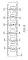
- FIG. 13shows an illustrative example of a film 300 having such a metadata encodement.
- film 300has six images recorded thereon.
- archival image 310represents an archival image of scene 90 of FIG. 5 that is recorded at position D of FIG. 5 .
- image 312 recorded at position E of FIG. 5image 314 is an image that is recorded at position F of FIG. 5
- image 316 recorded at position G of FIG. 5image 318 recorded at position H shown in FIG. 5
- additional image 320 recorded at position G′ shown in FIG. 5is an image that is recorded at position F of FIG. 5 .
- image 316recorded at position G of FIG. 5
- image 318 recorded at position H shown in FIG. 5and additional image 320 recorded at position G′ shown in FIG. 5 .
- Metadata elements 322 , 324 , 326 , 328 , 330 and 332are associated with, respectively, images 310 , 312 , 314 , 316 , 318 and 320 .
- This metadataindicates that the image is to be included in a multi-perspective image and the context that the image is to be used in association with.
- the photographerhas reviewed view 4 shown in FIG. 5 which combines images 316 and 318 and determined that she does not like the view. Accordingly the photographer uses user controls 58 to indicate to camera microprocessor 50 that image 318 is not to be included in the depth image.
- metadata elements 322 - 332are optically recorded on film 300 in association with image 318 indicating that the image is not to be used.
- An additional image 320is captured and metadata element 332 is associated with additional image 320 indicating that additional image 320 is to be combined with image 316 to form a revised view 4 .
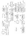
- FIG. 14shows an embodiment of an image processing apparatus 500 for forming a multi-perspective image using a film 502 having a multi-perspective image and metadata recorded thereon.
- a camera 504records images on film 300 .
- Film 300is extracted from camera 504 and processed.
- the processed film 300is then provided to apparatus 500 .
- a metadata detector 540detects the recorded metadata and generates a signal which is received by scanner controller 545 .
- detector 540examines the magnetic signals on the images on the film to detect the metadata elements 522 - 532 .
- Scanner controller 545receives these metadata elements and extracts useful information from the metadata elements including information indicating that images 310 , 312 , 314 , and 316 are to be incorporated in a multi-perspective image.
- Each of images 310 , 312 , 314 and 316are then scanned using optical system 540 , which includes a film illumination system a scanner lens, and scanner image sensor 544 , and converted into a digital form by analog to digital converter 546 .
- the digital image files representing images 310 , 312 , 314 and 316are then provided to digital signal processor 548 .
- detector 540When detector 540 detects metadata element 330 , detector 540 sends a signal to scanner controller 545 indicating that image 318 is not to be included in the multi-perspective image. Scanner controller 545 then omits the process of scanning image 318 and to proceeds to scan additional image 320 . Additional image 320 is then scanned and converted into digital form. The digital form of additional image 320 is then provided to digital signal processor 548 which incorporates additional image 320 as a final image in a series of images including image 310 , 312 , 314 , 316 and 320 in sequence. A multi-perspective image is then formed by digital signal processor 548 .
- the multi-perspective imagecan be electronically transmitted to a remote location or written to a variety of output devices as shown in FIG. 14 including, but not limited to, photosensitive element recorder 358 , which records images on a photosensitive element 356 .
- the multi-perspective imagecan also be recorded on a print media 572 such as a paper or film using for example a printer 574 which can be a thermal printer, electrophotographic printer, ink-jet or other form of printer.
- a recorded multi-perspective imagecan then be joined to a depth image projection device such as a lenticular screen to form a depth image.
- Digital data representing the multi-perspective imagecan be stored in, for example, CD or DVD disks 568 using an optical drive 570 , magnetic electronic signal storage disks 564 by way of a magnetic drive 566 , and other types of storage devices 550 and display devices 552 known in the art.
- a network interface 554is also shown in FIG. 14 . This interface permits captured multi-perspective images to be transmitted by way of a telecommunications network 355 to a multi-perspective image photofinisher 557 for professional quality photofinishing. Multi-perspective images can also be provided by digital camera 20 connected using docking station 542 .
- depth image projection device 208has been described as a lenticular screen.
- depth image projection device 208can comprise an optical barrier such as is described in the '383 patent which blocks a first portion of light from a display from one eye of an observer while blocking a second portion of light from a display from the other eye of the observer.
Landscapes
- Engineering & Computer Science (AREA)
- Multimedia (AREA)
- Signal Processing (AREA)
- Physics & Mathematics (AREA)
- General Physics & Mathematics (AREA)
- Studio Devices (AREA)
Abstract
Description
- 20 camera
- 22 taking lens unit
- 24 image sensor
- 26 mobile elements
- 28 stationary elements
- 29 mirror
- 30 lens driver
- 32 first viewfinder
- 31 mirror
- 33 first display
- 34 analog signal processor
- 35 second viewfinder
- 36 A/D converter
- 37 second display
- 38 frame memory
- 39 display driver
- 40 digital signal processor
- 41 display driver
- 42 image display
- 43 depth viewer
- 44 data memory
- 46 host computer interface
- 48 range finder
- 50 camera microprocessor
- 52 removable memory card
- 54 memory card slot
- 56 memory card interface
- 58 user controls
- 60 shutter release
- 62 wide zoom lens button
- 64 tele zoom lens button
- 66 shutter
- 70 timing generator
- 71 sensor driver
- 90 scene
- 92 first image
- 93 capture axis
- 94 second image
- 96 third image
- 100 select stereo step
- 102 present live preview step
- 104 compose image step
- 105 press trigger step
- 106 capture first image step
- 108 present first image step
- 110 present live preview step
- 112 compose second image step
- 114 press trigger step
- 116 capture next image step
- 118 present second image step
- 120 review stereo pair step
- 122 accept step
- 123 look around position control
- 124 further process step
- 126 form differential image step
- 128 store difference image step
- 130 render output step
- 130 second image capture system
- 200 display
- 202 first view
- 208 depth image projection device
- 210 flat display surface
- 212 lenticular screen
- 220 view point
- 222 scan line image
- 224 scan line image
- 226 scan line image
- 230 view point
- 232 scan line image
- 234 scan line image
- 236 scan line image
- 240 view point
- 242 scan line image
- 250 first angle view
- 260 lenticular set
- 262 lenticular set
- 264 lenticular set
- 266 gap
- 270 lenticule
- 272 lenticule
- 274 lenticule
- 276 optical axis
- 278 optical axis
- 280 optical axis
- 290 viewing area
- 292 viewing area
- 294 viewing area
- 300 film
- 302 scan line image
- 310 image
- 312 image
- 314 image
- 316 image
- 318 image
- 320 additional image
- 322 metadata elements
- 324 metadata elements
- 326 metadata elements
- 328 metadata elements
- 330 metadata elements
- 331 image processing apparatus
- 332 metadata elements
- 374 lenticule
- 380 optical axis
- 410 capture view step
- 412 interpolate step
- 414 determine step
- 416 order step
- 418 display step
- 504 camera
- 540 optical system
- 542 content group
- 544 scanner image sensor
- 545 scanner controller
- 546 digital converter
- 548 signal processor
- 550 storage device
- 552 display devices
- 555 network
- 556 photosensitive element
- 557 multi-perspective image photofinisher
- 558 image recorder
- 564 storage disks
- 566 magnetic drive
- 568 DVD disk
- 570 optical drive
- 572 print media
- A imaging position
- B imaging position
- C imaging position
- D imaging position
- E imaging position
- F imaging position
- G imaging position
- G′ imaging position
- H imaging position
- X area
- Y area
- Z area
Claims (26)
Priority Applications (1)
| Application Number | Priority Date | Filing Date | Title |
|---|---|---|---|
| US10/235,524US7466336B2 (en) | 2002-09-05 | 2002-09-05 | Camera and method for composing multi-perspective images |
Applications Claiming Priority (1)
| Application Number | Priority Date | Filing Date | Title |
|---|---|---|---|
| US10/235,524US7466336B2 (en) | 2002-09-05 | 2002-09-05 | Camera and method for composing multi-perspective images |
Publications (2)
| Publication Number | Publication Date |
|---|---|
| US20040046885A1 US20040046885A1 (en) | 2004-03-11 |
| US7466336B2true US7466336B2 (en) | 2008-12-16 |
Family
ID=31990522
Family Applications (1)
| Application Number | Title | Priority Date | Filing Date |
|---|---|---|---|
| US10/235,524Expired - Fee RelatedUS7466336B2 (en) | 2002-09-05 | 2002-09-05 | Camera and method for composing multi-perspective images |
Country Status (1)
| Country | Link |
|---|---|
| US (1) | US7466336B2 (en) |
Cited By (37)
| Publication number | Priority date | Publication date | Assignee | Title |
|---|---|---|---|---|
| US20060082644A1 (en)* | 2004-10-14 | 2006-04-20 | Hidetoshi Tsubaki | Image processing apparatus and image processing program for multi-viewpoint image |
| US20060221072A1 (en)* | 2005-02-11 | 2006-10-05 | Se Shuen Y S | 3D imaging system |
| US20070076016A1 (en)* | 2005-10-04 | 2007-04-05 | Microsoft Corporation | Photographing big things |
| US20070076920A1 (en)* | 2005-10-04 | 2007-04-05 | Microsoft Corporation | Street side maps and paths |
| US20070165129A1 (en)* | 2003-09-04 | 2007-07-19 | Lyndon Hill | Method of and apparatus for selecting a stereoscopic pair of images |
| US20070252674A1 (en)* | 2004-06-30 | 2007-11-01 | Joakim Nelson | Face Image Correction |
| US20080002879A1 (en)* | 2006-06-29 | 2008-01-03 | Sungkyunkwan University Foundation For Corporate Collaboration | Rectification system and method of stereo image in real-time |
| US20080129728A1 (en)* | 2006-12-01 | 2008-06-05 | Fujifilm Corporation | Image file creation device, imaging apparatus and file structure |
| US20080174658A1 (en)* | 2007-01-23 | 2008-07-24 | Santus David E | High speed photography system for producing 3D still pictures and movies |
| US20080298693A1 (en)* | 2007-05-31 | 2008-12-04 | Arun Hampapur | Method, system, and program product for presenting electronic surveillance data |
| US20090160931A1 (en)* | 2007-12-20 | 2009-06-25 | Nokia Corporation | Image processing for supporting a stereoscopic presentation |
| US20090201363A1 (en)* | 2006-07-24 | 2009-08-13 | Seefront Gmbh | Autostereoscopic system |
| US20100220220A1 (en)* | 2003-12-15 | 2010-09-02 | Myoung-Hoon Park | Method of controlling digital photographing apparatus |
| US20110007155A1 (en)* | 2009-07-07 | 2011-01-13 | Smc Kabushiki Kaisha | Position measurement apparatus and position measuring method |
| US20110025829A1 (en)* | 2009-07-31 | 2011-02-03 | 3Dmedia Corporation | Methods, systems, and computer-readable storage media for selecting image capture positions to generate three-dimensional (3d) images |
| US20110187829A1 (en)* | 2010-02-01 | 2011-08-04 | Casio Computer Co., Ltd. | Image capture apparatus, image capture method and computer readable medium |
| US20110228043A1 (en)* | 2010-03-18 | 2011-09-22 | Tomonori Masuda | Imaging apparatus and control method therefor, and 3d information obtaining system |
| US20110304697A1 (en)* | 2010-06-14 | 2011-12-15 | Lg Electronics Inc. | Electronic device and control method thereof |
| US8213749B2 (en) | 2000-10-06 | 2012-07-03 | Verderi, LLC | System and method for creating, storing and utilizing images of a geographic location |
| WO2012094220A1 (en) | 2011-01-03 | 2012-07-12 | Eastman Kodak Company | Producing stereoscopic image |
| US8274552B2 (en) | 2010-12-27 | 2012-09-25 | 3Dmedia Corporation | Primary and auxiliary image capture devices for image processing and related methods |
| WO2012158446A1 (en) | 2011-05-13 | 2012-11-22 | Eastman Kodak Company | Stereoscopic camera using anaglyphic display for guiding the image capture |
| US20120293632A1 (en)* | 2009-06-09 | 2012-11-22 | Bartholomew Garibaldi Yukich | Systems and methods for creating three-dimensional image media |
| US8508580B2 (en) | 2009-07-31 | 2013-08-13 | 3Dmedia Corporation | Methods, systems, and computer-readable storage media for creating three-dimensional (3D) images of a scene |
| US9185388B2 (en) | 2010-11-03 | 2015-11-10 | 3Dmedia Corporation | Methods, systems, and computer program products for creating three-dimensional video sequences |
| US20150381899A1 (en)* | 2014-06-30 | 2015-12-31 | Casio Computer Co., Ltd. | Image processing apparatus and image processing method for synthesizing plurality of images |
| US9344701B2 (en) | 2010-07-23 | 2016-05-17 | 3Dmedia Corporation | Methods, systems, and computer-readable storage media for identifying a rough depth map in a scene and for determining a stereo-base distance for three-dimensional (3D) content creation |
| US9380292B2 (en) | 2009-07-31 | 2016-06-28 | 3Dmedia Corporation | Methods, systems, and computer-readable storage media for generating three-dimensional (3D) images of a scene |
| US9524021B2 (en) | 2012-01-05 | 2016-12-20 | California Institute Of Technology | Imaging surround system for touch-free display control |
| US9530213B2 (en) | 2013-01-02 | 2016-12-27 | California Institute Of Technology | Single-sensor system for extracting depth information from image blur |
| US9635348B2 (en)* | 2009-07-31 | 2017-04-25 | 3D Media Corporation | Methods, systems, and computer-readable storage media for selecting image capture positions to generate three-dimensional images |
| US10200671B2 (en) | 2010-12-27 | 2019-02-05 | 3Dmedia Corporation | Primary and auxiliary image capture devices for image processing and related methods |
| US11016579B2 (en) | 2006-12-28 | 2021-05-25 | D3D Technologies, Inc. | Method and apparatus for 3D viewing of images on a head display unit |
| US11228753B1 (en) | 2006-12-28 | 2022-01-18 | Robert Edwin Douglas | Method and apparatus for performing stereoscopic zooming on a head display unit |
| US11275242B1 (en) | 2006-12-28 | 2022-03-15 | Tipping Point Medical Images, Llc | Method and apparatus for performing stereoscopic rotation of a volume on a head display unit |
| US11315307B1 (en) | 2006-12-28 | 2022-04-26 | Tipping Point Medical Images, Llc | Method and apparatus for performing rotating viewpoints using a head display unit |
| US11533464B2 (en) | 2018-08-21 | 2022-12-20 | Samsung Electronics Co., Ltd. | Method for synthesizing intermediate view of light field, system for synthesizing intermediate view of light field, and method for compressing light field |
Families Citing this family (76)
| Publication number | Priority date | Publication date | Assignee | Title |
|---|---|---|---|---|
| US7154157B2 (en)* | 2002-12-30 | 2006-12-26 | Intel Corporation | Stacked semiconductor radiation sensors having color component and infrared sensing capability |
| JP2005295004A (en)* | 2004-03-31 | 2005-10-20 | Sanyo Electric Co Ltd | Stereoscopic image processing method and apparatus thereof |
| US20050286719A1 (en)* | 2004-06-29 | 2005-12-29 | Canon Kabushiki Kaisha | Generating entropy through image capture |
| DE102004049163B3 (en)* | 2004-10-08 | 2005-12-29 | Siemens Ag | Method for determining a complete depth information of a camera image |
| KR100706676B1 (en)* | 2004-12-13 | 2007-04-11 | 엘지.필립스 엘시디 주식회사 | Mobile terminal with folding liquid crystal display screen |
| US9489717B2 (en)* | 2005-01-31 | 2016-11-08 | Invention Science Fund I, Llc | Shared image device |
| US20060173972A1 (en)* | 2005-01-31 | 2006-08-03 | Searete Llc, A Limited Liability Corporation Of The State Of Delaware | Audio sharing |
| US20060187230A1 (en)* | 2005-01-31 | 2006-08-24 | Searete Llc | Peripheral shared image device sharing |
| US20060285150A1 (en)* | 2005-01-31 | 2006-12-21 | Searete Llc, A Limited Liability Corporation Of The State Of Delaware | Regional proximity for shared image device(s) |
| US20060221197A1 (en)* | 2005-03-30 | 2006-10-05 | Jung Edward K | Image transformation estimator of an imaging device |
| US8902320B2 (en)* | 2005-01-31 | 2014-12-02 | The Invention Science Fund I, Llc | Shared image device synchronization or designation |
| US7920169B2 (en)* | 2005-01-31 | 2011-04-05 | Invention Science Fund I, Llc | Proximity of shared image devices |
| US8606383B2 (en) | 2005-01-31 | 2013-12-10 | The Invention Science Fund I, Llc | Audio sharing |
| US9325781B2 (en) | 2005-01-31 | 2016-04-26 | Invention Science Fund I, Llc | Audio sharing |
| US20060190968A1 (en)* | 2005-01-31 | 2006-08-24 | Searete Llc, A Limited Corporation Of The State Of The State Of Delaware | Sharing between shared audio devices |
| US9124729B2 (en)* | 2005-01-31 | 2015-09-01 | The Invention Science Fund I, Llc | Shared image device synchronization or designation |
| US7876357B2 (en)* | 2005-01-31 | 2011-01-25 | The Invention Science Fund I, Llc | Estimating shared image device operational capabilities or resources |
| US9910341B2 (en) | 2005-01-31 | 2018-03-06 | The Invention Science Fund I, Llc | Shared image device designation |
| US20060170956A1 (en)* | 2005-01-31 | 2006-08-03 | Jung Edward K | Shared image devices |
| US20060174203A1 (en)* | 2005-01-31 | 2006-08-03 | Searete Llc, A Limited Liability Corporation Of The State Of Delaware | Viewfinder for shared image device |
| US20060187227A1 (en)* | 2005-01-31 | 2006-08-24 | Jung Edward K | Storage aspects for imaging device |
| US9082456B2 (en) | 2005-01-31 | 2015-07-14 | The Invention Science Fund I Llc | Shared image device designation |
| TWI276904B (en)* | 2005-02-01 | 2007-03-21 | Avermedia Tech Inc | A document camera and its digital image zoom system |
| US9819490B2 (en) | 2005-05-04 | 2017-11-14 | Invention Science Fund I, Llc | Regional proximity for shared image device(s) |
| US9942511B2 (en) | 2005-10-31 | 2018-04-10 | Invention Science Fund I, Llc | Preservation/degradation of video/audio aspects of a data stream |
| US9967424B2 (en)* | 2005-06-02 | 2018-05-08 | Invention Science Fund I, Llc | Data storage usage protocol |
| US20070008326A1 (en)* | 2005-06-02 | 2007-01-11 | Searete Llc, A Limited Liability Corporation Of The State Of Delaware | Dual mode image capture technique |
| US10003762B2 (en) | 2005-04-26 | 2018-06-19 | Invention Science Fund I, Llc | Shared image devices |
| US20070109411A1 (en)* | 2005-06-02 | 2007-05-17 | Searete Llc, A Limited Liability Corporation Of The State Of Delaware | Composite image selectivity |
| US9451200B2 (en)* | 2005-06-02 | 2016-09-20 | Invention Science Fund I, Llc | Storage access technique for captured data |
| US20070222865A1 (en)* | 2006-03-15 | 2007-09-27 | Searete Llc, A Limited Liability Corporation Of The State Of Delaware | Enhanced video/still image correlation |
| US8681225B2 (en)* | 2005-06-02 | 2014-03-25 | Royce A. Levien | Storage access technique for captured data |
| US9001215B2 (en)* | 2005-06-02 | 2015-04-07 | The Invention Science Fund I, Llc | Estimating shared image device operational capabilities or resources |
| US7782365B2 (en)* | 2005-06-02 | 2010-08-24 | Searete Llc | Enhanced video/still image correlation |
| US9093121B2 (en) | 2006-02-28 | 2015-07-28 | The Invention Science Fund I, Llc | Data management of an audio data stream |
| US20070139529A1 (en)* | 2005-06-02 | 2007-06-21 | Searete Llc, A Limited Liability Corporation Of The State Of Delaware | Dual mode image capture technique |
| US20060271550A1 (en)* | 2005-05-26 | 2006-11-30 | Siemens Communications, Inc. | Method and system for remote document editing using a wireless communication device |
| US20060274153A1 (en)* | 2005-06-02 | 2006-12-07 | Searete Llc, A Limited Liability Corporation Of The State Of Delaware | Third party storage of captured data |
| US8074272B2 (en) | 2005-07-07 | 2011-12-06 | Microsoft Corporation | Browser security notification |
| US7865830B2 (en)* | 2005-07-12 | 2011-01-04 | Microsoft Corporation | Feed and email content |
| US7831547B2 (en)* | 2005-07-12 | 2010-11-09 | Microsoft Corporation | Searching and browsing URLs and URL history |
| US20070203595A1 (en)* | 2006-02-28 | 2007-08-30 | Searete Llc, A Limited Liability Corporation | Data management of an audio data stream |
| TWI315636B (en)* | 2005-12-30 | 2009-10-01 | Altek Corp | Image processing system and method thereof for a digital camera |
| US7715657B2 (en)* | 2006-02-17 | 2010-05-11 | Microsoft Corporation | Method, device and program for detecting perceptual features of a larger image and incorporating information of the detected perceptual features into a smaller preview image |
| US7979803B2 (en) | 2006-03-06 | 2011-07-12 | Microsoft Corporation | RSS hostable control |
| US8982181B2 (en)* | 2006-06-13 | 2015-03-17 | Newbery Revocable Trust Indenture | Digital stereo photographic system |
| JP5101101B2 (en)* | 2006-12-27 | 2012-12-19 | 富士フイルム株式会社 | Image recording apparatus and image recording method |
| US9037599B1 (en)* | 2007-05-29 | 2015-05-19 | Google Inc. | Registering photos in a geographic information system, and applications thereof |
| KR101488655B1 (en)* | 2007-09-14 | 2015-02-03 | 삼성전자 주식회사 | Method and apparatus for auto focusing |
| US20090110324A1 (en)* | 2007-10-30 | 2009-04-30 | Hongjun Li | White/black pixel correction in a digital image sensor |
| US20090219985A1 (en)* | 2008-02-28 | 2009-09-03 | Vasanth Swaminathan | Systems and Methods for Processing Multiple Projections of Video Data in a Single Video File |
| KR101474303B1 (en)* | 2008-04-21 | 2014-12-18 | 삼성전자주식회사 | A digital photographing apparatus, a control method therefor, and a recording medium storing a program for executing the control method |
| WO2011028547A2 (en)* | 2009-08-24 | 2011-03-10 | Next3D Inc. | Stereoscopic video encoding and decoding methods and apparatus |
| US20110216160A1 (en)* | 2009-09-08 | 2011-09-08 | Jean-Philippe Martin | System and method for creating pseudo holographic displays on viewer position aware devices |
| KR101661969B1 (en)* | 2009-11-02 | 2016-10-04 | 엘지전자 주식회사 | Mobile terminal and operation control method thereof |
| US8817071B2 (en)* | 2009-11-17 | 2014-08-26 | Seiko Epson Corporation | Context constrained novel view interpolation |
| JP2011188210A (en)* | 2010-03-08 | 2011-09-22 | Olympus Imaging Corp | Photographing apparatus and photographing system |
| US8564647B2 (en)* | 2010-04-21 | 2013-10-22 | Canon Kabushiki Kaisha | Color management of autostereoscopic 3D displays |
| US20110304706A1 (en)* | 2010-06-09 | 2011-12-15 | Border John N | Video camera providing videos with perceived depth |
| WO2012002017A1 (en)* | 2010-06-30 | 2012-01-05 | 富士フイルム株式会社 | Image capture device, program, and image capture method |
| KR20120016980A (en)* | 2010-08-17 | 2012-02-27 | 한국전자통신연구원 | Image encoding method and apparatus, and decoding method and apparatus |
| US9413923B2 (en)* | 2011-01-24 | 2016-08-09 | Panasonic Intellectual Property Management Co., Ltd. | Imaging apparatus |
| WO2012150940A1 (en)* | 2011-05-05 | 2012-11-08 | Empire Technology Development Llc | Lenticular directional display |
| US20130129304A1 (en)* | 2011-11-22 | 2013-05-23 | Roy Feinson | Variable 3-d surround video playback with virtual panning and smooth transition |
| CN103959340A (en)* | 2011-12-07 | 2014-07-30 | 英特尔公司 | Graphics rendering technique for autostereoscopic three dimensional display |
| US9098885B2 (en)* | 2012-04-27 | 2015-08-04 | Adobe Systems Incorporated | Camera calibration and automatic adjustment of images |
| JP2014007648A (en)* | 2012-06-26 | 2014-01-16 | Sony Corp | Image processing device, and image processing method and program |
| WO2014082276A1 (en)* | 2012-11-30 | 2014-06-05 | Thomson Licensing | Method and system for capturing a 3d image using single camera |
| US9967549B2 (en) | 2013-03-20 | 2018-05-08 | Mediatek Inc. | 3D image capture method with 3D preview of preview images generated by monocular camera and related electronic device thereof |
| CN104065943A (en)* | 2013-03-20 | 2014-09-24 | 联发科技股份有限公司 | Three-dimensional image capture method and electronic device for three-dimensional image capture |
| US8830367B1 (en)* | 2013-10-21 | 2014-09-09 | Gopro, Inc. | Frame manipulation to reduce rolling shutter artifacts |
| US9865033B1 (en) | 2014-01-17 | 2018-01-09 | Amazon Technologies, Inc. | Motion-based image views |
| US9294670B2 (en)* | 2014-01-24 | 2016-03-22 | Amazon Technologies, Inc. | Lenticular image capture |
| AU2017205338B2 (en)* | 2016-01-07 | 2021-10-28 | Magic Leap, Inc. | Dynamic fresnel projector |
| TWI688749B (en)* | 2018-08-29 | 2020-03-21 | 廣達電腦股份有限公司 | Tracking distance measuring system for torso tracking and method thereof |
| CN108833796A (en)* | 2018-09-21 | 2018-11-16 | 维沃移动通信有限公司 | An image capturing method and terminal |
Citations (40)
| Publication number | Priority date | Publication date | Assignee | Title |
|---|---|---|---|---|
| US4613899A (en) | 1983-08-12 | 1986-09-23 | Nec Corporation | Image pickup system capable of reproducing a stereo and/or a nonstereo image by the use of a single optical system |
| US4754327A (en) | 1987-03-20 | 1988-06-28 | Honeywell, Inc. | Single sensor three dimensional imaging |
| US4807024A (en) | 1987-06-08 | 1989-02-21 | The University Of South Carolina | Three-dimensional display methods and apparatus |
| JPS6486129A (en)* | 1987-09-28 | 1989-03-30 | Sharp Kk | Camera device for stereoscopy image pickup |
| US4881122A (en)* | 1988-03-29 | 1989-11-14 | Kanji Murakami | Three-dimensional shooting video camera apparatus |
| US4967276A (en) | 1988-05-24 | 1990-10-30 | Fujitsu Limited | Video signal mixing device for infrared/visible integrated imaging |
| US5325193A (en) | 1989-10-23 | 1994-06-28 | Vision Iii Imaging, Inc. | Single camera autostereoscopic imaging system |
| US5448294A (en)* | 1992-10-16 | 1995-09-05 | Canon Kabushiki Kaisha | Imaging apparatus with multiple pickups, processing and displays |
| US5471237A (en) | 1992-06-26 | 1995-11-28 | Apollo Camer, Llc | Single lens stereoscopic video camera |
| US5570150A (en) | 1993-08-30 | 1996-10-29 | Asahi Kogaku Kogyo Kabushiki Kaisha | Stereo photographing system |
| US5640222A (en) | 1996-03-15 | 1997-06-17 | Paul; Eddie | Method and apparatus for producing stereoscopic images |
| US5699108A (en)* | 1993-09-01 | 1997-12-16 | Canon Kabushiki Kaisha | Multi-eye image pickup apparatus with multi-function finder screen and display |
| US5715383A (en)* | 1992-09-28 | 1998-02-03 | Eastman Kodak Company | Compound depth image display system |
| US5724071A (en) | 1995-01-25 | 1998-03-03 | Eastman Kodak Company | Depth image display on a CRT |
| US5835133A (en) | 1996-01-23 | 1998-11-10 | Silicon Graphics, Inc. | Optical system for single camera stereo video |
| US5883695A (en) | 1997-09-19 | 1999-03-16 | Paul; Eddie | Method and apparatus for producing stereoscopic images with single sensor |
| US5903303A (en)* | 1993-10-13 | 1999-05-11 | Canon Kabushiki Kaisha | Multi-eye image pickup apparatus |
| US6088053A (en)* | 1996-07-15 | 2000-07-11 | Hammack; Jack C. | Digital record and replay binoculars |
| US6094215A (en)* | 1998-01-06 | 2000-07-25 | Intel Corporation | Method of determining relative camera orientation position to create 3-D visual images |
| US6108130A (en) | 1999-09-10 | 2000-08-22 | Intel Corporation | Stereoscopic image sensor |
| US6112033A (en)* | 1997-10-29 | 2000-08-29 | Canon Kabushiki Kaisha | Multiple-lens image pickup apparatus for viewing in stereoscopic panoramic, and ordinary photographing modes |
| US6151164A (en) | 1994-04-14 | 2000-11-21 | International Telepresence (Canada) Inc. | Stereoscopic viewing system using a two dimensional lens system |
| US6271876B1 (en)* | 1997-05-06 | 2001-08-07 | Eastman Kodak Company | Using two different capture media to make stereo images of a scene |
| US20010014221A1 (en)* | 2000-02-14 | 2001-08-16 | Seijiro Tomita | Camera and camera control method |
| US6301447B1 (en) | 1991-05-13 | 2001-10-09 | Interactive Pictures Corporation | Method and system for creation and interactive viewing of totally immersive stereoscopic images |
| US20020009137A1 (en) | 2000-02-01 | 2002-01-24 | Nelson John E. | Three-dimensional video broadcasting system |
| US20020021354A1 (en) | 2000-06-07 | 2002-02-21 | Katsushi Suzuki | Imaging sensing apparatus |
| US20020036701A1 (en)* | 2000-09-22 | 2002-03-28 | Kabushiki Kaisha Toshiba | Imaging device and imaging method |
| US6421504B1 (en)* | 1999-05-31 | 2002-07-16 | Fuji Photo Film Co., Ltd. | Hybrid camera |
| US6507358B1 (en)* | 1997-06-02 | 2003-01-14 | Canon Kabushiki Kaisha | Multi-lens image pickup apparatus |
| US6510283B1 (en)* | 1999-11-22 | 2003-01-21 | Canon Kabushiki Kaisha | Photo-taking apparatus, control method adapted for the photo-taking apparatus, and computer program product supplying control program adapted for the photo-taking apparatus |
| US20030020807A1 (en)* | 2001-07-25 | 2003-01-30 | Behrokh Khoshnevis | Hand-held electronic stereoscopic imaging system with improved three-dimensional imaging capabilities |
| US6704465B2 (en)* | 1998-03-12 | 2004-03-09 | Canon Kabushiki Kaisha | Image processing apparatus and its processing method, storage medium, and image file format |
| US6724325B2 (en)* | 2000-07-19 | 2004-04-20 | Dynamic Digital Depth Research Pty Ltd | Image processing and encoding techniques |
| US6809771B1 (en)* | 1999-06-29 | 2004-10-26 | Minolta Co., Ltd. | Data input apparatus having multiple lens unit |
| US6864911B1 (en)* | 2000-10-26 | 2005-03-08 | Hewlett-Packard Development Company, L.P. | Linkable digital cameras for an image capture system |
| US6894719B2 (en)* | 2001-08-23 | 2005-05-17 | Eastman Kodak Company | Method and apparatus for creating a preselected lenticular image |
| US6909802B2 (en)* | 2000-05-17 | 2005-06-21 | Minolta Co., Ltd. | Image-correspondence position detection device, distance measuring device and apparatus using the same |
| US6930704B1 (en)* | 1999-04-07 | 2005-08-16 | Minolta Co., Ltd. | Camera for getting information upon three-dimensional shape |
| US7190389B1 (en)* | 1999-07-07 | 2007-03-13 | Pentax Corporation | Stereo camera |
- 2002
- 2002-09-05USUS10/235,524patent/US7466336B2/ennot_activeExpired - Fee Related
Patent Citations (41)
| Publication number | Priority date | Publication date | Assignee | Title |
|---|---|---|---|---|
| US4613899A (en) | 1983-08-12 | 1986-09-23 | Nec Corporation | Image pickup system capable of reproducing a stereo and/or a nonstereo image by the use of a single optical system |
| US4754327A (en) | 1987-03-20 | 1988-06-28 | Honeywell, Inc. | Single sensor three dimensional imaging |
| US4807024A (en) | 1987-06-08 | 1989-02-21 | The University Of South Carolina | Three-dimensional display methods and apparatus |
| JPS6486129A (en)* | 1987-09-28 | 1989-03-30 | Sharp Kk | Camera device for stereoscopy image pickup |
| US4881122A (en)* | 1988-03-29 | 1989-11-14 | Kanji Murakami | Three-dimensional shooting video camera apparatus |
| US4967276A (en) | 1988-05-24 | 1990-10-30 | Fujitsu Limited | Video signal mixing device for infrared/visible integrated imaging |
| US5325193A (en) | 1989-10-23 | 1994-06-28 | Vision Iii Imaging, Inc. | Single camera autostereoscopic imaging system |
| US6301447B1 (en) | 1991-05-13 | 2001-10-09 | Interactive Pictures Corporation | Method and system for creation and interactive viewing of totally immersive stereoscopic images |
| US5471237A (en) | 1992-06-26 | 1995-11-28 | Apollo Camer, Llc | Single lens stereoscopic video camera |
| US5715383A (en)* | 1992-09-28 | 1998-02-03 | Eastman Kodak Company | Compound depth image display system |
| US5448294A (en)* | 1992-10-16 | 1995-09-05 | Canon Kabushiki Kaisha | Imaging apparatus with multiple pickups, processing and displays |
| US5570150A (en) | 1993-08-30 | 1996-10-29 | Asahi Kogaku Kogyo Kabushiki Kaisha | Stereo photographing system |
| US5699108A (en)* | 1993-09-01 | 1997-12-16 | Canon Kabushiki Kaisha | Multi-eye image pickup apparatus with multi-function finder screen and display |
| US5903303A (en)* | 1993-10-13 | 1999-05-11 | Canon Kabushiki Kaisha | Multi-eye image pickup apparatus |
| US6151164A (en) | 1994-04-14 | 2000-11-21 | International Telepresence (Canada) Inc. | Stereoscopic viewing system using a two dimensional lens system |
| US5724071A (en) | 1995-01-25 | 1998-03-03 | Eastman Kodak Company | Depth image display on a CRT |
| US5835133A (en) | 1996-01-23 | 1998-11-10 | Silicon Graphics, Inc. | Optical system for single camera stereo video |
| US5640222A (en) | 1996-03-15 | 1997-06-17 | Paul; Eddie | Method and apparatus for producing stereoscopic images |
| US6088053A (en)* | 1996-07-15 | 2000-07-11 | Hammack; Jack C. | Digital record and replay binoculars |
| US6271876B1 (en)* | 1997-05-06 | 2001-08-07 | Eastman Kodak Company | Using two different capture media to make stereo images of a scene |
| US6507358B1 (en)* | 1997-06-02 | 2003-01-14 | Canon Kabushiki Kaisha | Multi-lens image pickup apparatus |
| US5883695A (en) | 1997-09-19 | 1999-03-16 | Paul; Eddie | Method and apparatus for producing stereoscopic images with single sensor |
| US6112033A (en)* | 1997-10-29 | 2000-08-29 | Canon Kabushiki Kaisha | Multiple-lens image pickup apparatus for viewing in stereoscopic panoramic, and ordinary photographing modes |
| US6094215A (en)* | 1998-01-06 | 2000-07-25 | Intel Corporation | Method of determining relative camera orientation position to create 3-D visual images |
| US6704465B2 (en)* | 1998-03-12 | 2004-03-09 | Canon Kabushiki Kaisha | Image processing apparatus and its processing method, storage medium, and image file format |
| US6930704B1 (en)* | 1999-04-07 | 2005-08-16 | Minolta Co., Ltd. | Camera for getting information upon three-dimensional shape |
| US6421504B1 (en)* | 1999-05-31 | 2002-07-16 | Fuji Photo Film Co., Ltd. | Hybrid camera |
| US6809771B1 (en)* | 1999-06-29 | 2004-10-26 | Minolta Co., Ltd. | Data input apparatus having multiple lens unit |
| US7190389B1 (en)* | 1999-07-07 | 2007-03-13 | Pentax Corporation | Stereo camera |
| US6108130A (en) | 1999-09-10 | 2000-08-22 | Intel Corporation | Stereoscopic image sensor |
| US6510283B1 (en)* | 1999-11-22 | 2003-01-21 | Canon Kabushiki Kaisha | Photo-taking apparatus, control method adapted for the photo-taking apparatus, and computer program product supplying control program adapted for the photo-taking apparatus |
| US20020009137A1 (en) | 2000-02-01 | 2002-01-24 | Nelson John E. | Three-dimensional video broadcasting system |
| US20010014221A1 (en)* | 2000-02-14 | 2001-08-16 | Seijiro Tomita | Camera and camera control method |
| US6909802B2 (en)* | 2000-05-17 | 2005-06-21 | Minolta Co., Ltd. | Image-correspondence position detection device, distance measuring device and apparatus using the same |
| US6888563B2 (en)* | 2000-06-07 | 2005-05-03 | Canon Kabushiki Kaisha | Imaging sensing apparatus |
| US20020021354A1 (en) | 2000-06-07 | 2002-02-21 | Katsushi Suzuki | Imaging sensing apparatus |
| US6724325B2 (en)* | 2000-07-19 | 2004-04-20 | Dynamic Digital Depth Research Pty Ltd | Image processing and encoding techniques |
| US20020036701A1 (en)* | 2000-09-22 | 2002-03-28 | Kabushiki Kaisha Toshiba | Imaging device and imaging method |
| US6864911B1 (en)* | 2000-10-26 | 2005-03-08 | Hewlett-Packard Development Company, L.P. | Linkable digital cameras for an image capture system |
| US20030020807A1 (en)* | 2001-07-25 | 2003-01-30 | Behrokh Khoshnevis | Hand-held electronic stereoscopic imaging system with improved three-dimensional imaging capabilities |
| US6894719B2 (en)* | 2001-08-23 | 2005-05-17 | Eastman Kodak Company | Method and apparatus for creating a preselected lenticular image |
Cited By (72)
| Publication number | Priority date | Publication date | Assignee | Title |
|---|---|---|---|---|
| US8818138B2 (en) | 2000-10-06 | 2014-08-26 | Enrico Di Bernardo | System and method for creating, storing and utilizing images of a geographical location |
| US9644968B2 (en) | 2000-10-06 | 2017-05-09 | Vederi, Llc | System and method for creating, storing and utilizing images of a geographical location |
| US10473465B2 (en) | 2000-10-06 | 2019-11-12 | Vederi, Llc | System and method for creating, storing and utilizing images of a geographical location |
| US8213749B2 (en) | 2000-10-06 | 2012-07-03 | Verderi, LLC | System and method for creating, storing and utilizing images of a geographic location |
| US20070165129A1 (en)* | 2003-09-04 | 2007-07-19 | Lyndon Hill | Method of and apparatus for selecting a stereoscopic pair of images |
| US8026950B2 (en)* | 2003-09-04 | 2011-09-27 | Sharp Kabushiki Kaisha | Method of and apparatus for selecting a stereoscopic pair of images |
| US20100220220A1 (en)* | 2003-12-15 | 2010-09-02 | Myoung-Hoon Park | Method of controlling digital photographing apparatus |
| US20070252674A1 (en)* | 2004-06-30 | 2007-11-01 | Joakim Nelson | Face Image Correction |
| US8208010B2 (en)* | 2004-06-30 | 2012-06-26 | Sony Ericsson Mobile Communications Ab | Face image correction using multiple camera angles |
| US20060082644A1 (en)* | 2004-10-14 | 2006-04-20 | Hidetoshi Tsubaki | Image processing apparatus and image processing program for multi-viewpoint image |
| US7873207B2 (en)* | 2004-10-14 | 2011-01-18 | Canon Kabushiki Kaisha | Image processing apparatus and image processing program for multi-viewpoint image |
| US8031909B2 (en)* | 2005-02-11 | 2011-10-04 | Macdonald Dettwiler And Associates Inc. | Method and apparatus for producing 3D model of an underground environment |
| US20120120072A1 (en)* | 2005-02-11 | 2012-05-17 | Macdonald Dettwiler And Associates Inc. | Method and apparatus for producing 3d model of an environment |
| US20060221072A1 (en)* | 2005-02-11 | 2006-10-05 | Se Shuen Y S | 3D imaging system |
| US20100098328A1 (en)* | 2005-02-11 | 2010-04-22 | Mas Donald Dettwiler And Associates Inc. | 3D imaging system |
| US20100098327A1 (en)* | 2005-02-11 | 2010-04-22 | Mas Donald Dettwiler And Associates Inc. | 3D Imaging system |
| US8532368B2 (en)* | 2005-02-11 | 2013-09-10 | Macdonald Dettwiler And Associates Inc. | Method and apparatus for producing 3D model of an environment |
| US8031933B2 (en)* | 2005-02-11 | 2011-10-04 | Macdonald Dettwiler & Associates Inc. | Method and apparatus for producing an enhanced 3D model of an environment or an object |
| US7860301B2 (en)* | 2005-02-11 | 2010-12-28 | Macdonald Dettwiler And Associates Inc. | 3D imaging system |
| US7499586B2 (en)* | 2005-10-04 | 2009-03-03 | Microsoft Corporation | Photographing big things |
| US20070076016A1 (en)* | 2005-10-04 | 2007-04-05 | Microsoft Corporation | Photographing big things |
| US20070076920A1 (en)* | 2005-10-04 | 2007-04-05 | Microsoft Corporation | Street side maps and paths |
| US7840032B2 (en) | 2005-10-04 | 2010-11-23 | Microsoft Corporation | Street-side maps and paths |
| US7643067B2 (en)* | 2006-06-29 | 2010-01-05 | Sungkyunkwan University Foundation For Corporate Collaboration | Rectification system and method of stereo image in real-time |
| US20080002879A1 (en)* | 2006-06-29 | 2008-01-03 | Sungkyunkwan University Foundation For Corporate Collaboration | Rectification system and method of stereo image in real-time |
| US8077195B2 (en)* | 2006-07-24 | 2011-12-13 | Seefront Gmbh | Autostereoscopic system |
| US20090201363A1 (en)* | 2006-07-24 | 2009-08-13 | Seefront Gmbh | Autostereoscopic system |
| US20080129728A1 (en)* | 2006-12-01 | 2008-06-05 | Fujifilm Corporation | Image file creation device, imaging apparatus and file structure |
| US11228753B1 (en) | 2006-12-28 | 2022-01-18 | Robert Edwin Douglas | Method and apparatus for performing stereoscopic zooming on a head display unit |
| US11036311B2 (en) | 2006-12-28 | 2021-06-15 | D3D Technologies, Inc. | Method and apparatus for 3D viewing of images on a head display unit |
| US11016579B2 (en) | 2006-12-28 | 2021-05-25 | D3D Technologies, Inc. | Method and apparatus for 3D viewing of images on a head display unit |
| US11520415B2 (en) | 2006-12-28 | 2022-12-06 | D3D Technologies, Inc. | Interactive 3D cursor for use in medical imaging |
| US11275242B1 (en) | 2006-12-28 | 2022-03-15 | Tipping Point Medical Images, Llc | Method and apparatus for performing stereoscopic rotation of a volume on a head display unit |
| US11315307B1 (en) | 2006-12-28 | 2022-04-26 | Tipping Point Medical Images, Llc | Method and apparatus for performing rotating viewpoints using a head display unit |
| US20080174658A1 (en)* | 2007-01-23 | 2008-07-24 | Santus David E | High speed photography system for producing 3D still pictures and movies |
| US20080298693A1 (en)* | 2007-05-31 | 2008-12-04 | Arun Hampapur | Method, system, and program product for presenting electronic surveillance data |
| US7965865B2 (en)* | 2007-05-31 | 2011-06-21 | International Business Machines Corporation | Method, system, and program product for presenting electronic surveillance data |
| US20090160931A1 (en)* | 2007-12-20 | 2009-06-25 | Nokia Corporation | Image processing for supporting a stereoscopic presentation |
| US8300086B2 (en)* | 2007-12-20 | 2012-10-30 | Nokia Corporation | Image processing for supporting a stereoscopic presentation |
| US20120293632A1 (en)* | 2009-06-09 | 2012-11-22 | Bartholomew Garibaldi Yukich | Systems and methods for creating three-dimensional image media |
| US9479768B2 (en)* | 2009-06-09 | 2016-10-25 | Bartholomew Garibaldi Yukich | Systems and methods for creating three-dimensional image media |
| US9115983B2 (en)* | 2009-07-07 | 2015-08-25 | Smc Kabushiki Kaisha | Position measurement apparatus and position measuring method |
| US20110007155A1 (en)* | 2009-07-07 | 2011-01-13 | Smc Kabushiki Kaisha | Position measurement apparatus and position measuring method |
| US11044458B2 (en) | 2009-07-31 | 2021-06-22 | 3Dmedia Corporation | Methods, systems, and computer-readable storage media for generating three-dimensional (3D) images of a scene |
| US9635348B2 (en)* | 2009-07-31 | 2017-04-25 | 3D Media Corporation | Methods, systems, and computer-readable storage media for selecting image capture positions to generate three-dimensional images |
| US8436893B2 (en)* | 2009-07-31 | 2013-05-07 | 3Dmedia Corporation | Methods, systems, and computer-readable storage media for selecting image capture positions to generate three-dimensional (3D) images |
| US12034906B2 (en) | 2009-07-31 | 2024-07-09 | 3Dmedia Corporation | Methods, systems, and computer-readable storage media for generating three-dimensional (3D) images of a scene |
| US20110025829A1 (en)* | 2009-07-31 | 2011-02-03 | 3Dmedia Corporation | Methods, systems, and computer-readable storage media for selecting image capture positions to generate three-dimensional (3d) images |
| US8508580B2 (en) | 2009-07-31 | 2013-08-13 | 3Dmedia Corporation | Methods, systems, and computer-readable storage media for creating three-dimensional (3D) images of a scene |
| US8810635B2 (en) | 2009-07-31 | 2014-08-19 | 3Dmedia Corporation | Methods, systems, and computer-readable storage media for selecting image capture positions to generate three-dimensional images |
| US9380292B2 (en) | 2009-07-31 | 2016-06-28 | 3Dmedia Corporation | Methods, systems, and computer-readable storage media for generating three-dimensional (3D) images of a scene |
| US20110187829A1 (en)* | 2010-02-01 | 2011-08-04 | Casio Computer Co., Ltd. | Image capture apparatus, image capture method and computer readable medium |
| US20110228043A1 (en)* | 2010-03-18 | 2011-09-22 | Tomonori Masuda | Imaging apparatus and control method therefor, and 3d information obtaining system |
| US8836763B2 (en)* | 2010-03-18 | 2014-09-16 | Fujifilm Corporation | Imaging apparatus and control method therefor, and 3D information obtaining system |
| US20110304697A1 (en)* | 2010-06-14 | 2011-12-15 | Lg Electronics Inc. | Electronic device and control method thereof |
| US9596453B2 (en)* | 2010-06-14 | 2017-03-14 | Lg Electronics Inc. | Electronic device and control method thereof |
| US9344701B2 (en) | 2010-07-23 | 2016-05-17 | 3Dmedia Corporation | Methods, systems, and computer-readable storage media for identifying a rough depth map in a scene and for determining a stereo-base distance for three-dimensional (3D) content creation |
| US9185388B2 (en) | 2010-11-03 | 2015-11-10 | 3Dmedia Corporation | Methods, systems, and computer program products for creating three-dimensional video sequences |
| US10911737B2 (en) | 2010-12-27 | 2021-02-02 | 3Dmedia Corporation | Primary and auxiliary image capture devices for image processing and related methods |
| US11388385B2 (en) | 2010-12-27 | 2022-07-12 | 3Dmedia Corporation | Primary and auxiliary image capture devices for image processing and related methods |
| US8274552B2 (en) | 2010-12-27 | 2012-09-25 | 3Dmedia Corporation | Primary and auxiliary image capture devices for image processing and related methods |
| US8441520B2 (en) | 2010-12-27 | 2013-05-14 | 3Dmedia Corporation | Primary and auxiliary image capture devcies for image processing and related methods |
| US10200671B2 (en) | 2010-12-27 | 2019-02-05 | 3Dmedia Corporation | Primary and auxiliary image capture devices for image processing and related methods |
| WO2012094220A1 (en) | 2011-01-03 | 2012-07-12 | Eastman Kodak Company | Producing stereoscopic image |
| US8600151B2 (en) | 2011-01-03 | 2013-12-03 | Apple Inc. | Producing stereoscopic image |
| US8780180B2 (en) | 2011-05-13 | 2014-07-15 | Apple Inc. | Stereoscopic camera using anaglyphic display during capture |
| WO2012158446A1 (en) | 2011-05-13 | 2012-11-22 | Eastman Kodak Company | Stereoscopic camera using anaglyphic display for guiding the image capture |
| US9524021B2 (en) | 2012-01-05 | 2016-12-20 | California Institute Of Technology | Imaging surround system for touch-free display control |
| US10291894B2 (en) | 2013-01-02 | 2019-05-14 | California Institute Of Technology | Single-sensor system for extracting depth information from image blur |
| US9530213B2 (en) | 2013-01-02 | 2016-12-27 | California Institute Of Technology | Single-sensor system for extracting depth information from image blur |
| US20150381899A1 (en)* | 2014-06-30 | 2015-12-31 | Casio Computer Co., Ltd. | Image processing apparatus and image processing method for synthesizing plurality of images |
| US11533464B2 (en) | 2018-08-21 | 2022-12-20 | Samsung Electronics Co., Ltd. | Method for synthesizing intermediate view of light field, system for synthesizing intermediate view of light field, and method for compressing light field |
Also Published As
| Publication number | Publication date |
|---|---|
| US20040046885A1 (en) | 2004-03-11 |
Similar Documents
| Publication | Publication Date | Title |
|---|---|---|
| US7466336B2 (en) | Camera and method for composing multi-perspective images | |
| US8199147B2 (en) | Three-dimensional display apparatus, method, and program | |
| US8885026B2 (en) | Imaging device and imaging method | |
| US9077976B2 (en) | Single-eye stereoscopic image capturing device | |
| US20030117511A1 (en) | Method and camera system for blurring portions of a verification image to show out of focus areas in a captured archival image | |
| US8294711B2 (en) | Device, method, and program for three-dimensional imaging by reducing or eliminating parallax during a zoom operation | |
| US7349006B2 (en) | Image processing apparatus and method, recording medium, and program | |
| JP4177750B2 (en) | Imaging apparatus and method for determining important regions in archive images | |
| JP5101101B2 (en) | Image recording apparatus and image recording method | |
| US20110012995A1 (en) | Stereoscopic image recording apparatus and method, stereoscopic image outputting apparatus and method, and stereoscopic image recording outputting system | |
| US8130259B2 (en) | Three-dimensional display device and method as well as program | |
| EP1085769A2 (en) | Stereoscopic image pickup apparatus | |
| CN102959974B (en) | Stereoscopic image reproducing device, its disparity adjustment method and camera | |
| JP4764854B2 (en) | Imaging apparatus, image reproducing apparatus, imaging method, system, and program | |
| US20130162764A1 (en) | Image processing apparatus, image processing method, and non-transitory computer-readable medium | |
| CN102860017B (en) | Stereo camera device and manufacturing method thereof | |
| CN102972036B (en) | Playback device, compound eye imaging device, playback method and program | |
| US20110001802A1 (en) | Image display apparatus and method, as well as program | |
| JP2011024003A (en) | Three-dimensional moving image recording method and apparatus, and moving image file conversion method and apparatus | |
| US20110193937A1 (en) | Image processing apparatus and method, and image producing apparatus, method and program | |
| JP2010056737A (en) | Three-dimensional display device, method, and program | |
| JP4748398B2 (en) | Imaging apparatus, imaging method, and program | |
| CN104041026B (en) | Image output device, method, program and recording medium thereof | |
| JP4512276B2 (en) | Imaging device | |
| JP4516221B2 (en) | Imaging device |
Legal Events
| Date | Code | Title | Description |
|---|---|---|---|
| AS | Assignment | Owner name:EASTMAN KODAK COMPANY, NEW YORK Free format text:ASSIGNMENT OF ASSIGNORS INTEREST;ASSIGNORS:REGAN, MICHAEL T.;PARULSKI, KENNETH A.;REEL/FRAME:013270/0560 Effective date:20020904 | |
| STCF | Information on status: patent grant | Free format text:PATENTED CASE | |
| CC | Certificate of correction | ||
| AS | Assignment | Owner name:CITICORP NORTH AMERICA, INC., AS AGENT, NEW YORK Free format text:SECURITY INTEREST;ASSIGNORS:EASTMAN KODAK COMPANY;PAKON, INC.;REEL/FRAME:028201/0420 Effective date:20120215 | |
| FPAY | Fee payment | Year of fee payment:4 | |
| AS | Assignment | Owner name:QUALEX INC., NORTH CAROLINA Free format text:PATENT RELEASE;ASSIGNORS:CITICORP NORTH AMERICA, INC.;WILMINGTON TRUST, NATIONAL ASSOCIATION;REEL/FRAME:029913/0001 Effective date:20130201 Owner name:KODAK IMAGING NETWORK, INC., CALIFORNIA Free format text:PATENT RELEASE;ASSIGNORS:CITICORP NORTH AMERICA, INC.;WILMINGTON TRUST, NATIONAL ASSOCIATION;REEL/FRAME:029913/0001 Effective date:20130201 Owner name:KODAK (NEAR EAST), INC., NEW YORK Free format text:PATENT RELEASE;ASSIGNORS:CITICORP NORTH AMERICA, INC.;WILMINGTON TRUST, NATIONAL ASSOCIATION;REEL/FRAME:029913/0001 Effective date:20130201 Owner name:CREO MANUFACTURING AMERICA LLC, WYOMING Free format text:PATENT RELEASE;ASSIGNORS:CITICORP NORTH AMERICA, INC.;WILMINGTON TRUST, NATIONAL ASSOCIATION;REEL/FRAME:029913/0001 Effective date:20130201 Owner name:KODAK AMERICAS, LTD., NEW YORK Free format text:PATENT RELEASE;ASSIGNORS:CITICORP NORTH AMERICA, INC.;WILMINGTON TRUST, NATIONAL ASSOCIATION;REEL/FRAME:029913/0001 Effective date:20130201 Owner name:EASTMAN KODAK COMPANY, NEW YORK Free format text:PATENT RELEASE;ASSIGNORS:CITICORP NORTH AMERICA, INC.;WILMINGTON TRUST, NATIONAL ASSOCIATION;REEL/FRAME:029913/0001 Effective date:20130201 Owner name:FPC INC., CALIFORNIA Free format text:PATENT RELEASE;ASSIGNORS:CITICORP NORTH AMERICA, INC.;WILMINGTON TRUST, NATIONAL ASSOCIATION;REEL/FRAME:029913/0001 Effective date:20130201 Owner name:PAKON, INC., INDIANA Free format text:PATENT RELEASE;ASSIGNORS:CITICORP NORTH AMERICA, INC.;WILMINGTON TRUST, NATIONAL ASSOCIATION;REEL/FRAME:029913/0001 Effective date:20130201 Owner name:KODAK REALTY, INC., NEW YORK Free format text:PATENT RELEASE;ASSIGNORS:CITICORP NORTH AMERICA, INC.;WILMINGTON TRUST, NATIONAL ASSOCIATION;REEL/FRAME:029913/0001 Effective date:20130201 Owner name:KODAK PHILIPPINES, LTD., NEW YORK Free format text:PATENT RELEASE;ASSIGNORS:CITICORP NORTH AMERICA, INC.;WILMINGTON TRUST, NATIONAL ASSOCIATION;REEL/FRAME:029913/0001 Effective date:20130201 Owner name:KODAK AVIATION LEASING LLC, NEW YORK Free format text:PATENT RELEASE;ASSIGNORS:CITICORP NORTH AMERICA, INC.;WILMINGTON TRUST, NATIONAL ASSOCIATION;REEL/FRAME:029913/0001 Effective date:20130201 Owner name:KODAK PORTUGUESA LIMITED, NEW YORK Free format text:PATENT RELEASE;ASSIGNORS:CITICORP NORTH AMERICA, INC.;WILMINGTON TRUST, NATIONAL ASSOCIATION;REEL/FRAME:029913/0001 Effective date:20130201 Owner name:FAR EAST DEVELOPMENT LTD., NEW YORK Free format text:PATENT RELEASE;ASSIGNORS:CITICORP NORTH AMERICA, INC.;WILMINGTON TRUST, NATIONAL ASSOCIATION;REEL/FRAME:029913/0001 Effective date:20130201 Owner name:EASTMAN KODAK INTERNATIONAL CAPITAL COMPANY, INC., Free format text:PATENT RELEASE;ASSIGNORS:CITICORP NORTH AMERICA, INC.;WILMINGTON TRUST, NATIONAL ASSOCIATION;REEL/FRAME:029913/0001 Effective date:20130201 Owner name:LASER-PACIFIC MEDIA CORPORATION, NEW YORK Free format text:PATENT RELEASE;ASSIGNORS:CITICORP NORTH AMERICA, INC.;WILMINGTON TRUST, NATIONAL ASSOCIATION;REEL/FRAME:029913/0001 Effective date:20130201 Owner name:NPEC INC., NEW YORK Free format text:PATENT RELEASE;ASSIGNORS:CITICORP NORTH AMERICA, INC.;WILMINGTON TRUST, NATIONAL ASSOCIATION;REEL/FRAME:029913/0001 Effective date:20130201 | |
| AS | Assignment | Owner name:INTELLECTUAL VENTURES FUND 83 LLC, NEVADA Free format text:ASSIGNMENT OF ASSIGNORS INTEREST;ASSIGNOR:EASTMAN KODAK COMPANY;REEL/FRAME:030213/0245 Effective date:20130201 | |
| FPAY | Fee payment | Year of fee payment:8 | |
| AS | Assignment | Owner name:MONUMENT PEAK VENTURES, LLC, TEXAS Free format text:ASSIGNMENT OF ASSIGNORS INTEREST;ASSIGNOR:INTELLECTUAL VENTURES FUND 83 LLC;REEL/FRAME:041941/0079 Effective date:20170215 | |
| FEPP | Fee payment procedure | Free format text:MAINTENANCE FEE REMINDER MAILED (ORIGINAL EVENT CODE: REM.); ENTITY STATUS OF PATENT OWNER: LARGE ENTITY | |
| LAPS | Lapse for failure to pay maintenance fees | Free format text:PATENT EXPIRED FOR FAILURE TO PAY MAINTENANCE FEES (ORIGINAL EVENT CODE: EXP.); ENTITY STATUS OF PATENT OWNER: LARGE ENTITY | |
| STCH | Information on status: patent discontinuation | Free format text:PATENT EXPIRED DUE TO NONPAYMENT OF MAINTENANCE FEES UNDER 37 CFR 1.362 | |
| FP | Lapsed due to failure to pay maintenance fee | Effective date:20201216 | |
| AS | Assignment | Owner name:MONUMENT PEAK VENTURES, LLC, TEXAS Free format text:RELEASE BY SECURED PARTY;ASSIGNOR:INTELLECTUAL VENTURES FUND 83 LLC;REEL/FRAME:064599/0304 Effective date:20230728 |