US7464826B2 - Hot-fill container base structure - Google Patents
Hot-fill container base structureDownload PDFInfo
- Publication number
- US7464826B2 US7464826B2US11/284,970US28497005AUS7464826B2US 7464826 B2US7464826 B2US 7464826B2US 28497005 AUS28497005 AUS 28497005AUS 7464826 B2US7464826 B2US 7464826B2
- Authority
- US
- United States
- Prior art keywords
- base structure
- support
- structure according
- support heel
- fin
- Prior art date
- Legal status (The legal status is an assumption and is not a legal conclusion. Google has not performed a legal analysis and makes no representation as to the accuracy of the status listed.)
- Expired - Lifetime, expires
Links
- 239000007787solidSubstances0.000claims3
- 238000000034methodMethods0.000description13
- 235000013361beverageNutrition0.000description7
- 238000007665saggingMethods0.000description7
- 230000004888barrier functionEffects0.000description5
- 239000012530fluidSubstances0.000description4
- 239000007788liquidSubstances0.000description4
- 239000004033plasticSubstances0.000description4
- 229920003023plasticPolymers0.000description4
- 238000001125extrusionMethods0.000description3
- 229920000098polyolefinPolymers0.000description3
- -1such asPolymers0.000description3
- QVGXLLKOCUKJST-UHFFFAOYSA-Natomic oxygenChemical compound[O]QVGXLLKOCUKJST-UHFFFAOYSA-N0.000description2
- 238000001816coolingMethods0.000description2
- 238000005429filling processMethods0.000description2
- 239000002991molded plasticSubstances0.000description2
- 239000001301oxygenSubstances0.000description2
- 229910052760oxygenInorganic materials0.000description2
- 239000004698PolyethyleneSubstances0.000description1
- 239000004743PolypropyleneSubstances0.000description1
- 235000014171carbonated beverageNutrition0.000description1
- 238000010276constructionMethods0.000description1
- 239000003599detergentSubstances0.000description1
- 230000002708enhancing effectEffects0.000description1
- 235000011389fruit/vegetable juiceNutrition0.000description1
- 239000007789gasSubstances0.000description1
- 239000012263liquid productSubstances0.000description1
- 239000010705motor oilSubstances0.000description1
- 239000003921oilSubstances0.000description1
- 238000004806packaging method and processMethods0.000description1
- 229920000573polyethylenePolymers0.000description1
- 229920001155polypropylenePolymers0.000description1
- 239000000047productSubstances0.000description1
- 238000004064recyclingMethods0.000description1
Images


Classifications
- B—PERFORMING OPERATIONS; TRANSPORTING
- B65—CONVEYING; PACKING; STORING; HANDLING THIN OR FILAMENTARY MATERIAL
- B65D—CONTAINERS FOR STORAGE OR TRANSPORT OF ARTICLES OR MATERIALS, e.g. BAGS, BARRELS, BOTTLES, BOXES, CANS, CARTONS, CRATES, DRUMS, JARS, TANKS, HOPPERS, FORWARDING CONTAINERS; ACCESSORIES, CLOSURES, OR FITTINGS THEREFOR; PACKAGING ELEMENTS; PACKAGES
- B65D1/00—Rigid or semi-rigid containers having bodies formed in one piece, e.g. by casting metallic material, by moulding plastics, by blowing vitreous material, by throwing ceramic material, by moulding pulped fibrous material or by deep-drawing operations performed on sheet material
- B65D1/02—Bottles or similar containers with necks or like restricted apertures, designed for pouring contents
- B65D1/0223—Bottles or similar containers with necks or like restricted apertures, designed for pouring contents characterised by shape
- B65D1/0261—Bottom construction
- B65D1/0276—Bottom construction having a continuous contact surface, e.g. Champagne-type bottom
- B—PERFORMING OPERATIONS; TRANSPORTING
- B29—WORKING OF PLASTICS; WORKING OF SUBSTANCES IN A PLASTIC STATE IN GENERAL
- B29C—SHAPING OR JOINING OF PLASTICS; SHAPING OF MATERIAL IN A PLASTIC STATE, NOT OTHERWISE PROVIDED FOR; AFTER-TREATMENT OF THE SHAPED PRODUCTS, e.g. REPAIRING
- B29C49/00—Blow-moulding, i.e. blowing a preform or parison to a desired shape within a mould; Apparatus therefor
- B29C49/02—Combined blow-moulding and manufacture of the preform or the parison
- B29C49/04—Extrusion blow-moulding
- B—PERFORMING OPERATIONS; TRANSPORTING
- B65—CONVEYING; PACKING; STORING; HANDLING THIN OR FILAMENTARY MATERIAL
- B65D—CONTAINERS FOR STORAGE OR TRANSPORT OF ARTICLES OR MATERIALS, e.g. BAGS, BARRELS, BOTTLES, BOXES, CANS, CARTONS, CRATES, DRUMS, JARS, TANKS, HOPPERS, FORWARDING CONTAINERS; ACCESSORIES, CLOSURES, OR FITTINGS THEREFOR; PACKAGING ELEMENTS; PACKAGES
- B65D23/00—Details of bottles or jars not otherwise provided for
- B65D23/10—Handles
- B—PERFORMING OPERATIONS; TRANSPORTING
- B65—CONVEYING; PACKING; STORING; HANDLING THIN OR FILAMENTARY MATERIAL
- B65D—CONTAINERS FOR STORAGE OR TRANSPORT OF ARTICLES OR MATERIALS, e.g. BAGS, BARRELS, BOTTLES, BOXES, CANS, CARTONS, CRATES, DRUMS, JARS, TANKS, HOPPERS, FORWARDING CONTAINERS; ACCESSORIES, CLOSURES, OR FITTINGS THEREFOR; PACKAGING ELEMENTS; PACKAGES
- B65D2501/00—Containers having bodies formed in one piece
- B65D2501/0009—Bottles or similar containers with necks or like restricted apertures designed for pouring contents
- B65D2501/0081—Bottles of non-circular cross-section
Definitions
- the present inventionrelates generally to a container having a base structure for enhancing the structural integrity of the container.
- the hot-fill processis the procedure by which containers are filled with a beverage at a high temperature and capped soon thereafter. As the beverage cools within the container, stresses and strains develop in the container due to changes in the volume of the contents. In the case of large containers, the hot-fill process can cause, among other things, sagging in the base and rolls in the corners of the container.
- a container that is commonly used in the hot-fill processis the polyolefin continuous extrusion blow-molded container.
- Polyolefin continuous extrusion blow-molded container'sare multi-layer containers that provide the requisite structure and barriers to oxygen and oils, for example. These multi-layered containers typically include an exterior layer of polyolefin, such as, polypropylene or polyethylene as the main structure providing layer. Other layers can include oxygen barrier layers, moisture barrier layers, and regrind layers to provide the necessary barrier structures, as well as, adhesion between the layers.
- a parisoncan be heated in an extruder, captured by a mold, and blown in the mold.
- a parisoncan be extruded up into the mold and as the mold comes together, a pneumatic blow pin, for example, can pierce the parison and blow the parison up against the walls of the mold.
- the moldtypically contains flash pockets above and below the cavity in the mold to capture the excess parison above and below the cavity.
- the base structuresshould be capable of accommodating variations in volume of the containers' contents and changes of pressure and temperature. Furthermore, the base structure should be capable of being manufactured in conventional high-speed equipment.
- a base structure for a hot-fill containeris disclosed.
- the base structureincludes a support heel that defines any number of touch points for contact with a horizontal surface.
- the support heelincludes inner and outer portions that merge with the container's corrugated support flute and sidewall, respectively.
- the base structurealso includes a fin that extends transverse to and intersects corrugations of the corrugated support flute.
- the base structureincludes a support heel that defines any number of touch points for contact with a horizontal surface.
- the support heelincludes inner and outer portions that merge with the container's plurality of ribs and sidewall, respectively. Each rib has two ends that merge with the support heel.
- the base structurealso includes a fin that extends transverse to and intersects at least one rib.
- Yet another embodiment of the inventionprovides a container that has a neck portion, base structure, and sidewall.
- the neck portiondefines an opening and the sidewall merges with the base structure and the neck portion at opposite ends of the container.
- the base structureincludes a support heel that defines any number of touch points for contact with a horizontal surface.
- the support heelincludes inner and outer portions that merge with the container's corrugated support flute and sidewall, respectively.
- the base structurealso includes a fin that extends transverse to and intersects corrugations of the corrugated support flute.
- FIG. 1depicts a perspective view of an exemplary embodiment of a hot-fill container according to the present invention
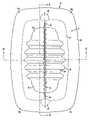
- FIG. 2depicts a base structure of an exemplary embodiment of a hot-fill container according to the present invention
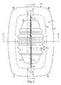
- FIG. 3depicts a perspective view of a base structure of an exemplary embodiment of a hot-fill structure according to the present invention
- FIG. 4depicts a perspective view of a base structure of an exemplary embodiment of a hot-fill structure according to the present invention
- FIG. 5depicts a cross-sectional view along section line 5 - 5 in FIG. 2 ;
- FIG. 6depicts a cross-sectional view along section line 6 - 6 in FIG. 2 .
- a corrugated support flutemost commonly used in laundry detergent containers that are not hot-filled, includes any number of corrugations to provide resistance against sagging caused by the weight of the liquid itself.
- the corrugated support flutesalso provides structure to assist the base in maintaining its designed shape and resisting warpage while the plastic is cooling prior to the filling process.
- a fincan be constructed into the pinch area of the base to give additional stability to the area in the base where pieces of parison fuse together.
- a fincan provide a larger area near the base of the bottle for the pieces of parison to amalgamate and adhere to each other.
- the finalso provides structure to assist the base in maintaining its designed shape and resisting warpage while the plastic is cooling prior to the filling process.
- these structureswhen used independently, tend to be less effective.
- a one gallon container having corrugations aloneis less desirable because it would require a push-up so deep that the undercuts in the mold may not be pulled through when the container is released from the mold.
- a corrugated support flute alonemay not provide for adequate adhesion and cause the plastic in the base to pull apart.
- a fin aloneis less desirable because although it may provide for adequate adhesion, it will not likely provide enough support to prevent sagging.
- FIG. 1illustrates an exemplary embodiment of a blow-molded plastic container 10 , such as may be used in the sale of juices and non-carbonated beverages.
- Container 10can typically be designed to contain liquid volumes of one gallon, 64 ounces, or the like.
- Container 10can have a neck portion 11 defining an opening 12 allowing for pouring and filling of a beverage.
- Neck portion 11merges with sidewall 13 .
- sidewall 13can have any number of sides.
- container 10has 4 sides defined by the container's rectangular cross-sectional shape.
- Sidewall 13can also include upper label bumper 17 and lower label bumper 18 . These label bumpers can be positioned on container 10 near where sidewall 13 merges with neck portion 11 and base structure 14 , respectively.
- Sidewall 13merges with base structure 14 opposite neck portion 11 .
- Container 10is designed to receive a cap (not shown) during the hot-fill process to seal the container and confine the beverage inside the container.
- sidewall 13is shown as a rectangular cross-sectional sidewall, any shape can be utilized, such as a square or triangular cross-sectional sidewall, or a cylinder. It is understood by people having ordinary skill in the art that the edges of the container can be rounded and although the container may be rectangular, the edges may not form perfect right angles. In such an embodiment, base structure 14 would be shaped appropriately to merge with sidewall 13 .
- Container 10can also include a handle 16 for receiving the grip of a consumer's hand. As shown in FIG. 5 , handle 16 can be hollow and thus able to store fluid when container 10 is filled.
- Base structure 14can be arcuate or dome-like such that the base of the container can define touch points at which the base of the container makes contact with a horizontal surface (not shown).
- base structure 14 of container 10can be arched towards the center of the container so as to define four touch points 15 a - d as shown in FIGS. 1-4 .
- the archingcan ensure that no portion of base structure 14 sags below touch points 15 a - d . This arching up into the center of container 10 can be called rocker correction.
- base structure 14also can include structure that can, among other things, prevent sagging.
- base structure 14has an annular support heel 21 .
- Support heel 21allows container 10 to be supported erect on a horizontal surface.
- support heel 21can have any number of sides, depending on the cross-sectional shape of the container.
- support heel 21can have 4 sides that are defined by the container's rectangle cross-sectional shape. Two of these sides can extend substantially parallel to each other in a longitudinal direction, while the other two sides can extend substantially parallel to each other in a direction that is transverse to the longitudinal direction.
- each side of support heel 21can be arched toward the center of container 10 to define touch points 15 a - d .
- the apex of the arc that extends in the longitudinal directioncan be, for example, 0.080 inches from touch points 15 a - d .
- the apex of the arc extending in the transverse directioncan be, for example, 0.120 inches from touch points 15 a - d.
- Annular support heel 21can have an inner and an outer portion, 22 and 23 , respectively. Outer portion 23 merges with the container's sidewall 13 .
- the inner portion of the annular support heel, which merges with a corrugated support flute 24can have an upwardly inclined surface that angles upward from support heel 21 to corrugated support flute 24 , as shown in FIGS. 3 and 4 .
- the upwardly inclined surface of inner portion 22can be as inclined as possible so long as the undercuts in the mold can be pulled through once the container is blown. Otherwise, if the upwardly inclined surface of inner portion 22 is at too great of an inclination, the undercuts in the mold may cock the container in a sideways direction and not allow the container to be released from the mold properly.
- Corrugated support flute 24can have any number of corrugations (ribs) 29 extending across any portion of corrugated support flute 24 .
- corrugated support flute 24can have 5 corrugations 29 .
- each corrugation 29can have a width “w” that extends between the centers of adjacent corrugations 29 and a depth “d” that extends from the top of the inside of base structure 14 down into each corrugation 29 .
- corrugated support flute 24can also have flat surfaces 51 a - b that can connect the outer-most corrugations 29 to inner portion 22 of annular support heel 21 . Surfaces 51 a - b can receive engraved symbols such as, for example, the SPI recycling code, the manufacturer's logo, the cavity number, or the set designation.
- fin 25Positioned transverse to the corrugated support flute 24 is a fin 25 . It can be understood by a person having ordinary skill in the art that fin 25 will be located in the pinch area of base structure 14 of container 10 . Fin 25 can extend in a longitudinal direction, for example, and intersect any portion of any of corrugations 29 of corrugated support flute 24 . In a preferred embodiment, fin 25 can intersect all corrugations 29 of corrugated support flute 24 through the center of each corrugation 29 , as shown in FIGS. 2-5 .
- Fin 25can have a beam 26 extending transverse to corrugated support flute 24 and a plurality of protrusions 27 that are alternatively positioned on either side of beam 26 to form a so-called zippered pinch.
- Beam 26can extend in a longitudinal direction, for example, and merge with inner portion 22 of annular support heel 21 .
- the alternatively positioned protrusions 27may overlap.
- beam 26may extend below protrusions 27 .
- the top side of fin 25can follow the contour of corrugations 29 of corrugated support flute 24 .
- protrusions 27may also follow the contour of corrugations 29 of corrugated support flute 24 .
- base structure 14can have tunnels 28 .
- the moldtypically contains flash pockets above and below the cavity in the mold to capture the excess of the parison that is captured in the flash pockets above and below the cavity.
- Tunnels 28can provide a channel for the excess parison to travel through as the excess parison is forced into the flash pockets.
- corrugated support flute 24 and the positioning of fin 25 transverse to the corrugated support flutethat allows the base structure of the present invention to provide the desired structural integrity of the container bottom.
- the support flute and the zipper pinchwill act in a manner to withstand the changes in temperature, pressure, and volume within the container during the hot-fill process, as well as other forces applied to it during the construction, transportation, and storage of the container.
- the support flute and the zipper pinchcooperate to resist sagging of the base by providing the necessary structure to withstand all forces applied to the container. Additionally, the vertical beam and zipper pinch of the fin resists deformation of the base structure.
Landscapes
- Engineering & Computer Science (AREA)
- Mechanical Engineering (AREA)
- Manufacturing & Machinery (AREA)
- Ceramic Engineering (AREA)
- Containers Having Bodies Formed In One Piece (AREA)
- Package Specialized In Special Use (AREA)
- Packages (AREA)
Abstract
Description
Claims (24)
Priority Applications (1)
| Application Number | Priority Date | Filing Date | Title |
|---|---|---|---|
| US11/284,970US7464826B2 (en) | 2003-02-24 | 2005-11-23 | Hot-fill container base structure |
Applications Claiming Priority (2)
| Application Number | Priority Date | Filing Date | Title |
|---|---|---|---|
| US10/370,571US7000793B2 (en) | 2003-02-24 | 2003-02-24 | Hot-fill container base structure |
| US11/284,970US7464826B2 (en) | 2003-02-24 | 2005-11-23 | Hot-fill container base structure |
Related Parent Applications (1)
| Application Number | Title | Priority Date | Filing Date |
|---|---|---|---|
| US10/370,571ContinuationUS7000793B2 (en) | 2003-02-24 | 2003-02-24 | Hot-fill container base structure |
Publications (2)
| Publication Number | Publication Date |
|---|---|
| US20060070974A1 US20060070974A1 (en) | 2006-04-06 |
| US7464826B2true US7464826B2 (en) | 2008-12-16 |
Family
ID=32868189
Family Applications (2)
| Application Number | Title | Priority Date | Filing Date |
|---|---|---|---|
| US10/370,571Expired - LifetimeUS7000793B2 (en) | 2003-02-24 | 2003-02-24 | Hot-fill container base structure |
| US11/284,970Expired - LifetimeUS7464826B2 (en) | 2003-02-24 | 2005-11-23 | Hot-fill container base structure |
Family Applications Before (1)
| Application Number | Title | Priority Date | Filing Date |
|---|---|---|---|
| US10/370,571Expired - LifetimeUS7000793B2 (en) | 2003-02-24 | 2003-02-24 | Hot-fill container base structure |
Country Status (6)
| Country | Link |
|---|---|
| US (2) | US7000793B2 (en) |
| EP (1) | EP1597154A4 (en) |
| BR (1) | BRPI0407776A (en) |
| CA (1) | CA2516787A1 (en) |
| MX (1) | MXPA05009030A (en) |
| WO (1) | WO2004076292A2 (en) |
Cited By (2)
| Publication number | Priority date | Publication date | Assignee | Title |
|---|---|---|---|---|
| US20070276802A1 (en)* | 2006-05-15 | 2007-11-29 | Piedmonte Christopher M | Systems and Methods for Providing Data Sets Using a Store of Albegraic Relations |
| US20160136867A1 (en)* | 2013-07-08 | 2016-05-19 | Isp Technology Ag | Plastics connecting seam, plastics bottle with a connecting seam and method for the production thereof |
Families Citing this family (10)
| Publication number | Priority date | Publication date | Assignee | Title |
|---|---|---|---|---|
| US7000793B2 (en)* | 2003-02-24 | 2006-02-21 | Graham Packaging Co., L.P. | Hot-fill container base structure |
| US20060163248A1 (en)* | 2005-01-26 | 2006-07-27 | Graham Packaging Company, L.P. | Base for top-down storage vessel |
| WO2009091885A1 (en)* | 2008-01-16 | 2009-07-23 | Babak Baban | Health beverages comprising cinnamon extract and methods of making and using the same |
| GB0918744D0 (en)* | 2009-10-26 | 2009-12-09 | Nampak Plastics Europe Ltd | Plastic container |
| US8783505B2 (en)* | 2012-05-30 | 2014-07-22 | Graham Packaging Company, L.P. | Retortable plastic containers |
| US20140166609A1 (en)* | 2012-12-19 | 2014-06-19 | Graham Packaging Company, L.P. | Reinforced plastic containers |
| JP6672060B2 (en)* | 2016-04-28 | 2020-03-25 | 株式会社吉野工業所 | Delamination container |
| JP2018177301A (en)* | 2017-04-13 | 2018-11-15 | 株式会社吉野工業所 | Handled bottle |
| JP7350430B2 (en)* | 2019-07-31 | 2023-09-26 | 株式会社吉野工業所 | extrusion blow molded containers |
| JP7438633B2 (en)* | 2020-06-30 | 2024-02-27 | 株式会社吉野工業所 | double container |
Citations (22)
| Publication number | Priority date | Publication date | Assignee | Title |
|---|---|---|---|---|
| US2988258A (en) | 1957-12-17 | 1961-06-13 | Helen G Witzke | Cup |
| US3140796A (en) | 1962-08-22 | 1964-07-14 | Sigma Chem Co | Planchet |
| US3371898A (en) | 1966-06-10 | 1968-03-05 | Atlantic Prod Corp | Golf bag bottom having venting openings |
| US3403804A (en)* | 1965-12-10 | 1968-10-01 | L M P Lavorazione Materie Plas | Blown bottle of flexible plastics |
| US3417892A (en)* | 1964-05-11 | 1968-12-24 | Shell Oil Co | Containers with squeezed bottom seam |
| US3468443A (en) | 1967-10-06 | 1969-09-23 | Apl Corp | Base of plastic container for storing fluids under pressure |
| US3563445A (en) | 1968-09-11 | 1971-02-16 | Mobil Oil Corp | Plastic tray structures |
| US3592885A (en)* | 1968-12-13 | 1971-07-13 | Phillips Petroleum Co | Corrugated parison real line |
| US3687593A (en)* | 1971-01-04 | 1972-08-29 | Phillips Petroleum Co | Alternate projections in sealing member |
| US3757978A (en)* | 1971-12-22 | 1973-09-11 | Phillips Petroleum Co | Biaxially oriented blow molded article with ribs parallel to seam |
| US4134510A (en) | 1975-06-16 | 1979-01-16 | Owens-Illinois, Inc. | Bottle having ribbed bottom |
| GB2164914A (en) | 1984-10-02 | 1986-04-03 | Bell Products Limited | A petrol can |
| US4759454A (en)* | 1986-12-29 | 1988-07-26 | Owens-Illinois Plastic Products Inc. | Hollow plastic bottle with wrap-around label |
| US4989738A (en)* | 1989-10-13 | 1991-02-05 | General Electric Company | Plastic bottle with reinforced concave bottom |
| JPH04352688A (en) | 1991-05-22 | 1992-12-07 | Sekisui Chem Co Ltd | Container |
| US5460292A (en) | 1993-07-09 | 1995-10-24 | Holman; Don | Agricultural container with corner struts |
| US5503283A (en) | 1994-11-14 | 1996-04-02 | Graham Packaging Corporation | Blow-molded container base structure |
| US5685452A (en) | 1992-10-21 | 1997-11-11 | Perstorp Ab | Container bottom with elevations made of a polymeric material and a process for production thereof |
| US5799809A (en)* | 1995-02-16 | 1998-09-01 | Yoshino Kogyosho Co., Ltd. | Blow molded container and blow mold thereof |
| US6464106B1 (en)* | 1996-12-31 | 2002-10-15 | Lever Brothers Company, Division Of Conopco, Inc. | Stress crack resistant bottle |
| US6619501B2 (en) | 2001-07-19 | 2003-09-16 | Pactiv Corporation | Base for food containers |
| US7000793B2 (en)* | 2003-02-24 | 2006-02-21 | Graham Packaging Co., L.P. | Hot-fill container base structure |
Family Cites Families (3)
| Publication number | Priority date | Publication date | Assignee | Title |
|---|---|---|---|---|
| US4054219A (en)* | 1976-05-26 | 1977-10-18 | Beatrice Foods | Drainable container base |
| NL9201806A (en)* | 1992-10-16 | 1994-05-16 | Inex Nv | Packaging for two liters of milk. |
| DE10058122A1 (en)* | 2000-11-22 | 2002-06-06 | Heinz Plastics Gmbh | Plastic bottle has base which is raised inwards to form dome which is reinforced by radial grooves or ribs, one of which can be squeezed together |
- 2003
- 2003-02-24USUS10/370,571patent/US7000793B2/ennot_activeExpired - Lifetime
- 2004
- 2004-02-13CACA002516787Apatent/CA2516787A1/ennot_activeAbandoned
- 2004-02-13BRBRPI0407776-8Apatent/BRPI0407776A/ennot_activeIP Right Cessation
- 2004-02-13MXMXPA05009030Apatent/MXPA05009030A/enactiveIP Right Grant
- 2004-02-13EPEP04711196Apatent/EP1597154A4/ennot_activeWithdrawn
- 2004-02-13WOPCT/US2004/004361patent/WO2004076292A2/enactiveApplication Filing
- 2005
- 2005-11-23USUS11/284,970patent/US7464826B2/ennot_activeExpired - Lifetime
Patent Citations (22)
| Publication number | Priority date | Publication date | Assignee | Title |
|---|---|---|---|---|
| US2988258A (en) | 1957-12-17 | 1961-06-13 | Helen G Witzke | Cup |
| US3140796A (en) | 1962-08-22 | 1964-07-14 | Sigma Chem Co | Planchet |
| US3417892A (en)* | 1964-05-11 | 1968-12-24 | Shell Oil Co | Containers with squeezed bottom seam |
| US3403804A (en)* | 1965-12-10 | 1968-10-01 | L M P Lavorazione Materie Plas | Blown bottle of flexible plastics |
| US3371898A (en) | 1966-06-10 | 1968-03-05 | Atlantic Prod Corp | Golf bag bottom having venting openings |
| US3468443A (en) | 1967-10-06 | 1969-09-23 | Apl Corp | Base of plastic container for storing fluids under pressure |
| US3563445A (en) | 1968-09-11 | 1971-02-16 | Mobil Oil Corp | Plastic tray structures |
| US3592885A (en)* | 1968-12-13 | 1971-07-13 | Phillips Petroleum Co | Corrugated parison real line |
| US3687593A (en)* | 1971-01-04 | 1972-08-29 | Phillips Petroleum Co | Alternate projections in sealing member |
| US3757978A (en)* | 1971-12-22 | 1973-09-11 | Phillips Petroleum Co | Biaxially oriented blow molded article with ribs parallel to seam |
| US4134510A (en) | 1975-06-16 | 1979-01-16 | Owens-Illinois, Inc. | Bottle having ribbed bottom |
| GB2164914A (en) | 1984-10-02 | 1986-04-03 | Bell Products Limited | A petrol can |
| US4759454A (en)* | 1986-12-29 | 1988-07-26 | Owens-Illinois Plastic Products Inc. | Hollow plastic bottle with wrap-around label |
| US4989738A (en)* | 1989-10-13 | 1991-02-05 | General Electric Company | Plastic bottle with reinforced concave bottom |
| JPH04352688A (en) | 1991-05-22 | 1992-12-07 | Sekisui Chem Co Ltd | Container |
| US5685452A (en) | 1992-10-21 | 1997-11-11 | Perstorp Ab | Container bottom with elevations made of a polymeric material and a process for production thereof |
| US5460292A (en) | 1993-07-09 | 1995-10-24 | Holman; Don | Agricultural container with corner struts |
| US5503283A (en) | 1994-11-14 | 1996-04-02 | Graham Packaging Corporation | Blow-molded container base structure |
| US5799809A (en)* | 1995-02-16 | 1998-09-01 | Yoshino Kogyosho Co., Ltd. | Blow molded container and blow mold thereof |
| US6464106B1 (en)* | 1996-12-31 | 2002-10-15 | Lever Brothers Company, Division Of Conopco, Inc. | Stress crack resistant bottle |
| US6619501B2 (en) | 2001-07-19 | 2003-09-16 | Pactiv Corporation | Base for food containers |
| US7000793B2 (en)* | 2003-02-24 | 2006-02-21 | Graham Packaging Co., L.P. | Hot-fill container base structure |
Cited By (3)
| Publication number | Priority date | Publication date | Assignee | Title |
|---|---|---|---|---|
| US20070276802A1 (en)* | 2006-05-15 | 2007-11-29 | Piedmonte Christopher M | Systems and Methods for Providing Data Sets Using a Store of Albegraic Relations |
| US20160136867A1 (en)* | 2013-07-08 | 2016-05-19 | Isp Technology Ag | Plastics connecting seam, plastics bottle with a connecting seam and method for the production thereof |
| US10207450B2 (en)* | 2013-07-08 | 2019-02-19 | Isp Technology Ag | Plastics connecting seam, plastics bottle with a connecting seam and method for the production thereof |
Also Published As
| Publication number | Publication date |
|---|---|
| CA2516787A1 (en) | 2004-09-10 |
| US20060070974A1 (en) | 2006-04-06 |
| EP1597154A4 (en) | 2009-07-29 |
| US20040164044A1 (en) | 2004-08-26 |
| WO2004076292A2 (en) | 2004-09-10 |
| MXPA05009030A (en) | 2006-04-07 |
| BRPI0407776A (en) | 2006-02-14 |
| US7000793B2 (en) | 2006-02-21 |
| EP1597154A2 (en) | 2005-11-23 |
| WO2004076292A3 (en) | 2005-03-24 |
Similar Documents
| Publication | Publication Date | Title |
|---|---|---|
| US7137521B2 (en) | Plastic container having chamfered corners for improved top-loading strength | |
| AU2006304383B2 (en) | A repositionable base structure for a container | |
| US10099834B2 (en) | Pressure container with differential vacuum panels | |
| US5908127A (en) | Load bearing polymeric container | |
| US8567624B2 (en) | Lightweight, high strength bottle | |
| US8596479B2 (en) | Hot-fill container | |
| US7874442B2 (en) | Hot-fill plastic container with ribs and grip | |
| US8567622B2 (en) | Dome shaped hot-fill container | |
| CA2540427C (en) | Bottle with reinforced top portion | |
| US7464826B2 (en) | Hot-fill container base structure | |
| US20070075032A1 (en) | Multi-panel plastic container | |
| US5071015A (en) | Blow molded PET container with ribbed base structure | |
| US7140505B2 (en) | Base design for pasteurization | |
| US20090095702A1 (en) | Hot-fillable container and method of making | |
| US20060065566A1 (en) | Container having label protection feature | |
| US7252205B2 (en) | Plastic container with top handle | |
| JP2020063065A (en) | Plastic bottle | |
| AU2011203263B2 (en) | System and method for handling a container with a vacuum panel in the container body |
Legal Events
| Date | Code | Title | Description |
|---|---|---|---|
| STCF | Information on status: patent grant | Free format text:PATENTED CASE | |
| AS | Assignment | Owner name:REYNOLDS GROUP HOLDINGS INC., NEW ZEALAND Free format text:SECURITY AGREEMENT;ASSIGNOR:GRAHAM PACKAGING COMPANY, L.P.;REEL/FRAME:026970/0699 Effective date:20110908 | |
| AS | Assignment | Owner name:GRAHAM PACKAGING COMPANY, L.P., PENNSYLVANIA Free format text:TERMINATION AND RELEASE OF SECURITY INTEREST IN PATENTS;ASSIGNOR:REYNOLDS GROUP HOLDINGS INC.;REEL/FRAME:027895/0738 Effective date:20120320 | |
| AS | Assignment | Owner name:THE BANK OF NEW YORK MELLON, NEW YORK Free format text:PATENT SECURITY AGREEMENT;ASSIGNOR:GRAHAM PACKAGING COMPANY, L.P.;REEL/FRAME:027910/0609 Effective date:20120320 | |
| FPAY | Fee payment | Year of fee payment:4 | |
| FPAY | Fee payment | Year of fee payment:8 | |
| MAFP | Maintenance fee payment | Free format text:PAYMENT OF MAINTENANCE FEE, 12TH YEAR, LARGE ENTITY (ORIGINAL EVENT CODE: M1553); ENTITY STATUS OF PATENT OWNER: LARGE ENTITY Year of fee payment:12 | |
| AS | Assignment | Owner name:GRAHAM PACKAGING COMPANY, L.P., PENNSYLVANIA Free format text:RELEASE OF SECURITY INTEREST IN CERTAIN PATENT COLLATERAL;ASSIGNOR:THE BANK OF NEW YORK MELLON, AS THE COLLATERAL AGENT AND TRUSTEE;REEL/FRAME:053396/0531 Effective date:20200804 Owner name:CREDIT SUISSE AG, CAYMAN ISLANDS BRANCH, AS ADMINISTRATIVE AGENT, NEW YORK Free format text:SECURITY INTEREST;ASSIGNORS:GRAHAM PACKAGING COMPANY, L.P.;GRAHAM PACKAGING PET TECHNOLOGIES INC.;GRAHAM PACKAGING PLASTIC PRODUCTS LLC;REEL/FRAME:053398/0381 Effective date:20200804 |