US7464781B2 - Three-wheeled vehicle having a split radiator and an interior storage compartment - Google Patents
Three-wheeled vehicle having a split radiator and an interior storage compartmentDownload PDFInfo
- Publication number
- US7464781B2 US7464781B2US10/505,335US50533505AUS7464781B2US 7464781 B2US7464781 B2US 7464781B2US 50533505 AUS50533505 AUS 50533505AUS 7464781 B2US7464781 B2US 7464781B2
- Authority
- US
- United States
- Prior art keywords
- radiator
- frame
- storage compartment
- engine
- vehicle according
- Prior art date
- Legal status (The legal status is an assumption and is not a legal conclusion. Google has not performed a legal analysis and makes no representation as to the accuracy of the status listed.)
- Expired - Lifetime, expires
Links
- 238000001816coolingMethods0.000claimsdescription23
- 239000000725suspensionSubstances0.000claimsdescription12
- 238000010276constructionMethods0.000claimsdescription2
- 238000013022ventingMethods0.000claims3
- 239000003921oilSubstances0.000description13
- 238000006243chemical reactionMethods0.000description11
- 230000005484gravityEffects0.000description10
- 238000002485combustion reactionMethods0.000description8
- 230000000712assemblyEffects0.000description3
- 238000000429assemblyMethods0.000description3
- 239000002826coolantSubstances0.000description3
- 206010060800Hot flushDiseases0.000description2
- 210000002414legAnatomy0.000description2
- 238000012986modificationMethods0.000description2
- 230000004048modificationEffects0.000description2
- 239000010705motor oilSubstances0.000description2
- XLYOFNOQVPJJNP-UHFFFAOYSA-NwaterSubstancesOXLYOFNOQVPJJNP-UHFFFAOYSA-N0.000description2
- YXIWHUQXZSMYRE-UHFFFAOYSA-N1,3-benzothiazole-2-thiolChemical compoundC1=CC=C2SC(S)=NC2=C1YXIWHUQXZSMYRE-UHFFFAOYSA-N0.000description1
- 239000006096absorbing agentSubstances0.000description1
- 230000003466anti-cipated effectEffects0.000description1
- 238000006073displacement reactionMethods0.000description1
- 239000011152fibreglassSubstances0.000description1
- 239000002828fuel tankSubstances0.000description1
- 230000003116impacting effectEffects0.000description1
- 210000003127kneeAnatomy0.000description1
- 239000007788liquidSubstances0.000description1
- 239000000463materialSubstances0.000description1
- 229920000642polymerPolymers0.000description1
- 239000011435rockSubstances0.000description1
- 230000035939shockEffects0.000description1
Images


Classifications
- B—PERFORMING OPERATIONS; TRANSPORTING
- B62—LAND VEHICLES FOR TRAVELLING OTHERWISE THAN ON RAILS
- B62K—CYCLES; CYCLE FRAMES; CYCLE STEERING DEVICES; RIDER-OPERATED TERMINAL CONTROLS SPECIALLY ADAPTED FOR CYCLES; CYCLE AXLE SUSPENSIONS; CYCLE SIDE-CARS, FORECARS, OR THE LIKE
- B62K5/00—Cycles with handlebars, equipped with three or more main road wheels
- B62K5/02—Tricycles
- B62K5/05—Tricycles characterised by a single rear wheel
- B—PERFORMING OPERATIONS; TRANSPORTING
- B60—VEHICLES IN GENERAL
- B60K—ARRANGEMENT OR MOUNTING OF PROPULSION UNITS OR OF TRANSMISSIONS IN VEHICLES; ARRANGEMENT OR MOUNTING OF PLURAL DIVERSE PRIME-MOVERS IN VEHICLES; AUXILIARY DRIVES FOR VEHICLES; INSTRUMENTATION OR DASHBOARDS FOR VEHICLES; ARRANGEMENTS IN CONNECTION WITH COOLING, AIR INTAKE, GAS EXHAUST OR FUEL SUPPLY OF PROPULSION UNITS IN VEHICLES
- B60K11/00—Arrangement in connection with cooling of propulsion units
- B60K11/02—Arrangement in connection with cooling of propulsion units with liquid cooling
- B60K11/04—Arrangement or mounting of radiators, radiator shutters, or radiator blinds
- B—PERFORMING OPERATIONS; TRANSPORTING
- B62—LAND VEHICLES FOR TRAVELLING OTHERWISE THAN ON RAILS
- B62K—CYCLES; CYCLE FRAMES; CYCLE STEERING DEVICES; RIDER-OPERATED TERMINAL CONTROLS SPECIALLY ADAPTED FOR CYCLES; CYCLE AXLE SUSPENSIONS; CYCLE SIDE-CARS, FORECARS, OR THE LIKE
- B62K5/00—Cycles with handlebars, equipped with three or more main road wheels
- B62K5/02—Tricycles
- B62K5/027—Motorcycles with three wheels
- B—PERFORMING OPERATIONS; TRANSPORTING
- B60—VEHICLES IN GENERAL
- B60Y—INDEXING SCHEME RELATING TO ASPECTS CROSS-CUTTING VEHICLE TECHNOLOGY
- B60Y2200/00—Type of vehicle
- B60Y2200/10—Road Vehicles
- B60Y2200/12—Motorcycles, Trikes; Quads; Scooters
- B—PERFORMING OPERATIONS; TRANSPORTING
- B60—VEHICLES IN GENERAL
- B60Y—INDEXING SCHEME RELATING TO ASPECTS CROSS-CUTTING VEHICLE TECHNOLOGY
- B60Y2200/00—Type of vehicle
- B60Y2200/10—Road Vehicles
- B60Y2200/12—Motorcycles, Trikes; Quads; Scooters
- B60Y2200/124—Buggies, Quads
Definitions
- the present inventionrelates to the overall design and construction of a novel three-wheeled vehicle designed for road use.
- the present inventionrelates to a novel three-wheeled straddle-type vehicle having a split radiator associated with the engine.
- the split radiatorincludes a pair of radiators that are fluidly connected and located on opposite sides of the vehicle frame, whereby a storage compartment may be located in the front of the vehicle normally reserved for the radiator.
- ATVall terrain vehicle
- the cooling system and in particular the radiator associated with the engine for an ATVis typically located in the front center of the vehicle.
- the radiatoris also positioned fairly high on the vehicle so that the radiator is not slashed with mud. This arrangement does not permit the location of a storage compartment in the front of the vehicle.
- ATV'stypically have a higher center of gravity compared to other vehicles. To lower the center of gravity, the radiator in the ATV may be forwardly disposed at an angle. The angle, however, must be greater than 45° so that the radiator will not contact the ground when the ATV travels down a hill.
- U.S. Pat. No. 4,787,470discloses a three-wheeled vehicle with two front wheels and a sole rear wheel having a body formed by an ATV frame carrying two front and one rear fenders and a saddle type seat. An engine is supported on the frame but is exposed to the exterior of the vehicle body, much like as done in motorcycles. In such a vehicle, the center of gravity of the rider and the vehicle are located higher off the ground than the vehicle contemplated by the present invention.
- Another known vehicleis the motorcycle having one front wheel and one or more rear wheels.
- the radiator for the cooling systemis located in the front center of the motorcycle. With this arrangement, the motorcycle has a higher center of gravity. The location of the radiator is fixed so that it does not contact the rider and interrupt the handling of the motorcycle. This location of the radiator does not permit a forwardly located storage compartment.
- Another vehicleis a snowmobile, which is designed for trail use and off-train use.
- the radiator associated with the cooling system for the snowmobileis located in the rear center of the snowmobile in the tunnel beneath the snowmobile. With this location, snow from the drive belt contacts the radiator to cool the engine.
- U.S. Pat. No. 4,662,468also discloses a three-wheeled vehicle with two front wheels and a sole rear wheel.
- the three-wheeled vehicle of the '468 patentuses a conventional snowmobile chassis, which has been modified to attach two driving wheels at its front portion.
- U.S. Pat. No. 5,564,517discloses a snowmobile conversion frame kit which includes a frame having two wheels with a steering assembly in the front and a single wheel with a swing arm in the rear.
- the kit in the '517 patentis designed to be secured to a conventional snowmobile chassis also.
- Conventional snowmobile chassisoffer less rigidity and structural strength than are required for the all-terrain vehicles. None of these vehicles provide adequate cooling for a three-wheeled vehicle having a low center of gravity as contemplated by the present invention.
- the present inventionrelates to a three-wheeled straddle-type vehicle having two wheels in the front of the vehicle and one wheel in the rear of the vehicle.
- the cooling systemincludes a split radiator arrangement whereby the cooling system can be located lower to the ground to improve the vehicle's center of gravity. Furthermore, the relocation of the cooling system from the front to the sides of the vehicle opens up the front portion of the vehicle for storage, which is lacking in the prior art vehicles.
- a notable aspect of the three-wheeled vehicle of the present inventionis that it is designed to operate with an engine capable of generating 80-135 horsepower or even greater and that it is intended for road use.
- Many of the three-wheeled vehicles heretofore availablehave been mostly capable of 30 horsepower (hp), and especially less than 100 hp, due to limitations in the structural strength of the frame and the maneuverability and stability of the vehicle.
- the novel head pipeless frame assembly of the three-wheeled vehicle of the present inventionprovides sufficient structural rigidity to withstand the forces experienced during high performance operation of the vehicle. Further, with the improved positioning of the center of gravity of the rider vis-á-vis the center of vehicle, the present invention alleviates the problems of instability and lack of control in sharp turns or during abrupt directional changes.
- the three-wheeled vehicleincludes a frame having a front portion and a rear portion.
- a pair of front wheelsare rotatably connected to the front portion of the frame.
- a single rear wheelis rotatably connected to the rear portion of the frame.
- the vehiclefurther includes a straddle type vehicle seat connected to the frame.
- the vehiclefurther includes an internal combustion engine connected to the frame. The internal combustion engine provides power to drive the pair of front wheels.
- the internal combustion engineincludes a radiator system for cooling the engine.
- the radiator systemincludes a pair of radiators.
- a first radiatoris located on one side of the frame.
- a second radiatoris located on an opposite side of the frame.
- the radiatorsmay be operated in series or parallel. When connected in series, the pressure needed form the pump is higher because the hydraulic circuit resistance is bigger. When connected in parallel the hydraulic circuit resistance is smaller. Such a parallel arrangement, however, provides a limp home function in the event of a failure of one of the radiators.
- the second radiatoris spaced from the first radiator.
- Each of the first and second radiators of the radiatorare located rearwardly of the pair of front wheels.
- the radiatorsare located a sufficient distance behind the wheels so that a clearance exists between the wheels and the radiators when the wheels are turned to a maximum.
- the first and second radiatorsmay be located at an angle with respect to the vertical axis and longitudinal axis of the vehicle.
- the first and second radiatorsmay be forwardly facing and disposed at an angle with respect to a vertical axis of the vehicle. It is contemplated that the first and second radiators may be disposed at angle of up to 45° with respect to the vertical axis.
- the first and second radiators of the radiatorincludes an upper portion and a lower portion. In accordance with the present invention, the upper portion may be located closer to the front portion of the frame than the lower portion.
- Each radiatormay include a cooling fan located on the rear surface of the radiator.
- the cooling fansare provided to direct air from the radiators away from the riders.
- the fanspreferably direct the air rearwardly under the vehicle to reduce drag. This arrangement also serves to flush hot air from beneath the vehicle, which may assist in engine cooling.
- the vehicle contemplated in accordance with the present inventionis intended for road use. It is anticipated that these vehicles may be used during cooler seasons and in cooler climates.
- the radiators employed in the present inventionare enclosed with covers that are located adjacent the operator's feet. It is contemplated that vents can be provided in the radiator covers to direct the air onto the feet and knees of the rider to provide a heat source. These vents may be selectively operated such that they are open when the vehicle is used in cooler environments.
- first and second radiatorsmay be disposed at an angle with respect to the longitudinal axis or centerline of the vehicle.
- the first and second radiatorsmay be disposed at angle in a range of 45° to 135° with respect to the longitudinal axis.
- the first and second radiatorsinclude an inner portion and an outer portion.
- the inner portionis located adjacent the frame assembly.
- the inner portionmay be located closer to the front portion of the frame than the outer portion.
- the outer portionmay be located closer to the front portion of the frame than the inner portion.
- the vehiclefurther includes a fairing assembly enclosing at least the front portion of the frame.
- the fairing assemblyincludes a first radiator enclosure for enclosing at least a portion of the first radiator and a second radiator enclosure for enclosing at least a portion of the second radiator.
- the radiator enclosuresmay be provided with selectively operable units to direct warm air from the radiators onto the driver during cooler operating conditions. Since the vehicle is intended for road use, it is desirable to provide a storage compartment for the rider to store objects during use (e.g., a briefcase, backpack, etc.) and while not in use (e.g., a helmet).
- the front portion of the frameincludes a cavity, which forms a storage compartment.
- the fairing assemblyincludes a removable cover to provide access to the cavity. The cavity may provide access to at least a portion of the internal combustion engine and an engine service center. The location of the radiators on the side of the vehicle increases the size of the storage area.
- the vehiclefurther includes an air inlet passageway formed in the front portion of the frame.
- An oil cooler assemblyis connected to the internal combustion engine for cooling engine oil circulating through the internal combustion engine.
- a flow of airis directed through the air inlet passageway over the oil cooler assembly to cool the oil in the oil cooler assembly.
- the oil cooler assemblyis located between the first radiator and the second radiator.
- the provision of the cooling passagewaypermits the oil cooler to be located closer to the engine, which reduces the amount of hoses and other connections necessary to link the oil cooler to the engine.
- the air inlet passagewaymay also be used to direct a flow of air onto the radiators.
- the radiatorsare still located on opposite sides of the vehicle, but are substantially parallel to the longitudinal axis of the vehicle.
- a flow directordirects the flow of air from the inlet towards the radiators.
- FIG. 1is a front view of the three-wheeled straddle-type vehicle in accordance with an embodiment of the present invention
- FIG. 2is a right side view of the three-wheeled straddle-type vehicle of FIG. 1 ;
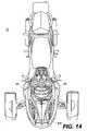
- FIG. 3is a top view of the three-wheeled straddle-type vehicle of FIG. 1 ;
- FIG. 4is a front left perspective view of the frame assembly for the three-wheeled straddle-type vehicle of FIGS. 1-3 ;
- FIG. 5is a partial schematic side view of the vehicle in accordance with the present invention illustrating the split radiator and cooling assembly
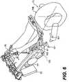
- FIG. 6is a partial left rear schematic side view of the vehicle illustrating the split radiator and cooling assembly
- FIG. 7is a front view of the radiator cover of the fairing assembly
- FIG. 8is a side view of the radiator cover of the fairing assembly
- FIG. 9is a front right perspective view of the radiator cover of the fairing assembly.
- FIG. 10is a rear perspective view of one radiator of the split radiator in accordance with the present invention.
- FIG. 11is a left front perspective view of the storage compartment in the front portion of the fairing assembly
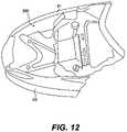
- FIG. 12is a front top view of the storage compartment in the front portion of the fairing assembly
- FIG. 13is a top schematic view illustrating one orientation of the first and second radiators, shown in phantom, disposed at an angle with respect to the longitudinal axis of the vehicle;
- FIG. 14is a top schematic view illustrating another orientation of the first and second radiators, shown in phantom, disposed at an angle with respect to the longitudinal axis of the vehicle;
- FIG. 15is a top schematic view illustrating another orientation of the first and second radiators, shown in phantom, parallel to the longitudinal axis of the vehicle;
- FIG. 16is a top schematic view illustrating another orientation of a single radiator, shown in phantom, located in the front of the wheel;
- FIG. 17is a top schematic view illustrating another orientation of a single radiator, shown in phantom, located in the rear of the vehicle;
- FIG. 18is a side view of a conventional motorcycle that has been converted into a three-wheel vehicle.
- FIG. 19is a partial side view of the conventional thee-wheel vehicle of FIG. 18 .
- FIGS. 1-3A three-wheeled straddle type vehicle 10 in accordance with the present invention is generally illustrated in FIGS. 1-3 .
- the vehicle 10is designed with a straddle-type seat assembly 90 that preferably accommodates two adult-sized riders, a driver and a passenger. While the vehicle 10 is not designed to accommodate more than two adult-sized riders, the present invention contemplates that the design of vehicle 10 may be changed easily to accommodate more than two adult-sized riders.
- the vehicle 10is designed along a longitudinal axis and includes a left front wheel 11 , a right front wheel 12 and a rear wheel 13 .
- the front wheels 11 and 12are equally offset from the longitudinal axis, and the rear wheel is aligned with the longitudinal axis.
- the left and right front wheels 11 and 12have tires secured thereto, respectively.
- the rear wheel 13has a tire secure thereto.
- the front wheels 11 and 12are supported by a front suspension assembly 20 and are controlled by a steering assembly 70 .
- the rear wheel 13is supported by a rear suspension assembly 30 .
- the front suspension assembly 20 and the rear suspension assembly 30are secured to a vehicle tubular frame assembly 40 .
- the front suspension assembly 20includes a pair of suspension support arms (A-arms) 21 and a shock absorber 22 extending from each side of the tubular frame assembly 40 to support the wheels 11 and 12 .
- the rear suspension assembly 30includes a swing arm that is pivotally connected to the tubular frame assembly 40 at left and right laterally-spaced rear suspension plates 41 and 42 .
- An engine 50drives the rear wheel 13 and is secured directly to the vehicle tubular frame assembly 40 adjacent to an engine cradle assembly 43 , as shown in FIG. 4 .
- the engine 50may be secured to the frame assembly 40 using a suitable mounting assembly, not shown.
- the engine 50is supported just behind the front suspension assembly 20 just above the bottom of the tubular frame assembly 40 . This positioning provides a lower center of gravity, which is useful for ensuring good handling and stability of the vehicle 10 .
- the tubular frame assembly 40is discussed in greater detail in copending U.S. patent application Ser. No. 60/358,390 the disclosure of which is incorporated specifically herein by reference.
- the frame assembly 40 of the present inventionmay be distinguished from a motorcycle converted into a three-wheeled vehicle for at least one additional reason.
- FIGS. 18 and 19which are reproduced from U.S. Pat. No. 5,326,060 are exemplary.
- FIG. 18illustrates a conventional motorcycle 900 with a fuel tank 902 , seat 904 , rear tire 906 , engine 908 , and handlebars 910 .
- the front tire of the motorcycle 900has been removed and replaced by a conversion kit 912 .
- the conversion kit 912includes a box frame 914 made up of two tubular members in the shapes of triangles connected together via cross-members.
- the conversion kit 912attaches to the frame 916 of the motorcycle 900 at the head 918 of the motorcycle 900 and also at a lower portion 920 of the frame 916 .
- the frame 914 of the conversion kit 912has two tires 922 , 924 suspended therefrom.
- the frame 914also connects to the frame 916 through the head 918 of the motorcycle 900 .
- the head 918includes, among other components, a head pipe 926 , illustrated in FIG. 19 .
- the head pipe 926is the cylindrical fitting, usually welded to the frame 916 , through which the steering shaft of the handlebars 916 pass to steer the front wheel of the motorcycle 900 .
- the head pipe 926therefore, is a component of the motorcycle frame 916 that partly bears the weight of the motorcycle 900 and the rider.
- the head pipe 926acts as a force focal point of the motorcycle frame 916 by bearing the entire weight of the motorcycle 900 and the rider transmitted to the front wheel.
- the head pipe 926is the point through which the braking force of the motorcycle 900 is channeled.
- the front brakesare applied, a portion of the weight of the motorcycle 900 , a portion of the weight of the rider, and a portion of the decelerating force on the motorcycle 900 are all channeled through the head pipe 926 to the front tires 922 , 924 .
- One way in which the frame assembly 40 of the present invention differs from the frame 916 and conversion kit 912 of the prior artis in the fact that the frame assembly 40 is not a kit 912 designed to modify a motorcycle 900 to include two front wheels 922 , 924 .
- One way to define the frame assembly 40is to examine the basic elements that distinguish the frame assembly 40 from the frame conversion kit 912 .
- the frame assembly 40differs from the conversion kit 912 by the simple fact that the frame assembly 40 is not a conversion kit.
- the frame assembly 40is an entirely new frame specifically designed to withstand the forces encountered by a three-wheeled vehicle during high-performance road operation.
- the frame assembly 40also differs from the frame conversion kit 912 by the fact that the frame assembly 40 does not include a head pipe 926 or any other structure through which weight or braking forces are channeled to any other portion of the frame assembly 40 .
- the mere fact that the frame assembly 40 does not rely on the head pipe 926 as a force focal pointdistinguishes the frame assembly 40 from the prior art.
- the fact that the frame assembly 40 does not relay on a head pipe 926 and a force focal pointmeans that the forces acting on and generated by the vehicle 1 are more evenly distributed over the various frame components. As a result, handling characteristics for the vehicle 1 are greatly enhanced.
- the frame assembly 40will also be referred to as a head pipeless frame or as a frame lacking a force focal point.
- the engine 50may be an internal combustion engine.
- the engine 50is a four-stroke engine.
- the engine 50may be a 1000 cc four-stroke V-twin (V2) engine manufactured by ROTAX®.
- V2V-twin
- the vehicle 10 in accordance with the present inventionis not limited to a 1000 cc engine. It is also contemplated that a 600 cc engine may be used. Furthermore, other engine displacement sizes are considered to be well within the scope of the present invention.
- a four-stroke engineis contemplated for use on the vehicle 10
- a two-stroke engine and an electric motoralso may be employed. In order to simplify this application, the term engine covers every type of engine and motors.
- the engine 50includes an oil cooler assembly 51 and radiator system having a pair of spaced radiators 52 and 53 located on opposite sides of the frame assembly 40 . Radiators permit liquid cooling of the engine. As discussed above, conventional engines include a radiator that is positioned in the front of the vehicle. This placement of the radiator, however, occupies valuable space in the front portion of the vehicle, which may be used to provide access to the engine and an engine service center and for storage, described in greater detail below.
- the novel three-wheeled vehicle 10 of the present inventionaddresses and solves this problem by using a pair of radiators 52 and 53 .
- the first and second radiators 52 and 53are located on opposite outer sides of the frame assembly 40 , as shown in FIGS. 5 , 6 and 13 - 15 .
- the first and second radiators 52 and 53are fluidly connected to each other such that they function as a single unit (i.e., the radiators 52 and 53 operate in series).
- a single pump(not shown) is used to pump engine coolant through both the first radiator 52 and the second radiator 53 .
- the linked radiatorsrequire fewer operating components (e.g., a single pump instead of two pumps, fewer hose connections).
- radiators 52 and 53 connected in seriesis a preferred arrangement, the present invention is not intended to be so limited. It is contemplated that the radiators may be connected in parallel (i.e., the radiators operate independently). With such an arrangement, a separate pump is used to pump coolant through each radiator. It is also contemplated that the radiators 52 and 53 can be selectively linked in series or parallel depending upon predetermined engine operating conditions.
- the radiators 52 and 53are preferably enclosed in radiator covers 86 , which are formed as part of the fairing assembly 80 , described below. As shown in FIGS. 1-3 , the radiator covers 86 and the first and second radiators 52 and 53 are located rearwardly of the pair of front wheels 11 and 12 . The radiators 52 and 53 are sufficiently spaced from the fender assemblies 60 such that the fender assemblies 60 do not contact radiators 52 and 53 when the wheels 11 and 12 are located in their maximum turning position. Numerous orientations are considered to be well within the realm of the present invention.
- the radiatorsare forwardly facing. In the embodiment illustrated, they are disposed at an angle with respect to a vertical axis of the vehicle.
- the radiators 52 and 53may be disposed at an angle up 45° with respect to the vertical axis of the vehicle. Angles great than 45° are also contemplated.
- the first and second radiators 52 and 53include an upper portion and a lower portion. As seen in FIGS. 6 and 7 , the upper portion of each radiator is located closer to the front portion of the frame assembly 40 than the lower portion.
- the present inventionis not limited to forwardly inclined radiators; rather, it is contemplated that the radiators may be substantially parallel to the vertical axis or rearwardly inclined.
- first and second radiators 52 and 53may be disposed at an angle with respect to the longitudinal axis of the vehicle 10 .
- the first and second radiators 52 of the radiatorinclude an inner portion and an outer portion.
- the inner portionis located adjacent the frame assembly 40 .
- the inner portionmay be located closer to or further from the front portion of the frame assembly 40 than the outer portion.
- the angle of orientation of the first and second radiators 52 and 53 with respect to longitudinal or centerline axis of the vehicle 10may vary. Numerous orientations are considered to be well within the scope of the present invention.
- the first and second radiators 52 and 53may be arranged substantially orthogonal to the longitudinal axis.
- the radiators 52 and 53may be located substantially parallel to the longitudinal axis, as shown in FIG. 15 . It is contemplated that the first and second radiators 52 and 53 may be disposed at angle in the range of 45° to 135° with respect to the longitudinal axis of the vehicle 10 , as shown in FIGS. 13 and 14 .
- Coolingmay be additionally aided by an automatic fan 54 installed behind each radiator 52 and 53 , as shown in FIG. 10 .
- the fansalso serve to direct hot air away from the rider when desired.
- the fansdirect the hot air from the radiators 52 and 53 rearwardly under the vehicle, which serves to flush hot air from beneath the engine and assist with engine cooling.
- the present inventionis not limited to this arrangement. It is possible that the radiators 52 and 53 may be combined into a single radiator 55 .
- the radiator 55may be inclined at an angle in the front of the wheel 10 , as shown in FIG. 16 . Although this location may reduce the size of the storage compartment, the present invention is an improvement over the prior art because the radiator 55 has an angled orientation in the lower portion of the vehicle, which permits the location of the storage compartment above.
- the radiator 55may also be located under the vehicle 10 at the rear, as shown in FIG. 17 . It is also contemplated that the radiator 55 could be secured to the rear suspension 30 under the seat 90 .
- the oil cooler assembly 51is positioned adjacent the engine 50 in a lower front portion of the frame, as shown in FIG. 5 . Air is directed onto the oil cooler assembly 51 for purposes of cooling the same. There is an opening 45 in a front subframe 44 of the vehicle, as shown in FIG. 4 , through which air travels to an oil cooler assembly 51 . The air is directed through the subframe 44 along the path indicated by the arrow in FIGS. 4 and 5 . The air entering the opening may also be directed to the radiators 52 and 53 in the embodiment illustrated in FIG. 15 along the path indicated by the arrows in FIG. 15 .
- each fender assembly 60is associated with each of the front wheels 11 and 12 .
- each fender assembly 60includes a cover assembly that covers the top rear portion of the tires.
- the fender assembly 60prevents dirt, water and road debris from being kicked up onto the rider, while the rider operates the vehicle 10 .
- Each fender assembly 60is linked to the front suspension assembly 20 and a steering assembly 70 such that the fender assembly moves in connection with the wheels 11 and 12 during steering of the vehicle 10 . This arrangement ensures that the tires will not kick up dirt, water and road debris as the vehicle 10 turns.
- the steering of the front wheels 11 and 12is accomplished through the use of the steering assembly 70 , which includes handlebars 71 and steering linkages (not shown) connected to the wheels 11 and 12 .
- the front of the vehicle 10includes a fairing assembly 80 , which encloses the engine 50 to protect it and to provide an external shell that can be decorated so that the vehicle is aesthetically pleasing.
- the fairing assembly 80is preferably made from fiberglass having a gel coat or made from polymers.
- the fairing assembly 80also protects the radiators 52 and 53 .
- the fairing assembly 80includes an upper portion 81 , a hood 82 removably secured to the upper portion 81 and a bottom pan 83 .
- the fairing assembly 80is secured to the vehicle frame assembly 40 by a plurality of fairing anchors.
- the hood 82 on the vehicle 10is relatively flat when viewed from the side, as shown in FIG. 2 .
- the hood 82also extends almost the entire width of the vehicle body (excluding the wheels). As a result, air impacting the hood 82 is directed over the top of the vehicle rather than to the sides, which improves vehicle handling.
- the hood 82includes at least one air intake opening 84 to provide a supply of air to an air box (not shown) for supplying air to the air intake of the engine 50 .
- the hood 82is removable to permit access to an interior storage compartment 200 located at the front portion of the vehicle 10 , as illustrated in FIGS. 11 and 12 .
- the space for the storage compartment 200is created by the relocation of the radiator to the sides of the vehicle 10 using the first and second radiators 52 .
- the storage compartment 200offers the driver a place to store personal belongings when the vehicle 10 is parked in a public location.
- the storage compartment 200is sized to receive at least one full sized helmet.
- the storage compartment 200is sized to receive at least one full sized helmet.
- the storage compartment 200may include a removable insert (not shown) having separate storage compartments formed therein. Access to the engine 40 and the engine service center is facilitated by removing the insert.
- the engine service centerclusters the vehicle battery, oil reservoir, radiator coolant reservoir, fuse box, engine oil dipstick and related service components in a central location so that the components can be easily accessed and serviced.
- the hood 82has a lock assembly (not shown) to limit access to the storage compartment 200 and prevent removal of items stored therein when the rider is not present.
- the upper portion 81 of the fairing assembly 80further includes a cluster of headlamps 811 .
- a windshield 812may be connected to the handlebars 71 or the upper portion 81 of the fairing assembly 80 near at the front section, as shown in FIG. 1 .
- the bottom pan 83includes an angled scoop 85 that directs air upwardly and rearwardly. This minimizes the amount of air traveling under the vehicle 10 , which improves the overall vehicle handling.
- the bottom pan 83 of the fairing assembly 80may also include one or more fog lamps 831 .
- the bottom pan 83includes a pair of lateral extensions, which form radiator covers 86 .
- the radiator covers 86 illustrated in FIGS. 7-9surround and protect a pair of laterally spaced radiator assemblies 52 , which together form a radiator for the engine 50 .
- the rider's feetare positioned on foot pegs 101 and 102 to rear of the radiator covers 86 .
- the radiator covers 86also function to provide a windbreak for the feet and lower legs of the driver.
- the radiator covers 86may include an angled scoop formed on a lower portion thereof. Like the scoop 85 , the angled scoop directs air upwardly and rearwardly over the radiator covers.
- the radiator covers 86are integrally formed of the same material as the bottom pan 83 of the fairing assembly 80 . As shown in FIG. 7 , the front side of the radiator cover 86 includes at least one opening 861 to permit the flow of air into the interior of the radiator cover 86 to cool the radiator of the radiator 52 located therein. The openings 861 are covered with a grill assembly 862 to prevent rocks and other debris from contacting and damaging the radiator 52 .
- the rear outside of the radiator cover 86may include one or more vents 863 , which can be selectively operated by the rider. The vents 863 can be opened during cooler driving conditions to direct some warm air from the radiators onto the rider's feet and lower legs.
- the radiator covers 86may include an angled scoop 864 that directs air upwardly and forwardly.
Landscapes
- Engineering & Computer Science (AREA)
- Mechanical Engineering (AREA)
- Chemical & Material Sciences (AREA)
- Combustion & Propulsion (AREA)
- Transportation (AREA)
- Automatic Cycles, And Cycles In General (AREA)
- Cooling, Air Intake And Gas Exhaust, And Fuel Tank Arrangements In Propulsion Units (AREA)
- Devices That Are Associated With Refrigeration Equipment (AREA)
Abstract
Description
Claims (20)
Priority Applications (1)
| Application Number | Priority Date | Filing Date | Title |
|---|---|---|---|
| US10/505,335US7464781B2 (en) | 2002-02-22 | 2002-10-18 | Three-wheeled vehicle having a split radiator and an interior storage compartment |
Applications Claiming Priority (3)
| Application Number | Priority Date | Filing Date | Title |
|---|---|---|---|
| US35836402P | 2002-02-22 | 2002-02-22 | |
| PCT/CA2002/001565WO2003070547A1 (en) | 2002-02-22 | 2002-10-18 | A three-wheeled vehicle having a split radiator and an interior storage compartment |
| US10/505,335US7464781B2 (en) | 2002-02-22 | 2002-10-18 | Three-wheeled vehicle having a split radiator and an interior storage compartment |
Publications (2)
| Publication Number | Publication Date |
|---|---|
| US20050217909A1 US20050217909A1 (en) | 2005-10-06 |
| US7464781B2true US7464781B2 (en) | 2008-12-16 |
Family
ID=27757734
Family Applications (1)
| Application Number | Title | Priority Date | Filing Date |
|---|---|---|---|
| US10/505,335Expired - LifetimeUS7464781B2 (en) | 2002-02-22 | 2002-10-18 | Three-wheeled vehicle having a split radiator and an interior storage compartment |
Country Status (6)
| Country | Link |
|---|---|
| US (1) | US7464781B2 (en) |
| EP (1) | EP1476347B1 (en) |
| AT (1) | ATE387374T1 (en) |
| AU (1) | AU2002333102A1 (en) |
| DE (1) | DE60225343T2 (en) |
| WO (1) | WO2003070547A1 (en) |
Cited By (24)
| Publication number | Priority date | Publication date | Assignee | Title |
|---|---|---|---|---|
| US20070257478A1 (en)* | 2004-03-10 | 2007-11-08 | George Metzikis | Protective Cover for a Motorbike |
| US20100230192A1 (en)* | 2009-03-12 | 2010-09-16 | Riley Robert Q | Hybrid vehicle |
| US20110215616A1 (en)* | 2010-03-05 | 2011-09-08 | GM Global Technology Operations LLC | Forward structure of a motor vehicle |
| WO2012129294A1 (en) | 2011-03-21 | 2012-09-27 | Polaris Industries Inc. | Three wheeled vehicle |
| USD678124S1 (en) | 2011-10-31 | 2013-03-19 | Tanom Motors, LLC | Reverse trike |
| US8430444B1 (en) | 2011-10-10 | 2013-04-30 | Carl West | Vehicle covering system |
| USD682158S1 (en) | 2011-10-31 | 2013-05-14 | Tanom Motors, LLC | Reverse trike |
| USD689794S1 (en) | 2011-03-21 | 2013-09-17 | Polaris Industries Inc. | Three wheeled vehicle |
| US8540045B2 (en) | 2011-10-31 | 2013-09-24 | Tanom Motors, LLC | Systems and apparatus for a three-wheeled vehicle |
| DE102013205083A1 (en) | 2012-03-30 | 2013-10-02 | Ford Global Technologies, Llc | Multizone vehicle radiator |
| WO2013165359A1 (en) | 2012-04-30 | 2013-11-07 | Bombardier Recreational Products Inc. | Air ventilation systems for vehicles |
| US9188198B2 (en) | 2013-10-28 | 2015-11-17 | Tanom Motors, LLC | Drive train and systems for a three-wheeled vehicle |
| US9221508B1 (en) | 2014-12-12 | 2015-12-29 | Peter de Haan | Three-wheeled vehicles |
| US20160221636A1 (en)* | 2013-09-13 | 2016-08-04 | Bombardier Recreational Products Inc. | Storage bin and radiator assembly for a vehicle |
| US9446809B2 (en)* | 2013-08-05 | 2016-09-20 | Richard Oneal Sallis | Frame covering device with air vents |
| US9604683B2 (en) | 2015-06-28 | 2017-03-28 | Gregory W Kunsch | Rear engine, front wheel drive three wheeled vehicle |
| WO2017139735A1 (en) | 2016-02-12 | 2017-08-17 | Polaris Industries Inc | Three wheeled vehicle |
| US10018101B2 (en) | 2013-01-18 | 2018-07-10 | Robert D. Seligman | Cooling system and a method for its use |
| US10787205B2 (en) | 2016-01-22 | 2020-09-29 | Bombardier Recreational Products Inc. | Fender for a wheeled vehicle |
| US10843758B2 (en) | 2016-01-29 | 2020-11-24 | Bombardier Recreational Products Inc. | Vehicle having a suspension assembly including a swing arm |
| US10906602B2 (en) | 2016-01-29 | 2021-02-02 | Bombardier Recreational Products Inc. | Family of three-wheeled straddle-seat vehicles |
| US11034409B2 (en) | 2017-07-31 | 2021-06-15 | Bombardier Recreational Products Inc. | Suspension assembly for a vehicle |
| US11130539B2 (en) | 2017-05-12 | 2021-09-28 | Bombardier Recreational Products Inc. | Vehicle with upper and lower frame portions |
| USD1032429S1 (en) | 2021-12-06 | 2024-06-25 | Polaris Industries Inc. | Vehicle bonnet |
Families Citing this family (25)
| Publication number | Priority date | Publication date | Assignee | Title |
|---|---|---|---|---|
| US7328764B2 (en)* | 2003-09-05 | 2008-02-12 | Penz Frederik D | Heat exchanger plenums for go-karts |
| US7445070B1 (en)* | 2005-05-04 | 2008-11-04 | Pickering Gregory L | Three wheel motorcycle |
| DE112006002581T5 (en) | 2005-09-30 | 2008-09-04 | Harley-Davidson Motor Company Group, Inc., Milwaukee | Tilt suspension mechanics |
| US7571787B2 (en) | 2005-09-30 | 2009-08-11 | Harley-Davidson Motor Company Group, LLC | Headlight mounting arrangement |
| DE602006011582D1 (en) | 2006-05-05 | 2010-02-25 | Bombardier Recreational Prod | tricycle |
| US20080223639A1 (en)* | 2007-03-13 | 2008-09-18 | Roland Barksdale | Snowmobile with externally mounted radiator |
| US7654357B2 (en)* | 2007-07-02 | 2010-02-02 | Buell Motorcycle Company | Radiator coil mounted on a motorcycle |
| US20090008180A1 (en)* | 2007-07-02 | 2009-01-08 | Stefanelli Anthony D | Resilient mounting arrangement for a motorcycle radiator |
| US9050869B1 (en) | 2010-06-29 | 2015-06-09 | Derrick Pelzer | Torque reversing suspension system |
| DE102011112386A1 (en)* | 2011-09-03 | 2013-03-07 | Gm Global Technology Operations, Llc | Pipe frame structure for a three-wheeled motor vehicle |
| SG11201500114RA (en)* | 2012-07-10 | 2015-02-27 | Gotech Internat Ltd | Steering and control systems for a three-wheeled vehicle |
| DE102012013906A1 (en)* | 2012-07-13 | 2014-01-16 | Man Truck & Bus Ag | Frame support structure with cooling arrangement |
| CN105339248B (en)* | 2013-07-01 | 2019-08-30 | 雅马哈发动机株式会社 | Vehicle |
| WO2015036983A2 (en)* | 2013-09-13 | 2015-03-19 | Bombardier Recreational Products Inc. | Radiator assembly for a vehicle |
| US9636995B2 (en) | 2013-09-13 | 2017-05-02 | Bombardier Recreational Products Inc. | Radiator assembly for a vehicle |
| JP2016030516A (en)* | 2014-07-29 | 2016-03-07 | ヤマハ発動機株式会社 | vehicle |
| JP5952516B1 (en)* | 2014-09-29 | 2016-07-13 | ヤマハ発動機株式会社 | vehicle |
| JP1545515S (en)* | 2015-09-01 | 2016-03-14 | ||
| USD791647S1 (en)* | 2015-10-21 | 2017-07-11 | Shengzhou Zhonggong Electrical Co., Ltd | Electric three wheel motorcycle |
| USD810628S1 (en)* | 2016-02-24 | 2018-02-20 | Shengzhou Zhonggong Electrical Co., Ltd | Electric three wheel motorcycle |
| US10569642B2 (en)* | 2016-06-20 | 2020-02-25 | Polaris Industries Inc. | Cooling system for an all terrain vehicle |
| US10569819B2 (en)* | 2016-07-08 | 2020-02-25 | Polaris Industries Inc. | All-terrain vehicle |
| US10371249B1 (en) | 2017-05-24 | 2019-08-06 | Indian Motorcycle International, LLC | Engine |
| US10655536B1 (en) | 2017-05-24 | 2020-05-19 | Indian Motorcycle International, LLC | Engine |
| US10589621B1 (en) | 2017-05-24 | 2020-03-17 | Indian Motorcycle International, LLC | Two-wheeled vehicle |
Citations (16)
| Publication number | Priority date | Publication date | Assignee | Title |
|---|---|---|---|---|
| US4522442A (en) | 1982-01-20 | 1985-06-11 | Honda Giken Kogyo Kabushiki Kaisha | Trunk storage system for small vehicles |
| US4564081A (en)* | 1982-09-11 | 1986-01-14 | Honda Giken Kogyo Kabushiki Kaisha | Motorcycle cooling system |
| US4574902A (en)* | 1982-12-29 | 1986-03-11 | Honda Giken Kogyo Kabushiki Kaisha | Vehicles |
| FR2573024A1 (en) | 1984-08-31 | 1986-05-16 | Ethier Pierre | Three-wheeled vehicle of the motorbike-snowmobile type |
| JPS628879A (en) | 1985-07-08 | 1987-01-16 | 本田技研工業株式会社 | Motorcycle radiator cooling structure |
| JPS6243384A (en) | 1985-08-21 | 1987-02-25 | 本田技研工業株式会社 | Radiator exhaust duct device for three-wheeled motor vehicles |
| US4662468A (en)* | 1983-03-21 | 1987-05-05 | Ethier Pierre M | Snowmobile-motorcycle three-wheel vehicle |
| US4887688A (en)* | 1987-08-06 | 1989-12-19 | Honda Giken Kogyo Kabushiki Kaisha | Motorcycle |
| US5167294A (en)* | 1991-08-22 | 1992-12-01 | Raymond Gessinger | Auxiliary liquid cooling system for use on snowmobile |
| US5564517A (en)* | 1994-09-12 | 1996-10-15 | Levasseur; Gary R. | Snowmobile conversion frame kit |
| US5957230A (en)* | 1996-01-22 | 1999-09-28 | Yamaha Hatsudoki Kabushiki Kaisha | Cooling system for snowmobile engine |
| US5992554A (en)* | 1996-03-05 | 1999-11-30 | Honda Giken Kogyo Kabushiki Kaisha | Radiator cooling fan configuration for motorcycles |
| EP1081038A2 (en) | 1999-09-05 | 2001-03-07 | Honda Giken Kogyo Kabushiki Kaisha | Cowling unit of motorcycle |
| US6422182B1 (en)* | 1999-11-09 | 2002-07-23 | Honda Giken Kogyo Kabushiki Kaisha | Engine cooling apparatus |
| US6446744B2 (en) | 1998-12-23 | 2002-09-10 | Bombardier Inc. | Engine cradle for a vehicle |
| US6508326B2 (en)* | 2000-06-27 | 2003-01-21 | Honda Giken Kogyo Kabushiki Kaisha | Swing arm for vehicle |
Family Cites Families (72)
| Publication number | Priority date | Publication date | Assignee | Title |
|---|---|---|---|---|
| JPS61209643A (en)* | 1985-03-15 | 1986-09-17 | 株式会社東芝 | Ultrasound diagnostic treatment device |
| US4641649A (en)* | 1985-10-30 | 1987-02-10 | Rca Corporation | Method and apparatus for high frequency catheter ablation |
| US4787470A (en) | 1986-06-30 | 1988-11-29 | Yamaha Hatsudoki Kabushiki Kaisha | Three wheel vehicle |
| US4945912A (en)* | 1988-11-25 | 1990-08-07 | Sensor Electronics, Inc. | Catheter with radiofrequency heating applicator |
| US5314466A (en)* | 1992-04-13 | 1994-05-24 | Ep Technologies, Inc. | Articulated unidirectional microwave antenna systems for cardiac ablation |
| US5295484A (en)* | 1992-05-19 | 1994-03-22 | Arizona Board Of Regents For And On Behalf Of The University Of Arizona | Apparatus and method for intra-cardiac ablation of arrhythmias |
| US5326060A (en) | 1992-06-25 | 1994-07-05 | Mid-America Building Products Corporation | Plastic building wall mount assembly |
| US5405346A (en)* | 1993-05-14 | 1995-04-11 | Fidus Medical Technology Corporation | Tunable microwave ablation catheter |
| US6277116B1 (en)* | 1994-05-06 | 2001-08-21 | Vidaderm | Systems and methods for shrinking collagen in the dermis |
| US5718241A (en)* | 1995-06-07 | 1998-02-17 | Biosense, Inc. | Apparatus and method for treating cardiac arrhythmias with no discrete target |
| US5964749A (en)* | 1995-09-15 | 1999-10-12 | Esc Medical Systems Ltd. | Method and apparatus for skin rejuvenation and wrinkle smoothing |
| US5735811A (en)* | 1995-11-30 | 1998-04-07 | Pharmasonics, Inc. | Apparatus and methods for ultrasonically enhanced fluid delivery |
| TW396706B (en)* | 1996-07-09 | 2000-07-01 | Matra Comm | Radiocommunication equipment having a secure communication mode, and an extension unit forming part of the equipment |
| US6719755B2 (en)* | 1996-10-22 | 2004-04-13 | Epicor Medical, Inc. | Methods and devices for ablation |
| US6237605B1 (en)* | 1996-10-22 | 2001-05-29 | Epicor, Inc. | Methods of epicardial ablation |
| US6840936B2 (en)* | 1996-10-22 | 2005-01-11 | Epicor Medical, Inc. | Methods and devices for ablation |
| US6024740A (en)* | 1997-07-08 | 2000-02-15 | The Regents Of The University Of California | Circumferential ablation device assembly |
| US6012457A (en)* | 1997-07-08 | 2000-01-11 | The Regents Of The University Of California | Device and method for forming a circumferential conduction block in a pulmonary vein |
| US6500174B1 (en)* | 1997-07-08 | 2002-12-31 | Atrionix, Inc. | Circumferential ablation device assembly and methods of use and manufacture providing an ablative circumferential band along an expandable member |
| US6547788B1 (en)* | 1997-07-08 | 2003-04-15 | Atrionx, Inc. | Medical device with sensor cooperating with expandable member |
| US6997925B2 (en)* | 1997-07-08 | 2006-02-14 | Atrionx, Inc. | Tissue ablation device assembly and method for electrically isolating a pulmonary vein ostium from an atrial wall |
| US6514249B1 (en)* | 1997-07-08 | 2003-02-04 | Atrionix, Inc. | Positioning system and method for orienting an ablation element within a pulmonary vein ostium |
| US6245064B1 (en)* | 1997-07-08 | 2001-06-12 | Atrionix, Inc. | Circumferential ablation device assembly |
| US6117101A (en)* | 1997-07-08 | 2000-09-12 | The Regents Of The University Of California | Circumferential ablation device assembly |
| US6869431B2 (en)* | 1997-07-08 | 2005-03-22 | Atrionix, Inc. | Medical device with sensor cooperating with expandable member |
| US6464716B1 (en)* | 1998-01-23 | 2002-10-15 | Innercool Therapies, Inc. | Selective organ cooling apparatus and method |
| US6251129B1 (en)* | 1998-03-24 | 2001-06-26 | Innercool Therapies, Inc. | Method for low temperature thrombolysis and low temperature thrombolytic agent with selective organ temperature control |
| US6096068A (en)* | 1998-01-23 | 2000-08-01 | Innercool Therapies, Inc. | Selective organ cooling catheter and method of using the same |
| US6379378B1 (en)* | 2000-03-03 | 2002-04-30 | Innercool Therapies, Inc. | Lumen design for catheter |
| US6231595B1 (en)* | 1998-03-31 | 2001-05-15 | Innercool Therapies, Inc. | Circulating fluid hypothermia method and apparatus |
| US6251130B1 (en)* | 1998-03-24 | 2001-06-26 | Innercool Therapies, Inc. | Device for applications of selective organ cooling |
| US6261312B1 (en)* | 1998-06-23 | 2001-07-17 | Innercool Therapies, Inc. | Inflatable catheter for selective organ heating and cooling and method of using the same |
| US6245095B1 (en)* | 1998-03-24 | 2001-06-12 | Innercool Therapies, Inc. | Method and apparatus for location and temperature specific drug action such as thrombolysis |
| US6325818B1 (en)* | 1999-10-07 | 2001-12-04 | Innercool Therapies, Inc. | Inflatable cooling apparatus for selective organ hypothermia |
| US6585752B2 (en)* | 1998-06-23 | 2003-07-01 | Innercool Therapies, Inc. | Fever regulation method and apparatus |
| US6312452B1 (en)* | 1998-01-23 | 2001-11-06 | Innercool Therapies, Inc. | Selective organ cooling catheter with guidewire apparatus and temperature-monitoring device |
| US6551349B2 (en)* | 1998-03-24 | 2003-04-22 | Innercool Therapies, Inc. | Selective organ cooling apparatus |
| US6602276B2 (en)* | 1998-03-31 | 2003-08-05 | Innercool Therapies, Inc. | Method and device for performing cooling- or cryo-therapies for, e.g., angioplasty with reduced restenosis or pulmonary vein cell necrosis to inhibit atrial fibrillation |
| US7001378B2 (en)* | 1998-03-31 | 2006-02-21 | Innercool Therapies, Inc. | Method and device for performing cooling or cryo-therapies, for, e.g., angioplasty with reduced restenosis or pulmonary vein cell necrosis to inhibit atrial fibrillation employing tissue protection |
| US6905494B2 (en)* | 1998-03-31 | 2005-06-14 | Innercool Therapies, Inc. | Method and device for performing cooling- or cryo-therapies for, e.g., angioplasty with reduced restenosis or pulmonary vein cell necrosis to inhibit atrial fibrillation employing tissue protection |
| US6685732B2 (en)* | 1998-03-31 | 2004-02-03 | Innercool Therapies, Inc. | Method and device for performing cooling- or cryo-therapies for, e.g., angioplasty with reduced restenosis or pulmonary vein cell necrosis to inhibit atrial fibrillation employing microporous balloon |
| US6064902A (en)* | 1998-04-16 | 2000-05-16 | C.R. Bard, Inc. | Pulmonary vein ablation catheter |
| US6607502B1 (en)* | 1998-11-25 | 2003-08-19 | Atrionix, Inc. | Apparatus and method incorporating an ultrasound transducer onto a delivery member |
| US6200308B1 (en)* | 1999-01-29 | 2001-03-13 | Candela Corporation | Dynamic cooling of tissue for radiation treatment |
| US6325797B1 (en)* | 1999-04-05 | 2001-12-04 | Medtronic, Inc. | Ablation catheter and method for isolating a pulmonary vein |
| EP1179995B1 (en)* | 1999-05-11 | 2007-01-31 | Atrionix, Inc. | Balloon anchor wire |
| US6613046B1 (en)* | 1999-11-22 | 2003-09-02 | Scimed Life Systems, Inc. | Loop structures for supporting diagnostic and therapeutic elements in contact with body tissue |
| US6711444B2 (en)* | 1999-11-22 | 2004-03-23 | Scimed Life Systems, Inc. | Methods of deploying helical diagnostic and therapeutic element supporting structures within the body |
| US6529756B1 (en)* | 1999-11-22 | 2003-03-04 | Scimed Life Systems, Inc. | Apparatus for mapping and coagulating soft tissue in or around body orifices |
| US6542781B1 (en)* | 1999-11-22 | 2003-04-01 | Scimed Life Systems, Inc. | Loop structures for supporting diagnostic and therapeutic elements in contact with body tissue |
| US6745080B2 (en)* | 1999-11-22 | 2004-06-01 | Scimed Life Systems, Inc. | Helical and pre-oriented loop structures for supporting diagnostic and therapeutic elements in contact with body tissue |
| US6645199B1 (en)* | 1999-11-22 | 2003-11-11 | Scimed Life Systems, Inc. | Loop structures for supporting diagnostic and therapeutic elements contact with body tissue and expandable push devices for use with same |
| DE60135836D1 (en)* | 2000-03-24 | 2008-10-30 | Prorhythm Inc | Gerät zur intrakorporalen thermotherapie |
| US6932811B2 (en)* | 2000-04-27 | 2005-08-23 | Atricure, Inc. | Transmural ablation device with integral EKG sensor |
| US20020107514A1 (en)* | 2000-04-27 | 2002-08-08 | Hooven Michael D. | Transmural ablation device with parallel jaws |
| US6546935B2 (en)* | 2000-04-27 | 2003-04-15 | Atricure, Inc. | Method for transmural ablation |
| US6905498B2 (en)* | 2000-04-27 | 2005-06-14 | Atricure Inc. | Transmural ablation device with EKG sensor and pacing electrode |
| ATE378009T1 (en)* | 2000-05-16 | 2007-11-15 | Atrionix Inc | DEVICE WITH AN ULTRASONIC TRANSDUCER ON A FEEDER |
| ES2240470T3 (en)* | 2000-06-13 | 2005-10-16 | Atrionix, Inc. | SURGICAL ABLATION PROBE THAT ALLOWS TO PERFORM A CIRCULAR INJURY. |
| US6983438B1 (en)* | 2000-08-23 | 2006-01-03 | Advanced Micro Devices, Inc. | Design tool for integrated circuit design |
| US20020087151A1 (en)* | 2000-12-29 | 2002-07-04 | Afx, Inc. | Tissue ablation apparatus with a sliding ablation instrument and method |
| US6763722B2 (en)* | 2001-07-13 | 2004-07-20 | Transurgical, Inc. | Ultrasonic transducers |
| US6920883B2 (en)* | 2001-11-08 | 2005-07-26 | Arthrocare Corporation | Methods and apparatus for skin treatment |
| US20050049582A1 (en)* | 2001-12-12 | 2005-03-03 | Debenedictis Leonard C. | Method and apparatus for fractional photo therapy of skin |
| US6929639B2 (en)* | 2002-08-30 | 2005-08-16 | Scimed Life Systems, Inc. | Cryo ablation coil |
| US6780183B2 (en)* | 2002-09-16 | 2004-08-24 | Biosense Webster, Inc. | Ablation catheter having shape-changing balloon |
| US6923808B2 (en)* | 2003-02-24 | 2005-08-02 | Boston Scientific Scimed, Inc. | Probes having helical and loop shaped inflatable therapeutic elements |
| US7311701B2 (en)* | 2003-06-10 | 2007-12-25 | Cierra, Inc. | Methods and apparatus for non-invasively treating atrial fibrillation using high intensity focused ultrasound |
| CA2552165C (en)* | 2003-12-31 | 2013-10-22 | Biosense Webster, Inc. | Circumferential ablation device assembly with dual expandable members |
| US7393325B2 (en)* | 2004-09-16 | 2008-07-01 | Guided Therapy Systems, L.L.C. | Method and system for ultrasound treatment with a multi-directional transducer |
| JP5094402B2 (en)* | 2004-10-06 | 2012-12-12 | ガイデッド セラピー システムズ, エル.エル.シー. | Method and system for ultrasonic tissue processing |
| US20080039746A1 (en)* | 2006-05-25 | 2008-02-14 | Medtronic, Inc. | Methods of using high intensity focused ultrasound to form an ablated tissue area containing a plurality of lesions |
- 2002
- 2002-10-18DEDE60225343Tpatent/DE60225343T2/ennot_activeExpired - Lifetime
- 2002-10-18AUAU2002333102Apatent/AU2002333102A1/ennot_activeAbandoned
- 2002-10-18EPEP02806844Apatent/EP1476347B1/ennot_activeExpired - Lifetime
- 2002-10-18ATAT02806844Tpatent/ATE387374T1/enactive
- 2002-10-18USUS10/505,335patent/US7464781B2/ennot_activeExpired - Lifetime
- 2002-10-18WOPCT/CA2002/001565patent/WO2003070547A1/enactiveIP Right Grant
Patent Citations (16)
| Publication number | Priority date | Publication date | Assignee | Title |
|---|---|---|---|---|
| US4522442A (en) | 1982-01-20 | 1985-06-11 | Honda Giken Kogyo Kabushiki Kaisha | Trunk storage system for small vehicles |
| US4564081A (en)* | 1982-09-11 | 1986-01-14 | Honda Giken Kogyo Kabushiki Kaisha | Motorcycle cooling system |
| US4574902A (en)* | 1982-12-29 | 1986-03-11 | Honda Giken Kogyo Kabushiki Kaisha | Vehicles |
| US4662468A (en)* | 1983-03-21 | 1987-05-05 | Ethier Pierre M | Snowmobile-motorcycle three-wheel vehicle |
| FR2573024A1 (en) | 1984-08-31 | 1986-05-16 | Ethier Pierre | Three-wheeled vehicle of the motorbike-snowmobile type |
| JPS628879A (en) | 1985-07-08 | 1987-01-16 | 本田技研工業株式会社 | Motorcycle radiator cooling structure |
| JPS6243384A (en) | 1985-08-21 | 1987-02-25 | 本田技研工業株式会社 | Radiator exhaust duct device for three-wheeled motor vehicles |
| US4887688A (en)* | 1987-08-06 | 1989-12-19 | Honda Giken Kogyo Kabushiki Kaisha | Motorcycle |
| US5167294A (en)* | 1991-08-22 | 1992-12-01 | Raymond Gessinger | Auxiliary liquid cooling system for use on snowmobile |
| US5564517A (en)* | 1994-09-12 | 1996-10-15 | Levasseur; Gary R. | Snowmobile conversion frame kit |
| US5957230A (en)* | 1996-01-22 | 1999-09-28 | Yamaha Hatsudoki Kabushiki Kaisha | Cooling system for snowmobile engine |
| US5992554A (en)* | 1996-03-05 | 1999-11-30 | Honda Giken Kogyo Kabushiki Kaisha | Radiator cooling fan configuration for motorcycles |
| US6446744B2 (en) | 1998-12-23 | 2002-09-10 | Bombardier Inc. | Engine cradle for a vehicle |
| EP1081038A2 (en) | 1999-09-05 | 2001-03-07 | Honda Giken Kogyo Kabushiki Kaisha | Cowling unit of motorcycle |
| US6422182B1 (en)* | 1999-11-09 | 2002-07-23 | Honda Giken Kogyo Kabushiki Kaisha | Engine cooling apparatus |
| US6508326B2 (en)* | 2000-06-27 | 2003-01-21 | Honda Giken Kogyo Kabushiki Kaisha | Swing arm for vehicle |
Non-Patent Citations (2)
| Title |
|---|
| English Abstract of French application FR2573024. |
| International Search Report of PCT/CA02/01565; Dec. 6, 2002; Grunfeld, M. |
Cited By (42)
| Publication number | Priority date | Publication date | Assignee | Title |
|---|---|---|---|---|
| US7611186B2 (en)* | 2004-03-10 | 2009-11-03 | George Metzikis | Protective cover for a motorbike |
| US20070257478A1 (en)* | 2004-03-10 | 2007-11-08 | George Metzikis | Protective Cover for a Motorbike |
| US20100230192A1 (en)* | 2009-03-12 | 2010-09-16 | Riley Robert Q | Hybrid vehicle |
| US8616316B2 (en)* | 2010-03-05 | 2013-12-31 | GM Global Technology Operations LLC | Forward structure of a motor vehicle |
| US20110215616A1 (en)* | 2010-03-05 | 2011-09-08 | GM Global Technology Operations LLC | Forward structure of a motor vehicle |
| EP3326896A1 (en) | 2011-03-21 | 2018-05-30 | Polaris Industries Inc. | Three wheeled vehicle |
| US8695746B2 (en) | 2011-03-21 | 2014-04-15 | Polaris Industries Inc. | Three wheeled vehicle |
| US11572118B2 (en) | 2011-03-21 | 2023-02-07 | Polaris Industries Inc. | Three-wheeled vehicle |
| USD689794S1 (en) | 2011-03-21 | 2013-09-17 | Polaris Industries Inc. | Three wheeled vehicle |
| EP2881312A1 (en) | 2011-03-21 | 2015-06-10 | Polaris Industries Inc. | Three wheeled vehicle |
| US8544587B2 (en) | 2011-03-21 | 2013-10-01 | Polaris Industries Inc. | Three wheeled vehicle |
| WO2012129294A1 (en) | 2011-03-21 | 2012-09-27 | Polaris Industries Inc. | Three wheeled vehicle |
| US9004214B2 (en) | 2011-03-21 | 2015-04-14 | Polaris Industries Inc. | Three wheeled vehicle |
| US10300971B2 (en) | 2011-03-21 | 2019-05-28 | Polaris Industries Inc. | Three-wheeled vehicle |
| US8430444B1 (en) | 2011-10-10 | 2013-04-30 | Carl West | Vehicle covering system |
| USD678124S1 (en) | 2011-10-31 | 2013-03-19 | Tanom Motors, LLC | Reverse trike |
| USD710274S1 (en) | 2011-10-31 | 2014-08-05 | Tanom Motors, LLC | Windshield configuration for reverse trike |
| US8887853B2 (en) | 2011-10-31 | 2014-11-18 | Tanom Motors, LLC | Systems and apparatus for a three-wheeled vehicle |
| US9650099B2 (en) | 2011-10-31 | 2017-05-16 | Tanom Motors, LLC | Systems and apparatus for a three-wheeled vehicle |
| US8540045B2 (en) | 2011-10-31 | 2013-09-24 | Tanom Motors, LLC | Systems and apparatus for a three-wheeled vehicle |
| USD682158S1 (en) | 2011-10-31 | 2013-05-14 | Tanom Motors, LLC | Reverse trike |
| USD761692S1 (en) | 2011-10-31 | 2016-07-19 | Tanom Motors, LLC | Storage compartment for a vehicle |
| DE102013205083A1 (en) | 2012-03-30 | 2013-10-02 | Ford Global Technologies, Llc | Multizone vehicle radiator |
| DE102013205083B4 (en) | 2012-03-30 | 2022-09-29 | Ford Global Technologies, Llc | Multi-zone vehicle cooler |
| US8991339B2 (en) | 2012-03-30 | 2015-03-31 | Ford Global Technologies, Llc | Multi-zone vehicle radiators |
| WO2013165359A1 (en) | 2012-04-30 | 2013-11-07 | Bombardier Recreational Products Inc. | Air ventilation systems for vehicles |
| US10018101B2 (en) | 2013-01-18 | 2018-07-10 | Robert D. Seligman | Cooling system and a method for its use |
| US9446809B2 (en)* | 2013-08-05 | 2016-09-20 | Richard Oneal Sallis | Frame covering device with air vents |
| US20160221636A1 (en)* | 2013-09-13 | 2016-08-04 | Bombardier Recreational Products Inc. | Storage bin and radiator assembly for a vehicle |
| US9694872B2 (en)* | 2013-09-13 | 2017-07-04 | Bombardier Recreational Products Inc. | Storage bin and radiator assembly for a vehicle |
| US9188198B2 (en) | 2013-10-28 | 2015-11-17 | Tanom Motors, LLC | Drive train and systems for a three-wheeled vehicle |
| US9221508B1 (en) | 2014-12-12 | 2015-12-29 | Peter de Haan | Three-wheeled vehicles |
| US9272744B1 (en) | 2014-12-12 | 2016-03-01 | Peter de Haan | Three-wheeled vehicles |
| US9604683B2 (en) | 2015-06-28 | 2017-03-28 | Gregory W Kunsch | Rear engine, front wheel drive three wheeled vehicle |
| US10787205B2 (en) | 2016-01-22 | 2020-09-29 | Bombardier Recreational Products Inc. | Fender for a wheeled vehicle |
| US10875595B2 (en) | 2016-01-29 | 2020-12-29 | Bombardier Recreational Products Inc. | Three-wheeled straddle-seat vehicle |
| US10906602B2 (en) | 2016-01-29 | 2021-02-02 | Bombardier Recreational Products Inc. | Family of three-wheeled straddle-seat vehicles |
| US10843758B2 (en) | 2016-01-29 | 2020-11-24 | Bombardier Recreational Products Inc. | Vehicle having a suspension assembly including a swing arm |
| WO2017139735A1 (en) | 2016-02-12 | 2017-08-17 | Polaris Industries Inc | Three wheeled vehicle |
| US11130539B2 (en) | 2017-05-12 | 2021-09-28 | Bombardier Recreational Products Inc. | Vehicle with upper and lower frame portions |
| US11034409B2 (en) | 2017-07-31 | 2021-06-15 | Bombardier Recreational Products Inc. | Suspension assembly for a vehicle |
| USD1032429S1 (en) | 2021-12-06 | 2024-06-25 | Polaris Industries Inc. | Vehicle bonnet |
Also Published As
| Publication number | Publication date |
|---|---|
| EP1476347A1 (en) | 2004-11-17 |
| DE60225343T2 (en) | 2009-02-19 |
| WO2003070547A1 (en) | 2003-08-28 |
| ATE387374T1 (en) | 2008-03-15 |
| US20050217909A1 (en) | 2005-10-06 |
| EP1476347B1 (en) | 2008-02-27 |
| DE60225343D1 (en) | 2008-04-10 |
| AU2002333102A1 (en) | 2003-09-09 |
Similar Documents
| Publication | Publication Date | Title |
|---|---|---|
| US7464781B2 (en) | Three-wheeled vehicle having a split radiator and an interior storage compartment | |
| US20040140140A1 (en) | Three-wheeled vehicle having an oil cooler assembly | |
| EP2844539B1 (en) | Vehicle | |
| US9694872B2 (en) | Storage bin and radiator assembly for a vehicle | |
| US6732830B2 (en) | All terrain vehicle | |
| US6626260B2 (en) | All terrain vehicle | |
| CN100379639C (en) | all terrain vehicle | |
| US7445070B1 (en) | Three wheel motorcycle | |
| US7740100B2 (en) | Cover structure for buggy vehicle | |
| WO2015036983A2 (en) | Radiator assembly for a vehicle | |
| CN101219691A (en) | Motorcycle or motor tricycle | |
| CN100478244C (en) | Motorcycle with backseat foot-plates and dashboard | |
| US8042636B2 (en) | Saddle-ride type four-wheel vehicle | |
| JP4506317B2 (en) | Motorcycle | |
| JP3743239B2 (en) | Scooter type motorcycle | |
| EP1108644B1 (en) | Battery arranging construction for a two-wheeled vehicle | |
| EP1759974B1 (en) | Motorcycle | |
| US7422084B2 (en) | Motorcycle | |
| JP7705340B2 (en) | Saddle-type vehicle | |
| JPH0353986Y2 (en) | ||
| JP2533295B2 (en) | Scooter type motorcycle | |
| JP2986849B2 (en) | Motorcycle engine intake system | |
| JPH05221362A (en) | Engine cover device for motorcycle | |
| JPH085116Y2 (en) | Saddle-type vehicle for running on rough terrain | |
| JP2003335285A (en) | Saddle type off-road traveling four-wheel vehicle |
Legal Events
| Date | Code | Title | Description |
|---|---|---|---|
| AS | Assignment | Owner name:BOMBARDIER RECREATIONAL PRODUCTS INC., CALIFORNIA Free format text:ASSIGNMENT OF ASSIGNORS INTEREST;ASSIGNORS:GUAY, ETIENNE;AUBE, MARTIN;FECTEAU, BETHOLD;AND OTHERS;REEL/FRAME:016720/0481 Effective date:20050516 | |
| STCF | Information on status: patent grant | Free format text:PATENTED CASE | |
| FEPP | Fee payment procedure | Free format text:PAYOR NUMBER ASSIGNED (ORIGINAL EVENT CODE: ASPN); ENTITY STATUS OF PATENT OWNER: LARGE ENTITY | |
| FPAY | Fee payment | Year of fee payment:4 | |
| AS | Assignment | Owner name:BANK OF MONTREAL, CANADA Free format text:SECURITY AGREEMENT;ASSIGNOR:BOMBARDIER RECREATIONAL PRODUCTS INC.;REEL/FRAME:031159/0540 Effective date:20130822 | |
| AS | Assignment | Owner name:BANK OF MONTREAL, CANADA Free format text:SECURITY AGREEMENT;ASSIGNOR:BOMBARDIER RECREATIONAL PRODUCTS INC.;REEL/FRAME:031156/0144 Effective date:20130822 | |
| FPAY | Fee payment | Year of fee payment:8 | |
| AS | Assignment | Owner name:BANK OF MONTREAL, AS ADMINISTRATIVE AGENT, CANADA Free format text:SECURITY AGREEMENT (REVOLVER);ASSIGNOR:BOMBARDIER RECREATIONAL PRODUCTS INC.;REEL/FRAME:047221/0038 Effective date:20180929 | |
| AS | Assignment | Owner name:BANK OF MONTREAL, AS ADMINISTRATIVE AGENT, CANADA Free format text:SECURITY AGREEMENT (TERM LOAN);ASSIGNOR:BOMBARDIER RECREATIONAL PRODUCTS INC.;REEL/FRAME:047237/0098 Effective date:20180929 | |
| MAFP | Maintenance fee payment | Free format text:PAYMENT OF MAINTENANCE FEE, 12TH YEAR, LARGE ENTITY (ORIGINAL EVENT CODE: M1553); ENTITY STATUS OF PATENT OWNER: LARGE ENTITY Year of fee payment:12 |