US7464216B2 - Method for phased garbage collection with state indicators - Google Patents
Method for phased garbage collection with state indicatorsDownload PDFInfo
- Publication number
- US7464216B2 US7464216B2US11/540,778US54077806AUS7464216B2US 7464216 B2US7464216 B2US 7464216B2US 54077806 AUS54077806 AUS 54077806AUS 7464216 B2US7464216 B2US 7464216B2
- Authority
- US
- United States
- Prior art keywords
- memory
- garbage collection
- memory block
- state
- block
- Prior art date
- Legal status (The legal status is an assumption and is not a legal conclusion. Google has not performed a legal analysis and makes no representation as to the accuracy of the status listed.)
- Active, expires
Links
Images


Classifications
- G—PHYSICS
- G06—COMPUTING OR CALCULATING; COUNTING
- G06F—ELECTRIC DIGITAL DATA PROCESSING
- G06F12/00—Accessing, addressing or allocating within memory systems or architectures
- G06F12/02—Addressing or allocation; Relocation
- G06F12/0223—User address space allocation, e.g. contiguous or non contiguous base addressing
- G06F12/023—Free address space management
- G06F12/0253—Garbage collection, i.e. reclamation of unreferenced memory
Definitions
- the present inventionrelates generally to memory operations and, more particularly, to methods and systems for performing phased garbage collection operations.
- blocks of data stored in the memoryare periodically garbage collected (i.e., compacted or consolidated) to reclaim a memory's storage capacity.
- garbage collection operationvalid data from one or more blocks are copied to another block. After the valid data are transferred, the original one or more blocks is erased to provide storage capacity.
- a write operationcan trigger a memory system to perform a garbage collection operation.
- the hostallows a fixed amount of time for the execution of the write operation and the garbage collection operation. For example, the Secure Digital protocol limits the amount of time to 250 milliseconds. A timeout error can result if the memory system exceeds this fixed amount of time in a write operation.
- Various embodiments of the present inventionprovide methods and/or systems for phased garbage collection. It should be appreciated that the embodiments can be implemented in numerous ways, including as a method, a circuit, a system, or a device. Several embodiments of the present invention are described below.
- Phased garbage collectionmay include receiving a write command to write a memory write to a metablock, performing a first portion of a garbage collection operation, and storing the memory write in a buffer portion of the metablock.
- FIG. 1is a simplified block diagram of an example of a non-volatile memory storage system, in accordance with an embodiment of the present invention.
- FIG. 2is a simplified block diagram of an organization of the memory cell array into planes.
- FIG. 3is a simplified block diagram of pages of memory cells.
- FIG. 4is a simplified block diagram of sectors of memory cells.
- FIG. 5is a simplified block diagram of a logical interface between a host and a non-volatile memory storage system.
- FIG. 6is a flowchart diagram of a general overview of operations for phased garbage collection, in accordance with an embodiment of the present invention.
- FIG. 7shows a simplified block diagram of one garbage collection operation split into multiple portions, in accordance with an embodiment of the invention.
- FIG. 8Aillustrates a state diagram describing a multi-phase garbage collection using a buffer portion of a metablock according to an embodiment.
- FIG. 8Billustrates a metablock including a data portion and a buffer portion according to an embodiment.
- FIG. 9Aillustrates a diagram of a metablock progressing through several states and performing garbage collection according to various embodiments.
- FIG. 9Bgenerally describes a process for garbage collection using an original block and an update block to form an intact block according to an embodiment.
- FIG. 10is a flowchart describing a process for performing phased garbage collection according to various embodiments.
- a garbage operationcan be split into multiple phases.
- the phases (or portions) of the garbage collection operationcan be performed over multiple timeout periods.
- a portion of a garbage collection operationis performed within one timeout period and the data received from the write command may be stored in a buffer portion of a metablock of a memory.
- FIG. 1is a simplified block diagram of an example of a non-volatile memory storage system, in accordance with an embodiment of the present invention.
- a host systeme.g., desktop computers, audio players, digital cameras, and other computing devices
- Non-volatile memory storage system 102may be embedded within the host or removably connected to the host.
- non-volatile memory storage system 102includes memory controller 110 in communication with memory 118 .
- memory controller 110controls the operation of memory 118 . Examples of operations include writing (or programming) data, reading data, erasing data, verifying data, attending to garbage collection operations, and other operations.
- Memory controller 110includes bus 124 that interfaces with system bus 126 through host interface 104 and the memory controller interfaces with memory 118 through memory interface 108 .
- bus 124include host interface 104 , processor 106 (e.g., microprocessor, microcontrollers, and other processors), memory interface 108 , random access memory (RAM) 112 , error correcting code (ECC) circuit 114 , and read-only memory (ROM) 116 .
- ROM 116can store a storage system firmware that includes program instructions for controlling the operation of memory 118 .
- Processor 106is configured to execute the program instructions loaded from ROM 116 .
- the storage system firmwaremay be temporarily loaded into RAM 112 and additionally, the RAM 112 may be used to buffer data that are transferred between a host and memory 118 .
- ECC circuit 114can check for error passing through memory controller 110 between the host and memory 118 . If errors are found, ECC circuit 114 can correct a number of error bits, the number depending on the ECC algorithm utilized.
- Non-volatile memory cell array 122may include a variety of non-volatile memory structures and technologies. Examples of non-volatile memory technologies include flash memories (e.g., NAND, NOR, Multi-Level Cell (MLC), Divided bit-line NOR (DINOR), AND, high capacitive coupling ratio (HiCR), asymmetrical contactless transistor (ACT), other flash memories), erasable programmable read-only memory (EPROM), electrically-erasable programmable read-only memory (EEPROM), read-only memory (ROM), and other memory technologies.
- flash memoriese.g., NAND, NOR, Multi-Level Cell (MLC), Divided bit-line NOR (DINOR), AND, high capacitive coupling ratio (HiCR), asymmetrical contactless transistor (ACT), other flash memories
- EPROMerasable programmable read-only memory
- EEPROMelectrically-erasable programmable read-only memory
- ROMread-only memory
- the memory cell array 122includes memory arranged into both physical and logical groups (see FIGS. 2 and 3 , for example).
- the logical groups of the memory cell array 122may include a buffer portion used to implement phased garbage collection.
- a logical group of the memory cell array 122may include a portion for storing data, and another portion for buffering memory writes during garbage collection. The logical group is described further regarding FIG. 8B .
- Array logic 120interfaces memory controller 110 with non-volatile memory cell array 122 and can provide, for example, addressing, data transfer and sensing, and other support to the non-volatile memory cell array and the memory cell array.
- array logic 120can include row decoders, column decoders, charge pumps, word line voltage generators, page buffers, input/output buffers, address buffers, and other circuitries.
- FIG. 2is a simplified block diagram of an organization of the memory cell array into planes.
- One or more memory cell arraysmay be divided into multiple planes or sub-arrays.
- a memory cell arrayis divided into four planes 202 - 205 .
- Other number of planessuch as 1, 2, 8, 16, or more, can exist in a non-volatile memory storage system.
- Each plane 202 , 203 , 204 , or 205may be divided into blocks of memory cells, such as blocks 210 - 213 and 220 - 223 , located in respective planes 202 - 205 .
- a block of memory cellsis the smallest number of memory cells that are physically erasable together.
- the blockscan be operated in larger metablock units where one block from each plane 202 , 203 , 204 , or 205 is logically linked together to form a metablock.
- four blocks 210 - 213can be logically linked together to form a metablock.
- the blocks used to form a metablockcan be from various locations within their respective planes, such as planes 202 - 205 .
- four blocks 220 - 223 from various locations within their respective planes 202 - 205can be logically linked together to form another metablock.
- a metablockmay extend across all four logical planes 202 - 205 within the non-volatile memory storage system or the non-volatile memory storage system can dynamically form metablocks from one or more blocks in one or more different planes.
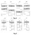
- FIG. 3is a simplified block diagram of pages of memory cells.
- Each blocksuch as each of the blocks 210 - 213 , is further divided into pages of memory cells.
- each block 210 , 211 , 212 , or 213is divided into eight pages P 0 -P 7 .
- the pages within two or more blocksmay be logically linked into metapages.
- a metapagecan be formed of one page, such as P 1 , from each of four blocks 210 - 213 .
- a metapagecan extend across all planes within the non-volatile memory storage system or the non-volatile memory storage system can dynamically form metapages from one or more pages in one or more separate blocks in one or more different planes.
- FIG. 4is a simplified block diagram of sectors of memory cells.
- a pagecan be further divided into one or more sectors.
- the amount of data in each pagecan be an integer number of one or more sectors of data, where each sector may store 512 bytes of data.
- FIG. 4shows page 401 divided into two sectors 402 and 404 .
- Each sector 402 or 404contains data 406 , which can be 512 bytes in size, and overhead data 405 associated with the data.
- the size of overhead data 405can be 16 bytes and can store, for example, an ECC calculated from data 406 during programming, the logical address associated with the data, a count of the number of times the block has been erased and re-programmed, control flags, operating voltage levels, and other information associated with the data.
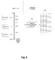
- FIG. 5is a simplified block diagram of a logical interface between a host and non-volatile memory storage system.
- a continuous logical address space 512provides addresses for data that can be stored in memory.
- Logical address space 512 as viewed by the hostcan be divided into increments of clusters of data. Each cluster may include a number of sectors of data, such as between 4 and 64 sectors.
- an application program executed on the hostcreates three data files 1 , 2 , and 3 .
- Files 1 , 2 , and 3can be an ordered set of data and are identified by a unique name or other reference.
- the hostassigns a logical address space to file 1 that is not already allocated to other files.
- file 1is shown to have been assigned a continuous range of available logical addresses.
- hostWhen host creates file 2 after file 1 , the host similarly assigns two different ranges of continuous addresses within logical address space 512 . Host may not assign a continuous logical address to a file, such as file 1 , 2 , or 3 , but can rather assign fragments of logical addresses in between logical address ranges already allocated to other files.
- FIG. 5shows that another file 3 is allocated other portions of logical address space 512 not previously allocated to files 1 and 2 and other data.
- the hostcan keep track of logical address space 512 by maintaining a file allocation table (FAT), where the logical addresses assigned by the host to the various data files, such as files 1 - 3 , by conversion are maintained.
- FATfile allocation table
- the hostreferences files 1 - 3 by their logical addresses and not by the physical locations where the non-volatile memory storage system stores the files.
- the non-volatile memory storage systemreferences files 1 - 3 by portions of the logical addresses to which data have been written and does not reference the files by the logical addresses allocated to the files.
- the non-volatile memory storage systemconverts the logical addresses provided by the host into unique physical addresses within memory cell array 502 where data from the host are stored.
- Block 504represents a table of these logical-to-physical address conversions, which is maintained by the non-volatile memory storage system.
- FIG. 6is a flowchart diagram of a general overview of operations for phased garbage collection, in accordance with an embodiment of the present invention.
- data stored at specific host logical addressescan be overwritten by new data as the original stored data become obsolete.
- the non-volatile memory storage systemin response, writes the new data in an update block and then changes the logical-to-physical address table for those logical addresses to identify the new physical block to which the new data are stored.
- the blocks containing the original data at those logical addressesare then erased and made available for the storage of additional data. Such erasure can take place before a write operation.
- the memory controllerlearns that data at a given logical address have been rendered obsolete or invalid by the host after the new data are written to the same logical address. Many blocks of memory can therefore be storing invalid data for a period of time.
- garbage collectionmay be performed to avoid host timeouts, to avoid performance drops, and to establish a smoother pattern of more frequent but shorter overhead expenditures.
- garbage collectionmay be performed according to a time budget allocated to the data write operation. The budget may be defined by host timeouts, or may be simply to distribute overhead between commands and writes.
- the sizes of blocks and metablocksare increasing and these increases result in a large proportion of individual data writes storing an amount of data that is less than the storage capacity of a metablock, and in many instances, even less than that of a block. Since the non-volatile memory storage system can direct new data to an erased pool metablock, such direction can result in portions of blocks or metablocks being unfilled. If the new data are updates of some data stored in another metablock, remaining valid metapages of data from that other metablock having logical addresses contiguous with those of the new data metapages may be copied in logical address order (or any other order) into the new metablock. The old metablock may retain other valid data metapages. Accordingly, data of certain metapages of an individual metablock can be rendered obsolete or invalid, and replaced by new data with the same logical address being written to a different metablock.
- a garbage collection operationinvolves reading the valid data from one or more blocks (e.g., for original and chaotic updates) and writing the valid data to a new block, ignoring invalid data in the process.
- the non-volatile memory storage systemmay perform the garbage collection operation within a timeout period allocated to a write command. If the garbage collection operation cannot be completed within one timeout period, then the one garbage collection operation may be split into several different phases (or portions), in accordance with an embodiment of the present invention.
- the non-volatile memory storage systemperforms portions of the garbage collection operation using the timeout periods allocated to multiple write commands. In other words, the non-volatile memory storage system utilizes the timeout periods allocated to multiple write commands to perform portions of one garbage collection operation.
- a write command to write new datais received in operation 602 .
- the term “new data”is defined as the data received by the non-volatile memory storage system from a write command to be written to the memory.
- the write commandmay be issued to write a memory write including the new data.
- the write commandis allocated a timeout period to complete the execution of the write command or sector write in a multiple sectors command.
- the timeout periodis a period of time allocated for an execution of the write command.
- An example of a timeout period allocatedis 250 milliseconds.
- the write commandcan be a single sector write command or a multiple sectors write command. In a single sector write command, new data can be written as single sectors to random addresses across a memory. In a multiple sectors write command, multiple sectors of new data having contiguous local addresses are written to the memory and each sector write may have a timeout limit.
- a first phase of the garbage collection operationis performed within the timeout period allocated to the write command.
- the garbage collection operationmay be for the metablock to which the write command is directed, or to another metablock unrelated to the write command.
- the remaining phases of the garbage collectioncan be completed at later timeout periods.
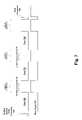
- FIG. 7shows a simplified block diagram of an example of one garbage collection operation split into multiple phases 780 and 781 , in accordance with an embodiment of the invention. As shown in FIG.
- a non-volatile memory storage systemreceives multiple sectors write command 704 and subsequently, multiple sectors of new data 760 - 762 are received for storage into memory.
- Busy signal 702is asserted after each sector of data 760 , 761 , or 762 is received to notify the memory host of the timeout period.
- the non-volatile memory storage systemasserts busy signal 702 to allow the execution of the write command, which may include garbage collection operation (if needed), and other operations.
- a hostdoes not send another command or additional data to the non-volatile memory storage system when busy signal 702 is asserted.
- the non-volatile memory storage systemcan assert busy signal 702 for a limited amount of time after each sector of data 760 , 761 , or 762 is received because the host allows a limited fixed amount of time (i.e., timeout periods 750 - 752 ) for the execution of the write command. If the busy signal remains active for longer than timeout period 750 , 751 , or 752 , the host may repeat the write command or abort the process. Accordingly, the non-volatile memory storage system cannot assert busy signal 702 for more than timeout period 750 , 751 , or 752 . Releasing busy signal 702 after the completion of writing multiple sectors of data 760 - 762 allows the host to communicate further with the non-volatile memory storage system.
- phases 780 and 781 of the garbage collectioncan be allocated between multiple timeout periods 750 - 752 .
- the non-volatile memory storage systemcan utilize each timeout period 750 , 751 , or 752 to perform each phase 780 or 781 of one garbage collection operation.
- first phase 780 of one garbage collectionis performed during first timeout period 750 .
- a portion of valid datacan be copied from one block to another block during first timeout period 750 .
- the previous garbage collection operation started at first timeout periodis continued.
- the non-volatile memory storage systemperforms second phase 781 of the previous garbage collection operation during timeout period 751 until the previous garbage collection is completed.
- the previous garbage collectioncan be completed by copying the remaining or last portion of the valid data from the one block to the other block. If the previous garbage collection operation cannot be completed within second timeout period 751 , then the non-volatile memory storage system can use subsequent timeout periods, such as third timeout period 752 , to complete the garbage collection operation. At the end of multiple sectors write command 704 , the non-volatile memory storage system can assert busy signal 702 after stop command 706 is received or until all sectors of data 760 - 762 are written to the memory cell array.
- the new data received from the write operationcan be stored in a buffer portion of a metablock to which the new data (or memory write) are written in operation 606 .
- the new data from the write commandmay be written to the buffer portion if the new data are being written to the same metablock that is currently being garbage collected. If the new data are written to a different logical group, the new data may be written to another block.
- the new data from the write commandmay be written to the buffer portion of a metablock different from the metablock currently being garbage collected.
- the buffer portionmay be part of a metablock, as described in FIG. 8B .
- FIG. 8Aillustrates a logical group state diagram 800 describing a phased garbage collection using a buffer portion of a metablock according to an embodiment.
- the phased garbage collectionmay be performed by progressing a logical group through several states, including an intact( 1 ) state 802 , an intact( 0 ) state 804 , a sequential update state 806 , a chaotic update state 808 , and a half full state 810 .
- the multiple intact states 802 and 804 , and the half full state 810allow garbage collection to be performed over multiple timeout periods by buffering incoming memory writes.
- there are two phases of garbage collectionthere are two phases of garbage collection; three or more phases of garbage collection may be performed by increasing the number of buffers in the metablock, as is described below.
- logical groupsare described here, it is understood that any memory arrangement may be used. Further, a memory write and garbage collection may be performed without necessarily involving every state 802 - 810 .
- garbage collectionmay be performed when a logical group is updated and the update invalidates portions of the logical group.
- a logical group being updateduses two metablocks, an original block and an update block.
- garbage collection of another logical groupis performed.
- a chaotic update block(e.g., one that includes a logical group that proceeds from the sequential update state 806 to the chaotic update state 808 ) may be compacted 812 , during which garbage collection is performed using a third metablock, and then both the original and chaotic update blocks may be erased.
- the garbage collection processmay be divided into two or more phases to avoid generating timeout errors (i.e., when the time for garbage collection exceeds the timeout period).
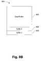
- FIG. 8Billustrates a metablock 820 including a data portion and a buffer portion according to an embodiment.
- the metablock 820may be used as a data storage unit within a memory system as described herein.
- the metablock 820may be used to store data, as well as to buffer memory writes to enable phased garbage collection, as will be explained regarding FIGS. 9 and 10 .
- a logical group 822does not map data storage 1:1 with the metablock 820 .
- the metablock 820includes the logical group (i.e. the data storage portion) 822 , and two buffer portions 824 and 826 .
- the buffer portions 824 and 826may be used to implement phased garbage collection according to various embodiments.
- each of the buffer portions 824 and 826may store a single sector of memory.
- the memory writemay be written to one of the buffer portions 824 or 826 while garbage collection is performed during one or more timeout periods.
- the buffer portions 824 and 826therefore hold incoming memory writes to allow the metablock 820 to be garbage collected without disrupting the incoming writes.
- the buffer portions 824 and 826may be used to hold incoming memory writes while garbage collection is completed for other metablocks. There may be a limit on the number of update blocks; if there are no update blocks available, the buffer portions 824 and 826 can be used to hold incoming writes while waiting for other metablocks to finish garbage collection and make an update block available.
- the buffer portions 824 and 826may be of any desired size.
- One or more buffer portions of the metablock 820may be used to implement phased garbage collection.
- a single buffer portionmay be used to hold a memory write during garbage collection when using a two-phase garbage collection.
- a reserve buffer portione.g., the buffer portion 826
- the metablock 820may also include additional buffer portions to allow for additional phases of garbage collection.
- the metablock 820may include three buffer portions, allowing three phases of garbage collection (two buffer portions to store two memory writes and a reserve buffer portion to account for certain scenarios). Additional buffer portions may be used where the duration of garbage collection may exceed the length of two timeouts. As is explained below, additional states may be added to the state diagram 800 where additional buffer portions and additional phases are used.
- a logical group(e.g., the logical group 822 ) is in the intact( 1 ) state 802 to indicate generally that the buffer portion may still be written to. Specifically, one additional memory write (e.g., a single sector corresponding to the size of the buffer portion 824 or 826 ) may be written to the buffer portion of the metablock (e.g., the metablock 820 ) to which the logical group belongs.
- a logical groupis in the intact( 0 ) state 804 when no more data may be written to the metablock. The logical group progresses from the intact( 1 ) to the intact( 0 ) state when a memory write to fill the buffer portion of the metablock is received.
- a logical groupis in the sequential update state 806 when sequential update data are added to the logical group.
- a sequential update block including the logical group in the sequential update state 806may be allocated from a pool of update blocks and may include a previous single or multiple sectors write.
- the update blockas described above, may be consolidated with an existing (i.e., original) memory block to replace invalid data of the existing memory block with the new data of the update block.
- An intact( 0 ) logical groupmay progress to the sequential update state 806 when a memory write updating the intact( 0 ) logical group is received and a sequential update block is opened.
- the sequential update blockmay be separate from the metablock including the intact( 0 ) logical group (which becomes an “original” block) that is being updated.
- a sequential update blockincludes contiguous update data.
- a chaotic update blocki.e., one with a logical group in the chaotic update state 808 ) includes data that are either not sequential or invalid.
- a sequential update blockmay become chaotic (i.e., a logical group may progress from the sequential update state 806 to the chaotic update state 808 ) if another memory write adding to or invalidating portions of the sequential update block is received.
- the logical group of the chaotic update blockmay be compacted 812 to reclaim obsolete space in the chaotic update block. Compaction 812 may be performed by copying data to a third metablock, but the chaotic update block is eventually erased.
- the chaotic blockmay be consolidated by copying valid data from the original (intact) block and the chaotic update block to a new, third block, the logical group of which proceeds to the half full state 810 , and then to the intact( 1 ) state 802 .
- the chaotic update blockmay replace invalid data with valid data and organize the update data into a sequential fashion.
- a logical group of a metablockmay proceed through either the sequential update state 806 or the chaotic update state 808 , depending on the type of update block that results.
- the logical groupis filled with a combination of data from the update block and the original block until the logical group reaches the half full state 810 .
- the half full state 810describes a state where the logical group includes data written such that the first phase of garbage collection is completed (e.g., the logical group may be half full).
- the logical groupmay not necessarily be half full; any amount of data may be written to the logical group by the half full state 810 .
- the logical groupis fully written, and the logical group is returned to the intact( 1 ) state 802 . After returning to the intact( 1 ) state 802 , the original block is erased and another update block may be initiated.
- the logical group 822proceeds through the various states 802 - 810 in concert with other logical groups.
- a first logical groupe.g., the logical group 822
- another logical groupis simultaneously in the sequential update state 806 or chaotic update state 808 .
- the first logical groupprogresses from the intact( 1 ) state 802 to the intact( 0 ) state 804
- the second logical groupprogresses from either the sequential update state 806 or the chaotic update state 808 to the half full state 810 .
- the intact( 1 ) state 802 and the half full state 810allow garbage collection functions for a memory to be partitioned into multiple phases.
- the intact( 1 ) stateallows the first logical group to wait before proceeding to the sequential update state 806 , which gives the second logical group time to perform garbage collection in two phases. In this way, garbage collection may be divided so that it can be performed during multiple timeout periods.
- FIG. 9Aillustrates a metablock state diagram 900 of a metablock progressing through several states 902 and performing garbage collection according to various embodiments.
- the metablock states 902e.g., intact( 1 ) state 902 d , intact( 0 ) state 902 e
- Transactions 952 between the statesmay not.
- the chaotic update state 902 gproceeds to the erased state 902 a during the transition 952 h
- the chaotic update block state 808proceeds to the half full state 810 .
- the metablock state diagram 900illustrates the progression of a metablock through the several states 902 .
- the metablockmay be referred to using different terms that illustrate the current state of the metablock.
- the metablockis a memory block that begins in an erased block state 902 a and progresses into a sequential update block state 902 b , into which data 904 (e.g., a memory write) are first written. If another memory write 906 is received, the metablock may become a chaotic update block in the chaotic update state 902 g .
- the chaotic update state 902 gmay be compacted in the transition 952 h , and the data written to another metablock.
- the metablockthen continues to an erased state 902 a.
- the valid portions (i.e., the portions not being updated) of the metablock being updated (the original block)are copied into the metablock (i.e., the blocks are garbage collected).
- the metablockmay be said to progress from the sequential update block state 902 b (a block that includes newly written data) to a half full state 902 c .
- the half full state 902 cindicates that the first phase of garbage collection is complete, and that some portion of the logical group of the metablock is full.
- the metablockthen continues to the intact( 1 ) state 902 d , indicating that the logical group of the metablock is full, and that there is one available buffer portion 908 . From there, a memory write 904 to an address 906 (that invalidates the data there) is written to a buffer portion 908 . Once the buffer portion 908 is occupied by the memory write 904 , the metablock moves to the intact( 0 ) state 902 e , indicating that there are no available buffer portions. The metablock then proceeds to an original state 902 f (a block that has invalid data because an update has been received). A new memory write to an address 912 invalidates the data at the address 912 , and may prompt opening a new update block.
- the states 902 h - 902 j and the transitions 952 i - 952 kdescribe a possible worst case scenario for the metablock.
- the metablockmay progress through alternative states 902 - 902 j instead of the states 902 d - 902 f .
- the transition 952 iis the worst case transition between the half full state 902 c and an intact( 1 ) state (here, 902 h ).
- the metablockwhile in the half full state, received a memory write 912 to an address 914 (invalidating the data there) that was buffered in a buffer portion 916 .
- FIG. 9Bgenerally describes a process for garbage collection using an original block and an update block to form an intact block according to an embodiment.
- the diagram 980may be a generalization of garbage collection that occurs within the diagram 900 .
- the process illustrated by FIG. 9Bmay be partitioned into phases to implement phased garbage collection, as is described regarding FIG. 9A .
- an original block 982includes valid data 984 and invalid data 986 .
- An update block 988includes update data 990 .
- the update data 990may be replacing the invalid data 986 .
- the valid data 984 and the update data 990are compacted in the update block 988 .
- the update block 988may be converted into an intact block 992 , and the original block 982 may be erased and reallocated.
- the blocks 982 , 988 , and 990may also include buffer portions to allow phased garbage collection, as is described regarding FIG. 9A .
- FIG. 10is a flowchart describing a process 1000 for performing phased garbage collection according to various embodiments.
- the process 1000describes receiving a memory write to a metablock including a logical group.
- the metablockcould be in one of the states 902 ; the process 1000 determines the state and dictates the appropriate outcome.
- the diagram 900is described in conjunction with the process 1000 .
- the process 1000may include two phases of garbage collection. However, it is understood that additional phases may be performed by implementing modifications described later.
- a memory writeis received.
- the memory writemay be written to an address of a logical group.
- garbage collectionit is determined whether garbage collection has been triggered in operation 1008 . If garbage collection has been triggered, in operation 1010 , one phase of garbage collection (e.g., any phase) for the current logical group is performed. The operation 1010 may advance the update block from the sequential update state 902 b to the half full state 902 c via the transition 952 b . If garbage collection has not been triggered, one phase of garbage collection for another logical group (i.e., other than in the metablock or the update block) is performed in operation 1012 , and the update block may remain in the sequential update state 902 b.
- one phase of garbage collectione.g., any phase
- the operation 1010may advance the update block from the sequential update state 902 b to the half full state 902 c via the transition 952 b . If garbage collection has not been triggered, one phase of garbage collection for another logical group (i.e., other than in the metablock or the update block) is performed in operation 1012 , and the update block may remain
- the process 1000proceeds to operation 1014 .
- operation 1014it is determined the metablock is in the intact( 1 ) state 902 d .
- the logical groupi.e., the data portion
- the memory writemay be written to buffer portion 904 in operation 1016 . Additionally, one phase of garbage collection for another logical group may also be performed.
- the metablockis in the half full state 902 c .
- the half full stateindicates that a first phase of garbage collection has been performed, filling the logical group with an amount of data written during the first phase of garbage collection. Additionally, the memory write may be written to the buffer portion 904 .
- the process 1000may be split into more than two phases.
- a third buffer portionmay be added to the metablock to effect a three-phase garbage collection.
- two buffer portionscould be used where there is no reserve buffer portion.
- an extra intact statee.g., an intact( 2 ) state indicating that there are two remaining buffer portions of the metablock
- an extra half-full statee.g., instead of a half full state, a third-full and two thirds-full states are used
- an intact( 2 ) statemay be added, and a one-third full state and a two-thirds full state may be substituted for the half full state 810 .
- An additional operationmay be added before the operation 1014 , that determines whether the metablock is in an intact( 2 ) state. If the metablock is in an intact( 2 ) state, the memory write is written to a buffer portion and one phase of garbage collection is done for another logical group. If the metablock is not in an intact( 2 ) state, the process 1000 proceeds to the operation 1014 . Additional operations may be added for intact( 3 ) states, intact( 4 ) states, etc. Additional operations may also be added for additional intermediate states (e.g., two-thirds full, three-quarters full).
Landscapes
- Engineering & Computer Science (AREA)
- Theoretical Computer Science (AREA)
- Physics & Mathematics (AREA)
- General Engineering & Computer Science (AREA)
- General Physics & Mathematics (AREA)
- Memory System (AREA)
- Techniques For Improving Reliability Of Storages (AREA)
Abstract
Description
Claims (15)
Priority Applications (3)
| Application Number | Priority Date | Filing Date | Title |
|---|---|---|---|
| US11/540,778US7464216B2 (en) | 2006-09-29 | 2006-09-29 | Method for phased garbage collection with state indicators |
| TW096134956ATWI346286B (en) | 2006-09-29 | 2007-09-19 | Method and non-volatile memory storage system for phased garbage collection |
| PCT/US2007/078817WO2008042592A2 (en) | 2006-09-29 | 2007-09-19 | Phased garbage collection |
Applications Claiming Priority (1)
| Application Number | Priority Date | Filing Date | Title |
|---|---|---|---|
| US11/540,778US7464216B2 (en) | 2006-09-29 | 2006-09-29 | Method for phased garbage collection with state indicators |
Related Child Applications (1)
| Application Number | Title | Priority Date | Filing Date |
|---|---|---|---|
| US12/290,612Continuation-In-PartUS8252019B2 (en) | 2003-01-31 | 2008-10-31 | Filter retrieval catheter system, and methods |
Publications (2)
| Publication Number | Publication Date |
|---|---|
| US20080082596A1 US20080082596A1 (en) | 2008-04-03 |
| US7464216B2true US7464216B2 (en) | 2008-12-09 |
Family
ID=39286562
Family Applications (1)
| Application Number | Title | Priority Date | Filing Date |
|---|---|---|---|
| US11/540,778Active2027-05-12US7464216B2 (en) | 2006-09-29 | 2006-09-29 | Method for phased garbage collection with state indicators |
Country Status (1)
| Country | Link |
|---|---|
| US (1) | US7464216B2 (en) |
Cited By (10)
| Publication number | Priority date | Publication date | Assignee | Title |
|---|---|---|---|---|
| US20080162612A1 (en)* | 2006-12-28 | 2008-07-03 | Andrew Tomlin | Method for block relinking |
| US20080162787A1 (en)* | 2006-12-28 | 2008-07-03 | Andrew Tomlin | System for block relinking |
| US20090089482A1 (en)* | 2007-09-28 | 2009-04-02 | Shai Traister | Dynamic metablocks |
| US20090204824A1 (en)* | 2007-12-31 | 2009-08-13 | Lin Jason T | System, method and memory device providing data scrambling compatible with on-chip copy operation |
| US20090282267A1 (en)* | 2008-05-09 | 2009-11-12 | Ori Stern | Partial scrambling to reduce correlation |
| US20110198455A1 (en)* | 2008-11-06 | 2011-08-18 | Paul Innocenti | Removable strap mounted instrument stand |
| WO2011162973A1 (en) | 2010-06-23 | 2011-12-29 | Sandisk Technologies Inc. | Use of guard bands and phased maintenance operations to avoid exceeding maximum latency requirements in non-volatile memory systems |
| US8543757B2 (en) | 2010-06-23 | 2013-09-24 | Sandisk Technologies Inc. | Techniques of maintaining logical to physical mapping information in non-volatile memory systems |
| US20170031607A1 (en)* | 2010-09-21 | 2017-02-02 | Western Digital Technologies, Inc. | System and method for managing access requests to a memory storage subsystem |
| USRE49133E1 (en)* | 2014-05-27 | 2022-07-12 | Kioxia Corporation | Host-controlled garbage collection |
Families Citing this family (85)
| Publication number | Priority date | Publication date | Assignee | Title |
|---|---|---|---|---|
| US7444461B2 (en)* | 2006-08-04 | 2008-10-28 | Sandisk Corporation | Methods for phased garbage collection |
| US7451265B2 (en)* | 2006-08-04 | 2008-11-11 | Sandisk Corporation | Non-volatile memory storage systems for phased garbage collection |
| US7444462B2 (en)* | 2006-09-28 | 2008-10-28 | Sandisk Corporation | Methods for phased garbage collection using phased garbage collection block or scratch pad block as a buffer |
| US7441071B2 (en)* | 2006-09-28 | 2008-10-21 | Sandisk Corporation | Memory systems for phased garbage collection using phased garbage collection block or scratch pad block as a buffer |
| US7444463B2 (en)* | 2006-09-29 | 2008-10-28 | Sandisk Corporation | System for phased garbage collection with state indicators |
| US8880775B2 (en)* | 2008-06-20 | 2014-11-04 | Seagate Technology Llc | System and method of garbage collection in a memory device |
| US8572311B1 (en) | 2010-01-11 | 2013-10-29 | Apple Inc. | Redundant data storage in multi-die memory systems |
| US9652376B2 (en)* | 2013-01-28 | 2017-05-16 | Radian Memory Systems, Inc. | Cooperative flash memory control |
| US11249652B1 (en) | 2013-01-28 | 2022-02-15 | Radian Memory Systems, Inc. | Maintenance of nonvolatile memory on host selected namespaces by a common memory controller |
| US10445229B1 (en) | 2013-01-28 | 2019-10-15 | Radian Memory Systems, Inc. | Memory controller with at least one address segment defined for which data is striped across flash memory dies, with a common address offset being used to obtain physical addresses for the data in each of the dies |
| US10642505B1 (en) | 2013-01-28 | 2020-05-05 | Radian Memory Systems, Inc. | Techniques for data migration based on per-data metrics and memory degradation |
| US10552085B1 (en) | 2014-09-09 | 2020-02-04 | Radian Memory Systems, Inc. | Techniques for directed data migration |
| US9542118B1 (en) | 2014-09-09 | 2017-01-10 | Radian Memory Systems, Inc. | Expositive flash memory control |
| CN105701021B (en)* | 2014-12-10 | 2021-03-02 | 慧荣科技股份有限公司 | Data storage device and data writing method thereof |
| US10552058B1 (en) | 2015-07-17 | 2020-02-04 | Radian Memory Systems, Inc. | Techniques for delegating data processing to a cooperative memory controller |
| US9916238B2 (en)* | 2015-08-25 | 2018-03-13 | Sandisk Technologies Llc | Memory system and method for performing garbage collection on blocks based on their obsolescence patterns |
| KR20170044780A (en)* | 2015-10-15 | 2017-04-26 | 에스케이하이닉스 주식회사 | Memory system and operating method for the same |
| JP2018041154A (en)* | 2016-09-05 | 2018-03-15 | 東芝メモリ株式会社 | Storage system and processing method |
| US11074018B2 (en)* | 2017-04-06 | 2021-07-27 | International Business Machines Corporation | Network asset management |
| US11893265B2 (en)* | 2017-05-02 | 2024-02-06 | Google Llc | Garbage collection for data storage |
| US10901892B2 (en)* | 2017-05-18 | 2021-01-26 | Western Digital Technologies, Inc. | Locality grouping during garbage collection with flush of buffered write data upon completion of garbage collection operation |
| US10740228B2 (en)* | 2017-05-18 | 2020-08-11 | Sandisk Technologies Llc | Locality grouping during garbage collection of a storage device |
| US12260109B2 (en) | 2017-06-06 | 2025-03-25 | Google Llc | Optimizing data storage with access windows |
| US20190163370A1 (en)* | 2017-11-28 | 2019-05-30 | International Business Machines Corporation | Data replication based on data-driven recovery objectives |
| KR20190100782A (en)* | 2018-02-21 | 2019-08-29 | 에스케이하이닉스 주식회사 | Storage device and operating method thereof |
| US20210224001A1 (en)* | 2018-08-30 | 2021-07-22 | Sony Corporation | Storage controller, storage system, and information processing system |
| EP3866016B1 (en)* | 2018-11-20 | 2025-01-08 | Huawei Technologies Co., Ltd. | Method and apparatus for deleting index entry in memory |
| US10976950B1 (en)* | 2019-01-15 | 2021-04-13 | Twitter, Inc. | Distributed dataset modification, retention, and replication |
| US11113270B2 (en) | 2019-01-24 | 2021-09-07 | EMC IP Holding Company LLC | Storing a non-ordered associative array of pairs using an append-only storage medium |
| KR102744552B1 (en)* | 2019-04-11 | 2024-12-19 | 에스케이하이닉스 주식회사 | Data Storage Device, Operation Method Thereof |
| TWI790383B (en)* | 2019-06-19 | 2023-01-21 | 慧榮科技股份有限公司 | A data storage device and a data processing method |
| EP3993273A4 (en)* | 2019-07-22 | 2022-07-27 | Huawei Technologies Co., Ltd. | METHOD AND DEVICE FOR DATA COMPRESSION IN A STORAGE SYSTEM, DEVICE AND READABLE STORAGE MEDIUM |
| KR20210051873A (en)* | 2019-10-31 | 2021-05-10 | 에스케이하이닉스 주식회사 | Controller and memory system |
| US11175984B1 (en) | 2019-12-09 | 2021-11-16 | Radian Memory Systems, Inc. | Erasure coding techniques for flash memory |
| JP2021099642A (en)* | 2019-12-20 | 2021-07-01 | キヤノン株式会社 | Information processing device and method for controlling information processing device |
| US11604759B2 (en) | 2020-05-01 | 2023-03-14 | EMC IP Holding Company LLC | Retention management for data streams |
| US11599546B2 (en) | 2020-05-01 | 2023-03-07 | EMC IP Holding Company LLC | Stream browser for data streams |
| US11599420B2 (en) | 2020-07-30 | 2023-03-07 | EMC IP Holding Company LLC | Ordered event stream event retention |
| US11567665B2 (en)* | 2020-08-31 | 2023-01-31 | Micron Technology, Inc. | Data dispersion-based memory management |
| US11513871B2 (en) | 2020-09-30 | 2022-11-29 | EMC IP Holding Company LLC | Employing triggered retention in an ordered event stream storage system |
| US11755555B2 (en) | 2020-10-06 | 2023-09-12 | EMC IP Holding Company LLC | Storing an ordered associative array of pairs using an append-only storage medium |
| US11599293B2 (en) | 2020-10-14 | 2023-03-07 | EMC IP Holding Company LLC | Consistent data stream replication and reconstruction in a streaming data storage platform |
| KR20220060385A (en)* | 2020-11-04 | 2022-05-11 | 에스케이하이닉스 주식회사 | Storage device and operating method thereof |
| US11494111B2 (en)* | 2020-12-17 | 2022-11-08 | Micron Technology, Inc. | Data operation based on valid memory unit count |
| US11556270B2 (en)* | 2021-01-07 | 2023-01-17 | EMC IP Holding Company LLC | Leveraging garbage collection for raid transformation |
| US11816065B2 (en) | 2021-01-11 | 2023-11-14 | EMC IP Holding Company LLC | Event level retention management for data streams |
| US20220222008A1 (en)* | 2021-01-14 | 2022-07-14 | Silicon Motion, Inc. | Method for managing flash memory module and associated flash memory controller and memory device |
| US12099513B2 (en) | 2021-01-19 | 2024-09-24 | EMC IP Holding Company LLC | Ordered event stream event annulment in an ordered event stream storage system |
| TWI766582B (en)* | 2021-02-17 | 2022-06-01 | 群聯電子股份有限公司 | Valid data merging method, memory storage device and memory control circuit unit |
| US12099742B2 (en)* | 2021-03-15 | 2024-09-24 | Pure Storage, Inc. | Utilizing programming page size granularity to optimize data segment storage in a storage system |
| US11775197B2 (en)* | 2021-03-25 | 2023-10-03 | Kyocera Document Solutions Inc. | Single command for reading then clearing dynamic random access memory |
| US11740828B2 (en)* | 2021-04-06 | 2023-08-29 | EMC IP Holding Company LLC | Data expiration for stream storages |
| US12001881B2 (en) | 2021-04-12 | 2024-06-04 | EMC IP Holding Company LLC | Event prioritization for an ordered event stream |
| US11740821B2 (en)* | 2021-04-12 | 2023-08-29 | EMC IP Holding Company LLC | Cost-aware garbage collection for cloud storage |
| US11954537B2 (en) | 2021-04-22 | 2024-04-09 | EMC IP Holding Company LLC | Information-unit based scaling of an ordered event stream |
| US11681460B2 (en) | 2021-06-03 | 2023-06-20 | EMC IP Holding Company LLC | Scaling of an ordered event stream based on a writer group characteristic |
| US11513720B1 (en)* | 2021-06-11 | 2022-11-29 | Western Digital Technologies, Inc. | Data storage device having predictive analytics |
| US11543993B1 (en)* | 2021-06-17 | 2023-01-03 | Western Digital Technologies, Inc. | Fast garbage collection in zoned namespaces SSDs |
| US11735282B2 (en) | 2021-07-22 | 2023-08-22 | EMC IP Holding Company LLC | Test data verification for an ordered event stream storage system |
| US11733893B2 (en)* | 2021-07-28 | 2023-08-22 | International Business Machines Corporation | Management of flash storage media |
| US11907564B2 (en)* | 2021-08-03 | 2024-02-20 | Yadro International Ltd. | Method of and system for initiating garbage collection requests |
| US12073113B2 (en)* | 2021-08-30 | 2024-08-27 | Micron Technology, Inc. | Direct logical-to-physical address mapping for sequential physical addresses |
| US11922047B2 (en)* | 2021-09-16 | 2024-03-05 | EMC IP Holding Company LLC | Using RPO as an optimization target for DataDomain garbage collection |
| JP2023044330A (en)* | 2021-09-17 | 2023-03-30 | キオクシア株式会社 | Memory system and control method |
| US11599298B1 (en)* | 2021-09-23 | 2023-03-07 | Western Digital Technologies, Inc. | Storage system and method for prediction-based pre-erase of blocks to improve sequential performance |
| US11847334B2 (en)* | 2021-09-23 | 2023-12-19 | EMC IP Holding Company LLC | Method or apparatus to integrate physical file verification and garbage collection (GC) by tracking special segments |
| US11971850B2 (en) | 2021-10-15 | 2024-04-30 | EMC IP Holding Company LLC | Demoted data retention via a tiered ordered event stream data storage system |
| US12124727B2 (en)* | 2021-12-17 | 2024-10-22 | Samsung Electronics Co., Ltd. | Automatic deletion in a persistent storage device |
| EP4446863A4 (en)* | 2021-12-29 | 2025-03-12 | Huawei Technologies Co., Ltd. | METHOD AND APPARATUS FOR GENERATING BLOCK GROUP, AND DEVICE |
| US12019899B2 (en)* | 2022-03-03 | 2024-06-25 | Western Digital Technologies, Inc. | Data relocation with protection for open relocation destination blocks |
| US11886735B2 (en)* | 2022-03-22 | 2024-01-30 | Micron Technology, Inc. | Data movement based on address table activity |
| US11941297B2 (en) | 2022-04-11 | 2024-03-26 | Netapp, Inc. | Garbage collection and bin synchronization for distributed storage architecture |
| US11934656B2 (en)* | 2022-04-11 | 2024-03-19 | Netapp, Inc. | Garbage collection and bin synchronization for distributed storage architecture |
| US11947452B2 (en) | 2022-06-01 | 2024-04-02 | Micron Technology, Inc. | Controlling variation of valid data counts in garbage collection source blocks |
| US12293077B2 (en)* | 2022-07-06 | 2025-05-06 | Samsung Electronics Co., Ltd. | Systems, methods, and devices for using a reclaim unit based on a reference update in a storage device |
| US20240012579A1 (en)* | 2022-07-06 | 2024-01-11 | Samsung Electronics Co., Ltd. | Systems, methods, and apparatus for data placement in a storage device |
| US12242751B2 (en)* | 2023-03-03 | 2025-03-04 | SanDisk Technologies, Inc. | Data storage device and method for host-assisted efficient handling of multiple versions of data |
| KR20240138839A (en)* | 2023-03-13 | 2024-09-20 | 삼성전자주식회사 | Memory device, operating method of memory device and memory system |
| TWI859965B (en)* | 2023-07-11 | 2024-10-21 | 群聯電子股份有限公司 | Memory management method, memory storage device and memory control circuit unit |
| US20250028473A1 (en)* | 2023-07-18 | 2025-01-23 | SK Hynix NAND Product Solutions Corp. (dba Solidigm) | System and methods for dram-less garbage collection with improved performance |
| US20250053346A1 (en)* | 2023-08-07 | 2025-02-13 | Dell Products L.P. | Efficient ingest tier references via virtual addresses |
| CN117891408A (en)* | 2024-01-26 | 2024-04-16 | 三星(中国)半导体有限公司 | Method for deduplicating data of storage device and storage device |
| CN120429244A (en)* | 2024-02-02 | 2025-08-05 | 慧荣科技股份有限公司 | Garbage collection method in flash memory device, computer readable storage medium and device |
| US12306750B1 (en)* | 2024-02-22 | 2025-05-20 | Oracle International Corporation | Selecting garbage collection processes |
| US12399820B1 (en) | 2024-02-22 | 2025-08-26 | Oracle International Corporation | Selecting garbage collection processes |
Citations (17)
| Publication number | Priority date | Publication date | Assignee | Title |
|---|---|---|---|---|
| US5640529A (en) | 1993-07-29 | 1997-06-17 | Intel Corporation | Method and system for performing clean-up of a solid state disk during host command execution |
| US20010023472A1 (en) | 1997-10-21 | 2001-09-20 | Noriko Kubushiro | Data storage control method and apparatus for external storage device using a plurality of flash memories |
| US6510440B1 (en) | 2000-01-10 | 2003-01-21 | International Business Machines Corporation | Method and apparatus for performing generational garbage collection using barrier bits |
| US6792601B1 (en) | 2000-05-18 | 2004-09-14 | International Business Machines Corporation | Multiple mode object locking method and system |
| WO2005045683A1 (en) | 2003-11-05 | 2005-05-19 | Electronics And Telecommunications Research Institute | Apparatus and method for garbage collection |
| US20050141312A1 (en) | 2003-12-30 | 2005-06-30 | Sinclair Alan W. | Non-volatile memory and method with non-sequential update block management |
| WO2006065655A1 (en) | 2004-12-16 | 2006-06-22 | Sandisk Corporation | Non-volatile memory and method with improved indexing for scratch pad and update blocks |
| US20060161724A1 (en) | 2005-01-20 | 2006-07-20 | Bennett Alan D | Scheduling of housekeeping operations in flash memory systems |
| US20060161728A1 (en) | 2005-01-20 | 2006-07-20 | Bennett Alan D | Scheduling of housekeeping operations in flash memory systems |
| US7114045B1 (en) | 2003-12-23 | 2006-09-26 | Sun Microsystems, Inc. | Garbage collection with a dynamic window |
| US20070033324A1 (en) | 2005-08-03 | 2007-02-08 | Sinclair Alan W | Scheduling of reclaim operations in non-volatile memory |
| US7287049B1 (en) | 2004-06-29 | 2007-10-23 | Sun Microsystems, Inc. | Tracking minimum mutator utilization (MMU) constraints in a garbage-collection system |
| US20080034175A1 (en) | 2006-08-04 | 2008-02-07 | Shai Traister | Methods for phased garbage collection |
| US20080034174A1 (en) | 2006-08-04 | 2008-02-07 | Shai Traister | Non-volatile memory storage systems for phased garbage collection |
| US20080082728A1 (en) | 2006-09-28 | 2008-04-03 | Shai Traister | Memory systems for phased garbage collection using phased garbage collection block or scratch pad block as a buffer |
| US20080082775A1 (en) | 2006-09-29 | 2008-04-03 | Sergey Anatolievich Gorobets | System for phased garbage collection |
| US20080086619A1 (en) | 2006-09-28 | 2008-04-10 | Shai Traister | Methods for phased garbage collection using phased garbage collection block or scratch pad block as a buffer |
- 2006
- 2006-09-29USUS11/540,778patent/US7464216B2/enactiveActive
Patent Citations (18)
| Publication number | Priority date | Publication date | Assignee | Title |
|---|---|---|---|---|
| US5640529A (en) | 1993-07-29 | 1997-06-17 | Intel Corporation | Method and system for performing clean-up of a solid state disk during host command execution |
| US20010023472A1 (en) | 1997-10-21 | 2001-09-20 | Noriko Kubushiro | Data storage control method and apparatus for external storage device using a plurality of flash memories |
| US6510440B1 (en) | 2000-01-10 | 2003-01-21 | International Business Machines Corporation | Method and apparatus for performing generational garbage collection using barrier bits |
| US6792601B1 (en) | 2000-05-18 | 2004-09-14 | International Business Machines Corporation | Multiple mode object locking method and system |
| WO2005045683A1 (en) | 2003-11-05 | 2005-05-19 | Electronics And Telecommunications Research Institute | Apparatus and method for garbage collection |
| US7114045B1 (en) | 2003-12-23 | 2006-09-26 | Sun Microsystems, Inc. | Garbage collection with a dynamic window |
| US20050141312A1 (en) | 2003-12-30 | 2005-06-30 | Sinclair Alan W. | Non-volatile memory and method with non-sequential update block management |
| US7287049B1 (en) | 2004-06-29 | 2007-10-23 | Sun Microsystems, Inc. | Tracking minimum mutator utilization (MMU) constraints in a garbage-collection system |
| WO2006065655A1 (en) | 2004-12-16 | 2006-06-22 | Sandisk Corporation | Non-volatile memory and method with improved indexing for scratch pad and update blocks |
| US20060161728A1 (en) | 2005-01-20 | 2006-07-20 | Bennett Alan D | Scheduling of housekeeping operations in flash memory systems |
| US20060161724A1 (en) | 2005-01-20 | 2006-07-20 | Bennett Alan D | Scheduling of housekeeping operations in flash memory systems |
| US20080091872A1 (en) | 2005-01-20 | 2008-04-17 | Bennett Alan D | Scheduling of Housekeeping Operations in Flash Memory Systems |
| US20070033324A1 (en) | 2005-08-03 | 2007-02-08 | Sinclair Alan W | Scheduling of reclaim operations in non-volatile memory |
| US20080034175A1 (en) | 2006-08-04 | 2008-02-07 | Shai Traister | Methods for phased garbage collection |
| US20080034174A1 (en) | 2006-08-04 | 2008-02-07 | Shai Traister | Non-volatile memory storage systems for phased garbage collection |
| US20080082728A1 (en) | 2006-09-28 | 2008-04-03 | Shai Traister | Memory systems for phased garbage collection using phased garbage collection block or scratch pad block as a buffer |
| US20080086619A1 (en) | 2006-09-28 | 2008-04-10 | Shai Traister | Methods for phased garbage collection using phased garbage collection block or scratch pad block as a buffer |
| US20080082775A1 (en) | 2006-09-29 | 2008-04-03 | Sergey Anatolievich Gorobets | System for phased garbage collection |
Non-Patent Citations (6)
| Title |
|---|
| ISA International Search Report and Written Opinion dated Apr. 24, 2008 in related International Application No. PCT/US2007/0078817 (14 pages). |
| USPTO Notice of Allowance and Fee(s) Due mailed Aug. 8, 2008 in U.S. Appl. No. 11/541,371 (SNDKP544A). |
| USPTO Notice of Allowance and Fee(s) Due mailed Jul. 1, 2008, 2008 in U.S. Appl. No. 11/499,606 (SNDKP543). |
| USPTO Notice of Allowance and Fee(s) Due mailed Jul. 16, 2008 in U.S. Appl. No. 11/541,012 (SNDKP551A). |
| USPTO Notice of Allowance and Fee(s) Due mailed Jul. 17, 2008 in U.S. Appl. No. 11/541,035 (SNDKP551). |
| USPTO Notice of Allowance and Fee(s) Due mailed Jun. 23, 2008, 2008 in U.S. Appl. No. 11/499,598 (SNDKP543A). |
Cited By (19)
| Publication number | Priority date | Publication date | Assignee | Title |
|---|---|---|---|---|
| US20080162787A1 (en)* | 2006-12-28 | 2008-07-03 | Andrew Tomlin | System for block relinking |
| US20080162612A1 (en)* | 2006-12-28 | 2008-07-03 | Andrew Tomlin | Method for block relinking |
| US20090089482A1 (en)* | 2007-09-28 | 2009-04-02 | Shai Traister | Dynamic metablocks |
| US8566504B2 (en) | 2007-09-28 | 2013-10-22 | Sandisk Technologies Inc. | Dynamic metablocks |
| US8301912B2 (en) | 2007-12-31 | 2012-10-30 | Sandisk Technologies Inc. | System, method and memory device providing data scrambling compatible with on-chip copy operation |
| US20090204824A1 (en)* | 2007-12-31 | 2009-08-13 | Lin Jason T | System, method and memory device providing data scrambling compatible with on-chip copy operation |
| USRE45697E1 (en) | 2007-12-31 | 2015-09-29 | Sandisk Technologies Inc. | System, method and memory device providing data scrambling compatible with on-chip copy operation |
| US20090282267A1 (en)* | 2008-05-09 | 2009-11-12 | Ori Stern | Partial scrambling to reduce correlation |
| US8059455B2 (en) | 2008-05-09 | 2011-11-15 | Sandisk Il Ltd. | Partial scrambling to reduce correlation |
| US20090279362A1 (en)* | 2008-05-09 | 2009-11-12 | Ori Stern | Partial scrambling to reduce correlation |
| US20110198455A1 (en)* | 2008-11-06 | 2011-08-18 | Paul Innocenti | Removable strap mounted instrument stand |
| US8637752B2 (en)* | 2008-11-06 | 2014-01-28 | Paul Innocenti | Removable strap mounted instrument stand |
| WO2011162973A1 (en) | 2010-06-23 | 2011-12-29 | Sandisk Technologies Inc. | Use of guard bands and phased maintenance operations to avoid exceeding maximum latency requirements in non-volatile memory systems |
| US8417876B2 (en) | 2010-06-23 | 2013-04-09 | Sandisk Technologies Inc. | Use of guard bands and phased maintenance operations to avoid exceeding maximum latency requirements in non-volatile memory systems |
| US8543757B2 (en) | 2010-06-23 | 2013-09-24 | Sandisk Technologies Inc. | Techniques of maintaining logical to physical mapping information in non-volatile memory systems |
| US20170031607A1 (en)* | 2010-09-21 | 2017-02-02 | Western Digital Technologies, Inc. | System and method for managing access requests to a memory storage subsystem |
| US10048875B2 (en)* | 2010-09-21 | 2018-08-14 | Western Digital Technologies, Inc. | System and method for managing access requests to a memory storage subsystem |
| USRE49133E1 (en)* | 2014-05-27 | 2022-07-12 | Kioxia Corporation | Host-controlled garbage collection |
| USRE49162E1 (en)* | 2014-05-27 | 2022-08-09 | Kioxia Corporation | Host-controlled garbage collection |
Also Published As
| Publication number | Publication date |
|---|---|
| US20080082596A1 (en) | 2008-04-03 |
Similar Documents
| Publication | Publication Date | Title |
|---|---|---|
| US7464216B2 (en) | Method for phased garbage collection with state indicators | |
| US7444463B2 (en) | System for phased garbage collection with state indicators | |
| US7441071B2 (en) | Memory systems for phased garbage collection using phased garbage collection block or scratch pad block as a buffer | |
| US7444462B2 (en) | Methods for phased garbage collection using phased garbage collection block or scratch pad block as a buffer | |
| US7451265B2 (en) | Non-volatile memory storage systems for phased garbage collection | |
| US7444461B2 (en) | Methods for phased garbage collection | |
| US7987332B2 (en) | Methods for storing memory operations in a queue | |
| US20080162787A1 (en) | System for block relinking | |
| US20080235480A1 (en) | Systems for storing memory operations in a queue | |
| JP4362549B1 (en) | Gradual garbage collection | |
| US10120613B2 (en) | System and method for rescheduling host and maintenance operations in a non-volatile memory | |
| US10133490B2 (en) | System and method for managing extended maintenance scheduling in a non-volatile memory | |
| US20080235489A1 (en) | Systems for forcing an update block to remain sequential | |
| US8341375B2 (en) | Methods for conversion of update blocks based on association with host file management data structures | |
| JP2021128582A (en) | Memory system and control method | |
| US20100082917A1 (en) | Solid state storage system and method of controlling solid state storage system using a multi-plane method and an interleaving method | |
| US20170123666A1 (en) | System and method for managing maintenance scheduling in a non-volatile memory | |
| US20080162612A1 (en) | Method for block relinking | |
| US10042553B2 (en) | Method and system for programming a multi-layer non-volatile memory having a single fold data path | |
| US7904670B2 (en) | Methods for conversion of update blocks based on comparison with a threshold size | |
| US20080235464A1 (en) | System for conversion of update blocks based on comparison with a threshold size | |
| TWI380303B (en) | Methods for storing memory operations in a queue | |
| US20080235465A1 (en) | Systems for conversion of update blocks based on association with host file management data structures | |
| US8275953B2 (en) | Methods for forcing an update block to remain sequential | |
| WO2008042596A2 (en) | Memory systems for phased garbage collection using phased garbage collection block or scratch pad block as a buffer |
Legal Events
| Date | Code | Title | Description |
|---|---|---|---|
| AS | Assignment | Owner name:SANDISK CORPORATION, CALIFORNIA Free format text:ASSIGNMENT OF ASSIGNORS INTEREST;ASSIGNOR:GOROBETS, SERGEY ANATOLIEVICH;REEL/FRAME:018660/0449 Effective date:20060929 | |
| STCF | Information on status: patent grant | Free format text:PATENTED CASE | |
| AS | Assignment | Owner name:SANDISK TECHNOLOGIES INC., TEXAS Free format text:ASSIGNMENT OF ASSIGNORS INTEREST;ASSIGNOR:SANDISK CORPORATION;REEL/FRAME:026381/0835 Effective date:20110404 | |
| FPAY | Fee payment | Year of fee payment:4 | |
| AS | Assignment | Owner name:SANDISK TECHNOLOGIES LLC, TEXAS Free format text:CHANGE OF NAME;ASSIGNOR:SANDISK TECHNOLOGIES INC;REEL/FRAME:038809/0472 Effective date:20160516 | |
| FPAY | Fee payment | Year of fee payment:8 | |
| MAFP | Maintenance fee payment | Free format text:PAYMENT OF MAINTENANCE FEE, 12TH YEAR, LARGE ENTITY (ORIGINAL EVENT CODE: M1553); ENTITY STATUS OF PATENT OWNER: LARGE ENTITY Year of fee payment:12 | |
| AS | Assignment | Owner name:SANDISK TECHNOLOGIES, INC., CALIFORNIA Free format text:ASSIGNMENT OF ASSIGNORS INTEREST;ASSIGNOR:SANDISK TECHNOLOGIES LLC;REEL/FRAME:069796/0423 Effective date:20241227 | |
| AS | Assignment | Owner name:SANDISK TECHNOLOGIES, INC., CALIFORNIA Free format text:PARTIAL RELEASE OF SECURITY INTERESTS;ASSIGNOR:JPMORGAN CHASE BANK, N.A., AS AGENT;REEL/FRAME:071382/0001 Effective date:20250424 Owner name:JPMORGAN CHASE BANK, N.A., AS COLLATERAL AGENT, ILLINOIS Free format text:SECURITY AGREEMENT;ASSIGNOR:SANDISK TECHNOLOGIES, INC.;REEL/FRAME:071050/0001 Effective date:20250424 |