US7463702B2 - System and method for one-pass blind transport format detection - Google Patents
System and method for one-pass blind transport format detectionDownload PDFInfo
- Publication number
- US7463702B2 US7463702B2US10/292,268US29226802AUS7463702B2US 7463702 B2US7463702 B2US 7463702B2US 29226802 AUS29226802 AUS 29226802AUS 7463702 B2US7463702 B2US 7463702B2
- Authority
- US
- United States
- Prior art keywords
- btfd
- traceback
- recited
- point
- viterbi
- Prior art date
- Legal status (The legal status is an assumption and is not a legal conclusion. Google has not performed a legal analysis and makes no representation as to the accuracy of the status listed.)
- Expired - Fee Related, expires
Links
- 238000000034methodMethods0.000titleclaimsabstractdescription35
- 238000001514detection methodMethods0.000titleclaimsabstractdescription9
- 230000001419dependent effectEffects0.000claimsabstractdescription6
- 230000005540biological transmissionEffects0.000claimsdescription17
- 238000006243chemical reactionMethods0.000claimsdescription2
- 238000012545processingMethods0.000description17
- 238000010586diagramMethods0.000description15
- 230000006870functionEffects0.000description12
- 238000012360testing methodMethods0.000description9
- 238000004891communicationMethods0.000description5
- 238000005516engineering processMethods0.000description3
- ZIIRLFNUZROIBX-UHFFFAOYSA-N2,3,5-trichlorobenzene-1,4-diolChemical compoundOC1=CC(Cl)=C(O)C(Cl)=C1ClZIIRLFNUZROIBX-UHFFFAOYSA-N0.000description2
- 238000004364calculation methodMethods0.000description2
- 230000001413cellular effectEffects0.000description2
- 239000002131composite materialSubstances0.000description2
- 230000003247decreasing effectEffects0.000description2
- 238000005265energy consumptionMethods0.000description2
- 238000011010flushing procedureMethods0.000description2
- 238000003780insertionMethods0.000description2
- 230000037431insertionEffects0.000description2
- 238000012804iterative processMethods0.000description2
- 238000010606normalizationMethods0.000description2
- 230000035945sensitivityEffects0.000description2
- 238000001228spectrumMethods0.000description2
- 230000004075alterationEffects0.000description1
- 230000000295complement effectEffects0.000description1
- 238000010276constructionMethods0.000description1
- 125000004122cyclic groupChemical group0.000description1
- 230000007812deficiencyEffects0.000description1
- 238000011156evaluationMethods0.000description1
- 230000000977initiatory effectEffects0.000description1
- 238000006467substitution reactionMethods0.000description1
- 208000037918transfusion-transmitted diseaseDiseases0.000description1
Images


Classifications
- H—ELECTRICITY
- H04—ELECTRIC COMMUNICATION TECHNIQUE
- H04L—TRANSMISSION OF DIGITAL INFORMATION, e.g. TELEGRAPHIC COMMUNICATION
- H04L1/00—Arrangements for detecting or preventing errors in the information received
- H04L1/004—Arrangements for detecting or preventing errors in the information received by using forward error control
- H04L1/0045—Arrangements at the receiver end
- H04L1/0046—Code rate detection or code type detection
- H—ELECTRICITY
- H04—ELECTRIC COMMUNICATION TECHNIQUE
- H04L—TRANSMISSION OF DIGITAL INFORMATION, e.g. TELEGRAPHIC COMMUNICATION
- H04L1/00—Arrangements for detecting or preventing errors in the information received
- H04L1/004—Arrangements for detecting or preventing errors in the information received by using forward error control
- H04L1/0045—Arrangements at the receiver end
- H04L1/0054—Maximum-likelihood or sequential decoding, e.g. Viterbi, Fano, ZJ algorithms
- H—ELECTRICITY
- H04—ELECTRIC COMMUNICATION TECHNIQUE
- H04B—TRANSMISSION
- H04B1/00—Details of transmission systems, not covered by a single one of groups H04B3/00 - H04B13/00; Details of transmission systems not characterised by the medium used for transmission
- H04B1/69—Spread spectrum techniques
- H04B1/707—Spread spectrum techniques using direct sequence modulation
Definitions
- the present inventionis directed, in general, to code-division multiple access (CDMA) communication systems and, more specifically, to a system and method for one-pass blind transport format detection (BTFD) for use in a CDMA receiver.
- CDMAcode-division multiple access
- BTFDblind transport format detection
- Wireless communicationis playing an evermore important role in today's world. More people are signing up for wireless service, and they are expecting their wireless terminals (e.g., pagers, phones, faxes and computers) to perform more functions more rapidly and efficiently than ever before.
- wireless terminalse.g., pagers, phones, faxes and computers
- UMTSUniversal Mobile Telecommunications System
- WCDMAWideband Code-Division Multiple Access
- 5 Mhz carrier bandwidthcan accommodate very high data communication speeds and therefore the speed, flexibility and features that people are beginning to demand.
- a CDMA systemmay be designed to support one or more CDMA standards such as (1) the “TIA/EIA-95-B Mobile Station-Base Station Compatibility Standard for Dual-Mode Wideband Spread Spectrum Cellular System” (the IS-95 standard), (2) the “TIA/EIA-98-D Recommended Minimum Standard for Dual-Mode Wideband Spread Spectrum Cellular Mobile Station” (the IS-98 standard), (3) the standard offered by a consortium named “3 rd Generation Partnership Project” (3GPP) and embodied in a set of documents including Document Nos.
- CDMA standardssuch as (1) the “TIA/EIA-95-B Mobile Station-Base Station Compatibility Standard for Dual-Mode Wideband Spread Spectrum Cellular System” (the IS-95 standard), (2) the “TIA/EIA-98-D Recommended Minimum Standard for Dual-Mode Wideband Spread Spectrum Cellular Mobile Station” (the IS-98 standard), (3) the standard offered by a consortium named “3 rd Generation Partnership Project” (3GPP) and embodied in a set of documents including
- 3G TS 25.211, 3G TS 25.212, 3G TS 25.213 and 3G TS 25.214(the WCDMA standard) and (4) the standard offered by a consortium named “3 rd Generation Partnership Project 2” (3GPP2) and embodied in a set of documents that includes Nos. C.S0002-A, C.S0005-A, C.S0010-A, C.S0011-A, C.S0024 and C.S0026 (the CDMA2000 standard). These standards are incorporated herein by reference.
- WCDMAcan support more than one overlying transport format.
- UMTScurrently supports 16 such transport formats for WCDMA.
- Each formatcalls for bits of information transmitted between stations to be gathered into frames and given Cyclic Redundancy Check (CRC) bits to ensure their integrity.
- CRCCyclic Redundancy Check
- the similarity between the various transport formatsends there.
- the receiverFor a UMTS-compliant receiver to be able to interpret frames received from a UMTS-compliant transmitter, the receiver must come to know which one of the 16 possible transport formats the transmitter used to format the frames.
- the transmittercould expressly instruct the receiver as to which transport format it is using.
- UMTSaccommodates an optional Transport Format Indicator (TFI) for just this purpose.
- the receivercould determine the transport format for itself by, for example, looking for valid CRC bits in the frames. This process is called Blind Transport Format Detection, or BTFD.
- the apparent advantage in the first alternativeis that the receiver's time and effort (which translates to energy consumption) are saved. However, bandwidth which could otherwise be used to carry user data is instead forced to carry TFIs. BTFD allows that bandwidth to be preserved for carrying user data, but obviously imposes processing effort and concomitant energy consumption on the receiver.
- WCDMA receiversdo not directly receive bits from WCDMA transmitters. Instead, WCDMA receivers receive symbols; each symbol conventionally represents more than one bit in a given frame. Once received, the symbols are decoded, often in a circuit called a “Viterbi decoder.” A Viterbi decoder decodes convolutionally encoded bits using the Viterbi algorithm and is known to those skilled in the art.
- BTFDis carried out by first allowing the Viterbi decoder to decode received symbols into bits. A frame's worth of bits generated by the Viterbi decoder is then collected and stored in a buffer. Then, a software-based iterative process is initiated, whereby the frame is tested under each possible transport format until valid CRC bits are found. In the UMTS standard, which accommodates 16 possible transport formats, one would expect the process to have to be repeated eight times on average before finding the valid CRC bits.
- BTFDis only used with relatively low rate channels (typically voice channels).
- voice channelstypically voice channels
- TFIsmust be transmitted (at the loss of some bandwidth).
- the present inventionprovides, for use in a CDMA receiver having a Viterbi decoder, a system for, and method of, performing one-pass BTFD with respect to a received frame and a WCDMA receiver incorporating the system or the method.
- the systemincludes: (1) a traceback circuit that performs a zero state BTFD traceback function with respect to at least a Viterbi-decoded portion of the frame, the traceback function being dependent upon a relative position of a BTFD checkpoint and generating hard decision bits and (2) a BTFD point selection circuit, coupled to the traceback circuit, that employs the hard decision bits to determine a location of a BTFD point with respect to the frame.
- the present inventiontherefore introduces the broad concept of performing BTFD in parallel with Viterbi decoding, thereby significantly decreasing the time and effort required to perform BTFD. This not only allows BTFD to be performed with respect to high rate channels, but also allows BTFD to be performed on channels of any rate more power-efficiently.
- the BTFD checkpointis positioned: (1) at a traceback point, (2) within a traceback window or (3) at an end of the frame.
- the at least the Viterbi-decoded portionis two blocks of the frame.
- the two blocksare current and next blocks.
- the BTFD point selection circuitdetermines the BTFD point to be a BTFD checkpoint having a maximum threshold. This process will be set forth in greater detail in the detailed description that follows.
- the traceback circuitperforms the traceback function while the at least the Viterbi-decoded portion of the frame is stored in a buffer.
- the BTFD point selection circuitdetermines the location of the BTFD point with respect to the frame while the hard decision bits are stored in a buffer.
- the traceback circuit and the BTFD point selection circuitare integral to the Viterbi decoder.
- the traceback circuit and the BTFD point selection circuitmay be associated with circuitry adjacent to the Viterbi decoder.
- FIG. 1illustrates a block diagram of a WCDMA-compliant transmitter and receiver, the receiver incorporating a system or method constructed or carried out according to the principles of the present invention
- FIG. 2illustrates a diagram showing the coding, multiplexing and processing performed by the transmit unit for downlink data transmission in accordance with the WCDMA standard
- FIG. 3illustrates a diagram showing the processing, de-multiplexing and decoding performed by the receiver unit for downlink data transmission in accordance with the WCDMA standard
- FIG. 4illustrates a block diagram of a channel decoder constructed in accordance with the principles of the present invention
- FIG. 5illustrates a block diagram of an embodiment of a Viterbi decoding engine constructed in accordance with the principles of the present invention
- FIG. 6illustrates an embodiment of a BTFD control state machine constructed in accordance with the principles of the present invention
- FIG. 7illustrates a functional block diagram for BTFD threshold computation and comparison constructed in accordance with the principles of the present invention.
- FIG. 8illustrates a flow diagram of an embodiment of a method of performing the one-pass BTFD.
- FIG. 1illustrated is a block diagram of a WCDMA-compliant transmitter and receiver, generally designated 100 .
- the receiverincorporates a system or a method constructed or carried out according to the principles of the present invention.
- the communications system 100includes a transmit unit 140 and a receive unit 160 .
- the transmit unit 140includes a data source 102 , a transmit channel data processor 104 , a transmitter baseband processor 106 , an RF transmitter 108 and an antenna 110 .
- the receive unit 160includes an antenna 112 , an RF receiver 114 , a receiver baseband processor 116 , a receive channel data processor 118 and a data sink 120 . Note that, while FIG. 1 illustrates but single-element transmit and receive antennas, certain applications of the present invention may advantageously call for multiple-element transmit and receive antennas.
- the transmit channel data processor 104formats, codes and processes the data to produce one or more analog signals to be transmit.
- the transmit channel data processor 104further converts the data from digital to analog form.
- the transmitter baseband processor 106takes the analog signals and quadrature modulates, filters, amplifies and converts the frequency of the analog signals to radio frequency (RF).
- RFradio frequency
- the transmitted signalis received by the antenna 112 .
- the RF signalsare then downcoverted to an intermediate or baseband frequency, filtered and quadrature demodulated by the receiver baseband processor 116 .
- the receiver baseband processor 116also performs analog-to-digital conversion of the received signals.
- the digital samplesare then processed by the receive channel data processor 118 , which decodes and processes the samples to recover the transmitted data.
- the processing performed by the receive channel data processor 118is a set of receiver functions that reverse the specific operations performed by the transport channel data processor 104 .
- the recovered datais passed to the data sink 120 .
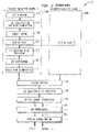
- FIG. 2illustrated is a diagram, generally designated 200 , showing the coding, multiplexing and processing performed by the transmit unit 140 for downlink data transmission in accordance with the WCDMA standard.
- Downlinkrefers to transmission from a base station to a user terminal.
- Uplinkrefers to transmission from the user equipment to the base station.
- the coding, multiplexing and processing blocks shown in FIG. 2are generally performed by the transmit channel data processor 104 shown in FIG. 1 .
- UMTScurrently supports 16 transport formats for WCDMA.
- TTItransmission time intervals
- the TTIis transport channel specific, and can be one of the following intervals: 10 ms, 20 ms, 40 ms or 80 ms.
- Other portions of the WCDMA systemsupport concurrent transmission of multiple transport channels.
- Each transport channel block 240performs substantially the same processing steps.
- the entire transport blockis used to calculate CRC parity bits and attach them (a step 202 ) to the end of the transport block.
- the CRC parity bitsare used for error detection.
- Transport blocks with the CRC attachmentsare serially concatenated. If the number of bits in a TTI is larger than the maximum size of the code block, the code block is segmented into a number of equal-sized code blocks (a step 204 ).
- the maximum size of the code blockdepends upon the type of coding used for the particular transport channel. Coding schemes supported by the WCDMA standard are convolutional coding, turbo coding and no coding.
- each of the code blocksis coded using one of the supported coding schemes. In the illustrated embodiment, a convolutional code is used.
- Rate matchingis performed in a step 208 .
- Rate matchingmeans that bits on a transport channel are repeated or removed (punctured).
- bitsare repeated or punctured in order to match the number of bits to be transmit to the number of bits available.
- unused bit positionsare filled by insertion of discontinuous transmission (DTX) indication bits in a step 210 .
- the DTX indication bitsare not actually transmitted; the DTX indication bits identify when transmission should be turned off.
- the bitsare interleaved in order to reduce the noise sensitivity of the data.
- the particular way in which the bits are interleavedis pre-determined and defined in the WCDMA standard.
- the interleaving time intervalis also known as the transmission time interval (TTI).
- the bits to transportare segmented and mapped onto consecutive transport channel radio frames in a step 214 .
- Each transport channel radio framecorresponds to a 10 ms radio frame period.
- the transport channel trafficmay be interleaved over 1, 2, 4 or 8 radio frame periods.
- a step 216calls for the radio frames from all transport channels to be serially multiplexed into a coded composite transport channel CCTrCH. More DTX indication bits may be inserted (in a step 218 ) to make the number of bits to be transmitted match the number of bits available. If multiple physical channels are to be used, the bits are segmented into separate physical channels in a step 220 .
- a physical channelcan carry transport channels that have different TTIs.
- a second interleaving of bits in each radio frame for each physical channeloccurs in a step 222 .
- the interleavingallows for greater time diversity and reduced noise sensitivity.
- a step 224calls for the interleaved radio frames to be mapped to their respective physical channels for transmission.
- FIG. 3illustrated is a diagram, generally designated 300 , showing the processing, de-multiplexing and decoding performed by the receiver unit 160 for downlink data transmission in accordance with the WCDMA standard.
- the processing in the block diagram 300performed by the receive channel data processor 118 shown in FIG. 1 , is a complementary set of receiver functions that reverse the specific operations performed by the transmit channel data processor 104 and described in detail in FIG. 2 .
- the modulated signalis received, processed and digitized by the receiver baseband processor 116 shown in FIG. 1 .
- the receiver baseband processor 116passes the symbols for each physical channel used for data transmission to the receive channel data processor 118 .
- Each symbolcorresponds to a transmitted bit or group of bits.
- the symbols from each physical channelare de-interleaved.
- the symbolsare then serially concatenated in a step 304 .
- all DTX indicator bitsare detected and removed in a step 306 .
- the symbolsare de-multiplexed into different transport channels.
- the radio frames for each transport channelare provided to their respective transport channel processing sections 340 .
- each transport channel processing section 340the radio frames are serially concatenated in a step 310 .
- Each channelmay contain one or more transport channel radio frames and corresponds to the TTI used at the transmitter.
- the symbolsare de-interleaved and DTX indication bits are identified and removed in a step 314 .
- a step 316inverse rate matching to accumulate repeated symbols and insertion of “don't cares” for deleted symbols is performed.
- the channel decoderdecodes each coded block in the transport channel.
- the decoded blocksare concatenated and segmented in a step 320 into their respective transport blocks.
- the CRC parity checkis performed in a step 322 on each transport block.
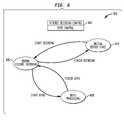
- FIG. 4illustrated is a block diagram of a channel decoder, generally designated 400 , constructed in accordance with the principles of the present invention.
- the channel decoder 400is an embodiment of the channel decoder function described in step 318 of FIG. 3 .
- Channel decoder 400is part of the receiver path of a WCDMA compliant transmitter and receiver and incorporates a system or method constructed or carried out according to the principles of the invention.
- the channel decoder 400includes a Viterbi decoder VD, a traceback circuit TC, a BTFD point selection circuit BTFD_PSC and a transport decode circuit TDC.
- the Viterbi decoder VDdecodes the sequence of WCDMA symbols into a frame.
- BTFDis used to determine the transport format used.
- BTFD schemesare search processes that look for valid CRC bits in the frames to identify the overlying transport format.
- the following constraintsare applied: (1) only one coded composite transport channel (CCTrCH) is received; (2) the number of CCTrCH bits per radio frame is 600 or less; (3) the number of transport format combinations of the CCTrCH is 64 or less; (4) fixed positions of the transport channels are used on the CCTrCH to be detectable; (5) convolutional coding is used on all explicitly detected TrCHs; (6) CRC with non-zero length is appended to transport blocks on all explicitly detected TrCHs; (7) at least one transport block shall be transmitted per TTI on each explicitly detectable TrCH; (8) the number of explicitly detectable TrCHs is 3 or less; (9) for all explicitly detectable TrCHs i, the number of code blocks in one TTI (C 1 ) shall not exceed 1; (10) the sum of the transport format set sizes of all explicitly detected TrCHs is 16 or less; and (11) at least one TrCH can be used as the
- the traceback circuit TCassociated with Viterbi decoder VD, performs a zero state BTFD traceback function with respect to at least a Viterbi-decoded portion of the frame.
- the traceback functionis dependent upon a relative position of a BTFD checkpoint.
- the traceback functiongenerates hard decision bits.
- the BTFD point selection circuit BTFD_PSCassociated with the Viterbi decoder VD, employs hard decision bits to determine a location of a BTFD point with respect to the frame.
- the transport decode circuit TDCcoupled to the BTFD point selection circuit BTFD_PSC, employs the BTFD point to extract user bits from the frame.
- the Viterbi decoding engineincludes a data fetch (DF), a forward trellis processor (FTP), a path metric memory (PMM), a butterfly structure with normalization (BSN), a normalization factor calculator (NFC), a Viterbi traceback processor (VTP) and a data packer (DP).
- DFdata fetch
- FTPforward trellis processor
- PMMpath metric memory
- BSNbutterfly structure with normalization
- NFCnormalization factor calculator
- VTPViterbi traceback processor
- DPdata packer
- the DFpasses the received frames of data to the BSN for normal Viterbi decoding.
- the calculated path metric values for Viterbi decodingare stored in the PMM.
- the Path Metric Memory PMMcontains eight banks of memory, each bank storing a number of path metric values depending on the code constraint.
- the path metric valuesare read out, normalized and presented to the BSN.
- the BSNcalculates new path metric values and passes them to the FTP.
- the BSNalso calculates decision bits, which are aggregated into bytes and written to the TC.
- the winning state, corresponding to the maximum path metric, for each trellis rowis delivered to the VTP.
- the winning state for each trellis rowbecomes the starting point for the traceback process.
- the VTPincludes a Traceback Circuit (TC), a BTFD Point Selection Circuit (BTFD_PSC) and a Transport Decode Circuit (TDC).
- the TCperforms the traceback function while the at least Viterbi decoded portion of the frame is stored in a buffer.
- the TCreceives input from the BSN of the winning state for each trellis row as well as a clock signal input.
- the TCexamines each trellis row to determine the largest value to be used as a starting point from zero state, no matter what the last winning state is.
- the TC and the BTFD_PSCare integral to the Viterbi decoder.
- the TC and the BTFD_PSCmay be associated with circuitry adjacent to the Viterbi decoder.
- s ⁇ ( n end )10 ⁇ ⁇ log 10 ⁇ a 0 ⁇ ( n end ) - a min ⁇ ( n end ) a max ⁇ ( n end ) - a min ⁇ ( n end ) ⁇ ⁇ and ⁇ ⁇ the ⁇ ⁇ CRC , where a max (n end ), a min (n end ), and a 0 (n end ) are three path metrics (max, min and zero-state) at a checkpoint n end .
- a correct BTFD pointmay be declared only if S(n end ) ⁇ D and the CRC test passes. The final conclusion on the transport format is the point with minimum S(n end ) ⁇ D and a pass of the CRC test.
- the BTFD_PSCperforms the CRC test, threshold calculations and comparisons and sets hard decision bits for BTFD. Then the BTFD_PSC determines the location of the BTFD point with respect to the frame while the hard decision bits are stored in a buffer.
- the BTFDmay be an integral part of the Viterbi decoder.
- the Viterbi decodercan be implemented with a truncated version, that is, using a fixed window size traceback instead of full frame length traceback. In this embodiment, the whole frame is partitioned into small blocks of the traceback window size. A normal block is decoded based on two blocks (the current and the next) of path metric computation and the traceback. The traceback is done from a maximum path metric state except for the last two blocks. The last two blocks are decoded by tracing back from zero state at once (decoder flushing).
- the BTFD checkpointis positioned (1) at a traceback point, (2) within a traceback window or (3) at an end of the frame.
- the followingpresents a one-pass zero state traceback solution that corresponds to the three positions set forth above.
- TrLDecL
- n endk*TrL
- n endk*TrL+M
- n endL for some integer k and M>0.
- An extra buffer BTFD_temp of size 2*TrL bitsis included to store the hard decision bits that come out of the zero state traceback.
- a temporary buffer DEC_temp of TrL bitsis also included to store some decoder output.
- n endL+NumTailBits
- the third step of the one-pass BTFD algorithmcan be implemented in hardware as an integral part of the Viterbi decoder with BTFD.
- DSPmay be used to perform the data I/O operations.
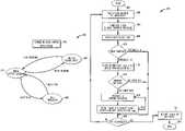
- FIG. 6illustrated is an embodiment of a BTFD control state machine, generally designated 600 , constructed in accordance with the principles of the invention.
- BTFDis performed in parallel with Viterbi decoding, thereby significantly decreasing the time and effort required to perform BTFD. This not only allows BTFD to be performed with respect to high rate channels, but also allows BTFD to be performed on channels of any rate more power-efficiently.
- the Viterbi decoding control and BTFD control 602directs the BTFD control state machine to move from the initial decode state 604 and to start decoding the incoming frames, thus initiating normal Viterbi decoding in state 606 .
- the Viterbi decoderruns to the first checkpoint, then starts BTFD, moving to state 608 : BTFD processing.
- state 606is resumed and the next checkpoint decoded.
- state 608is resumed for BTFD processing.
- the Viterbi decoding and BTFD processingcontinue until the final checkpoint is reached and decoding is finished. Then, the state returns to the initial decode state 604 .
- FIG. 7illustrated is a functional block diagram for BTFD threshold computation and comparison, generally designated 700 , constructed in accordance with the principles of the present invention.
- the main function of 700is to calculate the threshold and compare to previous thresholds.
- a PMM retrieve and compare block 702receives the two inputs ⁇ (max) and ⁇ (min), performs an addition and passes the output ⁇ (max) ⁇ (min) to multiplier 708 .
- the multiplier 708multiplies this input by D*, producing the output: D* ⁇ (max) ⁇ (min) ⁇ . This output is an input to adder 710 .
- the adder 706receives inputs ⁇ (0) and ⁇ (min), performs an addition and passes the output ⁇ (0) ⁇ (min) to an inverter and then to the adder 710 .
- the adder 710adds its two inputs to produce the following output: D* ⁇ (max) ⁇ (min) ⁇ (0) ⁇ (min) ⁇ . This output is the threshold to test.
- the comparator 714tests whether the threshold is greater than zero, and also compares the current threshold to the previous threshold 712 . Depending on the result of the comparison, the points are either updated or bypassed. If the current threshold is greater than the previous threshold, then update the n win point and previous threshold with the current point and threshold.
- FIG. 8illustrated is a flow diagram of an embodiment of a method of performing the one-pass BTFD, generally designated 800 , constructed in accordance with the principles of the present invention.
- the method 800starts in step 802 with an intent to decode the received frames using one-pass BTFD.
- the Viterbi decoderis run to the first checkpoint. Whole frames of data are transferred into the decoder input buffer.
- the VTPis configured with constraint length, code rate, CRC format and the first checkpoint.
- the VTPis run to the first BTFD checkpoint.
- hard decision bitsare temporarily stored in the DEC_temp register.
- a first decisional step 810the current threshold is checked. If a sufficient threshold is ascertained in the first decisional step 810 , the method 800 proceeds to step 812 . In an exemplary embodiment, a sufficient threshold is non-negative. In the step 812 , the decoder is flushed from the zero state, and hard decision bits are decoded.
- step 814the CRC test is performed. If the CRC test passes, the method 800 proceeds to step 816 .
- step 816the current threshold, Threshold(n end ), is calculated and compared to the previous stored threshold, Threshold(n win ).
- step 818if the current threshold, Threshold(n end ), is greater than or equal to previous threshold, Threshold(n win ), then endpoints and thresholds are updated. That is, n end and Threshold(n end ) are stored in n win and Threshold(n win ) respectively.
- the hard decision bitsare also buffered in BFTD_temp. The method 800 then proceeds to a third decisional step 820 .
- the method 800proceeds to the third decisional step 820 .
- the method 800determines whether the last BTFD checkpoint has been processed. If it is not the last BTFD checkpoint, the method 800 returns to step 804 . If the last BTFD checkpoint has been processed, the method 800 proceeds to step 822 . In step 822 , n win or a bad frame is declared. The method 800 ends in step 824 .
Landscapes
- Engineering & Computer Science (AREA)
- Computer Networks & Wireless Communication (AREA)
- Signal Processing (AREA)
- Artificial Intelligence (AREA)
- Error Detection And Correction (AREA)
Abstract
Description
where amax(nend), amin(nend), and a0(nend) are three path metrics (max, min and zero-state) at a checkpoint nend. A correct BTFD point may be declared only if S(nend)≦D and the CRC test passes. The final conclusion on the transport format is the point with minimum S(nend)≦D and a pass of the CRC test.
then check only whether the threshold is positive. The valid points are those with Threshold(nend)≧0, and the final winner is the point with the largest Threshold(nend) ; that is, nwin=arg maxn
Note that
should be programmed after system calibration based upon performance evaluation.
| TABLE 1 |
| Sub-algorithm I |
| (1) Trace back from the state with maximum path metric at | ||
| timing moment nendto decode the portion with time index [(k − | ||
| 2)*TrL, (k − 1)*TrL]. This is normal Viterbi decoder operation. | ||
| Buffer the hard decision bits into DEC_temp. | ||
| (2) Check threshold: Is Threshold(nend) >= 0? | ||
| (3) If threshold check passes, flush decoder from zero state | ||
| and decode hard decision bits with time index [(k − 2)*TrL, | ||
| k*TrL]. Note that portion [(k − 2)*TrL, (k − 1)*TrL] gets re- | ||
| decoded. If threshold check does not pass, go to step (5). | ||
| (4) Calculate and check CRC. If CRC passes, compare | ||
| Threshold(nend) with Threshold(nwin). If Threshold(nend) >= | ||
| Threshold(nwin), then update nwin= nend, Threshold (nwin) = | ||
| Threshold(nend) and buffer the hard decision bits into | ||
| BTFD_temp. | ||
| (5) Copy the hard decision bits from DEC_temp into decoder | ||
| output buffer to replace the corresponding portion with time | ||
| index [(k − 2)*TrL, (k − 1)*TrL]. Continue the Viterbi decoder | ||
| operation to decode the portion with time index [(k − 1)*TrL, | ||
| k*TrL] again (traceback from state with maximum path metric at | ||
| time moment (k + 1)*TrL later). | ||
| TABLE 2 |
| Sub-algorithm II |
| (1) Trace back from the state with maximum path metric at | ||
| timing moment (k + 1)*TrL to decode the portion with time index | ||
| [(k − 1)*TrL, k*TrL]. Buffer the hard decision bits into | ||
| DEC_temp. | ||
| (2) Check threshold: Is Threshold(nend) >= 0? | ||
| (3) If threshold check passes, flush decoder from zero state | ||
| and decode hard decision bits with time index [(k − 1)*TrL, nend]. | ||
| Note that portion [(k − 1)*TrL, k*TrL] gets re-decoded. If | ||
| threshold check does not pass, go to step (5). | ||
| (4) Calculate and check CRC. If CRC passes, compare | ||
| Threshold(nend) with Threshold(nwin). If Threshold(nend) >= | ||
| Threshold(nwin), then update nwin= nend, Threshold(nwin) = | ||
| Threshold(nend) and buffer the hard decision bits into | ||
| BTFD_temp. | ||
| (5) Copy the hard decision bits from DEC_temp into decoder | ||
| output buffer to replace the corresponding portion with time | ||
| index [(k − 1)*TrL, k*TrL]. Continue the Viterbi decoder | ||
| operation to decode the portion with time index [k*TrL, | ||
| (k + 1)*TrL] again (traceback from state with maximum path metric | ||
| at time moment (k + 2)*TrL later). | ||
| TABLE 3 |
| Sub-algorithm III |
| (1) Flush decoder from zero state and decode hard decision bits | ||
| with time index [(k − 1)*TrL, nend]. Note that no temporary | ||
| buffer is needed in this case. | ||
| (2) Check threshold: Is Threshold(nend) >= 0? | ||
| (3) If threshold check passes, calculate and check CRC. If CRC | ||
| passes, compare Threshold(nend) with Threshold(nwin). If | ||
| Threshold(nend) >= Threshold(nwin), then update nwin= nendand | ||
| Threshold(nwin) = Threshold(nend). If CRC does not pass, do | ||
| nothing. Decoding and BTFD finished. | ||
| TABLE 4 |
| One-pass BTFD algorithm |
| Step(1): Initialize nwin= NULL and Threshold (nwin) = 0. | |
| Step(2): For each BTFD checkpoint nend{ |
| If nend= k*TrL and nend< L+NumTailBits { |
| Execute Sub-algorithm I; |
| } else if nend= k*TrL and nend<L+NumTailBits { |
| Execute Sub-algorithm II; |
| } else if nend= L+NumTailBits { |
| Execute Sub-algorithm III; |
| } |
| } |
| Step (3): If(nwin!= NULL) { |
| Declare nwin; | |
| If(nwin< L+NumTailBits) { |
| Read out hard bits stored in BTFD_temp for Sub- |
| algorithm I and II; |
| Overwrite the corresponding portion of the |
| Decoder output buffer; |
| } |
| } else { |
| Declare a bad frame; |
| } | ||
Threshold(nend)=D*{amax(nend)−amin(nend)}−{a0(nend)−amin(nend)}≧0
Claims (21)
Priority Applications (1)
| Application Number | Priority Date | Filing Date | Title |
|---|---|---|---|
| US10/292,268US7463702B2 (en) | 2002-11-12 | 2002-11-12 | System and method for one-pass blind transport format detection |
Applications Claiming Priority (1)
| Application Number | Priority Date | Filing Date | Title |
|---|---|---|---|
| US10/292,268US7463702B2 (en) | 2002-11-12 | 2002-11-12 | System and method for one-pass blind transport format detection |
Publications (2)
| Publication Number | Publication Date |
|---|---|
| US20040091067A1 US20040091067A1 (en) | 2004-05-13 |
| US7463702B2true US7463702B2 (en) | 2008-12-09 |
Family
ID=32229417
Family Applications (1)
| Application Number | Title | Priority Date | Filing Date |
|---|---|---|---|
| US10/292,268Expired - Fee RelatedUS7463702B2 (en) | 2002-11-12 | 2002-11-12 | System and method for one-pass blind transport format detection |
Country Status (1)
| Country | Link |
|---|---|
| US (1) | US7463702B2 (en) |
Cited By (13)
| Publication number | Priority date | Publication date | Assignee | Title |
|---|---|---|---|---|
| US20070233890A1 (en)* | 2004-06-03 | 2007-10-04 | Valadon Cyril G F | Data Stream Recovery |
| US20070234190A1 (en)* | 2004-05-27 | 2007-10-04 | Matsushita Electric Industrial Co., Ltd. | Viterbi Decoding Apparatus and Viterbi Decoding Method |
| US8023950B2 (en) | 2003-02-18 | 2011-09-20 | Qualcomm Incorporated | Systems and methods for using selectable frame durations in a wireless communication system |
| US8081598B2 (en) | 2003-02-18 | 2011-12-20 | Qualcomm Incorporated | Outer-loop power control for wireless communication systems |
| US8150407B2 (en) | 2003-02-18 | 2012-04-03 | Qualcomm Incorporated | System and method for scheduling transmissions in a wireless communication system |
| US8201039B2 (en) | 2003-08-05 | 2012-06-12 | Qualcomm Incorporated | Combining grant, acknowledgement, and rate control commands |
| US8391249B2 (en) | 2003-02-18 | 2013-03-05 | Qualcomm Incorporated | Code division multiplexing commands on a code division multiplexed channel |
| US8477592B2 (en) | 2003-05-14 | 2013-07-02 | Qualcomm Incorporated | Interference and noise estimation in an OFDM system |
| US8526966B2 (en) | 2003-02-18 | 2013-09-03 | Qualcomm Incorporated | Scheduled and autonomous transmission and acknowledgement |
| US8548387B2 (en) | 2003-03-06 | 2013-10-01 | Qualcomm Incorporated | Method and apparatus for providing uplink signal-to-noise ratio (SNR) estimation in a wireless communication system |
| US8576894B2 (en) | 2003-03-06 | 2013-11-05 | Qualcomm Incorporated | Systems and methods for using code space in spread-spectrum communications |
| US8699452B2 (en) | 2003-02-18 | 2014-04-15 | Qualcomm Incorporated | Congestion control in a wireless data network |
| US9998379B2 (en) | 2003-02-18 | 2018-06-12 | Qualcomm Incorporated | Method and apparatus for controlling data rate of a reverse link in a communication system |
Families Citing this family (13)
| Publication number | Priority date | Publication date | Assignee | Title |
|---|---|---|---|---|
| JP3440092B1 (en)* | 2002-03-29 | 2003-08-25 | 松下電器産業株式会社 | Error correction decoding device and error correction decoding method |
| US7286846B2 (en)* | 2003-02-18 | 2007-10-23 | Qualcomm, Incorporated | Systems and methods for performing outer loop power control in wireless communication systems |
| US7260659B2 (en)* | 2003-06-30 | 2007-08-21 | Intel Corporation | Rate matching apparatus, systems, and methods |
| US7277496B2 (en)* | 2003-06-30 | 2007-10-02 | Intel Corporation | Device, system and method for blind format detection |
| US7643993B2 (en)* | 2006-01-05 | 2010-01-05 | Broadcom Corporation | Method and system for decoding WCDMA AMR speech data using redundancy |
| JP4408783B2 (en) | 2004-09-29 | 2010-02-03 | Necエレクトロニクス株式会社 | Decoding device and decoding method |
| EP1648106A1 (en)* | 2004-10-15 | 2006-04-19 | Melco Mobile Communications Europe | Method and device for multiplexing a transport channel in flexible position |
| JP2008523755A (en)* | 2004-12-13 | 2008-07-03 | フリースケール セミコンダクター インコーポレイテッド | Apparatus and method for detecting end point of information frame |
| US8086257B2 (en)* | 2005-08-11 | 2011-12-27 | Alcatel Lucent | Dedicated control channel detection for enhanced dedicated channel |
| US8121104B2 (en) | 2006-05-31 | 2012-02-21 | Agere Systems Inc. | Method and apparatus for blind transport format detection using discontinuous transmission (DTX) detection |
| US7734308B2 (en)* | 2006-12-27 | 2010-06-08 | Alcatel-Lucent Usa Inc. | Power reduction methods in enhanced transmitters and receivers |
| CN102301782B (en)* | 2009-02-23 | 2014-07-30 | 飞思卡尔半导体公司 | process data flow |
| US8843792B2 (en)* | 2012-02-03 | 2014-09-23 | Blackberry Limited | Method and apparatus for reducing false detection of control information |
Citations (8)
| Publication number | Priority date | Publication date | Assignee | Title |
|---|---|---|---|---|
| US5928378A (en)* | 1996-08-23 | 1999-07-27 | Daewoo Electronics Co., Ltd. | Add-compare-select processor in Viterbi decoder |
| US20030007580A1 (en)* | 2001-06-08 | 2003-01-09 | Toshio Nagata | Blind transport format detection system and method |
| US20030108011A1 (en)* | 2001-12-06 | 2003-06-12 | Yong-Su Lee | Blind rate detection method and device in asynchronous mobile communication system |
| US6765887B1 (en)* | 2000-09-06 | 2004-07-20 | Qualcomm Inc. | Method and apparatus for processing a received transmission based on processing delays requirement |
| US6885701B2 (en)* | 2000-08-31 | 2005-04-26 | Sony Corporation | Data demodulation apparatus and method |
| US7024602B2 (en)* | 2000-06-21 | 2006-04-04 | Fujitsu Limited | Transmission format detection method |
| US7072926B2 (en)* | 2001-06-08 | 2006-07-04 | Texas Instruments Incorporated | Blind transport format detection system and method with logarithm approximation for reliability figure |
| US7228491B2 (en)* | 2002-12-18 | 2007-06-05 | Sony Ericsson Mobile Communications Japan, Inc. | Signal processing device and signal processing method |
- 2002
- 2002-11-12USUS10/292,268patent/US7463702B2/ennot_activeExpired - Fee Related
Patent Citations (9)
| Publication number | Priority date | Publication date | Assignee | Title |
|---|---|---|---|---|
| US5928378A (en)* | 1996-08-23 | 1999-07-27 | Daewoo Electronics Co., Ltd. | Add-compare-select processor in Viterbi decoder |
| US7024602B2 (en)* | 2000-06-21 | 2006-04-04 | Fujitsu Limited | Transmission format detection method |
| US6885701B2 (en)* | 2000-08-31 | 2005-04-26 | Sony Corporation | Data demodulation apparatus and method |
| US6765887B1 (en)* | 2000-09-06 | 2004-07-20 | Qualcomm Inc. | Method and apparatus for processing a received transmission based on processing delays requirement |
| US20030007580A1 (en)* | 2001-06-08 | 2003-01-09 | Toshio Nagata | Blind transport format detection system and method |
| US7072926B2 (en)* | 2001-06-08 | 2006-07-04 | Texas Instruments Incorporated | Blind transport format detection system and method with logarithm approximation for reliability figure |
| US20030108011A1 (en)* | 2001-12-06 | 2003-06-12 | Yong-Su Lee | Blind rate detection method and device in asynchronous mobile communication system |
| US7184409B2 (en)* | 2001-12-06 | 2007-02-27 | Electronics And Telecommunications Research Institute | Blind rate detection method and device in asynchronous mobile communication system |
| US7228491B2 (en)* | 2002-12-18 | 2007-06-05 | Sony Ericsson Mobile Communications Japan, Inc. | Signal processing device and signal processing method |
Non-Patent Citations (1)
| Title |
|---|
| Insoo Sohn, Seoyoung Lee "Blind Rate Detection Algorithm in WCDMA Mobile Receiver", IEEE 2001.* |
Cited By (19)
| Publication number | Priority date | Publication date | Assignee | Title |
|---|---|---|---|---|
| US8391249B2 (en) | 2003-02-18 | 2013-03-05 | Qualcomm Incorporated | Code division multiplexing commands on a code division multiplexed channel |
| US8526966B2 (en) | 2003-02-18 | 2013-09-03 | Qualcomm Incorporated | Scheduled and autonomous transmission and acknowledgement |
| US9998379B2 (en) | 2003-02-18 | 2018-06-12 | Qualcomm Incorporated | Method and apparatus for controlling data rate of a reverse link in a communication system |
| US8977283B2 (en) | 2003-02-18 | 2015-03-10 | Qualcomm Incorporated | Scheduled and autonomous transmission and acknowledgement |
| US8023950B2 (en) | 2003-02-18 | 2011-09-20 | Qualcomm Incorporated | Systems and methods for using selectable frame durations in a wireless communication system |
| US8081598B2 (en) | 2003-02-18 | 2011-12-20 | Qualcomm Incorporated | Outer-loop power control for wireless communication systems |
| US8150407B2 (en) | 2003-02-18 | 2012-04-03 | Qualcomm Incorporated | System and method for scheduling transmissions in a wireless communication system |
| US8699452B2 (en) | 2003-02-18 | 2014-04-15 | Qualcomm Incorporated | Congestion control in a wireless data network |
| US8576894B2 (en) | 2003-03-06 | 2013-11-05 | Qualcomm Incorporated | Systems and methods for using code space in spread-spectrum communications |
| US8548387B2 (en) | 2003-03-06 | 2013-10-01 | Qualcomm Incorporated | Method and apparatus for providing uplink signal-to-noise ratio (SNR) estimation in a wireless communication system |
| US8676128B2 (en) | 2003-03-06 | 2014-03-18 | Qualcomm Incorporated | Method and apparatus for providing uplink signal-to-noise ratio (SNR) estimation in a wireless communication system |
| US8705588B2 (en) | 2003-03-06 | 2014-04-22 | Qualcomm Incorporated | Systems and methods for using code space in spread-spectrum communications |
| US8477592B2 (en) | 2003-05-14 | 2013-07-02 | Qualcomm Incorporated | Interference and noise estimation in an OFDM system |
| US8489949B2 (en) | 2003-08-05 | 2013-07-16 | Qualcomm Incorporated | Combining grant, acknowledgement, and rate control commands |
| US8201039B2 (en) | 2003-08-05 | 2012-06-12 | Qualcomm Incorporated | Combining grant, acknowledgement, and rate control commands |
| US20070234190A1 (en)* | 2004-05-27 | 2007-10-04 | Matsushita Electric Industrial Co., Ltd. | Viterbi Decoding Apparatus and Viterbi Decoding Method |
| US7861146B2 (en)* | 2004-05-27 | 2010-12-28 | Panasonic Corporation | Viterbi decoding apparatus and Viterbi decoding method |
| US7916754B2 (en)* | 2004-06-03 | 2011-03-29 | Mstar Semiconductor, Inc. | Data stream recovery |
| US20070233890A1 (en)* | 2004-06-03 | 2007-10-04 | Valadon Cyril G F | Data Stream Recovery |
Also Published As
| Publication number | Publication date |
|---|---|
| US20040091067A1 (en) | 2004-05-13 |
Similar Documents
| Publication | Publication Date | Title |
|---|---|---|
| US7463702B2 (en) | System and method for one-pass blind transport format detection | |
| AU2003214677B2 (en) | Apparatus and Method for Receiving Packet Data Control Channel in a Mobile Communication System | |
| US7688915B2 (en) | Method and system for blindly detecting a discontinuously transmitted shared channel, in particular blind high speed shared control channels detection | |
| KR101504375B1 (en) | Reliable decoding of a high-speed shared control channel | |
| US5570369A (en) | Reduction of power consumption in a mobile station | |
| US6108372A (en) | Method and apparatus for decoding variable rate data using hypothesis testing to determine data rate | |
| US6813323B2 (en) | Decoding method and communication terminal apparatus | |
| US6567938B2 (en) | Convolution decoding terminated by an error detection block code with distributed parity bits | |
| US8223869B2 (en) | Control channel detection scheme | |
| US20050025076A1 (en) | Scaling and quantizing soft-decision metrics for decoding | |
| CN100375472C (en) | Apparatus and method for determining transmission rate of variable rate data | |
| JPH08195683A (en) | Data receiving device | |
| WO1999014885A2 (en) | Time diversity in a tdma system | |
| US20100323637A1 (en) | Method and apparatus for conveying antenna configuration information via masking | |
| EP1135909A1 (en) | Systems and methods for receiving a modulated signal containing encoded and unencoded bits using multi-pass demodulation | |
| KR100344605B1 (en) | Bad frame detector and turbo decoder | |
| US8259867B2 (en) | Methods and systems for turbo decoding in a wireless communication system | |
| US20020108090A1 (en) | Blind transport format detection of turbo-coded data | |
| JPH11234143A (en) | Syndrome-based channel quality or message structure determining device | |
| US20020080725A1 (en) | Blind rate determination | |
| US20200322070A1 (en) | Method and apparatus for low power synchronization of bluetooth systems | |
| US20020107987A1 (en) | Compression based on channel characteristics | |
| JPH10126387A (en) | Bit error rate measurement device using Viterbi decoder | |
| US8230313B2 (en) | Low-power predecoding based viterbi decoding | |
| US8121104B2 (en) | Method and apparatus for blind transport format detection using discontinuous transmission (DTX) detection |
Legal Events
| Date | Code | Title | Description |
|---|---|---|---|
| AS | Assignment | Owner name:AGERE SYSTEMS INC., PENNSYLVANIA Free format text:ASSIGNMENT OF ASSIGNORS INTEREST;ASSIGNORS:AMMER, GERHARD;SMITH, III, WILLIAM H.;XU, SHUZHAN;REEL/FRAME:013489/0958;SIGNING DATES FROM 20021021 TO 20021024 | |
| STCF | Information on status: patent grant | Free format text:PATENTED CASE | |
| FEPP | Fee payment procedure | Free format text:PAYOR NUMBER ASSIGNED (ORIGINAL EVENT CODE: ASPN); ENTITY STATUS OF PATENT OWNER: LARGE ENTITY | |
| FPAY | Fee payment | Year of fee payment:4 | |
| AS | Assignment | Owner name:DEUTSCHE BANK AG NEW YORK BRANCH, AS COLLATERAL AG Free format text:PATENT SECURITY AGREEMENT;ASSIGNORS:LSI CORPORATION;AGERE SYSTEMS LLC;REEL/FRAME:032856/0031 Effective date:20140506 | |
| AS | Assignment | Owner name:AVAGO TECHNOLOGIES GENERAL IP (SINGAPORE) PTE. LTD Free format text:ASSIGNMENT OF ASSIGNORS INTEREST;ASSIGNOR:AGERE SYSTEMS LLC;REEL/FRAME:035365/0634 Effective date:20140804 | |
| AS | Assignment | Owner name:AGERE SYSTEMS LLC, PENNSYLVANIA Free format text:TERMINATION AND RELEASE OF SECURITY INTEREST IN PATENT RIGHTS (RELEASES RF 032856-0031);ASSIGNOR:DEUTSCHE BANK AG NEW YORK BRANCH, AS COLLATERAL AGENT;REEL/FRAME:037684/0039 Effective date:20160201 Owner name:LSI CORPORATION, CALIFORNIA Free format text:TERMINATION AND RELEASE OF SECURITY INTEREST IN PATENT RIGHTS (RELEASES RF 032856-0031);ASSIGNOR:DEUTSCHE BANK AG NEW YORK BRANCH, AS COLLATERAL AGENT;REEL/FRAME:037684/0039 Effective date:20160201 | |
| AS | Assignment | Owner name:BANK OF AMERICA, N.A., AS COLLATERAL AGENT, NORTH CAROLINA Free format text:PATENT SECURITY AGREEMENT;ASSIGNOR:AVAGO TECHNOLOGIES GENERAL IP (SINGAPORE) PTE. LTD.;REEL/FRAME:037808/0001 Effective date:20160201 Owner name:BANK OF AMERICA, N.A., AS COLLATERAL AGENT, NORTH Free format text:PATENT SECURITY AGREEMENT;ASSIGNOR:AVAGO TECHNOLOGIES GENERAL IP (SINGAPORE) PTE. LTD.;REEL/FRAME:037808/0001 Effective date:20160201 | |
| FPAY | Fee payment | Year of fee payment:8 | |
| AS | Assignment | Owner name:AVAGO TECHNOLOGIES GENERAL IP (SINGAPORE) PTE. LTD., SINGAPORE Free format text:TERMINATION AND RELEASE OF SECURITY INTEREST IN PATENTS;ASSIGNOR:BANK OF AMERICA, N.A., AS COLLATERAL AGENT;REEL/FRAME:041710/0001 Effective date:20170119 Owner name:AVAGO TECHNOLOGIES GENERAL IP (SINGAPORE) PTE. LTD Free format text:TERMINATION AND RELEASE OF SECURITY INTEREST IN PATENTS;ASSIGNOR:BANK OF AMERICA, N.A., AS COLLATERAL AGENT;REEL/FRAME:041710/0001 Effective date:20170119 | |
| AS | Assignment | Owner name:AVAGO TECHNOLOGIES INTERNATIONAL SALES PTE. LIMITE Free format text:MERGER;ASSIGNOR:AVAGO TECHNOLOGIES GENERAL IP (SINGAPORE) PTE. LTD.;REEL/FRAME:047195/0658 Effective date:20180509 | |
| AS | Assignment | Owner name:AVAGO TECHNOLOGIES INTERNATIONAL SALES PTE. LIMITE Free format text:CORRECTIVE ASSIGNMENT TO CORRECT THE EFFECTIVE DATE OF MERGER PREVIOUSLY RECORDED ON REEL 047195 FRAME 0658. ASSIGNOR(S) HEREBY CONFIRMS THE THE EFFECTIVE DATE IS 09/05/2018;ASSIGNOR:AVAGO TECHNOLOGIES GENERAL IP (SINGAPORE) PTE. LTD.;REEL/FRAME:047357/0302 Effective date:20180905 | |
| AS | Assignment | Owner name:AVAGO TECHNOLOGIES INTERNATIONAL SALES PTE. LIMITE Free format text:CORRECTIVE ASSIGNMENT TO CORRECT THE ERROR IN RECORDING THE MERGER PREVIOUSLY RECORDED AT REEL: 047357 FRAME: 0302. ASSIGNOR(S) HEREBY CONFIRMS THE ASSIGNMENT;ASSIGNOR:AVAGO TECHNOLOGIES GENERAL IP (SINGAPORE) PTE. LTD.;REEL/FRAME:048674/0834 Effective date:20180905 | |
| FEPP | Fee payment procedure | Free format text:MAINTENANCE FEE REMINDER MAILED (ORIGINAL EVENT CODE: REM.); ENTITY STATUS OF PATENT OWNER: LARGE ENTITY | |
| LAPS | Lapse for failure to pay maintenance fees | Free format text:PATENT EXPIRED FOR FAILURE TO PAY MAINTENANCE FEES (ORIGINAL EVENT CODE: EXP.); ENTITY STATUS OF PATENT OWNER: LARGE ENTITY | |
| STCH | Information on status: patent discontinuation | Free format text:PATENT EXPIRED DUE TO NONPAYMENT OF MAINTENANCE FEES UNDER 37 CFR 1.362 | |
| FP | Lapsed due to failure to pay maintenance fee | Effective date:20201209 |