US7462170B2 - Administration feeding set and valve mechanism - Google Patents
Administration feeding set and valve mechanismDownload PDFInfo
- Publication number
- US7462170B2 US7462170B2US10/853,958US85395804AUS7462170B2US 7462170 B2US7462170 B2US 7462170B2US 85395804 AUS85395804 AUS 85395804AUS 7462170 B2US7462170 B2US 7462170B2
- Authority
- US
- United States
- Prior art keywords
- administration feeding
- feeding set
- inlet
- control apparatus
- valve stem
- Prior art date
- Legal status (The legal status is an assumption and is not a legal conclusion. Google has not performed a legal analysis and makes no representation as to the accuracy of the status listed.)
- Expired - Lifetime, expires
Links
- 230000007246mechanismEffects0.000titleclaimsabstractdescription90
- 239000012530fluidSubstances0.000claimsabstractdescription97
- 230000037361pathwayEffects0.000claimsdescription10
- 238000000034methodMethods0.000abstractdescription4
- 238000011010flushing procedureMethods0.000description10
- 238000010586diagramMethods0.000description6
- 230000000903blocking effectEffects0.000description5
- 230000008569processEffects0.000description2
- 238000011144upstream manufacturingMethods0.000description2
- 230000005355Hall effectEffects0.000description1
- 238000001514detection methodMethods0.000description1
- 239000003814drugSubstances0.000description1
- 230000001939inductive effectEffects0.000description1
- 238000012986modificationMethods0.000description1
- 230000004048modificationEffects0.000description1
- 230000035764nutritionEffects0.000description1
- 235000016709nutritionNutrition0.000description1
- 230000002572peristaltic effectEffects0.000description1
Images


Classifications
- A—HUMAN NECESSITIES
- A61—MEDICAL OR VETERINARY SCIENCE; HYGIENE
- A61M—DEVICES FOR INTRODUCING MEDIA INTO, OR ONTO, THE BODY; DEVICES FOR TRANSDUCING BODY MEDIA OR FOR TAKING MEDIA FROM THE BODY; DEVICES FOR PRODUCING OR ENDING SLEEP OR STUPOR
- A61M5/00—Devices for bringing media into the body in a subcutaneous, intra-vascular or intramuscular way; Accessories therefor, e.g. filling or cleaning devices, arm-rests
- A61M5/14—Infusion devices, e.g. infusing by gravity; Blood infusion; Accessories therefor
- A61M5/168—Means for controlling media flow to the body or for metering media to the body, e.g. drip meters, counters ; Monitoring media flow to the body
- A—HUMAN NECESSITIES
- A61—MEDICAL OR VETERINARY SCIENCE; HYGIENE
- A61J—CONTAINERS SPECIALLY ADAPTED FOR MEDICAL OR PHARMACEUTICAL PURPOSES; DEVICES OR METHODS SPECIALLY ADAPTED FOR BRINGING PHARMACEUTICAL PRODUCTS INTO PARTICULAR PHYSICAL OR ADMINISTERING FORMS; DEVICES FOR ADMINISTERING FOOD OR MEDICINES ORALLY; BABY COMFORTERS; DEVICES FOR RECEIVING SPITTLE
- A61J15/00—Feeding-tubes for therapeutic purposes
- A61J15/0026—Parts, details or accessories for feeding-tubes
- A61J15/0076—Feeding pumps
- A—HUMAN NECESSITIES
- A61—MEDICAL OR VETERINARY SCIENCE; HYGIENE
- A61J—CONTAINERS SPECIALLY ADAPTED FOR MEDICAL OR PHARMACEUTICAL PURPOSES; DEVICES OR METHODS SPECIALLY ADAPTED FOR BRINGING PHARMACEUTICAL PRODUCTS INTO PARTICULAR PHYSICAL OR ADMINISTERING FORMS; DEVICES FOR ADMINISTERING FOOD OR MEDICINES ORALLY; BABY COMFORTERS; DEVICES FOR RECEIVING SPITTLE
- A61J15/00—Feeding-tubes for therapeutic purposes
- A61J15/0026—Parts, details or accessories for feeding-tubes
- A61J15/0092—Valves on feeding tubes
- A—HUMAN NECESSITIES
- A61—MEDICAL OR VETERINARY SCIENCE; HYGIENE
- A61M—DEVICES FOR INTRODUCING MEDIA INTO, OR ONTO, THE BODY; DEVICES FOR TRANSDUCING BODY MEDIA OR FOR TAKING MEDIA FROM THE BODY; DEVICES FOR PRODUCING OR ENDING SLEEP OR STUPOR
- A61M39/00—Tubes, tube connectors, tube couplings, valves, access sites or the like, specially adapted for medical use
- A61M39/22—Valves or arrangement of valves
- A61M39/223—Multiway valves
- A—HUMAN NECESSITIES
- A61—MEDICAL OR VETERINARY SCIENCE; HYGIENE
- A61M—DEVICES FOR INTRODUCING MEDIA INTO, OR ONTO, THE BODY; DEVICES FOR TRANSDUCING BODY MEDIA OR FOR TAKING MEDIA FROM THE BODY; DEVICES FOR PRODUCING OR ENDING SLEEP OR STUPOR
- A61M5/00—Devices for bringing media into the body in a subcutaneous, intra-vascular or intramuscular way; Accessories therefor, e.g. filling or cleaning devices, arm-rests
- A61M5/14—Infusion devices, e.g. infusing by gravity; Blood infusion; Accessories therefor
- A61M5/142—Pressure infusion, e.g. using pumps
- A61M5/14212—Pumping with an aspiration and an expulsion action
- A61M5/14232—Roller pumps
- A—HUMAN NECESSITIES
- A61—MEDICAL OR VETERINARY SCIENCE; HYGIENE
- A61M—DEVICES FOR INTRODUCING MEDIA INTO, OR ONTO, THE BODY; DEVICES FOR TRANSDUCING BODY MEDIA OR FOR TAKING MEDIA FROM THE BODY; DEVICES FOR PRODUCING OR ENDING SLEEP OR STUPOR
- A61M2205/00—General characteristics of the apparatus
- A61M2205/14—Detection of the presence or absence of a tube, a connector or a container in an apparatus
- A—HUMAN NECESSITIES
- A61—MEDICAL OR VETERINARY SCIENCE; HYGIENE
- A61M—DEVICES FOR INTRODUCING MEDIA INTO, OR ONTO, THE BODY; DEVICES FOR TRANSDUCING BODY MEDIA OR FOR TAKING MEDIA FROM THE BODY; DEVICES FOR PRODUCING OR ENDING SLEEP OR STUPOR
- A61M2205/00—General characteristics of the apparatus
- A61M2205/17—General characteristics of the apparatus with redundant control systems
- A—HUMAN NECESSITIES
- A61—MEDICAL OR VETERINARY SCIENCE; HYGIENE
- A61M—DEVICES FOR INTRODUCING MEDIA INTO, OR ONTO, THE BODY; DEVICES FOR TRANSDUCING BODY MEDIA OR FOR TAKING MEDIA FROM THE BODY; DEVICES FOR PRODUCING OR ENDING SLEEP OR STUPOR
- A61M2205/00—General characteristics of the apparatus
- A61M2205/60—General characteristics of the apparatus with identification means
- A61M2205/6018—General characteristics of the apparatus with identification means providing set-up signals for the apparatus configuration
- A—HUMAN NECESSITIES
- A61—MEDICAL OR VETERINARY SCIENCE; HYGIENE
- A61M—DEVICES FOR INTRODUCING MEDIA INTO, OR ONTO, THE BODY; DEVICES FOR TRANSDUCING BODY MEDIA OR FOR TAKING MEDIA FROM THE BODY; DEVICES FOR PRODUCING OR ENDING SLEEP OR STUPOR
- A61M2205/00—General characteristics of the apparatus
- A61M2205/60—General characteristics of the apparatus with identification means
- A61M2205/6045—General characteristics of the apparatus with identification means having complementary physical shapes for indexing or registration purposes
- A—HUMAN NECESSITIES
- A61—MEDICAL OR VETERINARY SCIENCE; HYGIENE
- A61M—DEVICES FOR INTRODUCING MEDIA INTO, OR ONTO, THE BODY; DEVICES FOR TRANSDUCING BODY MEDIA OR FOR TAKING MEDIA FROM THE BODY; DEVICES FOR PRODUCING OR ENDING SLEEP OR STUPOR
- A61M2205/00—General characteristics of the apparatus
- A61M2205/60—General characteristics of the apparatus with identification means
- A61M2205/6054—Magnetic identification systems
- A—HUMAN NECESSITIES
- A61—MEDICAL OR VETERINARY SCIENCE; HYGIENE
- A61M—DEVICES FOR INTRODUCING MEDIA INTO, OR ONTO, THE BODY; DEVICES FOR TRANSDUCING BODY MEDIA OR FOR TAKING MEDIA FROM THE BODY; DEVICES FOR PRODUCING OR ENDING SLEEP OR STUPOR
- A61M5/00—Devices for bringing media into the body in a subcutaneous, intra-vascular or intramuscular way; Accessories therefor, e.g. filling or cleaning devices, arm-rests
- A61M5/14—Infusion devices, e.g. infusing by gravity; Blood infusion; Accessories therefor
- A61M5/168—Means for controlling media flow to the body or for metering media to the body, e.g. drip meters, counters ; Monitoring media flow to the body
- A61M5/16877—Adjusting flow; Devices for setting a flow rate
- A61M5/16881—Regulating valves
Definitions
- the present inventionrelates to an administration feeding set adapted to be loaded to a flow control apparatus.
- the present inventionfurther relates to a valve mechanism adapted to be engaged to a flow control apparatus.
- Administering fluids containing medicine or nutrition to a patientis well known in the art.
- fluidis delivered to the patient by an administration feeding set loaded to a flow control apparatus, such as a peristaltic pump, which delivers fluid to the patient at a controlled rate of delivery.
- the administration feeding setwhen loaded to the flow control apparatus, comprises tubing that delivers fluid from a fluid source to a patient.
- a valve mechanismmay be located on the tubing for permitting or preventing fluid flow communication through the administration feeding set. Such a valve mechanism may be automatically operated to alternate positions that either prevent or permit fluid flow communication through the tubing when engaged to the flow control apparatus.
- each type of administration feeding sethas a physical appearance that may be indistinguishable from other kinds of administration feeding sets. Accordingly, it is important that the healthcare practitioner be able to readily identify the functional configuration of the administration feeding set being loaded to the flow control apparatus.
- an administration feeding sethaving a means for identifying the functional configuration of the feeding set and having a valve mechanism that can prevent disengagement of the administration feeding set loaded to the flow control apparatus.
- the present inventioncomprises an administration feeding comprising tubing adapted for fluid flow and further adapted to be loaded to the flow control apparatus.
- a valve mechanismis in direct communication with the tubing and adapted to engage the flow control apparatus.
- the administration feeding setcomprises a mounting member in direct communication with the tubing, wherein the mounting member is adapted to engage the tubing to the flow control apparatus and comprises a means for permitting identification of the functional configuration of the administration feeding set.
- the administration feeding setcomprises tubing adapted for fluid flow and further adapted to be loaded to the flow control apparatus. Further, the administration feeding set comprises a mounting member in direct communication with the tubing, wherein the mounting member is adapted to engage the tubing to the flow control apparatus and comprises a means for permitting identification of the functional configuration of the administration feeding set.
- the present inventionfurther relates to a valve mechanism that comprises a valve body having at least one inlet in communication with an outlet through a chamber and a valve stem rotatably disposed in the chamber.
- the valve stemhas a portion comprising a fluid pathway defining at least one fluid port. This valve mechanism is suitable for controlling fluid flow.
- the valve mechanismcomprises a valve body having at least one inlet in communication with an outlet through the chamber with the valve body further comprising a slot.
- a valve stemis rotatably disposed in the chamber with the valve stem having a portion comprising a channel. This valve mechanism is suitable for preventing disengagement of the valve mechanism from the flow control apparatus when the valve mechanism is in a position that permits fluid flow.
- the valve mechanismcomprises a valve body having at least one inlet in communication with an outlet through a chamber with the valve body further comprising a slot.
- a valve stemis rotatably disposed in the chamber.
- the valve stemhas a front portion comprising a fluid pathway defining at least one fluid port and a back portion comprising a channel. This valve mechanism is suitable for controlling fluid flow and for preventing disengagement of the valve mechanism from the flow control apparatus when the valve mechanism is in a position that permits fluid flow.
- FIG. 1is a perspective view of an embodiment of the administration feeding set according to the present invention
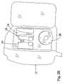
- FIG. 2Ais a side view of the administration feeding set loaded to a flow control apparatus according to the present invention.
- FIG. 2Bis a side view of an embodiment of a flow control apparatus prior to loading the administration feeding set thereto according to the present invention
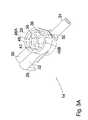
- FIG. 3Ais a partial perspective view of an embodiment of the valve mechanism shown in the feeding position according to the present invention.
- FIG. 3Bis a partial perspective view of the embodiment of the valve mechanism shown in the flushing position according to the present invention.
- FIG. 3Cis a perspective view of the embodiment of the valve mechanism shown in the blocking position according to the present invention.
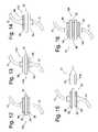
- FIG. 4is a side view of the embodiment of the valve mechanism according to the present invention.
- FIG. 5is an end view of the embodiment of the valve mechanism according to the present invention.
- FIG. 6is a cross-sectional view of the embodiment of the valve mechanism taken along line 6 - 6 of FIG. 5 according to the present invention
- FIG. 7is a cross-sectional view of the embodiment of the valve mechanism taken along line 7 - 7 of FIG. 4 according to the present invention.
- FIG. 8is a cross-sectional view of the embodiment of the valve mechanism taken along line 8 - 8 of FIG. 4 according to the present invention.
- FIG. 9is an opposing end view of the embodiment of the valve mechanism according to the present invention.
- FIG. 10is a bottom view of the embodiment of the valve mechanism according to the present invention.
- FIG. 11Ais a perspective view of an alternative embodiment of the valve mechanism shown in the feeding position according to the present invention.
- FIG. 11Bis a perspective view of the alternative embodiment of the valve mechanism shown in the blocking position according to the present invention.
- FIG. 12is a diagram of an embodiment of the mounting member with identification members attached to the lower and upper portions thereof according to the present invention.
- FIG. 13is a diagram of an embodiment of the mounting member with an identification member attached only to the lower portion thereof according to the present invention.
- FIG. 14is a diagram of an embodiment of the mounting member with an identification member attached only to the upper portion thereof according to the present invention.
- FIG. 15is a diagram of an embodiment of the mounting member with the identification members attached to the upper and lower portions and further illustrating the related sensor devices according to the present invention
- FIG. 16is a diagram of an alternative embodiment of a mounting member with identification members attached to upper, middle and lower portions according to the present invention.
- FIG. 17is a simplified block diagram illustrating the various systems related to the administration feeding set loaded to the flow control apparatus according to the present invention.
- FIG. 18is a flow chart of the software subsystem illustrating the process used to detect and identify a functional configuration of an administration feeding set adapted to be loaded to the flow control apparatus according to the present invention.
- an embodiment of the administration feeding set according to the present inventionis illustrated and generally indicated as 10 in FIG. 1 .
- This embodimentcomprises an administration feeding set 10 adapted to be loaded to a flow control apparatus 12 suitable for delivery of fluid to a patient.
- the administration feeding set 10comprises tubing 60 adapted for fluid flow communication and further adapted to engage the flow control apparatus 12 suitable for driving fluid through the tubing 60 .
- a valve mechanism 14is in direct communication with the tubing 60 and is adapted to permit or prevent fluid flow communication through the tubing 60 when valve mechanism 14 is engaged to the flow control apparatus 12 .
- the administration feeding set 10comprises a mounting member 16 in direct communication with the tubing 60 , wherein the mounting member 16 permits identification of the functional configuration of the administration feeding set 10 by the flow control apparatus 12 upon engagement of the mounting member 16 to the flow control apparatus 12 .
- the mounting member 16also assists in the loading of the administration feeding set 10 to the flow control apparatus 12 .
- the term loadmeans that the valve mechanism 14 and mounting member 16 are engaged to flow control apparatus 12 and tubing 60 is placed in a stretched condition between valve mechanism 14 and mounting member 16 such that the administration feeding set 10 is ready for operation with flow control apparatus 12 .
- the administration feeding set 10is identical to the previous embodiment with the exception that the valve mechanism 14 is absent.
- valve mechanism 14adapted to be engaged to flow control apparatus 12 .
- the valve mechanism 14is suitable for permitting or preventing fluid flow communication, as well as preventing disengagement of the valve mechanism 14 from flow control apparatus 12 when the valve mechanism 14 is in a position that permits fluid flow communication.
- the administration feeding set 10comprises tubing 60 that provides a fluid pathway between at least one source of fluid and a patient.
- Tubing 60comprises first tubing 86 engaged between the valve mechanism 14 and mounting member 16 , and second tubing 88 engaged between mounting member 16 and a connector 78 , such as a barbed connector, suitable for attachment to a gastrostomy device attached to a patient.
- the valve mechanism 14 and mounting member 16are adapted to engage the tubing 60 to the flow control apparatus 12 .
- tubing 60further comprises third tubing 82 engaged between a feeding fluid source 21 and valve mechanism 14 , and fourth tubing 84 engaged between a flushing fluid source 23 and valve mechanism 14 , wherein the valve mechanism 14 provides a means for permitting flow of feeding fluid or flushing fluid, or preventing fluid flow communication through tubing 60 .
- Flow control apparatus 12comprises a housing 20 that defines first and second recesses 22 and 24 adapted to load the administration feeding set 10 to flow control apparatus 12 .
- a means for driving fluid through tubing 60such as a rotor 26 , is operatively engaged to and through the housing 20 and is adapted to engage tubing 60 .
- Flow control apparatus 12further includes a sensor 17 ( FIG. 15 ) that detects the engagement of mounting member 16 to second recess 24 and is in operative communication with a software subsystem 15 as explained in greater detail below.
- valve mechanism 14 and rotor 26are operatively engaged to a gear arrangement 25 driven by a single motor source 27 .
- a suitable flow control apparatus 12is disclosed in co-pending patent application Ser. No. 10/854,136 filed on even date herewith and herein incorporated by reference in its entirety. However, it is understood that any suitable flow control apparatus 12 may be used with administration feeding set 10 .
- administration feeding set 10comprises tubing 60 engaged to valve mechanism 14 and mounting member 16 adapted for loading the administration feeding set 10 to flow control apparatus 12 .
- the valve mechanism 14is engaged to first recess 22 , the first tubing 86 then wrapped around rotor 26 , and the mounting member 16 engaged to second recess 24 such that first tubing 86 is placed in a stretched condition around rotor 26 and the administration feeding set 10 is ready for operation with flow control apparatus 12 .
- valve mechanism 14is engaged to the upstream portion of tubing 60 at first recess 22 and controls the flow of fluid from the respective fluid source through administration feeding set 10 , while the mounting member 16 is engaged to the downstream portion of tubing 60 at second recess 24 for loading the administration feeding set 10 to flow control apparatus 12 .
- the feeding fluid source 21 and the flushing fluid source 23are placed in fluid flow communication with valve mechanism 14 through tubing 60 for permitting or preventing fluid flow from either the feeding or flushing fluid sources 21 , 23 .
- valve mechanism 14is absent and a means (not shown) for controlling fluid flow through tubing 60 is positioned in an area other than on the administration feeding set 10 .
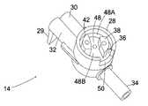
- the present inventionfurther relates to a valve mechanism 14 that comprises a valve body 28 having at least one inlet 30 , 32 in communication with an outlet 34 through a chamber 36 and a valve stem 38 rotatably disposed in the chamber 36 .
- the valve stem 38has a front portion 40 comprising a fluid pathway 44 defining at least one fluid port 46 .
- This embodiment of valve mechanism 14is suitable for controlling fluid flow.
- valve mechanism 14comprises a valve body 28 having at least one inlet 30 , 32 in communication with an outlet 34 through a chamber 36 with the valve body 28 further comprising a slot 50 .
- Valve stem 38is rotatably disposed in the chamber 36 with the valve stem 38 having a back portion 42 comprising a channel 48 .
- This embodiment of valve mechanism 14is suitable for preventing disengagement of the valve mechanism 14 from the flow control apparatus 12 when the valve mechanism 14 is in a position that permits fluid flow.
- valve mechanism 14comprises a valve body 28 having at least one inlet 30 , 32 in communication with an outlet 34 through a chamber 36 with the valve body 28 further comprising a slot 50 .
- Valve stem 38is rotatably disposed in the chamber 36 .
- the valve stem 38has a front portion 40 comprising a fluid pathway 44 defining at least one fluid port 46 and a back portion 42 comprising a channel 48 .
- This embodiment of valve mechanism 14is suitable for controlling fluid flow and for preventing disengagement of the valve mechanism 14 from the flow control apparatus 12 when the valve mechanism 14 is in a position that permits fluid flow.
- valve mechanism 14is adapted to be engaged to tubing 60 according to the present invention.
- valve mechanism 14comprises valve body 28 having a first inlet 30 adapted to be in communication with the feeding fluid source 21 through third tubing 82 and a second inlet 32 adapted to be in communication with a flushing fluid source 23 through fourth tubing 84 for providing fluid flow communication with an outlet 34 through chamber 36 interposed between first and second inlets 30 , 32 and outlet 34 .
- Valve body 28further comprises slot 50 along the periphery thereof that is a structural arrangement adapted to receive a rotatable shaft 33 therethrough for operating the valve mechanism 14 as shall be discussed below.
- valve body 28includes a tab 29 that enables the user to easily engage valve mechanism 14 to flow control apparatus 10 .
- valve stem 38has front portion 40 comprising a fluid pathway 44 that defines at least one fluid port 46 to establish fluid flow through valve body 28 . Fluid flow is established when valve stem 38 is rotated such that any one fluid port 46 is aligned with either the first or second inlets 30 and 32 , thereby establishing fluid flow communication between first or second inlets 30 , 32 and outlet 34 .
- channel 48has opposed openings 48 A and 48 B adapted to engage rotatable shaft 33 when engaging the valve mechanism 14 to the first recess 22 of flow control apparatus 12 .
- flow control apparatus 12further comprises a gear arrangement 25 operatively engaged to rotatable shaft 33 that is driven by the single motor source 27 .
- the engagement between the valve mechanism 14 and the rotatable shaft 33is accomplished by rotating the valve stem 38 and orienting channel 48 such that one of the openings 48 A or 48 B is aligned with slot 50 that permits the shaft 33 to be inserted into the interior portion of channel 48 .
- Channel 48provides a means for preventing disengagement of valve mechanism 14 from flow control apparatus 12 when the channel 48 is rotated to an orientation that misaligns the channel 48 with slot 50 and places the valve mechanism 14 in a position that permits fluid flow communication through tubing 60 .
- valve mechanism 14permits disengagement from the flow control apparatus 12 when the channel 48 is rotated to an orientation that aligns one of the opposed openings 48 A or 48 B with slot 50 and places the valve mechanism 14 in a position that prevents fluid flow communication through tubing 60 . More particularly, valve mechanism 14 must be placed in a blocking position that rotates valve stem 38 such that fluid ports 46 are in misalignment with both the first and second inlets 30 , 32 to prevent fluid flow communication in order to disengage valve mechanism 14 from housing 20 .
- the flow control apparatus 12directs rotatable shaft 33 through gear arrangement 25 to rotate valve stem 38 such that the valve mechanism 14 is placed in a blocking position shown in FIG. 10C , channel 48 is aligned with slot 50 while shaft 33 is disengaged through slot 50 .
- valve mechanism 14is configured to prevent manual operation thereof by a user such that valve mechanism 14 can be operated only when engaged to the flow control apparatus 12 .
- valve stem 38must be engaged to shaft 33 in order to permit operation of the flow control apparatus 12 , thereby making valve mechanism 14 difficult to operate manually and particularly useful as a tamper-proof device.
- Flow control apparatus 12further includes a microprocessor 37 that controls the rotation of valve stem 38 so that either first inlet 30 or second inlet 32 is in alignment or misalignment with the fluid ports 46 when permitting or preventing fluid flow communication.
- a microprocessor 37controls the rotation of valve stem 38 so that either first inlet 30 or second inlet 32 is in alignment or misalignment with the fluid ports 46 when permitting or preventing fluid flow communication.
- Valve stem 38is rotated in only one direction, for example counter-clockwise, such that the valve stem 38 rotates the fluid pathway 44 in one direction only when aligning or misaligning any one of the fluid ports 46 with either first or second inlets 30 , 32 , thereby permitting a one-way, multiple engagement operation between the fluid ports 46 and first and second inlets 30 , 32 that either permits or prevents fluid flow communication.
- valve stem 38aligns any one of fluid ports 46 with either first or second inlets 30 , 32 , fluid flow communication is established between either first or second inlets 30 , 32 and outlet 34 .
- valve mechanism 14 Ais similar in structure and operation to the preferred embodiment of valve mechanism 14 , except there is only a single feeding inlet 63 for providing feeding fluid through the administration feeding set 10 from the feeding fluid source 21 , rather than first and second inlets 30 , 32 which permit both feeding and flushing functions. Accordingly, valve mechanism 14 A alternates between a feeding position ( FIG. 11A ) for providing fluid to a patient and a blocking position ( FIG. 11B ) that prevents fluid flow communication.
- mounting member 16assists in loading the administration feeding set 10 to the flow control apparatus 12 and is in operative communication with software subsystem 15 when engaged to second recess 24 which provides a means for identifying the type of administration feeding set 10 .
- mounting member 16has an upper portion 52 and a lower portion 54 each adapted to receive an identification member 56 when attached thereto.
- mounting member 16has a cylindrical shape that concentrically surrounds tubing 60 and is configured to be engaged to second recess 24 when loading administration feeding set 10 to flow control apparatus 12 such that sensor 17 detects the presence of one or more identification members 56 attached to mounting member 16 .
- Sensor 17is preferably a Hall-effect sensor or other type of proximity sensor that is positioned near the second recess 24 such that sensor 17 can detect the presence of one or more identification members 56 when the mounting member 16 is engaged to second recess 24 .
- mounting member 16When mounting member 16 is engaged to second recess 24 , the attachment of one or more identification members 56 to mounting member 16 provides a means for allowing software subsystem 15 to identify the functional configuration of the administration feeding set 10 loaded to flow control apparatus 12 and detected by sensor 17 .
- mounting member 16has at least one or more identification members 56 attached thereto in accordance with an identification scheme that permits software subsystem 15 to identify the functional configuration of the administration feeding set 10 loaded to flow control apparatus 12 .
- identification members 56are magnetic components or, in the alternative, magnetically-susceptible metallic components capable of detection by sensor 17 without requiring direct physical contact with sensor 17 .
- microprocessor 37In order to identify the functional configuration of the administration feeding set 10 loaded to flow control apparatus 12 microprocessor 37 is operatively associated with a database 134 containing one or more identification schemes for identifying different functional configurations for an administration feeding set 10 .
- an identification member 56may be attached to the upper portion 52 , lower portion 54 , or both portions 52 and 54 of mounting member 16 .
- the attachment of at least one identification member 56 to the mounting member 16will vary to correspond with the number of different functional configurations.
- Each different functional configuration for an administration feeding set 10will have a predetermined number and location of identification member(s) 56 attached to mounting member 16 that identifies the administration feeding set 10 , such as feeding, flushing or re-certification, when mounting member 16 is detected by the sensor 17 and this data is communicated to the software subsystem 15 through microprocessor 37 .
- sensor 17detects the location and number of identification member(s) 56 when mounting member 16 is engaged to second recess 24 ; and second, software subsystem 15 that is in operative communication with sensor 17 determines the functional configuration of the loaded administration feeding set 10 based on the location and number of identification members 56 detected on mounting member 16 as shall be explained in greater detail below.
- sensor 17for use with an embodiment of the software subsystem 15 , comprises a pair of sensor devices 17 A and 17 B that detect the location and number of one or more identification members 56 attached to mounting member 16 .
- Sensor 17can be any known type of proximity sensor for detecting an identification member 56 , preferably a magnetic component, or in the alternative a magnetically-susceptible metallic component, attached to mounting member 16 .
- sensor 17may also comprise any number of sensor devices with each sensor device corresponding to a portion of the mounting member 16 for detecting the presence of an identification member 56 .
- a pair of magnetic field proximity sensors or magnetic switch-type sensorsmay be provided, although the present invention contemplates that other types of sensors may be used, such as various inductive coil arrangements.
- Sensor 17is positioned near to second recess 24 such that each sensor device 17 A and 17 B is positioned relative to a corresponding portion in close proximity with mounting member 16 when administration feeding set 10 is loaded to flow control apparatus 12 .
- sensor 17 A and sensor 17 Bare capable of detecting the presence of an identification member 56 attached to the corresponding upper and lower portions 52 and 54 of mounting member 16 .
- sensor devices 17 A and 17 Bare positioned near the second recess 24 in proximity to the upper and lower portions 52 and 54 of the mounting member 16 and are capable of detecting a corresponding identification member 56 attached to portions 52 and 54 , respectively. Accordingly, sensor device 17 A is placed in a position to detect an identification member 56 attached to only on upper portion 52 of mounting member 16 , while sensor device 17 B is positioned to detect the presence of an identification member 56 attached only to the lower portion 54 of mounting member 16 . As noted above, the present invention contemplates that a corresponding sensor device 17 is provided for each additional portion of mounting member 16 adapted to receive an identification member 56 .
- software subsystem 15provides a means for allowing the flow control apparatus 12 to identify the functional configuration of administration feeding set 10 loaded to flow control apparatus 12 .
- FIG. 18illustrates the sequence of steps software subsystem 15 executes through microprocessor 37 to identify a functional configuration of administration feeding set 10 loaded to flow control apparatus 12 from a plurality of functional configurations.
- software subsystem 15determines whether or not an administration feeding set 10 is loaded to flow control apparatus 12 . If the administration feeding set 10 is not loaded, then at step 324 the flow control apparatus 12 remains inoperative. However, if the administration feeding set 10 is loaded to flow control apparatus 12 , the administration feeding set 10 and flow control apparatus are ready for operation once software subsystem 15 then identifies the functional configuration of administration feeding set 10 being loaded to flow control apparatus 12 .
- microprocessor 37directs the flow control apparatus 12 to display an indication of such engagement to the user.
- software subsystem 15determines what functional configuration of administration feeding set 10 is loaded to the flow control apparatus 12 and ready for operation.
- software subsystem 15executes a series of decision points 322 , 326 , and 328 . At each of these decision points software subsystem 15 compares the number and placement of identification member 56 detected by sensor 17 with data stored in database 134 .
- microprocessor 37directs that this information be displayed on user interface 40 .
- software subsystem 15is able to not only detect that the administration feeding set 10 is loaded, but also determine and display the functional configuration of the administration feeding set 10 , such as feeding, flushing or re-certification loaded to the flow control apparatus 12 .
- the present inventioncontemplates that alternate arrangements for placement of an identification member 56 attached to upper and lower portions 52 , 54 may correspond to different functional configurations for administration feeding set 10 .
- an identification member 56may be attached to three different portions of a mounting member 16 A, which increases the total number of functional configurations capable of being detected by the sensor 17 from three to seven configurations.
- the present inventionfurther contemplates that increasing the number of portions on mounting member 16 A for engaging an identification member 56 increases the number of different functional configurations for administration feeding set 10 that can be detected and identified by flow control apparatus 12 .
- mounting member 16 Amay be a concentric sleeve having at least three separate portions with each portion adapted to receive an identification member 56 according to one or more identification schemes.
- mounting member 16 Apreferably has a middle portion 58 in addition to the upper and lower portions 52 , 54 that are each adapted to receive an identification member 56 .
- the polarity on any number of identification members 56may be reversed using techniques known in the art in order to provide another means of detecting one or more identification members 56 attached to mounting member 16 .
Landscapes
- Health & Medical Sciences (AREA)
- Life Sciences & Earth Sciences (AREA)
- Animal Behavior & Ethology (AREA)
- General Health & Medical Sciences (AREA)
- Public Health (AREA)
- Veterinary Medicine (AREA)
- Heart & Thoracic Surgery (AREA)
- Biomedical Technology (AREA)
- Engineering & Computer Science (AREA)
- Anesthesiology (AREA)
- Hematology (AREA)
- Vascular Medicine (AREA)
- Pulmonology (AREA)
- Infusion, Injection, And Reservoir Apparatuses (AREA)
- Preventing Unauthorised Actuation Of Valves (AREA)
- Feeding And Watering For Cattle Raising And Animal Husbandry (AREA)
- Ultra Sonic Daignosis Equipment (AREA)
- Medical Preparation Storing Or Oral Administration Devices (AREA)
- Quick-Acting Or Multi-Walled Pipe Joints (AREA)
- Devices For Dispensing Beverages (AREA)
Abstract
Description
X=2n−1
Wherein X is the number of potential different functional configurations and n is the number of portions along mounting
Claims (23)
Priority Applications (34)
| Application Number | Priority Date | Filing Date | Title |
|---|---|---|---|
| US10/853,958US7462170B2 (en) | 2004-05-25 | 2004-05-25 | Administration feeding set and valve mechanism |
| CA2565366ACA2565366C (en) | 2004-05-25 | 2005-05-25 | Administration feeding set and valve mechanism |
| PCT/US2005/018343WO2005115501A2 (en) | 2004-05-25 | 2005-05-25 | Administration feeding set and valve mechanism |
| EP09173821.1AEP2140895B1 (en) | 2004-05-25 | 2005-05-25 | Administration feeding set |
| KR1020087001948AKR100907764B1 (en) | 2004-05-25 | 2005-05-25 | Dosing supply set |
| CN2008100812189ACN101306212B (en) | 2004-05-25 | 2005-05-25 | Administration feeding mechanism |
| EP09173818.7AEP2147692B1 (en) | 2004-05-25 | 2005-05-25 | Administration feeding set |
| TW98108480ATWI321477B (en) | 2004-05-25 | 2005-05-25 | Administration feeding set and method of identifying an administration feeding set |
| AU2005247479AAU2005247479B2 (en) | 2004-05-25 | 2005-05-25 | Administration feeding set and valve mechanism |
| TW94117206ATWI314870B (en) | 2004-05-25 | 2005-05-25 | Administration feeding set and valve mechanism |
| EP19199416.9AEP3620205A1 (en) | 2004-05-25 | 2005-05-25 | Administration feeding set and mounting member |
| AT05753418TATE556732T1 (en) | 2004-05-25 | 2005-05-25 | ADMINISTRATION SET AND VALVE MECHANISM |
| NZ577215ANZ577215A (en) | 2004-05-25 | 2005-05-25 | Administration feeding set and valve mechanism |
| CA2668921ACA2668921C (en) | 2004-05-25 | 2005-05-25 | Administration feeding set and valve mechanism |
| JP2007511728AJP4384689B2 (en) | 2004-05-25 | 2005-05-25 | Nutrition set and valve mechanism |
| EP20050753418EP1748810B1 (en) | 2004-05-25 | 2005-05-25 | Administration feeding set and valve mechanism |
| CN2008100812174ACN101306211B (en) | 2004-05-25 | 2005-05-25 | Administration feeding mechanism |
| RU2006145958ARU2429886C2 (en) | 2004-05-25 | 2005-05-25 | Drug feeding device (versions) |
| MXPA06012774AMXPA06012774A (en) | 2004-05-25 | 2005-05-25 | Administration feeding set and valve mechanism. |
| CN2005800167494ACN101076365B (en) | 2004-05-25 | 2005-05-25 | Drug delivery device and valve mechanism |
| BRPI0511534-5ABRPI0511534A (en) | 2004-05-25 | 2005-05-25 | food administrator set and valve mechanism |
| KR1020087001951AKR100909500B1 (en) | 2004-05-25 | 2005-05-25 | Medication Supply Set and Medication Supply Set Identification Method |
| ES05753418TES2387570T3 (en) | 2004-05-25 | 2005-05-25 | Feeding set for administration and valve mechanism |
| EP09173822.9AEP2140906B1 (en) | 2004-05-25 | 2005-05-25 | Valve mechanism to be used with an administration feeding set |
| IL178949AIL178949A (en) | 2004-05-25 | 2006-10-31 | Administration feeding set and valve mechanism |
| NO20065921ANO20065921L (en) | 2004-05-25 | 2006-12-20 | Administration supply set and valve mechanism. |
| US11/678,350US7753881B2 (en) | 2004-05-25 | 2007-02-23 | Administration feeding set |
| US11/961,158US7753883B2 (en) | 2004-05-25 | 2007-12-20 | Administration feeding set |
| JP2009105827AJP4482055B2 (en) | 2004-05-25 | 2009-04-24 | Nutrition set and valve mechanism |
| AU2009202064AAU2009202064B2 (en) | 2004-05-25 | 2009-05-26 | Administration feeding set and valve mechanism |
| IL201860AIL201860A (en) | 2004-05-25 | 2009-11-01 | Administration feeding set |
| US12/795,889US8034028B2 (en) | 2004-05-25 | 2010-06-08 | Administration feeding set |
| IL208221AIL208221A (en) | 2004-05-25 | 2010-09-19 | Administration feeding set |
| US13/245,087US8361024B2 (en) | 2004-05-25 | 2011-09-26 | Administration feeding set |
Applications Claiming Priority (1)
| Application Number | Priority Date | Filing Date | Title |
|---|---|---|---|
| US10/853,958US7462170B2 (en) | 2004-05-25 | 2004-05-25 | Administration feeding set and valve mechanism |
Related Child Applications (2)
| Application Number | Title | Priority Date | Filing Date |
|---|---|---|---|
| US11/678,350DivisionUS7753881B2 (en) | 2004-05-25 | 2007-02-23 | Administration feeding set |
| US11/961,158DivisionUS7753883B2 (en) | 2004-05-25 | 2007-12-20 | Administration feeding set |
Publications (2)
| Publication Number | Publication Date |
|---|---|
| US20050267418A1 US20050267418A1 (en) | 2005-12-01 |
| US7462170B2true US7462170B2 (en) | 2008-12-09 |
Family
ID=35426337
Family Applications (5)
| Application Number | Title | Priority Date | Filing Date |
|---|---|---|---|
| US10/853,958Expired - LifetimeUS7462170B2 (en) | 2004-05-25 | 2004-05-25 | Administration feeding set and valve mechanism |
| US11/678,350Expired - LifetimeUS7753881B2 (en) | 2004-05-25 | 2007-02-23 | Administration feeding set |
| US11/961,158Expired - LifetimeUS7753883B2 (en) | 2004-05-25 | 2007-12-20 | Administration feeding set |
| US12/795,889Expired - LifetimeUS8034028B2 (en) | 2004-05-25 | 2010-06-08 | Administration feeding set |
| US13/245,087Expired - LifetimeUS8361024B2 (en) | 2004-05-25 | 2011-09-26 | Administration feeding set |
Family Applications After (4)
| Application Number | Title | Priority Date | Filing Date |
|---|---|---|---|
| US11/678,350Expired - LifetimeUS7753881B2 (en) | 2004-05-25 | 2007-02-23 | Administration feeding set |
| US11/961,158Expired - LifetimeUS7753883B2 (en) | 2004-05-25 | 2007-12-20 | Administration feeding set |
| US12/795,889Expired - LifetimeUS8034028B2 (en) | 2004-05-25 | 2010-06-08 | Administration feeding set |
| US13/245,087Expired - LifetimeUS8361024B2 (en) | 2004-05-25 | 2011-09-26 | Administration feeding set |
Country Status (17)
| Country | Link |
|---|---|
| US (5) | US7462170B2 (en) |
| EP (5) | EP2140895B1 (en) |
| JP (2) | JP4384689B2 (en) |
| KR (2) | KR100907764B1 (en) |
| CN (3) | CN101306211B (en) |
| AT (1) | ATE556732T1 (en) |
| AU (2) | AU2005247479B2 (en) |
| BR (1) | BRPI0511534A (en) |
| CA (2) | CA2668921C (en) |
| ES (1) | ES2387570T3 (en) |
| IL (3) | IL178949A (en) |
| MX (1) | MXPA06012774A (en) |
| NO (1) | NO20065921L (en) |
| NZ (1) | NZ577215A (en) |
| RU (1) | RU2429886C2 (en) |
| TW (2) | TWI314870B (en) |
| WO (1) | WO2005115501A2 (en) |
Cited By (26)
| Publication number | Priority date | Publication date | Assignee | Title |
|---|---|---|---|---|
| US20070093775A1 (en)* | 2005-10-20 | 2007-04-26 | Sherwood Services Ag | Connector for enteral fluid delivery set |
| US20100211022A1 (en)* | 2009-02-19 | 2010-08-19 | Tyco Healthcare Group Lp | Manual valve actuator for medical fluid delivery set |
| US20100249722A1 (en)* | 2004-05-25 | 2010-09-30 | Covidien Ag | Administration Feeding Set |
| EP2248507A2 (en) | 2009-05-07 | 2010-11-10 | Tyco Healthcare Group LP | Medical fluid container |
| US20100305508A1 (en)* | 2009-05-27 | 2010-12-02 | Cardinal Health 303, Inc. | Intravenous piston pump disposable & mechanism |
| US7896859B2 (en)* | 2005-10-20 | 2011-03-01 | Tyco Healthcare Group Lp | Enteral feeding set |
| US8052642B2 (en) | 2006-03-02 | 2011-11-08 | Covidien Ag | Pumping apparatus with secure loading features |
| US8052643B2 (en) | 2006-03-02 | 2011-11-08 | Tyco Healthcare Group Lp | Enteral feeding set and interlock device therefor |
| US8053721B2 (en) | 2006-12-11 | 2011-11-08 | Tyco Healthcare Group Lp | Pump set and pump with electromagnetic radiation operated interlock |
| US8142404B2 (en) | 2006-03-02 | 2012-03-27 | Covidien Ag | Controller for pumping apparatus |
| US8142399B2 (en) | 2006-03-02 | 2012-03-27 | Tyco Healthcare Group Lp | Pump set with safety interlock |
| US8154274B2 (en) | 2010-05-11 | 2012-04-10 | Tyco Healthcare Group Lp | Safety interlock |
| US8277196B2 (en) | 2010-06-11 | 2012-10-02 | Tyco Healthcare Group Lp | Adaptive accuracy for enteral feeding pump |
| CN102908258A (en)* | 2012-10-30 | 2013-02-06 | 江苏康诺医疗器械有限公司 | Nutritional liquid feeding device for clinical patient |
| CN102908252A (en)* | 2012-10-30 | 2013-02-06 | 江苏康诺医疗器械有限公司 | Medical feeding bag |
| CN103054720A (en)* | 2011-10-22 | 2013-04-24 | 江苏康诺医疗器械有限公司 | Food feeding bag |
| US8529511B2 (en) | 2007-01-05 | 2013-09-10 | Covidien Lp | Pump set with secure loading features and related methods therefor |
| WO2015038588A1 (en) | 2013-09-10 | 2015-03-19 | Covidien Lp | Enteral feeding pump with acceleration sensor |
| US20160121096A1 (en)* | 2014-10-30 | 2016-05-05 | Q-Core Medical Ltd. | Apparatus and systems for medical devices and corresponding interface units and methods for producing and operating the same |
| US9710610B2 (en) | 2012-07-25 | 2017-07-18 | Covidien Lp | Enteral feeding pump with flow adjustment |
| US9770554B2 (en) | 2011-09-13 | 2017-09-26 | Quest Medical, Inc. | Cardioplegia apparatus and method |
| US9852263B2 (en) | 2013-09-24 | 2017-12-26 | Covidien Lp | Feeding set and enteral feeding pump |
| US20220016397A1 (en)* | 2020-07-16 | 2022-01-20 | Intervene, Inc. | Intravascular devices and methods for delivery of fluids and therapeutic agents into blood vessel walls and intravascular structures |
| USD977093S1 (en) | 2020-07-30 | 2023-01-31 | Medline Industries, Lp | Conduit |
| US11759402B2 (en) | 2018-06-29 | 2023-09-19 | Generica Medical International, Inc. | Enteral feeding systems and methods |
| US11766552B2 (en) | 2020-07-30 | 2023-09-26 | Medline Industries, Lp | Conduit connectors and fluid assemblies for enteral feed pumps, and methods thereof |
Families Citing this family (40)
| Publication number | Priority date | Publication date | Assignee | Title |
|---|---|---|---|---|
| US7608059B2 (en)* | 2004-05-25 | 2009-10-27 | Covidien Ag | Flow control apparatus |
| US20060042631A1 (en)* | 2004-08-31 | 2006-03-02 | Martin James F | Apparatus to deliver oxygen to a patient |
| US7846131B2 (en)* | 2005-09-30 | 2010-12-07 | Covidien Ag | Administration feeding set and flow control apparatus with secure loading features |
| US7758551B2 (en)* | 2006-03-02 | 2010-07-20 | Covidien Ag | Pump set with secure loading features |
| US8795225B2 (en)* | 2008-09-29 | 2014-08-05 | Covidien Lp | Fluid detection in an enteral feeding set |
| KR101065359B1 (en)* | 2009-02-02 | 2011-09-16 | 주식회사 우영메디칼 | Chemical liquid injection multi controller |
| WO2010121741A1 (en) | 2009-04-23 | 2010-10-28 | Fresenius Medical Care Deutschland Gmbh | Valve device, valve core, external functional device, treatment device as well as method |
| CN101869731B (en)* | 2010-06-01 | 2013-01-16 | 深圳市深科医疗器械技术开发有限公司 | Infusion pump and control method thereof |
| CN101869730B (en)* | 2010-06-01 | 2013-01-16 | 深圳市深科医疗器械技术开发有限公司 | Infusion tube |
| WO2011150558A1 (en)* | 2010-06-02 | 2011-12-08 | 深圳市深科医疗器械技术开发有限公司 | Infusion tube |
| WO2011150560A1 (en)* | 2010-06-02 | 2011-12-08 | 深圳市深科医疗器械技术开发有限公司 | Infusion pump and controlling method thereof |
| ITBO20110289A1 (en)* | 2011-05-20 | 2012-11-21 | Health Robotics Srl | CONTAINMENT BOX OF A BAG FOR PHARMACEUTICALS |
| JP2014527881A (en)* | 2011-09-21 | 2014-10-23 | ベイヤー メディカル ケア インク. | Continuous multi-fluid pump device, drive and actuation system and method |
| US8475411B2 (en)* | 2011-11-10 | 2013-07-02 | B. Braun Medical, Inc. | Systems, kits, and methods for infusing fluids to a patient |
| CN103331187B (en)* | 2013-06-25 | 2015-07-15 | 益善生物技术股份有限公司 | Liquid transfer linking device |
| HRP20241397T1 (en) | 2014-01-10 | 2024-12-20 | Bayer Healthcare Llc | CONNECTOR FOR DISPOSABLE KIT |
| DE102014103507A1 (en) | 2014-03-14 | 2015-09-17 | Fresenius Medical Care Deutschland Gmbh | Medical functional device with a valve seat for a remanentes check valve |
| US10507319B2 (en) | 2015-01-09 | 2019-12-17 | Bayer Healthcare Llc | Multiple fluid delivery system with multi-use disposable set and features thereof |
| US10066981B2 (en)* | 2015-04-29 | 2018-09-04 | Kpr U.S., Llc | Detection of malfunction of flow monitoring system of flow control apparatus |
| TWI651107B (en) | 2016-06-15 | 2019-02-21 | 拜耳保健公司 | Multi-use disposable system and syringe therefor |
| US10366788B2 (en) | 2016-08-22 | 2019-07-30 | Curlin Medical Inc. | Administration set detection and authentication using cam profiles |
| AU2017332260B2 (en) | 2016-09-20 | 2022-10-20 | Bracco Diagnostics Inc. | Radioisotope delivery system with multiple detectors to detect gamma and beta emissions |
| EP3320929A1 (en)* | 2016-11-10 | 2018-05-16 | Sensile Pat AG | Drug delivery device |
| DE102017115862A1 (en)* | 2017-07-14 | 2019-01-17 | B. Braun Melsungen Ag | Device for controlling the opening and closing of a hose |
| CN108096035A (en)* | 2018-01-31 | 2018-06-01 | 深圳市贝斯曼精密仪器有限公司 | Feed pump |
| KR102733368B1 (en) | 2018-03-28 | 2024-11-21 | 브라코 다이어그노스틱스 아이엔씨. | Early detection of end-of-life of radioisotope generators |
| DK3776598T3 (en) | 2018-03-28 | 2022-08-01 | Bracco Diagnostics Inc | SYSTEMS AND TECHNIQUES FOR CALIBRATION OF RADIOISOTOPE DELIVERY SYSTEMS USING A GAMMA DETECTOR |
| AU2019390392B2 (en)* | 2018-11-26 | 2024-11-28 | Kpr U.S., Llc | Cassette for a flow control apparatus |
| CN109846716A (en)* | 2019-01-31 | 2019-06-07 | 浙江迈帝康医疗器械有限公司 | A kind of nutrition pump, infusion set, control valve and liquid control method |
| US20200352827A1 (en)* | 2019-05-07 | 2020-11-12 | iMed Technology, Inc. | Enteral feeding pump and tubing set |
| JP7602489B2 (en)* | 2019-05-29 | 2024-12-18 | メルク パテント ゲゼルシャフト ミット ベシュレンクテル ハフツング | Holding device and apparatus for automated stopcock actuation - Patents.com |
| US11110036B2 (en)* | 2019-07-01 | 2021-09-07 | Medline Industries, Inc. | Feeding set and enteral feeding pump assembly |
| US11963934B2 (en) | 2021-05-27 | 2024-04-23 | Zevex, Inc. | Flow valve for use with enteral feeding pump flush module |
| US11896798B2 (en)* | 2021-08-18 | 2024-02-13 | Alcor Scientific, Inc. | Enteral feeding pump systems, valve assemblies therefor and fluid flow control methods for same |
| US11992464B2 (en) | 2021-08-18 | 2024-05-28 | Alcor Scientific Llc | Enteral feeding pump systems, valve assemblies therefor and fluid flow control methods for same |
| USD1069109S1 (en) | 2023-04-17 | 2025-04-01 | iMed Technology, Inc. | Feeding tube set inlet component |
| USD1055279S1 (en) | 2023-04-17 | 2024-12-24 | iMed Technology, Inc. | Feeding tube set inlet component |
| USD1032520S1 (en) | 2023-05-30 | 2024-06-25 | Alcor Scientific Llc | Twin port adapter |
| US20250099340A1 (en)* | 2023-09-26 | 2025-03-27 | Robert L. Palmerton | Adult Enteral Feeding System |
| US20250135096A1 (en)* | 2023-10-27 | 2025-05-01 | Medcaptain Medical Technology Co., Ltd. | Fluid delivery mechanism and nutrient pump |
Citations (65)
| Publication number | Priority date | Publication date | Assignee | Title |
|---|---|---|---|---|
| US3626938A (en) | 1970-06-30 | 1971-12-14 | Antonio A Versaci | Hemodialysis shunt valve device with body connecting means |
| US3896803A (en) | 1973-08-20 | 1975-07-29 | Betamite Electronic Devices | Valve controlled single needle blood processing systems |
| US3985133A (en) | 1974-05-28 | 1976-10-12 | Imed Corporation | IV pump |
| US4396385A (en) | 1980-12-05 | 1983-08-02 | Baxter Travenol Laboratories, Inc. | Flow metering apparatus for a fluid infusion system |
| US4460355A (en) | 1982-06-11 | 1984-07-17 | Ivac Corporation | Fluid pressure monitoring system |
| US4519792A (en) | 1982-12-06 | 1985-05-28 | Abbott Laboratories | Infusion pump system |
| US4557725A (en) | 1984-05-04 | 1985-12-10 | Oximetrix, Inc. | I. V. Pump cassette |
| US4604093A (en) | 1984-06-12 | 1986-08-05 | I-Flow Corporation | Apparatus and method for administering multiple fluid infusions |
| US4605396A (en) | 1985-02-25 | 1986-08-12 | Warner-Lambert Company | Gravity flow cassette with rotary valve |
| US4685910A (en) | 1986-01-21 | 1987-08-11 | Abbott Laboratories | Apparatus and method for delivering secondary fluids to a patient using an intravenous administration set feeding a primary fluid |
| US4710166A (en) | 1985-11-08 | 1987-12-01 | Quest Medical, Inc. | Automated drug additive infusion system |
| USD293129S (en) | 1985-06-10 | 1987-12-08 | Ivac Corporation | Drug delivery valve for IV fluid infusion system |
| US4714463A (en) | 1984-11-29 | 1987-12-22 | Minnesota Mining And Manufacturing Company | Sequence valve for piggyback IV administration with tube reversal prevention |
| US4789000A (en) | 1984-07-13 | 1988-12-06 | Aslanian Jerry L | Flow control device for administration |
| US4798590A (en) | 1983-11-22 | 1989-01-17 | Medical Technology Products, Inc. | Intravenous infusion pumping system including independent pump set |
| US4820268A (en) | 1986-11-05 | 1989-04-11 | Nikkiso Co., Ltd. | Transfusion apparatus |
| US4838856A (en) | 1987-07-02 | 1989-06-13 | Truckee Meadows Research & Development | Fluid infusion flow control system |
| US4840542A (en) | 1985-03-27 | 1989-06-20 | Quest Medical, Inc. | Infusion pump with direct pressure sensing |
| US4884103A (en) | 1986-10-17 | 1989-11-28 | Minolta Camera Kabushiki Kaisha | Programmed control device for copying machines and the like |
| US4898581A (en) | 1987-02-19 | 1990-02-06 | Pfrimmer-Viggo Gmbh & Co. Kg | Device for administering liquid |
| US4913703A (en) | 1987-09-30 | 1990-04-03 | Sherwood Medical Company | Safety interlock system for medical fluid pumps |
| US4915688A (en) | 1987-12-03 | 1990-04-10 | Baxter International Inc. | Apparatus for administering solution to a patient |
| US4950254A (en) | 1988-10-14 | 1990-08-21 | Corpak, Inc. | Valve means for enteral therapy administration set |
| US4955860A (en) | 1987-04-09 | 1990-09-11 | Ruano Miguel M | Volumetric pump for parenteral perfusion |
| US5057081A (en) | 1990-06-15 | 1991-10-15 | Sherwood Medical Company | Peristaltic infusion device |
| US5147313A (en) | 1990-10-22 | 1992-09-15 | Entracare Corporation | Medical fluid delivery system with uniquely configured pump unit and fluid delivery set |
| US5201711A (en) | 1987-09-30 | 1993-04-13 | Sherwood Medical Company | Safety interlock system for medical fluid pumps |
| US5213483A (en) | 1991-06-19 | 1993-05-25 | Strato Medical Corporation | Peristaltic infusion pump with removable cassette and mechanically keyed tube set |
| US5364364A (en)* | 1993-08-04 | 1994-11-15 | Ivac Corporation | Automatic flow control valve system |
| US5374251A (en) | 1993-04-14 | 1994-12-20 | Entracare | Medical fluid pump apparatus |
| US5374248A (en) | 1991-12-27 | 1994-12-20 | Cair L.G.L. | Infusion manifold |
| US5415641A (en) | 1991-04-01 | 1995-05-16 | Sherwood Medical Company | Drop detection method and apparatus |
| US5431627A (en) | 1993-11-12 | 1995-07-11 | Abbott Laboratories | Cassette identification system for use with a multi-program drug infusion pump |
| US5437642A (en) | 1991-04-23 | 1995-08-01 | Minnesota Mining And Manufacturing Company | Free flow prevention system for infusion pump |
| US5443453A (en) | 1994-04-21 | 1995-08-22 | Sherwood Medical Company | Stop-cock valve |
| US5499968A (en) | 1990-03-08 | 1996-03-19 | Macnaught Pty Limited | Flow controllers for fluid infusion sets |
| US5531697A (en) | 1994-04-15 | 1996-07-02 | Sims Deltec, Inc. | Systems and methods for cassette identification for drug pumps |
| US5562615A (en) | 1994-02-28 | 1996-10-08 | Corpak, Inc. | Free flow detector for an enternal feeding pump |
| US5569026A (en) | 1992-06-18 | 1996-10-29 | Storz Endoskop Gmbh | Tube pump in which tube can be inserted only in one direction |
| US5584671A (en)* | 1994-11-28 | 1996-12-17 | Sherwood Medical Company | Apparatus for delivering fluid to a patient |
| US5603353A (en) | 1995-11-17 | 1997-02-18 | Essman Screw Products, Inc. | Quick disconnect coupling |
| US5634907A (en) | 1994-12-22 | 1997-06-03 | Sandoz Nutrition Ltd. | System for detection of fluid infusion |
| US5681294A (en) | 1995-09-21 | 1997-10-28 | Abbott Laboratories | Fluid delivery set |
| US5704584A (en) | 1995-03-27 | 1998-01-06 | Zevex, Inc. | Pinch clip occluder for infusion sets |
| US5755683A (en) | 1995-06-07 | 1998-05-26 | Deka Products Limited Partnership | Stopcock valve |
| US5772637A (en) | 1995-06-07 | 1998-06-30 | Deka Products Limited Partnership | Intravenous-line flow-control system |
| US5807321A (en) | 1995-11-28 | 1998-09-15 | Merit Medical | System for electronically monitoring the delivery of contrast media |
| US5807333A (en) | 1995-09-21 | 1998-09-15 | Abbott Laboratories | Peristaltic pump and fluid delivery set |
| US5814015A (en) | 1995-02-24 | 1998-09-29 | Harvard Clinical Technology, Inc. | Infusion pump for at least one syringe |
| US5951510A (en) | 1997-04-11 | 1999-09-14 | Nestec S.A. | Pump system with error detection for clinical nutrition |
| US6042564A (en) | 1997-04-11 | 2000-03-28 | Nstec S.A. | System and method for administering two liquids |
| US6059544A (en) | 1995-12-01 | 2000-05-09 | Alcon Laboratories, Inc. | Identification system for a surgical cassette |
| US6142979A (en) | 1995-03-27 | 2000-11-07 | Zevex | Pinch clip occluder system for infusion sets |
| US6164921A (en) | 1998-11-09 | 2000-12-26 | Moubayed; Ahmad Maher | Curvilinear peristaltic pump having insertable tubing assembly |
| US6280440B1 (en) | 1998-05-13 | 2001-08-28 | Olympus Optical Co., Ltd. | Cautery apparatus |
| US6364857B1 (en) | 1995-06-07 | 2002-04-02 | Deka Products Limited Partnership | Cassette for intravenous-line flow-control system |
| US6368314B1 (en) | 1998-09-08 | 2002-04-09 | Disetronic Licensing Ag | Monitoring of the pressure of a product fluid to be administered in dosed amounts during infusion or injection |
| US20020120186A1 (en) | 2001-01-08 | 2002-08-29 | Keimel John G. | Sensor system |
| US20020138034A1 (en) | 2001-03-20 | 2002-09-26 | Derek Daw J. | System for enriching a bodily fluid with a gas |
| US20020151838A1 (en) | 2001-04-16 | 2002-10-17 | Beck Kent F. | Feeding set adaptor |
| US20020169424A1 (en) | 2000-05-11 | 2002-11-14 | Scott Miles | Apparatus and method for preventing free flow in an infusion line |
| US20030055375A1 (en) | 1999-12-17 | 2003-03-20 | Holst Peter A. | Method for compensating for pressure differences across valves in cassette type IV pump |
| US6641562B1 (en) | 2000-05-10 | 2003-11-04 | Hps Medical, Inc. | Apparatus and method of intravenous fluid infusion |
| US20050267401A1 (en) | 2004-05-25 | 2005-12-01 | Sherwood Services, Ag. | Safety interlock system for an enteral feeding pump |
| US7092797B2 (en) | 2004-05-25 | 2006-08-15 | Sherwood Services Ag | Flow monitoring system for a flow control apparatus |
Family Cites Families (54)
| Publication number | Priority date | Publication date | Assignee | Title |
|---|---|---|---|---|
| US6241704B1 (en)* | 1901-11-22 | 2001-06-05 | Sims Deltec, Inc. | Drug pump systems and methods |
| JPS58165867A (en)* | 1982-03-26 | 1983-09-30 | テルモ株式会社 | Medical bag and production thereof |
| US4573498A (en)* | 1984-03-29 | 1986-03-04 | General Signal Corporation | Ball valve |
| US4741736A (en) | 1986-12-10 | 1988-05-03 | I-Flow Corporation | Programmable infusion pump |
| US4850805A (en) | 1987-03-13 | 1989-07-25 | Critikon, Inc. | Pump control system |
| US4845487A (en) | 1987-07-20 | 1989-07-04 | Frantz Medical Development Ltd. | Pump system for enteral/parenteral fluid control and delivery |
| US4831866A (en) | 1987-11-09 | 1989-05-23 | Tokheim Corporation | Automatic meter proving and calibration system |
| US4919596A (en) | 1987-12-04 | 1990-04-24 | Pacesetter Infusion, Ltd. | Fluid delivery control and monitoring apparatus for a medication infusion system |
| CA1324935C (en)* | 1987-12-04 | 1993-12-07 | James L. Henke | Fluid delivery control and monitoring apparatus for a medication infusion system |
| US4850980A (en)* | 1987-12-04 | 1989-07-25 | Fisher Scientific Company | I.V. pump cassette |
| US4918973A (en) | 1988-03-18 | 1990-04-24 | Great Plains Industries, Inc. | Apparatus and method for calibrating a measuring device |
| AU635262B2 (en) | 1989-05-11 | 1993-03-18 | Bespak Plc | Pump apparatus for biomedical use |
| FR2651037B1 (en) | 1989-08-16 | 1991-10-25 | Hospal Ind | METHOD FOR CALIBRATING A PULSE RESPONSE FLOWMETER |
| US5084031A (en)* | 1989-09-12 | 1992-01-28 | Research Medical, Inc. | Cardioplegia three-way double stopcock |
| US5158437A (en) | 1990-03-15 | 1992-10-27 | Abbott Laboratories | Volumetric pump with spring-biased cracking valves |
| US5171029A (en) | 1990-04-26 | 1992-12-15 | Minnesota Mining And Manufacturing Company | Seal construction for pump apparatus |
| US5098261A (en) | 1990-05-04 | 1992-03-24 | Brandel Corporation | Peristaltic pump and method for adjustable flow regulation |
| DE4020522A1 (en)* | 1990-06-28 | 1992-01-09 | Fresenius Ag | Medical equipment system with identification of one-time use articles - uses electrical resistors with values specifying types and sizes |
| US5197322A (en) | 1990-11-29 | 1993-03-30 | Minimed Technologies, Ltd. | Pressure reservoir filling process for an implantable medication infusion pump |
| DE4042101C2 (en) | 1990-12-28 | 1996-09-19 | Medical Support Gmbh | Testing device for syringe and infusion pumps |
| US5181910A (en) | 1991-02-28 | 1993-01-26 | Pharmacia Deltec, Inc. | Method and apparatus for a fluid infusion system with linearized flow rate change |
| DE4111965C2 (en) | 1991-04-12 | 2000-03-23 | Draegerwerk Ag | Method for calibrating a flow sensor in a breathing system |
| US5299446A (en) | 1991-06-28 | 1994-04-05 | Abbott Laboratories | Method and apparatus for calibrating a multiple port pump |
| US5244463A (en) | 1991-12-06 | 1993-09-14 | Block Medical, Inc. | Programmable infusion pump |
| DE4232082A1 (en) | 1992-09-25 | 1994-03-31 | Ruesch Willy Ag | stopcock |
| US5368562A (en) | 1993-07-30 | 1994-11-29 | Pharmacia Deltec, Inc. | Systems and methods for operating ambulatory medical devices such as drug delivery devices |
| US5439452A (en)* | 1994-01-31 | 1995-08-08 | Children's Medical Ventures, Inc. | Limit stop valve infusion device |
| US5443543A (en) | 1994-09-21 | 1995-08-22 | Colt's Manufacturing Company Inc. | Firearm barrel assembly with removable sight |
| NL9500612A (en)* | 1995-03-30 | 1996-11-01 | Cordis Europ | Stop valve for medical application |
| US5531680A (en) | 1995-05-05 | 1996-07-02 | Zevex, Inc. | Enteral feeding pump motor unit and method of use |
| US5589026A (en)* | 1995-06-02 | 1996-12-31 | Minnesota Mining And Manufacturing Company | Method and apparatus for adhering object to a glass surface |
| US6250130B1 (en) | 1995-07-10 | 2001-06-26 | Bayer Corporation | Method and apparatus for monitoring an aspirating and dispensing system |
| EP0874659A4 (en)* | 1995-12-04 | 1999-12-08 | Alphamed Inc | Infusion pump with disposable tubing and size indicating means |
| JP3439630B2 (en)* | 1997-06-11 | 2003-08-25 | 株式会社クボタ | Operating cap for direct buried valve |
| SE510286C2 (en) | 1997-09-22 | 1999-05-10 | Gambro Med Tech Ab | Method and Device for Monitoring Infusion Pump in a Hemo or Hemodia Filtration Machine |
| US6457488B2 (en)* | 1998-01-08 | 2002-10-01 | George Loo | Stopcock having axial port for syringe twist actuation |
| CN1105850C (en)* | 1998-06-29 | 2003-04-16 | 斯冈株式会社 | Channel Switching apparatus |
| US6422057B1 (en) | 1998-09-29 | 2002-07-23 | Deltec, Inc. | Drug pump testing system and methods |
| US6117115A (en) | 1998-10-12 | 2000-09-12 | B. Braun Medical, Inc. | Medical tubing slide clamp device for determining proper tubing size and functional characteristics |
| US6283719B1 (en) | 1998-11-05 | 2001-09-04 | Frantz Medical Development Ltd | Detecting obstructions in enteral/parenteral feeding tubes and automatic removal of clogs therefrom |
| US7721948B1 (en)* | 1999-05-25 | 2010-05-25 | Silverbrook Research Pty Ltd | Method and system for online payments |
| US6638263B1 (en) | 1999-10-12 | 2003-10-28 | Durect Corporation | Regulation of drug delivery through flow diversion |
| JP2001129084A (en)* | 1999-11-01 | 2001-05-15 | Kawasumi Lab Inc | Clamps and medical tools |
| US6461335B1 (en)* | 2000-02-28 | 2002-10-08 | Sherwood Services, Ag | Tube dependent anti-free-flow valve |
| US6491659B1 (en) | 2000-03-02 | 2002-12-10 | Isshin Miyamoto | Liquid flow rate controller |
| US6626862B1 (en)* | 2000-04-04 | 2003-09-30 | Acist Medical Systems, Inc. | Fluid management and component detection system |
| US6985870B2 (en) | 2002-01-11 | 2006-01-10 | Baxter International Inc. | Medication delivery system |
| US6880808B2 (en)* | 2002-05-03 | 2005-04-19 | Acist Medical Systems, Inc. | Gamma-stable high pressure stopcock |
| ITMI20021895A1 (en)* | 2002-09-06 | 2004-03-07 | Gambro Lundia Ab | FLOW INTERCEPTION BODY. |
| JP2006500154A (en)* | 2002-09-26 | 2006-01-05 | シャーウッド・サービシーズ・アクチェンゲゼルシャフト | Enteral nutrition system and administration nutrition set |
| SE526008C2 (en)* | 2002-10-10 | 2005-06-14 | Medical Vision Res & Dev Ab | Medical-technical identification device |
| US7462170B2 (en)* | 2004-05-25 | 2008-12-09 | Covidien Ag | Administration feeding set and valve mechanism |
| US7608059B2 (en) | 2004-05-25 | 2009-10-27 | Covidien Ag | Flow control apparatus |
| US7794423B2 (en) | 2004-05-25 | 2010-09-14 | Covidien Ag | Re-certification system for a flow control apparatus |
- 2004
- 2004-05-25USUS10/853,958patent/US7462170B2/ennot_activeExpired - Lifetime
- 2005
- 2005-05-25EPEP09173821.1Apatent/EP2140895B1/ennot_activeExpired - Lifetime
- 2005-05-25CACA2668921Apatent/CA2668921C/ennot_activeExpired - Lifetime
- 2005-05-25TWTW94117206Apatent/TWI314870B/ennot_activeIP Right Cessation
- 2005-05-25EPEP09173822.9Apatent/EP2140906B1/ennot_activeExpired - Lifetime
- 2005-05-25EPEP19199416.9Apatent/EP3620205A1/ennot_activeWithdrawn
- 2005-05-25MXMXPA06012774Apatent/MXPA06012774A/enactiveIP Right Grant
- 2005-05-25BRBRPI0511534-5Apatent/BRPI0511534A/ennot_activeIP Right Cessation
- 2005-05-25EPEP20050753418patent/EP1748810B1/ennot_activeExpired - Lifetime
- 2005-05-25CNCN2008100812174Apatent/CN101306211B/ennot_activeExpired - Lifetime
- 2005-05-25KRKR1020087001948Apatent/KR100907764B1/ennot_activeExpired - Lifetime
- 2005-05-25WOPCT/US2005/018343patent/WO2005115501A2/enactiveApplication Filing
- 2005-05-25CACA2565366Apatent/CA2565366C/ennot_activeExpired - Lifetime
- 2005-05-25CNCN2008100812189Apatent/CN101306212B/ennot_activeExpired - Lifetime
- 2005-05-25NZNZ577215Apatent/NZ577215A/enunknown
- 2005-05-25ESES05753418Tpatent/ES2387570T3/ennot_activeExpired - Lifetime
- 2005-05-25TWTW98108480Apatent/TWI321477B/ennot_activeIP Right Cessation
- 2005-05-25AUAU2005247479Apatent/AU2005247479B2/ennot_activeExpired
- 2005-05-25CNCN2005800167494Apatent/CN101076365B/ennot_activeExpired - Lifetime
- 2005-05-25ATAT05753418Tpatent/ATE556732T1/enactive
- 2005-05-25RURU2006145958Apatent/RU2429886C2/ennot_activeIP Right Cessation
- 2005-05-25EPEP09173818.7Apatent/EP2147692B1/ennot_activeExpired - Lifetime
- 2005-05-25JPJP2007511728Apatent/JP4384689B2/ennot_activeExpired - Lifetime
- 2005-05-25KRKR1020087001951Apatent/KR100909500B1/ennot_activeExpired - Lifetime
- 2006
- 2006-10-31ILIL178949Apatent/IL178949A/enactiveIP Right Grant
- 2006-12-20NONO20065921Apatent/NO20065921L/ennot_activeApplication Discontinuation
- 2007
- 2007-02-23USUS11/678,350patent/US7753881B2/ennot_activeExpired - Lifetime
- 2007-12-20USUS11/961,158patent/US7753883B2/ennot_activeExpired - Lifetime
- 2009
- 2009-04-24JPJP2009105827Apatent/JP4482055B2/ennot_activeExpired - Lifetime
- 2009-05-26AUAU2009202064Apatent/AU2009202064B2/ennot_activeExpired
- 2009-11-01ILIL201860Apatent/IL201860A/enactiveIP Right Grant
- 2010
- 2010-06-08USUS12/795,889patent/US8034028B2/ennot_activeExpired - Lifetime
- 2010-09-19ILIL208221Apatent/IL208221A/enactiveIP Right Grant
- 2011
- 2011-09-26USUS13/245,087patent/US8361024B2/ennot_activeExpired - Lifetime
Patent Citations (66)
| Publication number | Priority date | Publication date | Assignee | Title |
|---|---|---|---|---|
| US3626938A (en) | 1970-06-30 | 1971-12-14 | Antonio A Versaci | Hemodialysis shunt valve device with body connecting means |
| US3896803A (en) | 1973-08-20 | 1975-07-29 | Betamite Electronic Devices | Valve controlled single needle blood processing systems |
| US3985133A (en) | 1974-05-28 | 1976-10-12 | Imed Corporation | IV pump |
| US4396385A (en) | 1980-12-05 | 1983-08-02 | Baxter Travenol Laboratories, Inc. | Flow metering apparatus for a fluid infusion system |
| US4460355A (en) | 1982-06-11 | 1984-07-17 | Ivac Corporation | Fluid pressure monitoring system |
| US4519792A (en) | 1982-12-06 | 1985-05-28 | Abbott Laboratories | Infusion pump system |
| US4798590A (en) | 1983-11-22 | 1989-01-17 | Medical Technology Products, Inc. | Intravenous infusion pumping system including independent pump set |
| US4557725A (en) | 1984-05-04 | 1985-12-10 | Oximetrix, Inc. | I. V. Pump cassette |
| US4604093A (en) | 1984-06-12 | 1986-08-05 | I-Flow Corporation | Apparatus and method for administering multiple fluid infusions |
| US4789000A (en) | 1984-07-13 | 1988-12-06 | Aslanian Jerry L | Flow control device for administration |
| US4714463A (en) | 1984-11-29 | 1987-12-22 | Minnesota Mining And Manufacturing Company | Sequence valve for piggyback IV administration with tube reversal prevention |
| US4605396A (en) | 1985-02-25 | 1986-08-12 | Warner-Lambert Company | Gravity flow cassette with rotary valve |
| US4840542A (en) | 1985-03-27 | 1989-06-20 | Quest Medical, Inc. | Infusion pump with direct pressure sensing |
| USD293129S (en) | 1985-06-10 | 1987-12-08 | Ivac Corporation | Drug delivery valve for IV fluid infusion system |
| US4710166A (en) | 1985-11-08 | 1987-12-01 | Quest Medical, Inc. | Automated drug additive infusion system |
| US4685910A (en) | 1986-01-21 | 1987-08-11 | Abbott Laboratories | Apparatus and method for delivering secondary fluids to a patient using an intravenous administration set feeding a primary fluid |
| US4884103A (en) | 1986-10-17 | 1989-11-28 | Minolta Camera Kabushiki Kaisha | Programmed control device for copying machines and the like |
| US4820268A (en) | 1986-11-05 | 1989-04-11 | Nikkiso Co., Ltd. | Transfusion apparatus |
| US4898581A (en) | 1987-02-19 | 1990-02-06 | Pfrimmer-Viggo Gmbh & Co. Kg | Device for administering liquid |
| US4955860A (en) | 1987-04-09 | 1990-09-11 | Ruano Miguel M | Volumetric pump for parenteral perfusion |
| US4838856A (en) | 1987-07-02 | 1989-06-13 | Truckee Meadows Research & Development | Fluid infusion flow control system |
| US4913703A (en) | 1987-09-30 | 1990-04-03 | Sherwood Medical Company | Safety interlock system for medical fluid pumps |
| US4913703B1 (en) | 1987-09-30 | 1992-06-16 | Pasqualucci Joseph | |
| US5201711A (en) | 1987-09-30 | 1993-04-13 | Sherwood Medical Company | Safety interlock system for medical fluid pumps |
| US4915688A (en) | 1987-12-03 | 1990-04-10 | Baxter International Inc. | Apparatus for administering solution to a patient |
| US4950254A (en) | 1988-10-14 | 1990-08-21 | Corpak, Inc. | Valve means for enteral therapy administration set |
| US5499968A (en) | 1990-03-08 | 1996-03-19 | Macnaught Pty Limited | Flow controllers for fluid infusion sets |
| US5057081A (en) | 1990-06-15 | 1991-10-15 | Sherwood Medical Company | Peristaltic infusion device |
| US5147313A (en) | 1990-10-22 | 1992-09-15 | Entracare Corporation | Medical fluid delivery system with uniquely configured pump unit and fluid delivery set |
| US5415641A (en) | 1991-04-01 | 1995-05-16 | Sherwood Medical Company | Drop detection method and apparatus |
| US5437642A (en) | 1991-04-23 | 1995-08-01 | Minnesota Mining And Manufacturing Company | Free flow prevention system for infusion pump |
| US5213483A (en) | 1991-06-19 | 1993-05-25 | Strato Medical Corporation | Peristaltic infusion pump with removable cassette and mechanically keyed tube set |
| US5374248A (en) | 1991-12-27 | 1994-12-20 | Cair L.G.L. | Infusion manifold |
| US5569026A (en) | 1992-06-18 | 1996-10-29 | Storz Endoskop Gmbh | Tube pump in which tube can be inserted only in one direction |
| US5374251A (en) | 1993-04-14 | 1994-12-20 | Entracare | Medical fluid pump apparatus |
| US5364364A (en)* | 1993-08-04 | 1994-11-15 | Ivac Corporation | Automatic flow control valve system |
| US5431627A (en) | 1993-11-12 | 1995-07-11 | Abbott Laboratories | Cassette identification system for use with a multi-program drug infusion pump |
| US5562615A (en) | 1994-02-28 | 1996-10-08 | Corpak, Inc. | Free flow detector for an enternal feeding pump |
| US5531697A (en) | 1994-04-15 | 1996-07-02 | Sims Deltec, Inc. | Systems and methods for cassette identification for drug pumps |
| US5443453A (en) | 1994-04-21 | 1995-08-22 | Sherwood Medical Company | Stop-cock valve |
| US5584671A (en)* | 1994-11-28 | 1996-12-17 | Sherwood Medical Company | Apparatus for delivering fluid to a patient |
| US5634907A (en) | 1994-12-22 | 1997-06-03 | Sandoz Nutrition Ltd. | System for detection of fluid infusion |
| US5814015A (en) | 1995-02-24 | 1998-09-29 | Harvard Clinical Technology, Inc. | Infusion pump for at least one syringe |
| US6142979A (en) | 1995-03-27 | 2000-11-07 | Zevex | Pinch clip occluder system for infusion sets |
| US5704584A (en) | 1995-03-27 | 1998-01-06 | Zevex, Inc. | Pinch clip occluder for infusion sets |
| US5755683A (en) | 1995-06-07 | 1998-05-26 | Deka Products Limited Partnership | Stopcock valve |
| US5772637A (en) | 1995-06-07 | 1998-06-30 | Deka Products Limited Partnership | Intravenous-line flow-control system |
| US6364857B1 (en) | 1995-06-07 | 2002-04-02 | Deka Products Limited Partnership | Cassette for intravenous-line flow-control system |
| US5681294A (en) | 1995-09-21 | 1997-10-28 | Abbott Laboratories | Fluid delivery set |
| US5807333A (en) | 1995-09-21 | 1998-09-15 | Abbott Laboratories | Peristaltic pump and fluid delivery set |
| US5603353A (en) | 1995-11-17 | 1997-02-18 | Essman Screw Products, Inc. | Quick disconnect coupling |
| US5807321A (en) | 1995-11-28 | 1998-09-15 | Merit Medical | System for electronically monitoring the delivery of contrast media |
| US6059544A (en) | 1995-12-01 | 2000-05-09 | Alcon Laboratories, Inc. | Identification system for a surgical cassette |
| US5951510A (en) | 1997-04-11 | 1999-09-14 | Nestec S.A. | Pump system with error detection for clinical nutrition |
| US6042564A (en) | 1997-04-11 | 2000-03-28 | Nstec S.A. | System and method for administering two liquids |
| US6280440B1 (en) | 1998-05-13 | 2001-08-28 | Olympus Optical Co., Ltd. | Cautery apparatus |
| US6368314B1 (en) | 1998-09-08 | 2002-04-09 | Disetronic Licensing Ag | Monitoring of the pressure of a product fluid to be administered in dosed amounts during infusion or injection |
| US6164921A (en) | 1998-11-09 | 2000-12-26 | Moubayed; Ahmad Maher | Curvilinear peristaltic pump having insertable tubing assembly |
| US20030055375A1 (en) | 1999-12-17 | 2003-03-20 | Holst Peter A. | Method for compensating for pressure differences across valves in cassette type IV pump |
| US6641562B1 (en) | 2000-05-10 | 2003-11-04 | Hps Medical, Inc. | Apparatus and method of intravenous fluid infusion |
| US20020169424A1 (en) | 2000-05-11 | 2002-11-14 | Scott Miles | Apparatus and method for preventing free flow in an infusion line |
| US20020120186A1 (en) | 2001-01-08 | 2002-08-29 | Keimel John G. | Sensor system |
| US20020138034A1 (en) | 2001-03-20 | 2002-09-26 | Derek Daw J. | System for enriching a bodily fluid with a gas |
| US20020151838A1 (en) | 2001-04-16 | 2002-10-17 | Beck Kent F. | Feeding set adaptor |
| US20050267401A1 (en) | 2004-05-25 | 2005-12-01 | Sherwood Services, Ag. | Safety interlock system for an enteral feeding pump |
| US7092797B2 (en) | 2004-05-25 | 2006-08-15 | Sherwood Services Ag | Flow monitoring system for a flow control apparatus |
Cited By (45)
| Publication number | Priority date | Publication date | Assignee | Title |
|---|---|---|---|---|
| US20120078196A1 (en)* | 2004-05-25 | 2012-03-29 | Covidien Ag | Administration feeding set |
| US20100249722A1 (en)* | 2004-05-25 | 2010-09-30 | Covidien Ag | Administration Feeding Set |
| US8361024B2 (en)* | 2004-05-25 | 2013-01-29 | Covidien Ag | Administration feeding set |
| US8034028B2 (en)* | 2004-05-25 | 2011-10-11 | Covidien Ag | Administration feeding set |
| US20110245771A1 (en)* | 2005-10-20 | 2011-10-06 | Tyco Healthcare Group Lp | Enteral Feeding Set |
| US7611502B2 (en) | 2005-10-20 | 2009-11-03 | Covidien Ag | Connector for enteral fluid delivery set |
| US8357136B2 (en)* | 2005-10-20 | 2013-01-22 | Covidien Lp | Enteral feeding set |
| US20070093775A1 (en)* | 2005-10-20 | 2007-04-26 | Sherwood Services Ag | Connector for enteral fluid delivery set |
| US7896859B2 (en)* | 2005-10-20 | 2011-03-01 | Tyco Healthcare Group Lp | Enteral feeding set |
| US8142404B2 (en) | 2006-03-02 | 2012-03-27 | Covidien Ag | Controller for pumping apparatus |
| US9402789B2 (en) | 2006-03-02 | 2016-08-02 | Covidien Ag | Pump set having secure loading features |
| US8052642B2 (en) | 2006-03-02 | 2011-11-08 | Covidien Ag | Pumping apparatus with secure loading features |
| US8052643B2 (en) | 2006-03-02 | 2011-11-08 | Tyco Healthcare Group Lp | Enteral feeding set and interlock device therefor |
| US8142399B2 (en) | 2006-03-02 | 2012-03-27 | Tyco Healthcare Group Lp | Pump set with safety interlock |
| US8053721B2 (en) | 2006-12-11 | 2011-11-08 | Tyco Healthcare Group Lp | Pump set and pump with electromagnetic radiation operated interlock |
| US8529511B2 (en) | 2007-01-05 | 2013-09-10 | Covidien Lp | Pump set with secure loading features and related methods therefor |
| EP2221084A1 (en) | 2009-02-19 | 2010-08-25 | Tyco Healthcare Group LP | Manual valve actuator for medical fluid delivery set |
| US9114243B2 (en) | 2009-02-19 | 2015-08-25 | Covidien Lp | Manual valve actuator for medical fluid delivery set |
| US20100211022A1 (en)* | 2009-02-19 | 2010-08-19 | Tyco Healthcare Group Lp | Manual valve actuator for medical fluid delivery set |
| US20100286650A1 (en)* | 2009-05-07 | 2010-11-11 | Alan Fitzgerald | Medical Fluid Container |
| EP2248507A2 (en) | 2009-05-07 | 2010-11-10 | Tyco Healthcare Group LP | Medical fluid container |
| US9566385B2 (en) | 2009-05-27 | 2017-02-14 | Carefusion 303, Inc. | Intravenous piston pump disposable and mechanism |
| US8733736B2 (en) | 2009-05-27 | 2014-05-27 | Carefusion 303, Inc. | Intravenous piston pump disposable and mechanism |
| US20100305508A1 (en)* | 2009-05-27 | 2010-12-02 | Cardinal Health 303, Inc. | Intravenous piston pump disposable & mechanism |
| WO2010138612A3 (en)* | 2009-05-27 | 2011-04-14 | Carefusion 303, Inc. | Intravenous piston pump disposable and mechanism |
| RU2552683C2 (en)* | 2009-05-27 | 2015-06-10 | Кэафьюжн 303, Инк. | Disposable piston pump and mechanism for intravenous infusion |
| US8760146B2 (en) | 2010-05-11 | 2014-06-24 | Covidien Lp | Safety interlock |
| US8154274B2 (en) | 2010-05-11 | 2012-04-10 | Tyco Healthcare Group Lp | Safety interlock |
| US8277196B2 (en) | 2010-06-11 | 2012-10-02 | Tyco Healthcare Group Lp | Adaptive accuracy for enteral feeding pump |
| US9770554B2 (en) | 2011-09-13 | 2017-09-26 | Quest Medical, Inc. | Cardioplegia apparatus and method |
| CN103054720A (en)* | 2011-10-22 | 2013-04-24 | 江苏康诺医疗器械有限公司 | Food feeding bag |
| US9710610B2 (en) | 2012-07-25 | 2017-07-18 | Covidien Lp | Enteral feeding pump with flow adjustment |
| CN102908258A (en)* | 2012-10-30 | 2013-02-06 | 江苏康诺医疗器械有限公司 | Nutritional liquid feeding device for clinical patient |
| CN102908252A (en)* | 2012-10-30 | 2013-02-06 | 江苏康诺医疗器械有限公司 | Medical feeding bag |
| WO2015038588A1 (en) | 2013-09-10 | 2015-03-19 | Covidien Lp | Enteral feeding pump with acceleration sensor |
| US11259992B2 (en) | 2013-09-24 | 2022-03-01 | Kpr U.S., Llc | Method of operating an enteral feeding pump |
| US9852263B2 (en) | 2013-09-24 | 2017-12-26 | Covidien Lp | Feeding set and enteral feeding pump |
| US10426709B2 (en) | 2013-09-24 | 2019-10-01 | Kpr U.S., Llc | Feeding set and enteral feeding pump |
| US12357542B2 (en) | 2013-09-24 | 2025-07-15 | Kpr U.S., Llc | Method for operating a feeding set and enteral feeding pump |
| US20160121096A1 (en)* | 2014-10-30 | 2016-05-05 | Q-Core Medical Ltd. | Apparatus and systems for medical devices and corresponding interface units and methods for producing and operating the same |
| US11759402B2 (en) | 2018-06-29 | 2023-09-19 | Generica Medical International, Inc. | Enteral feeding systems and methods |
| US20220016397A1 (en)* | 2020-07-16 | 2022-01-20 | Intervene, Inc. | Intravascular devices and methods for delivery of fluids and therapeutic agents into blood vessel walls and intravascular structures |
| USD977093S1 (en) | 2020-07-30 | 2023-01-31 | Medline Industries, Lp | Conduit |
| US11766552B2 (en) | 2020-07-30 | 2023-09-26 | Medline Industries, Lp | Conduit connectors and fluid assemblies for enteral feed pumps, and methods thereof |
| USD1006222S1 (en) | 2020-07-30 | 2023-11-28 | Medline Industries, Lp | Conduit |
Also Published As
Similar Documents
| Publication | Publication Date | Title |
|---|---|---|
| US7462170B2 (en) | Administration feeding set and valve mechanism | |
| CA2559950C (en) | Administration feeding set and flow control apparatus with secure loading features | |
| HK1139883A (en) | Administration feeding set and valve mechanism | |
| HK1139884A (en) | Administration feeding set | |
| KR100882036B1 (en) | Dosing supply set |
Legal Events
| Date | Code | Title | Description |
|---|---|---|---|
| AS | Assignment | Owner name:SHERWOOD SERVICES, AG, SWITZERLAND Free format text:ASSIGNMENT OF ASSIGNORS INTEREST;ASSIGNORS:FOURNIE, GLENN G.;HARR, JAMES;MEIER, KEVIN C.;AND OTHERS;REEL/FRAME:014819/0057 Effective date:20040629 | |
| AS | Assignment | Owner name:COVIDIEN AG, SWITZERLAND Free format text:CHANGE OF NAME;ASSIGNOR:SHERWOOD SERVICES AG;REEL/FRAME:021370/0774 Effective date:20070309 Owner name:COVIDIEN AG,SWITZERLAND Free format text:CHANGE OF NAME;ASSIGNOR:SHERWOOD SERVICES AG;REEL/FRAME:021370/0774 Effective date:20070309 | |
| STCF | Information on status: patent grant | Free format text:PATENTED CASE | |
| AS | Assignment | Owner name:TYCO HEALTHCARE GROUP AG,SWITZERLAND Free format text:MERGER;ASSIGNOR:COVIDIEN AG;REEL/FRAME:024483/0319 Effective date:20081215 Owner name:TYCO HEALTHCARE GROUP AG, SWITZERLAND Free format text:MERGER;ASSIGNOR:COVIDIEN AG;REEL/FRAME:024483/0319 Effective date:20081215 | |
| AS | Assignment | Owner name:COVIDIEN AG,SWITZERLAND Free format text:CHANGE OF NAME;ASSIGNOR:TYCO HEALTHCARE GROUP AG;REEL/FRAME:024492/0715 Effective date:20081215 Owner name:COVIDIEN AG, SWITZERLAND Free format text:CHANGE OF NAME;ASSIGNOR:TYCO HEALTHCARE GROUP AG;REEL/FRAME:024492/0715 Effective date:20081215 | |
| FPAY | Fee payment | Year of fee payment:4 | |
| FPAY | Fee payment | Year of fee payment:8 | |
| AS | Assignment | Owner name:CARDINAL HEALTH IRELAND UNLIMITED COMPANY, IRELAND Free format text:ASSIGNMENT OF ASSIGNORS INTEREST;ASSIGNORS:COVIDIEN AG;COVIDIEN FINANCE INTERNATIONAL GMBH;REEL/FRAME:044763/0234 Effective date:20170729 | |
| MAFP | Maintenance fee payment | Free format text:PAYMENT OF MAINTENANCE FEE, 12TH YEAR, LARGE ENTITY (ORIGINAL EVENT CODE: M1553); ENTITY STATUS OF PATENT OWNER: LARGE ENTITY Year of fee payment:12 |