US7461574B2 - Multiple screw delivery apparatus - Google Patents
Multiple screw delivery apparatusDownload PDFInfo
- Publication number
- US7461574B2 US7461574B2US10/833,260US83326004AUS7461574B2US 7461574 B2US7461574 B2US 7461574B2US 83326004 AUS83326004 AUS 83326004AUS 7461574 B2US7461574 B2US 7461574B2
- Authority
- US
- United States
- Prior art keywords
- screw
- blade
- dispensing apparatus
- clip
- block
- Prior art date
- Legal status (The legal status is an assumption and is not a legal conclusion. Google has not performed a legal analysis and makes no representation as to the accuracy of the status listed.)
- Active, expires
Links
- 239000000463materialSubstances0.000abstractdescription18
- 238000000034methodMethods0.000abstractdescription4
- 238000003780insertionMethods0.000description16
- 230000037431insertionEffects0.000description16
- POIUWJQBRNEFGX-XAMSXPGMSA-NcathelicidinChemical compoundC([C@@H](C(=O)N[C@@H](CCCNC(N)=N)C(=O)N[C@@H](CCCCN)C(=O)N[C@@H](CO)C(=O)N[C@@H](CCCCN)C(=O)N[C@@H](CCC(O)=O)C(=O)N[C@@H](CCCCN)C(=O)N[C@@H]([C@@H](C)CC)C(=O)NCC(=O)N[C@@H](CCCCN)C(=O)N[C@@H](CCC(O)=O)C(=O)N[C@@H](CC=1C=CC=CC=1)C(=O)N[C@@H](CCCCN)C(=O)N[C@@H](CCCNC(N)=N)C(=O)N[C@@H]([C@@H](C)CC)C(=O)N[C@@H](C(C)C)C(=O)N[C@@H](CCC(N)=O)C(=O)N[C@@H](CCCNC(N)=N)C(=O)N[C@@H]([C@@H](C)CC)C(=O)N[C@@H](CCCCN)C(=O)N[C@@H](CC(O)=O)C(=O)N[C@@H](CC=1C=CC=CC=1)C(=O)N[C@@H](CC(C)C)C(=O)N[C@@H](CCCNC(N)=N)C(=O)N[C@@H](CC(N)=O)C(=O)N[C@@H](CC(C)C)C(=O)N[C@@H](C(C)C)C(=O)N1[C@@H](CCC1)C(=O)N[C@@H](CCCNC(N)=N)C(=O)N[C@@H]([C@@H](C)O)C(=O)N[C@@H](CCC(O)=O)C(=O)N[C@@H](CO)C(O)=O)NC(=O)[C@H](CC=1C=CC=CC=1)NC(=O)[C@H](CC(O)=O)NC(=O)CNC(=O)[C@H](CC(C)C)NC(=O)[C@@H](N)CC(C)C)C1=CC=CC=C1POIUWJQBRNEFGX-XAMSXPGMSA-N0.000description7
- 239000000560biocompatible materialSubstances0.000description5
- 210000000988bone and boneAnatomy0.000description4
- 229920001577copolymerPolymers0.000description3
- 239000007943implantSubstances0.000description3
- 239000010935stainless steelSubstances0.000description3
- 229910001220stainless steelInorganic materials0.000description3
- 208000010392Bone FracturesDiseases0.000description2
- 206010070918Bone deformityDiseases0.000description2
- AEMRFAOFKBGASW-UHFFFAOYSA-NGlycolic acidChemical compoundOCC(O)=OAEMRFAOFKBGASW-UHFFFAOYSA-N0.000description2
- JVTAAEKCZFNVCJ-REOHCLBHSA-NL-lactic acidChemical compoundC[C@H](O)C(O)=OJVTAAEKCZFNVCJ-REOHCLBHSA-N0.000description2
- 229920000106Liquid crystal polymerPolymers0.000description2
- 239000004977Liquid-crystal polymers (LCPs)Substances0.000description2
- HJJVPARKXDDIQD-UHFFFAOYSA-NbromuconazoleChemical compoundClC1=CC(Cl)=CC=C1C1(CN2N=CN=C2)OCC(Br)C1HJJVPARKXDDIQD-UHFFFAOYSA-N0.000description2
- 229920000642polymerPolymers0.000description2
- 238000001356surgical procedureMethods0.000description2
- 229910000684Cobalt-chromeInorganic materials0.000description1
- 206010061218InflammationDiseases0.000description1
- HBBGRARXTFLTSG-UHFFFAOYSA-NLithium ionChemical compound[Li+]HBBGRARXTFLTSG-UHFFFAOYSA-N0.000description1
- ZOKXTWBITQBERF-UHFFFAOYSA-NMolybdenumChemical compound[Mo]ZOKXTWBITQBERF-UHFFFAOYSA-N0.000description1
- 239000004696Poly ether ether ketoneSubstances0.000description1
- RTAQQCXQSZGOHL-UHFFFAOYSA-NTitaniumChemical compound[Ti]RTAQQCXQSZGOHL-UHFFFAOYSA-N0.000description1
- 239000000853adhesiveSubstances0.000description1
- 230000001070adhesive effectEffects0.000description1
- JUPQTSLXMOCDHR-UHFFFAOYSA-Nbenzene-1,4-diol;bis(4-fluorophenyl)methanoneChemical compoundOC1=CC=C(O)C=C1.C1=CC(F)=CC=C1C(=O)C1=CC=C(F)C=C1JUPQTSLXMOCDHR-UHFFFAOYSA-N0.000description1
- 230000015556catabolic processEffects0.000description1
- 239000000919ceramicSubstances0.000description1
- 239000010952cobalt-chromeSubstances0.000description1
- 230000008878couplingEffects0.000description1
- 238000010168coupling processMethods0.000description1
- 238000005859coupling reactionMethods0.000description1
- 238000006731degradation reactionMethods0.000description1
- 230000000593degrading effectEffects0.000description1
- 230000000694effectsEffects0.000description1
- 230000035876healingEffects0.000description1
- 230000004054inflammatory processEffects0.000description1
- 239000004615ingredientSubstances0.000description1
- 229910001416lithium ionInorganic materials0.000description1
- 230000007774longtermEffects0.000description1
- 229910052751metalInorganic materials0.000description1
- 239000002184metalSubstances0.000description1
- 150000002739metalsChemical class0.000description1
- 229910052750molybdenumInorganic materials0.000description1
- 239000011733molybdenumSubstances0.000description1
- 239000004033plasticSubstances0.000description1
- 229920003023plasticPolymers0.000description1
- 229920002530polyetherether ketonePolymers0.000description1
- 239000011435rockSubstances0.000description1
- 239000010936titaniumSubstances0.000description1
- 229910052719titaniumInorganic materials0.000description1
- 238000003466weldingMethods0.000description1
Images


Classifications
- A—HUMAN NECESSITIES
- A61—MEDICAL OR VETERINARY SCIENCE; HYGIENE
- A61B—DIAGNOSIS; SURGERY; IDENTIFICATION
- A61B17/00—Surgical instruments, devices or methods
- A61B17/56—Surgical instruments or methods for treatment of bones or joints; Devices specially adapted therefor
- A61B17/58—Surgical instruments or methods for treatment of bones or joints; Devices specially adapted therefor for osteosynthesis, e.g. bone plates, screws or setting implements
- A61B17/68—Internal fixation devices, including fasteners and spinal fixators, even if a part thereof projects from the skin
- A61B17/84—Fasteners therefor or fasteners being internal fixation devices
- A61B17/86—Pins or screws or threaded wires; nuts therefor
- A61B17/8605—Heads, i.e. proximal ends projecting from bone
- A61B17/861—Heads, i.e. proximal ends projecting from bone specially shaped for gripping driver
- A61B17/862—Heads, i.e. proximal ends projecting from bone specially shaped for gripping driver at the periphery of the screw head
- A—HUMAN NECESSITIES
- A61—MEDICAL OR VETERINARY SCIENCE; HYGIENE
- A61B—DIAGNOSIS; SURGERY; IDENTIFICATION
- A61B17/00—Surgical instruments, devices or methods
- A61B17/56—Surgical instruments or methods for treatment of bones or joints; Devices specially adapted therefor
- A61B17/58—Surgical instruments or methods for treatment of bones or joints; Devices specially adapted therefor for osteosynthesis, e.g. bone plates, screws or setting implements
- A61B17/88—Osteosynthesis instruments; Methods or means for implanting or extracting internal or external fixation devices
- A61B17/8875—Screwdrivers, spanners or wrenches
- A61B17/8886—Screwdrivers, spanners or wrenches holding the screw head
- A61B17/8891—Screwdrivers, spanners or wrenches holding the screw head at its periphery
- A—HUMAN NECESSITIES
- A61—MEDICAL OR VETERINARY SCIENCE; HYGIENE
- A61B—DIAGNOSIS; SURGERY; IDENTIFICATION
- A61B17/00—Surgical instruments, devices or methods
- A61B17/56—Surgical instruments or methods for treatment of bones or joints; Devices specially adapted therefor
- A61B17/58—Surgical instruments or methods for treatment of bones or joints; Devices specially adapted therefor for osteosynthesis, e.g. bone plates, screws or setting implements
- A61B17/68—Internal fixation devices, including fasteners and spinal fixators, even if a part thereof projects from the skin
- A61B17/84—Fasteners therefor or fasteners being internal fixation devices
- A61B17/86—Pins or screws or threaded wires; nuts therefor
- A61B17/865—Packages or dispensers for bone screws or threaded wires
- A—HUMAN NECESSITIES
- A61—MEDICAL OR VETERINARY SCIENCE; HYGIENE
- A61B—DIAGNOSIS; SURGERY; IDENTIFICATION
- A61B90/00—Instruments, implements or accessories specially adapted for surgery or diagnosis and not covered by any of the groups A61B1/00 - A61B50/00, e.g. for luxation treatment or for protecting wound edges
- A61B90/03—Automatic limiting or abutting means, e.g. for safety
- A61B2090/037—Automatic limiting or abutting means, e.g. for safety with a frangible part, e.g. by reduced diameter
Definitions
- the present teachingsrelate to a surgical application for the repair of bone fractures and deformities.
- Bone fractures and bone deformitiesare common problems encountered in the medical field.
- a typical method for dealing with these ailmentsinvolves fixing bone segments together using surgical screws. These surgical screws, whether permanent or bio-absorbable, must be sterilized prior to insertion into the body.
- a screwdriver or other powered toolhaving a blade at one end is used to implant the surgical screws.
- the bladeis designed to receive a screw for insertion into the bone.
- surgical screwsare provided in implant containers that are sterilized by the hospital. An individual screw is loaded into the blade and inserted into the bone segment one at a time. Between each insertion, the user must retrieve a screw from the implant container and fix it to the blade.
- a multiple screw dispensing apparatus and method for surgical applicationscomprising a body and a screw set loaded within the body.
- the screw setincludes a plurality of screws.
- a blockis slidably mounted with respect to the body and abuts a head portion of the screw, whereby successive screws can be positioned for insertion of the screw into a material.
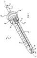
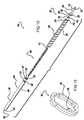
- FIG. 1is a perspective view of a multiple screw delivery apparatus constructed according to the present teachings
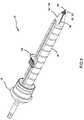
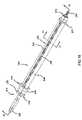
- FIG. 2is an exploded perspective view of the multiple screw delivery apparatus of FIG. 1 ;
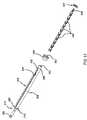
- FIG. 3is a perspective view of a screw-blade set shown in FIG. 2 ;
- FIG. 4is a cross-sectional view of the multiple screw delivery apparatus taken along line 4 - 4 in FIG. 1 ;
- FIG. 5is a perspective view of a multiple screw delivery apparatus according to the present teachings.
- FIG. 6is an exploded perspective view of the multiple screw delivery apparatus of FIG. 5 ;
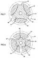
- FIG. 7is a cross-sectional schematic view of the multiple screw delivery apparatus of FIGS. 5 and 6 ;
- FIG. 8is another cross-sectional schematic view of the multiple screw delivery apparatus of FIGS. 5 and 6 ;
- FIG. 9is a perspective view of a multiple screw delivery apparatus according to the present teachings.
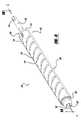
- FIG. 10is an exploded perspective view of the multiple screw delivery apparatus of FIG. 9 ;
- FIG. 11is a perspective view of a slide block shown in FIG. 10 ;
- FIG. 12is a perspective view of a stopper ring shown in FIG. 10 ;
- FIG. 13is an enlarged perspective view of a screw-blade set shown in FIG. 10 ;
- FIG. 14is a cross-sectional view of the screw delivery apparatus taken in the direction of arrow 14 - 14 in FIG. 9 ;
- FIG. 15is a cross-sectional view of the multiple screw delivery apparatus taken along line 15 - 15 in FIG. 14 ;
- FIG. 16is a perspective view of a multiple screw delivery apparatus according to the present teachings.
- FIG. 17is an exploded perspective view of the multiple screw delivery apparatus of FIG. 16 ;
- FIG. 18is a cross-sectional view of the multiple screw delivery apparatus taken along line 18 - 18 in FIG. 16 ;
- FIG. 19is a perspective view of a screw-blade set shown in FIGS. 16-18 ;
- FIG. 20is a perspective view of a stop ring shown in FIGS. 16-18 ;
- FIG. 21is a cross-sectional view of the multiple screw delivery apparatus taken along line 21 - 21 in FIG. 16 .
- a multiple screw delivery apparatus 10including a body 12 having a longitudinal axis indicated by line A-A.
- the body 12is sized to receive a clip 14 .
- a plurality of screw-blade sets 16are sized to fit within the clip 14 . Engagement of the clip 14 urges the screw-blade sets 16 to be positioned for use and subsequently ejected from the body 12 .
- the body 12includes a cap 18 and a tubular body 20 .
- the cap 18includes an inner body 22 mounted within a sleeve 24 .
- the inner body 22defines an opening 26 at one end sized to receive a portion of the tubular body 20 .
- a drive shaft 28extends out from an opposite end of the inner body 22 along axis A-A.
- the drive shaft 28has a hexagonally shaped end 30 adapted to be received by a tool.
- the sleeve 24is free to translate with respect to the inner body 22 along the axis A-A, and includes a flange 32 extending perpendicular to axis A-A along the circumference of the sleeve 24 to act as a grip for a user of the delivery apparatus 10 .
- the inner body 22includes a plurality of ball detents 34 mounted along an outer surface.
- the ball detents 34sit within detent slots 36 that extend into the opening 26 .
- the sleeve 24includes a projection 38 extending along the circumference of the inner surface of the sleeve 24 . When the projection 38 and the ball detents 34 are in alignment, the projection 38 urges the ball detents 34 within the detent slots 36 such that the ball detents 34 partially extend into the opening 26 where they may engage a portion of the tubular body 20 .
- the tubular body 20includes a dispensing end 40 and a cap end 42 .
- the tubular body 20further defines a bore 44 that extends from the dispensing end 40 to the cap end 42 along axis A-A.
- the bore 44is sized to receive the clip 14 .
- a longitudinal slot 45extends from the outer surface of the tubular body 20 into the bore 44 and runs from the insertion end 40 to near the dispensing end 42 along axis A-A.
- the longitudinal slot 45is sized to receive a portion of the clip 14 as will be described in greater detail below.
- the dispenser end 40is generally tapered with respect to the tubular body 20 and includes a pair of flexible tabs 46 that extend into the bore 44 .
- the flexible tabs 46are adapted to engage a portion of the screw-blade sets 16 .
- the dispensing end 40defines a hexagonal (keyed) opening 48 into the bore 44 .
- the cap end 42is sized to be received within the opening 26 of the cap 18 , and includes a reduced portion 50 having an outer diameter less than an inner diameter of the tubular body 20 whereby the reduced portion 50 fits within the opening 26 .
- a circumferential groove 52 formed around the tubular body 20 at the insertion end 42is sized to seat the ball detents 34 .
- the clip 14includes tubular halves 60 and a push block 62 .
- the tubular halves 60are adapted to be assembled together to form a sheath and are received within the bore 44 of the body 12 .
- Each tubular half 60has a generally half-circle cross section, and when joined encapsulate the push block 62 and the plurality of screw-blade sets 16 , as well as define a cavity 64 .
- the cavity 64may be generally hexagonal and extends along the axis A-A.
- a cavity slot 66extends into the cavity 64 from the surface of the joined tubular halves 60 and parallel to the axis A-A.
- the cavity slot 66is sized to receive a portion of the push block 62 .
- the tubular halves 60have a plurality of detents 68 formed in an inner surface defining the cavity 64 .
- Each detent 68has a sloped face 70 and a back wall 72 .
- the detents 68are sized to receive a portion of the push block 62 .
- the tube halves 60may be made from a liquid crystal polymer, such as VECTRA®, available from Ticona, Inc., of Germany. It is to be appreciated, however, that various other materials may be used.
- VECTRA®liquid crystal polymer
- the push block 62may include a hexagonally shaped block portion 74 sized to fit within the cavity 64 .
- a pair of posts 76extend out from the block portion 74 and end in a push pad 78 .
- the posts 76are sized to fit through the cavity slot 66 of the tubular halves 60 and the longitudinal slot 45 of the tubular body 20 .
- the push pad 78may include a rough grip surface designed to increase friction between the push pad 78 and the finger of a user of the dispensing apparatus 10 .
- the push pad 78may have various configurations and textures so long as it is operable by a user of the dispensing apparatus 10 .
- the block portion 74further includes a flexible tooth 80 extending therefrom.
- the flexible tooth 80is sized to fit within the plurality of detents 68 of the clip 14 and provides a ratcheting feature.
- each screw-blade set 16includes a blade 82 and a screw 84 .
- the blade 82includes a head 86 and a neck portion 88 extending axially therefrom.
- the head 86has a generally hexagonal shape matching the hexagonal shape of the cavity 64 of the clip 14 .
- the head 86may have various other shapes, including for example, oval, triangular, star, square, pentagonal, or octagonal shapes.
- variations in the shape of the head 86may require matching shapes in the cavity 64 , the push block 62 , and the opening 48 of the tubular body 20 .
- the head 86includes a circumferential recess 90 formed in its outer surface sized to receive the tabs 46 of the tubular body 20 . As best seen in FIG. 4 , the head 86 further defines a screw receptacle 92 at one end thereof. The screw receptacle is sized to receive the screw 84 from an adjacent screw-blade set 16 .
- the neck 88 of the blade 82is coupled to the screw 84 .
- the screw 84is press fitted to the neck 88 .
- the screw-blade set 16can be assembled in other ways, such as by welding, adhesive, or other bonding mechanism.
- the blade 82may be made from stainless steel and the screw 84 may be made from any of a variety of bio-compatible materials, such as commercially pure titanium, grade 2 or 4. Other metals that may be implanted are, but not limited to, stainless steel or cobalt chrome molybdenum. Other examples of bio-compatible materials that may be used are the implantable plastics PEEK or PET.
- the screw-blade sets 16may also be made from a variety of bio-resorbable materials.
- the screw-blade sets 16may be integrally formed with a joint between the screw 84 and blade 82 formed to shear at full insertion of the screw 84 .
- One such resorbable material of particular interestis marketed by Biomet, Inc. (Warsaw, Ind.) under the tradename LACTOSORB®.
- LACTOSORB®is an absorbable co-polymer synthesized from all-natural ingredients: 82% L-lactic acid and 18% glycolic acid, and is substantially amorphous (i.e., without crystallinity), meaning that its degradation is uniform, precluding the crystalline release associated with degrading copolymers that have been associated with late inflammatory reactions. Furthermore, the LACTOSORB® copolymer ratio permits the polymer to retain most of its strength for six to eight weeks. Such a time period is appropriate for healing, but not so long as to raise concerns about long-term stress shielding of bone. In addition to LACTOSORB®, other resorbable materials may be used such as PLA, PGA, and others including various polymers, ceramics, etc.
- the clip 14is loaded by inserting a plurality of the screw-blade sets 16 into the cavity 64 .
- the screws 84point towards the dispensing end 40 of the tubular body 20 .
- the screws 84fit within the screw receptacles 92 of adjacent screw-blade sets 16 to allow more screw-blade sets 16 to be loaded into the clip 14 .
- the push block 62is disposed at one end of the clip 14 and abuts the blade 82 of the screw-blade set 16 positioned most distal the dispensing end 40 of the tubular body 20 while the tooth 80 of the push block 62 seats within a detent 68 .
- the clip 14 and screw-blade sets 16may be sterilized and packaged separately from the body 12 .
- the loaded clip 14is inserted into the tubular body 20 such that the posts 76 of the push block 62 align with the longitudinal slot 45 formed in the tubular body 20 .
- the push pad 78is positioned adjacent the periphery of the body 12 .
- the cap 18is attached to the tubular body 20 by displacing the sleeve 24 so that the projections 38 no longer align with the ball detents 34 , thus allowing the insertion end 42 to be inserted into the opening 26 .
- the insertion end 42may be keyed to the opening 26 such that the cap 18 and the tubular body 20 are rotationally locked together.
- the ball detents 34are urged into the opening 26 and engage the circumferential groove 52 of the tubular body 20 , thereby securing the tubular body 20 to the cap 18 .
- Screws 84are made ready for insertion into a material by moving the push block 62 in the direction of the dispensing end 40 of the tubular body 20 . This forces the flexible tooth 80 to slide along ramped surface 70 of the detent 68 .
- the push block 62urges the plurality of screw-blade sets 16 along the axis A-A in the direction of the dispensing end 40 until the tooth 80 engages a succeeding detent 68 in the cavity 64 .
- a back wall 72prevents the push block 62 from moving toward the insertion end 42 , thus providing a ratchet effect.
- one of the screw-blade sets 16is in a use position wherein the tabs 46 have engaged the circumferential recess 90 of the screw-blade set 16 positioned adjacent the proximate end and the screw 84 extends from the dispensing end 40 . In this position the screw 84 is ready to be inserted into a material.
- the drive shaft 28may be rotated by a tool, which may be a hand-operated tool or powered driver having a connector adapted to receive the hexagonally shaped end 30 .
- the powered drivermay include multiple forward and reverse speeds to facilitate insertion and removal of screws 84 .
- the toolmay be fingertip actuated and held in a pencil-grip style, such as Power Driver, available from Walter Lorenz Surgical, Inc. of Jacksonville, Fla.
- the screwdriveris powered by a 6-volt lithium-ion battery pack, which is sold sterile.
- the drive shaft 28may be rotated by various other means, for example by the hand of the user, or another tool such as a conventional screwdriver or pliers.
- the screw 84disengages from the blade 82 under sufficient rotational resistance, for example, at full insertion of the screw 84 in a material, at which time the coupling between the screw 84 and blade 82 is broken.
- a usermay also rock the multiple screw delivery apparatus 10 after the screw 84 is seated within a material in order to decouple the screw 84 from the blade 82 .
- the tabs 46retain the blade 82 until such time as the push block 62 is again urged in the direction of the insertion end 42 , wherein the next screw-blade set 16 ejects the blade 82 and is moved to the use position.
- a multiple screw delivery apparatusis generally indicated by reference numeral 10 ′.
- the multiple screw delivery apparatus 10 ′is generally similar to the multiple screw apparatus shown in FIGS. 1-4 , and includes a clip 14 ′, 14 ′′, a screw set 16 ′ (including screws 84 ′ or screws 84 ′′), and a dispenser end 40 ′.
- the screw 84 ′ and the screw 84 ′′differ in the configuration of the head portion, and similarly, the clip 14 ′ and 14 ′′ differ in their internal geometry to accommodate respective screws 84 ′, 84 ′′.
- the screw set 16 ′includes screws 84 ′, 84 ′′ nested within another screw 84 ′, 84 ′′, respectively, in series. Accordingly, the screw set 16 ′ may not require a blade 82 (as discussed previously and shown in FIG. 3 ) between succeeding screws 84 ′, 84 ′′. Each screw 84 ′, 84 ′′ may directly engage a succeeding screw 84 ′, 84 ′′, respectively, as the push pad 78 is urged through the clip 14 ′, 14 ′′, toward the dispenser end 40 ′.
- the clip 14 ′, 14 ′′ and the dispensing end 40 ′, 40 ′′include an internal geometry suited to a particular screw 84 ′, 84 ′′.
- the cavity 64 of clip 14 ′, 14 ′′is defined by rails 94 , 94 ′ spaced equidistantly and formed axially along an inner diameter surface of the clip 14 ′, 14 ′′.
- the rails 94 , 94 ′are received in grooves 97 , 97 ′ formed in a head portion of each of the screws 84 ′, 84 ′′, respectively.
- the rails 94 , 94 ′ and grooves 97 , 97 ′prevent the screws 84 ′, 84 ′′ from rotating or misaligning while within the clip 14 ′, 14 ′′.
- the screw 84 ′is a three-lobed screw, whereby the head portion 96 of the screw 84 ′ includes three equidistantly-spaced lobes 96 .
- the grooves 97 between the lobes 96align with the rails 94 of the clip 14 ′.
- the lobes 96are aligned with slits 98 in the dispensing end 40 ′.
- the screw 84 ′′is a six-lobed screw, wherein the head portion includes six lobes 96 ′.
- the clip 14 ′′includes rails 94 ′ and slots 95 ′ accommodating the grooves 97 ′ and lobes 96 ′ of the screw 84 ′′, respectively.
- the lobes 96 ′are alternately aligned with channels 91 ′ and slits 98 .
- various other screw designsmay be employed with the present invention by varying the arrangement of rails 94 , 94 ′, slots 95 , 95 ′, grooves 97 , 97 ′ and slits 98 .
- the dispensing end 40 ′, 40 ′′is generally tapered with respect to the tubular body 20 , includes a geometrical tip (or keyed) opening 92 , 92 ′, and three slits 98 .
- the opening 92 , 92 ′allows the passage of screws 84 ′, 84 ′′ as they are passed from the clip 14 ′, 14 ′′ and generally includes lobes 99 , 99 ′ operable to position the screws 84 ′, 84 ′′ for use.
- the lobes 99 of the opening 92have a generally convex surface 91 for alignment with the grooves 97 of the screw 84 ′.
- the lobes 99 ′ of the opening 92 ′include a channel 91 ′ for alignment with the lobes 96 ′.
- the apparatus 10 ′through the cooperating geometries of the screws 84 ′, 84 ′′, dispensing end 40 ′, 40 ′′ and clip 14 ′, 14 ′′, maintain alignment of the screws 84 ′, 84 ′′ within the body 20 and fix the screws 84 ′, 84 ′′ for rotation with the apparatus 10 ′.
- the slits 98extend axially from the tip opening 92 along the tubular body 20 and allow the dispensing end 40 ′, 40 ′′ to deflect away from the screws 84 ′, 84 ′′ as the screws are dispensed from the multiple screw delivery apparatus 10 ′, whereby the screws 84 ′, 84 ′′ are quickly released from the dispensing end 40 ′, 40 ′′ when enough force is applied thereto.
- the delivery apparatus 100includes a body 102 with a longitudinal axis indicated by line B-B.
- the body 102is sized to receive a clip 104 .
- a plurality of screw-blade sets 106are sized to fit within the clip 104 .
- a stopper ring 107is mounted to the clip 104 . Rotation of the clip 104 relative to the body 102 urges the screw-blade sets 106 to be positioned for use and subsequently ejected from the clip 104 .
- the body 102includes a tubular portion 108 with a cap 110 attached thereto.
- the tubular portion 108includes a dispensing end 112 and a cap end 114 .
- the tubular portion 108further defines a bore 116 that extends from the dispensing end 112 to the cap end 114 along an axis B-B.
- the bore 116is sized to receive the clip 104 .
- a spiral groove 118 formed in the bore 116runs from the cap end 114 to adjacent the dispensing end 112 along the axis B-B.
- the cutouts 120extend from the outside of the tubular portion 108 into the bore 114 and form the groove 118 .
- the spiral groove 118receives a portion of the clip 104 , as will be described below.
- the cap 110includes circular base 121 with a lug 122 extending from an end thereof.
- the lug 122includes notches 124 that engage the clip 104 and rotationally fix it relative to the cap 110 .
- a drive shaft 126extends out from an opposite side of the cap 110 along the axis B-B.
- the drive shaft 126may include a hexagonally shaped end 128 adapted to be received within a tool such as those described above.
- the clip 104includes a sheath 130 and a slide block 132 .
- the sheath 130has a cap end 134 and a dispensing end 136 and is sized to fit within the bore 116 of the tubular portion 108 .
- the sheath 130defines a cavity 138 that extends along axis B-B from the cap end 134 to the dispensing end 136 .
- a longitudinal slot 140extends from the surface of the sheath 130 into the cavity 138 and from the cap end 134 parallel to the axis B-B and adjacent the dispensing end 136 .
- the cavity 138includes rails 142 that extend along the length of the cavity 138 .
- the rails 142are sized to engage the screw-blade sets 106 and ride within the notches 124 of the cap 110 .
- the longitudinal slot 140is sized to receive a portion of the stopper ring 107 .
- the clip 104may be formed from a liquid crystal polymer, for example VECTRA® as described above. Another material may be stainless steel. However, various other materials may be employed.
- the slide block 132includes a block body 146 having cutouts 148 sized to receive the rails 142 of the sheath 130 .
- a post 150extends out from the block body 146 and is received within the longitudinal slot 140 ( FIG. 10 ) and the spiral groove 118 ( FIG. 9 ).
- the slide block 132engages the screw-blade sets 106 and urges them to a use position and subsequently ejects them from the dispensing apparatus 100 .
- the stopper ring 107includes a ring portion 152 received on the dispensing end 136 of the sheath 130 .
- a stopper 154extends radially inward from the inner diameter surface of the ring portion 152 and is received within the longitudinal slot 140 in the clip 104 . The stopper 154 engages the screw-blade set 106 positioned most proximate to the dispensing end 136 .
- the screw-blade set 106includes a blade 156 and a screw 158 coupled by a neck portion 160 , which may include a reduced cross-sectional area.
- the blade 156has grooves 162 formed therein and adapted to receive the rails 142 .
- a circumferential recess 164 formed in the outer surface of the blade 156receives the stopper 154 ( FIG. 12 ).
- the blade 156includes a screw receptacle 166 for receiving the screw 158 from a separate, adjacent screw-blade set 106 .
- the blade 156 , the screw 158 , and the neck portion 260may be formed unitarily from a bio-resorbable material, for example LACTOSORB® as described above.
- the blade 156 and the screw 158may be formed from a variety of bio-compatible materials. Further, the blade 156 and screw 158 may be joined in any other manner, such as those discussed above.
- the clip 104is loaded by inserting a plurality of the screw-blade sets 106 into the cavity 138 .
- the rails 142slide within the grooves 162 of the blade 156 ( FIG. 15 ).
- the screws 158are received within the screw receptacles 166 of adjacent screw-blade sets 106 to allow more screw-blade sets 106 to be loaded into the clip 104 .
- the push block 132When fully loaded, the push block 132 is disposed at the cap end 114 of the sheath 130 , post 150 extends through the longitudinal slot 140 of the sheath 130 , and the block body 146 abuts the blade 156 of the screw-blade set 106 most proximate to the dispensing end 136 .
- the loaded clip 104is inserted into the tubular portion 108 such that the post 150 of the push block 132 extends into the spiral groove 118 and the loaded screws 158 point towards the dispensing end 112 of the tubular portion 108 .
- the cap 110is then attached to the loaded clip 104 such that the notches 124 receive the rails 142 to rotationally lock the clip 104 to the cap 110 .
- the stopper ring 107is fitted around the sheath 130 such that the stopper 154 extends through the longitudinal slot 140 into the cavity 138 .
- the screws 158are made ready for insertion into a material by rotating the tubular portion 108 relative to the cap 110 and the clip 104 , which, in turn, causes the post 150 and the slide block 132 to move along the axis B-B because the post 150 is constrained by the spiral groove 118 and the longitudinal slot 140 .
- the slide block 132urges the loaded screw-blade sets 106 along the axis B-B in the direction of the dispensing end 136 of the sheath 130 until the stopper 154 engages the circumferential recess 164 formed in the blade 156 of the screw-blade set 106 positioned proximate the dispensing end 136 . In this position, the screw 158 extends from the dispensing end 136 and is ready to be inserted into a material.
- Rotation of the drive shaft 126rotates the sheath 130 , which through rails 142 rotates the screw-blade sets 106 .
- the screw 158disengages from the blade 156 under sufficient rotational resistance at which time the neck portion 160 may be sheared from an increased shear stress due to its reduced cross sectional area.
- the stopper 154retains the remaining blade 156 until such time as the tubular portion 108 is again rotated relative to the cap 110 and the slide block 132 urges a new screw-blade set 106 into an extended or use position and ejects the spent blade 156 .
- a multiple screw delivery apparatusis indicated generally by reference numeral 200 and includes a body 202 adapted to receive a plurality of screw-blade sets 206 , each including a blade 256 and a screw 258 connected by a neck portion 260 .
- a stopper ring 207is mounted to the body 202 and is positioned to releasably retain the screw-blade set 206 in position for use.
- a pusher 218is mounted to the clip 204 at an end opposite the stopper ring 207 and is slidably moveable along the body 202 toward the stopper ring 207 to urge one of the screw-blade sets 206 into position for use and to subsequently eject used blades 256 from the body 202 .
- the body 202includes a tubular portion 208 , which includes a dispensing end 212 and a cap end 214 .
- a cap 210covers the cap end 214 of the tubular portion 208 , and may be integrally formed with the body 202 or fixedly attached.
- the tubular portion 208defines a cavity 216 that may extend from the dispensing end 212 to the cap end 214 , and which is sized to receive one or more screw-blade sets 206 .
- a groove 204 formed in the tubular portion 208extends axially from the cap end 214 to adjacent the dispensing end 212 , into the cavity 216 , and slidably receives a portion of the pusher 218 .
- the cap 210includes a circular base 220 rotationally fixed to the body 202 .
- a drive shaft 226extends from the cap 210 in a direction opposite from the dispensing end 212 .
- the drive shaft 226may include a hexagonally-shaped end 228 adapted to be received within a tool such as those described above.
- the pusher 218includes a cylindrical body 230 having a slot 232 axially formed through the body and a block 234 extending radially inward along an inner diameter surface of the body 230 diametrically opposite the slot 232 .
- the push block 234is shaped to abut and slide the screw-blade sets 206 within the body 202 , sequentially advancing one of the screw-blade sets 206 to the use position. As shown, the push block 234 extends through the slot 204 to engage an end portion of a blade 256 of the screw-blade set 206 most distant to the dispensing end 212 .
- the tubular portion 208 of the body 202includes rails 242 that extending along the length of the inner diameter of the tubular portion 208 and adapted to engage the screw-blade sets 206 .
- the blade 256 and the screw 258include grooves 262 formed therein to receive the rails 242 .
- a circumferential recess 264is formed in the outer surface of the blade 256 and receives the stopper ring 207 , depending on the position of the blade 256 in the series of screw-blade sets 206 .
- the push block 234abuts the blade 256 most distant from the dispensing end 212 and sequentially urges the series of screw-blade sets 206 to a use position, and subsequently ejects used blades 256 from the apparatus 200 .
- the blade 256 , the screw 258 and the neck portion 260may be formed unitarily from a bio-resorbable material, for example, LACTOSORB®, as described above.
- the blade 256 and the screw 258may be formed from a variety of bio-compatible materials. Further, the blade 256 and the screw 258 may be joined in any other manner, such as those discussed above.
- the stopper ring 207includes a ring portion 252 having a slot 251 formed through the body and a stopper 254 disposed radially inward from an inner diameter surface of the body 252 approximately diametrically opposed to the slot 251 .
- Flats 257are formed along an inner diameter surface of the ring portion 252 between the slot 251 and stopper 254 .
- the slot 251is flanked by hooks 253 , which secure the stopper ring 207 to the body 202 through engagement with hook openings (not shown) through a surface of the body 202 generally opposite an aperture 205 adapted to receive the stopper 254 .
- the stopper ring 207is fitted around the tubular portion 208 of the body 202 , the stopper 254 extends through the aperture 205 to selectively engage a screw-blade set 206 , and the flats 257 seat in slots 209 formed on the body 202 between the aperture 205 and hook openings (not shown).
- the pusher 218is placed on the body 202 with the push block 234 extending into the cavity 216 through the slot 204 .
- the body 202is loaded by inserting a plurality of the screw-blade sets 206 into the cavity 216 of the tubular portion 208 through the dispensing end 212 .
- the rails 242slide within the grooves 262 of the screw-blade sets 206 .
- the screws 258are received in the screw receptacles 266 of adjacent screw-blade sets 206 to allow a greater number of screw-blade sets 206 to be loaded into the body 202 .
- the push block 234 of the pusher 218abuts the blade 256 of the screw-blade set 206 most distant from the dispensing end 212 .
- the stopper ring 207is fitted around the body 202 with the stopper 254 extending through aperture 205 and hooks 253 received by openings 209 to retain the series of screw-blade sets 206 within the tubular portion 208 .
- the screws 258are ready for insertion into a material by rotating the tubular portion 208 through rotation of the drive shaft 226 rotationally fixed thereto via the cap 210 .
- the pusher 218urges the loaded screw-blade sets 206 toward a dispensing end 212 until the stopper 254 of the stop ring 207 engages the circumferential recess 264 formed in the blade 256 of the screw-blade set 206 positioned proximate the dispensing end 212 .
- the screw 258 extending from the dispensing end 212is ready to be inserted into a material by rotation of the body 202 , such as by rotation of the drive shaft 226 .
- the screw 258may disengage from the blade 256 under sufficient rotational resistance, at which time the neck portion 260 may be sheared from an increased shear stress due to its reduced cross-sectional area.
- the stopper 254retains the remaining blade 256 until such time as the pusher 218 is again urged toward the dispensing end 212 to locate a new screw-blade set 206 in the use position and eject the spent blade 256 .
Landscapes
- Health & Medical Sciences (AREA)
- Orthopedic Medicine & Surgery (AREA)
- Life Sciences & Earth Sciences (AREA)
- Surgery (AREA)
- Medical Informatics (AREA)
- Engineering & Computer Science (AREA)
- Biomedical Technology (AREA)
- Heart & Thoracic Surgery (AREA)
- Nuclear Medicine, Radiotherapy & Molecular Imaging (AREA)
- Molecular Biology (AREA)
- Animal Behavior & Ethology (AREA)
- General Health & Medical Sciences (AREA)
- Public Health (AREA)
- Veterinary Medicine (AREA)
- Neurology (AREA)
- Surgical Instruments (AREA)
Abstract
Description
Claims (20)
Priority Applications (1)
| Application Number | Priority Date | Filing Date | Title |
|---|---|---|---|
| US10/833,260US7461574B2 (en) | 2003-04-28 | 2004-04-27 | Multiple screw delivery apparatus |
Applications Claiming Priority (2)
| Application Number | Priority Date | Filing Date | Title |
|---|---|---|---|
| US46639403P | 2003-04-28 | 2003-04-28 | |
| US10/833,260US7461574B2 (en) | 2003-04-28 | 2004-04-27 | Multiple screw delivery apparatus |
Publications (2)
| Publication Number | Publication Date |
|---|---|
| US20040243139A1 US20040243139A1 (en) | 2004-12-02 |
| US7461574B2true US7461574B2 (en) | 2008-12-09 |
Family
ID=33511580
Family Applications (1)
| Application Number | Title | Priority Date | Filing Date |
|---|---|---|---|
| US10/833,260Active2026-02-01US7461574B2 (en) | 2003-04-28 | 2004-04-27 | Multiple screw delivery apparatus |
Country Status (2)
| Country | Link |
|---|---|
| US (1) | US7461574B2 (en) |
| JP (1) | JP4018665B2 (en) |
Cited By (31)
| Publication number | Priority date | Publication date | Assignee | Title |
|---|---|---|---|---|
| US20080281353A1 (en)* | 2007-05-10 | 2008-11-13 | Ernest Aranyi | Powered tacker instrument |
| US20090048613A1 (en)* | 2007-08-17 | 2009-02-19 | Wilson-Cook Medical Inc. | Visceral staples for purse-string closure of perforations |
| US20100121386A1 (en)* | 2008-11-05 | 2010-05-13 | Warsaw Orthopedic, Inc. | Progressive Reduction Instrument for Reduction of a Vertebral Rod and Method of Use |
| US20100130989A1 (en)* | 2008-11-26 | 2010-05-27 | Smith & Nephew, Inc. | Tissue Repair Device |
| US20110087240A1 (en)* | 2004-04-27 | 2011-04-14 | Tyco Healthcare Group Lp | Absorbable fastener for hernia mesh fixation |
| US20110130767A1 (en)* | 2009-12-01 | 2011-06-02 | Philip Watt | Screw delivery system |
| US20120057949A1 (en)* | 2010-09-03 | 2012-03-08 | Canizares Jr Eduardo Antonio | Modified fastener and insertion tool |
| US20120138656A1 (en)* | 2010-12-06 | 2012-06-07 | Xu Jun-Xiu | Nail gun adaptable to nails of different length |
| US8556904B2 (en) | 2011-05-05 | 2013-10-15 | Warsaw Orthopedic, Inc. | Anchors extender assemblies and methods for using |
| WO2015127006A1 (en)* | 2014-02-21 | 2015-08-27 | Dominion Resources, Inc. | Fastener holder |
| WO2017156121A1 (en)* | 2016-03-08 | 2017-09-14 | K2M, Inc. | Fixation devices, fixation systems, and methods of using the same |
| US9827024B2 (en)* | 2012-09-28 | 2017-11-28 | DePuy Synthes Products, Inc. | Devices and methods for breaking and retaining surgical reduction tabs |
| US9833231B2 (en) | 1999-12-02 | 2017-12-05 | Smith & Nephew, Inc. | Apparatus for tissue repair |
| US9911019B2 (en) | 2014-11-25 | 2018-03-06 | DePuy Synthes Products, Inc. | Medical device identification system |
| US9918755B2 (en) | 2015-06-29 | 2018-03-20 | DePuy Synthes Products, Inc. | Implant dispenser |
| US10617409B2 (en) | 2016-10-21 | 2020-04-14 | Covidien Lp | Surgical end effectors |
| US10743859B2 (en) | 2016-10-21 | 2020-08-18 | Covidien Lp | Surgical end effectors |
| US10786250B2 (en) | 2013-06-28 | 2020-09-29 | Covidien Lp | Surgical instrument including rotating end effector and rotation-limiting structure |
| US10888309B2 (en) | 2017-01-31 | 2021-01-12 | Covidien Lp | Surgical fastener devices with geometric tubes |
| US11065745B2 (en) | 2015-09-25 | 2021-07-20 | Zimmer Biomet CMF and Thoracic, LLC | Fastener cartridge |
| US11116500B2 (en) | 2018-06-28 | 2021-09-14 | Covidien Lp | Surgical fastener applying device, kits and methods for endoscopic procedures |
| US11154337B2 (en) | 2019-02-26 | 2021-10-26 | Medos Iniernational Sarl | Spinal screw handling |
| US11197675B2 (en) | 2019-12-19 | 2021-12-14 | Covidien Lp | Positioning guide for surgical instruments and surgical instrument systems |
| USD944984S1 (en) | 2019-12-19 | 2022-03-01 | Covidien Lp | Tubular positioning guide |
| USD944985S1 (en) | 2019-12-19 | 2022-03-01 | Covidien Lp | Positioning guide cuff |
| US11298126B2 (en) | 2018-05-02 | 2022-04-12 | Covidien Lp | Shipping wedge for end effector installation onto surgical devices |
| US11298123B2 (en) | 2016-10-21 | 2022-04-12 | Covidien Lp | Surgical end effectors |
| USD951050S1 (en) | 2020-10-14 | 2022-05-10 | Simpson Strong-Tie Company Inc. | Fastener driving tool adapter |
| USD951741S1 (en) | 2020-10-14 | 2022-05-17 | Simpson Strong-Tie Company Inc. | Screw driving tool |
| US11523817B2 (en) | 2019-06-27 | 2022-12-13 | Covidien Lp | Endoluminal pursestring device |
| US12171477B1 (en) | 2024-02-10 | 2024-12-24 | Peter Eric Pierman | Surgical screw caddy |
Families Citing this family (128)
| Publication number | Priority date | Publication date | Assignee | Title |
|---|---|---|---|---|
| AU2002348033B2 (en) | 2001-10-23 | 2008-05-29 | Covidien Lp | Surgical fasteners |
| ES2279156T3 (en) | 2002-06-11 | 2007-08-16 | Tyco Healthcare Group Lp | MALE TIGHTS FOR HERNIAS. |
| US7887539B2 (en) | 2003-01-24 | 2011-02-15 | Depuy Spine, Inc. | Spinal rod approximators |
| US7670362B2 (en) | 2003-06-13 | 2010-03-02 | Tyco Healthcare Group Lp | Multiple member interconnect for surgical instrument and absorbable screw fastener |
| US8926637B2 (en) | 2003-06-13 | 2015-01-06 | Covidien Lp | Multiple member interconnect for surgical instrument and absorbable screw fastener |
| US7967826B2 (en) | 2003-10-21 | 2011-06-28 | Theken Spine, Llc | Connector transfer tool for internal structure stabilization systems |
| US7588575B2 (en) | 2003-10-21 | 2009-09-15 | Innovative Spinal Technologies | Extension for use with stabilization systems for internal structures |
| US7766920B2 (en)* | 2003-11-26 | 2010-08-03 | Synthes Usa, Llc | Cannulated fastener system |
| US7179261B2 (en)* | 2003-12-16 | 2007-02-20 | Depuy Spine, Inc. | Percutaneous access devices and bone anchor assemblies |
| US11419642B2 (en) | 2003-12-16 | 2022-08-23 | Medos International Sarl | Percutaneous access devices and bone anchor assemblies |
| US7678137B2 (en) | 2004-01-13 | 2010-03-16 | Life Spine, Inc. | Pedicle screw constructs for spine fixation systems |
| US7608092B1 (en) | 2004-02-20 | 2009-10-27 | Biomet Sports Medicince, LLC | Method and apparatus for performing meniscus repair |
| US8021398B2 (en) | 2004-06-09 | 2011-09-20 | Life Spine, Inc. | Spinal fixation system |
| US7744635B2 (en)* | 2004-06-09 | 2010-06-29 | Spinal Generations, Llc | Spinal fixation system |
| US7938848B2 (en) | 2004-06-09 | 2011-05-10 | Life Spine, Inc. | Spinal fixation system |
| US8118836B2 (en) | 2004-11-05 | 2012-02-21 | Biomet Sports Medicine, Llc | Method and apparatus for coupling soft tissue to a bone |
| US8128658B2 (en) | 2004-11-05 | 2012-03-06 | Biomet Sports Medicine, Llc | Method and apparatus for coupling soft tissue to bone |
| US9801708B2 (en) | 2004-11-05 | 2017-10-31 | Biomet Sports Medicine, Llc | Method and apparatus for coupling soft tissue to a bone |
| US8088130B2 (en) | 2006-02-03 | 2012-01-03 | Biomet Sports Medicine, Llc | Method and apparatus for coupling soft tissue to a bone |
| US7905904B2 (en) | 2006-02-03 | 2011-03-15 | Biomet Sports Medicine, Llc | Soft tissue repair device and associated methods |
| US8137382B2 (en) | 2004-11-05 | 2012-03-20 | Biomet Sports Medicine, Llc | Method and apparatus for coupling anatomical features |
| US7749250B2 (en) | 2006-02-03 | 2010-07-06 | Biomet Sports Medicine, Llc | Soft tissue repair assembly and associated method |
| US7658751B2 (en) | 2006-09-29 | 2010-02-09 | Biomet Sports Medicine, Llc | Method for implanting soft tissue |
| US8298262B2 (en) | 2006-02-03 | 2012-10-30 | Biomet Sports Medicine, Llc | Method for tissue fixation |
| US9017381B2 (en) | 2007-04-10 | 2015-04-28 | Biomet Sports Medicine, Llc | Adjustable knotless loops |
| US20060189993A1 (en) | 2004-11-09 | 2006-08-24 | Arthrotek, Inc. | Soft tissue conduit device |
| US7857830B2 (en) | 2006-02-03 | 2010-12-28 | Biomet Sports Medicine, Llc | Soft tissue repair and conduit device |
| US8840645B2 (en) | 2004-11-05 | 2014-09-23 | Biomet Sports Medicine, Llc | Method and apparatus for coupling soft tissue to a bone |
| US8303604B2 (en) | 2004-11-05 | 2012-11-06 | Biomet Sports Medicine, Llc | Soft tissue repair device and method |
| US7909851B2 (en) | 2006-02-03 | 2011-03-22 | Biomet Sports Medicine, Llc | Soft tissue repair device and associated methods |
| US7905903B2 (en) | 2006-02-03 | 2011-03-15 | Biomet Sports Medicine, Llc | Method for tissue fixation |
| US8361113B2 (en) | 2006-02-03 | 2013-01-29 | Biomet Sports Medicine, Llc | Method and apparatus for coupling soft tissue to a bone |
| US7608098B1 (en) | 2004-11-09 | 2009-10-27 | Biomet Sports Medicine, Llc | Bone fixation device |
| US7914539B2 (en) | 2004-11-09 | 2011-03-29 | Biomet Sports Medicine, Llc | Tissue fixation device |
| US8034090B2 (en) | 2004-11-09 | 2011-10-11 | Biomet Sports Medicine, Llc | Tissue fixation device |
| US8998949B2 (en) | 2004-11-09 | 2015-04-07 | Biomet Sports Medicine, Llc | Soft tissue conduit device |
| US7951172B2 (en) | 2005-03-04 | 2011-05-31 | Depuy Spine Sarl | Constrained motion bone screw assembly |
| US7951175B2 (en) | 2005-03-04 | 2011-05-31 | Depuy Spine, Inc. | Instruments and methods for manipulating a vertebra |
| US20060241593A1 (en)* | 2005-04-08 | 2006-10-26 | Sdgi Holdings, Inc. | Multi-piece vertebral attachment device |
| US7947047B2 (en)* | 2005-06-20 | 2011-05-24 | Ams Research Corporation | Medical screwdrivers and methods |
| US7717921B2 (en)* | 2005-10-19 | 2010-05-18 | Warsaw Orthopedic, Inc. | Instruments and methods for delivering multiple implants in a surgical procedure |
| EP1971282A2 (en) | 2006-01-10 | 2008-09-24 | Life Spine, Inc. | Pedicle screw constructs and spinal rod attachment assemblies |
| US9468433B2 (en) | 2006-02-03 | 2016-10-18 | Biomet Sports Medicine, Llc | Method and apparatus for forming a self-locking adjustable loop |
| US8574235B2 (en) | 2006-02-03 | 2013-11-05 | Biomet Sports Medicine, Llc | Method for trochanteric reattachment |
| US9078644B2 (en) | 2006-09-29 | 2015-07-14 | Biomet Sports Medicine, Llc | Fracture fixation device |
| US8968364B2 (en) | 2006-02-03 | 2015-03-03 | Biomet Sports Medicine, Llc | Method and apparatus for fixation of an ACL graft |
| US9538998B2 (en) | 2006-02-03 | 2017-01-10 | Biomet Sports Medicine, Llc | Method and apparatus for fracture fixation |
| US11259792B2 (en) | 2006-02-03 | 2022-03-01 | Biomet Sports Medicine, Llc | Method and apparatus for coupling anatomical features |
| US8652172B2 (en) | 2006-02-03 | 2014-02-18 | Biomet Sports Medicine, Llc | Flexible anchors for tissue fixation |
| US9271713B2 (en) | 2006-02-03 | 2016-03-01 | Biomet Sports Medicine, Llc | Method and apparatus for tensioning a suture |
| US8652171B2 (en) | 2006-02-03 | 2014-02-18 | Biomet Sports Medicine, Llc | Method and apparatus for soft tissue fixation |
| US10517587B2 (en) | 2006-02-03 | 2019-12-31 | Biomet Sports Medicine, Llc | Method and apparatus for forming a self-locking adjustable loop |
| US8801783B2 (en) | 2006-09-29 | 2014-08-12 | Biomet Sports Medicine, Llc | Prosthetic ligament system for knee joint |
| US9149267B2 (en) | 2006-02-03 | 2015-10-06 | Biomet Sports Medicine, Llc | Method and apparatus for coupling soft tissue to a bone |
| US8597327B2 (en) | 2006-02-03 | 2013-12-03 | Biomet Manufacturing, Llc | Method and apparatus for sternal closure |
| US8562647B2 (en) | 2006-09-29 | 2013-10-22 | Biomet Sports Medicine, Llc | Method and apparatus for securing soft tissue to bone |
| US8771352B2 (en) | 2011-05-17 | 2014-07-08 | Biomet Sports Medicine, Llc | Method and apparatus for tibial fixation of an ACL graft |
| US7959650B2 (en) | 2006-09-29 | 2011-06-14 | Biomet Sports Medicine, Llc | Adjustable knotless loops |
| US8562645B2 (en) | 2006-09-29 | 2013-10-22 | Biomet Sports Medicine, Llc | Method and apparatus for forming a self-locking adjustable loop |
| US8506597B2 (en) | 2011-10-25 | 2013-08-13 | Biomet Sports Medicine, Llc | Method and apparatus for interosseous membrane reconstruction |
| US8251998B2 (en) | 2006-08-16 | 2012-08-28 | Biomet Sports Medicine, Llc | Chondral defect repair |
| US11311287B2 (en) | 2006-02-03 | 2022-04-26 | Biomet Sports Medicine, Llc | Method for tissue fixation |
| US7722623B2 (en)* | 2006-05-12 | 2010-05-25 | Warsaw Orthopedic, Inc. | Instruments and methods for delivering multiple implants |
| US7918857B2 (en) | 2006-09-26 | 2011-04-05 | Depuy Spine, Inc. | Minimally invasive bone anchor extensions |
| US11259794B2 (en) | 2006-09-29 | 2022-03-01 | Biomet Sports Medicine, Llc | Method for implanting soft tissue |
| US8500818B2 (en) | 2006-09-29 | 2013-08-06 | Biomet Manufacturing, Llc | Knee prosthesis assembly with ligament link |
| US9918826B2 (en) | 2006-09-29 | 2018-03-20 | Biomet Sports Medicine, Llc | Scaffold for spring ligament repair |
| US8672969B2 (en) | 2006-09-29 | 2014-03-18 | Biomet Sports Medicine, Llc | Fracture fixation device |
| US7967828B2 (en)* | 2006-12-07 | 2011-06-28 | Warsaw Orthopedic, Inc. | Gravity feed implant dispenser |
| US20080172062A1 (en)* | 2007-01-12 | 2008-07-17 | Depuy Spine, Inc. | Bone anchor manipulation device |
| US8105328B2 (en)* | 2007-02-01 | 2012-01-31 | Warsaw Orthopedic, Inc. | Multiple implant dispensing driver |
| US8845652B2 (en)* | 2007-02-27 | 2014-09-30 | Warsaw Orthopedic, Inc. | Surgical driver |
| US20080275459A1 (en)* | 2007-05-02 | 2008-11-06 | Charles Anthony Dickinson | Surgical instrument attachment mechanism |
| DE102007045757A1 (en)* | 2007-09-25 | 2009-04-09 | Ejot Gmbh & Co. Kg | Apparatus for aligning fasteners with radially symmetric polygonal heads in a feeder |
| US8414588B2 (en) | 2007-10-04 | 2013-04-09 | Depuy Spine, Inc. | Methods and devices for minimally invasive spinal connection element delivery |
| US8709015B2 (en) | 2008-03-10 | 2014-04-29 | DePuy Synthes Products, LLC | Bilateral vertebral body derotation system |
| US8608746B2 (en) | 2008-03-10 | 2013-12-17 | DePuy Synthes Products, LLC | Derotation instrument with reduction functionality |
| US10973556B2 (en) | 2008-06-17 | 2021-04-13 | DePuy Synthes Products, Inc. | Adjustable implant assembly |
| US12419632B2 (en) | 2008-08-22 | 2025-09-23 | Biomet Sports Medicine, Llc | Method and apparatus for coupling anatomical features |
| US12245759B2 (en) | 2008-08-22 | 2025-03-11 | Biomet Sports Medicine, Llc | Method and apparatus for coupling soft tissue to bone |
| US8262669B2 (en)* | 2009-01-14 | 2012-09-11 | Walker Douglas W | Method for using an automatic feed medical screwdriver |
| US20100198271A1 (en)* | 2009-02-02 | 2010-08-05 | Vincent Leone | Screw Sheath for Minimally Invasive Spinal Surgery and Method Relating Thereto |
| US8343227B2 (en) | 2009-05-28 | 2013-01-01 | Biomet Manufacturing Corp. | Knee prosthesis assembly with ligament link |
| US12096928B2 (en) | 2009-05-29 | 2024-09-24 | Biomet Sports Medicine, Llc | Method and apparatus for coupling soft tissue to a bone |
| US8377074B2 (en)* | 2009-06-25 | 2013-02-19 | Saddy R. Garcia | Surgical screw cartridge system for rapidly and accurately loading surgical screws onto a driver |
| JP5671620B2 (en)* | 2010-09-30 | 2015-02-18 | ストライカー トラウマ ゲーエムベーハー | System for inserting pins into screws |
| US12329373B2 (en) | 2011-05-02 | 2025-06-17 | Biomet Sports Medicine, Llc | Method and apparatus for soft tissue fixation |
| US20140127645A1 (en)* | 2011-06-30 | 2014-05-08 | Precise Implant Systems E.S. Ltd. | Medical and dental implant package |
| US9005249B2 (en) | 2011-07-11 | 2015-04-14 | Life Spine, Inc. | Spinal rod connector assembly |
| CA2849887A1 (en)* | 2011-09-26 | 2013-04-04 | Artack Medical (2013) Ltd. | Surgical fastening device and method |
| US9357991B2 (en) | 2011-11-03 | 2016-06-07 | Biomet Sports Medicine, Llc | Method and apparatus for stitching tendons |
| US9370350B2 (en) | 2011-11-10 | 2016-06-21 | Biomet Sports Medicine, Llc | Apparatus for coupling soft tissue to a bone |
| US9381013B2 (en) | 2011-11-10 | 2016-07-05 | Biomet Sports Medicine, Llc | Method for coupling soft tissue to a bone |
| US9314241B2 (en) | 2011-11-10 | 2016-04-19 | Biomet Sports Medicine, Llc | Apparatus for coupling soft tissue to a bone |
| US9259217B2 (en) | 2012-01-03 | 2016-02-16 | Biomet Manufacturing, Llc | Suture Button |
| JP5922262B2 (en) | 2012-02-29 | 2016-05-24 | ストライカー トラウマ ゲーエムベーハー | System for handling augmented implants |
| US9421037B2 (en)* | 2012-05-01 | 2016-08-23 | Globus Medical, Inc. | Dispensing fasteners |
| US9757119B2 (en) | 2013-03-08 | 2017-09-12 | Biomet Sports Medicine, Llc | Visual aid for identifying suture limbs arthroscopically |
| US9358010B2 (en) | 2013-03-12 | 2016-06-07 | Covidien Lp | Flex cable and spring-loaded tube for tacking device |
| US9918827B2 (en) | 2013-03-14 | 2018-03-20 | Biomet Sports Medicine, Llc | Scaffold for spring ligament repair |
| US9867620B2 (en) | 2013-03-14 | 2018-01-16 | Covidien Lp | Articulation joint for apparatus for endoscopic procedures |
| US9655621B2 (en) | 2013-03-15 | 2017-05-23 | Covidien Lp | Surgical instrument for dispensing tacks and solution |
| CN114983546A (en)* | 2013-05-13 | 2022-09-02 | 尼奥医疗公司 | Orthopedic implant kit |
| US9351728B2 (en) | 2013-06-28 | 2016-05-31 | Covidien Lp | Articulating apparatus for endoscopic procedures |
| US9358004B2 (en) | 2013-06-28 | 2016-06-07 | Covidien Lp | Articulating apparatus for endoscopic procedures |
| US9668730B2 (en) | 2013-06-28 | 2017-06-06 | Covidien Lp | Articulating apparatus for endoscopic procedures with timing system |
| US20150032130A1 (en) | 2013-07-24 | 2015-01-29 | Covidien Lp | Expanding absorbable tack |
| AU2014203843B2 (en)* | 2013-08-23 | 2019-01-03 | Covidien Lp | Articulating apparatus for endoscopic procedures |
| US9526498B2 (en) | 2013-09-17 | 2016-12-27 | Covidien Lp | Surgical device with a trigger lockout mechanism device |
| US10136886B2 (en) | 2013-12-20 | 2018-11-27 | Biomet Sports Medicine, Llc | Knotless soft tissue devices and techniques |
| US10335146B2 (en)* | 2014-04-02 | 2019-07-02 | Coviden Lp | Surgical fastener applying apparatus, kits and methods for endoscopic procedures |
| US9615822B2 (en) | 2014-05-30 | 2017-04-11 | Biomet Sports Medicine, Llc | Insertion tools and method for soft anchor |
| US9700291B2 (en) | 2014-06-03 | 2017-07-11 | Biomet Sports Medicine, Llc | Capsule retractor |
| US10039543B2 (en) | 2014-08-22 | 2018-08-07 | Biomet Sports Medicine, Llc | Non-sliding soft anchor |
| US9955980B2 (en) | 2015-02-24 | 2018-05-01 | Biomet Sports Medicine, Llc | Anatomic soft tissue repair |
| US11090097B2 (en) | 2015-03-17 | 2021-08-17 | Covidien Lp | Connecting end effectors to surgical devices |
| US9974534B2 (en) | 2015-03-31 | 2018-05-22 | Biomet Sports Medicine, Llc | Suture anchor with soft anchor of electrospun fibers |
| US10603094B2 (en)* | 2015-03-31 | 2020-03-31 | Depuy Ireland Unlimited Company | System and method for attaching a surgical instrument to a patient's bone |
| CN107433547B (en)* | 2016-05-28 | 2021-01-15 | 富泰华工业(深圳)有限公司 | Screw releasing device |
| US10531903B2 (en) | 2016-12-06 | 2020-01-14 | DePuy Synthes Products, Inc. | Orthopedic break-off screws, tools for inserting such screws, and related systems and methods |
| US10864089B2 (en)* | 2017-10-05 | 2020-12-15 | Warsaw Orthopedic, Inc. | Spinal implant system and method |
| US11116559B2 (en) | 2018-02-19 | 2021-09-14 | Warsaw Orthopedic, Inc. | Surgical instrument and method |
| US11026736B2 (en) | 2018-02-19 | 2021-06-08 | Warsaw Orthopedic, Inc. | Surgical instrument and method |
| GB201906904D0 (en)* | 2019-05-16 | 2019-07-03 | Depuy Ireland Ultd Co | Trackable marker dispenser |
| US20210220023A1 (en)* | 2020-01-21 | 2021-07-22 | Warsaw Orthopedic, Inc. | Multi-cap removing-and-holding instrument for spinal surgeries |
| WO2022096753A1 (en)* | 2020-11-09 | 2022-05-12 | Medos International Sarl | Multiple set screw insertion instrument and methods |
| US11517357B2 (en)* | 2021-02-03 | 2022-12-06 | Warsaw Orthopedic, Inc. | Combination set screw breakoff and tab breaker instrument |
| CN118021416B (en)* | 2024-03-18 | 2024-08-02 | 无锡市第九人民医院 | Series connection combined arc screw |
Citations (60)
| Publication number | Priority date | Publication date | Assignee | Title |
|---|---|---|---|---|
| US2247500A (en)* | 1939-11-28 | 1941-07-01 | Eastman Kodak Co | Screw driver for screw sticks |
| US2248054A (en) | 1939-06-07 | 1941-07-08 | Becker Joseph | Screw driver |
| US3010193A (en) | 1959-02-17 | 1961-11-28 | Burroughs Corp | Assembly tool |
| US3511286A (en)* | 1966-10-03 | 1970-05-12 | Guernsey J D | Hand strip screw driving gun |
| US3528466A (en) | 1968-02-02 | 1970-09-15 | Intern Enterprises Inc | Screw fastener and apparatus for applying |
| US3604487A (en) | 1969-03-10 | 1971-09-14 | Richard S Gilbert | Orthopedic screw driving means |
| US4140111A (en)* | 1977-09-06 | 1979-02-20 | Morrill William E | Hand tool for inserting bone fracture pins |
| US4244246A (en)* | 1979-01-29 | 1981-01-13 | Gillett Dennis L | Wrench with automatic feed mechanism |
| US4539872A (en) | 1982-11-24 | 1985-09-10 | Hi-Shear Corporation | Tool for supplying and driving a sequence of threaded fasteners |
| US4667545A (en) | 1985-06-03 | 1987-05-26 | Gould Jr Frederick H | Screw gun automatic feed |
| US4936169A (en) | 1988-07-25 | 1990-06-26 | Parsons Billy J | Device for positioning and applying fasteners |
| US4998452A (en) | 1988-03-25 | 1991-03-12 | Blum Kurt E | Cartridge and magazine apparatus for storage and automatic feed of screw fasteners |
| US5169400A (en) | 1988-04-02 | 1992-12-08 | Aesculap Ag | Bone screw |
| US5231902A (en) | 1991-06-10 | 1993-08-03 | Hitachi Koki Co. Ltd. | Pneumatically operated screw driver |
| US5268001A (en)* | 1990-09-25 | 1993-12-07 | Innovasive Devices, Inc. | Bone fastener |
| US5275601A (en) | 1991-09-03 | 1994-01-04 | Synthes (U.S.A) | Self-locking resorbable screws and plates for internal fixation of bone fractures and tendon-to-bone attachment |
| US5314989A (en) | 1991-04-17 | 1994-05-24 | United States Surgical Corporation | Absorbable composition |
| US5337636A (en) | 1993-04-13 | 1994-08-16 | Shea Reeford P | Automatic screw feeder |
| US5403347A (en) | 1993-05-27 | 1995-04-04 | United States Surgical Corporation | Absorbable block copolymers and surgical articles fabricated therefrom |
| US5431679A (en) | 1994-03-10 | 1995-07-11 | United States Surgical Corporation | Absorbable block copolymers and surgical articles fabricated therefrom |
| US5445641A (en) | 1991-05-10 | 1995-08-29 | Synthes | Storage and dispensing device for osteosynthetic fixation elements |
| US5470334A (en) | 1991-03-05 | 1995-11-28 | Linvatec Corporation | Bioabsorbable interference bone fixation screw |
| US5484451A (en) | 1992-05-08 | 1996-01-16 | Ethicon, Inc. | Endoscopic surgical instrument and staples for applying purse string sutures |
| US5484440A (en) | 1992-11-03 | 1996-01-16 | Zimmer, Inc. | Bone screw and screwdriver |
| US5502159A (en) | 1991-04-17 | 1996-03-26 | United States Surgical Corporation | Absorbable composition |
| US5531143A (en) | 1993-04-08 | 1996-07-02 | G. Lyle Habermehl | Screwdriver with replaceable bit assembly |
| US5538423A (en) | 1993-11-26 | 1996-07-23 | Micro Motors, Inc. | Apparatus for controlling operational parameters of a surgical drill |
| US5575054A (en) | 1994-10-06 | 1996-11-19 | Minnesota Mining And Manufacturing Company | Bone stapler cartridge |
| US5584221A (en) | 1994-05-17 | 1996-12-17 | Petrantoni; Joseph | Screw injector magazine |
| US5601573A (en)* | 1994-03-02 | 1997-02-11 | Ethicon Endo-Surgery, Inc. | Sterile occlusion fasteners and instruments and method for their placement |
| US5626585A (en)* | 1994-09-16 | 1997-05-06 | United States Surgical Corporation | Ligating clip advance |
| US5628751A (en) | 1993-06-21 | 1997-05-13 | United States Surgical Corporation | Orthopedic fastener applicator with rotational or longitudinal driver |
| US5653710A (en) | 1993-11-23 | 1997-08-05 | Haerle; Anton | Osteosynthetic force transmitting member |
| US5662658A (en) | 1996-01-19 | 1997-09-02 | Mitek Surgical Products, Inc. | Bone anchor inserter, method for loading same, method for holding and delivering a bone anchor, and method for inserting a bone anchor in a bone |
| US5690639A (en) | 1996-10-11 | 1997-11-25 | Very Inventive Physicians, Inc. | Medical wrench |
| US5695497A (en) | 1994-03-29 | 1997-12-09 | Stahelin; Andreas C. | Screw made of biodegradable material for bone surgery purposes, and screwdriver suitable therefor |
| US5735854A (en) | 1996-04-12 | 1998-04-07 | Caron; Philippe | Device for applying a screw |
| US5827287A (en) | 1996-06-10 | 1998-10-27 | Howmedica Inc. | High strength internal bone fixation devices and process for forming same |
| US5830221A (en) | 1996-09-20 | 1998-11-03 | United States Surgical Corporation | Coil fastener applier |
| US5888200A (en) | 1996-08-02 | 1999-03-30 | Stryker Corporation | Multi-purpose surgical tool system |
| US5911722A (en) | 1998-07-23 | 1999-06-15 | Millenium Devices Llc | Leban/Gordon surgical hand driver |
| US5928244A (en) | 1996-10-04 | 1999-07-27 | United States Surgical Corporation | Tissue fastener implantation apparatus and method |
| US5971987A (en) | 1998-09-18 | 1999-10-26 | Ethicon, Inc. | Biocompatible absorbable polymer fastener and driver for use in surgical procedures |
| US5988026A (en) | 1997-12-03 | 1999-11-23 | Senco Products, Inc. | Screw feed and driver for a screw driving tool |
| US6132435A (en) | 1999-09-14 | 2000-10-17 | Synthes (Usa) | Torque limiting device for surgical use |
| US6183478B1 (en) | 1999-02-04 | 2001-02-06 | Depuy Orthopaedics, Inc. | Temporary fixation device |
| US6189422B1 (en) | 1998-07-17 | 2001-02-20 | Karl Storz Gmbh & Co. Kg | Screwdriver |
| US6273893B1 (en) | 1999-11-10 | 2001-08-14 | Ethicon, Inc. | Absorbable rivet/pin applier for use in surgical procedures |
| US6283973B1 (en) | 1998-12-30 | 2001-09-04 | Depuy Orthopaedics, Inc. | Strength fixation device |
| US20010021853A1 (en) | 2000-03-10 | 2001-09-13 | Richard Wolf Gmbh | Surgical instrument for applying implants |
| US6322563B1 (en) | 1999-09-17 | 2001-11-27 | Genzyme Corporation | Small tissue and membrane fixation apparatus and methods for use thereof |
| US6328746B1 (en) | 1998-08-06 | 2001-12-11 | Michael A. Gambale | Surgical screw and driver system |
| JP2002511279A (en) | 1998-06-17 | 2002-04-16 | ネナド セシック, | Strain-guided conical screw to stimulate bone graft growth |
| US20020052607A1 (en) | 2000-09-22 | 2002-05-02 | William Kennefick | Instrument and method for applying surgical fastners |
| US6402759B1 (en) | 1998-12-11 | 2002-06-11 | Biohorizons Implant Systems, Inc. | Surgical fastener driver |
| JP2002519136A (en) | 1998-07-02 | 2002-07-02 | ヴィッテンシュタイン ゲーエムベーハー ウント コー カーゲー | A bone distraction device that moves single or composite bone, and possibly separated bone, in opposite directions |
| JP2002527187A (en) | 1998-10-22 | 2002-08-27 | ロジャー・ピー・ジャクソン | Set screw for medical implant |
| WO2002096310A1 (en) | 2001-05-30 | 2002-12-05 | Synthes (U.S.A.) | Insertion device for bone fixation elements |
| US7105000B2 (en)* | 2003-03-25 | 2006-09-12 | Ethicon Endo-Surgery, Inc. | Surgical jaw assembly with increased mechanical advantage |
| US7147641B2 (en)* | 2001-05-30 | 2006-12-12 | Chen Michael C | Fixation element insertion device |
- 2004
- 2004-04-27USUS10/833,260patent/US7461574B2/enactiveActive
- 2004-04-28JPJP2004133152Apatent/JP4018665B2/ennot_activeExpired - Fee Related
Patent Citations (61)
| Publication number | Priority date | Publication date | Assignee | Title |
|---|---|---|---|---|
| US2248054A (en) | 1939-06-07 | 1941-07-08 | Becker Joseph | Screw driver |
| US2247500A (en)* | 1939-11-28 | 1941-07-01 | Eastman Kodak Co | Screw driver for screw sticks |
| US3010193A (en) | 1959-02-17 | 1961-11-28 | Burroughs Corp | Assembly tool |
| US3511286A (en)* | 1966-10-03 | 1970-05-12 | Guernsey J D | Hand strip screw driving gun |
| US3528466A (en) | 1968-02-02 | 1970-09-15 | Intern Enterprises Inc | Screw fastener and apparatus for applying |
| US3604487A (en) | 1969-03-10 | 1971-09-14 | Richard S Gilbert | Orthopedic screw driving means |
| US4140111A (en)* | 1977-09-06 | 1979-02-20 | Morrill William E | Hand tool for inserting bone fracture pins |
| US4244246A (en)* | 1979-01-29 | 1981-01-13 | Gillett Dennis L | Wrench with automatic feed mechanism |
| US4539872A (en) | 1982-11-24 | 1985-09-10 | Hi-Shear Corporation | Tool for supplying and driving a sequence of threaded fasteners |
| US4667545A (en) | 1985-06-03 | 1987-05-26 | Gould Jr Frederick H | Screw gun automatic feed |
| US4998452A (en) | 1988-03-25 | 1991-03-12 | Blum Kurt E | Cartridge and magazine apparatus for storage and automatic feed of screw fasteners |
| US5169400A (en) | 1988-04-02 | 1992-12-08 | Aesculap Ag | Bone screw |
| US4936169A (en) | 1988-07-25 | 1990-06-26 | Parsons Billy J | Device for positioning and applying fasteners |
| US5268001A (en)* | 1990-09-25 | 1993-12-07 | Innovasive Devices, Inc. | Bone fastener |
| US5470334A (en) | 1991-03-05 | 1995-11-28 | Linvatec Corporation | Bioabsorbable interference bone fixation screw |
| US5314989A (en) | 1991-04-17 | 1994-05-24 | United States Surgical Corporation | Absorbable composition |
| US5502159A (en) | 1991-04-17 | 1996-03-26 | United States Surgical Corporation | Absorbable composition |
| US5445641A (en) | 1991-05-10 | 1995-08-29 | Synthes | Storage and dispensing device for osteosynthetic fixation elements |
| US5231902A (en) | 1991-06-10 | 1993-08-03 | Hitachi Koki Co. Ltd. | Pneumatically operated screw driver |
| US5275601A (en) | 1991-09-03 | 1994-01-04 | Synthes (U.S.A) | Self-locking resorbable screws and plates for internal fixation of bone fractures and tendon-to-bone attachment |
| US5484451A (en) | 1992-05-08 | 1996-01-16 | Ethicon, Inc. | Endoscopic surgical instrument and staples for applying purse string sutures |
| US5484440A (en) | 1992-11-03 | 1996-01-16 | Zimmer, Inc. | Bone screw and screwdriver |
| US5531143A (en) | 1993-04-08 | 1996-07-02 | G. Lyle Habermehl | Screwdriver with replaceable bit assembly |
| US5337636A (en) | 1993-04-13 | 1994-08-16 | Shea Reeford P | Automatic screw feeder |
| US5403347A (en) | 1993-05-27 | 1995-04-04 | United States Surgical Corporation | Absorbable block copolymers and surgical articles fabricated therefrom |
| US5628751A (en) | 1993-06-21 | 1997-05-13 | United States Surgical Corporation | Orthopedic fastener applicator with rotational or longitudinal driver |
| US5653710A (en) | 1993-11-23 | 1997-08-05 | Haerle; Anton | Osteosynthetic force transmitting member |
| US5538423A (en) | 1993-11-26 | 1996-07-23 | Micro Motors, Inc. | Apparatus for controlling operational parameters of a surgical drill |
| US5601573A (en)* | 1994-03-02 | 1997-02-11 | Ethicon Endo-Surgery, Inc. | Sterile occlusion fasteners and instruments and method for their placement |
| US5431679A (en) | 1994-03-10 | 1995-07-11 | United States Surgical Corporation | Absorbable block copolymers and surgical articles fabricated therefrom |
| US5695497A (en) | 1994-03-29 | 1997-12-09 | Stahelin; Andreas C. | Screw made of biodegradable material for bone surgery purposes, and screwdriver suitable therefor |
| US5584221A (en) | 1994-05-17 | 1996-12-17 | Petrantoni; Joseph | Screw injector magazine |
| US5626585A (en)* | 1994-09-16 | 1997-05-06 | United States Surgical Corporation | Ligating clip advance |
| US5575054A (en) | 1994-10-06 | 1996-11-19 | Minnesota Mining And Manufacturing Company | Bone stapler cartridge |
| US5662658A (en) | 1996-01-19 | 1997-09-02 | Mitek Surgical Products, Inc. | Bone anchor inserter, method for loading same, method for holding and delivering a bone anchor, and method for inserting a bone anchor in a bone |
| US5860983A (en) | 1996-01-19 | 1999-01-19 | Mitek Surgical Products, Inc. | Bone anchor inserter, method for loading same, method for holding and delivering a bone anchor, and method for inserting a bone anchor in a bone |
| US5735854A (en) | 1996-04-12 | 1998-04-07 | Caron; Philippe | Device for applying a screw |
| US5827287A (en) | 1996-06-10 | 1998-10-27 | Howmedica Inc. | High strength internal bone fixation devices and process for forming same |
| US5888200A (en) | 1996-08-02 | 1999-03-30 | Stryker Corporation | Multi-purpose surgical tool system |
| US5830221A (en) | 1996-09-20 | 1998-11-03 | United States Surgical Corporation | Coil fastener applier |
| US5928244A (en) | 1996-10-04 | 1999-07-27 | United States Surgical Corporation | Tissue fastener implantation apparatus and method |
| US5690639A (en) | 1996-10-11 | 1997-11-25 | Very Inventive Physicians, Inc. | Medical wrench |
| US5988026A (en) | 1997-12-03 | 1999-11-23 | Senco Products, Inc. | Screw feed and driver for a screw driving tool |
| JP2002511279A (en) | 1998-06-17 | 2002-04-16 | ネナド セシック, | Strain-guided conical screw to stimulate bone graft growth |
| JP2002519136A (en) | 1998-07-02 | 2002-07-02 | ヴィッテンシュタイン ゲーエムベーハー ウント コー カーゲー | A bone distraction device that moves single or composite bone, and possibly separated bone, in opposite directions |
| US6189422B1 (en) | 1998-07-17 | 2001-02-20 | Karl Storz Gmbh & Co. Kg | Screwdriver |
| US5911722A (en) | 1998-07-23 | 1999-06-15 | Millenium Devices Llc | Leban/Gordon surgical hand driver |
| US6328746B1 (en) | 1998-08-06 | 2001-12-11 | Michael A. Gambale | Surgical screw and driver system |
| US5971987A (en) | 1998-09-18 | 1999-10-26 | Ethicon, Inc. | Biocompatible absorbable polymer fastener and driver for use in surgical procedures |
| JP2002527187A (en) | 1998-10-22 | 2002-08-27 | ロジャー・ピー・ジャクソン | Set screw for medical implant |
| US6402759B1 (en) | 1998-12-11 | 2002-06-11 | Biohorizons Implant Systems, Inc. | Surgical fastener driver |
| US6283973B1 (en) | 1998-12-30 | 2001-09-04 | Depuy Orthopaedics, Inc. | Strength fixation device |
| US6183478B1 (en) | 1999-02-04 | 2001-02-06 | Depuy Orthopaedics, Inc. | Temporary fixation device |
| US6132435A (en) | 1999-09-14 | 2000-10-17 | Synthes (Usa) | Torque limiting device for surgical use |
| US6322563B1 (en) | 1999-09-17 | 2001-11-27 | Genzyme Corporation | Small tissue and membrane fixation apparatus and methods for use thereof |
| US6273893B1 (en) | 1999-11-10 | 2001-08-14 | Ethicon, Inc. | Absorbable rivet/pin applier for use in surgical procedures |
| US20010021853A1 (en) | 2000-03-10 | 2001-09-13 | Richard Wolf Gmbh | Surgical instrument for applying implants |
| US20020052607A1 (en) | 2000-09-22 | 2002-05-02 | William Kennefick | Instrument and method for applying surgical fastners |
| WO2002096310A1 (en) | 2001-05-30 | 2002-12-05 | Synthes (U.S.A.) | Insertion device for bone fixation elements |
| US7147641B2 (en)* | 2001-05-30 | 2006-12-12 | Chen Michael C | Fixation element insertion device |
| US7105000B2 (en)* | 2003-03-25 | 2006-09-12 | Ethicon Endo-Surgery, Inc. | Surgical jaw assembly with increased mechanical advantage |
Cited By (50)
| Publication number | Priority date | Publication date | Assignee | Title |
|---|---|---|---|---|
| US9833231B2 (en) | 1999-12-02 | 2017-12-05 | Smith & Nephew, Inc. | Apparatus for tissue repair |
| US10098634B2 (en) | 2004-04-27 | 2018-10-16 | Covidien Lp | Absorbable fastener for hernia mesh fixation |
| US9332983B2 (en)* | 2004-04-27 | 2016-05-10 | Covidien Lp | Absorbable fastener for hernia mesh fixation |
| US20110087240A1 (en)* | 2004-04-27 | 2011-04-14 | Tyco Healthcare Group Lp | Absorbable fastener for hernia mesh fixation |
| US20080281353A1 (en)* | 2007-05-10 | 2008-11-13 | Ernest Aranyi | Powered tacker instrument |
| US7931660B2 (en)* | 2007-05-10 | 2011-04-26 | Tyco Healthcare Group Lp | Powered tacker instrument |
| US8152836B2 (en)* | 2007-08-17 | 2012-04-10 | Cook Medical Technologies Llc | Visceral staples for purse-string closure of perforations |
| US20090048613A1 (en)* | 2007-08-17 | 2009-02-19 | Wilson-Cook Medical Inc. | Visceral staples for purse-string closure of perforations |
| US20100121386A1 (en)* | 2008-11-05 | 2010-05-13 | Warsaw Orthopedic, Inc. | Progressive Reduction Instrument for Reduction of a Vertebral Rod and Method of Use |
| US8246623B2 (en) | 2008-11-05 | 2012-08-21 | Warsaw Orthopedic | Progressive reduction instrument for reduction of a vertebral rod and method of use |
| US20100130989A1 (en)* | 2008-11-26 | 2010-05-27 | Smith & Nephew, Inc. | Tissue Repair Device |
| US12075998B2 (en)* | 2008-11-26 | 2024-09-03 | Smith & Nephew, Inc. | Tissue repair device |
| US20220008062A1 (en)* | 2008-11-26 | 2022-01-13 | Smith & Nephew, Inc. | Tissue repair device |
| US9549725B2 (en) | 2008-11-26 | 2017-01-24 | Smith & Nephew, Inc. | Tissue repair device |
| US9498203B2 (en) | 2008-11-26 | 2016-11-22 | Smith & Nephew, Inc. | Tissue repair device |
| US9357994B2 (en) | 2008-11-26 | 2016-06-07 | Smith & Nephew Inc. | Tissue repair device |
| US8888798B2 (en)* | 2008-11-26 | 2014-11-18 | Smith & Nephew, Inc. | Tissue repair device |
| US20110130767A1 (en)* | 2009-12-01 | 2011-06-02 | Philip Watt | Screw delivery system |
| US8943927B2 (en)* | 2009-12-01 | 2015-02-03 | DePuy Synthes Products, LLC | Screw delivery system |
| US8534164B2 (en)* | 2009-12-01 | 2013-09-17 | DePuy Synthes Products, LLC | Screw delivery system |
| US8459155B2 (en)* | 2010-09-03 | 2013-06-11 | Smith & Nephew, Inc. | Modified fastener and insertion tool |
| US20120057949A1 (en)* | 2010-09-03 | 2012-03-08 | Canizares Jr Eduardo Antonio | Modified fastener and insertion tool |
| US8348116B2 (en)* | 2010-12-06 | 2013-01-08 | Xu Jun-Xiu | Nail gun adaptable to nails of different length |
| US20120138656A1 (en)* | 2010-12-06 | 2012-06-07 | Xu Jun-Xiu | Nail gun adaptable to nails of different length |
| US8556904B2 (en) | 2011-05-05 | 2013-10-15 | Warsaw Orthopedic, Inc. | Anchors extender assemblies and methods for using |
| US9827024B2 (en)* | 2012-09-28 | 2017-11-28 | DePuy Synthes Products, Inc. | Devices and methods for breaking and retaining surgical reduction tabs |
| US10786250B2 (en) | 2013-06-28 | 2020-09-29 | Covidien Lp | Surgical instrument including rotating end effector and rotation-limiting structure |
| WO2015127006A1 (en)* | 2014-02-21 | 2015-08-27 | Dominion Resources, Inc. | Fastener holder |
| US9911019B2 (en) | 2014-11-25 | 2018-03-06 | DePuy Synthes Products, Inc. | Medical device identification system |
| US9918755B2 (en) | 2015-06-29 | 2018-03-20 | DePuy Synthes Products, Inc. | Implant dispenser |
| US11065745B2 (en) | 2015-09-25 | 2021-07-20 | Zimmer Biomet CMF and Thoracic, LLC | Fastener cartridge |
| US10806494B2 (en) | 2016-03-08 | 2020-10-20 | K2M, Inc. | Fixation devices, fixation systems, and methods of using the same |
| WO2017156121A1 (en)* | 2016-03-08 | 2017-09-14 | K2M, Inc. | Fixation devices, fixation systems, and methods of using the same |
| US11298123B2 (en) | 2016-10-21 | 2022-04-12 | Covidien Lp | Surgical end effectors |
| US10617409B2 (en) | 2016-10-21 | 2020-04-14 | Covidien Lp | Surgical end effectors |
| US10743859B2 (en) | 2016-10-21 | 2020-08-18 | Covidien Lp | Surgical end effectors |
| US11596396B2 (en) | 2016-10-21 | 2023-03-07 | Covidien Lp | Surgical end effectors |
| US11382614B2 (en) | 2016-10-21 | 2022-07-12 | Covidien Lp | Surgical end effectors |
| US10888309B2 (en) | 2017-01-31 | 2021-01-12 | Covidien Lp | Surgical fastener devices with geometric tubes |
| US11298126B2 (en) | 2018-05-02 | 2022-04-12 | Covidien Lp | Shipping wedge for end effector installation onto surgical devices |
| US11779328B2 (en) | 2018-05-02 | 2023-10-10 | Covidien Lp | Shipping wedge for end effector installation onto surgical devices |
| US11116500B2 (en) | 2018-06-28 | 2021-09-14 | Covidien Lp | Surgical fastener applying device, kits and methods for endoscopic procedures |
| US11154337B2 (en) | 2019-02-26 | 2021-10-26 | Medos Iniernational Sarl | Spinal screw handling |
| US11523817B2 (en) | 2019-06-27 | 2022-12-13 | Covidien Lp | Endoluminal pursestring device |
| USD944985S1 (en) | 2019-12-19 | 2022-03-01 | Covidien Lp | Positioning guide cuff |
| USD944984S1 (en) | 2019-12-19 | 2022-03-01 | Covidien Lp | Tubular positioning guide |
| US11197675B2 (en) | 2019-12-19 | 2021-12-14 | Covidien Lp | Positioning guide for surgical instruments and surgical instrument systems |
| USD951050S1 (en) | 2020-10-14 | 2022-05-10 | Simpson Strong-Tie Company Inc. | Fastener driving tool adapter |
| USD951741S1 (en) | 2020-10-14 | 2022-05-17 | Simpson Strong-Tie Company Inc. | Screw driving tool |
| US12171477B1 (en) | 2024-02-10 | 2024-12-24 | Peter Eric Pierman | Surgical screw caddy |
Also Published As
| Publication number | Publication date |
|---|---|
| US20040243139A1 (en) | 2004-12-02 |
| JP2004321812A (en) | 2004-11-18 |
| JP4018665B2 (en) | 2007-12-05 |
Similar Documents
| Publication | Publication Date | Title |
|---|---|---|
| US7461574B2 (en) | Multiple screw delivery apparatus | |
| EP1635723B1 (en) | Multiple member interconnect for surgical instrument and absorbable screw fastener | |
| JP4851340B2 (en) | Cannula fastener system | |
| US8534164B2 (en) | Screw delivery system | |
| US20070276403A1 (en) | Instruments and methods for delivering multiple implants | |
| CN105555214B (en) | Surgical torque limiting instrument | |
| CA2857855A1 (en) | Articulating apparatus for endoscopic procedures | |
| EP4240263B1 (en) | Multiple set screw insertion instrument | |
| WO2016000246A1 (en) | Surgical fastener applying apparatus, kits and methods for endoscopic procedures | |
| WO2016000255A1 (en) | Surgical fastener applying apparatus and methods for endoscopic procedures |
Legal Events
| Date | Code | Title | Description |
|---|---|---|---|
| AS | Assignment | Owner name:WALTER LORENZ SURGICAL INC., FLORIDA Free format text:ASSIGNMENT OF ASSIGNORS INTEREST;ASSIGNORS:LEWIS, DEREK S.;ROMAN, SHAWN D.;REEL/FRAME:015663/0223 Effective date:20040721 | |
| AS | Assignment | Owner name:BIOMET MICROFIXATION, INC., INDIANA Free format text:CHANGE OF NAME;ASSIGNOR:WALTER LORENZ SURGICAL, INC.;REEL/FRAME:019225/0543 Effective date:20070330 | |
| AS | Assignment | Owner name:BANK OF AMERICA, N.A., AS ADMINISTRATIVE AGENT FOR Free format text:SECURITY AGREEMENT;ASSIGNORS:LVB ACQUISITION, INC.;BIOMET, INC.;REEL/FRAME:020362/0001 Effective date:20070925 | |
| AS | Assignment | Owner name:BIOMET MICROFIXATION, LLC, FLORIDA Free format text:CHANGE OF NAME;ASSIGNOR:BIOMET MICROFIXATION, INC.;REEL/FRAME:021380/0693 Effective date:20080227 | |
| STCF | Information on status: patent grant | Free format text:PATENTED CASE | |
| FPAY | Fee payment | Year of fee payment:4 | |
| AS | Assignment | Owner name:BIOMET, INC., INDIANA Free format text:RELEASE OF SECURITY INTEREST IN PATENTS RECORDED AT REEL 020362/ FRAME 0001;ASSIGNOR:BANK OF AMERICA, N.A., AS ADMINISTRATIVE AGENT;REEL/FRAME:037155/0133 Effective date:20150624 Owner name:LVB ACQUISITION, INC., INDIANA Free format text:RELEASE OF SECURITY INTEREST IN PATENTS RECORDED AT REEL 020362/ FRAME 0001;ASSIGNOR:BANK OF AMERICA, N.A., AS ADMINISTRATIVE AGENT;REEL/FRAME:037155/0133 Effective date:20150624 | |
| FPAY | Fee payment | Year of fee payment:8 | |
| AS | Assignment | Owner name:ZIMMER BIOMET CMF AND THORACIC, LLC, FLORIDA Free format text:CHANGE OF NAME;ASSIGNOR:BIOMET MICROFIXATION, LLC;REEL/FRAME:039467/0010 Effective date:20151110 | |
| AS | Assignment | Owner name:ZIMMER BIOMET CMF AND THORACIC, LLC, FLORIDA Free format text:CORRECTIVE ASSIGNMENT TO CORRECT THE APPLICATION NUMBER 09408245 NUMBER SHOULD BE 09405245 PREVIOUSLY RECORDED AT REEL: 039467 FRAME: 0010. ASSIGNOR(S) HEREBY CONFIRMS THE ASSIGNMENT;ASSIGNOR:BIOMET MICROFIXATION, LLC;REEL/FRAME:039937/0713 Effective date:20151110 | |
| MAFP | Maintenance fee payment | Free format text:PAYMENT OF MAINTENANCE FEE, 12TH YEAR, LARGE ENTITY (ORIGINAL EVENT CODE: M1553); ENTITY STATUS OF PATENT OWNER: LARGE ENTITY Year of fee payment:12 |