US7461430B2 - Vacuum system and method - Google Patents
Vacuum system and methodDownload PDFInfo
- Publication number
- US7461430B2 US7461430B2US11/032,511US3251105AUS7461430B2US 7461430 B2US7461430 B2US 7461430B2US 3251105 AUS3251105 AUS 3251105AUS 7461430 B2US7461430 B2US 7461430B2
- Authority
- US
- United States
- Prior art keywords
- bag
- collection chamber
- vacuum system
- housing
- flange
- Prior art date
- Legal status (The legal status is an assumption and is not a legal conclusion. Google has not performed a legal analysis and makes no representation as to the accuracy of the status listed.)
- Active, expires
Links
Images


Classifications
- A—HUMAN NECESSITIES
- A47—FURNITURE; DOMESTIC ARTICLES OR APPLIANCES; COFFEE MILLS; SPICE MILLS; SUCTION CLEANERS IN GENERAL
- A47L—DOMESTIC WASHING OR CLEANING; SUCTION CLEANERS IN GENERAL
- A47L5/00—Structural features of suction cleaners
- A47L5/12—Structural features of suction cleaners with power-driven air-pumps or air-compressors, e.g. driven by motor vehicle engine vacuum
- A47L5/22—Structural features of suction cleaners with power-driven air-pumps or air-compressors, e.g. driven by motor vehicle engine vacuum with rotary fans
- A47L5/38—Built-in suction cleaner installations, i.e. with fixed tube system to which, at different stations, hoses can be connected
- A—HUMAN NECESSITIES
- A47—FURNITURE; DOMESTIC ARTICLES OR APPLIANCES; COFFEE MILLS; SPICE MILLS; SUCTION CLEANERS IN GENERAL
- A47L—DOMESTIC WASHING OR CLEANING; SUCTION CLEANERS IN GENERAL
- A47L9/00—Details or accessories of suction cleaners, e.g. mechanical means for controlling the suction or for effecting pulsating action; Storing devices specially adapted to suction cleaners or parts thereof; Carrying-vehicles specially adapted for suction cleaners
- A47L9/10—Filters; Dust separators; Dust removal; Automatic exchange of filters
- A47L9/14—Bags or the like; Rigid filtering receptacles; Attachment of, or closures for, bags or receptacles
- A47L9/1427—Means for mounting or attaching bags or filtering receptacles in suction cleaners; Adapters
- A47L9/1436—Connecting plates, e.g. collars, end closures
- A47L9/1445—Connecting plates, e.g. collars, end closures with closure means
- A—HUMAN NECESSITIES
- A47—FURNITURE; DOMESTIC ARTICLES OR APPLIANCES; COFFEE MILLS; SPICE MILLS; SUCTION CLEANERS IN GENERAL
- A47L—DOMESTIC WASHING OR CLEANING; SUCTION CLEANERS IN GENERAL
- A47L9/00—Details or accessories of suction cleaners, e.g. mechanical means for controlling the suction or for effecting pulsating action; Storing devices specially adapted to suction cleaners or parts thereof; Carrying-vehicles specially adapted for suction cleaners
- A47L9/10—Filters; Dust separators; Dust removal; Automatic exchange of filters
- A47L9/14—Bags or the like; Rigid filtering receptacles; Attachment of, or closures for, bags or receptacles
- A47L9/149—Emptying means; Reusable bags
- A—HUMAN NECESSITIES
- A47—FURNITURE; DOMESTIC ARTICLES OR APPLIANCES; COFFEE MILLS; SPICE MILLS; SUCTION CLEANERS IN GENERAL
- A47L—DOMESTIC WASHING OR CLEANING; SUCTION CLEANERS IN GENERAL
- A47L9/00—Details or accessories of suction cleaners, e.g. mechanical means for controlling the suction or for effecting pulsating action; Storing devices specially adapted to suction cleaners or parts thereof; Carrying-vehicles specially adapted for suction cleaners
- A47L9/28—Installation of the electric equipment, e.g. adaptation or attachment to the suction cleaner; Controlling suction cleaners by electric means
- A47L9/2805—Parameters or conditions being sensed
- A47L9/2821—Pressure, vacuum level or airflow
- A—HUMAN NECESSITIES
- A47—FURNITURE; DOMESTIC ARTICLES OR APPLIANCES; COFFEE MILLS; SPICE MILLS; SUCTION CLEANERS IN GENERAL
- A47L—DOMESTIC WASHING OR CLEANING; SUCTION CLEANERS IN GENERAL
- A47L9/00—Details or accessories of suction cleaners, e.g. mechanical means for controlling the suction or for effecting pulsating action; Storing devices specially adapted to suction cleaners or parts thereof; Carrying-vehicles specially adapted for suction cleaners
- A47L9/28—Installation of the electric equipment, e.g. adaptation or attachment to the suction cleaner; Controlling suction cleaners by electric means
- A47L9/2836—Installation of the electric equipment, e.g. adaptation or attachment to the suction cleaner; Controlling suction cleaners by electric means characterised by the parts which are controlled
- A47L9/2842—Suction motors or blowers
- A—HUMAN NECESSITIES
- A47—FURNITURE; DOMESTIC ARTICLES OR APPLIANCES; COFFEE MILLS; SPICE MILLS; SUCTION CLEANERS IN GENERAL
- A47L—DOMESTIC WASHING OR CLEANING; SUCTION CLEANERS IN GENERAL
- A47L9/00—Details or accessories of suction cleaners, e.g. mechanical means for controlling the suction or for effecting pulsating action; Storing devices specially adapted to suction cleaners or parts thereof; Carrying-vehicles specially adapted for suction cleaners
- A47L9/28—Installation of the electric equipment, e.g. adaptation or attachment to the suction cleaner; Controlling suction cleaners by electric means
- A47L9/2857—User input or output elements for control, e.g. buttons, switches or displays
- A—HUMAN NECESSITIES
- A47—FURNITURE; DOMESTIC ARTICLES OR APPLIANCES; COFFEE MILLS; SPICE MILLS; SUCTION CLEANERS IN GENERAL
- A47L—DOMESTIC WASHING OR CLEANING; SUCTION CLEANERS IN GENERAL
- A47L9/00—Details or accessories of suction cleaners, e.g. mechanical means for controlling the suction or for effecting pulsating action; Storing devices specially adapted to suction cleaners or parts thereof; Carrying-vehicles specially adapted for suction cleaners
- A47L9/28—Installation of the electric equipment, e.g. adaptation or attachment to the suction cleaner; Controlling suction cleaners by electric means
- A47L9/2889—Safety or protection devices or systems, e.g. for prevention of motor over-heating or for protection of the user
Definitions
- the present inventionrelates to vacuum systems and, more particularly, to a central vacuum system for an inhabitable structure.
- Central vacuum systemsare often mounted in inhabitable structures, such as, for example, homes, commercial buildings, and the like.
- central vacuum systemsinclude a system of ducts, which extend throughout the structure into various rooms of the structure.
- Vacuum hoses or nozzlescan be connected to the ducts to collect debris.
- Central vacuum systemsgenerally include a housing supporting a vacuum motor which draws debris through the hoses and the ducts and into a collection chamber.
- the central vacuum systemconnectable to an interior portion of an inhabitable structure.
- the central vacuum systemincludes a housing having an upper end, a lower end, and a side wall defining a collection chamber, the side wall defining an opening communicating between atmosphere and the collection chamber, and a vacuum motor supported in the housing and being operable to move debris from the interior portion into the collection chamber.
- some embodiments of the inventionprovide a vacuum bag assembly for a central vacuum system, the central vacuum system including a housing defining a collection chamber and having a bag mounting assembly extending into the collection chamber.
- the vacuum bag assemblycan include a flange connectable with the bag mounting assembly to secure the bag in the collection chamber, the flange defining an inlet and supporting a cover, the cover being moveable relative to the flange between a closed position, in which the cover substantially covers the inlet, and an opened position, in which at least a portion of the cover is moved away from the inlet.
- the covercan be connectable to the bag mounting assembly so that, when the flange is disconnected from the bag mounting assembly, the cover is moved between the opened position and the closed position.
- a central vacuum systemincluding a housing having a wall defining a collection chamber, a bag mounting assembly extending into the collection chamber, a bag having a flange connectable with the bag mounting assembly to secure the bag in the collection chamber, the flange defining an inlet and supporting a cover, the cover being moveable relative to the flange between a closed position, in which the cover substantially covers the inlet, and an opened position, in which at least a portion of the cover is moved away from the inlet, and a vacuum motor supported in the housing and being operable to move debris from the interior portion into the bag.
- the covercan be connectable to the bag mounting assembly so that when the flange is removed from the bag mounting assembly, the cover is moved between the opened position and the closed position.
- some embodiments of the inventionprovide a method of operating a central vacuum system connectable to an interior portion of an inhabitable structure, the central vacuum system including a housing having an upper end, a lower end, and a side wall defining a collection chamber, the side wall defining an opening communicating between atmosphere and the collection chamber.
- Some embodimentsinclude the acts of providing a vacuum motor supported in the housing, inserting a bag into the collection chamber through the opening in the side wall, and directing debris from the interior portion into the bag with the vacuum motor.
- Some embodiments of the inventionprovide a method of operating a central vacuum system connectable to an interior portion of an inhabitable structure, the central vacuum system including a housing having a wall defining a collection chamber, a vacuum motor supported in the housing, and a bag mounting assembly extending into the collection chamber.
- the methodcan include the acts of inserting a bag into the collection chamber, the bag having a flange defining an inlet and supporting a cover, connecting the flange to the bag mounting assembly, moving the cover relative to the flange toward an opened position, in which the cover is moved away from the inlet, connecting the cover to the bag mounting assembly, moving debris from the interior portion into the bag with the vacuum motor, disconnecting the flange from the bag mounting assembly, and removing the bag from the collection chamber.
- the covercan be moved relative to the flange between the opened position and a closed position, in which the cover substantially covers the inlet.
- a central vacuum systemincluding a housing having a wall defining a collection chamber, a vacuum motor supported in the housing and being operable to move debris from the interior portion into the collection chamber, a sensor positioned in the collection chamber and being operable to record pressure data in the collection chamber, and a controller supported in the housing and being in communication with the sensor to receive the pressure data from the sensor, the controller being operable to calculate a quantity of debris in the collection chamber using the pressure data.
- Some embodiments of the inventionprovide a method of operating a central vacuum system connectable to an interior portion of an inhabitable structure, the central vacuum including a housing having a wall defining a collection chamber, a sensor positioned in the collection chamber, and a controller supported in the housing.
- the methodincludes the acts of moving debris from the interior portion into the collection chamber, recording pressure data in the collection chamber with the sensor, transmitting the pressure data from the sensor to the controller, and estimating a quantity of debris in the collection chamber using the pressure data from the sensor.
- Some embodiments of the inventionfurther provide a central vacuum system connectable to an interior portion of an inhabitable structure, including a housing having a wall defining a collection chamber and a motor housing, the motor housing having an elliptical cross section, and a vacuum motor supported in the motor housing and being operable to move debris from the interior portion into the collection chamber.
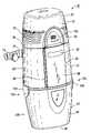
- FIG. 1is a front perspective view of a vacuum system according to an embodiment of the present invention.
- FIG. 2is another front perspective view of the vacuum system shown in FIG. 1 .
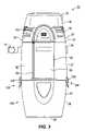
- FIG. 3is a front view of the vacuum system shown in FIG. 1 .
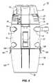
- FIG. 4is a rear view of the vacuum system shown in FIG. 1 .
- FIG. 5is a rear perspective view of the vacuum system shown in FIG. 1 .
- FIG. 6is another rear perspective view of the vacuum system shown in FIG. 1 .
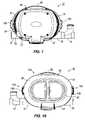
- FIG. 7is a top view of the vacuum system shown in FIG. 1 .
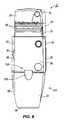
- FIG. 8is a left side view of the vacuum system shown in FIG. 1 .
- FIG. 9is a right side view of the vacuum system shown in FIG. 1 .
- FIG. 10is a bottom view of the vacuum system shown in FIG. 1 .
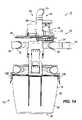
- FIG. 11is a front perspective view of the vacuum system shown in FIG. 1 with a portion of the housing removed.
- FIG. 12is a side perspective view of the vacuum system shown in FIG. 1 with a portion of the housing removed.
- FIG. 13is a top perspective view of the vacuum system shown in FIG. 1 with a portion of the housing removed.
- FIG. 14is a rear view of the vacuum system shown in FIG. 1 with a portion of the housing removed.
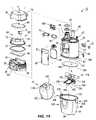
- FIG. 15is an exploded perspective view of the vacuum system shown in FIG. 1 .
- FIG. 15Ais an enlarged perspective view of the vacuum bag shown in FIG. 15 .
- FIG. 16is an enlarged front view of a control panel of the vacuum system shown in FIG. 1 with a portion of the housing removed.
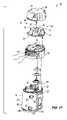
- FIG. 17is an exploded perspective view of a portion of the vacuum shown in FIG. 1 and illustrating air flow through the vacuum system.
- FIG. 18is an enlarged exploded perspective view of a lower portion of the vacuum system shown in FIG. 1 .
- FIGS. 19A-19Gillustrate a method of removing a bag from a vacuum system according to the present invention.
- FIG. 20is a front perspective view of a vacuum system according to another embodiment of the present invention.
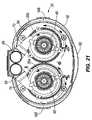
- FIG. 21is a top view of a portion of the vacuum system shown in FIG. 20 and illustrating travel paths of the airflow generated by the vacuum motors of the vacuum system.
- FIG. 22is a front perspective view of a vacuum system according to still another embodiment of the present invention.
- FIG. 23is a front perspective view of the vacuum system shown in FIG. 22 .
- vacuum bag and elements of the vacuum bag referred to in the present inventioncan be installed and operated in any orientation desired.
- terms such as “first”, “second”, and “third”are used herein and in the appended claims for purposes of description and are not intended to indicate or imply relative importance or significance.
- FIGS. 1-19Gillustrate a portion of a vacuum system 10 and a vacuum bag 12 according to some embodiments of the present invention.
- the vacuum system 10can be installed or used in any inhabitable structure, such as, for example, a home, a commercial building, and the like.
- the vacuum system 10can include a duct system 14 , which extends throughout the structure into various rooms of the structure. Vacuum inlets can be located in various locations throughout the structure and can be in fluid communication with the duct system 14 so that a vacuum hose or nozzle can be connected to the duct system 14 . As explained in greater detail below, to operate the vacuum system 10 , an operator inserts a hose or nozzle into one of the inlets or actuates a switch adjacent to an inlet. The vacuum system 10 then draws air and debris through the hose, nozzle, or inlet and through the duct system 14 toward a collection area.
- the vacuum system 10can have a housing 18 having any shape desired, such as a round shape, a rectangular, triangular, or other polygonal shape, an irregular shape, and the like.
- the housing 18 of the illustrated embodimenthas a generally elongated configuration and has an elliptical cross sectional shape.
- the housing 18can have a relatively small profile so that the housing 18 can be installed or located in relatively confined areas.
- the housing 18comprises a first module or housing portion 20 , a second module or housing portion 22 , and a third module or housing portion 24 .
- the first and second modules 20 , 22at least partially define a drive space or motor chamber 26
- the second and third housing portions 22 , 24substantially enclose a collection chamber 28 .
- the housing 18can include ribs 30 or other structural supports extending through one or more of the first, second, and third modules 20 , 22 , 24 .
- the housing 18 of the central vacuum system 10can be installed in a number of locations throughout the structure, such as, for example, in the garage, basement, or utility room of a home or a business, or alternatively, the housing 18 can be installed in a closet.
- the illustrated embodimentincludes a number of inlet openings 32 , each of which can be connected to the duct system 14 to fluidly connect the housing 18 (and the vacuum motor 48 , which is described in greater detail below) to the duct system 14 .
- inlets 32are located on the left and right sides of the housing 18 . In other embodiments, inlets 32 can extend through other portions of the housing 18 and can have other orientations to provide further installation options.
- an elastomeric materiale.g., santaprene, neoprene, and polymers of butyl and supronyl, and the like
- santaprene, neoprene, and polymers of butyl and supronyl, and the likeis positioned between an outer wall of an inlet 32 and the connector 34 to provide a seal and to prevent and/or reduce movement of air and debris between the inlet 32 and the connector 34 .
- the connector 34 and the elastomeric materialcan be sealingly connected to the duct system 14 without requiring additional clamps, clamping tools, and other conventional sealing devices and elements, although such sealing devices and elements can also be used.
- the connector 34 and the elastomeric material of the illustrated embodimentcan be manufactured relatively easily and inexpensively and do not require complex tooling and assembly.
- An elastomeric materialcan also or alternately be positioned between the connector 34 and a portion of the duct system 14 to sealingly connect the connector 34 and the duct system 14 . Covers 35 are then placed over the other inlets 32 to seal these inlets 32 .
- the first module 20includes a cap 36 , a motor cage 38 , and a baffle 40 positioned between the cap 36 and the motor cage 38 .
- An upper wall 54 of the second module 22 and the motor cage 38 of the first module 20substantially enclose the vacuum motor 48 and define a drive space 26 having a substantially elliptical cross sectional shape.
- the vacuum motor 48is positioned on a left side of drive space 26 .
- the vacuum motor 48can have other orientations within the drive space 26 .
- the vacuum motor 48can be positioned in a central location in the drive space 26 or the vacuum motor 48 can be positioned on a right side of the drive space 26 .
- two or more vacuum motors 48can be positioned in the drive space 26 .
- the vacuum motors 48can be supported on the upper wall 54 of the second module 22 and can be spaced apart so that airflow generated by one motor 48 does not interfere with airflow generated by the other motor 48 .
- the airflow generated by the motors 48follows two generally circular travel paths (represented by arrows 56 a , 56 b in FIG. 21 ). As shown in FIG.
- the travel paths 56 a , 56 bextend through substantially the entire drive space 26 , thereby preventing the formation of dead spaces wherein the vacuum motors 48 do not generate airflow.
- Such a constructioncan improve the efficiency of one or both of the vacuum motors 48 and can reduce noise generation.
- Some embodimentsspace two or more vacuum motors 48 close enough that airflow generated by one vacuum motor 48 interferes with the airflow generated by the other motor 48 . This interference creates a lower air velocity region that drops debris entrained in the airflow.
- elements of the vacuum system 12can be constructed so that common elements can be used in constructions of the vacuum system 12 having one or more vacuum motors 48 located in any number of locations in the drive space 26 . In these embodiments, no or relatively minor modifications are made to assemble various vacuum systems 12 having a number of different configurations.
- a networkextends throughout the structure.
- the housing 18can support an electrical adapter 57 , which is electrically connectable to the network for communication with control switches positioned throughout the structure.
- control switchescan be positioned in inlets so that when an operator opens an inlet to connect a hose or nozzle to the duct system, the control switch is triggered, thereby transmitting an activation system through the network to the vacuum motor 48 .
- control switchescan be located on wall switches or in other locations throughout the structure.
- cooling vents 58can extend through the housing 18 to cool the vacuum motor 48 .
- the cooling vents 58extend through the motor cage 38 and the cap 36 and communicate between atmosphere and the drive space 26 .
- airis drawn into the drive space 26 through the cooling vents 58 as represented by arrows 60 in FIG. 17 .
- the airis then drawn through the drive space 26 between an upper surface of the motor cage 38 and a lower surface of the baffle 40 before being drawn downwardly through an opening 62 in the upper surface of the motor cage 38 and into the vacuum motor 48 .
- acoustic dampening materiale.g., elastomeric materials, such as, for example, polyester, polyurethane, melamine, and the like
- acoustic dampening material 64can be positioned in the drive space 26 to absorb noise generated by air flowing through the drive space 26 .
- acoustic dampening material 64is secured to the undersides of the baffle 40 and the cap 36 .
- acoustic dampening material 64can be positioned in other locations in the drive space 26 to absorb noise generated by air flowing through the drive space 26 .
- the vacuum system 10can also include an exhaust system 66 , which provides an exit for air exhausted from the vacuum motor 48 . As shown in FIG. 17 , exhaust air (represented by arrows 67 ) exits the vacuum motor 48 and is directed upwardly and outwardly through the exhaust system 66 toward the atmosphere.
- the vacuum system 10can also include an acoustic dampening system 68 positioned along the exhaust system 66 for absorbing noise generated by exhaust air exiting the housing 18 through the exhaust system 66 .
- the exhaust system 66 and the acoustic dampening system 68include a conduit 70 and a muffler 69 , which direct exhaust air 67 upwardly and outwardly from the vacuum motor 48 and dampen noise generated by the exhaust air 67 .
- the muffler 69extends through openings in the cap 36 and the baffle 40 .
- the exhaust system 66 and the acoustic dampening system 68 of the illustrated embodimentalso include an elbow 71 connected to a downstream end of the muffler 69 and a dampening chamber 72 defined between a first dampening wall 73 and a second dampening wall 74 .
- the elbow 71directs the exhaust air 67 laterally into the dampening chamber 72 , which provides a substantially U-shaped path for exhaust air 67 .
- the first and second dampening walls 73 , 74can have other shapes and orientations to provide other non-linear paths (e.g., semicircular, L-shaped, and the like) for the exhaust air 67 .
- portions of the dampening chamber 72can also include or be covered with acoustic dampening material (e.g., elastomeric materials, such as, for example, polyester, polyurethane, melamine, and the like) to absorb noise generated by the exhaust air 67 .
- acoustic dampening materiale.g., elastomeric materials, such as, for example, polyester, polyurethane, melamine, and the like
- the exhaust system 66 and the acoustic dampening system 68 of the illustrated embodimentdirect the exhaust air 67 outwardly through an opening 76 in the cap 36 toward the atmosphere.
- the second module 22defines an upper portion of the collection chamber 28 and includes an upper wall 54 and a side wall 80 having a downwardly extending ridge 82 .
- An opening 84extends through the side wall 80 and provides access to the collection chamber 28 and, in embodiments having vacuum bags 12 , provides access to vacuum bags 12 located in the collection chamber 28 .
- the opening 84also provides access to other elements and systems of the vacuum system 10 , such as, for example, the vacuum motor 48 and the controller 160 (described below) so that operators can perform maintenance operations.
- the second module 22includes a door 88 , which is connected to the side wall 80 .
- the door 88is moveable relative to the side wall 80 between a closed position, in which the door 88 substantially covers the opening 84 , and an opened position, in which the door 88 is moved away from the opening 84 .
- FIGS. 19A-19Fthe door 88 is moveable relative to the side wall 80 between a closed position, in which the door 88 substantially covers the opening 84 , and an opened position, in which the door 88 is moved away from the opening 84 .
- the door 88also includes a handle 90 for moving the door 88 between the opened and closed positions and a viewing window 92 so that operators can view the contents of the collection chamber 26 (e.g., the vacuum bag 12 and/or debris collected in the collection chamber 28 ) without having to open the door 88 .
- a handle 90for moving the door 88 between the opened and closed positions and a viewing window 92 so that operators can view the contents of the collection chamber 26 (e.g., the vacuum bag 12 and/or debris collected in the collection chamber 28 ) without having to open the door 88 .
- the second module 22can also include a seal or gasket 94 secured in the opening 84 , or alternatively, secured to the door 88 for movement with the door 88 relative to the side wall 80 .
- the gasket 94provides a seal and prevents and/or reduces movement of air and debris through the opening 84 when the door 88 is in the closed position.
- the third module 24defines the lower portion of the collection chamber 28 and includes a bottom wall 96 and a side wall 98 . Together, the bottom and side walls 96 , 98 can define a pail 100 , which is operable to collect and contain debris and/or support a vacuum bag 12 . In some embodiments, the third module 24 can also support one or more replacement bags 12 . In other embodiments, replacement bags 12 can be housed in other locations throughout the housing 18 .
- the vacuum system 10can include a locking assembly 104 for securing the third module 24 to the second module 22 .
- the vacuum system 10includes two locking assemblies 104 positioned between the second and third modules 22 , 24 .
- the vacuum system 10can include one, three, or more locking assemblies 104 .
- the locking assembly 104 of the illustrated embodiment of FIGS. 1-15 , 18 , and 19 A- 19 Ginclude protrusions 106 extending outwardly from the side wall 80 of the second module 22 and latches 108 connected to the side wall 98 of the third module 24 .
- the locking assemblies 104can include protrusions 106 extending outwardly from the side wall 98 of the third module 24 and latches 108 connected to the side wall 80 of the second module 22 .
- the locking assembly 104can include other inter-engaging elements and fasteners, such as for example, screws, nails, rivets, pins, posts, clips, clamps, and any combination of such fasteners.
- the latches 108are pivotably connected to the side wall 98 for movement between locking positions (shown in FIGS. 1-14 ), in which the latches 108 lockingly engage the protrusions 106 to secure the third module 24 to the second module 22 , and unlocking positions (not shown), in which the latches 108 are moved away from and out of engagement with the protrusions 106 , thereby allowing the third module 24 to be separated from the second module 22 .
- the locking assemblies 104are operable to lift the third module 24 from a floor, table, or shelf and to move the third module 24 toward the second module 22 .
- an operatorpositions the third module 24 under the second module 22 and positions the upper ends of the latches 108 on the protrusions 106 . The operator then pivots the latches 108 downwardly from the unlocking positions toward the locking positions to lift the third module 24 upwardly and into engagement with the second module 22 .
- a lip 110extends upwardly from the side wall 98 of the third module 24 and is engageable with the ridge 82 and the side wall 80 of the second module 22 to form a seal between the second and third modules 22 , 24 and to prevent and/or reduce movement of air and debris between the second and third modules 22 , 24 .
- the vacuum system 10can also include a gasket or seal 112 positioned between the lower end of the second module 22 and an upper end of the third module 24 .
- the vacuum system 12can also include an adapter 116 , which extends into the collection chamber 28 and is engageable with a vacuum bag 12 to fluidly connect the vacuum motor 48 and the duct system 14 to the vacuum bag 12 .
- the adapter 116can extend through an upper portion of the second module 22 and can be oriented to direct debris downwardly into the collection chamber 28 and/or the bag 12 .
- the adapter 116can have other orientations and can extend through other portions of the collection chamber 28 .
- the vacuum system 10can also include a bag mounting assembly 118 , which extends into the upper portion of the collection chamber 28 and is operable to support a vacuum bag 12 in the housing 18 .
- the bag mounting assembly 118includes a mounting plate 120 , which is connected to the adapter 116 and the side wall 80 of the second module 22 , and a bag plate 122 , which is pivotably connected to the side wall 98 of the second module 22 for pivoting movement relative to the side wall 80 and the mounting plate 120 between a locking position, in which the bag plate 122 is adjacent to the mounting plate 120 , and an unlocking position, in which at least a portion of the bag plate 122 is moved away from the mounting plate 120 .
- the bag plate 122defines a central opening 126 and includes rails 130 located on opposite sides of the opening 126 .
- a bag 12 or a portion of a bag 12can be inserted through the opening 126 in the bag plate 122 and the bag plate 122 can be moved from the unlocking position toward the locking position to trap or lock the bag 12 or a portion of the bag 12 between the bag plate 122 and the mounting plate 120 and to connect the bag 12 to the adapter 116 .
- the vacuum bag 12includes a body 132 enclosing an interior space and having an opening through which debris can pass.
- the bag 12also includes a flange 134 positioned adjacent to the opening in the body 132 .
- the flange 134defines an inlet 136 and supports a cover 138 for sliding movement relative to the flange 134 . As shown in FIG.
- the cover 138includes an opening 140 and is moveable relative to the flange 134 between an opened position, in which the opening 140 of the cover 138 is substantially aligned with the inlet 136 of the flange 134 , and a closed position, in which the opening 140 of the cover 138 is moved out of alignment with the inlet 136 of the flange 134 so that at least a portion of the cover 138 substantially covers the inlet 136 of the flange 134 .
- the flange 134can be secured to the bag plate 122 for movement with the bag plate 122 between the locking position and the unlocking position.
- the flange 126is inserted between the rails 130 and is moved rearwardly along the rails 130 into engagement with the bag plate 122 .
- the bag plate 122can then be moved from the unlocking positioned toward the locking position to secure the bag 12 to the adapter 116 so that at least a portion of the adapter 116 extends through the opening 140 of the cover 138 and the inlet 136 of the flange 140 to direct debris into the bag 12 .
- a latch or fastener 144can secure the bag plate 122 to the mounting plate 118 .
- the bag mounting assembly 118can include a protrusion 146 , which extends outwardly from the bag plate 122 and which is engageable in a recess 148 in the cover 138 of the bag 12 .
- the protrusion 146engages the recess 148 so that when the flange 134 is removed from the bag plate 122 , the engagement between the protrusion 146 of the bag plate 122 and the recess 148 of the cover 138 will cause the cover 138 to move relative to the flange 134 between the opened position and the closed position.
- the cover 138can be moved across the inlet 136 in the flange 134 before the bag 12 is removed from the collection chamber 28 , thereby preventing debris from exiting the bag 12 through the inlet 136 as the bag 12 is removed from the vacuum system 10 .
- the vacuum system 10can also include a filter 154 positioned between the vacuum motor 48 and the vacuum bag 12 .
- the filter 154substantially prevents debris from moving from the collection chamber 28 into the drive space 26 , thereby preventing debris from moving from the collection chamber 28 into the vacuum motor 48 or from a bag 12 located in the collection chamber 28 into the vacuum motor 48 .
- the filter 154can also prevent debris from entering the drive space 26 when a bag 12 located in the collection chamber 28 is punctured or torn.
- the filter 154is removeably secured in the collection chamber 28 between brackets and is accessible through the opening 84 in the side wall 88 of the second module 22 .
- an operatorcan open the door 80 to clean or change the filter 154 when the filter 154 becomes soiled, or alternatively, an operator can clean the filter 154 each time the operator inserts a new bag 12 into the collection chamber 28 or each time the operator removes debris from the collection chamber 28 .
- the filter 154can include a tab 156 , which extends downward into the collection chamber 28 .
- the tab 156is oriented to be accessible through the opening 84 .
- an operatorcan clean the filter 154 by inserting a hand into the collection chamber 28 through the door 88 and tapping or shaking the filter 154 . Debris trapped in the filter 154 will then fall to the bottom of the collection chamber 26 .
- the vacuum system 10can also include a controller 160 operable to control and monitor operation of the vacuum system 10 and a display panel 162 for displaying system data relating to the operation of the vacuum system 10 .
- the controller 160is located in the first module 20 and the display panel 162 is positioned on the outer wall of the motor cage 38 .
- the controller 160 and the display 162can have other orientations and can be supported in other locations in the housing 18 .
- the vacuum system 10can also include a number of sensors 164 distributed throughout the housing 18 for monitoring and controlling operation of the vacuum system 10 .
- a pressure sensor 164is supported in the collection chamber 28 and is connected to the controller 160 to transmit pressure data to the controller 160 .
- the controller 160is operable to calculate the volume of debris collected in the collection chamber 28 and/or the volume of debris collected in a bag 12 supported in the collection chamber 28 using the data received from the pressure sensor 164 .
- the controller 160can calculate the volume of empty space or debris capacity remaining in the collection chamber 28 or in a bag 12 supported in the collection chamber 28 .
- a base pressure value corresponding to an empty collection chamber 28 or empty bag 12is stored in the controller memory unit.
- the pressure sensor 164records these increases and transmits the pressure data to the controller 160 .
- the controller 160continuously compares the pressure data from the sensor 164 to the base pressure value to calculate the volume of debris in the collection chamber 28 or in a bag 12 supported in the collection chamber 28 .
- the controller 160continuously compares the pressure data from the sensor 164 to the base pressure value to calculate the volume of empty space or capacity remaining in the collection chamber 28 or in a bag 12 supported in the collection chamber 28 as debris is collected.
- a maximum pressure value corresponding to a full collection chamber 28 or a full bag 12is stored in the controller memory unit.
- the pressure sensor 164records the increases in pressure as debris is collected in the collection chamber 28 , or alternatively, in a bag 12 supported in the collection chamber 28 .
- the pressure sensor 164transmits the pressure data to the controller 160 and the controller 160 continuously compares the pressure data from the sensor 164 to the maximum pressure value to calculate the volume of debris in the collection chamber 28 or in a bag 12 supported in the collection chamber 28 .
- the controller 160continuously compares the pressure data from the sensor 164 to the maximum pressure value to calculate the volume of empty space or capacity remaining in the collection chamber 28 or in a bag 12 supported in the collection chamber 28 as debris is collected.
- the display panel 162displays the remaining capacity in the collection chamber 28 or in the bag 12 supported in the collection chamber 28 , or alternatively, displays the volume of debris in the collection chamber 28 or in the bag 12 supported in the collection chamber 28 .
- the display panel 162includes a number of lights (e.g., light emitting diodes or “LEDs”), which are illuminated to inform the operator of the remaining capacity or to inform the operator of the volume of debris collected.
- the display panel 162can include one or more green lights, one or more amber lights, and one or more red lights, which are sequentially illuminated to indicate the changing collection chamber capacity.
- the display panel 162can include other indicators or display screens (e.g., a video screen, a liquid crystal display, or the like) which are operable to display data corresponding to collection chamber capacity.
- the vacuum motor 48can become overheated and/or damaged when the vacuum system 10 is operated after the collection chamber 28 or a bag 12 supported in the collection chamber 28 is filled to a maximum allowable capacity.
- the controller 160is operable to shutdown the vacuum motor 48 when the collection chamber 28 or a bag 12 supported in the collection chamber 28 is fill to prevent damage to the vacuum motor 48 .
- a maximum allowable pressure value corresponding to a maximum allowable capacity of debrisis stored in the controller memory unit.
- the controller 160shuts down the vacuum motor 48 .
- the controller 160can be programmed to display a warning message or to activate a warning light when the pressure sensor 164 records a pressure value in the collection chamber 28 which is greater than or equal to the maximum allowable pressure value.
- the vacuum system 10includes temperature sensors 168 , which are positioned in the drive space 26 and are operable to record the temperature of the vacuum motor 48 .
- a maximum temperature value corresponding to a maximum allowable motor temperatureis stored in the controller memory unit.
- the controller 160shuts down the vacuum motor 48 to prevent or reduce damage to the vacuum motor 48 .
- the controller 160can be programmed to display a warning message or to activate a warning light when the temperature sensor 168 records a temperature value in the collection chamber 28 which is greater than or equal to the maximum allowable temperature value.
- other sensorscan be positioned in the collection chamber 28 to record data corresponding to the capacity of the collection chamber 28 or a bag 12 supported in the collection chamber 28 to monitor operation of the vacuum system 10 .
- the vacuum system 12can include microphones positioned in the collection chamber 28 .
- sound datais transmitted from the microphones to the controller 160 and the controller 160 calculates the capacity of the collection chamber 28 or a bag 12 supported in the collection chamber 28 .
- the controller 160can also include a timer.
- a maximum motor operation timeis stored in the controller memory unit and the controller 160 is programmed to alert the operator or shut down the vacuum motor 48 when the vacuum motor 48 is operated longer than the maximum motor operation time.
- the controller 160can be programmed to shut down the vacuum motor 48 if the vacuum motor 48 is continually operated for 3 hours.
- the controller 160can be programmed to shut down the vacuum motor 48 when the vacuum motor 48 is operated for more than 3 hours during a 4 hour period.
- the controller 160can be programmed to estimate the length of time the vacuum motor 48 is operated between bag replacements or occasions in which the collection chamber 28 is emptied. In these embodiments, the controller 160 can be programmed to progressively illuminate lights on the control panel 162 corresponding to the length of time the vacuum motor 48 has been operated between bag replacements or occasions in which the collection chamber 28 is emptied. For example, in some embodiments, the controller 160 is programmed to illuminate a first green light after one hour of vacuum motor operation, a second green light after a second hour of vacuum motor operation, an amber light after a third hour of vacuum motor operation, and a red light after a fourth hour of vacuum motor operation.
- the vacuum system 10can also include a reset button 170 .
- the reset button 170is located on the display panel 162 .
- the reset button 170can be located in other locations on the housing 18 .
- the reset button 170can be located on the hose which is connected to the duct system 14 so that the operator can reset the vacuum system 10 without having to walk to the housing 18 .
- an operatorcan press the reset button 170 to restart the vacuum motor 48 after replacing the full vacuum bag 12 with a new bag 12 or after the operator empties the collection chamber 28 .
- the controller 160can be programmed to record a new pressure value in the collection chamber 28 after the reset button 170 has been pressed. If after being shut down, the pressure sensor 146 again records a pressure value greater than the maximum allowable pressure value, the controller 160 can be programmed to shut down the vacuum motor 48 or to alert the operator. In other embodiments having other sensors, such as, for example, temperature sensors or microphones, the controller 160 can be programmed to record new values after the reset button 170 is pressed and to compare these new values to predetermined maximum values.
- the controller 160can be programmed to shut down the vacuum motor 48 a second time, or alternatively, to alert the operator (e.g., by illuminating a warning light on the display panel 162 .
- an operatoropens the door 88 to insert a new bag 12 into the collection chamber 28 .
- the operatorthen pivots the bag plate 122 downwardly from the locking position toward the unlocking position.
- the operatorinserts a vacuum bag 12 into the collection chamber 28 so that the body 132 extends downwardly into the third module 24 and aligns the flange 134 of the vacuum bag 12 with the rails 130 of the bag plate 122 .
- the operatorthen moves the flange 134 into engagement with the bag plate 122 .
- the cover 138is moved forwardly with respect to the flange 134 to align the opening 140 in the cover 138 with the inlet 136 in the flange 134 and to engage the protrusion 146 of the bag mounting assembly 118 in the recess 148 in the cover 138 .
- the operatornext pivots the bag plate 122 upwardly toward the locking position, moving the flange 134 into engagement with the adapter 116 so that at least a portion of the adapter 116 extends through the inlet 136 in the flange 134 and through the opening 140 in the cover 138 .
- the operatorsecures the bag plate 122 in the locking position with the latch 144 and closes the door 88 , sealing the bag 12 in the collection chamber 28 .
- the operatorcan then operate the vacuum system 10 in a conventional manner to draw debris into a hose, nozzle, or other port and through the duct system 14 toward the adapter 116 , which directs the debris into the vacuum bag 12 .
- the vacuum system 10fills the bag 12 with debris.
- the controllercan be operable to alert the operator when the bag 12 is filled and when bag replacement is necessary, as mentioned above.
- the operatorcan open the door 88 to determine when bag replacement is necessary or the operator can look through the viewing window 92 in the door 88 to determine when bag replacement is required.
- the operatorWhen bag replacement is required, the operator shuts down the vacuum motor 48 and opens the door 88 . The operator then grasps the latch 144 to unlock the bag assembly 118 and pivots the bag plate 122 and the bag flange 134 downwardly toward the unlocking position. The operator then slides the bag flange 134 forwardly along the rails 130 and away from the bag mounting assembly 118 .
- the protrusion 146 on the bag mounting assembly 118remains engaged in the recess 148 in the cover 138 , causing the cover 138 to move relative to the flange 134 from the opened position toward the closed position so that the cover 138 extends across and substantially covers the inlet 136 in the flange 134 .
- the operatorthen removes the bag flange 134 from the bag mounting assembly 118 and lets the bag 12 fall to the bottom of the collection chamber 28 (i.e., the bottom of the third module 24 ).
- the operatormoves the locking assemblies 104 from the locking positions toward the unlocking positions and removes the third module 24 (and consequently the bag 12 supported in the third module 24 ) from the second module 22 .
- the operatorcan then remove the bag 12 from the third module 24 and dispose of the bag 12 in a conventional manner.
- the operatorreconnects the third module 24 to the second module 22 and moves the locking assemblies 104 toward the locking positions to secure the third module 24 to the second module 22 .
- the operatorcan then insert a new bag 12 into the collection chamber 28 , as explained above.
- the operatoroperates the vacuum system 10 in a conventional manner to draw debris into a hose or nozzle and through the duct system 14 toward the adapter 116 , which directs the debris into the collection chamber 28 .
- the vacuum system 10fills the collection chamber 28 with debris.
- the controllercan be operable to alert the operator when the collection chamber 28 is filled and when it is necessary to empty the collection chamber 28 , as mentioned above.
- the operatorcan open the door 88 to determine when it is necessary to empty the collection chamber 28 , or alternatively, the operator can look through the viewing window 92 in the door 88 to determine when it is necessary to empty the collection chamber 28 .
- the operatorWhen it is necessary to empty the collection chamber 28 , the operator shuts down the vacuum motor 48 . The operator then moves the locking assemblies 104 from the locking positions toward the unlocking positions and removes the third module 24 (and the debris contained in the third module 24 ) from the second module 22 . The operator can then empty the third module 24 and dispose of the debris in a conventional manner.
- the operatorreconnects the third module 24 to the second module 22 and moves the locking assembly 104 toward the locking position to secure the third module 24 to the second module 22 .
- the operatorcan then resume operation of the vacuum system 10 .
- FIGS. 22 and 23illustrate another embodiment of the vacuum system 10 A according to the present invention.
- the vacuum system 10 A in FIGS. 22 and 23is similar in many ways to the illustrated embodiments of FIGS. 1-21 described above. Accordingly, with the exception of mutually inconsistent features and elements between the embodiment of FIGS. 22 and 23 and the embodiments of FIGS. 1-21 , reference is hereby made to the description above accompanying the embodiments of FIGS. 1-21 for a more complete description of the features and elements (and the alternatives to the features and elements) of the embodiment of FIGS. 22 and 23 .
- Features and elements in the embodiment of FIGS. 22 and 23 corresponding to features and elements in the embodiments of FIGS. 1-21are identified by the same reference number and the letter “A”.
- FIGS. 22-23illustrate a vacuum system 10 A having a housing 18 A, which defines a first module 20 A, a second module 22 A, and a third module 24 A. Together, the first and second modules 20 A, 22 A at least partially define a drive space or motor chamber 26 A. Together, the second and third housing portions 22 A, 24 A substantially enclose a collection chamber 28 A.
- the vacuum system 10 Aincludes a cyclonic drive system 210 , including a vacuum motor 48 A, which is operable to draw debris through the duct system 14 and into the collection chamber 28 A.
- a cyclonic drive system 210including a vacuum motor 48 A, which is operable to draw debris through the duct system 14 and into the collection chamber 28 A.
- other drive systemsincluding conventional vacuum drive systems can also or alternately be used.
- the second module 22 Adefines an upper portion of the collection chamber 28 A and includes an upper wall 54 A and a side wall 80 A.
- An opening 84 Aextends through the side wall 80 A and provides access to the collection chamber 28 A and to a filter 12 A supported in the collection chamber 28 A.
- a door 88 Ais connected to the side wall 80 A and is moveable relative to the side wall 80 A between a closed position, in which the door 88 A substantially covers the opening 84 A, and an opened position, in which the door 88 A is moved away from the opening 84 A.
- the third module 24 Adefines the lower portion of the collection chamber 28 A and includes a bottom wall 96 A and a side wall 98 A. Together, the bottom and the side walls 96 A, 98 A can define a pail 100 A, which is operable to collect and contain debris. As shown in the illustrated embodiment of FIGS. 22 and 23 , the vacuum system 10 A can include a locking assembly 104 A for securing the third module 24 A to the second module 22 A.
- the vacuum system 10 Acan also include a filter mounting assembly 118 A for supporting a filter 12 A in the collection space 28 A.
- the filter mounting assembly 118 Aincludes a generally cylindrical mounting plate 120 A secured to the side wall 80 A of the second module 22 A and extending circumferentially around the collection chamber 28 A.
- the mounting plate 120 Acan have other shapes and can be positioned in other locations in the collection chamber 28 A.
- the mounting plate 120 Acan also include a number of radially extending ribs 212 .
- a filter 12 A formed of a flexible or elastomeric materialcan be secured to the mounting plate 120 A and can include a body 214 enclosing an interior space and an edge 216 defining an opening 218 .
- a body 214enclosing an interior space and an edge 216 defining an opening 218 .
- a fastener 220such as, an elastic band, secures the edge 216 of the filter 12 A to the mounting plate 120 A between the ribs 212 for movement relative to the mounting plate 120 A between an inflated orientation, in which at least a portion of the filter 12 A extends upwardly from the mounting plate 12 A through the collection chamber 28 A, and a deflated orientation, in which the filter 12 A hangs downwardly from the mounting plate 120 A through a lower portion of the collection chamber 28 A.
- other conventional fastenerscan be employed to secure the filter 12 A to the mounting plate 120 A as just described, such as pins, posts, clips, clamps, inter-engaging elements, and any combination of such fasteners.
- the filter 12 Acan include a weight 222 , which is secured to a lower end of the filter 12 A and is operable to maintain the filter 12 A in the deflated orientation when the vacuum system 10 is not in operation.
- the side wall 80 A of the second module 22 Adefines an inlet 228 communicating between atmosphere and the collection chamber 28 A.
- the mounting plate 120 Acan also define an opening 230 , which is generally aligned with the inlet in the second wall 80 A.
- a conduit 234extends radially through the inlet 228 in the side wall 80 A of the second module 22 A and, in embodiments having a mounting plate 120 A, through the opening 230 into the collection chamber 28 A.
- an operatorconnects a hose or nozzle to the duct system 14 and activates the vacuum motor 48 A, which operates to draw debris and air through the duct system 14 and into the collection chamber 28 A through the conduit 234 .
- the vacuum system 10 Ahaving a filter mounting assembly 118 A and a filter 12 A supported in the collection chamber 28 A, air and debris entering the collection chamber 28 A move the filter 12 A relative to the mounting plate 120 A from the deflated orientation toward the inflated orientation.
- the filter 12 Acan then operate as a filter, allowing air to move upwardly through the collection chamber 28 A and outwardly toward the exhaust system 66 A while preventing debris from exiting the collection chamber 28 A.
- the filter 12 Acan prevent or reduce movement of debris from the collection chamber 28 A into the drive space 26 A.
- air and debris entering the collection chamber 28 Ais directed along a generally circular flow path within the collection chamber 28 A.
- centrifugal forcescause the debris to be separated from the air.
- the vacuum system 10 Acan include other conventional drive systems and filter systems, which can operate to separate the debris from the air in the collection chamber 28 A.
- the operatorshuts down the vacuum motor 48 A and removes the third module 24 A from the second module 22 A. The operator can then empty the third module 24 A and dispose of the debris in a conventional manner.
- the operatorcan open the door 88 A and can reach into the collection chamber 28 A through the opening 84 A.
- the operatorcan then tap an upper or clean side of the filter 12 A to dislodge any debris accumulated on the filter 12 A.
- the debriswill then drop into the third module 24 A and can be disposed as described above.
Landscapes
- Engineering & Computer Science (AREA)
- Mechanical Engineering (AREA)
- Vacuum Packaging (AREA)
- Containers, Films, And Cooling For Superconductive Devices (AREA)
- Filters For Electric Vacuum Cleaners (AREA)
- External Artificial Organs (AREA)
Abstract
Description
Claims (32)
Priority Applications (4)
| Application Number | Priority Date | Filing Date | Title |
|---|---|---|---|
| US11/032,511US7461430B2 (en) | 2005-01-10 | 2005-01-10 | Vacuum system and method |
| CA2593764ACA2593764C (en) | 2005-01-10 | 2006-01-10 | Vacuum system and method |
| PCT/US2006/000644WO2006076279A2 (en) | 2005-01-10 | 2006-01-10 | Vacuum system and method |
| US11/731,185US20080016646A1 (en) | 2005-01-10 | 2007-03-30 | Housing assembly for a vacuum |
Applications Claiming Priority (1)
| Application Number | Priority Date | Filing Date | Title |
|---|---|---|---|
| US11/032,511US7461430B2 (en) | 2005-01-10 | 2005-01-10 | Vacuum system and method |
Related Child Applications (1)
| Application Number | Title | Priority Date | Filing Date |
|---|---|---|---|
| US11/731,185Continuation-In-PartUS20080016646A1 (en) | 2005-01-10 | 2007-03-30 | Housing assembly for a vacuum |
Publications (2)
| Publication Number | Publication Date |
|---|---|
| US20060150360A1 US20060150360A1 (en) | 2006-07-13 |
| US7461430B2true US7461430B2 (en) | 2008-12-09 |
Family
ID=36651702
Family Applications (1)
| Application Number | Title | Priority Date | Filing Date |
|---|---|---|---|
| US11/032,511Active2026-11-11US7461430B2 (en) | 2005-01-10 | 2005-01-10 | Vacuum system and method |
Country Status (3)
| Country | Link |
|---|---|
| US (1) | US7461430B2 (en) |
| CA (1) | CA2593764C (en) |
| WO (1) | WO2006076279A2 (en) |
Cited By (15)
| Publication number | Priority date | Publication date | Assignee | Title |
|---|---|---|---|---|
| US20080098560A1 (en)* | 2006-11-01 | 2008-05-01 | U.S. Products | Motor manifold |
| US20090076656A1 (en)* | 2007-09-14 | 2009-03-19 | Seagate Technology Llc | Collecting debris from a tool |
| US20110110091A1 (en)* | 2008-07-03 | 2011-05-12 | Koninklijke Philips Electronics N.V. | Dust mite killing carpet |
| US8726457B2 (en) | 2011-12-30 | 2014-05-20 | Techtronic Floor Care Technology Limited | Vacuum cleaner with display |
| WO2014113304A1 (en)* | 2013-01-18 | 2014-07-24 | Electrolux Home Care Products, Inc. | Central vacuum cleaner apparatus |
| US9078550B2 (en) | 2011-11-11 | 2015-07-14 | Electrolux Home Care Products, Inc. | Latch assembly for a vacuum system |
| WO2015148501A1 (en)* | 2014-03-24 | 2015-10-01 | International Cleaning Equipment Holdings Co. Ltd., Dba International Cleaning Equipment | Floor cleaning machines having intelligent systems |
| US10582823B2 (en) | 2017-03-03 | 2020-03-10 | Tti (Macao Commercial Offshore) Limited | Vacuum cleaner including a surface cleaning head having a display |
| US20200096008A1 (en)* | 2018-09-25 | 2020-03-26 | Abb Schweiz Ag | Modular Low-Noise Motor |
| US11051670B2 (en) | 2017-04-13 | 2021-07-06 | Intelligent Cleaning Equipment Holdings Co. Ltd. | Floor cleaning machines having intelligent systems, associated sub-assemblies incorporating intelligent systems, and associated methods of use |
| US11058272B2 (en)* | 2016-03-28 | 2021-07-13 | Nelson Hulli | Convertible central vacuum unit |
| US11564540B2 (en)* | 2016-04-20 | 2023-01-31 | Fathhome, Inc. | Vacuum-based method and apparatus for cleaning soiled articles |
| US11944260B2 (en) | 2018-11-09 | 2024-04-02 | Dyson Technology Limited | Vacuum cleaner |
| US12075957B2 (en) | 2014-03-24 | 2024-09-03 | Intelligent Cleaning Equipment Holdings Co. Ltd. | Floor cleaning machines having intelligent systems, associated sub-assemblies incorporating intelligent systems, and associated methods of use |
| USD1047325S1 (en)* | 2021-08-24 | 2024-10-15 | Emerson Electric Co. | Backpack vacuum cleaner |
Families Citing this family (11)
| Publication number | Priority date | Publication date | Assignee | Title |
|---|---|---|---|---|
| USD534697S1 (en)* | 2005-01-10 | 2007-01-02 | Broan-Nutone Llc | Vacuum system |
| ITRA20070042A1 (en)* | 2007-06-01 | 2008-12-02 | Gen Aspirazione Di Bianchi Fa | CONTROL UNIT FOR CENTRALIZED VACUUM CLEANERS. |
| USD617962S1 (en)* | 2009-02-06 | 2010-06-15 | Electrolux Home Care Products, Inc. | Central vacuum |
| US20100199454A1 (en)* | 2009-02-06 | 2010-08-12 | Electrolux Home Care Products,Inc. | Latch Assembly for a Vacuum System |
| USD618408S1 (en)* | 2009-02-06 | 2010-06-22 | Electrolux Home Care Products, Inc. | Central vacuum |
| IT1399239B1 (en)* | 2009-05-14 | 2013-04-11 | Lavorwash Spa | ASPIRATOR TO VACUUM A GASEOUS FLUID AND SOLID PARTS |
| USD641110S1 (en)* | 2009-11-18 | 2011-07-05 | Widmar Inc. | Wall-mounted auxiliary vacuum unit |
| DE202013000481U1 (en)* | 2013-01-18 | 2013-01-25 | Robert Schmitt | Vacuum unit for a vacuum cleaner |
| CN109008797B (en)* | 2017-06-09 | 2024-07-02 | 天佑电器(苏州)有限公司 | Dust collector |
| US11058273B2 (en) | 2017-09-28 | 2021-07-13 | Techtronic Floor Care Technology Limited | Vacuum cleaner |
| USD895914S1 (en)* | 2018-02-15 | 2020-09-08 | The Charles Machine Works, Inc. | Vacuum system |
Citations (72)
| Publication number | Priority date | Publication date | Assignee | Title |
|---|---|---|---|---|
| US2253310A (en) | 1938-12-14 | 1941-08-19 | Hoover Co | Suction cleaner |
| US2884185A (en) | 1956-06-29 | 1959-04-28 | American Lincoln Corp | Suction tank head |
| US3213480A (en)* | 1964-04-27 | 1965-10-26 | Rhys D Miller | Wall mounted clothes cleaning vacuum appliance |
| US3358316A (en) | 1965-01-08 | 1967-12-19 | Atlas Floor Surfacing Machiner | Suction cleaner |
| US3570809A (en) | 1969-06-05 | 1971-03-16 | Clarkson Ind Inc | Silent hose coupling |
| US3882961A (en) | 1974-04-01 | 1975-05-13 | Servicemaster Ind | Muffler for vacuum-inducing motor |
| US3975790A (en) | 1974-10-11 | 1976-08-24 | Lawrence Patterson | Cleaning apparatus having ultraviolet lamp fixture |
| US4015683A (en) | 1975-12-29 | 1977-04-05 | Purex Corporation Ltd. | Noise suppressor for vacuum sweeper and the like |
| US4072483A (en) | 1976-05-20 | 1978-02-07 | Doyle Vacuum Cleaner Company | Vacuum cleaners |
| US4114231A (en) | 1977-03-04 | 1978-09-19 | Nauta Jelle G | Motor ventilation system for wet/dry vacuum cleaner |
| US4231133A (en) | 1979-03-19 | 1980-11-04 | Deep Steam Extraction (1974) Ltd. | Wet vacuum machine |
| US4241720A (en) | 1979-01-26 | 1980-12-30 | Kitchen John A | Pulse combustion apparatus |
| US4268288A (en) | 1979-07-12 | 1981-05-19 | Coombs Peter J | Cyclone vacuum cleaning apparatus |
| US4280245A (en) | 1980-02-19 | 1981-07-28 | Shop-Vac Corporation | Sound dome for electric vacuum cleaner |
| US4330899A (en) | 1980-04-18 | 1982-05-25 | Shop-Vac Corporation | Noise reducing blower motor housing means for vacuum cleaner, or the like |
| US4356591A (en) | 1979-11-06 | 1982-11-02 | Rommag P. Worwag & Co. | Vacuum cleaner |
| US4361928A (en) | 1981-07-01 | 1982-12-07 | Parise & Sons, Inc. | Muffled exhaust system for hot water vacuum extraction machine |
| US4435877A (en) | 1982-09-30 | 1984-03-13 | Shop-Vac Corporation | Noise reducing means for vacuum cleaner |
| US4651380A (en) | 1985-03-01 | 1987-03-24 | Rug Doctor, Inc. | Portable vacuum cleaning machine |
| US4662910A (en) | 1986-02-18 | 1987-05-05 | Christian Lieb | Device for removing particulates from a gas stream |
| US4665581A (en) | 1982-07-06 | 1987-05-19 | Guido Oberdorfer Wap-Maschinen | Vacuum cleaner apparatus |
| US4718924A (en) | 1986-05-30 | 1988-01-12 | Demarco Thomas M | Two compartment four stage industrial dust collector |
| USD294187S (en) | 1985-03-28 | 1988-02-09 | Filter Queen Ltd. | Housing for a central vacuum cleaner |
| US4759422A (en) | 1987-05-04 | 1988-07-26 | Duo-Vac Inc. | Silencer for a cooling fan of a vacuum cleaning system |
| US4938309A (en) | 1989-06-08 | 1990-07-03 | M.D. Manufacturing, Inc. | Built-in vacuum cleaning system with improved acoustic damping design |
| US5020186A (en)* | 1990-01-24 | 1991-06-04 | Black & Decker Inc. | Vacuum cleaners |
| US5028245A (en)* | 1989-05-09 | 1991-07-02 | Stein & Co. Gmbh | Vacuum cleaner including filter bag mounting apparatus |
| CA1285886C (en) | 1987-05-01 | 1991-07-09 | Richard A. Belley | Silencer for a cooling fan of a vacuum cleaning system |
| US5035586A (en) | 1989-04-19 | 1991-07-30 | White Consolidated Industries, Inc. | Portable hand-held blower/vacuum unit with resilient engine mounting system |
| US5089038A (en)* | 1989-11-27 | 1992-02-18 | Royal Appliance Mfg. Co. | Bag mount assembly for a vacuum cleaner |
| US5267371A (en) | 1992-02-19 | 1993-12-07 | Iona Appliances Inc. | Cyclonic back-pack vacuum cleaner |
| USD349369S (en) | 1992-11-02 | 1994-08-02 | Adams Jack E | Vacuum cannister |
| US5353469A (en) | 1992-07-01 | 1994-10-11 | National Super Service Company | Wet/dry vacuum cleaner with noise reducing housing structure |
| US5400463A (en) | 1993-02-16 | 1995-03-28 | Beam Of Canada, Inc. | Noise dampened canister vacuum cleaner |
| US5468271A (en)* | 1992-11-03 | 1995-11-21 | Vorwerk & Co. Interholding Gmbh | Dust filter bag for a vacuum cleaner |
| US5471707A (en) | 1993-05-29 | 1995-12-05 | Daewoo Electronics Co., Ltd. | Assembly for a vacuum cleaner having a sound-absorbing system |
| US5544385A (en) | 1996-04-13 | 1996-08-13 | Bissell Inc. | Filter bag mounting assembly for a vacuum cleaner |
| GB2312159A (en) | 1996-01-16 | 1997-10-22 | White Consolidated Ind Inc | Upright vacuum cleaner with a sound absorbing pad` |
| US5720074A (en) | 1995-08-31 | 1998-02-24 | Daewoo Electronics Co., Ltd | Vacuum cleaner having a noise reduction system |
| US5725619A (en)* | 1993-12-03 | 1998-03-10 | Seb S.A. | Device for closing and ejecting the bag of a vacuum cleaner |
| DE19739613A1 (en) | 1996-09-10 | 1998-03-12 | Kwangju Electronics Co | Noise reduction mechanism for electric vacuum cleaner motor |
| US5737797A (en) | 1995-11-28 | 1998-04-14 | Iowa State University Research Foundation, Inc. | Central vacuum with acoustical damping |
| USD398426S (en) | 1997-06-13 | 1998-09-15 | Bisson Montgomery A | Portable vacuum cleaner having a back rest |
| US5813085A (en) | 1997-02-25 | 1998-09-29 | White Consolidated Industries, Inc. | Motor isolation gasket for central vacuum |
| US5926908A (en) | 1995-06-07 | 1999-07-27 | Lindsay Manufacturing, Inc. | Acoustic communicator for central vacuum cleaners |
| WO1999039621A1 (en) | 1998-02-09 | 1999-08-12 | Soundesign, L.L.C. | Quiet vacuum cleaner using a vacuum pump with a lobed chamber |
| US6052863A (en) | 1995-10-20 | 2000-04-25 | Iowa State University Research Foundation, Inc. | Central vacuum cleaner muffler |
| US6077032A (en) | 1998-07-16 | 2000-06-20 | Felchar Manufacturing Corporation | Housing assembly for a vacuum cleaner |
| US6094774A (en) | 1995-10-10 | 2000-08-01 | Nilfisk A/S | Silencer for a suction cleaner |
| US6158080A (en) | 1999-01-04 | 2000-12-12 | Schlapkohl; Peter | Ultra-compact recessed wall mounted vacuum cleaner |
| USD446365S1 (en) | 2000-09-27 | 2001-08-07 | Montgomery Bisson | Cleaning device |
| US6363574B2 (en) | 1998-09-17 | 2002-04-02 | Pullman-Holt Corporation | Vacuum cleaner |
| USD459039S1 (en) | 2000-07-24 | 2002-06-18 | Montgomery Bisson | Back-carried vacuum cleaner |
| US20020178536A1 (en) | 2001-05-31 | 2002-12-05 | Guido Valentini | Appliance for the vacuum cleaning of dusty material and similar |
| US20020178531A1 (en) | 2001-01-24 | 2002-12-05 | Duo Vac Inc. | Quiet central vacuum power unit |
| US6502274B1 (en) | 2001-01-31 | 2003-01-07 | Vacs America, Inc. | Vacuum cleaner bag mounting assembly |
| US6560816B1 (en)* | 2001-01-31 | 2003-05-13 | Vacs America, Inc. | Central vacuum system with bag mounting assembly |
| US20030132634A1 (en) | 2001-12-11 | 2003-07-17 | Biere Darin J. | Intake system for central vacuum cleaner |
| US6733555B1 (en)* | 2001-02-28 | 2004-05-11 | Wildwood Industries, Inc. | Vacuum bag collar |
| US6746501B1 (en)* | 2001-02-28 | 2004-06-08 | Wildwood Industries, Inc. | Vacuum bag collar with rotatable closure |
| US6804857B1 (en) | 2001-09-20 | 2004-10-19 | M.D. Manufacturing, Inc. | Apparatus for dampening the noise of a vacuum cleaner |
| US20050022335A1 (en)* | 2003-07-29 | 2005-02-03 | Volker Gerth | Vacuum cleaner with a dust collection chamber closeable by a lid |
| US20050039295A1 (en) | 2003-08-18 | 2005-02-24 | White Consolidated Limited | Secure seal system (S3) for central vacuum |
| US20050081323A1 (en)* | 2003-10-20 | 2005-04-21 | Hyeun-Sik Nam | Dust cover of vacuum cleaner |
| USD506298S1 (en) | 2003-11-20 | 2005-06-14 | Robert Schmitt | Suction unit for a central vacuum cleaner |
| USD518927S1 (en) | 2004-08-13 | 2006-04-11 | Nss Enterprises, Inc. | Vacuum housing |
| US7080425B2 (en)* | 2003-03-07 | 2006-07-25 | H-P Products, Inc. | Vacuum canister and mounting bracket for use therewith |
| USD534697S1 (en) | 2005-01-10 | 2007-01-02 | Broan-Nutone Llc | Vacuum system |
| USD537580S1 (en) | 2005-07-22 | 2007-02-27 | Whirlpool Corporation | Wall vacuum |
| USD537583S1 (en) | 2005-08-25 | 2007-02-27 | Shop Vac Corporation | Backpack cleaner |
| USD537582S1 (en) | 2005-07-22 | 2007-02-27 | Whirlpool Corporation | Wall vacuum |
| US7191488B2 (en)* | 2001-10-16 | 2007-03-20 | Ake Jonsson | Device for setting up central vacuum cleaning installations |
- 2005
- 2005-01-10USUS11/032,511patent/US7461430B2/enactiveActive
- 2006
- 2006-01-10WOPCT/US2006/000644patent/WO2006076279A2/enactiveApplication Filing
- 2006-01-10CACA2593764Apatent/CA2593764C/ennot_activeExpired - Fee Related
Patent Citations (75)
| Publication number | Priority date | Publication date | Assignee | Title |
|---|---|---|---|---|
| US2253310A (en) | 1938-12-14 | 1941-08-19 | Hoover Co | Suction cleaner |
| US2884185A (en) | 1956-06-29 | 1959-04-28 | American Lincoln Corp | Suction tank head |
| US3213480A (en)* | 1964-04-27 | 1965-10-26 | Rhys D Miller | Wall mounted clothes cleaning vacuum appliance |
| US3358316A (en) | 1965-01-08 | 1967-12-19 | Atlas Floor Surfacing Machiner | Suction cleaner |
| US3570809A (en) | 1969-06-05 | 1971-03-16 | Clarkson Ind Inc | Silent hose coupling |
| US3882961A (en) | 1974-04-01 | 1975-05-13 | Servicemaster Ind | Muffler for vacuum-inducing motor |
| US3975790A (en) | 1974-10-11 | 1976-08-24 | Lawrence Patterson | Cleaning apparatus having ultraviolet lamp fixture |
| US4015683A (en) | 1975-12-29 | 1977-04-05 | Purex Corporation Ltd. | Noise suppressor for vacuum sweeper and the like |
| US4072483A (en) | 1976-05-20 | 1978-02-07 | Doyle Vacuum Cleaner Company | Vacuum cleaners |
| US4114231A (en) | 1977-03-04 | 1978-09-19 | Nauta Jelle G | Motor ventilation system for wet/dry vacuum cleaner |
| US4241720A (en) | 1979-01-26 | 1980-12-30 | Kitchen John A | Pulse combustion apparatus |
| US4231133A (en) | 1979-03-19 | 1980-11-04 | Deep Steam Extraction (1974) Ltd. | Wet vacuum machine |
| US4268288A (en) | 1979-07-12 | 1981-05-19 | Coombs Peter J | Cyclone vacuum cleaning apparatus |
| US4356591A (en) | 1979-11-06 | 1982-11-02 | Rommag P. Worwag & Co. | Vacuum cleaner |
| US4280245A (en) | 1980-02-19 | 1981-07-28 | Shop-Vac Corporation | Sound dome for electric vacuum cleaner |
| US4330899A (en) | 1980-04-18 | 1982-05-25 | Shop-Vac Corporation | Noise reducing blower motor housing means for vacuum cleaner, or the like |
| US4361928A (en) | 1981-07-01 | 1982-12-07 | Parise & Sons, Inc. | Muffled exhaust system for hot water vacuum extraction machine |
| US4665581A (en) | 1982-07-06 | 1987-05-19 | Guido Oberdorfer Wap-Maschinen | Vacuum cleaner apparatus |
| US4435877A (en) | 1982-09-30 | 1984-03-13 | Shop-Vac Corporation | Noise reducing means for vacuum cleaner |
| US4651380A (en) | 1985-03-01 | 1987-03-24 | Rug Doctor, Inc. | Portable vacuum cleaning machine |
| USD294187S (en) | 1985-03-28 | 1988-02-09 | Filter Queen Ltd. | Housing for a central vacuum cleaner |
| US4662910A (en) | 1986-02-18 | 1987-05-05 | Christian Lieb | Device for removing particulates from a gas stream |
| US4786299A (en) | 1986-05-30 | 1988-11-22 | Demarco Thomas E | Vacuum loader with silencer base |
| US4718924A (en) | 1986-05-30 | 1988-01-12 | Demarco Thomas M | Two compartment four stage industrial dust collector |
| CA1285886C (en) | 1987-05-01 | 1991-07-09 | Richard A. Belley | Silencer for a cooling fan of a vacuum cleaning system |
| US4759422A (en) | 1987-05-04 | 1988-07-26 | Duo-Vac Inc. | Silencer for a cooling fan of a vacuum cleaning system |
| US5035586A (en) | 1989-04-19 | 1991-07-30 | White Consolidated Industries, Inc. | Portable hand-held blower/vacuum unit with resilient engine mounting system |
| US5028245A (en)* | 1989-05-09 | 1991-07-02 | Stein & Co. Gmbh | Vacuum cleaner including filter bag mounting apparatus |
| US4938309A (en) | 1989-06-08 | 1990-07-03 | M.D. Manufacturing, Inc. | Built-in vacuum cleaning system with improved acoustic damping design |
| US5089038A (en)* | 1989-11-27 | 1992-02-18 | Royal Appliance Mfg. Co. | Bag mount assembly for a vacuum cleaner |
| US5020186A (en)* | 1990-01-24 | 1991-06-04 | Black & Decker Inc. | Vacuum cleaners |
| US5267371A (en) | 1992-02-19 | 1993-12-07 | Iona Appliances Inc. | Cyclonic back-pack vacuum cleaner |
| US5353469A (en) | 1992-07-01 | 1994-10-11 | National Super Service Company | Wet/dry vacuum cleaner with noise reducing housing structure |
| USD349369S (en) | 1992-11-02 | 1994-08-02 | Adams Jack E | Vacuum cannister |
| US5468271A (en)* | 1992-11-03 | 1995-11-21 | Vorwerk & Co. Interholding Gmbh | Dust filter bag for a vacuum cleaner |
| US5400463A (en) | 1993-02-16 | 1995-03-28 | Beam Of Canada, Inc. | Noise dampened canister vacuum cleaner |
| US5471707A (en) | 1993-05-29 | 1995-12-05 | Daewoo Electronics Co., Ltd. | Assembly for a vacuum cleaner having a sound-absorbing system |
| US5725619A (en)* | 1993-12-03 | 1998-03-10 | Seb S.A. | Device for closing and ejecting the bag of a vacuum cleaner |
| US5926908A (en) | 1995-06-07 | 1999-07-27 | Lindsay Manufacturing, Inc. | Acoustic communicator for central vacuum cleaners |
| US5720074A (en) | 1995-08-31 | 1998-02-24 | Daewoo Electronics Co., Ltd | Vacuum cleaner having a noise reduction system |
| US6094774A (en) | 1995-10-10 | 2000-08-01 | Nilfisk A/S | Silencer for a suction cleaner |
| US6052863A (en) | 1995-10-20 | 2000-04-25 | Iowa State University Research Foundation, Inc. | Central vacuum cleaner muffler |
| US5737797A (en) | 1995-11-28 | 1998-04-14 | Iowa State University Research Foundation, Inc. | Central vacuum with acoustical damping |
| GB2312159A (en) | 1996-01-16 | 1997-10-22 | White Consolidated Ind Inc | Upright vacuum cleaner with a sound absorbing pad` |
| US5774930A (en) | 1996-01-16 | 1998-07-07 | White Consolidated Industries, Inc. | Vacuum cleaner assembly |
| US5544385A (en) | 1996-04-13 | 1996-08-13 | Bissell Inc. | Filter bag mounting assembly for a vacuum cleaner |
| DE19739613A1 (en) | 1996-09-10 | 1998-03-12 | Kwangju Electronics Co | Noise reduction mechanism for electric vacuum cleaner motor |
| US5813085A (en) | 1997-02-25 | 1998-09-29 | White Consolidated Industries, Inc. | Motor isolation gasket for central vacuum |
| USD398426S (en) | 1997-06-13 | 1998-09-15 | Bisson Montgomery A | Portable vacuum cleaner having a back rest |
| WO1999039621A1 (en) | 1998-02-09 | 1999-08-12 | Soundesign, L.L.C. | Quiet vacuum cleaner using a vacuum pump with a lobed chamber |
| US6014791A (en) | 1998-02-09 | 2000-01-18 | Soundesign, L.L.C. | Quiet vacuum cleaner using a vacuum pump with a lobed chamber |
| US6077032A (en) | 1998-07-16 | 2000-06-20 | Felchar Manufacturing Corporation | Housing assembly for a vacuum cleaner |
| US6363574B2 (en) | 1998-09-17 | 2002-04-02 | Pullman-Holt Corporation | Vacuum cleaner |
| US6158080A (en) | 1999-01-04 | 2000-12-12 | Schlapkohl; Peter | Ultra-compact recessed wall mounted vacuum cleaner |
| USD459039S1 (en) | 2000-07-24 | 2002-06-18 | Montgomery Bisson | Back-carried vacuum cleaner |
| USD446365S1 (en) | 2000-09-27 | 2001-08-07 | Montgomery Bisson | Cleaning device |
| US20020178531A1 (en) | 2001-01-24 | 2002-12-05 | Duo Vac Inc. | Quiet central vacuum power unit |
| US6502274B1 (en) | 2001-01-31 | 2003-01-07 | Vacs America, Inc. | Vacuum cleaner bag mounting assembly |
| US6560816B1 (en)* | 2001-01-31 | 2003-05-13 | Vacs America, Inc. | Central vacuum system with bag mounting assembly |
| US6733555B1 (en)* | 2001-02-28 | 2004-05-11 | Wildwood Industries, Inc. | Vacuum bag collar |
| US6746501B1 (en)* | 2001-02-28 | 2004-06-08 | Wildwood Industries, Inc. | Vacuum bag collar with rotatable closure |
| US20020178536A1 (en) | 2001-05-31 | 2002-12-05 | Guido Valentini | Appliance for the vacuum cleaning of dusty material and similar |
| US6804857B1 (en) | 2001-09-20 | 2004-10-19 | M.D. Manufacturing, Inc. | Apparatus for dampening the noise of a vacuum cleaner |
| US7191488B2 (en)* | 2001-10-16 | 2007-03-20 | Ake Jonsson | Device for setting up central vacuum cleaning installations |
| US20030132634A1 (en) | 2001-12-11 | 2003-07-17 | Biere Darin J. | Intake system for central vacuum cleaner |
| US7080425B2 (en)* | 2003-03-07 | 2006-07-25 | H-P Products, Inc. | Vacuum canister and mounting bracket for use therewith |
| US20050022335A1 (en)* | 2003-07-29 | 2005-02-03 | Volker Gerth | Vacuum cleaner with a dust collection chamber closeable by a lid |
| US20050039295A1 (en) | 2003-08-18 | 2005-02-24 | White Consolidated Limited | Secure seal system (S3) for central vacuum |
| US20050081323A1 (en)* | 2003-10-20 | 2005-04-21 | Hyeun-Sik Nam | Dust cover of vacuum cleaner |
| USD506298S1 (en) | 2003-11-20 | 2005-06-14 | Robert Schmitt | Suction unit for a central vacuum cleaner |
| USD518927S1 (en) | 2004-08-13 | 2006-04-11 | Nss Enterprises, Inc. | Vacuum housing |
| USD534697S1 (en) | 2005-01-10 | 2007-01-02 | Broan-Nutone Llc | Vacuum system |
| USD537580S1 (en) | 2005-07-22 | 2007-02-27 | Whirlpool Corporation | Wall vacuum |
| USD537582S1 (en) | 2005-07-22 | 2007-02-27 | Whirlpool Corporation | Wall vacuum |
| USD537583S1 (en) | 2005-08-25 | 2007-02-27 | Shop Vac Corporation | Backpack cleaner |
Non-Patent Citations (3)
| Title |
|---|
| PCT/US06/00644 International Search Report dated Jan. 17, 2008. |
| PCT/US07/09827 International Search Report and Written Opinion dated Nov. 14, 2007. |
| Website advertisement entitled "Central Vacuum Stores", visited Mar. 22, 2004. |
Cited By (40)
| Publication number | Priority date | Publication date | Assignee | Title |
|---|---|---|---|---|
| US20080098560A1 (en)* | 2006-11-01 | 2008-05-01 | U.S. Products | Motor manifold |
| US7983789B2 (en)* | 2007-09-14 | 2011-07-19 | Seagate Technology Llc | Collecting debris from a tool |
| US20090076656A1 (en)* | 2007-09-14 | 2009-03-19 | Seagate Technology Llc | Collecting debris from a tool |
| US20110110091A1 (en)* | 2008-07-03 | 2011-05-12 | Koninklijke Philips Electronics N.V. | Dust mite killing carpet |
| US9551100B2 (en)* | 2008-07-03 | 2017-01-24 | Philips Lighting Holding B.V. | Dust mite killing carpet |
| US9078550B2 (en) | 2011-11-11 | 2015-07-14 | Electrolux Home Care Products, Inc. | Latch assembly for a vacuum system |
| US8726457B2 (en) | 2011-12-30 | 2014-05-20 | Techtronic Floor Care Technology Limited | Vacuum cleaner with display |
| US9986882B2 (en) | 2013-01-18 | 2018-06-05 | Electrolux Home Care Products, Inc. | Central vacuum cleaner fan motor mount |
| WO2014113304A1 (en)* | 2013-01-18 | 2014-07-24 | Electrolux Home Care Products, Inc. | Central vacuum cleaner apparatus |
| US9131816B2 (en) | 2013-01-18 | 2015-09-15 | Electrolux Home Care Products, Inc. | Central vacuum cleaner apparatus |
| US10939790B2 (en) | 2013-01-18 | 2021-03-09 | Nuera Enterprises Canada Inc. | Central vacuum cleaner with modular electronic control unit |
| US20150320274A1 (en)* | 2013-01-18 | 2015-11-12 | Electrolux Home Care Products, Inc. | Central vacuum cleaner utility port |
| US9579004B2 (en)* | 2013-01-18 | 2017-02-28 | Electrolux Home Care Products, Inc. | Central vacuum cleaner utility port |
| US10548446B2 (en) | 2014-03-24 | 2020-02-04 | Intelligent Cleaning Equipment Holdings Co., Ltd. | Floor cleaning machines having intelligent systems, associated sub-assemblies incorporating intelligent systems, and associated methods of use |
| US10932639B2 (en) | 2014-03-24 | 2021-03-02 | Intelligent Cleaning Equipment Holdings Co. Ltd. | Riding floor cleaning machines having intelligent systems, associated sub-assemblies incorporating intelligent systems, and associated methods of use |
| US10016113B2 (en) | 2014-03-24 | 2018-07-10 | International Cleaning Equipment Holdings Co., Ltd. | Riding floor cleaning machines having intelligent systems, associated sub-assemblies incorporating intelligent systems, and associated methods of use |
| US10016112B2 (en) | 2014-03-24 | 2018-07-10 | International Cleaning Equipment Holdings Co., Ltd. | Floor cleaning machines having intelligent systems, associated sub-assemblies incorporating intelligent systems, and associated methods of use |
| US10076220B2 (en) | 2014-03-24 | 2018-09-18 | International Cleaning Equipment Holdings Co., Ltd. | Floor cleaning machines having intelligent systems, associated sub-assemblies incorporating intelligent systems, and associated methods of use |
| US10251522B2 (en) | 2014-03-24 | 2019-04-09 | Intelligent Cleaning Equipment Holdings Co. Ltd. | Riding floor cleaning machines having intelligent systems, associated sub-assemblies incorporating intelligent systems, and associated methods of use |
| US10433694B2 (en) | 2014-03-24 | 2019-10-08 | Intelligent Cleaning Equipment Holdings Co. Ltd. | Floor cleaning machines having intelligent systems, associated sub-assemblies incorporating intelligent systems, and associated methods of use |
| WO2015148553A1 (en)* | 2014-03-24 | 2015-10-01 | International Cleaning Equipment Holdings Co. Ltd., Dba | Riding floor cleaning machines having intelligent systems |
| US10548447B2 (en) | 2014-03-24 | 2020-02-04 | Intelligent Cleaning Equipment Holdings Co., Ltd. | Riding floor cleaning machines having intelligent systems, associated sub-assemblies incorporating intelligent systems, and associated methods of use |
| US12075957B2 (en) | 2014-03-24 | 2024-09-03 | Intelligent Cleaning Equipment Holdings Co. Ltd. | Floor cleaning machines having intelligent systems, associated sub-assemblies incorporating intelligent systems, and associated methods of use |
| US11918161B2 (en) | 2014-03-24 | 2024-03-05 | Intelligent Cleaning Equipment Holdings Co., Ltd. | Floor cleaning machines having intelligent systems, associated sub-assemblies incorporating intelligent systems, and associated methods of use |
| US10602901B2 (en) | 2014-03-24 | 2020-03-31 | Intelligent Cleaning Equipment Holdings Co., Ltd. | Riding floor cleaning machines having intelligent systems, associated sub-assemblies incorporating intelligent systems, and associated methods of use |
| US10729301B2 (en) | 2014-03-24 | 2020-08-04 | Intelligent Cleaning Equipment Holdings Co., Ltd. | Floor cleaning machines having intelligent systems, associated sub-assemblies incorporating intelligent systems, and associated methods of use |
| US10010230B2 (en) | 2014-03-24 | 2018-07-03 | International Cleaning Equipment Holdings Co., Ltd. | Riding floor cleaning machines having intelligent systems, associated sub-assemblies incorporating intelligent systems, and associated methods of use |
| WO2015148501A1 (en)* | 2014-03-24 | 2015-10-01 | International Cleaning Equipment Holdings Co. Ltd., Dba International Cleaning Equipment | Floor cleaning machines having intelligent systems |
| US11641998B2 (en) | 2014-03-24 | 2023-05-09 | Intelligent Cleaning Equipment Holdings Co. Ltd. | Riding floor cleaning machines having intelligent systems, associated sub-assemblies incorporating intelligent systems, and associated methods of use |
| US11490775B2 (en) | 2014-03-24 | 2022-11-08 | Intelligent Cleaning Equipment Holdings Co., Ltd. | Floor cleaning machines having intelligent systems, associated sub-assemblies incorporating intelligent systems, and associated methods of use |
| US11071432B2 (en) | 2014-03-24 | 2021-07-27 | Intelligent Cleaning Equipment Holdings Co. Ltd. | Floor cleaning machines having intelligent systems, associated sub-assemblies incorporating intelligent systems, and associated methods of use |
| US11369246B2 (en) | 2014-03-24 | 2022-06-28 | Intelligent Cleaning Equipment Holdings Co. Ltd. | Riding floor cleaning machines having intelligent systems, associated sub-assemblies incorporating intelligent systems, and associated methods of use |
| US11058272B2 (en)* | 2016-03-28 | 2021-07-13 | Nelson Hulli | Convertible central vacuum unit |
| US11564540B2 (en)* | 2016-04-20 | 2023-01-31 | Fathhome, Inc. | Vacuum-based method and apparatus for cleaning soiled articles |
| US10582823B2 (en) | 2017-03-03 | 2020-03-10 | Tti (Macao Commercial Offshore) Limited | Vacuum cleaner including a surface cleaning head having a display |
| US11051670B2 (en) | 2017-04-13 | 2021-07-06 | Intelligent Cleaning Equipment Holdings Co. Ltd. | Floor cleaning machines having intelligent systems, associated sub-assemblies incorporating intelligent systems, and associated methods of use |
| US11560904B2 (en)* | 2018-09-25 | 2023-01-24 | Abb Schweiz Ag | Modular low-noise motor |
| US20200096008A1 (en)* | 2018-09-25 | 2020-03-26 | Abb Schweiz Ag | Modular Low-Noise Motor |
| US11944260B2 (en) | 2018-11-09 | 2024-04-02 | Dyson Technology Limited | Vacuum cleaner |
| USD1047325S1 (en)* | 2021-08-24 | 2024-10-15 | Emerson Electric Co. | Backpack vacuum cleaner |
Also Published As
| Publication number | Publication date |
|---|---|
| CA2593764C (en) | 2012-09-04 |
| WO2006076279A3 (en) | 2008-04-10 |
| CA2593764A1 (en) | 2006-07-20 |
| WO2006076279A2 (en) | 2006-07-20 |
| US20060150360A1 (en) | 2006-07-13 |
Similar Documents
| Publication | Publication Date | Title |
|---|---|---|
| CA2593764C (en) | Vacuum system and method | |
| US20080016646A1 (en) | Housing assembly for a vacuum | |
| US5593470A (en) | Portable filtration unit | |
| EP1767873B1 (en) | Air conditioning apparatus | |
| CN101460797B (en) | Device equipped with cooling mechanism | |
| US10939790B2 (en) | Central vacuum cleaner with modular electronic control unit | |
| KR101329754B1 (en) | Ceiling type air conditioner | |
| US5152154A (en) | Fan coil unit | |
| US20030208999A1 (en) | Filter assembly for a vacuum cleaner | |
| US9351620B2 (en) | Vacuum cleaner | |
| KR20090022093A (en) | Air conditioner | |
| JP2008170121A (en) | Air filter cleaning device | |
| KR20080041075A (en) | Air conditioner | |
| US20010022009A1 (en) | Installations and arrangements | |
| US20050039295A1 (en) | Secure seal system (S3) for central vacuum | |
| KR20070107195A (en) | Ventilation cleaning device | |
| KR101235930B1 (en) | Air conditioner | |
| JP6584922B2 (en) | Blower | |
| JP3989157B2 (en) | Cooling unit | |
| GB2240466A (en) | Suction/blow cleaning system | |
| JP6816049B2 (en) | Engine drive work machine | |
| KR102849538B1 (en) | ventilation fan for kitchen hood | |
| KR20080041071A (en) | Air conditioner | |
| US20040205927A1 (en) | Blocker door for an agitator duct of a vacuum cleaner | |
| KR200186156Y1 (en) | Central vacuum cleaning system |
Legal Events
| Date | Code | Title | Description |
|---|---|---|---|
| AS | Assignment | Owner name:BROAN-NUTONE LLC, WISCONSIN Free format text:ASSIGNMENT OF ASSIGNORS INTEREST;ASSIGNORS:REICK-MITRISIN, CHRISTIAN;HASTY, ROBERT K.;HUTCHISON, STEPHEN E.;AND OTHERS;REEL/FRAME:017638/0270;SIGNING DATES FROM 20050504 TO 20050715 | |
| STCF | Information on status: patent grant | Free format text:PATENTED CASE | |
| AS | Assignment | Owner name:BANK OF AMERICA, N.A., NEW YORK Free format text:SECURITY AGREEMENT;ASSIGNORS:NORTEK, INC.;AIGIS MECHTRONICS, INC.;BROAN-MEXICO HOLDINGS, INC.;AND OTHERS;REEL/FRAME:023750/0040 Effective date:20091217 Owner name:BANK OF AMERICA, N.A.,NEW YORK Free format text:SECURITY AGREEMENT;ASSIGNORS:NORTEK, INC.;AIGIS MECHTRONICS, INC.;BROAN-MEXICO HOLDINGS, INC.;AND OTHERS;REEL/FRAME:023750/0040 Effective date:20091217 | |
| AS | Assignment | Owner name:UBS AG, STAMFORD BRANCH, AS COLLATERAL AGENT, CONN Free format text:SECURITY AGREEMENT;ASSIGNORS:BROAN-NUTONE LLC, A DELAWARE LLC;BROAN-NUTONE STORAGE SOLUTIONS LP, A DELAWARE LIMITED PARTNERSHIP;ERGOTRON, INC., A MINNESOTA CORPORATION;AND OTHERS;REEL/FRAME:026276/0073 Effective date:20110426 | |
| FPAY | Fee payment | Year of fee payment:4 | |
| AS | Assignment | Owner name:WELLS FARGO BANK, NATIONAL ASSOCIATION, AS COLLATERAL AGENT, NORTH CAROLINA Free format text:INTELLECTUAL PROPERTY SECURITY AGREEMENT;ASSIGNORS:LINEAR LLC;GTO ACCESS SYSTEMS, LLC (F/K/A GATES THAT OPEN, LLC);BROAN-NUTONE LLC;AND OTHERS;REEL/FRAME:032891/0753 Effective date:20140430 Owner name:WELLS FARGO BANK, NATIONAL ASSOCIATION, AS COLLATE Free format text:INTELLECTUAL PROPERTY SECURITY AGREEMENT;ASSIGNORS:LINEAR LLC;GTO ACCESS SYSTEMS, LLC (F/K/A GATES THAT OPEN, LLC);BROAN-NUTONE LLC;AND OTHERS;REEL/FRAME:032891/0753 Effective date:20140430 | |
| AS | Assignment | Owner name:GTO ACCESS SYSTEMS, LLC (F/K/A GATES THAT OPEN, LL Free format text:NOTICE OF RELEASE OF SECURITY INTERESTS IN PATENTS RECORDED AT REEL 026276, FRAME 0073;ASSIGNOR:UBS AG, STAMFORD BRANCH, AS COLLATERAL AGENT;REEL/FRAME:033083/0001 Effective date:20140430 Owner name:CORE BRANDS, LLC (F/K/A PANAMAX LLC), CALIFORNIA Free format text:NOTICE OF RELEASE OF SECURITY INTERESTS IN PATENTS RECORDED AT REEL 026276, FRAME 0073;ASSIGNOR:UBS AG, STAMFORD BRANCH, AS COLLATERAL AGENT;REEL/FRAME:033083/0001 Effective date:20140430 Owner name:CORE BRANDS, LLC (SUCCESSOR BY MERGER TO SPEAKERCR Free format text:NOTICE OF RELEASE OF SECURITY INTERESTS IN PATENTS RECORDED AT REEL 026276, FRAME 0073;ASSIGNOR:UBS AG, STAMFORD BRANCH, AS COLLATERAL AGENT;REEL/FRAME:033083/0001 Effective date:20140430 Owner name:LINEAR LLC, CALIFORNIA Free format text:NOTICE OF RELEASE OF SECURITY INTERESTS IN PATENTS RECORDED AT REEL 026276, FRAME 0073;ASSIGNOR:UBS AG, STAMFORD BRANCH, AS COLLATERAL AGENT;REEL/FRAME:033083/0001 Effective date:20140430 Owner name:CES GROUP, LLC (SUCCESSOR BY MERGER TO HUNTAIR, IN Free format text:NOTICE OF RELEASE OF SECURITY INTERESTS IN PATENTS RECORDED AT REEL 026276, FRAME 0073;ASSIGNOR:UBS AG, STAMFORD BRANCH, AS COLLATERAL AGENT;REEL/FRAME:033083/0001 Effective date:20140430 Owner name:CORE BRANDS, LLC (SUCCESSOR BY MERGER TO THE AVC G Free format text:NOTICE OF RELEASE OF SECURITY INTERESTS IN PATENTS RECORDED AT REEL 026276, FRAME 0073;ASSIGNOR:UBS AG, STAMFORD BRANCH, AS COLLATERAL AGENT;REEL/FRAME:033083/0001 Effective date:20140430 Owner name:ERGOTRON, INC., MINNESOTA Free format text:NOTICE OF RELEASE OF SECURITY INTERESTS IN PATENTS RECORDED AT REEL 026276, FRAME 0073;ASSIGNOR:UBS AG, STAMFORD BRANCH, AS COLLATERAL AGENT;REEL/FRAME:033083/0001 Effective date:20140430 Owner name:NORDYNE LLC, MISSOURI Free format text:NOTICE OF RELEASE OF SECURITY INTERESTS IN PATENTS RECORDED AT REEL 026276, FRAME 0073;ASSIGNOR:UBS AG, STAMFORD BRANCH, AS COLLATERAL AGENT;REEL/FRAME:033083/0001 Effective date:20140430 Owner name:MAGENTA RESEARCH LTD., KENTUCKY Free format text:NOTICE OF RELEASE OF SECURITY INTERESTS IN PATENTS RECORDED AT REEL 026276, FRAME 0073;ASSIGNOR:UBS AG, STAMFORD BRANCH, AS COLLATERAL AGENT;REEL/FRAME:033083/0001 Effective date:20140430 Owner name:ERGOTRON, INC. (SUCCESSOR BY MERGER TO OMNIMOUNT S Free format text:NOTICE OF RELEASE OF SECURITY INTERESTS IN PATENTS RECORDED AT REEL 026276, FRAME 0073;ASSIGNOR:UBS AG, STAMFORD BRANCH, AS COLLATERAL AGENT;REEL/FRAME:033083/0001 Effective date:20140430 Owner name:LINEAR LLC (SUCCESSOR BY MERGER TO SECURE WIRELESS Free format text:NOTICE OF RELEASE OF SECURITY INTERESTS IN PATENTS RECORDED AT REEL 026276, FRAME 0073;ASSIGNOR:UBS AG, STAMFORD BRANCH, AS COLLATERAL AGENT;REEL/FRAME:033083/0001 Effective date:20140430 Owner name:BROAN-NUTONE LLC, WISCONSIN Free format text:NOTICE OF RELEASE OF SECURITY INTERESTS IN PATENTS RECORDED AT REEL 026276, FRAME 0073;ASSIGNOR:UBS AG, STAMFORD BRANCH, AS COLLATERAL AGENT;REEL/FRAME:033083/0001 Effective date:20140430 Owner name:BROAN-NUTONE STORAGE SOLUTIONS LP, WISCONSIN Free format text:NOTICE OF RELEASE OF SECURITY INTERESTS IN PATENTS RECORDED AT REEL 026276, FRAME 0073;ASSIGNOR:UBS AG, STAMFORD BRANCH, AS COLLATERAL AGENT;REEL/FRAME:033083/0001 Effective date:20140430 | |
| FPAY | Fee payment | Year of fee payment:8 | |
| AS | Assignment | Owner name:CES GROUP, INC., MINNESOTA Free format text:TERMINATION AND RELEASE OF SECURITY IN PATENTS;ASSIGNOR:BANK OF AMERICA, N.A.;REEL/FRAME:041327/0089 Effective date:20160831 Owner name:LITE TOUCH, INC., RHODE ISLAND Free format text:TERMINATION AND RELEASE OF SECURITY IN PATENTS;ASSIGNOR:BANK OF AMERICA, N.A.;REEL/FRAME:041327/0089 Effective date:20160831 Owner name:CLEANPAK INTERNATIONAL, INC., MINNESOTA Free format text:TERMINATION AND RELEASE OF SECURITY IN PATENTS;ASSIGNOR:BANK OF AMERICA, N.A.;REEL/FRAME:041327/0089 Effective date:20160831 Owner name:BROAN-MEXICO HOLDINGS, INC., RHODE ISLAND Free format text:TERMINATION AND RELEASE OF SECURITY IN PATENTS;ASSIGNOR:BANK OF AMERICA, N.A.;REEL/FRAME:041327/0089 Effective date:20160831 Owner name:NUTONE LLC, WISCONSIN Free format text:TERMINATION AND RELEASE OF SECURITY IN PATENTS;ASSIGNOR:BANK OF AMERICA, N.A.;REEL/FRAME:041327/0089 Effective date:20160831 Owner name:OMNIMOUNT SYSTEMS, INC., MINNESOTA Free format text:TERMINATION AND RELEASE OF SECURITY IN PATENTS;ASSIGNOR:BANK OF AMERICA, N.A.;REEL/FRAME:041327/0089 Effective date:20160831 Owner name:XANTECH LLC, CALIFORNIA Free format text:TERMINATION AND RELEASE OF SECURITY IN PATENTS;ASSIGNOR:BANK OF AMERICA, N.A.;REEL/FRAME:041327/0089 Effective date:20160831 Owner name:RANGAIRE LP, INC., RHODE ISLAND Free format text:TERMINATION AND RELEASE OF SECURITY IN PATENTS;ASSIGNOR:BANK OF AMERICA, N.A.;REEL/FRAME:041327/0089 Effective date:20160831 Owner name:BROAN-NUTONE LLC, WISCONSIN Free format text:TERMINATION AND RELEASE OF SECURITY IN PATENTS;ASSIGNOR:BANK OF AMERICA, N.A.;REEL/FRAME:041327/0089 Effective date:20160831 Owner name:OPERATOR SPECIALTY COMPANY, INC., MICHIGAN Free format text:TERMINATION AND RELEASE OF SECURITY IN PATENTS;ASSIGNOR:BANK OF AMERICA, N.A.;REEL/FRAME:041327/0089 Effective date:20160831 Owner name:INTERNATIONAL ELECTRONICS, LLC, CALIFORNIA Free format text:TERMINATION AND RELEASE OF SECURITY IN PATENTS;ASSIGNOR:BANK OF AMERICA, N.A.;REEL/FRAME:041327/0089 Effective date:20160831 Owner name:PACIFIC ZEPHYR RANGE HOOD, INC., CALIFORNIA Free format text:TERMINATION AND RELEASE OF SECURITY IN PATENTS;ASSIGNOR:BANK OF AMERICA, N.A.;REEL/FRAME:041327/0089 Effective date:20160831 Owner name:NORDYNE LLC, MISSOURI Free format text:TERMINATION AND RELEASE OF SECURITY IN PATENTS;ASSIGNOR:BANK OF AMERICA, N.A.;REEL/FRAME:041327/0089 Effective date:20160831 Owner name:BROAN-NUTONE STORAGE SOLUTIONS LP, WISCONSIN Free format text:TERMINATION AND RELEASE OF SECURITY IN PATENTS;ASSIGNOR:BANK OF AMERICA, N.A.;REEL/FRAME:041327/0089 Effective date:20160831 Owner name:NORTEK INTERNATIONAL, INC., RHODE ISLAND Free format text:TERMINATION AND RELEASE OF SECURITY IN PATENTS;ASSIGNOR:BANK OF AMERICA, N.A.;REEL/FRAME:041327/0089 Effective date:20160831 Owner name:PANAMAX LLC, CALIFORNIA Free format text:TERMINATION AND RELEASE OF SECURITY IN PATENTS;ASSIGNOR:BANK OF AMERICA, N.A.;REEL/FRAME:041327/0089 Effective date:20160831 Owner name:GEFEN, LLC, CALIFORNIA Free format text:TERMINATION AND RELEASE OF SECURITY IN PATENTS;ASSIGNOR:BANK OF AMERICA, N.A.;REEL/FRAME:041327/0089 Effective date:20160831 Owner name:NORDYNE INTERNATIONAL, INC., FLORIDA Free format text:TERMINATION AND RELEASE OF SECURITY IN PATENTS;ASSIGNOR:BANK OF AMERICA, N.A.;REEL/FRAME:041327/0089 Effective date:20160831 Owner name:NILES AUDIO CORPORATION, CALIFORNIA Free format text:TERMINATION AND RELEASE OF SECURITY IN PATENTS;ASSIGNOR:BANK OF AMERICA, N.A.;REEL/FRAME:041327/0089 Effective date:20160831 Owner name:SPEAKERCRAFT, LLC, CALIFORNIA Free format text:TERMINATION AND RELEASE OF SECURITY IN PATENTS;ASSIGNOR:BANK OF AMERICA, N.A.;REEL/FRAME:041327/0089 Effective date:20160831 Owner name:RANGAIRE GP, INC., RHODE ISLAND Free format text:TERMINATION AND RELEASE OF SECURITY IN PATENTS;ASSIGNOR:BANK OF AMERICA, N.A.;REEL/FRAME:041327/0089 Effective date:20160831 Owner name:AIGIS MECHTRONICS, INC., CALIFORNIA Free format text:TERMINATION AND RELEASE OF SECURITY IN PATENTS;ASSIGNOR:BANK OF AMERICA, N.A.;REEL/FRAME:041327/0089 Effective date:20160831 Owner name:CES INTERNATIONAL LTD., MINNESOTA Free format text:TERMINATION AND RELEASE OF SECURITY IN PATENTS;ASSIGNOR:BANK OF AMERICA, N.A.;REEL/FRAME:041327/0089 Effective date:20160831 Owner name:NORTEK, INC., RHODE ISLAND Free format text:TERMINATION AND RELEASE OF SECURITY IN PATENTS;ASSIGNOR:BANK OF AMERICA, N.A.;REEL/FRAME:041327/0089 Effective date:20160831 Owner name:LINEAR LLC, CALIFORNIA Free format text:TERMINATION AND RELEASE OF SECURITY IN PATENTS;ASSIGNOR:BANK OF AMERICA, N.A.;REEL/FRAME:041327/0089 Effective date:20160831 Owner name:MAMMOTH-WEBCO, INC., MINNESOTA Free format text:TERMINATION AND RELEASE OF SECURITY IN PATENTS;ASSIGNOR:BANK OF AMERICA, N.A.;REEL/FRAME:041327/0089 Effective date:20160831 Owner name:MAGENTA RESEARCH LTD., RHODE ISLAND Free format text:TERMINATION AND RELEASE OF SECURITY IN PATENTS;ASSIGNOR:BANK OF AMERICA, N.A.;REEL/FRAME:041327/0089 Effective date:20160831 Owner name:GATES THAT OPEN, LLC, FLORIDA Free format text:TERMINATION AND RELEASE OF SECURITY IN PATENTS;ASSIGNOR:BANK OF AMERICA, N.A.;REEL/FRAME:041327/0089 Effective date:20160831 Owner name:HUNTAIR, INC., MINNESOTA Free format text:TERMINATION AND RELEASE OF SECURITY IN PATENTS;ASSIGNOR:BANK OF AMERICA, N.A.;REEL/FRAME:041327/0089 Effective date:20160831 Owner name:ELAN HOME SYSTEMS, L.L.C., CALIFORNIA Free format text:TERMINATION AND RELEASE OF SECURITY IN PATENTS;ASSIGNOR:BANK OF AMERICA, N.A.;REEL/FRAME:041327/0089 Effective date:20160831 Owner name:GOVERNAIR CORPORATION, MINNESOTA Free format text:TERMINATION AND RELEASE OF SECURITY IN PATENTS;ASSIGNOR:BANK OF AMERICA, N.A.;REEL/FRAME:041327/0089 Effective date:20160831 Owner name:HC INSTALLATIONS, INC., MINNESOTA Free format text:TERMINATION AND RELEASE OF SECURITY IN PATENTS;ASSIGNOR:BANK OF AMERICA, N.A.;REEL/FRAME:041327/0089 Effective date:20160831 Owner name:TEMTROL, INC., MINNESOTA Free format text:TERMINATION AND RELEASE OF SECURITY IN PATENTS;ASSIGNOR:BANK OF AMERICA, N.A.;REEL/FRAME:041327/0089 Effective date:20160831 Owner name:SECURE WIRELESS, INC., CALIFORNIA Free format text:TERMINATION AND RELEASE OF SECURITY IN PATENTS;ASSIGNOR:BANK OF AMERICA, N.A.;REEL/FRAME:041327/0089 Effective date:20160831 Owner name:ZEPHYR VENTILATION, LLC, CALIFORNIA Free format text:TERMINATION AND RELEASE OF SECURITY IN PATENTS;ASSIGNOR:BANK OF AMERICA, N.A.;REEL/FRAME:041327/0089 Effective date:20160831 | |
| AS | Assignment | Owner name:CES GROUP, LLC (SUCCESSOR BY MERGER TO HUNTAIR, INC.), MINNESOTA Free format text:NOTICE OF RELEASE OF SECURITY INTEREST IN PATENTS;ASSIGNOR:WELLS FARGO BANK, NATIONAL ASSOCIATION;REEL/FRAME:041346/0048 Effective date:20160831 Owner name:GTO ACCESS SYSTEMS, LLC (F/K/A GATES THAT OPEN, LLC), FLORIDA Free format text:NOTICE OF RELEASE OF SECURITY INTEREST IN PATENTS;ASSIGNOR:WELLS FARGO BANK, NATIONAL ASSOCIATION;REEL/FRAME:041346/0048 Effective date:20160831 Owner name:NORTEK, INC., RHODE ISLAND Free format text:NOTICE OF RELEASE OF SECURITY INTEREST IN PATENTS;ASSIGNOR:WELLS FARGO BANK, NATIONAL ASSOCIATION;REEL/FRAME:041346/0048 Effective date:20160831 Owner name:OPERATOR SPECIALTY COMPANY, INC., MICHIGAN Free format text:NOTICE OF RELEASE OF SECURITY INTEREST IN PATENTS;ASSIGNOR:WELLS FARGO BANK, NATIONAL ASSOCIATION;REEL/FRAME:041346/0048 Effective date:20160831 Owner name:BARCOM ASIA HOLDINGS, LLC, RHODE ISLAND Free format text:NOTICE OF RELEASE OF SECURITY INTEREST IN PATENTS;ASSIGNOR:WELLS FARGO BANK, NATIONAL ASSOCIATION;REEL/FRAME:041346/0048 Effective date:20160831 Owner name:HUNTAIR MIDDLE EAST HOLDINGS, INC., MINNESOTA Free format text:NOTICE OF RELEASE OF SECURITY INTEREST IN PATENTS;ASSIGNOR:WELLS FARGO BANK, NATIONAL ASSOCIATION;REEL/FRAME:041346/0048 Effective date:20160831 Owner name:MAGENTA RESEARCH LTD., RHODE ISLAND Free format text:NOTICE OF RELEASE OF SECURITY INTEREST IN PATENTS;ASSIGNOR:WELLS FARGO BANK, NATIONAL ASSOCIATION;REEL/FRAME:041346/0048 Effective date:20160831 Owner name:ERGOTRON, INC., MINNESOTA Free format text:NOTICE OF RELEASE OF SECURITY INTEREST IN PATENTS;ASSIGNOR:WELLS FARGO BANK, NATIONAL ASSOCIATION;REEL/FRAME:041346/0048 Effective date:20160831 Owner name:GEFEN, LLC, CALIFORNIA Free format text:NOTICE OF RELEASE OF SECURITY INTEREST IN PATENTS;ASSIGNOR:WELLS FARGO BANK, NATIONAL ASSOCIATION;REEL/FRAME:041346/0048 Effective date:20160831 Owner name:CES GROUP, LLC (SUCCESSOR BY MERGER TO HUNTAIR, IN Free format text:NOTICE OF RELEASE OF SECURITY INTEREST IN PATENTS;ASSIGNOR:WELLS FARGO BANK, NATIONAL ASSOCIATION;REEL/FRAME:041346/0048 Effective date:20160831 Owner name:ZEPHYR VENTILATION, LLC, CALIFORNIA Free format text:NOTICE OF RELEASE OF SECURITY INTEREST IN PATENTS;ASSIGNOR:WELLS FARGO BANK, NATIONAL ASSOCIATION;REEL/FRAME:041346/0048 Effective date:20160831 Owner name:GTO ACCESS SYSTEMS, LLC (F/K/A GATES THAT OPEN, LL Free format text:NOTICE OF RELEASE OF SECURITY INTEREST IN PATENTS;ASSIGNOR:WELLS FARGO BANK, NATIONAL ASSOCIATION;REEL/FRAME:041346/0048 Effective date:20160831 Owner name:BARCOM CHINA HOLDINGS, LLC, RHODE ISLAND Free format text:NOTICE OF RELEASE OF SECURITY INTEREST IN PATENTS;ASSIGNOR:WELLS FARGO BANK, NATIONAL ASSOCIATION;REEL/FRAME:041346/0048 Effective date:20160831 Owner name:BNSS LP, INC., RHODE ISLAND Free format text:NOTICE OF RELEASE OF SECURITY INTEREST IN PATENTS;ASSIGNOR:WELLS FARGO BANK, NATIONAL ASSOCIATION;REEL/FRAME:041346/0048 Effective date:20160831 Owner name:NORDYNE INTERNATIONAL, INC., CALIFORNIA Free format text:NOTICE OF RELEASE OF SECURITY INTEREST IN PATENTS;ASSIGNOR:WELLS FARGO BANK, NATIONAL ASSOCIATION;REEL/FRAME:041346/0048 Effective date:20160831 Owner name:TV ONE BROADCAST SALES CORPORATION, RHODE ISLAND Free format text:NOTICE OF RELEASE OF SECURITY INTEREST IN PATENTS;ASSIGNOR:WELLS FARGO BANK, NATIONAL ASSOCIATION;REEL/FRAME:041346/0048 Effective date:20160831 Owner name:CORE BRANDS, LLC, CALIFORNIA Free format text:NOTICE OF RELEASE OF SECURITY INTEREST IN PATENTS;ASSIGNOR:WELLS FARGO BANK, NATIONAL ASSOCIATION;REEL/FRAME:041346/0048 Effective date:20160831 Owner name:BROAN-NUTONE STORAGE SOLUTIONS LP, WISCONSIN Free format text:NOTICE OF RELEASE OF SECURITY INTEREST IN PATENTS;ASSIGNOR:WELLS FARGO BANK, NATIONAL ASSOCIATION;REEL/FRAME:041346/0048 Effective date:20160831 Owner name:PACIFIC ZEPHYR RANGE HOOD, INC., CALIFORNIA Free format text:NOTICE OF RELEASE OF SECURITY INTEREST IN PATENTS;ASSIGNOR:WELLS FARGO BANK, NATIONAL ASSOCIATION;REEL/FRAME:041346/0048 Effective date:20160831 Owner name:REZNOR LLC, MISSOURI Free format text:NOTICE OF RELEASE OF SECURITY INTEREST IN PATENTS;ASSIGNOR:WELLS FARGO BANK, NATIONAL ASSOCIATION;REEL/FRAME:041346/0048 Effective date:20160831 Owner name:LINEAR LLC, CALIFORNIA Free format text:NOTICE OF RELEASE OF SECURITY INTEREST IN PATENTS;ASSIGNOR:WELLS FARGO BANK, NATIONAL ASSOCIATION;REEL/FRAME:041346/0048 Effective date:20160831 Owner name:BNSS GP, INC., RHODE ISLAND Free format text:NOTICE OF RELEASE OF SECURITY INTEREST IN PATENTS;ASSIGNOR:WELLS FARGO BANK, NATIONAL ASSOCIATION;REEL/FRAME:041346/0048 Effective date:20160831 Owner name:NORTEK INTERNATIONAL, INC., RHODE ISLAND Free format text:NOTICE OF RELEASE OF SECURITY INTEREST IN PATENTS;ASSIGNOR:WELLS FARGO BANK, NATIONAL ASSOCIATION;REEL/FRAME:041346/0048 Effective date:20160831 Owner name:BROAN-NUTONE LLC, WISCONSIN Free format text:NOTICE OF RELEASE OF SECURITY INTEREST IN PATENTS;ASSIGNOR:WELLS FARGO BANK, NATIONAL ASSOCIATION;REEL/FRAME:041346/0048 Effective date:20160831 Owner name:NORDYNE LLC, MISSOURI Free format text:NOTICE OF RELEASE OF SECURITY INTEREST IN PATENTS;ASSIGNOR:WELLS FARGO BANK, NATIONAL ASSOCIATION;REEL/FRAME:041346/0048 Effective date:20160831 Owner name:CES INTERNATIONAL LTD., MINNESOTA Free format text:NOTICE OF RELEASE OF SECURITY INTEREST IN PATENTS;ASSIGNOR:WELLS FARGO BANK, NATIONAL ASSOCIATION;REEL/FRAME:041346/0048 Effective date:20160831 | |
| MAFP | Maintenance fee payment | Free format text:PAYMENT OF MAINTENANCE FEE, 12TH YEAR, LARGE ENTITY (ORIGINAL EVENT CODE: M1553); ENTITY STATUS OF PATENT OWNER: LARGE ENTITY Year of fee payment:12 | |
| AS | Assignment | Owner name:GOLDMAN SACHS BANK USA, AS COLLATERAL AGENT, NEW YORK Free format text:SECURITY INTEREST;ASSIGNORS:BROAN-NUTONE LLC;NORTEK AIR SOLUTIONS, LLC;NORTEK GLOBAL HVAC, LLC;AND OTHERS;REEL/FRAME:056647/0868 Effective date:20210621 Owner name:U.S. BANK NATIONAL ASSOCIATION, AS COLLATERAL AGENT, TENNESSEE Free format text:SECURITY INTEREST;ASSIGNORS:BROAN-NUTONE LLC;NORTEK AIR SOLUTIONS, LLC;NORTEK GLOBAL HVAC, LLC;AND OTHERS;REEL/FRAME:056650/0303 Effective date:20210621 |