US7460929B2 - Integrated current fault controller - Google Patents
Integrated current fault controllerDownload PDFInfo
- Publication number
- US7460929B2 US7460929B2US11/380,943US38094306AUS7460929B2US 7460929 B2US7460929 B2US 7460929B2US 38094306 AUS38094306 AUS 38094306AUS 7460929 B2US7460929 B2US 7460929B2
- Authority
- US
- United States
- Prior art keywords
- fault
- functions
- power
- monitoring
- controller
- Prior art date
- Legal status (The legal status is an assumption and is not a legal conclusion. Google has not performed a legal analysis and makes no representation as to the accuracy of the status listed.)
- Active, expires
Links
- 230000006870functionEffects0.000claimsabstractdescription85
- 238000012544monitoring processMethods0.000claimsabstractdescription22
- 238000007726management methodMethods0.000claimsdescription20
- 230000001413cellular effectEffects0.000claimsdescription15
- 238000004891communicationMethods0.000claimsdescription11
- 230000009471actionEffects0.000claimsdescription8
- 238000000034methodMethods0.000claimsdescription7
- 238000013500data storageMethods0.000claimsdescription2
- 230000004044responseEffects0.000claimsdescription2
- 230000003213activating effectEffects0.000claims1
- 230000002950deficientEffects0.000abstractdescription2
- 230000011664signalingEffects0.000description6
- 230000002411adverseEffects0.000description3
- 238000010586diagramMethods0.000description3
- 230000001105regulatory effectEffects0.000description3
- HBBGRARXTFLTSG-UHFFFAOYSA-NLithium ionChemical compound[Li+]HBBGRARXTFLTSG-UHFFFAOYSA-N0.000description2
- 230000007423decreaseEffects0.000description2
- 238000001514detection methodMethods0.000description2
- 229910001416lithium ionInorganic materials0.000description2
- 230000015654memoryEffects0.000description2
- 230000008569processEffects0.000description2
- 230000004913activationEffects0.000description1
- 230000003044adaptive effectEffects0.000description1
- 230000033228biological regulationEffects0.000description1
- 230000008859changeEffects0.000description1
- 230000001276controlling effectEffects0.000description1
- 238000003745diagnosisMethods0.000description1
- 238000007599dischargingMethods0.000description1
- 238000010438heat treatmentMethods0.000description1
- 230000002093peripheral effectEffects0.000description1
- 230000003334potential effectEffects0.000description1
- 238000012545processingMethods0.000description1
- 238000004064recyclingMethods0.000description1
- 230000008439repair processEffects0.000description1
- 230000035945sensitivityEffects0.000description1
- 238000012358sourcingMethods0.000description1
- 230000003319supportive effectEffects0.000description1
- 238000013024troubleshootingMethods0.000description1
Images


Classifications
- H—ELECTRICITY
- H02—GENERATION; CONVERSION OR DISTRIBUTION OF ELECTRIC POWER
- H02J—CIRCUIT ARRANGEMENTS OR SYSTEMS FOR SUPPLYING OR DISTRIBUTING ELECTRIC POWER; SYSTEMS FOR STORING ELECTRIC ENERGY
- H02J3/00—Circuit arrangements for AC mains or AC distribution networks
- H02J3/12—Circuit arrangements for AC mains or AC distribution networks for adjusting voltage in AC networks by changing a characteristic of the network load
- H02J3/14—Circuit arrangements for AC mains or AC distribution networks for adjusting voltage in AC networks by changing a characteristic of the network load by switching loads on to, or off from, network, e.g. progressively balanced loading
- H—ELECTRICITY
- H02—GENERATION; CONVERSION OR DISTRIBUTION OF ELECTRIC POWER
- H02J—CIRCUIT ARRANGEMENTS OR SYSTEMS FOR SUPPLYING OR DISTRIBUTING ELECTRIC POWER; SYSTEMS FOR STORING ELECTRIC ENERGY
- H02J2310/00—The network for supplying or distributing electric power characterised by its spatial reach or by the load
- H02J2310/50—The network for supplying or distributing electric power characterised by its spatial reach or by the load for selectively controlling the operation of the loads
- H02J2310/56—The network for supplying or distributing electric power characterised by its spatial reach or by the load for selectively controlling the operation of the loads characterised by the condition upon which the selective controlling is based
- H02J2310/58—The condition being electrical
- H02J2310/60—Limiting power consumption in the network or in one section of the network, e.g. load shedding or peak shaving
- Y—GENERAL TAGGING OF NEW TECHNOLOGICAL DEVELOPMENTS; GENERAL TAGGING OF CROSS-SECTIONAL TECHNOLOGIES SPANNING OVER SEVERAL SECTIONS OF THE IPC; TECHNICAL SUBJECTS COVERED BY FORMER USPC CROSS-REFERENCE ART COLLECTIONS [XRACs] AND DIGESTS
- Y02—TECHNOLOGIES OR APPLICATIONS FOR MITIGATION OR ADAPTATION AGAINST CLIMATE CHANGE
- Y02B—CLIMATE CHANGE MITIGATION TECHNOLOGIES RELATED TO BUILDINGS, e.g. HOUSING, HOUSE APPLIANCES OR RELATED END-USER APPLICATIONS
- Y02B70/00—Technologies for an efficient end-user side electric power management and consumption
- Y02B70/30—Systems integrating technologies related to power network operation and communication or information technologies for improving the carbon footprint of the management of residential or tertiary loads, i.e. smart grids as climate change mitigation technology in the buildings sector, including also the last stages of power distribution and the control, monitoring or operating management systems at local level
- Y02B70/3225—Demand response systems, e.g. load shedding, peak shaving
- Y—GENERAL TAGGING OF NEW TECHNOLOGICAL DEVELOPMENTS; GENERAL TAGGING OF CROSS-SECTIONAL TECHNOLOGIES SPANNING OVER SEVERAL SECTIONS OF THE IPC; TECHNICAL SUBJECTS COVERED BY FORMER USPC CROSS-REFERENCE ART COLLECTIONS [XRACs] AND DIGESTS
- Y04—INFORMATION OR COMMUNICATION TECHNOLOGIES HAVING AN IMPACT ON OTHER TECHNOLOGY AREAS
- Y04S—SYSTEMS INTEGRATING TECHNOLOGIES RELATED TO POWER NETWORK OPERATION, COMMUNICATION OR INFORMATION TECHNOLOGIES FOR IMPROVING THE ELECTRICAL POWER GENERATION, TRANSMISSION, DISTRIBUTION, MANAGEMENT OR USAGE, i.e. SMART GRIDS
- Y04S20/00—Management or operation of end-user stationary applications or the last stages of power distribution; Controlling, monitoring or operating thereof
- Y04S20/20—End-user application control systems
- Y04S20/222—Demand response systems, e.g. load shedding, peak shaving
Definitions
- the inventionconcerns a fault monitoring and power contingency management system for portable battery-operated devices having multiple operational elements.
- a faulty circuit or subassemblyis detected based on current loading conditions.
- the faultis isolated by decoupling one or more predetermined elements from the power supply, including the source of the fault. Decoupling the offending circuit or subassembly prevents damage and can enable continued operation of other functional elements in the device.
- Certain portable battery-operated devicessuch as cellular telephones, personal digital assistants, cameras and media players, have multiple integrated functions.
- functions that are directly involved in the nominal purpose of the unitsuch as voice communications by a cellular telephone or recording image data by a digital camera
- other functions of the deviceare supportive of the main function. Examples are battery chargers, status indication displays, audio annunciators, and the like.
- Still other functionsare convenient combinations of diverse functions in one device.
- An example of a convenient combinationis a cellular telephone capable of recording image data.
- the communications function of the deviceis useful to send the image data to another device for viewing or storage.
- All of the functional elements and subassembliescomprise electrical loads on the power supply, typically comprising a battery.
- loadsmight be active and sinking current or quiescent and drawing little or no current.
- devices and subassembliessuch as application processors, battery chargers, camera modules, video processors, RF modems, network interface modules (e.g., Bluetooth), MP3 audio players and amplifiers, associated memories, input/output displays and switch interfaces, etc.
- All of these functionsare coupled directly or indirectly to the power supply, typically comprising one or more Lithium-Ion batteries.
- the different functional elementsmay require voltage regulation. Some functional elements require DC/DC converters and switched mode power supplies (SMPS) to boost the DC voltage level. Three or four different SMPS units may be provided in new cellular designs for driving diverse functions. As many as 27 different voltage outputs may be provided in 2.5G and 3G cellular devices.
- the current load on the batteryregularly exceeds one amp in a Time Division Multiple Access (TDMA) system when actively operating in an RF communication mode.
- TDMATime Division Multiple Access
- the various other supply voltagesmany of which are regulated, service audio and RF digital transceiver functions and also accessory switch control, LED drivers, vibrator drivers, ringer drivers, and more. Any one or more of these functions can draw current in the range of 0.01 to 1 Amp.
- Such unitsalso typically include battery charging circuits. In that case, the battery becomes a current sink. Nevertheless, other functions remain subject to activation. The supply of regulated voltages and such current as demanded by the respective functions continues.
- the power supply of a multifunction portable devicesuch as a cellular telephone might service 20 to 30 functions in which one or more of the functional subassemblies is active, and several may be active at once.
- the power supplye.g., one 4.2V Lithium Ion battery cell
- the power supplymay need to provide as much as 2 to 3 Amps.
- Some of the functionsare served by switching elements, amplifiers and the like, provided on board one or a limited number of integrated circuits. These circuits typically include a digital processor and memory for operation as a controller. Some of the other functions are served as peripheral circuits under switched control of the processor.
- a power supply management schemecould prevent loss of communications or keep the battery from discharging more quickly than necessary or otherwise allocate the available power supply capacity to high priority uses.
- the available powerwould then provide service to certain priority functions and to retract support for other functions that may be malfunctioning or are considered low priority under the circumstances.
- Simple switching schemes for limiting damage in the event of component failure along a current supply pathare known. These schemes include thermal threshold shutdown devices, current fold-back limiting, rectifiers, fuses and so forth.
- Current limiting circuits contained in voltage regulatorscan be arranged to switch the regulator current output off, or into a low-current-output condition, when current drawn by a load exceeds some instantaneous or time-integrated threshold. Such circuits also can be made to emit a signal or to activate an indicator in the event of such a fault.
- reliance on internal current limiters in voltage regulatorsis not an optimal solution in a device having multiple loads and varying operational states.
- a current fault threshold for a current limiting regulatoris generally set at the very highest level of current that might be drawn in any operational state, and shuts down the output when the level is exceeded.
- Such a regulatorprovides protection against self damage, but It would be advantageous to have a more adaptive way to react to conditions, perhaps monitoring current loading conditions for a group of loads and using different current fault thresholds for respective loads in different operational states. What is needed is a sophisticated way to detect and to respond appropriately to current loading conditions involving a plurality of loads and operational conditions. By sensitivity to varying conditions, loads and regulators can be protected and the device also can appropriately allocate available power to loads that are considered priority loads in the particular operational state of the device at the time.
- Loadsmay be related, and there may be no point in providing current to a load that depends on operation of some other load once the other load has been turned off. For example, it is not useful to disable a transceiver function in a cellular telephone, even in adverse low battery or high current draw circumstances, while continuing to serve the audio or digital data processing functions that collect or process information fed to or from the transceiver.
- Loadsmay have priorities, and it may be desirable to attempt to maintain ongoing operations at the expense of less important features. For example, it may be desirable to maintain communications over audio playback or image capture capabilities, even if it is the communications circuits that appear to be faulty or marginal.
- the power distribution arrangementsneed to be configured to permit separate monitoring and separate control of loads, and potentially also to distinguish between internal and external loads.
- Such configurations and the control of the configuration to appropriately allocate power in a multifunction deviceare novel aspects of the present invention.
- a power distribution controlis integrated with due regard to the complexity of a cellular telephone or similar device, so as to react appropriately to a current fault, to discriminate among more and less critical functions, and where possible to allow the cellular device to continue functioning.
- the inventionmitigates the impact of a failure of non-critical functions on the critical functions of the device, and provides for appropriate allocation of power supply capacity.
- the inventioncomprises a diagnostic tool that is useful for troubleshooting, repair, and signaling or indicating the state of operational conditions to the user.
- a novel power allocation and power fault controlleris provided, especially for a multifunction portable device such as a cellular telephone and camera combination, or an MP3 player with data communications capability, etc.
- This power controlleris arranged to monitor and distinguish among multiple functional load elements that are coupled to one or more power sources of the device.
- the power controllermanages the portable device by sensing power availability and load conditions, potentially providing one or more fault indications, and allocating available power in a manner that ameliorates the adverse consequences of failure of particular load elements, reserving power for selected functions at the expense of others.
- the portable deviceis configured to provide distinct power distribution paths to multiple loads that otherwise might be arranged in parallel. The paths comprise current sense feedback to the power controller and switching or power limitation controls responsive to the power controller and/or to a supervisory system processor.
- the power controller and the system processordiscriminate among the loads by function, power draw requirements and the like, versus the operational status of the portable device. In this way, loads can be monitored and isolated where necessary. Available power is allocated. Operations and use of power are varied to deal effectively with situations that arise.
- the power management control functioncan be one of various functions of a main processor of the portable device. In an exemplary embodiment, however, the power fault detection and power control also rely in part on a dedicated power fault controller.
- the power controllerreceives load sensing signals such as threshold over-current indications, from a plurality of power load functional elements or subsets of two or more elements.
- the input signals to the power controllerenable assessment of conditions and information needed to determine a course of action when a fault occurs.
- the controllerprovides a centralized manager that can evaluate the fault indicators.
- the controllercan shut down the offending function (typically by decoupling from the supply but also potentially by limiting the current feed), and generates an interrupt and status report to the system processor.
- the system processor and/or the power fault controllerdetermine a course of action.
- Exemplary responsive actionsmay include recycling the offending function to attempt to reset the fault condition, changing the availability of services to eliminate a power fault condition or to redistribute available power, or sending an error message to the user or to a remote service technician.
- Non-critical functionscan be disabled to deal with a load failure or to deal with particular power conditions.
- the reallocation of power supply capacityis tailored to reserve if possible the critical operations of the portable device (such as the ability of a cellular phone to place calls), and decisions about what operations shall or shall not be regarded as critical is made according to the programming of the fault controller and/or the device control processor, based on the system inputs and the sensed status of the various loads.
- FIG. 1is a schematic block diagram of the fault controller according to the invention.
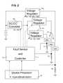
- FIG. 2is a schematic diagram illustrating further aspects of the invention as discussed below.
- FIG. 3is a block diagram illustrating an alternative embodiment that is similar to FIG. 2 but has voltage regulators with current-sense and/or current-limiting circuits included therein.
- FIG. 1illustrates an exemplary battery operated system 10 implementing a fault controller 12 according to an aspect of the invention.
- the systemis exemplified in a cellular telephone as shown by the illustration of RF and audio CODEC functions, but can also be embodied in other devices that have a plurality of loads.
- the loadsare selectively activated, e.g., being switchably coupled to the power supply or alternatively being directly coupled to the power supply but switchable between more or less active versus quiescent states of operation. Subsets comprising one or more of the loads may be drawing current in a given operational scenario, whereas others of the loads may be inactive or decoupled from the power supply.
- the apparatuscomprises a power fault controller 12 that can comprise a processor or a series of gates, arranged to assess operational status and to report to a system controller 22 .
- the power fault controller 12can be coupled to a temperature monitor 15 a for developing a fault indication signal, and a thermal shutdown element 15 b via suitable signal lines 71 a , 17 b , respectively.
- the fault controlleris coupled to a variety of elements 16 a - 16 e , that sink or source current in different operational states.
- the power managed deviceincludes a program for operating the system controller 22 and input/output devices including manually operable switch inputs 16 a and indicators such as LEDs coupled to drivers 16 b are more or less directly coupled to the controller 22 .
- Switching between operational statesis partly a matter of a user's operation of a keyboard (KBD) and/or accessory switches 16 a , and also is determined as a programmed matter by the system controller 22 in conjunction with inputs from the user and from signals received, e.g., from RF/Codec element 16 e.
- Some of the load devicesare involved in primary functions of the device, such as communications in a cellular telephone embodiment requiring user operated switch selections, local display of information under control of the system controller 22 , and remote signaling over the RF/Codec element. These functions can be accorded a higher priority than other functions, particularly in a low battery condition as determined by the battery charger element 16 c and reported to the fault controller 12 .
- the fault controller 12either independently or in conjunction with signaling between the fault controller 12 and the system controller 22 , determines the operational state and determine whether one or more loads will be decoupled so as to conserve battery power, to reduce the rate of discharge or otherwise to control power consumption.
- FIG. 2shows a number of loads that have separate or shared regulators that are controlled by the fault controller for regulating the current from the basic power supply, namely a battery, to the respective loads.
- the respective load functions 24could be data storage and retrieval functions, clock and alarm functions, camera functions such as display, record picture, flash, audio record or playback, etc.
- one or more of the functionsadvantageously can be disabled in favor of another function, either by programmed decision or by user selection among alternatives offered by a programmed process associated with the controller 22 .
- Battery operated system 10 in FIG. 1comprises a power management device 14 having at least one fault status detector 15 a - 15 b and a plurality of power loads 16 a - 16 e .
- fault status detector 15examples include an on-chip temperature monitor 15 a and a thermal shutdown circuit 15 b .
- power loads 16 a - einclude supply regulators, battery chargers, accessory switch control, one or more switched mode power supplies (SMPS), LED drivers, etc.
- Additional load functionsthat might advantageously be of limited priority can be, e.g., vibrator drivers, ringer drivers, camera modules, video processors, Bluetooth modules, MP3 audio players, etc.
- a control and/or status signaling line 17 a - 17 belectrically couples fault controller 12 to fault status detector 15 a - 15 b , by which a fault status signal is sent from fault status detector 15 to fault controller 12 .
- a plurality of input load lines 18 a - 18 eelectrically couple fault controller 12 to each of plurality of power load functions 16 a - 16 e .
- Fault controller 12accepts inputs from power load functions 16 ( a - e ) by means of input load line 18 ( a - e ).
- monitoring circuits associated with power load functions 16send an indication to fault controller 12 through input load lines 18 ( a - e ).
- Fault controller 12may also monitor each fault status detector 15 by polling for status.
- the monitoring circuitscan comprise over-current and/or under-voltage threshold detectors (not shown) or similar devices for generating a signal under predetermined conditions related to current, voltage, temperature, elapsed time or other parameters.
- on-chip temperature monitor 15 ( a )transmits a temperature signal via fault status line 17 a to fault controller 12 , by which fault controller 12 can monitor the on-chip temperature as an early warning indicator.
- a rise in temperature on the device at a point adjacent to a power sourcing elementis an indication of increased average current draw.
- Thermal shutdown circuit 15 btransmits a thermal shutdown signal via fault status line 17 b to fault controller 12 , by which fault controller 12 can be alerted of a potentially damaging short or other failure within system 10 .
- Fault controller 12can be comprised of a controller or a set of gates that are arranged to react to the severity of a fault by evaluating the fault indicators from plural load elements. The fault controller 12 also can react to other factors, including which function appears to be the source of the error, which functions are presently active, and whether the offending and active functions are critical or non-critical functions in view of the operative state of the battery operated system 10 .
- the fault controllercan signal the system controller 22 , which can be programmed to warn the user and/or to decline to initiate non-critical functions in predetermined operational states wherein a critical function may be adversely affected.
- the fault controller 12can react to the severity of the fault, for example reacting to a potential short circuit current fault by decoupling an active load.
- the fault controller 12can also be arranged to revise operations by suspending a function temporarily while another function proceeds.
- the fault controller 12can determine a course of action either independently or together with signaling between the fault controller 12 and the system controller 22 as well as a user. User input can be prompted on the display drivers or by audio signaling and received over the accessory switch and/or KBD inputs.
- voltage regulators 16 e for the various load functionscan be more or less proximal to a battery power source or to the SMPS DC/DC inverter 16 d .
- the current draw of loadscan be determined by voltage threshold detection using current sense resistors R 1 -R 3 or, although not shown in FIG. 2 , using current replica repeaters built into the regulators themselves.
- the potential actionsmay include (without limitation) shutting down an offending load function 24 , shutting down a regulator providing current to a function or controlling the regulator to decrease the current available, generating an interrupt or setting an appropriate status indication in a status register to provide information to controller 22 (which controller can be programmed to reconfigure permitted operations and/or power supply allocation.
- the fault controllercan contain a nonvolatile status register containing plural bits (3 bits being shown to represent eight different values), or that power to the status register be maintained at least in the event of a dire condition such as high temperature cutoff (e.g., above 155 degrees F.) associated with one of the respective load functions 24 .
- a dire conditionsuch as high temperature cutoff (e.g., above 155 degrees F.) associated with one of the respective load functions 24 .
- high temperature cutoffe.g., above 155 degrees F.
- the severity of the faultcan also be gauged with the assistance of on-chip temperature monitor 15 a if necessary (i.e. the chip is rapidly heating due to a fault somewhere in the system).
- a portable deviceis made fault tolerant, particularly in the event of a high current draw by a particular load device.
- a single regulatormight readily be provided with a switched output to snub high current conditions
- the point of the inventionis to provide a way to preprogram a considered response to a fault condition, including considerations for dealing most appropriately with the fault condition in view of operational status and the nature of the fault.
- FIG. 3An alternative embodiment of the invention is shown in FIG. 3 .
- This embodimentresembles FIG. 2 but as shown, the voltage regulators 16 e are provided with internal current limit circuits.
- the fault sensor and controller 12 as described aboveis arranged to receive current indication signals from the voltage regulators, for example a state signal from respective voltage regulators having at least two and potentially more different signal levels, from which the state of the particular regulator 16 e can be surmised.
- the fault sensorhas outputs coupled back to control the regulators 16 e , as shown by the broken line in FIG. 3 .
- This controlpreferably includes an ability to disable the output of the voltage regulator.
- the fault sensoralso can be arranged to dictate one or more current threshold levels to the regulators 16 e , e.g., with respect to instantaneous or average current draw.
- one way to disable the regulator 16 emay be to set a very low current output threshold during an operational state wherein the respective load 24 would draw current if available.
- the fault sensor and controllercan obtain control input information and generate control output signals that enable a relatively sophisticate set of operational states and current thresholds.
Landscapes
- Engineering & Computer Science (AREA)
- Power Engineering (AREA)
- Telephone Function (AREA)
- Charge And Discharge Circuits For Batteries Or The Like (AREA)
Abstract
Description
Claims (13)
Priority Applications (1)
| Application Number | Priority Date | Filing Date | Title |
|---|---|---|---|
| US11/380,943US7460929B2 (en) | 2006-05-01 | 2006-05-01 | Integrated current fault controller |
Applications Claiming Priority (1)
| Application Number | Priority Date | Filing Date | Title |
|---|---|---|---|
| US11/380,943US7460929B2 (en) | 2006-05-01 | 2006-05-01 | Integrated current fault controller |
Publications (2)
| Publication Number | Publication Date |
|---|---|
| US20070255460A1 US20070255460A1 (en) | 2007-11-01 |
| US7460929B2true US7460929B2 (en) | 2008-12-02 |
Family
ID=38649375
Family Applications (1)
| Application Number | Title | Priority Date | Filing Date |
|---|---|---|---|
| US11/380,943Active2026-06-11US7460929B2 (en) | 2006-05-01 | 2006-05-01 | Integrated current fault controller |
Country Status (1)
| Country | Link |
|---|---|
| US (1) | US7460929B2 (en) |
Cited By (3)
| Publication number | Priority date | Publication date | Assignee | Title |
|---|---|---|---|---|
| US8151122B1 (en)* | 2007-07-05 | 2012-04-03 | Hewlett-Packard Development Company, L.P. | Power budget managing method and system |
| US20130282317A1 (en)* | 2012-04-23 | 2013-10-24 | Lsis Co., Ltd | Method of controlling fault current in system for monitoring and controlling power system |
| US9911249B2 (en)* | 2012-09-20 | 2018-03-06 | GM Global Technology Operations LLC | Fail operational power system diagnostics |
Families Citing this family (27)
| Publication number | Priority date | Publication date | Assignee | Title |
|---|---|---|---|---|
| CA2508800A1 (en) | 2002-12-11 | 2004-06-24 | Proteus Biomedical, Inc. | Method and system for monitoring and treating hemodynamic parameters |
| US7444192B2 (en) | 2004-10-26 | 2008-10-28 | Aerovironment, Inc. | Reactive replenishable device management |
| US20060089844A1 (en)* | 2004-10-26 | 2006-04-27 | Aerovironment, Inc., A California Corporation | Dynamic replenisher management |
| EP1871470A4 (en) | 2005-03-31 | 2011-06-01 | Proteus Biomedical Inc | Automated optimization of multi-electrode pacing for cardiac resynchronization |
| KR100801992B1 (en)* | 2006-06-30 | 2008-02-12 | 주식회사 넥스지 | Automatic power controller by determining abnormal status of external equipment |
| DE102007021035A1 (en)* | 2007-05-04 | 2008-11-13 | Siemens Ag | Image processing, image visualization and image archiving system for the contra-merging and visualization of coregistered image data |
| US20090240863A1 (en)* | 2007-10-23 | 2009-09-24 | Psion Teklogix Inc. | Distributed power regulation |
| US8473069B2 (en) | 2008-02-28 | 2013-06-25 | Proteus Digital Health, Inc. | Integrated circuit implementation and fault control system, device, and method |
| US8098469B2 (en)* | 2008-04-16 | 2012-01-17 | O2Micro Inc. | Electricity delivery system |
| US20090287266A1 (en)* | 2008-05-13 | 2009-11-19 | Mark Zdeblick | High-voltage tolerant multiplex multi-electrode stimulation systems and methods for using the same |
| EP2149957B1 (en)* | 2008-07-30 | 2017-06-14 | Harman Becker Automotive Systems GmbH | Priority based power distribution arrangement |
| WO2010126503A1 (en) | 2009-04-29 | 2010-11-04 | Proteus Biomedical, Inc. | Methods and apparatus for leads for implantable devices |
| WO2011011736A2 (en) | 2009-07-23 | 2011-01-27 | Proteus Biomedical, Inc. | Solid-state thin film capacitor |
| WO2011130672A1 (en) | 2010-04-15 | 2011-10-20 | Jim Hunter | Monitoring system for proactive service of devices |
| US20110278921A1 (en)* | 2010-05-11 | 2011-11-17 | Erik Jon Fretheim | Adaptive Power Bus |
| US8718770B2 (en) | 2010-10-21 | 2014-05-06 | Medtronic, Inc. | Capture threshold measurement for selection of pacing vector |
| US8355784B2 (en) | 2011-05-13 | 2013-01-15 | Medtronic, Inc. | Dynamic representation of multipolar leads in a programmer interface |
| US9883257B2 (en)* | 2013-08-14 | 2018-01-30 | Atmel Corporation | Smart grid appliance control |
| EP2988393A1 (en)* | 2014-08-19 | 2016-02-24 | International Currency Technologies Corporation | Automatic vending machine management control box |
| US10089168B2 (en) | 2014-11-14 | 2018-10-02 | T-Mobile Usa, Inc. | Self-healing charging device |
| US10031826B2 (en) | 2014-11-14 | 2018-07-24 | T-Mobile Usa, Inc. | Self-healing charging device |
| US11303111B2 (en) | 2018-12-26 | 2022-04-12 | Eaton Intelligent Power Limited | Configurable modular hazardous location compliant circuit protection devices, systems and methods |
| US11615925B2 (en) | 2018-12-26 | 2023-03-28 | Eaton Intelligent Power Limited | Hazardous location compliant circuit protection devices having enhanced safety intelligence, systems and methods |
| US11270854B2 (en)* | 2018-12-26 | 2022-03-08 | Eaton Intelligent Power Limited | Circuit protection devices, systems and methods for explosive environment compliance |
| US11239652B2 (en)* | 2018-12-26 | 2022-02-01 | Eaton Intelligent Power Limited | Compliant, hazardous environment circuit protection devices, systems and methods |
| US10822107B1 (en)* | 2019-04-19 | 2020-11-03 | The Boeing Company | Integration of vehicle management system and power distribution control |
| CN116094085A (en)* | 2022-11-15 | 2023-05-09 | 福建星云电子股份有限公司 | Energy storage battery protection method for micro-grid energy management system |
Citations (7)
| Publication number | Priority date | Publication date | Assignee | Title |
|---|---|---|---|---|
| US4675770A (en)* | 1985-01-30 | 1987-06-23 | Telefonaktiebolaget L. M. Ericsson | Multiple voltage regulator integrated circuit having control circuits for selectively disabling a voltage regulator in an over-current condition |
| US6008971A (en)* | 1998-03-23 | 1999-12-28 | Electric Boat Corporation | Fault protection arrangement for electric power distribution systems |
| US6127882A (en)* | 1999-02-23 | 2000-10-03 | Maxim Integrated Products, Inc. | Current monitors with independently adjustable dual level current thresholds |
| US6788035B2 (en)* | 2001-06-12 | 2004-09-07 | Primarion, Inc. | Serial bus control method and apparatus for a microelectronic power regulation system |
| US20050289373A1 (en)* | 2002-11-13 | 2005-12-29 | Power-One, Inc. | Method and system for controlling and monitoring an array of point-of-load regulators |
| US20060287838A1 (en)* | 2005-06-17 | 2006-12-21 | Hamilton Sundstrand Corporation | Protection system for an electrical power generator |
| US7236338B2 (en)* | 2003-09-16 | 2007-06-26 | The Boeing Company | System and method for remotely detecting and locating faults in a power system |
- 2006
- 2006-05-01USUS11/380,943patent/US7460929B2/enactiveActive
Patent Citations (7)
| Publication number | Priority date | Publication date | Assignee | Title |
|---|---|---|---|---|
| US4675770A (en)* | 1985-01-30 | 1987-06-23 | Telefonaktiebolaget L. M. Ericsson | Multiple voltage regulator integrated circuit having control circuits for selectively disabling a voltage regulator in an over-current condition |
| US6008971A (en)* | 1998-03-23 | 1999-12-28 | Electric Boat Corporation | Fault protection arrangement for electric power distribution systems |
| US6127882A (en)* | 1999-02-23 | 2000-10-03 | Maxim Integrated Products, Inc. | Current monitors with independently adjustable dual level current thresholds |
| US6788035B2 (en)* | 2001-06-12 | 2004-09-07 | Primarion, Inc. | Serial bus control method and apparatus for a microelectronic power regulation system |
| US20050289373A1 (en)* | 2002-11-13 | 2005-12-29 | Power-One, Inc. | Method and system for controlling and monitoring an array of point-of-load regulators |
| US7236338B2 (en)* | 2003-09-16 | 2007-06-26 | The Boeing Company | System and method for remotely detecting and locating faults in a power system |
| US20060287838A1 (en)* | 2005-06-17 | 2006-12-21 | Hamilton Sundstrand Corporation | Protection system for an electrical power generator |
Cited By (3)
| Publication number | Priority date | Publication date | Assignee | Title |
|---|---|---|---|---|
| US8151122B1 (en)* | 2007-07-05 | 2012-04-03 | Hewlett-Packard Development Company, L.P. | Power budget managing method and system |
| US20130282317A1 (en)* | 2012-04-23 | 2013-10-24 | Lsis Co., Ltd | Method of controlling fault current in system for monitoring and controlling power system |
| US9911249B2 (en)* | 2012-09-20 | 2018-03-06 | GM Global Technology Operations LLC | Fail operational power system diagnostics |
Also Published As
| Publication number | Publication date |
|---|---|
| US20070255460A1 (en) | 2007-11-01 |
Similar Documents
| Publication | Publication Date | Title |
|---|---|---|
| US7460929B2 (en) | Integrated current fault controller | |
| EP0736828A2 (en) | Battery driven electronic apparatus and method of controlling power supply in the apparatus | |
| US8278781B2 (en) | Discharger and discharger control method | |
| JP3749538B2 (en) | Battery unit and device using battery unit | |
| US6879132B2 (en) | Switching power supply unit | |
| US6208117B1 (en) | Battery pack and electronic apparatus using the same | |
| US7688025B2 (en) | Electronic device, battery pack, power-supply controlling method for electronic device, program for controlling power supply for electronic device | |
| JP4401954B2 (en) | Power supply control device and power supply control program | |
| JP3859608B2 (en) | Battery pack, electronic device, remaining battery level prediction system, and semiconductor device | |
| CN102741776A (en) | Circuit and method for an uninterruptable power supply of electronic modules | |
| US11271256B2 (en) | Externally mode-switchable battery pack and method for externally switching mode of battery pack | |
| JP2022519073A (en) | Battery management system, battery management method, battery pack and electric vehicle | |
| JP2013046454A (en) | Dc power supply | |
| US7360107B2 (en) | Method of controlling power within a disk array apparatus | |
| US7449864B2 (en) | Apparatus and method for controlling battery discharge between internal battery and external battery | |
| JP2005253273A (en) | Dc power supply system | |
| TW201011513A (en) | Multi-output voltage battery module and electronic device using the same | |
| JP5067816B2 (en) | Portable electronic device and control method thereof | |
| JP2018023267A (en) | Electronic device with backup power supply and method for charging and discharging backup power supply | |
| JP2002300732A (en) | Secondary battery device | |
| TWI415363B (en) | Battery management circuit, battery module and battery management method | |
| KR100384267B1 (en) | An Accident Reporting System of an Un-interrupt Power Supply and It's reporting Method | |
| JPH08336242A (en) | Electronic equipment | |
| JP4051708B2 (en) | Battery fault detector | |
| JP4097422B2 (en) | Battery deep discharge detection method and deep discharge detection device |
Legal Events
| Date | Code | Title | Description |
|---|---|---|---|
| AS | Assignment | Owner name:AGERE SYSTEMS INC., PENNSYLVANIA Free format text:ASSIGNMENT OF ASSIGNORS INTEREST;ASSIGNOR:LOPATA, DOUGLAS D.;REEL/FRAME:017552/0579 Effective date:20060501 | |
| STCF | Information on status: patent grant | Free format text:PATENTED CASE | |
| FEPP | Fee payment procedure | Free format text:PAYOR NUMBER ASSIGNED (ORIGINAL EVENT CODE: ASPN); ENTITY STATUS OF PATENT OWNER: LARGE ENTITY | |
| FPAY | Fee payment | Year of fee payment:4 | |
| AS | Assignment | Owner name:DEUTSCHE BANK AG NEW YORK BRANCH, AS COLLATERAL AG Free format text:PATENT SECURITY AGREEMENT;ASSIGNORS:LSI CORPORATION;AGERE SYSTEMS LLC;REEL/FRAME:032856/0031 Effective date:20140506 | |
| AS | Assignment | Owner name:AVAGO TECHNOLOGIES GENERAL IP (SINGAPORE) PTE. LTD Free format text:ASSIGNMENT OF ASSIGNORS INTEREST;ASSIGNOR:AGERE SYSTEMS LLC;REEL/FRAME:035365/0634 Effective date:20140804 | |
| AS | Assignment | Owner name:LSI CORPORATION, CALIFORNIA Free format text:TERMINATION AND RELEASE OF SECURITY INTEREST IN PATENT RIGHTS (RELEASES RF 032856-0031);ASSIGNOR:DEUTSCHE BANK AG NEW YORK BRANCH, AS COLLATERAL AGENT;REEL/FRAME:037684/0039 Effective date:20160201 Owner name:AGERE SYSTEMS LLC, PENNSYLVANIA Free format text:TERMINATION AND RELEASE OF SECURITY INTEREST IN PATENT RIGHTS (RELEASES RF 032856-0031);ASSIGNOR:DEUTSCHE BANK AG NEW YORK BRANCH, AS COLLATERAL AGENT;REEL/FRAME:037684/0039 Effective date:20160201 | |
| AS | Assignment | Owner name:BANK OF AMERICA, N.A., AS COLLATERAL AGENT, NORTH CAROLINA Free format text:PATENT SECURITY AGREEMENT;ASSIGNOR:AVAGO TECHNOLOGIES GENERAL IP (SINGAPORE) PTE. LTD.;REEL/FRAME:037808/0001 Effective date:20160201 Owner name:BANK OF AMERICA, N.A., AS COLLATERAL AGENT, NORTH Free format text:PATENT SECURITY AGREEMENT;ASSIGNOR:AVAGO TECHNOLOGIES GENERAL IP (SINGAPORE) PTE. LTD.;REEL/FRAME:037808/0001 Effective date:20160201 | |
| FPAY | Fee payment | Year of fee payment:8 | |
| AS | Assignment | Owner name:AVAGO TECHNOLOGIES GENERAL IP (SINGAPORE) PTE. LTD., SINGAPORE Free format text:TERMINATION AND RELEASE OF SECURITY INTEREST IN PATENTS;ASSIGNOR:BANK OF AMERICA, N.A., AS COLLATERAL AGENT;REEL/FRAME:041710/0001 Effective date:20170119 Owner name:AVAGO TECHNOLOGIES GENERAL IP (SINGAPORE) PTE. LTD Free format text:TERMINATION AND RELEASE OF SECURITY INTEREST IN PATENTS;ASSIGNOR:BANK OF AMERICA, N.A., AS COLLATERAL AGENT;REEL/FRAME:041710/0001 Effective date:20170119 | |
| AS | Assignment | Owner name:AVAGO TECHNOLOGIES INTERNATIONAL SALES PTE. LIMITE Free format text:MERGER;ASSIGNOR:AVAGO TECHNOLOGIES GENERAL IP (SINGAPORE) PTE. LTD.;REEL/FRAME:047195/0658 Effective date:20180509 | |
| AS | Assignment | Owner name:AVAGO TECHNOLOGIES INTERNATIONAL SALES PTE. LIMITE Free format text:CORRECTIVE ASSIGNMENT TO CORRECT THE EFFECTIVE DATE OF MERGER PREVIOUSLY RECORDED ON REEL 047195 FRAME 0658. ASSIGNOR(S) HEREBY CONFIRMS THE THE EFFECTIVE DATE IS 09/05/2018;ASSIGNOR:AVAGO TECHNOLOGIES GENERAL IP (SINGAPORE) PTE. LTD.;REEL/FRAME:047357/0302 Effective date:20180905 | |
| AS | Assignment | Owner name:AVAGO TECHNOLOGIES INTERNATIONAL SALES PTE. LIMITE Free format text:CORRECTIVE ASSIGNMENT TO CORRECT THE ERROR IN RECORDING THE MERGER PREVIOUSLY RECORDED AT REEL: 047357 FRAME: 0302. ASSIGNOR(S) HEREBY CONFIRMS THE ASSIGNMENT;ASSIGNOR:AVAGO TECHNOLOGIES GENERAL IP (SINGAPORE) PTE. LTD.;REEL/FRAME:048674/0834 Effective date:20180905 | |
| MAFP | Maintenance fee payment | Free format text:PAYMENT OF MAINTENANCE FEE, 12TH YEAR, LARGE ENTITY (ORIGINAL EVENT CODE: M1553); ENTITY STATUS OF PATENT OWNER: LARGE ENTITY Year of fee payment:12 |