US7460758B2 - Fiber management system - Google Patents
Fiber management systemDownload PDFInfo
- Publication number
- US7460758B2 US7460758B2US11/230,791US23079105AUS7460758B2US 7460758 B2US7460758 B2US 7460758B2US 23079105 AUS23079105 AUS 23079105AUS 7460758 B2US7460758 B2US 7460758B2
- Authority
- US
- United States
- Prior art keywords
- tray
- module
- chassis
- axis
- trays
- Prior art date
- Legal status (The legal status is an assumption and is not a legal conclusion. Google has not performed a legal analysis and makes no representation as to the accuracy of the status listed.)
- Expired - Lifetime, expires
Links
Images


Classifications
- G—PHYSICS
- G02—OPTICS
- G02B—OPTICAL ELEMENTS, SYSTEMS OR APPARATUS
- G02B6/00—Light guides; Structural details of arrangements comprising light guides and other optical elements, e.g. couplings
- G02B6/44—Mechanical structures for providing tensile strength and external protection for fibres, e.g. optical transmission cables
- G02B6/4439—Auxiliary devices
- G02B6/444—Systems or boxes with surplus lengths
- G02B6/4453—Cassettes
- G02B6/4455—Cassettes characterised by the way of extraction or insertion of the cassette in the distribution frame, e.g. pivoting, sliding, rotating or gliding
- G—PHYSICS
- G02—OPTICS
- G02B—OPTICAL ELEMENTS, SYSTEMS OR APPARATUS
- G02B6/00—Light guides; Structural details of arrangements comprising light guides and other optical elements, e.g. couplings
- G02B6/44—Mechanical structures for providing tensile strength and external protection for fibres, e.g. optical transmission cables
- G02B6/4439—Auxiliary devices
- G02B6/444—Systems or boxes with surplus lengths
- G02B6/4452—Distribution frames
- G02B6/44524—Distribution frames with frame parts or auxiliary devices mounted on the frame and collectively not covering a whole width of the frame or rack
- G—PHYSICS
- G02—OPTICS
- G02B—OPTICAL ELEMENTS, SYSTEMS OR APPARATUS
- G02B6/00—Light guides; Structural details of arrangements comprising light guides and other optical elements, e.g. couplings
- G02B6/44—Mechanical structures for providing tensile strength and external protection for fibres, e.g. optical transmission cables
- G02B6/4439—Auxiliary devices
- G02B6/444—Systems or boxes with surplus lengths
- G02B6/4452—Distribution frames
- G02B6/44526—Panels or rackmounts covering a whole width of the frame or rack
- G—PHYSICS
- G02—OPTICS
- G02B—OPTICAL ELEMENTS, SYSTEMS OR APPARATUS
- G02B6/00—Light guides; Structural details of arrangements comprising light guides and other optical elements, e.g. couplings
- G02B6/44—Mechanical structures for providing tensile strength and external protection for fibres, e.g. optical transmission cables
- G02B6/4439—Auxiliary devices
- G02B6/444—Systems or boxes with surplus lengths
- G02B6/44528—Patch-cords; Connector arrangements in the system or in the box
Definitions
- the following disclosurerelates generally to systems for managing and organizing fibers, such as optical fibers.
- Optical fiberscan be used to transmit large volumes of data and voice signals over relatively long distances, with little or no signal degradation. For this reason, optical fibers have become widely used in the telecommunication field. As the use of optical fibers has increased, new systems have been developed for managing and organizing larger numbers of optical fibers.
- typical optical fiber management systemsinclude cable management structures for storing the fibers or connecting the fibers to one or more other fibers and/or fiber optic devices, such as attenuators, connectors, switches, multiplexers, splitters/combiners, or splices.
- fiber management systemsare often mounted to a wall or to an equipment rack.
- One or more rack unitsare generally mounted to the wall or rack, and include one or more drawers or trays having the cable management structure for organizing the fibers.
- a fiber management apparatusincludes a module having at least two trays. At least an upper one of the trays is pivotable relative to at least one base tray, so that the upper tray can be lifted to allow access to fibers managed by the base tray.
- the upper trayis also slidable outward relative to the base tray to provide additional clearance between the upper tray and the front of the chassis, so that the upper tray can be lifted, even when, for example, fibers protrude from the front face of an overhead piece of equipment.
- a fiber management apparatusin another aspect, includes a chassis, and a module coupled to the chassis at a module hinge.
- the moduleis pivotable through an angle greater than 90 degrees relative to the chassis, to provide better access to fibers managed by the module.
- a kit for mounting a chassis on a rackincludes at least two sets of brackets, each set of brackets being of a different size, such that the kit can be used to mount the chassis to racks of various different widths.
- the chassismay also include adjustable mounting features, to allow the chassis to be coupled to a rack in at least two different front-to-back positions.
- a method of managing fibersincludes pulling a module having multiple trays out of a chassis. A first exposed one of the trays is then pulled outward, away from a front surface of the chassis, and is lifted to expose a second one of the trays.
- FIG. 1is perspective view of one exemplary fiber management apparatus, including a rack with a plurality of rack units mounted thereto.
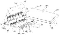
- FIG. 2is a perspective view of the rack unit of FIG. 1 .
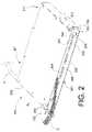
- FIG. 3is a plan view of the rack unit of FIG. 1 , showing a module pivoted out in an extended position.
- FIG. 4is a perspective view of the rack unit of FIG. 1 , with the module pivoted out in an extended position and a first tray in a raised position.
- FIG. 5is a perspective view of the rack unit of FIG. 1 , with the module pivoted out in an extended position, and the first tray in a raised position and slid out relative to a second tray.
- FIG. 6is an enlarged detail view of the right side of the rack unit of FIG. 1 , showing several brackets usable with the rack unit.
- FIG. 7is a flow chart showing one exemplary method of configuring a fiber management apparatus.
- This disclosureis directed to apparatuses for managing fibers, kits for mounting fiber management apparatuses, and methods of configuring fiber management apparatuses.
- the apparatusesare described in the context of a rack-mounted system for managing optical fibers. However, the apparatuses described herein may be used in other environments and are applicable to other contexts. For example, the apparatuses need not be mounted to a rack, and may, for example, be wall-mounted, free standing, or the like. In addition, the apparatuses may be used to manage fibers other than optical fibers, such as wire and the like.
- FIG. 1illustrates a conventional free standing rack 100 , on which are mounted a plurality of rack units 101 .
- the rack units 101are attached via brackets 102 to mounting holes 103 in the vertical sides of the rack 100 .
- the rack 100 shown in FIG. 1is typical of those used by, for example, telecommunications companies to organize, route, distribute, hold, or otherwise manage incoming and outgoing optical fibers in a telecommunications facility. While the optical fibers have been omitted from all of the drawings except FIGS. 2 and 3 (which are discussed in detail below), a brief description of the optical fiber routes through the fiber management system will be useful for clarity.
- one or more outside fiber cablesenter the telecommunications facility and are fed to one or more of the rack units 101 held by the rack 100 . As described in more detail with reference to FIGS.
- the incoming fiber cablesinclude a plurality of bundled individual optical fibers, which are separated and routed to one or more other optical fibers or optical devices in the rack units 101 .
- Outgoing fibersexit the rack units 101 and are routed to other equipment inside or outside the telecommunications facility.
- whole roomsmight be filled with racks similar to the one shown in FIG. 1 .
- rack 100is shown in FIG. 1 with nine identical rack units 101 mounted thereon, any number of rack units can be mounted to the rack 100 .
- size and shape of the rack units 101 coupled to the rackmay vary depending on the particular needs of the user. For example, the width, depth, and thickness of the rack units may differ, the overall shape of the rack units may vary, the specific components of the rack units may vary, and the like.
- FIGS. 2-5show a representative rack unit 101 in more detail.
- the rack unit 101includes a housing or chassis 200 , and a module 201 coupled to the chassis 200 for managing a plurality of fibers.
- the module 201is coupled to the chassis 200 by a module hinge 202 , which defines a module axis A m about which the module 201 is pivotable relative to the chassis 200 .
- the module 201is pivotable between a first position (shown in FIG. 2 ), in which the module 201 is at least partially enclosed by the chassis 200 , and a second position (shown in FIG. 3 ), in which the module 201 is substantially extended from the chassis to allow a user to access the fibers managed by the module 201 .
- a first positionshown in FIG. 2
- FIG. 3shows a second position
- the module 201when the module 201 is in the first, retracted position, the module 201 is held in place by a latch 203 .
- the useropens the latch 203 and pulls the module 201 out to the extended position shown in FIG. 3 .
- chassis 200is shown as being a generally rectangular enclosure, having substantially planar top, bottom, side, and back surfaces, numerous other chassis configurations are also possible, as long as the chassis is capable of coupling the module to the rack and supporting the module.
- the chassiscould be an open framework with no sides at all, or the chassis could simply include a bracket for securing the hinge 202 to a rack with no framework or sides at all.
- module 201is shown and described as being coupled to the chassis 200 by module hinge 202 , the module 201 might be coupled to the chassis 200 in numerous other configurations.
- the module 201could be coupled to the chassis 200 in a drawer configuration, with the module 201 being slidable in and out of the chassis 200 .
- the chassiscould be omitted entirely, with the module 201 being connectable directly to the rack 100 .
- FIG. 3shows module 201 being pivotable through an angle ( ⁇ ).
- angle ( ⁇ )is greater than 90 degrees relative to the chassis 200 to provide improved access to the managed fibers and to provide additional clearance between the module 201 and the front of the chassis 200 .
- the angle ( ⁇ )is between about 90 and about 110 degrees. In another implementation, the angle ( ⁇ ) is between about 100 and about 110 degrees.
- FIGS. 2 , 4 , and 5show the module 201 having a plurality of stacked trays.
- there are two stacked traysincluding at least a first or upper tray 204 and a second or base tray 205 .
- the base tray 205is coupled to the chassis 200 via the module hinge 202 to enable the module 201 , including the stacked tray arrangement, to move between the enclosed and extended positions.
- the upper tray 204is moveable relative to the base tray 205 .
- the upper tray 204is pivotally coupled to the base tray 205 at a tray hinge 206 .
- the tray hinge 206defines a tray axis A t about which the upper tray 204 is pivotable relative to base tray 205 .
- the base tray 205is coupled directly to the module hinge 202 , and is fixed against rotation about the tray axis A t .
- the base tray 205may be configured to pivot about the tray axis A t by, for example, coupling the base tray 205 to the module hinge 202 via an additional mounting member (not shown).
- tray axis A tis not parallel to the module axis A m , and in another implementation, the tray axis A t is substantially perpendicular to the module axis A m . Also, while the plurality of trays is shown and described as a pair of trays for clarity, any number of additional pivotable trays may also be provided. These additional trays may be coupled in substantially the same manner as the upper tray described herein, or in other moveable arrangements with respect to the base tray.
- the upper tray 204is pivotable between a lowered position (shown in FIGS. 2 and 3 ) for storage in the chassis 200 , and a raised position (shown in FIG. 4 ) to provide access to the fibers managed by the base tray 205 .
- a lowered positionshown in FIGS. 2 and 3
- a raised positionshown in FIG. 4
- the upper tray 204is supported by the tray hinge 206 along one edge and, as best shown in FIG. 4 , by a plurality of rest tabs 400 and a vertical edge 401 formed about the perimeter of the base tray 205 .
- the upper tray 204When the upper tray is in the raised position, the upper tray 204 may be past its tipping point. In that case, stop tabs 207 and 208 (best shown in FIG. 2 ) protruding from the upper and base trays, respectively, abut the front surfaces 209 and 210 of the lower and upper trays, respectively, to prevent the upper tray 204 from pivoting beyond a desired point.
- the upper tray 204is allowed to pivot through an angle of at least about 90 degrees relative to the base tray 205 . In another implementation, the upper tray 204 is pivotable through an angle of between about 90 degrees and about 100 degrees.
- the upper tray 204may also be pivotable by less than 90 degrees relative to the base tray, in which case, the upper tray may be held in the raised position by suitable known holding means, such as a prop arm, a detent mechanism, a magnet, a ratcheting mechanism, a latch, and the like.
- suitable known holding meanssuch as a prop arm, a detent mechanism, a magnet, a ratcheting mechanism, a latch, and the like.
- FIG. 3shows an incoming plant fiber-cable f 1 comprising a well protected bundle of individual fibers (usually 12 or 24 fibers) entering the rack unit 101 through openings 211 in the back of the chassis 200 .
- the individual fibersare then separated and routed through one or more sections of conventional bend-limiting tubing f 2 .
- the sections of bend-limiting tubing f 2protect the fibers and prevent them from being bent beyond an acceptable radius, since that could cause transmission losses and/or breakage of the fibers.
- the sections of bend-limiting tubing f 2are then looped around spools or reels 300 in the trays 204 and 205 to provide the desired amount of slack (typically ⁇ 1.5 meters).
- the individual fibersthen emerge from the bend-limiting tubing and are connected to one or more outgoing fibers (f 3 ) or optical devices (not shown) via a plurality of fiber connectors 301 .
- the individual outgoing fibers (f 3 )exit the rack unit 101 through an opening in the front of the module 201 , and are held in place at the front corner of the rack unit 101 by a tether 302 for convenient routing to other locations in the user's facility.
- each incoming fiber cablemay include more than twelve individual optical fibers (typically, twenty-four).
- the module 201 illustrated in the figuresis designed to manage forty-eight fiber connections. If filled to capacity, the module 201 might have two incoming fiber cables, each holding twenty-four individual incoming optical fibers. The individual optical fibers would then be routed through sections of bend-limiting tubing. Typically, four sections of bend-limiting tubing would be used, with two sections of twelve fibers each being managed by each of trays 204 and 205 , in the same manner as the fibers shown in FIG. 3 .
- the fiber connectors 301are mounted along the length of each of trays 204 and 205 , and are held in place by fiber mounts 303 .
- the connectors 301are patch connectors, with two groups of twelve connectors being positioned along the length of each tray.
- any suitable type and number of connectors and/or optical devicescould be used in addition to or in place of the patch connectors, depending on the needs of the user.
- Other suitable types of connectors and optical devicesinclude splices, attenuators, connectors, switches, multiplexers, splitters/combiners, and the like.
- the base tray 205might be provided with one or more splice cassettes, while the upper tray 204 is provided with twenty-four patch connectors, or both the upper and base trays 204 and 205 might be provided with splice cassettes.
- the rack unit 101is capable of managing forty-eight incoming and forty-eight outgoing fibers, in a rack unit having a thickness (t) of two inches or less, while providing easy, unobstructed access to the managed fibers.
- the actual thickness (t) of the rack unit 101is between about 1.6 and about 1.9 inches. More specifically, the thickness can be between about 1.7 and 1.8 inches.
- This configurationalso allows the outgoing fibers to exit the rack unit 101 from the front face of the rack unit 101 for convenient routing to other equipment or the like.
- this configurationcould be used to manage less than forty-eight incoming and forty-eight outgoing fibers.
- the rack unitsmay be adapted to manage more than forty-eight incoming and forty-eight outgoing fibers by, for example, changing the placement of the fiber connectors on the trays, staggering the fiber connectors on the trays, adding additional pivotable trays, increasing the rack unit thickness (t), and the like.
- the upper tray 204is slidable a distance (d) away from the front of the chassis 200 (in a direction substantially parallel to the tray axis A t ), relative to the base tray 205 . This is preferably accomplished by allowing the upper tray 204 to slide axially along the tray hinge 206 .
- tray sliding distance (d)is at least about 10 millimeters relative to the base tray 205 .
- distance (d)can be between about 20 and about 60 millimeters, or even more specifically, between about 40 and about 50 millimeters.
- Rackstypically come in one of a number of standard widths, including 515 millimeters, nineteen inches, and twenty-three inches. It is desirable for a single size of rack unit to be mountable in any of these standard rack sizes. To allow the rack unit 101 to be mounted in each of these standard rack sizes, a kit is provided with different brackets to support mounting on different sized racks.
- FIG. 6illustrates one exemplary kit that includes three different sets of brackets 102 a , 102 b , and 102 c .
- Brackets 102 aeach have a width (w 1 ) of about 0.875 inches and are usable to mount the rack unit 101 on a nineteen inch rack
- brackets 102 beach have a width (w 2 ) of about 2.875 inches and are usable to mount the rack unit 101 on a twenty-three inch rack
- brackets 102 ceach have a width (W 3 ) of about 1.513 inches and are usable to mount the rack unit 101 on a 515 millimeter rack.
- brackets of other sizesmay be used to mount rack units to racks having other rack widths as well.
- the userWhen mounting the rack unit 101 , the user simply selects the set of brackets corresponding to the width of the rack on which the rack unit 101 is to be mounted and attaches the brackets 102 to the sides of the rack unit 101 and to the mounting holes 103 in the vertical sides of the rack 100 .
- the front faces of the rack units 101are mounted flush with the rack 100 .
- the rack unit 101is preferably provided with adjustable mounting features, such that the brackets 102 can be coupled to the chassis in at least two different front-to-back positions.
- the adjustable mounting featurescomprise multiple sets of mounting holes 212 formed in the side surfaces of the chassis 200 .
- the rack unit 101can be mounted at four separate front-to-rear mounting depths in the rack 100 .
- the adjustable mounting featurescould comprise elongated mounting slots (not shown) formed along all or part of the length of the sides of chassis 200 to allow the rack unit 101 to be mounted at any desired depth in the rack 100 .
- the adjustable mounting featurescould be located in other locations of the chassis, such as on the top, bottom, or back surfaces of the chassis 200 .
- chassis 200 and module 201are made of steel, and are formed by conventional manufacturing processes, such as stamping, bending, machining, welding, and the like.
- the components of fiber management apparatus and kitmay be made of any other suitable material, such as, for example, plastic, fiberglass, polymers, carbon fiber, other metals, combinations thereof, and the like, and may be made by molding, extrusion, thermoforming, or any other suitable manufacturing process.
- optical fibersare installed in a fiber management apparatus, there is still a need to access the fibers and connections to, for example, perform testing, connect patch fibers, splice fibers, reroute fibers, or otherwise service one or more fibers or fiber optic devices.
- conventional fiber management apparatusesit is often difficult or cumbersome to access the fibers managed by the fiber management apparatuses due to, for example, tightly packed components, small clearances between moving parts, and the like.
- FIG. 7illustrates one exemplary method 700 of managing fibers using a fiber management apparatus having multiple trays, which provides easy unobstructed access to the fibers and fiber optic devices that are managed by the trays.
- the userproceeds at 703 to pivot the module greater than 90 degrees relative to the chassis to provide ample access to the fibers managed by the module.
- the userdetermines whether the fiber(s) or device(s) that need to be serviced are in the currently exposed tray (currently the first or upper tray). If not, the user proceeds at 705 to slide the exposed tray outward, away from the front of the chassis, to provide additional clearance between the currently exposed tray and the front of the chassis. Then in 706 the user lifts the exposed tray to expose the next lower tray (the second tray, which now becomes the exposed tray). The user then returns to 704 and determines whether the fiber(s) or device(s) that need service are in the newly exposed tray. If not, the user repeats the sliding and lifting at 705 and 706 until the fiber(s) or device(s) that need to be serviced are in the exposed tray (potentially the third, fourth, . . . or n th tray.
- the userproceeds at 707 to perform the needed service.
- the userdetermines whether additional fiber(s) or device(s) other than those in the exposed tray need service. If not, the user can lower any lifted trays and return the module to the enclosed position by swinging or sliding the module back into the chassis. If, however, additional fiber(s) or device(s) need service, the user repeats the sliding and lifting at 705 and 706 , and servicing at 707 until all of the fiber(s) and device(s) in the module that need service have been serviced.
Landscapes
- Physics & Mathematics (AREA)
- General Physics & Mathematics (AREA)
- Optics & Photonics (AREA)
- Light Guides In General And Applications Therefor (AREA)
Abstract
Description
Claims (19)
Priority Applications (3)
| Application Number | Priority Date | Filing Date | Title |
|---|---|---|---|
| US11/230,791US7460758B2 (en) | 2005-06-03 | 2005-09-20 | Fiber management system |
| CA002547487ACA2547487A1 (en) | 2005-06-03 | 2006-05-18 | Fiber management system |
| MXPA06006295AMXPA06006295A (en) | 2005-06-03 | 2006-06-02 | FIBER HANDLING SYSTEM. |
Applications Claiming Priority (2)
| Application Number | Priority Date | Filing Date | Title |
|---|---|---|---|
| US68762805P | 2005-06-03 | 2005-06-03 | |
| US11/230,791US7460758B2 (en) | 2005-06-03 | 2005-09-20 | Fiber management system |
Publications (2)
| Publication Number | Publication Date |
|---|---|
| US20060275008A1 US20060275008A1 (en) | 2006-12-07 |
| US7460758B2true US7460758B2 (en) | 2008-12-02 |
Family
ID=37494161
Family Applications (1)
| Application Number | Title | Priority Date | Filing Date |
|---|---|---|---|
| US11/230,791Expired - LifetimeUS7460758B2 (en) | 2005-06-03 | 2005-09-20 | Fiber management system |
Country Status (3)
| Country | Link |
|---|---|
| US (1) | US7460758B2 (en) |
| CA (1) | CA2547487A1 (en) |
| MX (1) | MXPA06006295A (en) |
Cited By (57)
| Publication number | Priority date | Publication date | Assignee | Title |
|---|---|---|---|---|
| US20080163482A1 (en)* | 2007-01-09 | 2008-07-10 | Fujitsu Limited | Wiring connection apparatus |
| US20100061691A1 (en)* | 2008-09-08 | 2010-03-11 | Ortronics, Inc. | Horizontal fiber optic patching assembly |
| WO2010147540A1 (en)* | 2009-06-16 | 2010-12-23 | Telefonaktiebolaget Lm Ericsson (Publ) | Splicing and termination module |
| US8184938B2 (en) | 2008-08-29 | 2012-05-22 | Corning Cable Systems Llc | Rear-installable fiber optic modules and equipment |
| US20120134639A1 (en)* | 2010-11-30 | 2012-05-31 | Giraud William J | Module with adapter side entry opening |
| US8280216B2 (en) | 2009-05-21 | 2012-10-02 | Corning Cable Systems Llc | Fiber optic equipment supporting moveable fiber optic equipment tray(s) and module(s), and related equipment and methods |
| US8433171B2 (en) | 2009-06-19 | 2013-04-30 | Corning Cable Systems Llc | High fiber optic cable packing density apparatus |
| US8452148B2 (en) | 2008-08-29 | 2013-05-28 | Corning Cable Systems Llc | Independently translatable modules and fiber optic equipment trays in fiber optic equipment |
| US20130170810A1 (en)* | 2011-08-24 | 2013-07-04 | Timothy G. Badar | Fiber Management Panel |
| US8542973B2 (en) | 2010-04-23 | 2013-09-24 | Ccs Technology, Inc. | Fiber optic distribution device |
| US8593828B2 (en) | 2010-02-04 | 2013-11-26 | Corning Cable Systems Llc | Communications equipment housings, assemblies, and related alignment features and methods |
| US8625950B2 (en) | 2009-12-18 | 2014-01-07 | Corning Cable Systems Llc | Rotary locking apparatus for fiber optic equipment trays and related methods |
| US8660397B2 (en) | 2010-04-30 | 2014-02-25 | Corning Cable Systems Llc | Multi-layer module |
| US8662760B2 (en) | 2010-10-29 | 2014-03-04 | Corning Cable Systems Llc | Fiber optic connector employing optical fiber guide member |
| US8699838B2 (en) | 2009-05-14 | 2014-04-15 | Ccs Technology, Inc. | Fiber optic furcation module |
| US8705926B2 (en) | 2010-04-30 | 2014-04-22 | Corning Optical Communications LLC | Fiber optic housings having a removable top, and related components and methods |
| US8712206B2 (en) | 2009-06-19 | 2014-04-29 | Corning Cable Systems Llc | High-density fiber optic modules and module housings and related equipment |
| US8718436B2 (en) | 2010-08-30 | 2014-05-06 | Corning Cable Systems Llc | Methods, apparatuses for providing secure fiber optic connections |
| US8879881B2 (en) | 2010-04-30 | 2014-11-04 | Corning Cable Systems Llc | Rotatable routing guide and assembly |
| US8913866B2 (en) | 2010-03-26 | 2014-12-16 | Corning Cable Systems Llc | Movable adapter panel |
| US20140376870A1 (en)* | 2013-06-24 | 2014-12-25 | Go!Foton Holdings, Inc. | Patch panel pivoting tray cable retention mechanisms |
| US8953924B2 (en) | 2011-09-02 | 2015-02-10 | Corning Cable Systems Llc | Removable strain relief brackets for securing fiber optic cables and/or optical fibers to fiber optic equipment, and related assemblies and methods |
| US20150077846A1 (en)* | 2013-05-28 | 2015-03-19 | Commonwealth Of Australia As Represented By Department Of Industry | Positioning Device |
| US8989547B2 (en) | 2011-06-30 | 2015-03-24 | Corning Cable Systems Llc | Fiber optic equipment assemblies employing non-U-width-sized housings and related methods |
| US8985862B2 (en) | 2013-02-28 | 2015-03-24 | Corning Cable Systems Llc | High-density multi-fiber adapter housings |
| US8995812B2 (en) | 2012-10-26 | 2015-03-31 | Ccs Technology, Inc. | Fiber optic management unit and fiber optic distribution device |
| US9008485B2 (en) | 2011-05-09 | 2015-04-14 | Corning Cable Systems Llc | Attachment mechanisms employed to attach a rear housing section to a fiber optic housing, and related assemblies and methods |
| US9020320B2 (en) | 2008-08-29 | 2015-04-28 | Corning Cable Systems Llc | High density and bandwidth fiber optic apparatuses and related equipment and methods |
| US9022814B2 (en) | 2010-04-16 | 2015-05-05 | Ccs Technology, Inc. | Sealing and strain relief device for data cables |
| US9042702B2 (en) | 2012-09-18 | 2015-05-26 | Corning Cable Systems Llc | Platforms and systems for fiber optic cable attachment |
| US9038832B2 (en) | 2011-11-30 | 2015-05-26 | Corning Cable Systems Llc | Adapter panel support assembly |
| US9059578B2 (en) | 2009-02-24 | 2015-06-16 | Ccs Technology, Inc. | Holding device for a cable or an assembly for use with a cable |
| US9075217B2 (en) | 2010-04-30 | 2015-07-07 | Corning Cable Systems Llc | Apparatuses and related components and methods for expanding capacity of fiber optic housings |
| US9075216B2 (en) | 2009-05-21 | 2015-07-07 | Corning Cable Systems Llc | Fiber optic housings configured to accommodate fiber optic modules/cassettes and fiber optic panels, and related components and methods |
| US9116324B2 (en) | 2010-10-29 | 2015-08-25 | Corning Cable Systems Llc | Stacked fiber optic modules and fiber optic equipment configured to support stacked fiber optic modules |
| US9213161B2 (en) | 2010-11-05 | 2015-12-15 | Corning Cable Systems Llc | Fiber body holder and strain relief device |
| US9250409B2 (en) | 2012-07-02 | 2016-02-02 | Corning Cable Systems Llc | Fiber-optic-module trays and drawers for fiber-optic equipment |
| US20160047999A1 (en)* | 2013-03-19 | 2016-02-18 | Zoltan ALEXI | Moveable bend control and patch cord support for telecommunications panel |
| US9279951B2 (en) | 2010-10-27 | 2016-03-08 | Corning Cable Systems Llc | Fiber optic module for limited space applications having a partially sealed module sub-assembly |
| US9462356B2 (en) | 2013-05-29 | 2016-10-04 | Go!Foton Holdings, Inc. | Patch panel assembly |
| US9519118B2 (en) | 2010-04-30 | 2016-12-13 | Corning Optical Communications LLC | Removable fiber management sections for fiber optic housings, and related components and methods |
| US9584879B2 (en) | 2013-05-29 | 2017-02-28 | Go!Foton Holdings, Inc. | Patch panel cable retention mechanisms |
| US9632270B2 (en) | 2010-04-30 | 2017-04-25 | Corning Optical Communications LLC | Fiber optic housings configured for tool-less assembly, and related components and methods |
| US9645317B2 (en) | 2011-02-02 | 2017-05-09 | Corning Optical Communications LLC | Optical backplane extension modules, and related assemblies suitable for establishing optical connections to information processing modules disposed in equipment racks |
| US9720195B2 (en) | 2010-04-30 | 2017-08-01 | Corning Optical Communications LLC | Apparatuses and related components and methods for attachment and release of fiber optic housings to and from an equipment rack |
| US9728945B2 (en) | 2013-03-13 | 2017-08-08 | Go!Foton Holdings, Inc. | Patch panel assembly |
| US10025055B2 (en) | 2014-09-16 | 2018-07-17 | CommScope Connectivity Belgium BVBA | Multi-positionable telecommunications tray |
| US10209470B2 (en) | 2014-09-16 | 2019-02-19 | CommScope Connectivity Belgium BVBA | Telecommunications tray with a cable routing path extending through a pivot hinge |
| US20190064468A1 (en)* | 2017-08-23 | 2019-02-28 | Sumitomo Electric Industries, Ltd. | Termination unit and optical fiber exchange method using the same |
| US10254496B2 (en) | 2015-04-23 | 2019-04-09 | CommScope Connectivity Belgium BVBA | Telecommunications panel assembly with movable adapters |
| US10291969B2 (en) | 2017-02-14 | 2019-05-14 | Go!Foton Holdings, Inc. | Rear cable management |
| US10502917B2 (en) | 2014-09-16 | 2019-12-10 | CommScope Connectivity Belgium BVBA | Telecommunications tray assembly |
| CN110568572A (en)* | 2019-07-29 | 2019-12-13 | 华为技术有限公司 | a terminal box |
| US11102907B2 (en)* | 2018-11-05 | 2021-08-24 | Cisco Technology, Inc. | Serviceability of a networking device with orthogonal switch bars |
| US11175469B2 (en) | 2017-10-26 | 2021-11-16 | CommScope Connectivity Belgium BVBA | Telecommunications system |
| US11294135B2 (en) | 2008-08-29 | 2022-04-05 | Corning Optical Communications LLC | High density and bandwidth fiber optic apparatuses and related equipment and methods |
| US12055762B2 (en) | 2020-07-02 | 2024-08-06 | Go!Foton Holdings, Inc. | Intelligent optical switch |
Families Citing this family (86)
| Publication number | Priority date | Publication date | Assignee | Title |
|---|---|---|---|---|
| US7418182B2 (en)* | 2006-10-10 | 2008-08-26 | Adc Telecommunications, Inc. | Cable management drawer with access panel |
| EP1914577A1 (en)* | 2006-10-17 | 2008-04-23 | British Telecommunications Public Limited Company | Optical fibre installation apparatus |
| US7349616B1 (en) | 2007-01-12 | 2008-03-25 | Corning Cable Systems Llc | Fiber optic local convergence points for multiple dwelling units |
| US7570860B2 (en) | 2007-01-19 | 2009-08-04 | Adc Telecommunications, Inc. | Adapter panel with lateral sliding adapter arrays |
| US7570861B2 (en) | 2007-01-19 | 2009-08-04 | Adc Telecommunications, Inc. | Adapter panel with lateral sliding adapter arrays |
| US7822310B2 (en)* | 2007-02-28 | 2010-10-26 | Corning Cable Systems Llc | Fiber optic splice trays |
| US7509016B2 (en)* | 2007-03-09 | 2009-03-24 | Adc Telecommunications, Inc. | Telecommunication rack unit tray |
| US8798427B2 (en) | 2007-09-05 | 2014-08-05 | Corning Cable Systems Llc | Fiber optic terminal assembly |
| US20090310929A1 (en)* | 2007-10-10 | 2009-12-17 | Adc Telecommunications, Inc. | Optical fiber interconnection apparatus |
| US7747125B1 (en)* | 2007-11-07 | 2010-06-29 | Alliance Fiber Optic Products, Inc. | Structured fiber optic cassette with multi-furcated cable access |
| EP2075606A1 (en)* | 2007-12-28 | 2009-07-01 | British Telecmmunications public limited campany | Cable installation using induction |
| EP2075608A1 (en)* | 2007-12-28 | 2009-07-01 | British Telecmmunications public limited campany | Cable installation using optical detection |
| GB2460452B (en)* | 2008-05-30 | 2011-03-09 | Brand Rex Ltd | Improvements in and relating to optical fibre patch panels |
| GB0812268D0 (en)* | 2008-07-04 | 2008-08-13 | Tyco Electronics Raychem Nv | Improvements in or relating to optical fibre distribution systems |
| GB0817639D0 (en)* | 2008-09-26 | 2008-11-05 | British Telecomm | Cable installation apparatus |
| CN102209921B (en) | 2008-10-09 | 2015-11-25 | 康宁光缆系统有限公司 | There is the fibre-optic terminus supported from the adapter panel of the input and output optical fiber of optical splitters |
| US8879882B2 (en) | 2008-10-27 | 2014-11-04 | Corning Cable Systems Llc | Variably configurable and modular local convergence point |
| US8014646B2 (en)* | 2009-01-26 | 2011-09-06 | Commscope, Inc. Of North Carolina | Telecommunications patching systems with high density patching modules |
| EP2230545A1 (en) | 2009-03-19 | 2010-09-22 | BRITISH TELECOMMUNICATIONS public limited company | Passive remote air flow and cable detection |
| GB0905590D0 (en) | 2009-03-31 | 2009-05-13 | British Telecomm | Blown cable apparatus |
| EP2237091A1 (en) | 2009-03-31 | 2010-10-06 | Corning Cable Systems LLC | Removably mountable fiber optic terminal |
| KR101069390B1 (en)* | 2009-04-09 | 2011-10-04 | 주식회사 씨티네트웍스 | A module type dual optical fiber distribution |
| AU2015203581A1 (en)* | 2009-05-21 | 2015-07-23 | Corning Optical Communications LLC | Fiber optic equipment supporting moveable fiber optic equipment tray(s) and module(s), and related equipment and methods |
| JP5706399B2 (en)* | 2009-05-21 | 2015-04-22 | コーニング ケーブル システムズ リミテッド ライアビリティ カンパニー | Fiber optic equipment supporting movable fiber optic equipment trays and modules, related equipment and methods |
| BRPI1012833A2 (en)* | 2009-06-08 | 2018-03-06 | Commscope Inc North Carolina | communication connection system |
| US8714368B2 (en)* | 2009-09-09 | 2014-05-06 | Adc Telecommunications, Inc. | Pass-through trough |
| US8467651B2 (en) | 2009-09-30 | 2013-06-18 | Ccs Technology Inc. | Fiber optic terminals configured to dispose a fiber optic connection panel(s) within an optical fiber perimeter and related methods |
| US9547144B2 (en) | 2010-03-16 | 2017-01-17 | Corning Optical Communications LLC | Fiber optic distribution network for multiple dwelling units |
| EP2369388A1 (en)* | 2010-03-26 | 2011-09-28 | British Telecommunications public limited company | Optical fibre splice tray assembly |
| US8792767B2 (en) | 2010-04-16 | 2014-07-29 | Ccs Technology, Inc. | Distribution device |
| FR2959383B1 (en)* | 2010-04-22 | 2012-04-06 | Idea Optical | DEVICE FOR CONNECTING AND / OR STORING CABLES WITH HINGE ELEMENT |
| WO2012054454A2 (en) | 2010-10-19 | 2012-04-26 | Corning Cable Systems Llc | Transition box for multiple dwelling unit fiber optic distribution network |
| EP2450728A1 (en)* | 2010-11-05 | 2012-05-09 | British Telecommunications Public Limited Company | Optical fibre tray |
| JP2012123056A (en)* | 2010-12-06 | 2012-06-28 | Hitachi Ltd | Housing for communication |
| ES2498835T3 (en)* | 2011-02-17 | 2014-09-25 | Tyco Electronics Raychem Bvba | Fiber organizer |
| EP2538255B1 (en)* | 2011-06-20 | 2016-08-10 | Tyco Electronics Raychem BVBA | Cable coupling device with overlength storage for jumper cables |
| CN103975264B (en)* | 2011-10-07 | 2015-09-16 | Adc电信公司 | Slidable fiber optic connection module with cable slack management |
| US9002166B2 (en) | 2011-10-07 | 2015-04-07 | Adc Telecommunications, Inc. | Slidable fiber optic connection module with cable slack management |
| US9170391B2 (en) | 2011-10-07 | 2015-10-27 | Adc Telecommunications, Inc. | Slidable fiber optic connection module with cable slack management |
| US9219546B2 (en) | 2011-12-12 | 2015-12-22 | Corning Optical Communications LLC | Extremely high frequency (EHF) distributed antenna systems, and related components and methods |
| US9075203B2 (en) | 2012-01-17 | 2015-07-07 | Adc Telecommunications, Inc. | Fiber optic adapter block |
| US10110307B2 (en) | 2012-03-02 | 2018-10-23 | Corning Optical Communications LLC | Optical network units (ONUs) for high bandwidth connectivity, and related components and methods |
| NL2009038C2 (en)* | 2012-06-20 | 2013-12-23 | Compose Beheer B V | OPTICAL CABLING CASSETTE FOR A DATA RACK SYSTEM, TORQUE UNIT THEREFOR, AND METHOD FOR ESTABLISHING A DATA RACK SYSTEM. |
| EP2680055A1 (en)* | 2012-06-28 | 2014-01-01 | Tyco Electronics Raychem BVBA | Cable storage tray |
| US9004778B2 (en) | 2012-06-29 | 2015-04-14 | Corning Cable Systems Llc | Indexable optical fiber connectors and optical fiber connector arrays |
| US9049500B2 (en) | 2012-08-31 | 2015-06-02 | Corning Cable Systems Llc | Fiber optic terminals, systems, and methods for network service management |
| US9195021B2 (en)* | 2012-09-21 | 2015-11-24 | Adc Telecommunications, Inc. | Slidable fiber optic connection module with cable slack management |
| US10082636B2 (en)* | 2012-09-21 | 2018-09-25 | Commscope Technologies Llc | Slidable fiber optic connection module with cable slack management |
| US8909019B2 (en) | 2012-10-11 | 2014-12-09 | Ccs Technology, Inc. | System comprising a plurality of distribution devices and distribution device |
| CN105074525A (en) | 2013-01-29 | 2015-11-18 | 泰科电子瑞侃有限公司 | Fiber Distribution System |
| US9128262B2 (en)* | 2013-02-05 | 2015-09-08 | Adc Telecommunications, Inc. | Slidable telecommunications tray with cable slack management |
| WO2014133943A1 (en) | 2013-02-27 | 2014-09-04 | Adc Telecommunications, Inc. | Slidable fiber optic connection module with cable slack management |
| ES2750210T3 (en)* | 2013-02-27 | 2020-03-25 | Corning Res & Dev Corp | Pivot adapter for a fiber optic drawer |
| US9435975B2 (en)* | 2013-03-15 | 2016-09-06 | Commscope Technologies Llc | Modular high density telecommunications frame and chassis system |
| EP2989496B1 (en) | 2013-04-24 | 2019-06-12 | CommScope Connectivity Belgium BVBA | Universal mounting mechanism for mounting a telecommunications chassis to a telecommunications fixture |
| AP2015008820A0 (en) | 2013-04-24 | 2015-10-31 | Adc Czech Republic Sro | Optical fiber distribution system |
| CN105705976A (en) | 2013-09-23 | 2016-06-22 | 泰科电子英国有限公司 | Telecommunications chassis |
| WO2016094331A1 (en) | 2014-12-10 | 2016-06-16 | Commscope Technologies Llc | Fiber optic cable slack management module |
| AU2016239875C1 (en) | 2015-04-03 | 2021-06-24 | CommScope Connectivity Belgium BVBA | Telecommunications distribution elements |
| US10509189B2 (en)* | 2015-09-25 | 2019-12-17 | Commscope Technologies Llc | Tray assembly for a fiber optic system |
| US9720199B2 (en)* | 2016-01-06 | 2017-08-01 | FiberOne LLC | Optical fiber cassette with bend limiting and connector shield |
| US9817201B2 (en)* | 2016-04-12 | 2017-11-14 | Ciena Corporation | Sliding assembly and method for fiber management |
| WO2017184501A1 (en) | 2016-04-19 | 2017-10-26 | Commscope, Inc. Of North Carolina | Door assembly for a telecommunications chassis with a combination hinge structure |
| ES2851948T3 (en) | 2016-04-19 | 2021-09-09 | Commscope Inc North Carolina | Telecom rack with slide out trays |
| WO2018226959A1 (en) | 2017-06-07 | 2018-12-13 | Commscope Technologies Llc | Fiber optic adapter and cassette |
| US20190072738A1 (en)* | 2017-08-10 | 2019-03-07 | Optical Cable Corporation | Modular Fiber Optic Cabling Infrastructure System |
| US20190044809A1 (en)* | 2017-08-30 | 2019-02-07 | Intel Corporation | Technologies for managing a flexible host interface of a network interface controller |
| US11385429B2 (en)* | 2017-10-18 | 2022-07-12 | Commscope Technologies Llc | Fiber optic connection cassette |
| US11852882B2 (en) | 2018-02-28 | 2023-12-26 | Commscope Technologies Llc | Packaging assembly for telecommunications equipment |
| WO2019204317A1 (en) | 2018-04-16 | 2019-10-24 | Commscope Technologies Llc | Adapter structure |
| US11635578B2 (en) | 2018-04-17 | 2023-04-25 | CommScope Connectivity Belgium BVBA | Telecommunications distribution elements |
| FR3082326B1 (en)* | 2018-06-07 | 2021-11-19 | Nexans | OPTICAL TELECOMMUNICATION MODULE IN PLASTIC MATERIAL AND DEVICE FOR SUCH SWIVEL MODULES |
| EP3844546A1 (en) | 2018-08-31 | 2021-07-07 | CommScope Connectivity Belgium BVBA | Frame assemblies for optical fiber distribution elements |
| PL3844973T3 (en) | 2018-08-31 | 2025-03-03 | CommScope Connectivity Belgium BVBA | Frame assemblies for optical fiber distribution elements |
| EP3844547A1 (en) | 2018-08-31 | 2021-07-07 | CommScope Connectivity Belgium BVBA | Frame assemblies for optical fiber distribution elements |
| EP3845044B1 (en) | 2018-08-31 | 2023-02-15 | CommScope Connectivity Belgium BVBA | Frame assemblies for optical fiber distribution elements |
| WO2020043914A1 (en) | 2018-08-31 | 2020-03-05 | CommScope Connectivity Belgium BVBA | Frame assemblies for optical fiber distribution elements |
| WO2020084012A1 (en) | 2018-10-23 | 2020-04-30 | CommScope Connectivity Belgium BVBA | Frame assemblies for optical fiber distribution elements |
| US11709330B2 (en)* | 2018-12-27 | 2023-07-25 | Go!Foton Holdings, Inc. | Mounting configurations for optical fiber distribution systems |
| EP3914947A1 (en) | 2019-01-25 | 2021-12-01 | CommScope Connectivity Belgium BVBA | Frame assemblies for optical fiber distribution elements |
| US11109506B2 (en) | 2019-11-14 | 2021-08-31 | Ciena Corporation | Fiber management sliding tray system |
| WO2021148544A1 (en) | 2020-01-22 | 2021-07-29 | CommScope Connectivity Belgium BVBA | Cable termination units for optical fiber distribution elements |
| US12099246B2 (en) | 2020-01-24 | 2024-09-24 | CommScope Connectivity Belgium BVBA | Telecommunications distribution elements |
| US11464131B2 (en)* | 2020-02-07 | 2022-10-04 | Seagate Technology Llc | Cable management assembly |
| US20230096710A1 (en)* | 2020-02-14 | 2023-03-30 | CommScope Connectivity Belgium BV | Optical fiber management tray assemblies with improved fiber routing configurability |
| CN111413773A (en)* | 2020-05-11 | 2020-07-14 | 罗森伯格(上海)通信技术有限公司 | Optical fiber module box |
Citations (37)
| Publication number | Priority date | Publication date | Assignee | Title |
|---|---|---|---|---|
| US4664471A (en) | 1983-09-16 | 1987-05-12 | Les Cables De Lyon | Junction box for joining the ends of underwater optical fiber cables by welding |
| US4773729A (en) | 1986-12-05 | 1988-09-27 | Les Cables De Lyon | Connection box for optical fiber cables |
| US4824196A (en)* | 1987-05-26 | 1989-04-25 | Minnesota Mining And Manufacturing Company | Optical fiber distribution panel |
| US5100221A (en) | 1990-01-22 | 1992-03-31 | Porta Systems Corp. | Optical fiber cable distribution frame and support |
| US5323480A (en) | 1992-11-25 | 1994-06-21 | Raychem Corporation | Fiber optic splice closure |
| US5363466A (en) | 1992-02-21 | 1994-11-08 | Mars Actel | Assembly of hinged flat modules |
| US5708751A (en) | 1996-04-24 | 1998-01-13 | Tii Industries, Inc. | Optical fiber enclosure system |
| US5956449A (en)* | 1997-02-26 | 1999-09-21 | Nec Corporation | Structure for mounting an optical circuit |
| US5982972A (en) | 1996-04-30 | 1999-11-09 | Next Level Communications | Line card for optical network unit mechanical enclosure |
| US6009224A (en) | 1997-11-06 | 1999-12-28 | Allen; Barry Wayne | Fiber optic organizer with lockable trays and method of accessing a tray |
| US6250816B1 (en) | 1999-02-19 | 2001-06-26 | Tyco Electronics Corporation | Cable connector plate and method for interconnecting ends of fiber optic cable |
| US6263141B1 (en)* | 1998-09-09 | 2001-07-17 | Adc Telecommunications, Inc. | Optical fiber cable management device including storage tray |
| US6322378B1 (en) | 1999-12-14 | 2001-11-27 | Electric Motion Company, Inc. | Conductor protector for ground clamp |
| US6360050B1 (en) | 2000-09-08 | 2002-03-19 | Telect, Inc. | High density fiber distribution tray system |
| US6385381B1 (en) | 1999-09-21 | 2002-05-07 | Lucent Technologies Inc. | Fiber optic interconnection combination closure |
| US6418266B1 (en) | 1999-08-16 | 2002-07-09 | Preformed Line Products Company | Flip tray system for use in an optical fiber splice case |
| US6418264B1 (en)* | 1997-05-19 | 2002-07-09 | Pirelli General Plc | Connecting optical fibres |
| US6434316B1 (en) | 2000-06-23 | 2002-08-13 | Molex Incorporated | Fiber optic connector |
| US6438310B1 (en) | 2000-01-24 | 2002-08-20 | Adc Telecommunications, Inc. | Cable management panel with sliding drawer |
| US6575640B2 (en) | 2000-02-04 | 2003-06-10 | Panduit Corp. | Fiber optic connection system |
| US6591051B2 (en) | 2001-11-16 | 2003-07-08 | Adc Telecommunications, Inc. | Fiber termination block with angled slide |
| US6631237B2 (en) | 2001-03-06 | 2003-10-07 | Adc Telecommunications, Inc. | Termination and splice panel |
| US6633717B1 (en) | 2000-09-08 | 2003-10-14 | Telect, Inc. | High density fiber optic cable distribution frame system |
| US20030206704A1 (en) | 2002-05-03 | 2003-11-06 | Ho-Soon Lee | Fiber optic cable |
| US20040057691A1 (en) | 2002-09-19 | 2004-03-25 | Doss Donald G. | Article for cleaving and polishing optical fiber ends |
| US20040175090A1 (en)* | 2001-04-02 | 2004-09-09 | Kristof Vastmans | Optical fibre organiser |
| US6870734B2 (en) | 2003-05-30 | 2005-03-22 | Adc Telecommunications, Inc. | Fiber containment system |
| US20050111810A1 (en) | 2003-11-26 | 2005-05-26 | Giraud William J. | Connector housing for a communication network |
| US20050111809A1 (en)* | 2003-11-26 | 2005-05-26 | Giraud William J. | Connector housing having a sliding tray with a hingeable portion |
| US20050129379A1 (en)* | 2003-11-17 | 2005-06-16 | Fiber Optic Network Solutions Corporation | Systems and methods for optical fiber distribution and management |
| US6925241B2 (en) | 2002-10-11 | 2005-08-02 | 3M Innovative Properties Company | Drawer for the management of optical fibers |
| US6944387B2 (en)* | 2001-04-30 | 2005-09-13 | Telect, Inc. | Fiber optic connector tray system |
| US20050281526A1 (en) | 2004-06-18 | 2005-12-22 | Soutsada Vongseng | Multi-position fiber optic connector holder and method |
| US6980725B1 (en) | 2002-04-30 | 2005-12-27 | Calix Networks, Inc. | Space reuse during technology upgrade in a protection area of an outdoor enclosure |
| US7054536B2 (en) | 2004-05-12 | 2006-05-30 | Molex Incorporated | Breakout assembly for flexible circuitry |
| US20070047896A1 (en) | 2005-08-31 | 2007-03-01 | Scott Kowalczyk | Cabinet including optical bulkhead plate for blown fiber system |
| US20070104447A1 (en)* | 2005-10-24 | 2007-05-10 | Allen Barry W | Fiber optic splice storage apparatus and methods for using the same |
- 2005
- 2005-09-20USUS11/230,791patent/US7460758B2/ennot_activeExpired - Lifetime
- 2006
- 2006-05-18CACA002547487Apatent/CA2547487A1/ennot_activeAbandoned
- 2006-06-02MXMXPA06006295Apatent/MXPA06006295A/enactiveIP Right Grant
Patent Citations (38)
| Publication number | Priority date | Publication date | Assignee | Title |
|---|---|---|---|---|
| US4664471A (en) | 1983-09-16 | 1987-05-12 | Les Cables De Lyon | Junction box for joining the ends of underwater optical fiber cables by welding |
| US4773729A (en) | 1986-12-05 | 1988-09-27 | Les Cables De Lyon | Connection box for optical fiber cables |
| US4824196A (en)* | 1987-05-26 | 1989-04-25 | Minnesota Mining And Manufacturing Company | Optical fiber distribution panel |
| US5100221A (en) | 1990-01-22 | 1992-03-31 | Porta Systems Corp. | Optical fiber cable distribution frame and support |
| US5363466A (en) | 1992-02-21 | 1994-11-08 | Mars Actel | Assembly of hinged flat modules |
| US5323480A (en) | 1992-11-25 | 1994-06-21 | Raychem Corporation | Fiber optic splice closure |
| US5708751A (en) | 1996-04-24 | 1998-01-13 | Tii Industries, Inc. | Optical fiber enclosure system |
| US5982972A (en) | 1996-04-30 | 1999-11-09 | Next Level Communications | Line card for optical network unit mechanical enclosure |
| US5956449A (en)* | 1997-02-26 | 1999-09-21 | Nec Corporation | Structure for mounting an optical circuit |
| US6418264B1 (en)* | 1997-05-19 | 2002-07-09 | Pirelli General Plc | Connecting optical fibres |
| US6009224A (en) | 1997-11-06 | 1999-12-28 | Allen; Barry Wayne | Fiber optic organizer with lockable trays and method of accessing a tray |
| US6263141B1 (en)* | 1998-09-09 | 2001-07-17 | Adc Telecommunications, Inc. | Optical fiber cable management device including storage tray |
| US6250816B1 (en) | 1999-02-19 | 2001-06-26 | Tyco Electronics Corporation | Cable connector plate and method for interconnecting ends of fiber optic cable |
| US6418266B1 (en) | 1999-08-16 | 2002-07-09 | Preformed Line Products Company | Flip tray system for use in an optical fiber splice case |
| US6385381B1 (en) | 1999-09-21 | 2002-05-07 | Lucent Technologies Inc. | Fiber optic interconnection combination closure |
| US6322378B1 (en) | 1999-12-14 | 2001-11-27 | Electric Motion Company, Inc. | Conductor protector for ground clamp |
| US6438310B1 (en) | 2000-01-24 | 2002-08-20 | Adc Telecommunications, Inc. | Cable management panel with sliding drawer |
| US6575640B2 (en) | 2000-02-04 | 2003-06-10 | Panduit Corp. | Fiber optic connection system |
| US6434316B1 (en) | 2000-06-23 | 2002-08-13 | Molex Incorporated | Fiber optic connector |
| US6360050B1 (en) | 2000-09-08 | 2002-03-19 | Telect, Inc. | High density fiber distribution tray system |
| US6633717B1 (en) | 2000-09-08 | 2003-10-14 | Telect, Inc. | High density fiber optic cable distribution frame system |
| US6631237B2 (en) | 2001-03-06 | 2003-10-07 | Adc Telecommunications, Inc. | Termination and splice panel |
| US20040175090A1 (en)* | 2001-04-02 | 2004-09-09 | Kristof Vastmans | Optical fibre organiser |
| US6944387B2 (en)* | 2001-04-30 | 2005-09-13 | Telect, Inc. | Fiber optic connector tray system |
| US6591051B2 (en) | 2001-11-16 | 2003-07-08 | Adc Telecommunications, Inc. | Fiber termination block with angled slide |
| US6980725B1 (en) | 2002-04-30 | 2005-12-27 | Calix Networks, Inc. | Space reuse during technology upgrade in a protection area of an outdoor enclosure |
| US20030206704A1 (en) | 2002-05-03 | 2003-11-06 | Ho-Soon Lee | Fiber optic cable |
| US20040057691A1 (en) | 2002-09-19 | 2004-03-25 | Doss Donald G. | Article for cleaving and polishing optical fiber ends |
| US6925241B2 (en) | 2002-10-11 | 2005-08-02 | 3M Innovative Properties Company | Drawer for the management of optical fibers |
| US6870734B2 (en) | 2003-05-30 | 2005-03-22 | Adc Telecommunications, Inc. | Fiber containment system |
| US7102884B2 (en)* | 2003-05-30 | 2006-09-05 | Adc Telecommunications, Inc. | Fiber containment system |
| US20050129379A1 (en)* | 2003-11-17 | 2005-06-16 | Fiber Optic Network Solutions Corporation | Systems and methods for optical fiber distribution and management |
| US20050111810A1 (en) | 2003-11-26 | 2005-05-26 | Giraud William J. | Connector housing for a communication network |
| US20050111809A1 (en)* | 2003-11-26 | 2005-05-26 | Giraud William J. | Connector housing having a sliding tray with a hingeable portion |
| US7054536B2 (en) | 2004-05-12 | 2006-05-30 | Molex Incorporated | Breakout assembly for flexible circuitry |
| US20050281526A1 (en) | 2004-06-18 | 2005-12-22 | Soutsada Vongseng | Multi-position fiber optic connector holder and method |
| US20070047896A1 (en) | 2005-08-31 | 2007-03-01 | Scott Kowalczyk | Cabinet including optical bulkhead plate for blown fiber system |
| US20070104447A1 (en)* | 2005-10-24 | 2007-05-10 | Allen Barry W | Fiber optic splice storage apparatus and methods for using the same |
Non-Patent Citations (7)
| Title |
|---|
| "Cable fixing Device D.E.P. Linx Notice d'Installation/Installing practice", Nexans Interface, 2 pages, no dates available. |
| ADC Telecommunications Inc. enclosure displayed at the International Engineering Consortium (IEC) Supercomm Conference, held in Chicago, IL, Jun. 6-9, 2005. |
| NBG: Vario:Spleissbox 3: Vario-Splice Box 3: 3 pages, at least as early as Aug. 2, 2005. |
| Nexans: Patching, Splicing and Coiling Module: 1U-12 Splices for 12 adapters, Installation and Cabling Manual, 1 page, at least as early as Aug. 2, 2005. |
| Nexans: Splicing and Coiling Module: 1U-24 Splices, Left or Right Opening, Installation and Cabling Manual, 1 page, at least as early as Aug. 2, 2005. |
| Nexans: Storage Optical Module, Left ot Right Opening, Installation and Cabling Manual, 1 page, at least as early as Aug. 2, 2005. |
| Three photographs of a bracket made by Pirelli Cable Corporation, at least as early as Sep. 30, 2004, 1 page. |
Cited By (100)
| Publication number | Priority date | Publication date | Assignee | Title |
|---|---|---|---|---|
| US8522424B2 (en)* | 2007-01-09 | 2013-09-03 | Fujitsu Limited | Wiring connection apparatus |
| US20080163482A1 (en)* | 2007-01-09 | 2008-07-10 | Fujitsu Limited | Wiring connection apparatus |
| US10852499B2 (en) | 2008-08-29 | 2020-12-01 | Corning Optical Communications LLC | High density and bandwidth fiber optic apparatuses and related equipment and methods |
| US11609396B2 (en) | 2008-08-29 | 2023-03-21 | Corning Optical Communications LLC | High density and bandwidth fiber optic apparatuses and related equipment and methods |
| US8184938B2 (en) | 2008-08-29 | 2012-05-22 | Corning Cable Systems Llc | Rear-installable fiber optic modules and equipment |
| US10120153B2 (en) | 2008-08-29 | 2018-11-06 | Corning Optical Communications, Llc | Independently translatable modules and fiber optic equipment trays in fiber optic equipment |
| US11086089B2 (en) | 2008-08-29 | 2021-08-10 | Corning Optical Communications LLC | High density and bandwidth fiber optic apparatuses and related equipment and methods |
| US9020320B2 (en) | 2008-08-29 | 2015-04-28 | Corning Cable Systems Llc | High density and bandwidth fiber optic apparatuses and related equipment and methods |
| US8452148B2 (en) | 2008-08-29 | 2013-05-28 | Corning Cable Systems Llc | Independently translatable modules and fiber optic equipment trays in fiber optic equipment |
| US10094996B2 (en) | 2008-08-29 | 2018-10-09 | Corning Optical Communications, Llc | Independently translatable modules and fiber optic equipment trays in fiber optic equipment |
| US10564378B2 (en) | 2008-08-29 | 2020-02-18 | Corning Optical Communications LLC | High density and bandwidth fiber optic apparatuses and related equipment and methods |
| US11294136B2 (en) | 2008-08-29 | 2022-04-05 | Corning Optical Communications LLC | High density and bandwidth fiber optic apparatuses and related equipment and methods |
| US10126514B2 (en) | 2008-08-29 | 2018-11-13 | Corning Optical Communications, Llc | Independently translatable modules and fiber optic equipment trays in fiber optic equipment |
| US10459184B2 (en) | 2008-08-29 | 2019-10-29 | Corning Optical Communications LLC | High density and bandwidth fiber optic apparatuses and related equipment and methods |
| US10606014B2 (en) | 2008-08-29 | 2020-03-31 | Corning Optical Communications LLC | Independently translatable modules and fiber optic equipment trays in fiber optic equipment |
| US10222570B2 (en) | 2008-08-29 | 2019-03-05 | Corning Optical Communications LLC | Independently translatable modules and fiber optic equipment trays in fiber optic equipment |
| US9910236B2 (en) | 2008-08-29 | 2018-03-06 | Corning Optical Communications LLC | High density and bandwidth fiber optic apparatuses and related equipment and methods |
| US10444456B2 (en) | 2008-08-29 | 2019-10-15 | Corning Optical Communications LLC | High density and bandwidth fiber optic apparatuses and related equipment and methods |
| US11754796B2 (en) | 2008-08-29 | 2023-09-12 | Corning Optical Communications LLC | Independently translatable modules and fiber optic equipment trays in fiber optic equipment |
| US11092767B2 (en) | 2008-08-29 | 2021-08-17 | Corning Optical Communications LLC | High density and bandwidth fiber optic apparatuses and related equipment and methods |
| US10416405B2 (en) | 2008-08-29 | 2019-09-17 | Corning Optical Communications LLC | Independently translatable modules and fiber optic equipment trays in fiber optic equipment |
| US10422971B2 (en) | 2008-08-29 | 2019-09-24 | Corning Optical Communicatinos LLC | High density and bandwidth fiber optic apparatuses and related equipment and methods |
| US11294135B2 (en) | 2008-08-29 | 2022-04-05 | Corning Optical Communications LLC | High density and bandwidth fiber optic apparatuses and related equipment and methods |
| US12072545B2 (en) | 2008-08-29 | 2024-08-27 | Corning Optical Communications LLC | High density and bandwidth fiber optic apparatuses and related equipment and methods |
| US20100061691A1 (en)* | 2008-09-08 | 2010-03-11 | Ortronics, Inc. | Horizontal fiber optic patching assembly |
| US7697811B2 (en)* | 2008-09-08 | 2010-04-13 | Ortronics, Inc. | Horizontal fiber optic patching assembly |
| US9059578B2 (en) | 2009-02-24 | 2015-06-16 | Ccs Technology, Inc. | Holding device for a cable or an assembly for use with a cable |
| US8699838B2 (en) | 2009-05-14 | 2014-04-15 | Ccs Technology, Inc. | Fiber optic furcation module |
| US9075216B2 (en) | 2009-05-21 | 2015-07-07 | Corning Cable Systems Llc | Fiber optic housings configured to accommodate fiber optic modules/cassettes and fiber optic panels, and related components and methods |
| US8538226B2 (en) | 2009-05-21 | 2013-09-17 | Corning Cable Systems Llc | Fiber optic equipment guides and rails configured with stopping position(s), and related equipment and methods |
| US8280216B2 (en) | 2009-05-21 | 2012-10-02 | Corning Cable Systems Llc | Fiber optic equipment supporting moveable fiber optic equipment tray(s) and module(s), and related equipment and methods |
| WO2010147540A1 (en)* | 2009-06-16 | 2010-12-23 | Telefonaktiebolaget Lm Ericsson (Publ) | Splicing and termination module |
| US8712206B2 (en) | 2009-06-19 | 2014-04-29 | Corning Cable Systems Llc | High-density fiber optic modules and module housings and related equipment |
| US8433171B2 (en) | 2009-06-19 | 2013-04-30 | Corning Cable Systems Llc | High fiber optic cable packing density apparatus |
| US8625950B2 (en) | 2009-12-18 | 2014-01-07 | Corning Cable Systems Llc | Rotary locking apparatus for fiber optic equipment trays and related methods |
| US8992099B2 (en) | 2010-02-04 | 2015-03-31 | Corning Cable Systems Llc | Optical interface cards, assemblies, and related methods, suited for installation and use in antenna system equipment |
| US8593828B2 (en) | 2010-02-04 | 2013-11-26 | Corning Cable Systems Llc | Communications equipment housings, assemblies, and related alignment features and methods |
| US8913866B2 (en) | 2010-03-26 | 2014-12-16 | Corning Cable Systems Llc | Movable adapter panel |
| US9022814B2 (en) | 2010-04-16 | 2015-05-05 | Ccs Technology, Inc. | Sealing and strain relief device for data cables |
| US8542973B2 (en) | 2010-04-23 | 2013-09-24 | Ccs Technology, Inc. | Fiber optic distribution device |
| US8705926B2 (en) | 2010-04-30 | 2014-04-22 | Corning Optical Communications LLC | Fiber optic housings having a removable top, and related components and methods |
| US8879881B2 (en) | 2010-04-30 | 2014-11-04 | Corning Cable Systems Llc | Rotatable routing guide and assembly |
| US8660397B2 (en) | 2010-04-30 | 2014-02-25 | Corning Cable Systems Llc | Multi-layer module |
| US9720195B2 (en) | 2010-04-30 | 2017-08-01 | Corning Optical Communications LLC | Apparatuses and related components and methods for attachment and release of fiber optic housings to and from an equipment rack |
| US9075217B2 (en) | 2010-04-30 | 2015-07-07 | Corning Cable Systems Llc | Apparatuses and related components and methods for expanding capacity of fiber optic housings |
| US9519118B2 (en) | 2010-04-30 | 2016-12-13 | Corning Optical Communications LLC | Removable fiber management sections for fiber optic housings, and related components and methods |
| US9632270B2 (en) | 2010-04-30 | 2017-04-25 | Corning Optical Communications LLC | Fiber optic housings configured for tool-less assembly, and related components and methods |
| US8718436B2 (en) | 2010-08-30 | 2014-05-06 | Corning Cable Systems Llc | Methods, apparatuses for providing secure fiber optic connections |
| US9279951B2 (en) | 2010-10-27 | 2016-03-08 | Corning Cable Systems Llc | Fiber optic module for limited space applications having a partially sealed module sub-assembly |
| US9116324B2 (en) | 2010-10-29 | 2015-08-25 | Corning Cable Systems Llc | Stacked fiber optic modules and fiber optic equipment configured to support stacked fiber optic modules |
| US8662760B2 (en) | 2010-10-29 | 2014-03-04 | Corning Cable Systems Llc | Fiber optic connector employing optical fiber guide member |
| US9213161B2 (en) | 2010-11-05 | 2015-12-15 | Corning Cable Systems Llc | Fiber body holder and strain relief device |
| US20120134639A1 (en)* | 2010-11-30 | 2012-05-31 | Giraud William J | Module with adapter side entry opening |
| US10481335B2 (en) | 2011-02-02 | 2019-11-19 | Corning Optical Communications, Llc | Dense shuttered fiber optic connectors and assemblies suitable for establishing optical connections for optical backplanes in equipment racks |
| US9645317B2 (en) | 2011-02-02 | 2017-05-09 | Corning Optical Communications LLC | Optical backplane extension modules, and related assemblies suitable for establishing optical connections to information processing modules disposed in equipment racks |
| US9008485B2 (en) | 2011-05-09 | 2015-04-14 | Corning Cable Systems Llc | Attachment mechanisms employed to attach a rear housing section to a fiber optic housing, and related assemblies and methods |
| US8989547B2 (en) | 2011-06-30 | 2015-03-24 | Corning Cable Systems Llc | Fiber optic equipment assemblies employing non-U-width-sized housings and related methods |
| US9081164B2 (en)* | 2011-08-24 | 2015-07-14 | Adc Telecommunications, Inc. | Fiber management panel |
| US20130170810A1 (en)* | 2011-08-24 | 2013-07-04 | Timothy G. Badar | Fiber Management Panel |
| US8953924B2 (en) | 2011-09-02 | 2015-02-10 | Corning Cable Systems Llc | Removable strain relief brackets for securing fiber optic cables and/or optical fibers to fiber optic equipment, and related assemblies and methods |
| US9038832B2 (en) | 2011-11-30 | 2015-05-26 | Corning Cable Systems Llc | Adapter panel support assembly |
| US9250409B2 (en) | 2012-07-02 | 2016-02-02 | Corning Cable Systems Llc | Fiber-optic-module trays and drawers for fiber-optic equipment |
| US9042702B2 (en) | 2012-09-18 | 2015-05-26 | Corning Cable Systems Llc | Platforms and systems for fiber optic cable attachment |
| US8995812B2 (en) | 2012-10-26 | 2015-03-31 | Ccs Technology, Inc. | Fiber optic management unit and fiber optic distribution device |
| US8985862B2 (en) | 2013-02-28 | 2015-03-24 | Corning Cable Systems Llc | High-density multi-fiber adapter housings |
| US9728945B2 (en) | 2013-03-13 | 2017-08-08 | Go!Foton Holdings, Inc. | Patch panel assembly |
| US9823432B2 (en)* | 2013-03-19 | 2017-11-21 | Adc Czech Republic, S.R.O. | Moveable bend control and patch cord support for telecommunications panel |
| US10175440B2 (en) | 2013-03-19 | 2019-01-08 | Adc Czech Republic, S.R.O. | Moveable bend control and patch cord support for telecommunications panel |
| US20160047999A1 (en)* | 2013-03-19 | 2016-02-18 | Zoltan ALEXI | Moveable bend control and patch cord support for telecommunications panel |
| US9875835B2 (en)* | 2013-05-28 | 2018-01-23 | Commonwealth Of Australia As Represented By Department Of Industry | Optical telescope fibre positioning devices |
| US20150077846A1 (en)* | 2013-05-28 | 2015-03-19 | Commonwealth Of Australia As Represented By Department Of Industry | Positioning Device |
| US9462356B2 (en) | 2013-05-29 | 2016-10-04 | Go!Foton Holdings, Inc. | Patch panel assembly |
| US9781493B2 (en) | 2013-05-29 | 2017-10-03 | Go!Foton Holding, Inc. | Patch panel tray assembly |
| US9584879B2 (en) | 2013-05-29 | 2017-02-28 | Go!Foton Holdings, Inc. | Patch panel cable retention mechanisms |
| US9581781B2 (en)* | 2013-06-24 | 2017-02-28 | Go!Foton Holdings, Inc. | Patch panel pivoting tray cable retention mechanisms |
| US20140376870A1 (en)* | 2013-06-24 | 2014-12-25 | Go!Foton Holdings, Inc. | Patch panel pivoting tray cable retention mechanisms |
| US11002931B2 (en)* | 2014-09-16 | 2021-05-11 | CommScope Connectivity Belgium BVBA | Telecommunications tray with a cable routing path extending through a pivot hinge |
| US10025055B2 (en) | 2014-09-16 | 2018-07-17 | CommScope Connectivity Belgium BVBA | Multi-positionable telecommunications tray |
| US12366717B2 (en) | 2014-09-16 | 2025-07-22 | CommScope Connectivity Belgium BVBA | Telecommunications tray assembly |
| US10545306B2 (en) | 2014-09-16 | 2020-01-28 | CommScope Connectivity Belgium BVBA | Telecommunications tray with a cable routing path extending through a pivot hinge |
| US10509190B2 (en) | 2014-09-16 | 2019-12-17 | CommScope Connectivity Belgium BVBA | Multi-positionable telecommunications tray |
| US11002932B2 (en) | 2014-09-16 | 2021-05-11 | CommScope Connectivity Belgium BVBA | Multi-positionable telecommunications tray |
| US11036019B2 (en) | 2014-09-16 | 2021-06-15 | CommScope Connectivity Belgium BVBA | Telecommunications tray assembly |
| US10209470B2 (en) | 2014-09-16 | 2019-02-19 | CommScope Connectivity Belgium BVBA | Telecommunications tray with a cable routing path extending through a pivot hinge |
| US10502917B2 (en) | 2014-09-16 | 2019-12-10 | CommScope Connectivity Belgium BVBA | Telecommunications tray assembly |
| US11614593B2 (en) | 2014-09-16 | 2023-03-28 | CommScope Connectivity Belgium BVBA | Telecommunications tray assembly |
| US11906804B2 (en) | 2015-04-23 | 2024-02-20 | CommScope Connectivity Belgium BVBA | Telecommunications panel assembly with movable adapters |
| US10823924B2 (en) | 2015-04-23 | 2020-11-03 | CommScope Connectivity Belgium BVBA | Telecommunications panel assembly with movable adapters |
| US10254496B2 (en) | 2015-04-23 | 2019-04-09 | CommScope Connectivity Belgium BVBA | Telecommunications panel assembly with movable adapters |
| US11347012B2 (en) | 2015-04-23 | 2022-05-31 | CommScope Connectivity Belgium BVBA | Telecommunications panel assembly with movable adapters |
| US10291969B2 (en) | 2017-02-14 | 2019-05-14 | Go!Foton Holdings, Inc. | Rear cable management |
| US20190064468A1 (en)* | 2017-08-23 | 2019-02-28 | Sumitomo Electric Industries, Ltd. | Termination unit and optical fiber exchange method using the same |
| US10591693B2 (en)* | 2017-08-23 | 2020-03-17 | Sumitomo Electric Industries, Ltd. | Termination unit and optical fiber exchange method using the same |
| US11609397B2 (en) | 2017-10-26 | 2023-03-21 | CommScope Connectivity Belgium BVBA | Telecommunications system |
| US11175469B2 (en) | 2017-10-26 | 2021-11-16 | CommScope Connectivity Belgium BVBA | Telecommunications system |
| US12082365B2 (en) | 2018-11-05 | 2024-09-03 | Cisco Technology, Inc. | Connectors for a networking device with orthogonal switch bars |
| US11102907B2 (en)* | 2018-11-05 | 2021-08-24 | Cisco Technology, Inc. | Serviceability of a networking device with orthogonal switch bars |
| CN110568572A (en)* | 2019-07-29 | 2019-12-13 | 华为技术有限公司 | a terminal box |
| CN110568572B (en)* | 2019-07-29 | 2021-08-31 | 华为技术有限公司 | a terminal box |
| US12055762B2 (en) | 2020-07-02 | 2024-08-06 | Go!Foton Holdings, Inc. | Intelligent optical switch |
Also Published As
| Publication number | Publication date |
|---|---|
| US20060275008A1 (en) | 2006-12-07 |
| CA2547487A1 (en) | 2006-12-03 |
| MXPA06006295A (en) | 2007-12-13 |
Similar Documents
| Publication | Publication Date | Title |
|---|---|---|
| US7460758B2 (en) | Fiber management system | |
| US10429602B2 (en) | Low profile fiber distribution hub | |
| US7302153B2 (en) | Fiber management access system | |
| US6061492A (en) | Apparatus and method for interconnecting fiber cables | |
| US9810868B2 (en) | Optical fiber distribution frame with outside plant enclosure | |
| EP0356942B1 (en) | 1550NM fiber distribution panel | |
| US6631237B2 (en) | Termination and splice panel | |
| US6614978B1 (en) | Slack cable management system | |
| US6301424B1 (en) | Distribution frame cable routing apparatus | |
| CN100397129C (en) | Optical fiber distribution frame with connector module | |
| US20190072736A1 (en) | High density distribution frame with an integrated splicing compartment | |
| US5287428A (en) | Optical fiber cable distribution apparatus | |
| US20130028567A1 (en) | High density optical fiber distribution system | |
| EP0623225A1 (en) | Fiber optic connection system | |
| US20110091170A1 (en) | Fiber distribution hub and cable for use therewith | |
| CN1706202A (en) | High-density panels with turntables | |
| US20220196956A1 (en) | Splice closure | |
| WO2016123175A1 (en) | Fiber optic assemblies with a fiber optic cable movable between cable openings | |
| AU2014101551A4 (en) | Low profile fiber distribution hub |
Legal Events
| Date | Code | Title | Description |
|---|---|---|---|
| AS | Assignment | Owner name:TELECT INC., WASHINGTON Free format text:ASSIGNMENT OF ASSIGNORS INTEREST;ASSIGNOR:XIN, XIN;REEL/FRAME:017020/0919 Effective date:20050914 | |
| STCF | Information on status: patent grant | Free format text:PATENTED CASE | |
| AS | Assignment | Owner name:COMERICA BANK,MICHIGAN Free format text:SECURITY AGREEMENT;ASSIGNOR:TELECT, INC.;REEL/FRAME:024066/0935 Effective date:20091214 Owner name:COMERICA BANK, MICHIGAN Free format text:SECURITY AGREEMENT;ASSIGNOR:TELECT, INC.;REEL/FRAME:024066/0935 Effective date:20091214 | |
| FPAY | Fee payment | Year of fee payment:4 | |
| FPAY | Fee payment | Year of fee payment:8 | |
| MAFP | Maintenance fee payment | Free format text:PAYMENT OF MAINTENANCE FEE, 12TH YEAR, LARGE ENTITY (ORIGINAL EVENT CODE: M1553); ENTITY STATUS OF PATENT OWNER: LARGE ENTITY Year of fee payment:12 | |
| AS | Assignment | Owner name:AMPHENOL NETWORK SOLUTIONS, INC., WASHINGTON Free format text:MERGER AND CHANGE OF NAME;ASSIGNORS:TELECT, INC.;AMPHENOL NETWORK SOLUTIONS, INC.;REEL/FRAME:067142/0915 Effective date:20221207 |