US7460605B2 - Time reversal communication system - Google Patents
Time reversal communication systemDownload PDFInfo
- Publication number
- US7460605B2 US7460605B2US10/289,774US28977402AUS7460605B2US 7460605 B2US7460605 B2US 7460605B2US 28977402 AUS28977402 AUS 28977402AUS 7460605 B2US7460605 B2US 7460605B2
- Authority
- US
- United States
- Prior art keywords
- signal
- channel medium
- transmitter
- time
- channel
- Prior art date
- Legal status (The legal status is an assumption and is not a legal conclusion. Google has not performed a legal analysis and makes no representation as to the accuracy of the status listed.)
- Expired - Lifetime, expires
Links
Images


Classifications
- H—ELECTRICITY
- H04—ELECTRIC COMMUNICATION TECHNIQUE
- H04L—TRANSMISSION OF DIGITAL INFORMATION, e.g. TELEGRAPHIC COMMUNICATION
- H04L1/00—Arrangements for detecting or preventing errors in the information received
- H04L1/12—Arrangements for detecting or preventing errors in the information received by using return channel
- H—ELECTRICITY
- H04—ELECTRIC COMMUNICATION TECHNIQUE
- H04B—TRANSMISSION
- H04B7/00—Radio transmission systems, i.e. using radiation field
- H04B7/02—Diversity systems; Multi-antenna system, i.e. transmission or reception using multiple antennas
- H04B7/04—Diversity systems; Multi-antenna system, i.e. transmission or reception using multiple antennas using two or more spaced independent antennas
- H04B7/06—Diversity systems; Multi-antenna system, i.e. transmission or reception using multiple antennas using two or more spaced independent antennas at the transmitting station
- H04B7/0613—Diversity systems; Multi-antenna system, i.e. transmission or reception using multiple antennas using two or more spaced independent antennas at the transmitting station using simultaneous transmission
- H04B7/0615—Diversity systems; Multi-antenna system, i.e. transmission or reception using multiple antennas using two or more spaced independent antennas at the transmitting station using simultaneous transmission of weighted versions of same signal
- H—ELECTRICITY
- H04—ELECTRIC COMMUNICATION TECHNIQUE
- H04L—TRANSMISSION OF DIGITAL INFORMATION, e.g. TELEGRAPHIC COMMUNICATION
- H04L25/00—Baseband systems
- H04L25/02—Details ; arrangements for supplying electrical power along data transmission lines
- H04L25/0202—Channel estimation
- H04L25/0212—Channel estimation of impulse response
- H—ELECTRICITY
- H04—ELECTRIC COMMUNICATION TECHNIQUE
- H04L—TRANSMISSION OF DIGITAL INFORMATION, e.g. TELEGRAPHIC COMMUNICATION
- H04L25/00—Baseband systems
- H04L25/02—Details ; arrangements for supplying electrical power along data transmission lines
- H04L25/0202—Channel estimation
- H04L25/0224—Channel estimation using sounding signals
- H04L25/0228—Channel estimation using sounding signals with direct estimation from sounding signals
- H—ELECTRICITY
- H04—ELECTRIC COMMUNICATION TECHNIQUE
- H04L—TRANSMISSION OF DIGITAL INFORMATION, e.g. TELEGRAPHIC COMMUNICATION
- H04L25/00—Baseband systems
- H04L25/02—Details ; arrangements for supplying electrical power along data transmission lines
- H04L25/0202—Channel estimation
- H04L25/024—Channel estimation channel estimation algorithms
- H04L25/0242—Channel estimation channel estimation algorithms using matrix methods
- H04L25/0248—Eigen-space methods
Definitions
- the present inventionrelates to communications and more particularly to a time reversal communication system.
- a method for acoustic examination of a medium and detection of reflective targetsincludes a preliminary step of injecting a divergent sound beam into the medium from at least one transducer. Then the echo signals reflected by the medium and received by several transducers in an array are picked up. A time gate is used to select echoes coming from a particular zone of the medium. The echoes are stored, time-reversed and re-emitted. The signals newly reflected by the medium are stored and the time-reversal operation is repeated.
- the characteristics of the wavefront passing closest to the maxima of the signalsare determined, advantageously in the form of a time distribution of the maxima.
- the characteristicscan often be approximated with a polynomial law.
- An inhomogeneous mediumpossesses an inherent property related to velocity that does vary with spatial position. If the medium is homogenous and the source resides in the near field, then a spherical-type wavefront evolves. But if the medium is inhomogeneous, then a distorted wavefront results. In the homogenous medium, simple time-delay processing is sufficient to enhance the field at a given point; however, this is not necessarily the case in an inhomogeneous medium, since the amplitude as well as the phase may be distorted during propagation.”
- the present inventionprovides a system of transmitting a signal through a channel medium.
- the channel mediummay be air, earth, water, tissue, metal, and/or non-metal.
- the systemcomprises digitizing the signal, time-reversing the digitized signal, and transmitting the signal through the channel medium.
- digitizing the signalis performed in connection with a transmitter.
- digitizing the signalis performed in connection with a receiver.
- time-reversing the digitized signalis performed in connection with a transmitter.
- time-reversing the digitized signalis performed in connection with a receiver.
- a multiplicity of transmittersare used in transmitting the signal through the channel medium.
- a multiplicity of receiversare used in transmitting the signal through the channel medium.
- One embodimentincludes estimating Green's function of the channel medium.
- One embodimentincludes determining the Green's function of the channel medium.
- One embodimentincludes transmitting a pilot signal through the channel medium.
- One embodimentincludes estimating a pilot signal as it would be transmitted through the channel medium.
- a multiplicity of link stationsare used in transmitting the signal through the channel medium.
- One embodimentprovides a secure communication to an individual link station of a multiplicity of link stations by digitizing the signal and time-reversing the digitized signal in connection with transmitting the signal through the channel medium to the individual link station.
- FIG. 1illustrates an embodiment of a communications system using time reversal.
- FIG. 2illustrates another embodiment of a communications system using time reversal.
- FIG. 3illustrates another embodiment of a communications system using time reversal.
- FIG. 4illustrates another embodiment of a communications system using time reversal.
- FIG. 5illustrates another embodiment of a communications system using time reversal.
- FIG. 6illustrates another embodiment of a communications system using a pilot signal.
- FIG. 7illustrates another embodiment of a communications system using time reversal arrays.
- FIG. 8illustrates another embodiment of a communications system using time reversal arrays.
- FIG. 9illustrates another embodiment of a communications system using time reversal arrays.
- a typical communications channelis subjected to a variety of noise and signal distortions, corrupting the fidelity of the information being transmitted, and reducing the effective capacity of the channel.
- the present inventionprovides a communication system for transmitting a signal through a channel medium.
- the systemcomprises a transmitter adapted to transmit the signal, a receiver adapted to receive the signal, a digitizer that digitizes the signal, and a time-reversal signal processor adapted to time-reverse the digitized information signal.
- the channel mediummay be air, earth, water, tissue, metal, and/or non-metal.
- the time-reversal signal processoris operatively connected to the transmitter.
- time-reversal signal processoris operatively connected to the receiver.
- digitizeris operatively connected to the transmitter.
- digitizeris operatively connected to the receiver.
- time-reversal signal processor and the digitizerare operatively connected to the transmitter.
- time-reversal signal processor and the digitizerare operatively connected to the receiver.
- One embodimentincludes a signal processor adapted to estimate Green's function of the channel medium.
- One embodimentincludes a signal processor adapted to determine Green's function of the channel medium.
- One embodimentincludes means for transmitting a pilot signal through the channel medium.
- One embodimentincludes means for estimating a pilot signal, as it would be transmitted through the channel medium.
- One embodimentincludes means for transmitting a pilot signal through the channel medium, means for estimating a pilot signal as it would be transmitted through the channel medium, and means for comparing the pilot signal and the estimated pilot signal.
- One embodimentincludes a multiplicity of at least one of the transmitters and receivers.
- One embodimentincludes a multiplicity of link stations operatively connected to at least one of the transmitters and receivers.
- One embodimentincludes a communications array.
- One embodimentincludes a communications array operatively connected to the transmitter.
- One embodimentincludes a communications array operatively connected to the receiver.
- One embodimentincludes a communications array operatively connected to the transmitter and a communications array operatively connected to the
- the communications system 100provides a time reversal communication system for communicating critical information over noisy channels in a hostile environment.
- the system 100uses time reversal signal processing (TRSP) that compensates the transmission channel while mitigating the need for detailed prior knowledge of the channel characteristics.
- TRSPtime reversal signal processing
- the TRSPincreases channel bandwidth, thereby enabling the proportional increase in the volume of information. This is important in many situations such as battlefield communications, inner-city wireless communications, ultrahigh bandwidth wireless networks, and other environments.
- the system 100has many uses, for example it can be used for improving communications, for secure communications, for battlefield communications, for inner-city wireless communications, for ultrahigh bandwidth wireless networks, for communicating information over noisy channels in a hostile environment, and other applications.
- the communications system 100applies time-reversal (TR) to mitigate the deleterious effects of a noisy communications channel in a hostile noisy environment including single and multi-channel situations.
- TRtime-reversal
- Undesirable characteristics of a typical communications channelare the frequency dependent attenuation of any transmitted signal, the corruption of a signal in noise, and the distortion effects caused by effects of echoes and reverberation or multipath.
- the detrimental effects of multipathcannot be overcome by merely increasing the transmitted power.
- Multipathis an important factor in the deterioration of communication channels. Although the power in every signal diminishes as a function of the distance between the transmitter and receiver, multipath can create destructive interference resulting in a loss of received power in a very localized area.
- Inter-symbol interferenceis the condition where, although the received signal has sufficient power, the receiver is confused by the simultaneous arrival of two different symbols.
- time-reversal processorOne of the advantage of a time-reversal processor is the ability to incorporate the multipath return and actually use it to increase signal to noise ratio. By merely time reversing the array signal and summing them it is possible to obtain an enhanced information packet (in this case a pulse) that can eventually be recovered at the receiver.
- the communications system 100utilizes an approach based on a “time-reversal processor” (TRP).
- Time-reversalis the dynamic broadband analog of the well-known phase conjugate mirror used to focus narrowband monochromatic waves.
- This same basic reversal principleholds in digital signal processing in two-pass digital filter design in which a signal is filtered, reversed and refiltered to provide an enhanced signal with the phase preserved indicating a zero-phase filter response.
- the TRPrepresents the “optimal” spatio-temporal matched filter in the sense of maximizing the output signal-to-noise ratio (SNR). It is essentially a technique, which can be used to “remove” the aberrations created by an inhomogeneous or random channel.
- SNRoutput signal-to-noise ratio
- the communications system 100utilizes a “point-to-point” time-reversal (T/R) receiver to recover an information sequence or code from a set of receiver measurements in a highly reverberant, temporally stationary environment.
- T/Rtime-reversal
- a TR processorsimply processes the transmitted time series (which can be multi-channel using an array) from the channel under investigation. Next it collects the array data, digitizes, time-reverses the temporal (array) signals and re-transmits them back through the medium to remove channel distortions.
- the basic communications problemhas been solved based on the following well-known formulation.
- the detection of a transmitted information sequencecan be transformed to the problem of maximizing the output signal-to-noise ratio, SNR out , at the receiver of a communications system.
- n out (t)is also the convolution of the input noise, n(t), an additive random (white) zero mean, noise of variance, ⁇ n 2 .
- the matched-filter problem based on the model of Eq. 5is given a “known” signal, s(t), in additive white noise, find the filter response, f (t), that maximizes the SNR out defined by
- the channel Green's function, g(r, r o ;t),is the result of a point-to-point communication link between a station (source) at r o to a master station (receiver) at r.
- the matched-filter solutionis found by maximizing, SNR out , leading to the modified numerator
- 2 ⁇ f ⁇ g , (Equation 7) that is satisfied with equality at some time T, if f ( t )g ( r,r o ;T ⁇ t ). (Equation 8)
- the optimal matched-filter solutionis the time-reversed channel Green's function from the link station-to-master station (source-to-receiver) or visa versa. Comparing these results with the usual matched-filter solution above, the Green's function of the channel is reversed rather than the transmitted replicant signal. Note that since T/R theory requires reciprocity, these results are valid for both transmission and reception, that is, g(r,r o ;T ⁇ t) ⁇ g(r o ,r;T ⁇ t).
- these resultsinclude the focus at link station (source) position, r o , yielding the optimal, spatio-temporal matched-filter solution, g(r l ,r o ;T ⁇ t) at sensor position, r l .
- the communications system 100utilizes a set of realizations of the T/R communications system that can be implemented to solve the point-to-point communications problem.
- the T/R operationcan be performed either on transmission or reception using the channel Green's function or a known pilot signal.
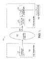
- the basic T/R communication systemis shown in FIG. 1 and is embodied by the system 100 .
- the information signalis transmitted by transmitter 103 of the T/R transmitter system 101 into the channel medium 104 where it is available for the T/R receiver system 102 at 105 . It is then digitized in receiver 106 for T/R processing in 107 where the transmitted information signal at 103 is recovered at the link station at 108 .
- the first realizationis probably the most advantageous by performing T/R during transmission thereby mitigating the effects of the medium directly.
- the pilot measurementis defined as z p ( t ) ⁇ g ( r;t )* p ( t ), [Pilot] (Equation 9) where z p is the pilot measurement, which can also be contaminated with additive noise; g is the spatio-temporal Green's function of the channel; and, p is the known, transmitted pilot signal.
- the purpose of the pilot in this case, as well as that of equalization,is to estimate the Green's function which is used in the final receiver design to mitigate the distortion effects created by the channel medium and unknown transfer characteristics of the measurement system.
- the pilotis not only used to estimate the Green's function, but also to implement the receiver by convolution as will be discussed below.
- the information measurementis defined by z i ( t ) ⁇ g ( r;t )* i ( t ), [Information] (Equation 10) where z i is the information measurement; and, i is the transmitted information signal.
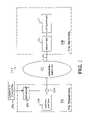
- the T/R Transmission Based Receiver 200 using the channel Green's function on transmissionis shown in FIG. 2 and is Realization No. 1 of the set of T/R receivers.
- the channel Green's function 202is first estimated, reversed digitally 203 , and convolved 206 with the information signal 205 for transmission through the channel medium 207 .
- the input 209 to the T/R receiveris defined as Z igX (t) with the subscript representing the information signal (i), convolved with the Green's function, (g), on transmission (X) is digitized (A/D converter) in the receiver 210 of the T/R Receiver 208 .
- Equation 12Clearly, if C g ⁇ (t) ⁇ C gg (t) and C gg (t) is impulsive, then i(t) is recovered directly by this realization. However, in reality, we have the autocorrelation function, C gg (t), that acts as a window function filtering or smearing i(t). It is also interesting to note with this particular realization that if a sensor array replaces the single sensor transmitter used for point-to-point communications, then the optimal spatial-temporal matched-filter is additionally achieved with the added gain in SNR afforded by the array as well as the focusing capability of the T/R operation. Next we consider a second realization using a similar structure.
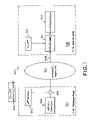
- the T/R Transmission Based Receiver 300 using the pilot measurement on transmissionis shown in FIG. 3 and is Realization No. 2 of the set of T/R receivers. It is an alternate realization of the T/R receiver using the pilot measurement.
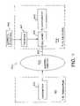
- the T/R Transmitter 401transmits the information signal 402 through the channel medium 403 resulting in the received measurement 405 .
- Realization No. 4 of the set of T/R receiversis the T/R Reception Based Receiver 500 with pilot measurement 509 on reception is shown in FIG. 5 .
- the T/R Transmitter 501transmits the information signal 502 through the channel medium 503 resulting in the received measurement 505 .
- Green's functionOne of the critical steps in the implementation of any communications receiver is how it “equalizes” or attempts to remove the deleterious effects of mitigating the channel medium (Green's function).
- the estimated Green's functionis required before the receiver can be constructed.
- the applicantsdiscuss some approaches to estimate the Green's function from noisy received data.
- the channel Green's functionis an integral part of the two T/R receiver realizations. It can be estimated from the pilot measurement of Eq. 9 and is similar to the operations used for equalization, but is much better conditioned numerically for solution, since the forward rather than the inverse filter is required for T/R.
- the estimated Green's functionis used in the realizations to mitigate the distortion effects created by the channel medium and unknown transfer characteristics of the measurement system. We describe two methods of obtaining the required pilot measurements in FIG. 6 . Since reciprocity holds, the pilot can be transmitter from either the transmission or reception side of the implementation to obtain the measured data for processing.
- the estimate, ⁇ (r;t),is obtained using the optimal Wiener solution obtained from the pilot measurement by solving
- a more efficient method to estimate the Green's functionis using a chirp input to excite the channel medium.
- the chirpis simply a frequency-modulated signal that is swept over the presumed bandwidth of the channel. It is well-known that the autocorrelation of a chirp closely approximates and impulse; therefore, when used in the T/R Receiver Realizations No. 2 ( FIG. 3 ) and No. 4 ( FIG. 5 ) the resulting outputs are much simpler and produce the desired results.
- Transceiver 601transmits the pilot 602 through the channel medium 603 to the reception Transceiver 604 where the measurement 605 is digitized in the Pilot receiver 606 and output 605 for further processing at the Link station.
- the Link stationit may be desirable to have the Link station perform the pilot transmission.
- the pilot 608is transmitted from the Transceiver 604 through the medium 603 where the measurement 609 is received on Transceiver 601 is digitized in the Pilot receiver 610 and output 611 for processing at the Master station.
- the T/R transmitter 101includes a Transmit System 103 .
- the Transmit System 103comprises a code generator, digitizers (A/D and D/A), amplifier, microprocessor (convolution), reverser (FIFO shift register) and other data (e.g., pilot, pilot measurement, etc.).
- Channel Medium 104is the channel over which the information is to be sent and is characterized by its Green's function.
- the T/R Receiver 102comprises of the Receive System 106 and T/R Equalizer 107 .
- the Receive System 106comprises an amplifier and filter, digitizer and matched-filter for synchronization.
- the T/R Equalizer 107comprises a microprocessor (convolution), reverser (FIFO shift register) and other data (e.g., pilot, pilot measurement, etc.)
- an embodiment of a basic T/R Communication system 100 using any of the possible realizations discussed above or for that matter any realization using the time reversal approachconsists of a T/R Transmitter 101 including a Transmit system 103 which may include the estimated Green's function in its implementation, a digitizer, and an information code generator as well as a microprocessor to perform convolution on transmission 103 when required.
- a Transmit system 103which may include the estimated Green's function in its implementation, a digitizer, and an information code generator as well as a microprocessor to perform convolution on transmission 103 when required.
- the information codeis transmitted 103 from the T/R Transmitter 101 through the channel medium 104 it is received 105 on the T/R Receiver 102 , digitized and processed (bandpass filtered) 106 and the processed using any device (e.g., microprocessor) to perform the receiver functions 107 producing the output information 108 .
- any devicee.g., microprocessor
- 2 ] ⁇ C _ ⁇ ( r o ; ⁇ ) ( Equation ⁇ ⁇ 35 ) which implies that K ( ⁇ ) ⁇ C *( r o ; ⁇ )⁇ ( ⁇ ) ⁇ C ( r o ; ⁇ ) (Equation 36) with
- This propertycan easily be shown by the system 800 depicted in FIG. 8 by extending the problem to include multiple Link stations, say N p , each one ( 801 , 808 , 809 , 810 ) identified first by individual coded messages ( 802 , 805 , 806 , 807 ) following the same procedure as Prada [].
- the channel medium vector 803becomes a N p ⁇ L matrix, C(r; ⁇ ) and the weight becomes a set of weights, one for each Link station ( 801 , 808 , 809 , 810 ), defined by a diagonal matrix, A(r o ; ⁇ ) ⁇ R N P ⁇ N P .
- ⁇diag[ ⁇ 1 2 ( ⁇ ) . . . ⁇ N p 2 ( ⁇ ) 0 . . . 0] of rank N p contains the singular values (squared-eigenvalues).
- the Link stations ( 901 , 908 , 909 , 910 )are identified first by individual coded messages using their individual eigenvectors ( 902 , 905 , 906 , 907 ) “learned” from the medium 903 following the same procedure as Prada [ ].
- the present inventionprovides a communication system that comprises means for transmitting a signal through a channel medium, means for receiving the signal, means for digitizing the signal, and means for time-reversing the digitized signal.
- the means for time-reversing the digitized signalis operatively connected to the transmitter.
- the means for time-reversing the digitized signalis operatively connected to the receiver.
- the means for digitizing the signalis operatively connected to the transmitter.
- the means for digitizing the signalis operatively connected to the receiver.
- the means for time-reversing the digitized signal and the means for digitizing the signalare operatively connected to the transmitter.
- the means for time-reversing the digitized signal and the means for digitizing the signalare operatively connected to the receiver.
Landscapes
- Engineering & Computer Science (AREA)
- Computer Networks & Wireless Communication (AREA)
- Signal Processing (AREA)
- Power Engineering (AREA)
- Physics & Mathematics (AREA)
- Mathematical Physics (AREA)
- Cable Transmission Systems, Equalization Of Radio And Reduction Of Echo (AREA)
- Transceivers (AREA)
Abstract
Description
where the applicants have also shown the equivalent Fourier transform representation. Based on the underlying theory, applicants “re-transmit” or “back-propagate” from r, through the channel, back to the original source position at ro, and choose to transmit the time-reversed signal, R(r,−t), then
utilizing the Fourier transform conjugation property. But substituting the reversed signal into this equation and invoking the Reciprocity Theorem (C(ro, r; t)≡C(r, ro; t)) interchanging source and receiver position gives
which implies that the reversed signals re-transmitted through the medium will “focus” the enhanced energy (with gain K) back to the original source position with no change in phase because of the magnitude-squared channel Green's function, that is,
Î(ro,ω)∝K(ω)I(ro,ω), (Equation 4)
precisely demonstrating the broadband version of phase conjugation. Clearly, this relation is more complicated, and more sophisticated representations include sensor transfer functions, noise, etc. Knowledge of the detailed channel Green's function is not required (no modeling) explicitly. This simple property can be extended to random media. Next the applicants describe how the TR principle can be applied to the communications problem.
z(t)=sout(t)+nout(t)=g(r;t)*[s(t)+n(t)], (Equation 5)
for z(t), the noisy measurement, so(t), the output signal consisting of the convolution of s(t), the transmitted signal (information) and g(r;t), the spatio-temporal channel Green's function response. Note here we use g(r;t) instead of C(r;t) the previous discussion. The output noise, nout(t), is also the convolution of the input noise, n(t), an additive random (white) zero mean, noise of variance, σn2. The matched-filter problem based on the model of Eq. 5 is given a “known” signal, s(t), in additive white noise, find the filter response, f (t), that maximizes the SNRoutdefined by
for ξs
|f(t)*g(r,ro;t)|2≦ξf×ξg, (Equation 7)
that is satisfied with equality at some time T, if
f(t)=g(r,ro;T−t). (Equation 8)
zp(t)≡g(r;t)*p(t), [Pilot] (Equation 9)
where zpis the pilot measurement, which can also be contaminated with additive noise; g is the spatio-temporal Green's function of the channel; and, p is the known, transmitted pilot signal. The purpose of the pilot in this case, as well as that of equalization, is to estimate the Green's function which is used in the final receiver design to mitigate the distortion effects created by the channel medium and unknown transfer characteristics of the measurement system. The pilot is not only used to estimate the Green's function, but also to implement the receiver by convolution as will be discussed below.
zi(t)≡g(r;t)*i(t), [Information] (Equation 10)
where ziis the information measurement; and, i is the transmitted information signal.
zigX(t)≡zi(t)*ĝ(r;−t)=g(r;t)*ĝ(r;−t)*i(t)=Cgĝ(t)*i(t), (Equation 11)
where Cgĝ(t) is the correlation function and therefore, the
RigX(t)=zigX(t). (Equation 12)
Clearly, if Cgĝ(t)˜Cgg(t) and Cgg(t) is impulsive, then i(t) is recovered directly by this realization. However, in reality, we have the autocorrelation function, Cgg(t), that acts as a window function filtering or smearing i(t). It is also interesting to note with this particular realization that if a sensor array replaces the single sensor transmitter used for point-to-point communications, then the optimal spatial-temporal matched-filter is additionally achieved with the added gain in SNR afforded by the array as well as the focusing capability of the T/R operation. Next we consider a second realization using a similar structure.
zipX(t)=zi(t)*zp(−t)=Cgg(t)*p(−t)*i(t). (Equation 13)
RipX(t)=zipX(t)*p(t)=Cgg(t)*Cpp(t)*i(t), (Equation 14)
where again if both Cggand Cppare impulsive, i(t), is recovered directly. Realistically, we can think of the information signal as being filtered or smeared by both.
RigR(t)=zi(t)*g(r;−t)=Cgg(t)*i(t), (Equation 15)
which is mathematically identical to RigX(t) with the exception that the mitigation of the
RipR(t)=zi(t)*zip(−t)*p(t)=Cgg(t)*Cpp(t)*i(t), (Equation 16)
which is mathematically equivalent to RipX(t), but with the potential uncertainty problems discussed in Realization No. 3 above.
and ∈ is defined as the output error. The solution of this problem leads to the well-known Wiener filter given by
ĝ=Cpp−1czp, (Equation 18)
where Cppis a M×M correlation matrix and czpis a M-cross correlation vector with
for
ĝT≡[{circumflex over (g)}(r;0) . . . {circumflex over (g)}(r;M−1)] andpT(t)≡[p(t) . . .p(t−M+1)].
T(rl;t)=C(rl,ro;t)*p(ro;t) (Equation 20)
or equivalently in the temporal frequency domain
T(rl;ω)=C(rl,ro;ω)×P(ro;ω) (Equation 21)
Next the signal received on each
{circumflex over (p)}(ro;t)=C(ro,rl;t)*T(rl;−t)=C(ro,rl;t)*[C(rl,ro;−t)*p(ro;−t)] (Equation 22)
Taking Fourier transforms and assuming reciprocity holds (C(ro,rl;t)=C(rl,ro;t)), we have
{circumflex over (P)}(ro;ω)=C(ro,rl;ω)C*(rl,ro;ω)P*(ro;ω)=|C(ro;ω)=|C(ro;ω)|2P*(ro;ω) (Equation 23)
From time-reversal theory this relation states that the reversed
T(t)=C(ro;t)*p(ro;t) (Equation 24)
and equivalently
T(ω)=C(ro;ω)×P(ro;ω) (Equation 25)
Following the same arguments as before in the temporal frequency domain, we obtain
{circumflex over (P)}(ro;ω)=C′(ro;ω)×C(ro;ω)P(ro;ω) (Equation 26)
or
{circumflex over (P)}(ro;ω)=|C(ro;ω)|2P(ro;ω) (Equation 27)
implying that not only do we focus
R(ro;t)=CT(ro;t)*i(t) (Equation 28)
or equivalently in the frequency domain
R(ro;ω)=CT(ro;ω)×I(ω) (Equation 29)
where R is defined as the forward propagation relation. Next suppose the Link station “repeats” the received code and modifies it by some weighting function, a(ro;t) , then the backward propagation relation to the transceiver array is
T(ω)=C(ro;ω)A(ro;ω)R(ro;ω)=└C(ro;ω)A(ro;ω)C′(ro;ω)┘I(ω) (Equation 30)
Thus, the transfer matrix, K ∈ CL×Lfrom the Link station to the Master station transceiver array is defined by
K(ω)≡C(ro;ω)A(ro;ω)C′(ro;ω) (Equation 31)
with corresponding input-output relation
T(ω)=K(ω)×I(ω) (Equation 32)
Following Prada [ ], it is possible to focus transmitted energy exclusively on the Link station without leaking energy on other stations by using the time-reversed channel medium response Green's functions, Cl(ro;−t) . Therefore, the pressure-field received at rois
Next, letC*(ro;ω) (obtained from pilot signal transmission of
T(ω)=K(ω)×C*(ro;ω)=A(ro;ω)×C(eo;ω)×CT(ro;ω)×C*(ro;ω) (Equation 34)
and therefore,
which implies that
K(ω)×C*(ro;ω)=λ(ω)×C(ro;ω) (Equation 36)
with
Multiplying both sides of Eq. 36 by, K′(ω), then
[K′(ω)K(ω)]C*(ro;ω)=λ2(ω)C*(ro;ω) (Equation 37)
which is an eigen-equation with eigenvalue, λ2(ω) and corresponding eigenvector,C*(ro;ω), since the product K′(ω)K(ω) is Hermitian. This relation shows that sinceC*(ro;ω) is an eigenvector of K′(ω)K(ω), then therefore, it is also an eigenvector of K(ω) (e.g. see Lawson [] Theorem 4.1). Thus, the eigenvector signal,C*(ro;ω), transmitted through the channel medium will focus only on the Link station at ro.
K(ω)=CT(r;ω)×A(r;ω)×C(r;107 ) (Equation 38)
and the corresponding input-output relation remains the same as before. The forward propagation811 to all Link stations (801,808,809,810) is now given by
R(ω)=C(r;ω)×I(ω) (Equation 39)
Assuming single scattering, the back propagation811 is given by
T(ω)=CT(r;ω)A(r;ω)R(r;ω)=CT(r;ω)A(r;ω)[C(r;ω)I(ω)]=K(ω)×I(ω) (Equation 40)
As before let the input signal811 be an eigenvector from the jthstation,Cj(r;−t) orCj* (r;ω), then back propagating811 gives
T(ω)=K(ω)×Cj*(ω)=CT(r;ω)A(r;ω)C(r;ω)×Cj*(r;ω) (Equation 41)
If ideally separated scatterers are assumed, then A is a diagonal matrix and theCj*(r;ω) are orthogonal, therefore multiplying out the last three terms in Eq. 41 gives a Np-vector
but sinceCmT(r;ω)Cn*(r;ω)=0 for m≠n, then only the jth-th column survives with element
whereejis a Np-unit vector with unity at the jth-row. Multiplying the Eq. 42 using the orthogonality property and the unit vector gives
T(ω)=CT(r;ω)ejλj(ω)Cj(r;ω) (Equation 43)
withCj(r;ω) the jth-column L-vector of C and therefore
K(ω)Cj*(r;ω)=λj(ω)Cj(r;ω) (Equation 44)
As before in Eq. 18, pre-multiplying both sides yields the eigen-equation
└KT(ω)K(ω)┘Cj*(r;ω)=λj2(ω)Cj*(r;ω) (Equation 45)
with eigenvalue, λj2(ω), and eigenvector,Cj*(r;ω), also an eigenvector of K. What this result implies is that for ideally separated stations, it is possible to transmit codes to each individually assuring complete isolation security between stations as well as any other listeners. It is also interesting to note that to solve this problem the singular value decomposition of the Hermitian matrix, KTK can be employed, that is
└KT(ω)K(ω)┘=E(ω)×Λ(ω)×E′(ω) (Equation 46)
where the L×L-matrix, Λ=diag[λ12(ω) . . . λN
Claims (51)
Priority Applications (4)
| Application Number | Priority Date | Filing Date | Title |
|---|---|---|---|
| US10/289,774US7460605B2 (en) | 2001-11-15 | 2002-11-06 | Time reversal communication system |
| PCT/US2002/036367WO2003045023A1 (en) | 2001-11-15 | 2002-11-12 | Time reversal communication system |
| AU2002343682AAU2002343682A1 (en) | 2001-11-15 | 2002-11-12 | Time reversal communication system |
| US11/271,334US7463690B2 (en) | 2002-11-06 | 2005-11-10 | Multi-channel time-reversal receivers for multi and 1-bit implementations |
Applications Claiming Priority (2)
| Application Number | Priority Date | Filing Date | Title |
|---|---|---|---|
| US33323101P | 2001-11-15 | 2001-11-15 | |
| US10/289,774US7460605B2 (en) | 2001-11-15 | 2002-11-06 | Time reversal communication system |
Related Child Applications (1)
| Application Number | Title | Priority Date | Filing Date |
|---|---|---|---|
| US11/271,334Continuation-In-PartUS7463690B2 (en) | 2002-11-06 | 2005-11-10 | Multi-channel time-reversal receivers for multi and 1-bit implementations |
Publications (2)
| Publication Number | Publication Date |
|---|---|
| US20030138053A1 US20030138053A1 (en) | 2003-07-24 |
| US7460605B2true US7460605B2 (en) | 2008-12-02 |
Family
ID=26965835
Family Applications (1)
| Application Number | Title | Priority Date | Filing Date |
|---|---|---|---|
| US10/289,774Expired - LifetimeUS7460605B2 (en) | 2001-11-15 | 2002-11-06 | Time reversal communication system |
Country Status (3)
| Country | Link |
|---|---|
| US (1) | US7460605B2 (en) |
| AU (1) | AU2002343682A1 (en) |
| WO (1) | WO2003045023A1 (en) |
Cited By (27)
| Publication number | Priority date | Publication date | Assignee | Title |
|---|---|---|---|---|
| US20120257660A1 (en)* | 2008-10-10 | 2012-10-11 | Smith David F | Techniques and systems for wireless communications |
| US8498658B2 (en) | 2009-09-03 | 2013-07-30 | Ziva Corporation | Techniques and systems for providing data over power in communications based on time reversal |
| US20140144239A1 (en)* | 2011-07-08 | 2014-05-29 | Pascal Vouagner | Method and device for checking structures by time reversal |
| US9226304B2 (en) | 2014-03-10 | 2015-12-29 | Origin Wireless, Inc. | Time-reversal wireless paradigm for internet of things |
| US9313020B2 (en) | 2014-02-19 | 2016-04-12 | Origin Wireless, Inc. | Handshaking protocol for time-reversal system |
| US9407306B2 (en) | 2014-04-25 | 2016-08-02 | Origin Wireless, Inc. | Quadrature amplitude modulation for time-reversal systems |
| US9559874B2 (en) | 2013-08-16 | 2017-01-31 | Origin Wireless, Inc. | Multiuser time-reversal division multiple access uplink system with parallel interference cancellation |
| US9686054B2 (en) | 2014-07-17 | 2017-06-20 | Origin Wireless, Inc. | Joint waveform design and interference pre-cancellation for time-reversal systems |
| US9755860B2 (en) | 2016-01-29 | 2017-09-05 | Industrial Technology Research Institute | Method of performing uplink channel estimation and base station using the same |
| US9882675B2 (en) | 2013-08-16 | 2018-01-30 | Origin Wireless, Inc. | Time-reversal wireless systems having asymmetric architecture |
| US9883511B1 (en) | 2012-12-05 | 2018-01-30 | Origin Wireless, Inc. | Waveform design for time-reversal systems |
| US9887864B1 (en) | 2014-03-10 | 2018-02-06 | Origin Wireless, Inc. | Methods, devices and systems of heterogeneous time-reversal paradigm enabling direct connectivity in internet of things |
| US10009148B1 (en) | 2015-01-22 | 2018-06-26 | Origin Wireless, Inc. | Time-reversal technologies for hybrid wireless networks |
| US10122409B2 (en) | 2012-12-03 | 2018-11-06 | University Of Maryland At College Park | Systems and methods for time-reversal division multiple access wireless broadband communications |
| US10129862B1 (en) | 2016-02-16 | 2018-11-13 | Origin Wireless, Inc. | Methods, devices, apparatus, and systems for medium access control in wireless communication systems utilizing spatial focusing effect |
| US10168414B2 (en) | 2014-07-17 | 2019-01-01 | Origin Wireless, Inc. | Wireless signals and techniques for determining locations of objects in multi-path environments |
| US10270642B2 (en) | 2012-12-05 | 2019-04-23 | Origin Wireless, Inc. | Method, apparatus, and system for object tracking and navigation |
| US10291460B2 (en) | 2012-12-05 | 2019-05-14 | Origin Wireless, Inc. | Method, apparatus, and system for wireless motion monitoring |
| US10327213B1 (en) | 2015-10-01 | 2019-06-18 | Origin Wireless, Inc. | Time-reversal communication systems |
| US10380881B2 (en) | 2015-12-09 | 2019-08-13 | Origin Wireless, Inc. | Method, apparatus, and systems for wireless event detection and monitoring |
| US10440705B2 (en) | 2012-12-05 | 2019-10-08 | Origin Wireless, Inc. | Method, apparatus, server, and systems of time-reversal technology |
| US10447094B2 (en) | 2016-05-03 | 2019-10-15 | Origin Wireless, Inc. | Method, system, and apparatus for wireless power transmission based on power waveforming |
| US10609711B1 (en) | 2015-03-05 | 2020-03-31 | Origin Wireless, Inc. | Time-reversal scalability for high network densification |
| US11025475B2 (en) | 2012-12-05 | 2021-06-01 | Origin Wireless, Inc. | Method, apparatus, server, and systems of time-reversal technology |
| US11108429B1 (en)* | 2020-06-01 | 2021-08-31 | Raytheon Company | Covert acoustic communications through solid propagation channels using spread spectrum coding and adaptive channel pre-distortion |
| US11495243B2 (en) | 2020-07-30 | 2022-11-08 | Lawrence Livermore National Security, Llc | Localization based on time-reversed event sounds |
| US11538322B2 (en) | 2020-12-23 | 2022-12-27 | Lawrence Livermore National Security, Llc | Event detection unit |
Families Citing this family (25)
| Publication number | Priority date | Publication date | Assignee | Title |
|---|---|---|---|---|
| EP1551303A4 (en)* | 2002-05-16 | 2009-03-18 | Karmanos B A Cancer Inst | COMBINED DIAGNOSTIC METHOD AND SYSTEM AND ULTRASONIC TREATMENT SYSTEM INCLUDING NON-INVASIVE THERMOMETRY, CONTROL AND AUTOMATION OF ABLATION |
| US7463690B2 (en)* | 2002-11-06 | 2008-12-09 | Lawrence Livermore National Security, Llc | Multi-channel time-reversal receivers for multi and 1-bit implementations |
| US7423931B2 (en)* | 2003-07-08 | 2008-09-09 | Lawrence Livermore National Security, Llc | Acoustic system for communication in pipelines |
| WO2005015789A1 (en) | 2003-07-08 | 2005-02-17 | The Regents Of The University Of California | System for communication in pipelines |
| FR2868894B1 (en)* | 2004-04-13 | 2006-08-18 | Centre Nat Rech Scient Cnrse | METHOD FOR TEMPORALLY REVERSING WAVE |
| WO2007076039A2 (en)* | 2005-12-20 | 2007-07-05 | Massachusetts Institute Of Technology | Communications and power harvesting system for in-pipe wireless sensor networks |
| US8870771B2 (en) | 2007-05-04 | 2014-10-28 | Barbara Ann Karmanos Cancer Institute | Method and apparatus for categorizing breast density and assessing cancer risk utilizing acoustic parameters |
| US10201324B2 (en) | 2007-05-04 | 2019-02-12 | Delphinus Medical Technologies, Inc. | Patient interface system |
| US8330642B2 (en)* | 2007-07-09 | 2012-12-11 | Carnegie Mellon University | Imaging by time reversal beamforming |
| US8195112B1 (en)* | 2008-06-18 | 2012-06-05 | Marvell International Ltd. | Time-reversal-based communication |
| FR2933252A1 (en)* | 2008-06-27 | 2010-01-01 | France Telecom | METHOD FOR DYNAMICALLY MONITORING THE FOCUSING OF A PRE-EQUALIZED SIGNAL BY TEMPORARY RETURN |
| WO2009156705A2 (en)* | 2008-06-27 | 2009-12-30 | France Telecom | Method of estimating the quality of focusing of a signal pre-equalized by time reversal |
| EP2427991B1 (en)* | 2009-05-07 | 2018-04-18 | Orange | Pre-equalizing method using fdd time reversal |
| EP2427992B1 (en)* | 2009-05-07 | 2014-10-29 | Orange | Method for pre-equalizing a data signal by fdd time reversal |
| CN102869301B (en) | 2010-02-12 | 2016-06-29 | 戴尔菲纳斯医疗科技公司 | The method characterizing the tissue of patient |
| US9144403B2 (en) | 2010-02-12 | 2015-09-29 | Delphinus Medical Technologies, Inc. | Method of characterizing the pathological response of tissue to a treatment plan |
| CN102005828B (en)* | 2010-11-30 | 2012-09-12 | 电子科技大学 | Wireless sensor network node wireless charging system and method based on time reversal |
| EP2705726A4 (en)* | 2011-05-02 | 2015-04-29 | Ziva Corp | Distributed co-operating nodes using time reversal |
| US9413571B2 (en)* | 2012-03-06 | 2016-08-09 | University Of Maryland | System and method for time reversal data communications on pipes using guided elastic waves |
| US9763641B2 (en) | 2012-08-30 | 2017-09-19 | Delphinus Medical Technologies, Inc. | Method and system for imaging a volume of tissue with tissue boundary detection |
| US10123770B2 (en) | 2013-03-13 | 2018-11-13 | Delphinus Medical Technologies, Inc. | Patient support system |
| US10285667B2 (en) | 2014-08-05 | 2019-05-14 | Delphinus Medical Technologies, Inc. | Method for generating an enhanced image of a volume of tissue |
| US20170170885A1 (en)* | 2015-12-09 | 2017-06-15 | Qinghua Li | Beamforming channel smoothing |
| US10484208B2 (en) | 2018-02-23 | 2019-11-19 | Wistron Neweb Corporation | Anomalies detection system and method for structure |
| CN108880004B (en)* | 2018-06-25 | 2020-06-12 | 华南理工大学 | Time reversal wireless energy transmission system and method with low-speed sampling compensation |
Citations (19)
| Publication number | Priority date | Publication date | Assignee | Title |
|---|---|---|---|---|
| DE3842423A1 (en) | 1988-12-16 | 1990-06-21 | Ant Nachrichtentech | Method for determining the correlation increments of the Viterbi algorithm |
| EP0498422A2 (en) | 1991-02-08 | 1992-08-12 | Canon Kabushiki Kaisha | Optical interconnection networks and processes |
| US5155742A (en) | 1991-05-03 | 1992-10-13 | Bell Communications Research, Inc. | Time dispersion equalizer receiver with a time-reversal structure for TDMA portable radio systems |
| US5335250A (en)* | 1992-10-22 | 1994-08-02 | Ericsson Ge Mobile Communications Inc. | Method and apparatus for bidirectional demodulation of digitally modulated signals |
| US5428999A (en) | 1992-10-02 | 1995-07-04 | Universite Paris Vii | Method and apparatus for acoustic examination using time reversal |
| US5809083A (en)* | 1994-11-23 | 1998-09-15 | At&T Wireless Services, Inc. | Differentially encoded pilot word system and method for wireless transmissions of digital data |
| US5914959A (en)* | 1996-10-31 | 1999-06-22 | Glenayre Electronics, Inc. | Digital communications system having an automatically selectable transmission rate |
| EP0961436A2 (en) | 1998-05-29 | 1999-12-01 | Nec Corporation | Method of identifying a frame for erasure in a digital data transmission system |
| US6035197A (en)* | 1994-12-29 | 2000-03-07 | Cellco Partnership | Method and system for providing a handoff from a CDMA cellular telephone system |
| WO2001000446A1 (en) | 1999-06-25 | 2001-01-04 | Suma Investment Holding | Power unit for managing a vehicle flashers |
| US6173011B1 (en)* | 1998-05-28 | 2001-01-09 | Glenayre Electronics, Inc. | Forward-backward channel interpolator |
| US6301291B1 (en)* | 2000-02-03 | 2001-10-09 | Tantivy Communications, Inc. | Pilot symbol assisted modulation and demodulation in wireless communication systems |
| US20010037075A1 (en) | 2000-03-15 | 2001-11-01 | The Regents Of The University Of California | Method and apparatus for dynamic focusing of ultrasound energy |
| US20020176485A1 (en)* | 2001-04-03 | 2002-11-28 | Hudson John E. | Multi-cast communication system and method of estimating channel impulse responses therein |
| US20020186761A1 (en)* | 2001-06-04 | 2002-12-12 | Corbaton Ivan Jesus Fernandez | Method and apparatus for estimating the signal to interference-plus-noise ratio of a wireless channel |
| US6643520B1 (en)* | 1998-08-01 | 2003-11-04 | Samsung Electronics Co., Ltd. | Device and method for controlling initial transmission power of forward link channel in mobile communications system |
| US6658050B1 (en)* | 1998-09-11 | 2003-12-02 | Ericsson Inc. | Channel estimates in a CDMA system using power control bits |
| US6728233B1 (en)* | 1998-07-16 | 2004-04-27 | Samsung Electronics Co., Ltd | Processing packet data in mobile communication system |
| US6834043B1 (en)* | 2000-07-24 | 2004-12-21 | Motorola, Inc. | Method and device for exploiting transmit diversity in time varying wireless communication systems |
Family Cites Families (1)
| Publication number | Priority date | Publication date | Assignee | Title |
|---|---|---|---|---|
| US7272192B2 (en)* | 2000-04-14 | 2007-09-18 | Board Of Trustees Of The Leland Stanford Junior University | Time-reversal block transmit diversity system for channels with intersymbol interference and method |
- 2002
- 2002-11-06USUS10/289,774patent/US7460605B2/ennot_activeExpired - Lifetime
- 2002-11-12WOPCT/US2002/036367patent/WO2003045023A1/ennot_activeApplication Discontinuation
- 2002-11-12AUAU2002343682Apatent/AU2002343682A1/ennot_activeAbandoned
Patent Citations (19)
| Publication number | Priority date | Publication date | Assignee | Title |
|---|---|---|---|---|
| DE3842423A1 (en) | 1988-12-16 | 1990-06-21 | Ant Nachrichtentech | Method for determining the correlation increments of the Viterbi algorithm |
| EP0498422A2 (en) | 1991-02-08 | 1992-08-12 | Canon Kabushiki Kaisha | Optical interconnection networks and processes |
| US5155742A (en) | 1991-05-03 | 1992-10-13 | Bell Communications Research, Inc. | Time dispersion equalizer receiver with a time-reversal structure for TDMA portable radio systems |
| US5428999A (en) | 1992-10-02 | 1995-07-04 | Universite Paris Vii | Method and apparatus for acoustic examination using time reversal |
| US5335250A (en)* | 1992-10-22 | 1994-08-02 | Ericsson Ge Mobile Communications Inc. | Method and apparatus for bidirectional demodulation of digitally modulated signals |
| US5809083A (en)* | 1994-11-23 | 1998-09-15 | At&T Wireless Services, Inc. | Differentially encoded pilot word system and method for wireless transmissions of digital data |
| US6035197A (en)* | 1994-12-29 | 2000-03-07 | Cellco Partnership | Method and system for providing a handoff from a CDMA cellular telephone system |
| US5914959A (en)* | 1996-10-31 | 1999-06-22 | Glenayre Electronics, Inc. | Digital communications system having an automatically selectable transmission rate |
| US6173011B1 (en)* | 1998-05-28 | 2001-01-09 | Glenayre Electronics, Inc. | Forward-backward channel interpolator |
| EP0961436A2 (en) | 1998-05-29 | 1999-12-01 | Nec Corporation | Method of identifying a frame for erasure in a digital data transmission system |
| US6728233B1 (en)* | 1998-07-16 | 2004-04-27 | Samsung Electronics Co., Ltd | Processing packet data in mobile communication system |
| US6643520B1 (en)* | 1998-08-01 | 2003-11-04 | Samsung Electronics Co., Ltd. | Device and method for controlling initial transmission power of forward link channel in mobile communications system |
| US6658050B1 (en)* | 1998-09-11 | 2003-12-02 | Ericsson Inc. | Channel estimates in a CDMA system using power control bits |
| WO2001000446A1 (en) | 1999-06-25 | 2001-01-04 | Suma Investment Holding | Power unit for managing a vehicle flashers |
| US6301291B1 (en)* | 2000-02-03 | 2001-10-09 | Tantivy Communications, Inc. | Pilot symbol assisted modulation and demodulation in wireless communication systems |
| US20010037075A1 (en) | 2000-03-15 | 2001-11-01 | The Regents Of The University Of California | Method and apparatus for dynamic focusing of ultrasound energy |
| US6834043B1 (en)* | 2000-07-24 | 2004-12-21 | Motorola, Inc. | Method and device for exploiting transmit diversity in time varying wireless communication systems |
| US20020176485A1 (en)* | 2001-04-03 | 2002-11-28 | Hudson John E. | Multi-cast communication system and method of estimating channel impulse responses therein |
| US20020186761A1 (en)* | 2001-06-04 | 2002-12-12 | Corbaton Ivan Jesus Fernandez | Method and apparatus for estimating the signal to interference-plus-noise ratio of a wireless channel |
Non-Patent Citations (2)
| Title |
|---|
| Bellanger, "Adaptive Digital Filters," 1987, Marcel Dekker, Inc., New York, NY, XP002236665, paragraph 12.3.2 (4 pages). |
| Zazo, S., et al., "Pre-Rake and Multiuser Detection Techniques in UTRA-TDD Systems," VTC 2000-Spring, 2000, IEEE 51<SUP>st</SUP>. Vehicular Technology Conf., Proceedings, Tokyo, Japan, May 15-18, 2000, IEEE Vehicular Technology Conf., New York, NY, IEEE, US, vol. 3 of 3, Conf. 51, May 15, 2000, pp. 2069-2072. |
Cited By (42)
| Publication number | Priority date | Publication date | Assignee | Title |
|---|---|---|---|---|
| US8989247B2 (en)* | 2008-10-10 | 2015-03-24 | Ziva Corporation | Reducing signal degradation in wireless communications based on time reversal |
| US9419703B2 (en) | 2008-10-10 | 2016-08-16 | Ziva Corporation | Techniques and systems for wireless communications |
| US20130223503A1 (en)* | 2008-10-10 | 2013-08-29 | Ziva Corporation | Reducing signal degradation in wireless communications based on time reversal |
| US8411765B2 (en)* | 2008-10-10 | 2013-04-02 | Ziva Corporation | Techniques and systems for wireless communications |
| US20120257660A1 (en)* | 2008-10-10 | 2012-10-11 | Smith David F | Techniques and systems for wireless communications |
| US8498658B2 (en) | 2009-09-03 | 2013-07-30 | Ziva Corporation | Techniques and systems for providing data over power in communications based on time reversal |
| US8743976B2 (en) | 2009-09-03 | 2014-06-03 | Ziva Corporation | Techniques and systems for communications based on time reversal pre-coding |
| US20140144239A1 (en)* | 2011-07-08 | 2014-05-29 | Pascal Vouagner | Method and device for checking structures by time reversal |
| US9322808B2 (en)* | 2011-07-08 | 2016-04-26 | 01Db-Metravib | Method and device for checking structures by time reversal |
| US10122409B2 (en) | 2012-12-03 | 2018-11-06 | University Of Maryland At College Park | Systems and methods for time-reversal division multiple access wireless broadband communications |
| US10291460B2 (en) | 2012-12-05 | 2019-05-14 | Origin Wireless, Inc. | Method, apparatus, and system for wireless motion monitoring |
| US10270642B2 (en) | 2012-12-05 | 2019-04-23 | Origin Wireless, Inc. | Method, apparatus, and system for object tracking and navigation |
| US11025475B2 (en) | 2012-12-05 | 2021-06-01 | Origin Wireless, Inc. | Method, apparatus, server, and systems of time-reversal technology |
| US10440705B2 (en) | 2012-12-05 | 2019-10-08 | Origin Wireless, Inc. | Method, apparatus, server, and systems of time-reversal technology |
| US9883511B1 (en) | 2012-12-05 | 2018-01-30 | Origin Wireless, Inc. | Waveform design for time-reversal systems |
| US9882675B2 (en) | 2013-08-16 | 2018-01-30 | Origin Wireless, Inc. | Time-reversal wireless systems having asymmetric architecture |
| US9900794B2 (en) | 2013-08-16 | 2018-02-20 | Origin Wireless, Inc. | Time-reversal wireless systems having asymmetric architecture |
| US9559874B2 (en) | 2013-08-16 | 2017-01-31 | Origin Wireless, Inc. | Multiuser time-reversal division multiple access uplink system with parallel interference cancellation |
| US9794156B2 (en) | 2014-02-19 | 2017-10-17 | Origin Wireless, Inc. | Handshaking protocol for time-reversal system |
| US9825838B2 (en) | 2014-02-19 | 2017-11-21 | Origin Wireless, Inc. | Handshaking protocol for time-reversal system |
| US9313020B2 (en) | 2014-02-19 | 2016-04-12 | Origin Wireless, Inc. | Handshaking protocol for time-reversal system |
| US9781700B2 (en) | 2014-03-10 | 2017-10-03 | Origin Wireless, Inc. | Time-reversal wireless paradigm for internet of things |
| US9226304B2 (en) | 2014-03-10 | 2015-12-29 | Origin Wireless, Inc. | Time-reversal wireless paradigm for internet of things |
| US9887864B1 (en) | 2014-03-10 | 2018-02-06 | Origin Wireless, Inc. | Methods, devices and systems of heterogeneous time-reversal paradigm enabling direct connectivity in internet of things |
| US9402245B2 (en) | 2014-03-10 | 2016-07-26 | Origin Wireless, Inc. | Time-reversal wireless paradigm for internet of things |
| US9407306B2 (en) | 2014-04-25 | 2016-08-02 | Origin Wireless, Inc. | Quadrature amplitude modulation for time-reversal systems |
| US9736002B2 (en) | 2014-04-25 | 2017-08-15 | Origin Wireless, Inc. | Quadrature amplitude modulation for time-reversal systems |
| US10168414B2 (en) | 2014-07-17 | 2019-01-01 | Origin Wireless, Inc. | Wireless signals and techniques for determining locations of objects in multi-path environments |
| US9686054B2 (en) | 2014-07-17 | 2017-06-20 | Origin Wireless, Inc. | Joint waveform design and interference pre-cancellation for time-reversal systems |
| US10014982B1 (en) | 2015-01-22 | 2018-07-03 | Origin Wireless, Inc. | Time-reversal technologies for hybrid wireless networks |
| US10009148B1 (en) | 2015-01-22 | 2018-06-26 | Origin Wireless, Inc. | Time-reversal technologies for hybrid wireless networks |
| US10609711B1 (en) | 2015-03-05 | 2020-03-31 | Origin Wireless, Inc. | Time-reversal scalability for high network densification |
| US10327213B1 (en) | 2015-10-01 | 2019-06-18 | Origin Wireless, Inc. | Time-reversal communication systems |
| US10380881B2 (en) | 2015-12-09 | 2019-08-13 | Origin Wireless, Inc. | Method, apparatus, and systems for wireless event detection and monitoring |
| US9755860B2 (en) | 2016-01-29 | 2017-09-05 | Industrial Technology Research Institute | Method of performing uplink channel estimation and base station using the same |
| US10129862B1 (en) | 2016-02-16 | 2018-11-13 | Origin Wireless, Inc. | Methods, devices, apparatus, and systems for medium access control in wireless communication systems utilizing spatial focusing effect |
| US10447094B2 (en) | 2016-05-03 | 2019-10-15 | Origin Wireless, Inc. | Method, system, and apparatus for wireless power transmission based on power waveforming |
| US11108429B1 (en)* | 2020-06-01 | 2021-08-31 | Raytheon Company | Covert acoustic communications through solid propagation channels using spread spectrum coding and adaptive channel pre-distortion |
| US11495243B2 (en) | 2020-07-30 | 2022-11-08 | Lawrence Livermore National Security, Llc | Localization based on time-reversed event sounds |
| US12080318B2 (en) | 2020-07-30 | 2024-09-03 | Lawrence Livermore National Security, Llc | Localization based on time-reversed event sounds |
| US11538322B2 (en) | 2020-12-23 | 2022-12-27 | Lawrence Livermore National Security, Llc | Event detection unit |
| US11948438B2 (en) | 2020-12-23 | 2024-04-02 | Lawrence Livermore National Security, Llc | Event detection unit |
Also Published As
| Publication number | Publication date |
|---|---|
| WO2003045023A1 (en) | 2003-05-30 |
| AU2002343682A1 (en) | 2003-06-10 |
| WO2003045023A8 (en) | 2004-12-23 |
| US20030138053A1 (en) | 2003-07-24 |
Similar Documents
| Publication | Publication Date | Title |
|---|---|---|
| US7460605B2 (en) | Time reversal communication system | |
| US7463690B2 (en) | Multi-channel time-reversal receivers for multi and 1-bit implementations | |
| JP5539620B2 (en) | Method and apparatus for tracking an object | |
| Yon et al. | Sound focusing in rooms: The time-reversal approach | |
| US5412620A (en) | Hydroacoustic communications system robust to multipath | |
| Kyritsi et al. | One-bit time reversal for WLAN applications | |
| US20070177462A1 (en) | Scale adaptive filtering | |
| US10031207B2 (en) | Wideband channel equalization for signals propagated in lossy transmission media | |
| Candy et al. | Time-reversal processing for an acoustic communications experiment in a highly reverberant environment | |
| CN118519156A (en) | Multi-beam underwater sound detection method based on non-orthogonal multiple access technology | |
| EP1258160B1 (en) | Estimating the antenna angle-of-arrival using uplink weight vectors | |
| Catipovic et al. | Spatial diversity processing for underwater acoustic telemetry | |
| Candy et al. | Wideband multichannel time-reversal processing for acoustic communications in highly reverberant environments | |
| Rashid et al. | On the performance of a new wireless communication compact multichannel underwater receiver using a sphere vector sensor | |
| Candy et al. | Multichannel time-reversal processing for acoustic communications in a highly reverberant environment | |
| Silva et al. | Underwater communications using virtual time reversal in a variable geometry channel | |
| Wazenski et al. | Active, wideband detection and localization in an uncertain multipath environment | |
| Rodionov et al. | Application of incoherent multi-frequency signals for information transmission in a nonstationary hydroacoustic environment | |
| Josso et al. | Time-varying wideband underwater acoustic channel estimation for OFDM communications | |
| Lee et al. | Underwater digital communication using acoustic channel estimation | |
| Yuan et al. | Range and depth estimation using a vertical array in a correlated multipath environment | |
| Edelmann | An overview of time-reversal acoustic communications | |
| CN111082881A (en) | Multipath channel signal detection method and device based on time reversal | |
| US20020164955A1 (en) | Blind process and receiver to determine space-time parameters of a propagation channel | |
| Egbewande et al. | Measurement of a space-time noise mitigation technique |
Legal Events
| Date | Code | Title | Description |
|---|---|---|---|
| AS | Assignment | Owner name:REGENTS OF THE UNIVERSITY OF CALIFORNIA, THE, CALI Free format text:ASSIGNMENT OF ASSIGNORS INTEREST;ASSIGNORS:CANDY, JAMES V.;MEYER, ALAN W.;REEL/FRAME:013477/0156 Effective date:20021104 | |
| AS | Assignment | Owner name:U.S. DEPARTMENT OF ENERGY, CALIFORNIA Free format text:CONFIRMATORY LICENSE;ASSIGNOR:CALIFORNIA, UNIVERSITY OF;REEL/FRAME:014517/0098 Effective date:20030327 | |
| AS | Assignment | Owner name:LAWRENCE LIVERMORE NATIONAL SECURITY, LLC, CALIFOR Free format text:ASSIGNMENT OF ASSIGNORS INTEREST;ASSIGNOR:REGENTS OF THE UNIVERSITY OF CALIFORNIA, THE;REEL/FRAME:020012/0032 Effective date:20070924 Owner name:LAWRENCE LIVERMORE NATIONAL SECURITY, LLC,CALIFORN Free format text:ASSIGNMENT OF ASSIGNORS INTEREST;ASSIGNOR:REGENTS OF THE UNIVERSITY OF CALIFORNIA, THE;REEL/FRAME:020012/0032 Effective date:20070924 | |
| STCF | Information on status: patent grant | Free format text:PATENTED CASE | |
| FPAY | Fee payment | Year of fee payment:4 | |
| AS | Assignment | Owner name:LAWRENCE LIVERMORE NATIONAL SECURITY, LLC, CALIFOR Free format text:ASSIGNMENT OF ASSIGNORS INTEREST;ASSIGNOR:THE REGENTS OF THE UNIVERSITY OF CALIFORNIA;REEL/FRAME:034130/0177 Effective date:20141105 | |
| FPAY | Fee payment | Year of fee payment:8 | |
| MAFP | Maintenance fee payment | Free format text:PAYMENT OF MAINTENANCE FEE, 12TH YEAR, LARGE ENTITY (ORIGINAL EVENT CODE: M1553); ENTITY STATUS OF PATENT OWNER: LARGE ENTITY Year of fee payment:12 |