US7460375B2 - Interface assembly - Google Patents
Interface assemblyDownload PDFInfo
- Publication number
- US7460375B2 US7460375B2US11/125,941US12594105AUS7460375B2US 7460375 B2US7460375 B2US 7460375B2US 12594105 AUS12594105 AUS 12594105AUS 7460375 B2US7460375 B2US 7460375B2
- Authority
- US
- United States
- Prior art keywords
- computer
- connector
- chassis
- rack
- cables
- Prior art date
- Legal status (The legal status is an assumption and is not a legal conclusion. Google has not performed a legal analysis and makes no representation as to the accuracy of the status listed.)
- Active, expires
Links
- 230000008878couplingEffects0.000claimsdescription7
- 238000010168coupling processMethods0.000claimsdescription7
- 238000005859coupling reactionMethods0.000claimsdescription7
- 230000000712assemblyEffects0.000claimsdescription2
- 238000000429assemblyMethods0.000claimsdescription2
- 238000013461designMethods0.000description20
- 230000013011matingEffects0.000description8
- 238000003780insertionMethods0.000description5
- 230000037431insertionEffects0.000description5
- 230000008901benefitEffects0.000description4
- 238000001816coolingMethods0.000description4
- 230000006870functionEffects0.000description3
- 238000012545processingMethods0.000description3
- 230000004075alterationEffects0.000description2
- 230000008859changeEffects0.000description2
- 238000010586diagramMethods0.000description2
- 238000005516engineering processMethods0.000description2
- 239000000835fiberSubstances0.000description2
- 238000009434installationMethods0.000description2
- 238000012986modificationMethods0.000description2
- 230000004048modificationEffects0.000description2
- 230000002093peripheral effectEffects0.000description2
- 230000000717retained effectEffects0.000description2
- 101100072644Saccharomyces cerevisiae (strain ATCC 204508 / S288c) INO2 geneProteins0.000description1
- 101100454372Saccharomyces cerevisiae (strain ATCC 204508 / S288c) LCB2 geneProteins0.000description1
- 101100489624Saccharomyces cerevisiae (strain ATCC 204508 / S288c) RTS1 geneProteins0.000description1
- 238000003491arrayMethods0.000description1
- 239000004020conductorSubstances0.000description1
- 230000003247decreasing effectEffects0.000description1
- 238000011161developmentMethods0.000description1
- 238000001152differential interference contrast microscopyMethods0.000description1
- 230000000694effectsEffects0.000description1
- 230000007613environmental effectEffects0.000description1
- 238000012423maintenanceMethods0.000description1
- 239000002184metalSubstances0.000description1
- 238000000034methodMethods0.000description1
Images


Classifications
- H—ELECTRICITY
- H05—ELECTRIC TECHNIQUES NOT OTHERWISE PROVIDED FOR
- H05K—PRINTED CIRCUITS; CASINGS OR CONSTRUCTIONAL DETAILS OF ELECTRIC APPARATUS; MANUFACTURE OF ASSEMBLAGES OF ELECTRICAL COMPONENTS
- H05K7/00—Constructional details common to different types of electric apparatus
- H05K7/14—Mounting supporting structure in casing or on frame or rack
- H05K7/1485—Servers; Data center rooms, e.g. 19-inch computer racks
- H05K7/1488—Cabinets therefor, e.g. chassis or racks or mechanical interfaces between blades and support structures
- H05K7/1492—Cabinets therefor, e.g. chassis or racks or mechanical interfaces between blades and support structures having electrical distribution arrangements, e.g. power supply or data communications
Definitions
- server farmsprovide efficient data processing, storage, and distribution capability that supports a worldwide information infrastructure, which has come to dominate how we live and how we conduct our day to day business.
- the computers and related equipmentare stacked in racks, which are arranged in repeating rows.
- the racksare configured to contain computer equipment having a standard size in compliance with the Electronic Industries Alliance (“EIA”) “rack unit” or “U” standard.
- EIAElectronic Industries Alliance
- rack unitor U
- Each computerwould have a height of 1U, 2U, or some U-multiple, with each U corresponding to approximately 1.75′′.
- FIG. 1shows a conventional rack 100 measuring roughly 19 inches wide, 30 inches deep and 74 inches high.
- This rack 100is formed of a rectangular frame structure having four vertical supports 102 (two in the front and two in the back), each support 102 having a plurality of holes 104 (typically rectangular) formed along its length.
- Horizontal railswhich are used to support each individual component to be mounted in the rack, are attached to the vertical supports 102 using cage nuts that are passed through the holes in the supports.
- Wallsmay be attached to the sides and top of the frame structure and doors may be provided on the front side 105 a and back side 105 b in order to provide a complete enclosure for the rack system.
- Each computer mounted in the rack 100may comprise a computer chassis supporting a main board.
- the main boardmay be alternatively referred to as the motherboard or system board.
- the main boardcomprises the primary printed circuit board (PCB) of a computer.
- PCBprimary printed circuit board
- the basic circuitry and components used by a computer to functionare generally either contained in or attached to the main board.
- the main boardtypically contains the system bus, processor and coprocessor sockets, memory sockets, serial and parallel ports, expansion slots, and peripheral controllers.
- I/O connectorsmounted onto the motherboard and accessed on the back side of the computer chassis.
- I/O connectorsmay be accessed on the front side of the computer chassis.
- these I/O connectorsmay be coupled with the end connectors of corresponding I/O cables.
- a conventional network I/O connector on a motherboardmay be a female RJ-45 socket into which a male RJ-45 cable may be inserted in order to provide network connectivity for the computer.
- the I/O connectormay be a serial port which is mated with the end connector of a serial cable.
- this conventional designtypically requires that an operator first insert the computer into the rack and then access the back side of the computer to manually connect and route the I/O cabling.
- an operatorgenerally accesses the front sides of the computers via the front door of the rack enclosure and accesses the back sides of the computers via the back door of the rack enclosure.
- blade serversthat include processors and memory located on a motherboard which can be inserted into a slot provided in a chassis mounted in a computer rack.
- cooling, power, storage services, and network servicesmay be accessed through a vertically-oriented backplane contained in the chassis and shared among a collection of blades.
- These “blade” serversmay include an I/O and/or power connector on the back side of the motherboard which can be “blind mated” with a blind mate connector located in the backplane.
- Blind matingrefers to the act of indirectly making these I/O or power connections by simply inserting the computer into the desired slot. The insertion force applied to the server during insertion into the rack causes the I/O connector on the back edge of the motherboard to mate with the corresponding I/O connector in the backplane.
- the I/O connectors on the motherboardare connectors complying with the CompactPCI standard.
- the motherboardis typically a vendor-specific, custom designed motherboard having the I/O connector mounted directly onto the printed circuit board forming the motherboard.
- a disadvantage of such a designis the cost associated with CompactPCI connectors and custom-designed motherboards.
- a computer systemcomprises: a computer chassis; a main board provided in the computer chassis, the main board comprising a printed circuit board having a plurality of components provided thereon, said plurality of components comprising at least one I/O connector; a chassis connector coupled to the computer chassis and configured to couple with a rack connector in a rack assembly; and one or more I/O cables, each I/O cable coupling one of the I/O connectors to the chassis connector.
- a method of assembling a computer systemcomprising: connecting a proximal end of one or more I/O cables to at least one I/O connector provided on a main board contained in a computer chassis; and coupling a distal end of the one or more I/O cables to a chassis connector positioned along a back side of the computer chassis, said chassis connector being configured to couple with a corresponding connector in a rack assembly.
- FIG. 1shows a prior art computer rack.
- FIGS. 2A-2Bshow a rack-based computer system, in accordance with embodiments of the present invention.
- FIG. 3is a perspective view of a rack assembly, in accordance with embodiments of the present invention.
- FIG. 4is a perspective view of a portion of the rack assembly with the rack frame removed, in accordance with embodiments of the present invention.
- FIG. 5is an enlarged perspective view of a central portion of the front portion of the computer system, in accordance with embodiments of the present invention.
- FIGS. 6A-6Bare front perspective views of a computer, in accordance with embodiments of the present invention.
- FIG. 7is a perspective view of the rear side of the computer, in accordance with embodiments of the present invention.
- FIG. 8is a simplified block diagram illustrating an arrangement for a single computer mounted in a rack assembly, in accordance with embodiments of the present invention.
- FIGS. 9A-9Bshow front and back perspective views of an exemplary I/O interface assembly, in accordance with embodiments of the present invention.
- FIG. 10shows a perspective view of a back sides of a plurality of computers fully inserted into a rack assembly, in accordance with embodiments of the present invention.
- FIG. 2Ashows a rack-based computer system 200 in accordance with embodiments of the present invention.
- FIG. 2Bis an enlarged view of a portion of the computer system 200 .
- the computer system 200comprises a rack assembly 201 which provides the structural support for a plurality of computers 210 contained therein.
- the rack assembly 201may comprise a vertically elongated, floor mounted cabinet assembly.
- the rack assembly 201may comprise a rectangular rack frame 202 externally covered by removable enclosure panels 204 .
- An access doormay be pivotally mounted on one or more sides of the rack assembly to provide access to the computers and other components (such as, e.g., routers, hubs, cabling, etc.) housed in the rack assembly 201 .
- the enclosure panels and access doorsmay be omitted or may be integrally formed with the rack frame 202 .
- the rack assembly 201may comprise a standard-sized rack, or may have different dimensions. In one embodiment, the rack assembly measures approximately 24′′ wide, 40′′ deep, and 74′′ high. In the embodiment illustrated in FIGS.
- the rack assembly 201comprises a front opening 212 and a rear opening 214 .
- Side panels 204 , front doors 206 , and rear doors 208are provided for enclosing the computer system 200 .
- the rack assembly 201is only partially filled with computers 210 , leaving room to add additional computers 210 into the system 200 .
- the computers 210are positioned in a side-by-side orientation.
- two computers 210can be seen positioned at each horizontal section of the rack assembly 201 .
- Each computer 210includes its own horizontally-oriented main board and other components to form a computer. This is in contrast with conventional rack-based systems in which each horizontal section of the rack contains a single computer chassis containing a single horizontally-oriented main board. This is also in contrast with conventional blade-type computer systems which may include multiple vertically-oriented blades arranged side-by-side.
- the rack assembly 201may also support computers in a back-to-back arrangement.
- another set of side-by-side computers 210can be accessed from the rear opening 214 of the rack assembly 201 .
- the perspective view of the rear opening 214would be similar to the perspective view of the front opening 212 shown in FIG. 2A .
- four vertically arranged stacks of computers 210may be provided in the computer system 200 .
- cooling airmay be drawn through the computers 210 into a central air plenum positioned between the back sides of the computers 210 and then exhausted out of an exhaust port, such as top exhaust port 216 .
- FIG. 3is a perspective view of the rack assembly 201 with front doors 206 , rear doors 208 , side panels 204 , and computers 210 removed.
- the illustrated rack assembly 201comprises a rack frame 202 , which provides the main structural support for the various components of the computer system 200 .
- FIG. 4is a perspective view of a portion of the rack assembly 201 with the rack frame 202 removed.
- the internal support structure 220can be seen.
- the internal support structure 220is supported by the rack frame 202 and comprises a front pair of mounting members 232 a - 232 b and a rear pair of mounting members 233 a - 233 b .
- the front mounting members 232 a - 232 bare coupled to the rack frame 202 and support the front computer support plates 230 a - 230 d .
- the rear mounting members 232 bare also coupled to the rack frame 202 and support the rear computer support plates 231 a - 231 d .
- the internal support structure 220also comprises a plurality of rear supports 234 , which are positioned to abut the back sides of the computers 210 when the computers 210 are fully inserted into the rack assembly 201 .
- a first pair of rear supports 234 a - 234 bare positioned to abut the back sides of the computers 210 in the front section of the rack assembly 201
- second pair of rear supports 234 c - 234 dare positioned to abut the back sides of the computers 210 in the back section of the rack assembly 201 .
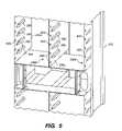
- FIG. 5is an enlarged perspective view of a central portion of the front section of the computer system 200 .
- front and rearare used to describe various components in the illustrated computer system 200 , it will be understood that these are relative terms used here for convenience.
- the front section of the computer system 200 and the rear section of the computer system 200are substantially identical, but oriented in opposite directions so that the front sides 601 of the computers 210 mounted in the front section can be accessed through the front opening 212 , and the front sides 601 of the computers 210 mounted in the rear section can be accessed through the rear opening 214 .
- the following textdescribes the front portion of the computer system 200 . However, it will be understood that the description may apply to the rear portion as well.
- FIGS. 6A-6Bare front perspective views of a computer 210 that can be mounted into the rack assembly 201 .
- the computer 210may comprise a computer chassis 600 containing a main board 610 and other components, such as one or more power supplies 612 , hard drives 608 , removable media drives 609 , processors 624 , and expansion cards, contained within the computer chassis 600 .
- the chassis 600may comprise a chassis top 602 , which may be removable to provide access to the components contained therein.
- An exemplary computer 210is described in greater detail in the following U.S. provisional patent applications: U.S. provisional patent application No. 60/569,025, entitled “RACK MOUNTED COMPUTER SYSTEM”, filed May 7, 2004; U.S. provisional patent application No.
- a computer 210may comprise any electronic system designed to perform computations and/or data processing.
- the computer 210comprises an electronic device having a central processing unit (CPU) and memory.
- the CPU and memorymay be provided on a main board 610 , which, in turn, may be mounted to the computer chassis 600 .
- the basic circuitry and components used by a computer to functionare generally either contained in or attached to the main board.
- the main boardtypically contains the system bus, processor and coprocessor sockets, memory sockets, serial and parallel ports, expansion slots, and peripheral controllers.
- This chassis 600may comprise, for example, a housing that encloses all or portions of the main board 610 and components coupled thereto.
- the chassis 600may comprise a minimal structure (such as, e.g., a tray or frame) which provides mechanical support for the main board 610 .
- the computermay comprise a printed circuit board (PCB) main board having exposed components without an enclosure.
- PCBprinted circuit board
- FIG. 6Bis a perspective view of the front side 601 of the computer 210 with the chassis top 602 removed to expose the main board 630 and other components contained within the computer chassis 600 .
- the front sides 601 of the computers 210are exposed to a user facing the front opening 212 of the rack assembly 201 .
- the front side 601 of the computer 210exposes various components which a user may wish to access to operate or maintain the computer system 200 . These components may include, for example, one or more removable media drive ports, a mass storage device, and I/O connectors.
- the computer 210may be provided with a front bezel which partially or fully covers the front of the computer 210 .
- This bezelmay be removable or pivotally mounted to enable the bezel to be opened to provide access to the various components.
- the bezelmay function to reduce the effect of electromagnetic interference (EMI), to minimize the impact of environmental factors, and to improve the aesthetic appearance of the computer 210 .
- EMIelectromagnetic interference
- the I/O connectorsare exposed by an I/O connector opening 618 in the computer chassis 600 .
- the I/O connector opening 618is covered by a movable I/O door 620 , which provides EMI shielding.
- FIG. 7is a perspective view of the rear side 603 of the computer 210 .
- the rear side 603 of the computer chassis 600may comprise a directional fan assembly 640 , a power port opening 632 for exposing a power connector of a power supply 612 , a power switch opening 634 , a power supply fan opening 636 , and a chassis connector 650 .
- the rear side 603may also include one or more additional apertures to accommodate other components, such as additional fans or I/O connectors, which may be added to alternative designs of the computer 210 .
- the main board 630includes a plurality of I/O connectors mounted to a top surface of the printed circuit board forming the main board 630 .
- the types of I/O connectorsmay vary depending on the main board and chipset configuration, but may include, for example, one or more network connectors 660 a - 660 c (shown in this embodiment as female RJ-45 connectors), a video port 662 , a SCSI port 664 , a USB port 666 , and a serial port 668 .
- the I/O connectorsmay further include, for example, IEEE 1394 ports, parallel ports, and mouse and/or keyboard ports, such as AT or PS/2 connectors.
- the main board 630may be a standard, “off-the-shelf” main board designed for use in conventional computer systems. Accordingly, the I/O connectors are positioned along the edge of the main board 630 such that when the main board is installed in a conventional computer chassis, the I/O connectors are flush or nearly flush with the side of the computer chassis.
- the computer chassiswould include an opening containing an I/O shield that exposes the I/O connectors, This enables a user to connect the I/O cables to the I/O connectors after the computer has been mounted in the rack.
- a connector grouping assembly 800may be used to facilitate I/O connections between the computer 210 and other components in the rack assembly 201 .
- FIG. 8is a simplified block diagram illustrating an arrangement for a computer 210 mounted in the rack assembly 201 . It will be understood that similar arrangements may be utilized for the other computers 210 in the rack assembly 201 .
- the computer 210is supported by the side panels 204 a - 204 b of the rack assembly 201 .
- the chassis connector 650 mounted to the rear side 603 of the computer chassis 600is coupled to the proximal end of one or more I/O cables, shown in FIG. 8 as three I/O cables 652 a - 652 c .
- the distal ends of these I/O cables 652 a - 652 cmay, in turn, be coupled to one or more I/O connectors on the main board 630 .
- FIG. 8the chassis connector 650 mounted to the rear side 603 of the computer chassis 600 is coupled to the proximal end of one or more I/O cables, shown in FIG. 8 as three I/O cables 652 a - 652 c .
- the distal ends of these I/O cables 652 a - 652 cmay, in turn, be coupled to one or more I/O connectors on the main board 630 .
- two of the I/O cables 652 a - 652 bcomprise two male RJ-45 network cables that are coupled with two of the female RJ-45 I/O connectors 660 a - 660 b
- a third I/O cable 652 ccomprises a serial cable coupled to a serial connector 661 mounted elsewhere on the main board 630 .
- This arrangementfacilitates the electrical coupling of multiple I/O connectors 660 a - 660 c on the main board 630 with a single chassis connector 650 mounted to the computer chassis 600 .
- the chassis connector 650is positioned such that when the computer 210 is fully inserted into an available bay of the rack assembly 201 , the chassis connector 650 mates with a rack I/O connector 672 of a blind mate I/O interface assembly 670 , which is mounted to the rear support 234 of the rack assembly 201 .
- a power cable 678may also be retained by the rear support 234 such that as the computer 210 is inserted into the rack assembly 201 and the chassis connector 650 mates with the rack I/O connector 672 , the power cable 678 will also mate with a power connector of the power supply 612 on the computer 210 . In this way, both data and power connectivity to the computer 210 may be provided by simply inserting the computer 210 into the rack assembly 201 .
- FIGS. 9A-9Bshow front and back perspective views of an exemplary I/O interface assembly 670 .
- the I/O interface assembly 670comprises a printed circuit board 674 having the rack I/O connector 672 mounted to a front side and a plurality of I/O connectors 676 (shown as female RJ-45 connectors) mounted to a back side. In other embodiments, different quantities and types of connectors may be used.
- the PCB 674provides the electrical connection between the contacts of the rack I/O connector 672 and the contacts of the I/O connectors 676 .
- a plurality of similar I/O interface assemblies 670may be fixedly coupled to each of the rear supports 234 of the rack assembly 201 to provide electrical connections to the chassis connectors 650 of each of the computers 210 mounted in the rack assembly 201 .
- FIG. 10shows a perspective view of a back sides of a plurality of computers 210 ′ fully inserted into the rack assembly 201 ′, in accordance with another embodiment of the present invention.
- the I/O connectors 676 ′ of the I/O interface assembly 670 ′protrude from the back side of the rear support 234 ′.
- I/O cablescan be mated with these I/O connectors 676 ′ to connect the connectors 676 ′ with other components in the rack assembly 201 , such as a switch or hub. Alternatively, these cables can be coupled with a component located outside of the rack assembly 201 .
- FIG. 10shows a perspective view of a back sides of a plurality of computers 210 ′ fully inserted into the rack assembly 201 ′, in accordance with another embodiment of the present invention.
- the I/O connectors 676 ′ of the I/O interface assembly 670 ′protrude from the back side of the rear support 234 ′.
- I/O cablescan be
- a flange 679may be used to provide support for the power cable 678 ′ (only partially shown in FIG. 10 ). Because the insertion force necessary to mate the power cable 678 ′ with the power connector on the computer 210 may be fairly large, the flange 679 may be used to ensure that the power cable 678 ′ is retained in place during mating.
- a gapmay be provided between the edge of the main board 630 and the side of the computer chassis 600 .
- This gapprovides clearance for the I/O cables 652 to be plugged into the I/O connectors 660 and then routed towards the rear side 603 of the computer chassis 600 .
- This change of direction for the cables 652can be accomplished without having the cables 652 protrude from the front of the computer chassis 600 .
- the cables 652may be fully contained within the computer chassis 600 such that they are only accessible by removing the chassis top 602 or by opening the I/O door 620 . This can help to manage the number of cables in the computer system 200 and reduce the number of dangling cables in the rack assembly 201 .
- these cables 652may be routed to the rear side 603 and may terminate at the chassis connector 650 .
- the chassis connector 650may comprise a coupling device which provides an electrical and mechanical connection to the corresponding rack connector 672 .
- the chassis connector 650 and rack connector 672may comprise plastic housings having metal conductors provided therein which provide electrical connectivity between the connectors 650 , 672 when the connectors 650 , 672 are mated.
- the chassis connector 650may be mounted on the rear side wall of the computer chassis 600 such that one end of the chassis connector 650 is exposed to the interior of the computer chassis 600 and is coupled to the cables 652 , and the other end is exposed to the exterior of the computer chassis 600 to be blind mated with the rack connector 672 .
- the two connectors 650 , 672may bridge the gap in an electrical or fiber optic circuit.
- the chassis connector 650comprises a Micro-Fit 3.0, BMITM Panel-to-Panel Receptacle, part no. 44133
- the rack connector 672comprises a Micro-Fit 3.0, BMITM Panel-to-Panel Plug, part no. 44300, both by Molex, Inc., of Lisle, Ill.
- different types of connectorsmay be used.
- the rack connector 672comprises a female connector and the chassis connector 650 comprises a male connector.
- the female rack connector 672may include sloped surfaces 677 that can help to guide the male chassis connector 650 to accurately mate with the female connector 672 when the two connectors 650 , 672 are not perfectly aligned during insertion of the computer 210 .
- different types of connector designsmay be used.
- Embodiments of the present inventionmay provide a cable management solution that enables blind mating of I/O connectors in a rack-based computer system in conjunction with standard main board and chipset designs. Embodiments may also provide a computer chassis and rack system design which can be utilized with a variety of main board configurations.
- Embodiments of the present inventionmay be used for connecting the I/O connectors on any main board design to a single blind mating connector using flexible cables that can be coupled to connectors located anywhere in the computer 210 .
- the rack assemblymay be used in conjunction with a variety of main boards, regardless of the precise locations of the I/O connectors.
- the embodiments described abovemay enable a low cost, industry standard, “off-the-shelf” main board to be used in a computer system, while providing some of the advantages of “blade”-type systems.
- data and power connectivity with the computer 210may be obtained by simply inserting the computer 210 into an available bay in the rack assembly 201 .
- no additional cable attachmentsare needed for operation of the computer system 200 .
- Thiscan also improve serviceability of the computers 210 .
- the operatormay need to disconnect multiple network and power cables before removing a computer from a rack assembly.
- the network and power connectionscan be automatically disconnected by simply withdrawing the computer 210 from the rack assembly 201 . This can facilitate rapid maintenance and/or replacement of the computers 210 .
- the I/O connectors 676 of the I/O interface assembly 670are mounted to the rack assembly 201 and not the computer chassis 600 , the I/O cables connected to the I/O connectors 676 can remain connected to the I/O connectors 676 even after the computer 210 is removed from the rack assembly 201 . This can help to reduce the labor required to manage the various cables of the computer system 200 .
- the precise locations of the I/O connectors 660are not limiting.
- the I/O connectors 660may be located anywhere in the computer 210 , and the cables 652 can still be used to couple the I/O connectors 660 to the chassis connector 650 . It is not necessary to have a custom-designed motherboard, such as those used in conventional “blade” systems.
- a computer manufacturermay use the same chassis design with different main board layouts, thus allowing a single chassis and rack assembly design to be used with a variety of different computer types.
- the I/O connectors 676 on the I/O interface assembly 670may be identical to the I/O connectors 660 located at the front section of the computer 210 , thereby enabling the same cables which would have been coupled with the I/O connectors 660 in the computer 210 to be connected to the I/O connectors 676 on the I/O interface assembly 670 . This may facilitate the use of more standard “off-the-shelf” components in the computer system, thereby decreasing overall costs.
- an optional location pinmay be provided on the computer chassis for mating with a location hole on the rack assembly.
- the location pinmay be used to provide a datum for consistently and accurately mounting the computer 210 in the rack assembly 201 .
- the location pinmay be sized such that the location pin mates with the location hole before the I/O connector on the computer 210 reaches the I/O connector on the rack assembly 201 . This ensures that the computer 210 is properly aligned with the rack assembly 201 so that the I/O connectors will reliably mate each time that the computer 210 is inserted into the rack assembly 201 .
- the I/O connectors 660 a - 660 bcomprise RJ-45 network connectors.
- the connectors which are coupled to the chassis connector 650 via cables 652may comprise other types of data and/or power connectors, such as, e.g., SCS1, fibre channel, USB, and the like.
- the cables 652 coupling the connectors on the main board 630 with the chassis connector 650may vary in number and type.
- two of the cables 652may be network cables coupled to RJ-45 network ports and a third cable 652 coupled to a serial port.
- the two I/O connectors 660 a - 660 bmay comprise, for example, gigabit NICs.
- one of the cables 652may be coupled to a network port, one of the cables 652 may be coupled to a USB port, and one of the cables 652 may be left uncoupled and reserved for potential future use.
- a plurality of extra cables 652 having one or more different interface typesmay be provided for potential future use.
- the cables 652may be bundled together or separated. It may be desirable to bundle all of the cables 652 together when the connectors to which the cables 652 are intended to be coupled are closely spaced on the main board. This can help to reduce the cable clutter within the computer chassis and improve cooling airflow therethrough. In other embodiments, it may be desirable to have one or more of the cables 652 partially or fully separated from the other cables 652 so that each cable 652 can be easily routed to couple with connectors positioned at distal locations on the main board.
- a single chassis connector 650is mounted to the back side of the computer 210 and is coupled to multiple cables 652 a - 652 c .
- multiple chassis connectorsmay be mounted to the back side of the computer, each of the chassis connectors being coupled to one or more cables.
- Each of these chassis connectorscan be used to electrically couple a connector on the main board with a corresponding rack connector on the rack assembly. Because the chassis connectors are mounted either directly or indirectly to the computer chassis, the chassis connector can be blind mated with the rack connector using the insertion force provided to insert the computer into the bay of the rack assembly.
- the arrangement of computers 210 in the rack assembly 201may vary.
- the illustrated systemincludes four stacks of computers 210 arranged side-by-side and back-to-back, in other embodiments, the computers 210 may be arranged differently.
- the computersmay be arranged in a single stack, as is commonly used in the industry.
- the computersmay be vertically oriented, as opposed to the horizontally-oriented computers 210 shown in the figures.
- the computersmay have different form factors (e.g., some computers have a 1U profile, while others have a 2U or 3U profile) and may be configured to perform different tasks (e.g., one or more computers may be configured as a central controllers, while other computers in the stack may be configured as storage arrays).
Landscapes
- Engineering & Computer Science (AREA)
- Computer Hardware Design (AREA)
- General Engineering & Computer Science (AREA)
- Microelectronics & Electronic Packaging (AREA)
- Cooling Or The Like Of Electrical Apparatus (AREA)
Abstract
Description
Claims (9)
Priority Applications (3)
| Application Number | Priority Date | Filing Date | Title |
|---|---|---|---|
| US11/125,941US7460375B2 (en) | 2004-05-07 | 2005-05-09 | Interface assembly |
| US12/263,311US7692928B2 (en) | 2004-05-07 | 2008-10-31 | Interface assembly |
| US12/726,299US7924570B2 (en) | 2004-05-07 | 2010-03-17 | Interface assembly |
Applications Claiming Priority (5)
| Application Number | Priority Date | Filing Date | Title |
|---|---|---|---|
| US56902504P | 2004-05-07 | 2004-05-07 | |
| US56896904P | 2004-05-07 | 2004-05-07 | |
| US56901904P | 2004-05-07 | 2004-05-07 | |
| US56902004P | 2004-05-07 | 2004-05-07 | |
| US11/125,941US7460375B2 (en) | 2004-05-07 | 2005-05-09 | Interface assembly |
Related Child Applications (1)
| Application Number | Title | Priority Date | Filing Date |
|---|---|---|---|
| US12/263,311ContinuationUS7692928B2 (en) | 2004-05-07 | 2008-10-31 | Interface assembly |
Publications (2)
| Publication Number | Publication Date |
|---|---|
| US20050286235A1 US20050286235A1 (en) | 2005-12-29 |
| US7460375B2true US7460375B2 (en) | 2008-12-02 |
Family
ID=35505442
Family Applications (3)
| Application Number | Title | Priority Date | Filing Date |
|---|---|---|---|
| US11/125,941Active2026-06-12US7460375B2 (en) | 2004-05-07 | 2005-05-09 | Interface assembly |
| US12/263,311Expired - LifetimeUS7692928B2 (en) | 2004-05-07 | 2008-10-31 | Interface assembly |
| US12/726,299Expired - LifetimeUS7924570B2 (en) | 2004-05-07 | 2010-03-17 | Interface assembly |
Family Applications After (2)
| Application Number | Title | Priority Date | Filing Date |
|---|---|---|---|
| US12/263,311Expired - LifetimeUS7692928B2 (en) | 2004-05-07 | 2008-10-31 | Interface assembly |
| US12/726,299Expired - LifetimeUS7924570B2 (en) | 2004-05-07 | 2010-03-17 | Interface assembly |
Country Status (1)
| Country | Link |
|---|---|
| US (3) | US7460375B2 (en) |
Cited By (18)
| Publication number | Priority date | Publication date | Assignee | Title |
|---|---|---|---|---|
| US20090086441A1 (en)* | 2004-05-07 | 2009-04-02 | Rackable Systems, Inc. | Interface assembly |
| US20090141441A1 (en)* | 2007-12-03 | 2009-06-04 | Sun Microsystems, Inc. | Air baffle with integrated tool-less expansion card attachment |
| US20090152216A1 (en)* | 2007-12-13 | 2009-06-18 | International Business Machines Corporation | Rack system providing flexible configuration of computer systems with front access |
| US20090250236A1 (en)* | 2008-04-07 | 2009-10-08 | Kickfire, Inc. | Flexible mechanical packaging form factor for rack mounted computing devices |
| US20090257187A1 (en)* | 2008-04-11 | 2009-10-15 | Dell Products L.P. | Information Handling System with Chassis Design for Storage Device Access |
| US20100064059A1 (en)* | 2008-09-08 | 2010-03-11 | Limo Lu | Modularized electronic switching controller assembly for computer |
| US20110026215A1 (en)* | 2009-07-28 | 2011-02-03 | Lin Te-Chang | Server module |
| US20110043986A1 (en)* | 2008-04-30 | 2011-02-24 | Conn Kevin D | Power supply assembly for server rack and method for mounting power supply for server rack |
| US8029320B1 (en)* | 2010-11-15 | 2011-10-04 | Intel Corporation | Integrated module including physical layer network device, receptacle and physical layer isolation module |
| US20120008285A1 (en)* | 2010-07-06 | 2012-01-12 | Renkel Jr Leonard R | Rear Cover and Input/Output Panels |
| US20120036322A1 (en)* | 2010-08-06 | 2012-02-09 | David Harry Klein | Raid devices, systems, and methods |
| US20130021756A1 (en)* | 2011-07-21 | 2013-01-24 | Hon Hai Precision Industry Co., Ltd. | Data center with cable management structure |
| US20130163198A1 (en)* | 2011-12-24 | 2013-06-27 | Hon Hai Precision Industry Co., Ltd. | Server assembly and rack of the same |
| US20140268528A1 (en)* | 2013-03-14 | 2014-09-18 | Rackspace Us, Inc. | Rack adapter apparatus and method |
| US20150255902A1 (en)* | 2010-05-07 | 2015-09-10 | Dell Products L.P. | Processor loading system |
| US9996123B1 (en)* | 2017-08-10 | 2018-06-12 | Aic Inc. | Computer device |
| US11924992B1 (en)* | 2022-08-31 | 2024-03-05 | Dell Products L.P. | Rack front-to-rear cable routing system |
| US20240125327A1 (en)* | 2017-06-08 | 2024-04-18 | Q-PAC Systems Inc. | Fan array wiring system |
Families Citing this family (91)
| Publication number | Priority date | Publication date | Assignee | Title |
|---|---|---|---|---|
| US20060092604A1 (en)* | 2004-11-01 | 2006-05-04 | Bang-Heng Ting | Computer reader mounting device |
| US20070099493A1 (en)* | 2005-11-02 | 2007-05-03 | Eren Niazi | Vertical patch panel |
| US7408784B2 (en)* | 2005-11-04 | 2008-08-05 | Dedicated Devices, Inc. | Computer chassis assembly |
| US7427713B2 (en)* | 2006-03-13 | 2008-09-23 | Panduit Corp. | Network cabinet |
| US7795532B2 (en)* | 2006-03-13 | 2010-09-14 | Panduit Corp. | Network Cabinet |
| US9426903B1 (en) | 2008-06-27 | 2016-08-23 | Amazon Technologies, Inc. | Cooling air stack for computer equipment |
| US8783336B2 (en) | 2008-12-04 | 2014-07-22 | Io Data Centers, Llc | Apparatus and method of environmental condition management for electronic equipment |
| US8733812B2 (en)* | 2008-12-04 | 2014-05-27 | Io Data Centers, Llc | Modular data center |
| US20100217909A1 (en)* | 2009-02-24 | 2010-08-26 | Sun Microsystems, Inc. | Field replaceable unit for solid state drive system |
| US8630087B1 (en)* | 2009-10-22 | 2014-01-14 | Juniper Networks, Inc. | Airflow system, cable access system, and cable management system based on midplane having holes, side access of chassis, and card configuration |
| US8116082B2 (en)* | 2009-11-17 | 2012-02-14 | Telefonaktiebolaget L M Ericsson (Publ) | Fan tray that is installable and removable from the front and back of a network element chassis |
| DE102009057272A1 (en)* | 2009-12-08 | 2011-06-09 | Diehl Bgt Defence Gmbh & Co. Kg | Electronic module |
| US9220180B2 (en)* | 2010-12-09 | 2015-12-22 | Richard Anthony Dunn, JR. | System and methods for scalable parallel data processing and process control |
| US20110176270A1 (en)* | 2010-01-19 | 2011-07-21 | Ku-Yang Chou | System rack for accessing hard disks in dual directions |
| US9710595B2 (en)* | 2010-02-24 | 2017-07-18 | International Business Machines Corporation | Multi-view user interface for server cabling display |
| US8638553B1 (en) | 2010-03-31 | 2014-01-28 | Amazon Technologies, Inc. | Rack system cooling with inclined computing devices |
| US8755192B1 (en)* | 2010-03-31 | 2014-06-17 | Amazon Technologies, Inc. | Rack-mounted computer system with shock-absorbing chassis |
| US9894808B2 (en) | 2010-03-31 | 2018-02-13 | Amazon Technologies, Inc. | Compressed air cooling system for data center |
| US9622387B1 (en) | 2010-03-31 | 2017-04-11 | Amazon Technologies, Inc. | Rack-mounted air directing device with scoop |
| US8369092B2 (en)* | 2010-04-27 | 2013-02-05 | International Business Machines Corporation | Input/output and disk expansion subsystem for an electronics rack |
| US20110266229A1 (en)* | 2010-04-30 | 2011-11-03 | M&A Technology, Inc. | Stackable modular personal computer array |
| CN102289268A (en)* | 2010-06-17 | 2011-12-21 | 英业达股份有限公司 | rack server |
| KR101004314B1 (en) | 2010-07-09 | 2010-12-27 | 주식회사 한진이엔씨 | Front panel for preventing confusion of mounting parts of traffic signal controller |
| US8687349B2 (en)* | 2010-07-21 | 2014-04-01 | Teradyne, Inc. | Bulk transfer of storage devices using manual loading |
| US8477491B1 (en) | 2010-09-20 | 2013-07-02 | Amazon Technologies, Inc. | System with rack-mounted AC fans |
| US8416565B1 (en) | 2010-09-20 | 2013-04-09 | Amazon Technologies, Inc. | Bracket for rack mounted power distribution unit |
| US8400765B2 (en)* | 2010-09-20 | 2013-03-19 | Amazon Technologies, Inc. | System with air flow under data storage devices |
| US8472183B1 (en) | 2010-09-20 | 2013-06-25 | Amazon Technologies, Inc. | Rack-mounted computer system with front-facing power supply unit |
| US10492331B1 (en) | 2010-09-29 | 2019-11-26 | Amazon Technologies, Inc. | System and method for cooling power distribution units |
| US8674218B2 (en)* | 2010-12-15 | 2014-03-18 | General Electric Company | Restraint system for an energy storage device |
| US9072191B2 (en)* | 2010-12-30 | 2015-06-30 | Schneider Electric It Corporation | Configurable rack and related methods |
| US9055690B2 (en)* | 2011-03-22 | 2015-06-09 | Amazon Technologies, Inc. | Shelf-mounted modular computing unit |
| TW201306695A (en)* | 2011-07-26 | 2013-02-01 | Hon Hai Prec Ind Co Ltd | Data center |
| US20140297180A1 (en)* | 2011-11-15 | 2014-10-02 | John Minjae Cho | Mobilized Sensor System |
| CN103139106B (en)* | 2011-11-28 | 2014-06-11 | 英业达科技有限公司 | Server rack system |
| US9095070B2 (en) | 2011-12-05 | 2015-07-28 | Amazon Technologies, Inc. | Partial-width rack-mounted computing devices |
| US8720043B2 (en) | 2011-12-15 | 2014-05-13 | Amazon Technologies, Inc. | Method of allocating resources in a rack system |
| US8773861B2 (en) | 2011-12-15 | 2014-07-08 | Amazon Technologies, Inc. | Reconfigurable shelf for computing modules |
| US8867214B2 (en) | 2011-12-15 | 2014-10-21 | Amazon Technologies, Inc. | Modular server design for use in reconfigurable server shelf |
| WO2013112858A1 (en) | 2012-01-27 | 2013-08-01 | Go!Foton Holdings, Inc. | Patch panel assembly |
| US10123464B2 (en) | 2012-02-09 | 2018-11-06 | Hewlett Packard Enterprise Development Lp | Heat dissipating system |
| US9008484B2 (en) | 2012-03-28 | 2015-04-14 | Go!Foton Holdings, Inc. | Optical switch |
| GB2502316A (en)* | 2012-05-24 | 2013-11-27 | Ibm | Blade enclosure with interfaces for computer blades and conventional computers |
| US8925739B2 (en)* | 2012-07-26 | 2015-01-06 | Lenovo Enterprise Solutions (Singapore) Pte. Ltd. | High-capacity computer rack with rear-accessible side bays |
| US10082857B1 (en) | 2012-08-07 | 2018-09-25 | Amazon Technologies, Inc. | Cooling electrical systems based on power measurements |
| US8966821B2 (en) | 2012-09-14 | 2015-03-03 | Panduit Corp. | Dual hinged door mechanism |
| CN103677179A (en)* | 2012-09-21 | 2014-03-26 | 英业达科技有限公司 | Server |
| JP6112640B2 (en) | 2012-09-28 | 2017-04-12 | ヒューレット パッカード エンタープライズ デベロップメント エル ピーHewlett Packard Enterprise Development LP | Cooling assembly |
| TWI491347B (en)* | 2012-10-24 | 2015-07-01 | Hon Hai Prec Ind Co Ltd | Cooling plate and enclosing casing |
| BR112015018354A2 (en) | 2013-01-31 | 2017-07-18 | Hewlett Packard Development Co | liquid cooling |
| US9894809B1 (en) | 2013-02-28 | 2018-02-13 | Amazon Technologies, Inc. | System for supplying cooling air from sub-floor space |
| US9728945B2 (en)* | 2013-03-13 | 2017-08-08 | Go!Foton Holdings, Inc. | Patch panel assembly |
| US9392720B1 (en)* | 2013-03-13 | 2016-07-12 | Google Inc. | Server rack architecture that facilitates reduced current density |
| JP5765356B2 (en)* | 2013-03-19 | 2015-08-19 | 株式会社安川電機 | Enclosure |
| US10037061B1 (en) | 2013-04-30 | 2018-07-31 | Amazon Technologies, Inc. | Multiple-stage cooling system for rack |
| US9462356B2 (en) | 2013-05-29 | 2016-10-04 | Go!Foton Holdings, Inc. | Patch panel assembly |
| US9344776B2 (en) | 2013-05-29 | 2016-05-17 | Go!Foton Holdings, Inc. | Patch panel tray assembly |
| US9581781B2 (en) | 2013-06-24 | 2017-02-28 | Go!Foton Holdings, Inc. | Patch panel pivoting tray cable retention mechanisms |
| JP6229361B2 (en)* | 2013-08-01 | 2017-11-15 | 富士通株式会社 | Electronic equipment and board unit |
| US9141156B2 (en) | 2013-08-02 | 2015-09-22 | Amazon Technologies, Inc. | Compute node cooling with air fed through backplane |
| US10222842B2 (en) | 2013-08-02 | 2019-03-05 | Amazon Technologies, Inc. | System for compute node maintenance with continuous cooling |
| CN104423457A (en)* | 2013-09-11 | 2015-03-18 | 鸿富锦精密电子(天津)有限公司 | Electronic device and fixing rack thereof |
| ITRM20130540A1 (en)* | 2013-10-04 | 2015-04-05 | Ecm S P A | PERIPHERAL PLACE OF CONTROL OF RAILWAY CENTERS OF PLANT AND METHOD OF INSTALLATION OF SUCH PERIPHERAL PLACE |
| CN104955286A (en)* | 2014-03-27 | 2015-09-30 | 鸿富锦精密电子(天津)有限公司 | Cabinet |
| US9635776B2 (en)* | 2014-04-25 | 2017-04-25 | Hong Fu Jin Precision Industry (Shenzhen) Co., Ltd. | Cabinet |
| US9795050B2 (en) | 2014-05-22 | 2017-10-17 | Super Micro Computer Inc. | Server capable of accessing and rotating storage devices accommodated therein |
| TWM488170U (en)* | 2014-05-22 | 2014-10-11 | Super Micro Computer Inc | Server chassis capable of rotating and loading storage device |
| WO2016018417A1 (en)* | 2014-07-31 | 2016-02-04 | Hewlett-Packard Development Company, L.P. | Backup power assembly having blind mate connector |
| US9713279B2 (en)* | 2014-12-30 | 2017-07-18 | Quanta Computer Inc. | Front access server |
| US9491884B2 (en)* | 2015-01-15 | 2016-11-08 | Aic Inc. | Server cabinet drawer structure |
| US9441762B2 (en) | 2015-01-28 | 2016-09-13 | Go!Foton Holdings, Inc. | Cable guide apparatus |
| US9924611B2 (en)* | 2015-05-15 | 2018-03-20 | Innovation First, Inc. | Connectors to secure multiple rails in a server rack |
| DE202015009727U1 (en)* | 2015-05-29 | 2019-08-02 | Connect Com GmbH | distribution cabinet |
| CN105142040B (en)* | 2015-08-31 | 2018-08-03 | 深圳日海通讯技术股份有限公司 | The load module of optical fiber cable |
| US10624241B1 (en) | 2015-10-06 | 2020-04-14 | Amazon Technologies, Inc. | Rack mountable thermal regulation system |
| US10368466B1 (en) | 2015-10-06 | 2019-07-30 | Amazon Technologies, Inc. | Rack mountable cooling canister |
| US9642286B1 (en) | 2015-12-14 | 2017-05-02 | Amazon Technologies, Inc. | Coordinated control using rack mountable cooling canisters |
| US10321608B1 (en) | 2015-12-14 | 2019-06-11 | Amazon Technologies, Inc. | Coordinated cooling using rack mountable cooling canisters |
| JP2018010845A (en)* | 2016-07-15 | 2018-01-18 | 富士通株式会社 | Electronic device, contactor, and electronic device system |
| US10034407B2 (en)* | 2016-07-22 | 2018-07-24 | Intel Corporation | Storage sled for a data center |
| TWI586249B (en)* | 2016-08-18 | 2017-06-01 | 緯創資通股份有限公司 | Server device |
| US9861002B1 (en)* | 2016-10-20 | 2018-01-02 | Rockwell Automation Technologies, Inc. | Single channel I/O in a modular sub-chassis |
| US10291969B2 (en) | 2017-02-14 | 2019-05-14 | Go!Foton Holdings, Inc. | Rear cable management |
| US20190021178A1 (en)* | 2017-07-14 | 2019-01-17 | Panduit Corp. | Faux Column Intermediate Distribution Frame Enclosure |
| US10765026B2 (en)* | 2018-08-17 | 2020-09-01 | Microsoft Technology Licensing, Llc | Automated data center |
| CN114667033A (en)* | 2019-03-14 | 2022-06-24 | 华为技术有限公司 | Heat dissipation method, heat dissipation device and cabinet |
| US11212941B2 (en)* | 2020-06-01 | 2021-12-28 | Astec International Limited | Equipment shelf |
| US11303074B2 (en)* | 2020-06-22 | 2022-04-12 | Google Llc | Enclosures to constrain the location of connectors in automation applications |
| EP3971622A1 (en) | 2020-07-02 | 2022-03-23 | Go!Foton Holdings, Inc. | Intelligent optical switch |
| USD989749S1 (en)* | 2021-02-03 | 2023-06-20 | Sonos, Inc. | Audio device rack mount |
| CN114661109B (en)* | 2022-03-25 | 2023-04-28 | 苏州浪潮智能科技有限公司 | Multipath cross-node signal interconnection structure |
Citations (33)
| Publication number | Priority date | Publication date | Assignee | Title |
|---|---|---|---|---|
| US3925710A (en)* | 1974-07-01 | 1975-12-09 | Us Navy | General purpose electronic interface equipment package |
| US5202536A (en) | 1992-02-03 | 1993-04-13 | Schlegel Corporation | EMI shielding seal with partial conductive sheath |
| US5347430A (en) | 1993-04-06 | 1994-09-13 | Dell Usa, L.P. | Computer chassis construction |
| US5351176A (en) | 1992-12-31 | 1994-09-27 | North Atlantic Industries, Inc. | Panel for a computer including a hinged door with integral display |
| US5460441A (en) | 1994-11-01 | 1995-10-24 | Compaq Computer Corporation | Rack-mounted computer apparatus |
| US5684271A (en) | 1994-07-14 | 1997-11-04 | Dell Usa, L.P. | Configurationally variable computer chassis/EMI shield apparatus and associated fabrication methods |
| US5726866A (en) | 1996-02-14 | 1998-03-10 | Compaq Computer Corporation | Slide out readily accessible chassis having a trough for protecting cables and a hinge that includes a conduit |
| US6163454A (en) | 1999-02-22 | 2000-12-19 | Hewlett-Packard Company | Electromagnetic interference (EMI) shield for electrical components, an internal EMI barrier, and a storage enclosure for electrical/electronic components |
| US6215659B1 (en) | 1999-10-12 | 2001-04-10 | Hon Hai Precision Ind. Co., Ltd. | Fan housing in a computer enclosure |
| US6252160B1 (en) | 1998-05-08 | 2001-06-26 | Hon Hai Precision Ind. Co., Ltd. | I/O shield for electronic assemblies |
| US20020006026A1 (en)* | 1999-05-31 | 2002-01-17 | Tsutomu Takahashi | Communications apparatus and plug-in unit |
| US6349042B1 (en) | 2000-03-24 | 2002-02-19 | Dell Products L.P. | Apparatus for shielding electromagnetic emissions |
| US6414851B2 (en) | 1999-05-18 | 2002-07-02 | Hewlett-Packard Co. | Computer system housing for attenuating electromagnetic interference (EMI) |
| US20020109971A1 (en)* | 2000-08-22 | 2002-08-15 | Force Computers, Inc. | Add-on cable feed-through device for computer chassis |
| US6477061B1 (en) | 1998-03-23 | 2002-11-05 | Amesbury Group, Inc. | I/O port EMI shield |
| US6480398B1 (en) | 2000-01-05 | 2002-11-12 | Compaq Computer Corporation | CPU easy access panels |
| US6482046B1 (en) | 2001-08-21 | 2002-11-19 | Compaq Information Technologies Group, L.P. | Cable coupler |
| US6496366B1 (en) | 1999-10-26 | 2002-12-17 | Rackable Systems, Llc | High density computer equipment storage system |
| US6512673B1 (en) | 2000-07-05 | 2003-01-28 | Network Engines, Inc. | Low profile equipment housing with angular fan |
| US6560114B2 (en) | 2001-06-29 | 2003-05-06 | Intel Corporation | Rack-mounted server and associated methods |
| US20030124971A1 (en) | 2000-03-07 | 2003-07-03 | Williams John Williamson | Computers with power exhaust systems |
| US20030128516A1 (en) | 2002-01-04 | 2003-07-10 | Faneuf Barrett M. | Frame-level thermal interface component for transfer of heat from an electronic component of a computer system |
| US6594150B2 (en)* | 2000-02-02 | 2003-07-15 | Sun Microsystems, Inc. | Computer system having front and rear cable access |
| US6611432B2 (en) | 2001-01-26 | 2003-08-26 | Dell Products L.P. | Docking bracket for rack-mounted computing modules |
| US6621000B2 (en) | 2001-08-21 | 2003-09-16 | Dell Products L.P. | Perforated EMI gasket |
| US20030223193A1 (en)* | 2002-05-31 | 2003-12-04 | Racksaver, Inc. | Method and apparatus for rack mounting computer components |
| US20040057216A1 (en)* | 2002-09-25 | 2004-03-25 | Smith John V. | Electronic component rack assembly and method |
| US6762934B2 (en) | 2001-08-10 | 2004-07-13 | Sun Microsystems, Inc. | Module ejection mechanism |
| US6796833B2 (en) | 2001-10-31 | 2004-09-28 | Hewlett-Packard Development Company, L.P. | Multi-server, quick swap rack frame wih consolidated power distribution, integrated keyboard/video/mouse concentrator and, USB hub |
| US6862173B1 (en) | 2002-07-11 | 2005-03-01 | Storage Technology Corporation | Modular multiple disk drive apparatus |
| US20050265004A1 (en) | 2004-05-07 | 2005-12-01 | Giovanni Coglitore | Rack mounted computer system |
| US7136283B2 (en)* | 2003-06-11 | 2006-11-14 | Hewlett-Packard Development Company, L.P. | Multi-computer system |
| US7236358B2 (en)* | 2003-06-11 | 2007-06-26 | Hewlett-Packard Development Company, L.P. | Computer system |
Family Cites Families (19)
| Publication number | Priority date | Publication date | Assignee | Title |
|---|---|---|---|---|
| US5251097A (en)* | 1990-06-11 | 1993-10-05 | Supercomputer Systems Limited Partnership | Packaging architecture for a highly parallel multiprocessor system |
| CA2124773C (en)* | 1994-05-31 | 1998-11-03 | Raymond Bruce Wallace | Backplane and shelf |
| TW265430B (en)* | 1994-06-30 | 1995-12-11 | Intel Corp | Ducted opposing bonded fin heat sink blower multi-microprocessor cooling system |
| US6208522B1 (en)* | 1999-02-12 | 2001-03-27 | Compaq Computer Corp. | Computer chassis assembly with a single center pluggable midplane board |
| US6324062B1 (en)* | 1999-04-02 | 2001-11-27 | Unisys Corporation | Modular packaging configuration and system and method of use for a computer system adapted for operating multiple operating systems in different partitions |
| US6452805B1 (en)* | 1999-09-29 | 2002-09-17 | Silicon Graphics, Inc. | Computer module mounting system and method |
| US6925052B1 (en)* | 1999-10-01 | 2005-08-02 | Agilent Technologies, Inc. | Multi-channel network monitoring apparatus, signal replicating device, and systems including such apparatus and devices, and enclosure for multi-processor equipment |
| US6452789B1 (en)* | 2000-04-29 | 2002-09-17 | Hewlett-Packard Company | Packaging architecture for 32 processor server |
| US6452809B1 (en)* | 2000-11-10 | 2002-09-17 | Galactic Computing Corporation | Scalable internet engine |
| US6747878B1 (en)* | 2000-07-20 | 2004-06-08 | Rlx Technologies, Inc. | Data I/O management system and method |
| US7111072B1 (en)* | 2000-09-13 | 2006-09-19 | Cosine Communications, Inc. | Packet routing system and method |
| US6948021B2 (en)* | 2000-11-16 | 2005-09-20 | Racemi Systems | Cluster component network appliance system and method for enhancing fault tolerance and hot-swapping |
| US7339786B2 (en)* | 2001-03-05 | 2008-03-04 | Intel Corporation | Modular server architecture with Ethernet routed across a backplane utilizing an integrated Ethernet switch module |
| US6950895B2 (en)* | 2001-06-13 | 2005-09-27 | Intel Corporation | Modular server architecture |
| US6909611B2 (en)* | 2002-05-31 | 2005-06-21 | Verari System, Inc. | Rack mountable computer component and method of making same |
| DE20318511U1 (en)* | 2003-02-27 | 2004-03-11 | Rittal Gmbh & Co. Kg | Frame with an electrification device |
| US7379305B2 (en)* | 2004-01-23 | 2008-05-27 | American Power Conversion Corporation | Modular UPS |
| US7236370B2 (en)* | 2004-05-07 | 2007-06-26 | Rackable Systems, Inc. | Computer rack with cluster modules |
| US7460375B2 (en)* | 2004-05-07 | 2008-12-02 | Rackable Systems, Inc. | Interface assembly |
- 2005
- 2005-05-09USUS11/125,941patent/US7460375B2/enactiveActive
- 2008
- 2008-10-31USUS12/263,311patent/US7692928B2/ennot_activeExpired - Lifetime
- 2010
- 2010-03-17USUS12/726,299patent/US7924570B2/ennot_activeExpired - Lifetime
Patent Citations (36)
| Publication number | Priority date | Publication date | Assignee | Title |
|---|---|---|---|---|
| US3925710A (en)* | 1974-07-01 | 1975-12-09 | Us Navy | General purpose electronic interface equipment package |
| US5202536A (en) | 1992-02-03 | 1993-04-13 | Schlegel Corporation | EMI shielding seal with partial conductive sheath |
| US5351176A (en) | 1992-12-31 | 1994-09-27 | North Atlantic Industries, Inc. | Panel for a computer including a hinged door with integral display |
| US5347430A (en) | 1993-04-06 | 1994-09-13 | Dell Usa, L.P. | Computer chassis construction |
| US5684271A (en) | 1994-07-14 | 1997-11-04 | Dell Usa, L.P. | Configurationally variable computer chassis/EMI shield apparatus and associated fabrication methods |
| US5460441A (en) | 1994-11-01 | 1995-10-24 | Compaq Computer Corporation | Rack-mounted computer apparatus |
| US5726866A (en) | 1996-02-14 | 1998-03-10 | Compaq Computer Corporation | Slide out readily accessible chassis having a trough for protecting cables and a hinge that includes a conduit |
| US6477061B1 (en) | 1998-03-23 | 2002-11-05 | Amesbury Group, Inc. | I/O port EMI shield |
| US6252160B1 (en) | 1998-05-08 | 2001-06-26 | Hon Hai Precision Ind. Co., Ltd. | I/O shield for electronic assemblies |
| US6163454A (en) | 1999-02-22 | 2000-12-19 | Hewlett-Packard Company | Electromagnetic interference (EMI) shield for electrical components, an internal EMI barrier, and a storage enclosure for electrical/electronic components |
| US6414851B2 (en) | 1999-05-18 | 2002-07-02 | Hewlett-Packard Co. | Computer system housing for attenuating electromagnetic interference (EMI) |
| US20020006026A1 (en)* | 1999-05-31 | 2002-01-17 | Tsutomu Takahashi | Communications apparatus and plug-in unit |
| US6215659B1 (en) | 1999-10-12 | 2001-04-10 | Hon Hai Precision Ind. Co., Ltd. | Fan housing in a computer enclosure |
| US6496366B1 (en) | 1999-10-26 | 2002-12-17 | Rackable Systems, Llc | High density computer equipment storage system |
| US6480398B1 (en) | 2000-01-05 | 2002-11-12 | Compaq Computer Corporation | CPU easy access panels |
| US6594150B2 (en)* | 2000-02-02 | 2003-07-15 | Sun Microsystems, Inc. | Computer system having front and rear cable access |
| US20030124971A1 (en) | 2000-03-07 | 2003-07-03 | Williams John Williamson | Computers with power exhaust systems |
| US6349042B1 (en) | 2000-03-24 | 2002-02-19 | Dell Products L.P. | Apparatus for shielding electromagnetic emissions |
| US6512673B1 (en) | 2000-07-05 | 2003-01-28 | Network Engines, Inc. | Low profile equipment housing with angular fan |
| US20020109971A1 (en)* | 2000-08-22 | 2002-08-15 | Force Computers, Inc. | Add-on cable feed-through device for computer chassis |
| US6611432B2 (en) | 2001-01-26 | 2003-08-26 | Dell Products L.P. | Docking bracket for rack-mounted computing modules |
| US6839237B2 (en) | 2001-06-29 | 2005-01-04 | Intel Corporation | Electronics rack assemblies and associated components |
| US6560114B2 (en) | 2001-06-29 | 2003-05-06 | Intel Corporation | Rack-mounted server and associated methods |
| US6762934B2 (en) | 2001-08-10 | 2004-07-13 | Sun Microsystems, Inc. | Module ejection mechanism |
| US6912132B2 (en) | 2001-08-10 | 2005-06-28 | Sun Microsystems, Inc. | Support module ejection mechanism |
| US6621000B2 (en) | 2001-08-21 | 2003-09-16 | Dell Products L.P. | Perforated EMI gasket |
| US6482046B1 (en) | 2001-08-21 | 2002-11-19 | Compaq Information Technologies Group, L.P. | Cable coupler |
| US6796833B2 (en) | 2001-10-31 | 2004-09-28 | Hewlett-Packard Development Company, L.P. | Multi-server, quick swap rack frame wih consolidated power distribution, integrated keyboard/video/mouse concentrator and, USB hub |
| US20030128516A1 (en) | 2002-01-04 | 2003-07-10 | Faneuf Barrett M. | Frame-level thermal interface component for transfer of heat from an electronic component of a computer system |
| US20030223193A1 (en)* | 2002-05-31 | 2003-12-04 | Racksaver, Inc. | Method and apparatus for rack mounting computer components |
| US6862173B1 (en) | 2002-07-11 | 2005-03-01 | Storage Technology Corporation | Modular multiple disk drive apparatus |
| US7042720B1 (en) | 2002-07-11 | 2006-05-09 | Storage Technology Corporation | Modular multiple disk drive apparatus |
| US20040057216A1 (en)* | 2002-09-25 | 2004-03-25 | Smith John V. | Electronic component rack assembly and method |
| US7136283B2 (en)* | 2003-06-11 | 2006-11-14 | Hewlett-Packard Development Company, L.P. | Multi-computer system |
| US7236358B2 (en)* | 2003-06-11 | 2007-06-26 | Hewlett-Packard Development Company, L.P. | Computer system |
| US20050265004A1 (en) | 2004-05-07 | 2005-12-01 | Giovanni Coglitore | Rack mounted computer system |
Cited By (33)
| Publication number | Priority date | Publication date | Assignee | Title |
|---|---|---|---|---|
| US7692928B2 (en)* | 2004-05-07 | 2010-04-06 | Silicon Graphics International Corp. | Interface assembly |
| US20090086441A1 (en)* | 2004-05-07 | 2009-04-02 | Rackable Systems, Inc. | Interface assembly |
| US7924570B2 (en) | 2004-05-07 | 2011-04-12 | Silicon Graphics International Corp | Interface assembly |
| US20100172077A1 (en)* | 2004-05-07 | 2010-07-08 | Randall Jack E | Interface Assembly |
| US20090141441A1 (en)* | 2007-12-03 | 2009-06-04 | Sun Microsystems, Inc. | Air baffle with integrated tool-less expansion card attachment |
| US7599180B2 (en)* | 2007-12-03 | 2009-10-06 | Sun Microsystems, Inc. | Air baffle with integrated tool-less expansion card attachment |
| US20090152216A1 (en)* | 2007-12-13 | 2009-06-18 | International Business Machines Corporation | Rack system providing flexible configuration of computer systems with front access |
| US7639486B2 (en)* | 2007-12-13 | 2009-12-29 | International Business Machines Corporation | Rack system providing flexible configuration of computer systems with front access |
| US20090250236A1 (en)* | 2008-04-07 | 2009-10-08 | Kickfire, Inc. | Flexible mechanical packaging form factor for rack mounted computing devices |
| US20090257187A1 (en)* | 2008-04-11 | 2009-10-15 | Dell Products L.P. | Information Handling System with Chassis Design for Storage Device Access |
| US20110043986A1 (en)* | 2008-04-30 | 2011-02-24 | Conn Kevin D | Power supply assembly for server rack and method for mounting power supply for server rack |
| US20100064059A1 (en)* | 2008-09-08 | 2010-03-11 | Limo Lu | Modularized electronic switching controller assembly for computer |
| US7921228B2 (en)* | 2008-09-08 | 2011-04-05 | Broadrack Technology Corp. | Modularized electronic switching controller assembly for computer |
| US20110026215A1 (en)* | 2009-07-28 | 2011-02-03 | Lin Te-Chang | Server module |
| US7894208B1 (en)* | 2009-07-28 | 2011-02-22 | Super Micro Computer Inc. | Server module |
| US9705264B2 (en)* | 2010-05-07 | 2017-07-11 | Dell Products L.P. | Processor loading system |
| US20150255902A1 (en)* | 2010-05-07 | 2015-09-10 | Dell Products L.P. | Processor loading system |
| US20120008285A1 (en)* | 2010-07-06 | 2012-01-12 | Renkel Jr Leonard R | Rear Cover and Input/Output Panels |
| US8416566B2 (en)* | 2010-07-06 | 2013-04-09 | Fujitsu Limited | Rear cover and input/output panels |
| US9519434B2 (en)* | 2010-08-06 | 2016-12-13 | Dhk Storage, Llc | Raid devices, systems, and methods |
| US9760312B2 (en) | 2010-08-06 | 2017-09-12 | Dhk Storage, Llc | RAID devices, systems, and methods |
| US20150339072A1 (en)* | 2010-08-06 | 2015-11-26 | Dhk Storage, Llc | Raid devices, systems, and methods |
| US9134771B2 (en)* | 2010-08-06 | 2015-09-15 | Dhk Storage, Llc | Raid devices, systems, and methods |
| US20120036322A1 (en)* | 2010-08-06 | 2012-02-09 | David Harry Klein | Raid devices, systems, and methods |
| US8029320B1 (en)* | 2010-11-15 | 2011-10-04 | Intel Corporation | Integrated module including physical layer network device, receptacle and physical layer isolation module |
| US8625285B2 (en)* | 2011-07-21 | 2014-01-07 | Hon Hai Precision Industry Co., Ltd. | Data center with cable management structure |
| US20130021756A1 (en)* | 2011-07-21 | 2013-01-24 | Hon Hai Precision Industry Co., Ltd. | Data center with cable management structure |
| US20130163198A1 (en)* | 2011-12-24 | 2013-06-27 | Hon Hai Precision Industry Co., Ltd. | Server assembly and rack of the same |
| US20140268528A1 (en)* | 2013-03-14 | 2014-09-18 | Rackspace Us, Inc. | Rack adapter apparatus and method |
| US9338922B2 (en)* | 2013-03-14 | 2016-05-10 | Rackspace Us, Inc. | Rack adapter apparatus and method |
| US20240125327A1 (en)* | 2017-06-08 | 2024-04-18 | Q-PAC Systems Inc. | Fan array wiring system |
| US9996123B1 (en)* | 2017-08-10 | 2018-06-12 | Aic Inc. | Computer device |
| US11924992B1 (en)* | 2022-08-31 | 2024-03-05 | Dell Products L.P. | Rack front-to-rear cable routing system |
Also Published As
| Publication number | Publication date |
|---|---|
| US20050286235A1 (en) | 2005-12-29 |
| US20100172077A1 (en) | 2010-07-08 |
| US7692928B2 (en) | 2010-04-06 |
| US20090086441A1 (en) | 2009-04-02 |
| US7924570B2 (en) | 2011-04-12 |
Similar Documents
| Publication | Publication Date | Title |
|---|---|---|
| US7460375B2 (en) | Interface assembly | |
| US7529097B2 (en) | Rack mounted computer system | |
| US10687439B2 (en) | High-density server with redundant power source for server modules | |
| US7298612B2 (en) | Server with vertical drive arrangement | |
| US7589974B2 (en) | Modular server and method | |
| JP4041985B2 (en) | Simple structure power and data connector for use in chassis devices containing multiple processors | |
| US8068340B1 (en) | Power supply with reversible airflow design | |
| US7649751B2 (en) | Apparatus for inexpensive mezzanine-type card board-to-board connector blind mate alignment system using printed circuit board material | |
| KR100859760B1 (en) | Scalable Internet Engine | |
| US8508929B2 (en) | Implementing enhanced cover-mounted, auto-docking for multiple DASD configurations | |
| US6137678A (en) | Configuring a computer system | |
| US10212842B1 (en) | Server chassis for servers | |
| US9019701B2 (en) | Rack server system | |
| US6833996B2 (en) | Electronics assembly | |
| US10856409B1 (en) | Foldable board with flexible PCB coupling | |
| TW202004401A (en) | Connecting media device and server with the connecting media device | |
| CN102478901A (en) | Servo device | |
| US20100214755A1 (en) | Backplane for an electronic mounting rack | |
| CN102999125B (en) | fan bracket | |
| TWI482001B (en) | Server and a server rack system | |
| CN103677153B (en) | Server and server rack system | |
| US6519145B1 (en) | ETSI/NEBS housing structure | |
| CN221884226U (en) | Servers and computing equipment | |
| CN220984885U (en) | Board bracket, board module and electronic equipment | |
| US11882658B2 (en) | Printed circuit board system |
Legal Events
| Date | Code | Title | Description |
|---|---|---|---|
| AS | Assignment | Owner name:RACKABLE SYSTEMS, INC., CALIFORNIA Free format text:ASSIGNMENT OF ASSIGNORS INTEREST;ASSIGNORS:RANDALL, JACK E.;COGLITORE, GIOVANNI;REEL/FRAME:016335/0198;SIGNING DATES FROM 20050513 TO 20050515 | |
| STCF | Information on status: patent grant | Free format text:PATENTED CASE | |
| AS | Assignment | Owner name:RACKABLE SYSTEMS, INC., CALIFORNIA Free format text:MERGER;ASSIGNOR:SILICON GRAPHICS INTERNATIONAL CORP.;REEL/FRAME:022878/0254 Effective date:20090514 Owner name:RACKABLE SYSTEMS, INC.,CALIFORNIA Free format text:MERGER;ASSIGNOR:SILICON GRAPHICS INTERNATIONAL CORP.;REEL/FRAME:022878/0254 Effective date:20090514 | |
| AS | Assignment | Owner name:SILICON GRAPHICS INTERNATIONAL CORP., CALIFORNIA Free format text:CORRECTIVE ASSIGNMENT TO CORRECT THE ASSIGNOR AND ASSIGNEE ERROR PREVIOUSLY RECORDED ON REEL 022878 FRAME 0254. ASSIGNOR(S) HEREBY CONFIRMS THE CORRECT ASSIGNMENT CONVEYANCE IS FROM RACKABLE SYSTEMS, INC. TO SILICON GRAPHICS INTERNATIONAL CORP;ASSIGNOR:RACKABLE SYSTEMS, INC.;REEL/FRAME:024672/0438 Effective date:20090514 | |
| FEPP | Fee payment procedure | Free format text:PAYOR NUMBER ASSIGNED (ORIGINAL EVENT CODE: ASPN); ENTITY STATUS OF PATENT OWNER: LARGE ENTITY Free format text:PAT HOLDER NO LONGER CLAIMS SMALL ENTITY STATUS, ENTITY STATUS SET TO UNDISCOUNTED (ORIGINAL EVENT CODE: STOL); ENTITY STATUS OF PATENT OWNER: LARGE ENTITY | |
| FPAY | Fee payment | Year of fee payment:4 | |
| AS | Assignment | Owner name:MORGAN STANLEY SENIOR FUNDING, INC., NEW YORK Free format text:SECURITY INTEREST;ASSIGNOR:SILICON GRAPHICS INTERNATIONAL CORP.;REEL/FRAME:035200/0722 Effective date:20150127 | |
| FPAY | Fee payment | Year of fee payment:8 | |
| AS | Assignment | Owner name:SILICON GRAPHICS INTERNATIONAL CORP., CALIFORNIA Free format text:RELEASE BY SECURED PARTY;ASSIGNOR:MORGAN STANLEY SENIOR FUNDING, INC., AS AGENT;REEL/FRAME:040545/0362 Effective date:20161101 | |
| AS | Assignment | Owner name:HEWLETT PACKARD ENTERPRISE DEVELOPMENT LP, TEXAS Free format text:ASSIGNMENT OF ASSIGNORS INTEREST;ASSIGNOR:SILICON GRAPHICS INTERNATIONAL CORP.;REEL/FRAME:044128/0149 Effective date:20170501 | |
| MAFP | Maintenance fee payment | Free format text:PAYMENT OF MAINTENANCE FEE, 12TH YEAR, LARGE ENTITY (ORIGINAL EVENT CODE: M1553); ENTITY STATUS OF PATENT OWNER: LARGE ENTITY Year of fee payment:12 |