US7460110B2 - Dual mode touch system - Google Patents
Dual mode touch systemDownload PDFInfo
- Publication number
- US7460110B2 US7460110B2US10/834,190US83419004AUS7460110B2US 7460110 B2US7460110 B2US 7460110B2US 83419004 AUS83419004 AUS 83419004AUS 7460110 B2US7460110 B2US 7460110B2
- Authority
- US
- United States
- Prior art keywords
- waveguide
- pointer
- imaging device
- touch surface
- touch
- Prior art date
- Legal status (The legal status is an assumption and is not a legal conclusion. Google has not performed a legal analysis and makes no representation as to the accuracy of the status listed.)
- Expired - Fee Related, expires
Links
Images


Classifications
- G—PHYSICS
- G06—COMPUTING OR CALCULATING; COUNTING
- G06F—ELECTRIC DIGITAL DATA PROCESSING
- G06F3/00—Input arrangements for transferring data to be processed into a form capable of being handled by the computer; Output arrangements for transferring data from processing unit to output unit, e.g. interface arrangements
- G06F3/01—Input arrangements or combined input and output arrangements for interaction between user and computer
- G06F3/03—Arrangements for converting the position or the displacement of a member into a coded form
- G06F3/033—Pointing devices displaced or positioned by the user, e.g. mice, trackballs, pens or joysticks; Accessories therefor
- G06F3/0354—Pointing devices displaced or positioned by the user, e.g. mice, trackballs, pens or joysticks; Accessories therefor with detection of 2D relative movements between the device, or an operating part thereof, and a plane or surface, e.g. 2D mice, trackballs, pens or pucks
- G06F3/03545—Pens or stylus
- G—PHYSICS
- G06—COMPUTING OR CALCULATING; COUNTING
- G06F—ELECTRIC DIGITAL DATA PROCESSING
- G06F3/00—Input arrangements for transferring data to be processed into a form capable of being handled by the computer; Output arrangements for transferring data from processing unit to output unit, e.g. interface arrangements
- G06F3/01—Input arrangements or combined input and output arrangements for interaction between user and computer
- G06F3/03—Arrangements for converting the position or the displacement of a member into a coded form
- G06F3/041—Digitisers, e.g. for touch screens or touch pads, characterised by the transducing means
- G06F3/042—Digitisers, e.g. for touch screens or touch pads, characterised by the transducing means by opto-electronic means
- G06F3/0421—Digitisers, e.g. for touch screens or touch pads, characterised by the transducing means by opto-electronic means by interrupting or reflecting a light beam, e.g. optical touch-screen
Definitions
- the present inventionrelates generally to user input systems and in particular to an apparatus for detecting a pointer within a region of interest.
- Touch systemsare well known in the art and typically include a panel having a touch surface on which contacts are made using a pointer in order to generate user input. Pointer contacts with the touch surface are detected and are used to generate corresponding output depending on areas of the touch surface where the contacts are made.
- touch systemsThere are basically two general types of touch systems available and they can be broadly classified as “active” touch systems and “passive” touch systems.
- Active touch systemsallow a user to generate user input by contacting the touch surface with a special pointer that usually requires some form of on-board power source, typically batteries.
- the special pointeremits signals such as infrared light, visible light, ultrasonic frequencies, electromagnetic frequencies, etc. that activate the touch system.
- Passive touch systemsallow a user to generate user input by contacting the touch surface with a passive pointer and do not require the use of a special pointer in order to activate the touch system.
- a passive pointercan be a finger, a cylinder of some material, or any suitable object that can be used to contact the touch surface.
- Passive touch systemsprovide advantages over active touch systems in that any suitable pointing device, including a user's finger, can be used as a pointer to contact the touch surface. As a result, user input can easily be generated. Also, since special active pointers are not necessary in passive touch systems, battery power levels and/or pointer damage, theft, or misplacement are of no or little concern to users.
- a camera-based touch systemcomprising a touch screen that includes a passive touch surface on which a computer-generated image is presented.
- a rectangular bezel or framesurrounds the touch surface and supports digital cameras at its corners.
- the digital camerashave overlapping fields of view that encompass and look across the touch surface.
- the digital camerasacquire images looking across the touch surface from different locations and generate image data. Images acquired by the cameras are processed by digital signal processors to determine if a pointer exists in the captured images.
- the digital signal processorsconvey pointer characteristic data to a master controller, which in turn processes the pointer characteristic data to determine the location of the pointer relative to the touch surface using triangulation.
- the pointer location datais conveyed to a computer executing one or more application programs.
- the computeruses the pointer location data to update the computer-generated image that is presented on the touch surface. Pointer contacts on the touch surface can therefore be recorded as writing or drawing or used to control execution of software application programs executed by the computer.
- U.S. Pat. No. 5,484,966 to Segendiscloses an apparatus for determining the location of an object in an active area of a first plane.
- the apparatusincludes a pair of mirrors extending along different sides of the active area and oriented so that their planes are substantially perpendicular to the plane of the active area.
- the mirrorsform a 90° angle with respect to one another and intersect at a corner of the active area that is diagonally opposite a detecting device.
- the detecting deviceincludes a mirror and a CCD sensor and looks across the plane of the active area.
- a processorcommunicates with the detecting device and receives image data from the CCD sensor.
- images captured by the detecting deviceinclude the stylus and one or more stylus reflections.
- the captured imagesare processed by the processor to detect the stylus and stylus reflections in the captured images and to calculate the location of the stylus in the active area using triangulation.
- the Segan apparatusreduces hardware requirements since only one detecting device and processor are used, problems exist in that the line of sight of the detecting device to some areas of the active area may be impeded by a user's hand and/or forearm if the user rests their hand and/or forearm in the active area during writing. This problem is further exaggerated in the case of some left-handed users who tend to curl their arms to the left of and over the area in which they are writing and rest their forearms and hands in the active area.
- FIG. 1shows an apparatus 10 similar to that disclosed by Segan.
- the apparatus 10includes a touch surface 12 and an imaging device 14 positioned at one corner of the touch surface.
- the imaging device 14looks across the touch surface 12 .
- Mirrors 16 and 18border two sides of the touch surface 12 and intersect at the corner of the touch surface diagonally opposite the imaging device.
- a pointer P held by a useris in contact with the touch surface 12 during writing.
- the user's forearm F and hand Hare also in contact with the touch surface 12 .
- problems in detecting the location of pointer contact on the touch surface 12arise.
- an apparatus for detecting a pointercomprising a waveguide and a touch surface over the waveguide on which pointer contacts are to be made.
- At least one reflecting deviceextends along a first side of the waveguide and the touch surface.
- the reflecting devicedefines an optical path between the interior of the waveguide and a region of interest above the touch surface.
- At least one imaging devicelooks across the touch surface and into the waveguide. The at least one imaging device captures images of the region of interest and within the waveguide including reflections from the reflecting device.
- the apparatusincludes first reflective surfaces extending along a second side of the waveguide and the touch surface.
- the second sidejoins the first side at a first corner.
- the first reflective surfacesface the interior of the waveguide and the region of interest.
- the imaging devicecaptures images of the region of interest and within the waveguide including reflections from the reflecting device and the first reflective surfaces.
- a processing deviceprocesses images captured by the imaging device to determine the location of the pointer relative to the touch surface.
- the imaging devicelooks into the waveguide and into the region of interest from a second corner diagonally opposite the first corner.
- the apparatusmay further comprise a pair of light sources, each providing backlight illumination for the imaging device.
- One of the light sourcesextends along a side of the waveguide from the second corner to the reflecting device and another of the light sources extends from the second corner to the first reflective surface.
- the illumination sourcesprovide backlight illumination when a passive pointer is used to contact the touch surface and are conditioned to an off state when an active pointer is used to contact the touch surface.
- second reflective surfacesextend along a third side of the waveguide.
- the third sidejoins the first side at a second corner.
- the second reflective surfacesface the interior of the waveguide and the region of interest.
- the imaging devicecaptures images of the region of interest and within the waveguide including reflections from the reflecting device and the first and second reflective surfaces.
- the imaging devicelooks into the waveguide and the region of interest from a fourth side of the waveguide, the fourth side being opposite the first side.
- the imaging devicemay look through a lens into the waveguide.
- the lensis constituted by a shaped portion of the waveguide.
- the shaped portionis a smoothly curved cutout provided in the waveguide having a highly polished surface.
- an apparatus for detecting a pointercomprising a touch panel assembly including a touch surface, said touch panel assembly being operable in passive and active modes, in said passive mode, said touch panel assembly detecting passive pointer contacts on said touch surface and in said active mode, said touch panel assembly detecting active pointer contacts on said touch surface.
- the touch panel assemblyis conditioned to one of the modes in response to generated output signals.
- the touch panel assemblyremains in the passive mode in the absence of the generated output signals.
- the active pointergenerates the output signals when in contact with the touch surface.
- the output signalsare generated upon removal of the active pointer from a receptacle of the touch panel assembly.
- the active pointercarries a visual identifier and the output signals are generated when captured images include the active pointer.
- an apparatus for detecting a pointercomprising a waveguide defining a touch surface and being formed of material that produces a region of illumination therein in response to a beam of radiation directed into the waveguide via the touch surface using a pointer.
- a first reflective surfaceextends along a first side of the waveguide.
- At least one imaging devicelooks into the waveguide and captures images including the region of illumination and reflections thereof as a result of the first reflective surface.
- the apparatusincludes a processing device to process images captured by the imaging device to determine the location of the pointer relative to the touch surface.
- the waveguidefluoresces in response to the beam of radiation thereby to generate the region of illumination.
- the beam of radiationis in the ultraviolet range.
- a tablet for a touch systemcomprising a waveguide defining a touch surface and being formed of material that fluoresces to produce a region of illumination therein in response to a beam of radiation directed into the waveguide via the input surface.
- a first reflective surfaceextends along a first side of the waveguide.
- At least one lensis provided through which an imaging device looks into the waveguide.
- an apparatus for detecting a pointercomprising a waveguide and a touch surface over the waveguide on which pointer contacts are to be made.
- At least one reflecting deviceextends along a first side of the waveguide and the touch surface.
- the reflecting devicedefines an optical path between the interior of the waveguide and a region of interest above the touch surface.
- At least one imaging devicelooks into the waveguide. The at least one imaging device captures images within the waveguide including reflections from the reflecting device.
- the present inventionprovides advantages in that the imaging device is able to see pointer contacts on the touch surface even in situations where the user rests his forearm and/or hand on the touch surface during writing at locations where the forearm and/or hand block the imaging device's direct line of sight to the pointer. This provides a robust, high resolution touch system.
- FIG. 1is a schematic representation of a prior art apparatus for determining the location of an object in an active area
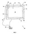
- FIG. 2is a schematic representation of one embodiment of an apparatus for detecting a pointer within a region of interest in accordance with the present invention
- FIG. 3is a schematic representation of an imaging device forming part of the apparatus of FIG. 2 ;
- FIG. 4is a cross-sectional view of a portion of a touch panel forming part of the apparatus of FIG. 2 ;
- FIG. 5is a cross-sectional view of another portion of the touch panel
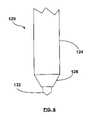
- FIG. 6is a side elevation view of an active pointer for use with the apparatus of FIG. 2 ;
- FIG. 7is a schematic representation of a touch panel assembly showing the lines of sight of the imaging device that intersect a passive pointer
- FIG. 8shows an image captured by the imaging device with the passive pointer in contact with the touch panel
- FIG. 9shows actual and virtual touch panel assemblies
- FIG. 10is a schematic representation of the touch panel assembly showing the lines of sight of the imaging device that intersect an active pointer
- FIG. 11shows an image captured by the imaging device with the active pointer in contact with the touch panel
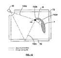
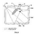
- FIGS. 12 and 13are schematic representations of the touch panel assembly showing different writing scenarios
- FIGS. 14 to 16show alternative embodiments of touch panel assemblies
- FIG. 17is a perspective view of yet another embodiment of a touch panel assembly
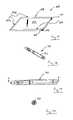
- FIG. 18is a perspective view of an active pen for use with the touch panel assembly of FIG. 17 ;
- FIGS. 19 and 20are side and end views of the pen of FIG. 18 ;
- FIG. 21is a sectional view of the pen taken along line A-A in FIG. 19 ;
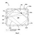
- FIG. 22is a top plan view of the touch panel assembly of FIG. 17 .
- apparatus 20is in the form of a touch system.
- the touch system 20includes a generally rectangular touch panel assembly 24 encompassing the region of interest.
- Touch panel assembly 24includes a generally transparent touch panel 28 that overlies the display screen of a display unit such as for example, a flat-panel monitor or the like (not shown) and an imaging device 48 that is positioned adjacent one corner of the touch panel 28 .
- the imaging device 48looks both across and through the touch panel 28 and acquires images within its field of view.
- the acquired imagesare processed by the imaging device 48 to determine whether a pointer exists in the captured images and if so, to determine the location of the pointer relative to the touch panel 28 .
- Pointer location data generated by the imaging device 48is conveyed to a computer 32 executing one or more application programs.
- the computer 32uses the pointer location data generated by the touch panel assembly 24 to update computer-generated images that are presented on the display screen. Pointer contacts on the touch panel 28 can therefore be recorded as writing or drawing or used to control execution of application programs executed by the computer 32 .
- Touch panel 28 in this embodimentis a waveguide constructed of transparent plastic so that the display screen is visible through it.
- the upper surface of the waveguide 28defines a touch surface 40 on which pointer contacts are to be made.
- a protective film or coatingcan be applied to the touch surface 40 to protect the waveguide from scratching and/or marking.
- a smoothly curved cutout 64is provided in the waveguide 28 at the corner thereof adjacent the imaging device 48 .
- the curved surface of the cutout 64is diamond polished.
- the imaging device 48is positioned generally at the center of the circle described by the curved cutout 64 .
- the radius of the curved cutout 64is equal to the distance between the pupil of the imaging device 48 and the curved surface of the cutout, light exiting the waveguide 28 through the curved surface of the cutout 64 towards the imaging device 48 does not undergo refraction as a result of the plastic to air transition, thereby reducing distortion.
- Imaging device 48is best illustrated in FIG. 3 and includes a high resolution 1280 ⁇ 1024 CMOS digital camera 52 such as that manufactured by National Semiconductors under model No. LM9638 and an associated lens 56 .
- a digital signal processor (DSP) 60is coupled to the digital camera 52 .
- the digital camera 52 and DSP 60are mounted on a common circuit board. The circuit board is positioned with respect to the waveguide 28 so that the digital camera 52 looks out across the plane of the touch surface 40 and into the waveguide 28 .
- the lens 56has a 90-degree field of view so that the entire region of interest is within the field of view of the digital camera 52 .
- the DSP 60is coupled to the computer 32 via a universal serial bus (USB) or RS232 serial cable 68 .
- the digital camera 52 in this embodimentis configured to have an active 80 ⁇ 1280 pixel sub-array allowing it to be operated to capture image frames at high frame rates (i.e. in excess of 200 frames per second).
- the waveguide 28is bordered by a triangular turning prism assembly 72 , a mirror 92 and a pair of illuminated bezels 112 and 116 .
- the turning prism assembly 72extends along one of the sides of the waveguide 28 that is opposite the imaging device 48 .
- FIG. 4best illustrates the turning prism assembly 72 .
- the turning prism assembly 72includes a transparent plastic spill guard 74 extending along and abutting the side of the waveguide 28 .
- the spill guard 74projects above the touch surface 40 by a height equal to about 4 mm.
- a turning prism 76commonly referred to as a Porro prism, is positioned behind and slightly spaced from the spill guard 74 .
- the turning prism 76is similar in height to the spill guard 74 and includes a pair of reflecting surfaces 78 and 80 that intersect at a right angle. The line of intersection of the reflecting surfaces 78 and 80 is in the same plane as the touch surface 40 .
- turning prism 76is a length of plastic or glass that has an index of refraction similar to that of the waveguide 28 to reduce optical losses.
- the surface of the spill guard 74 facing the turning prism 76includes an anti-reflection coating 82 further to inhibit optical losses.
- Light entering turning prism 76 at an angle of less than 45 degreesis internally reflected off of the reflecting surfaces 78 and 80 and redirected out of the turning prism 76 along a path parallel to the path of entry. Any directional component of light in the third dimension normal to the cross-sectional view of FIG. 4 is preserved in the light as such light is reflected by face 84 of the turning prism 76 .
- light 88 a travelling above and parallel to the plane of the touch surface 40upon encountering the turning prism assembly 72 , passes through the spill guard 74 , enters the turning prism 76 , is reflected internally off of the reflecting surfaces 78 and 80 before being redirected out of the turning prism, passes back through the spill guard 74 and enters the waveguide 28 .
- light 88 b travelling within the waveguide 28 parallel the plane of the touch surface 40 upon encountering the turning prism assembly 72passes through the spill guard 74 , enters the turning prism 76 , reflects internally off of the reflecting surfaces 80 and 78 before being redirected out of the turning prism, passes back through the spill guard 74 and travels over the touch surface 40 .
- the mirror 92extends along and abuts the other side of the waveguide 28 that is opposite the imaging device 48 .
- the turning prism assembly 72 and mirror 92meet at the corner of the waveguide 28 that is diagonally opposite to the imaging device 48 .
- the mirror 92also projects above the touch surface 40 by a height similar to that of the turning prism assembly 72 .
- Mirror 92is a length of glass having an internal planar reflective surface 100 that is oriented so that its plane is generally perpendicular to the plane of the touch surface 40 .
- light 104 a travelling above and parallel to the plane of the touch surface 40upon encountering the mirror 92 , is reflected by the reflective surface 100 back above the touch surface 40 along a path in the same plane.
- light 104 b travelling within the waveguide 28 parallel to the plane of the touch surface 40upon encountering the mirror 92 is reflected back through the waveguide 28 along a path in the same plane.
- the infrared illuminated bezels 112 and 116extend along and abut the remaining two sides of the waveguide 28 .
- the infrared illuminated bezels 112 , 116also project above the touch surface 40 by a height similar to that of the turning prism assembly 72 and mirror 92 .
- the infrared illuminated bezels 112 and 116project infrared light across the touch surface 40 and through the waveguide 28 towards the reflecting surfaces 78 and 80 of the turning prism 76 and towards the reflective surface 100 of the mirror 92 thereby to provide appropriate bands of infrared backlighting for the imaging device 48 .
- the touch system 20when the touch system 20 is operating in a passive mode with the illuminated bezels 112 and 116 in an on condition, and a pointer is located within the region of interest, the pointer occludes light and appears to the imaging device 48 as dark objects against a white background.
- the infrared illuminated bezels 112 and 116are of the type described in U.S. patent application Ser. No. 10/354,168 entitled “Illuminated Bezel And Touch System Incorporating The Same” to Akitt et al. filed on Jan. 30, 2003 and assigned to SMART Technologies Inc., assignee of the present invention, the content of which is incorporated herein by reference. Accordingly, specifics of the infrared illuminated bezels 112 and 116 will not be described further herein.
- a radio frequency receiver 119is also accommodated by the touch panel assembly 24 and communicates with the illuminated bezels 112 and 116 .
- the radio frequency receiver 119turns the illuminated bezels off upon receipt of radio signals signifying operation of the touch system 20 in an active mode. When no radio signals are received by the radio frequency receiver 119 , the illuminated bezels 112 and 116 remain on signifying operation of the touch system 20 in the passive mode.
- FIG. 6shows an active pointer 120 for use with the touch system 20 when the touch system is to be operated in the active mode.
- the pointer 120has a main body 124 terminating in a frustoconical tip 128 .
- the tip 128houses a number of miniature infrared LEDs (not shown). The infrared LEDs are powered by a battery (not shown), also housed in the main body 124 .
- Protruding from the tip 128is an actuator 132 .
- Actuator 132is biased out of the tip 128 by a spring (not shown) but can be pushed into the tip 128 upon application of pressure thereto.
- the actuator 132is connected to a switch (not shown) within the main body 124 that closes a circuit to power the infrared LEDs when the actuator 132 is pushed against the spring bias into the tip 128 . With the LEDs powered, the pointer 120 emits a wide spread beam of infrared light from its tip 128 .
- a radio frequency transmitter(not shown) within the main body 124 is powered causing the transmitter to emit radio signals. The radio signals are received by the receiver 119 causing the receiver 119 to switch the illuminated bezels 112 and 116 off thereby to condition the touch system 20 to the active mode.
- the actuator 132is biased out of the tip 128 , the circuit remains open and, resultingly, neither infrared light nor radio signals are emitted by the pointer 120 .
- the operation of the touch system 20 in the passive modewill firstly be described.
- the illuminated bezels 112 and 116are conditioned to project infrared backlighting over the touch surface 40 and through the waveguide 28 .
- the imaging device 48sees bright bands of illumination within its field of view.
- the pointer PWhen a pointer P is brought into contact with the touch surface 40 and therefore, into the field of view of the imaging device 48 , the pointer occludes backlight illumination and therefore appears as dark regions interrupting the bright bands of illumination seen by the imaging device 48 .
- Paths 144 a to 144 drepresent the lines of sight of the imaging device 48 that intersect the pointer P and hence, correspond with the dark regions i.e. those lines of sight where the backlight illumination has been interrupted or occluded by the pointer P.
- Path 144 ais the line of sight of the imaging device 48 aimed directly at the pointer P over the touch surface 40 .
- Pointer Pin this case occludes light emitted by the illuminated bezel 116 that travels through the waveguide 28 , is redirected by the turning prism assembly 72 and travels over the touch surface 40 .
- Path 144 bis the line of sight of the imaging device 48 looking through the waveguide 28 that sees the left reflection of the pointer P in the turning prism assembly 72 .
- Pointer P in this caseoccludes light emitted by the illuminated bezel 116 that travels over the touch surface 40 directly at the pointer P.
- Path 144 cis the line of sight of the imaging device 48 looking across the touch surface 40 that sees the right reflection of the pointer P in the mirror 92 .
- Pointer Pin this case occludes light emitted by the illuminated bezel 112 that travels over the touch surface 40 directly at the pointer P.
- Path 144 dis the line of sight of the imaging device 48 looking through the waveguide 28 that sees the double reflection of the pointer P in the mirror 92 .
- Pointer P in this caseoccludes light emitted by the illuminated bezel 112 that travels over the touch surface 40 directly at the pointer P.
- the pointer Poccludes infrared backlighting along two lines of sight of imaging device 48 extending across the touch surface 40 and along two lines of sight of the imaging device 48 extending through the waveguide 28 .
- two dark regions 148 a , 148 c and 148 b , 148 d representing the pointer Pappear in each bright band of illumination seen by the imaging device 48 as shown in FIG. 8 allowing the location of the pointer P to be calculated using triangulation.
- the use of the mirror 92 and turning prism assembly 72effectively creates a touch system 20 equivalent to a touch system that is four times as large with virtual imaging devices 48 ′ at each of its corners as shown in FIG. 9 .
- the pointer reflectionscan be considered to be seen by the virtual imaging devices 48 ′ with the pointer reflections determining the positions of the virtual angles.
- Anglesare associated with the virtual images and these angles are identical to the angles ⁇ 0 to ⁇ 3 associated with the pointer and pointer reflections illustrated in FIG. 7 .
- the imageis processed by the DSP 60 in a manner similar to that described in U.S. patent application Ser. No. 10/681,330 filed on Oct. 9, 2003 to Ung et al, assigned to SMART Technologies Inc., assignee of the present invention, the content of which is incorporated herein by reference, to determine the location of pointer contact on the touch surface 40 .
- the pointer location datais then conveyed to the computer 32 .
- the touch system 20is calibrated to take refraction caused by the air to plastic and plastic to air transitions into account so that the pointer location data processed by the computer 32 accurately reflects the actual point of contact on the touch surface 40 of the waveguide 28 .
- the receiver 119turns the illuminated bezels 112 and 116 off in response to radio signals emitted by the pointer 120 when the pointer is brought into contact with the touch surface 40 with sufficient force to push the actuator 132 into the tip 128 .
- the LEDs in the tip 128are powered causing the pointer 120 to emit a wide spread beam of infrared light from its tip.
- the imaging device 48receives emitted light travelling over the touch surface 40 directly from the pointer 120 as identified by path 152 a .
- the imaging device 48also receives emitted light travelling over the touch surface 40 that reflects off of the mirror 92 as identified by path 152 c .
- the imaging device 48also receives emitted light that travels over the touch surface 40 , is redirected by the turning prism assembly 72 and travels through the waveguide 28 as identified by path 152 b .
- the imaging device 48further receives emitted light that travels over the touch surface 40 , is redirected by the turning prism assembly 72 into the waveguide 28 , is reflected off of the mirror 92 before continuing through the waveguide 28 as identified by path 152 d .
- the pointer 120appears as light regions 156 a to 156 d interrupting dark bands. Similar to the passive mode, two light regions representing the pointer 120 appear in each dark band allowing the location of pointer contact on the touch surface 40 to be calculated using triangulation.
- the imaging device 48sees the pointer looking both across the touch surface 40 and through the waveguide 28 , the imaging device 48 is able to see pointer contacts with the touch surface 40 even in situations where the user rests his forearm and/or hand on the touch surface 40 during writing at locations where the forearm and/or hand block the imaging device's direct line of sight to the pointer.
- FIG. 12illustrates a writing scenario where a right-handed user rests his forearm F and hand H on the touch surface 40 while writing with the pointer 120 .
- the pointer 120is shown in the same position as in FIG. 10 , thus creating the same light paths 152 a , 152 b , 152 c and 152 d .
- the user's forearm F and hand Hobstruct the light emitted by the pointer 120 travelling along paths 152 b and 152 d .
- the emitted light travelling along paths 152 a and 152 chowever remains unobstructed allowing the true pointer and right pointer reflection to be captured in an image.
- the location of pointer contact on the touch surface 40can still be calculated using triangulation.
- FIG. 13illustrates a writing scenario where a left-handed user rests his forearm F and hand H on the touch surface 40 while writing with the pointer 120 .
- the pointer 120is, again, shown in the same position as in FIG. 10 , thus creating the same light paths 152 a , 152 b , 152 c and 152 d .
- the usercurls his left forearm F and hand H in an exaggerated manner, sometimes referred to as a “left hook”.
- the user's forearm F and hand Hobstruct the light emitted by the pointer 120 travelling only along path 152 a .
- the emitted light travelling along paths 152 b and 152 dreaches the imaging device 48 through the waveguide 28 and thus, passes beneath the user's forearm F and hand H.
- the right, left and double pointer reflectionscan be captured in an image allowing the location of pointer contact on the touch surface 40 to be calculated using triangulation.
- the touch system 20allows the locations of pointer contacts on the touch surface 40 to be determined even though the user's style of writing may block the imaging device's direct line of sight to the pointer. This yields a high-resolution touch system.
- FIG. 14shows an alternative embodiment of a touch panel assembly 224 .
- touch panel assembly 224includes a generally rectangular waveguide 228 having an upper touch surface 240 .
- a smoothly curved cutout 264is provided generally centrally along one side of the waveguide 228 .
- An imaging device 248is positioned adjacent the cutout and looks both across the touch surface 240 and into the waveguide 228 .
- Illuminated bezels 212 and 216extend along and abut the side of the waveguide flanking the cutout 264 .
- the illuminated bezels 212 and 216also extend above the touch surface 240 .
- Infrared light sources(not shown) are also strung above and below the imaging device 248 .
- the illuminated bezels 212 and 216 and infrared light sourcesprovide infrared backlighting both across the touch surface 240 and through the waveguide 228 .
- a turning prism assembly 272 similar to that of the previous embodimentextends along the side of the waveguide 228 opposite the imaging device 248 .
- Mirrors 292 a and 292 bextend along and abut the remaining two sides of the waveguide 228 .
- the mirrors 292 a and 292 bsimilarly project above the touch surface 240 .
- Waveguide 228 , illuminated bezels 212 and 216 , infrared light sources, imaging device 248 , turning prism assembly 272 and mirrors 292 a and 292 bfunction in a similar manner to waveguide 40 , imaging device 48 , turning prism 72 , mirror 92 , and illuminated bezels 112 and 116 of the first embodiment.
- the touch panel assembly 224can operate in a passive or active mode. In the passive mode, the illuminated bezels 212 and 216 and infrared light sources are illuminated and project infrared backlighting across the touch surface 240 and through the waveguide 228 .
- the imaging device 248therefore sees bright bands of illumination when no pointer is within its field of view.
- the pointer PWhen a pointer P is brought into the field of view of the imaging device 248 and contacts the touch surface 240 , the pointer P occludes backlighting.
- the pointer P and reflections of the pointer in the turning prism assembly 272 and mirrors 292 a and 292 bappear as dark regions against a white background in captured images allowing the locations of pointer contacts on the touch surface 240 to be calculated using triangulation.
- the pointer Poccludes backlighting along four lines of sight 232 a to 232 d of the imaging device 248 resulting in four dark regions appearing in a captured image.
- Path 232 ais the line of sight of the imaging device 248 looking through the waveguide 228 that sees the reflection of the pointer P in the turning prism assembly 272 .
- Pointer Pin this case occludes light emitted by illuminated bezel 212 that travels over the touch surface 240 directly at the pointer.
- Path 232 bis the line of sight of the imaging device 248 looking across the touch surface 240 directly at the pointer P.
- Pointer P in this caseoccludes light emitted by the illuminated bezel 212 that travels through the waveguide 228 to mirror 292 a , reflects off of mirror 292 a and continues through the waveguide 228 to the turning prism assembly 272 , and is redirected by the turning prism assembly 272 over the touch surface 240 towards the pointer P.
- Path 232 cis the line of sight of the imaging device 248 looking through the waveguide 228 that sees the double reflection of the pointer in the mirror 292 b .
- Pointer P in this caseoccludes light emitted by the illuminated bezel 212 that travels over the touch surface 240 and is reflected by mirror 292 a at the pointer P.
- Path 232 dis the line of sight of the imaging device 248 looking across the touch surface 240 that sees the reflection of the pointer P in the mirror 292 a .
- Pointer Pin this case occludes light emitted by the illuminated bezel 212 that travels through the waveguide 228 to mirror 292 b , reflects off of mirror 292 b and continues through the waveguide 228 to the turning prism assembly 272 and is redirected by the turning prism assembly 272 over the touch surface 240 toward the pointer P.
- the illuminated bezels 212 and 216 and infrared light sourcesare turned off and the active pointer 120 , which emits light upon contact with the touch surface 240 , is used.
- Light emitted by the pointer 120may travel directly to the imaging device 248 and/or reflect off of the turning prism assembly 272 and mirrors 292 a and 292 b before travelling to the imaging device either across the touch surface 240 or through the waveguide 228 .
- the pointer 120 and its reflectionsappear as bright regions against a dark background in captured images allowing the locations of pointer contacts on the touch surface 240 to be calculated using triangulation.
- the touch panel assembly 224is advantageous in that reduced lengths of infrared illuminated bezels are required, thus decreasing manufacturing costs.
- FIG. 15shows yet another embodiment of a touch panel assembly 324 .
- touch panel assembly 324includes a generally rectangular waveguide 328 having an upper touch surface 340 .
- a smoothly curved cutout 364is provided at one corner of the waveguide 328 .
- An imaging device 348is positioned adjacent the cutout and looks across the touch surface 340 and through the waveguide 328 .
- Illuminated bezels 312 and 316 arranged at right anglesextend along two sides of the waveguide 328 .
- the illuminated bezels 312 and 316extend above the touch surface 340 and thus, project infrared backlighting both across the touch surface 340 and through the waveguide.
- a turning prism assembly 372extends along the side of the waveguide 328 that intersects the illuminated bezel 316 at a corner diagonally opposite the imaging device 348 .
- the illuminated bezels 312 and 316are illuminated and project infrared backlighting both across the touch surface 340 and through the waveguide 328 .
- the imaging device 348therefore sees bright bands of illumination when no pointer is within its field of view.
- a pointer Pis brought into the field of view of the imaging device 348 and contacts the touch surface 340 , the pointer P occludes backlighting.
- the pointer P and reflections of the pointer in the turning prism assembly 372appear as dark regions against a white background in captured images allowing the locations of pointer contacts on the touch surface 340 to be calculated using triangulation.
- the pointer Poccludes backlighting along two lines of sight 344 a and 344 b resulting in two dark regions appearing in a captured image.
- Path 344 ais the line of sight of the imaging device 348 looking across the touch surface 340 directly at the pointer P.
- Path 344 bis the line of sight of the imaging device 348 looking through the waveguide 328 that sees the reflection of the pointer P in the turning prism assembly 372 .
- the illuminated bezels 312 and 316are turned off and the active pointer 120 , which emits light upon contact with the touch surface 340 , is used.
- Light emitted by the pointer 120may travel directly to the imaging device 348 across the touch surface 340 or reflect off of the turning prism assembly 372 before travelling to the imaging device 348 through the waveguide 328 .
- the pointer 120 and its reflection in the turning prism assembly 372appear as bright regions against a dark background in captured images allowing the locations of pointer contacts on the touch surface 340 to be calculated using triangulation.
- uniform illuminated bezelsthat always remain on and project light having an intensity that does not saturate the imaging device(s) can be used.
- an active pointerthat projects light having an intensity greater than that of the light projected by the illuminated bezels is used so that the pen and its reflections can be discerned from the background light in captured images.
- the illuminated bezels and the active pointercan be pulsed at different frequencies allowing the touch systems to operate in dual modes.
- FIG. 16shows still yet another embodiment of a touch panel assembly 424 .
- the touch panel assembly 424includes a generally rectangular touch panel 428 with two mirrors 492 a and 492 b extending along its opposite sides. Cutouts 464 a and 464 b are centrally provided in opposite sides of the touch panel 428 and accommodate imaging devices 448 a and 448 b . Illuminated bezels 412 and 416 extend along the sides of the touch panel 428 flanking the cutouts 464 a and 464 b . Infrared light sources (not shown) are also strung above and below the imaging devices 448 a and 448 b.
- touch panel assembly 624includes a touch panel or tablet 628 that is generally rectangular in top plan.
- the tablet 628overlies a display screen or monitor such as for example a liquid crystal display and is generally transparent to visible light so that images presented on the display screen can be seen through the tablet.
- a smoothly curved cutout 664is provided in the tablet at one corner.
- An imaging device 648is accommodated by the cutout 664 and has a field of view looking into the tablet 628 .
- the tablet 628 in this embodimentis formed of acrylic material such as that manufactured by GE Plastics under type No. GP FL.
- the acrylic materialis doped with a pigment that fluoresces in response to light in the ultraviolet (UV) range.
- the side surfaces 631 and 633 of the tablet 628 that extend from and flank the cutout 664are diffused surfaces.
- the side surfaces 692 a and 692 b of the tablet 628 that intersect at a corner diagonally opposite the imaging device 648are highly polished and reflective thereby to define total internal reflection (TIR) mirrors.
- the tablet 628acts as a waveguide so that light travelling therein is totally internally reflected.
- An anti-reflective coating and a filter coatingare provided on the upper surface 640 of the tablet 628 .
- the filter coatingacts as a UV bandpass filter to reduce ambient light from entering into the tablet.
- a protective transparent layermay be provided over the upper surface 640 to inhibit the tablet 628 from being damaged or scratched.
- the beam of UV lightcauses a region within the tablet interior to fluoresce and hence, glow blue in color.
- the imaging device 648which looks into the interior of the tablet sees the glowing region directly as well as one or more reflections of the glowing region appearing in the reflective surfaces 692 a and 692 b . As a result, images captured by the imaging device 648 can be processed to detect the location of the glowing region and hence, the location of the UV light source relative to the surface 640 using triangulation.
- the source of UV lightis in the form of a pen 700 having a casing 702 accommodating a UV light emitting diode (LED) 704 , a lens system and waveguide 706 , a pulsing circuit 708 and a power source 710 , in this case a battery.
- the casing 702can be opened to permit access to the battery 710 to allow the battery to be replaced but is completely sealed to inhibit access to the UV LED 704 , lens system and waveguide 706 and the pulsing circuit 708 .
- the waveguideis in the form of a light pipe having converging sides and a roughned narrow tip.
- a tip switch 712is provided at the distal end of the casing 702 that is activated when the tip of the pen 700 is brought into contact with the upper surface 640 . When activated, the tip switch 712 actuates a microswitch 714 causing the pen 700 to illuminate.
- the pulsing circuit 708is powered resulting in the UV LED 704 being energized in a manner to cause the UV LED to generate pulses of UV light at a 10% duty cycle.
- the pulses of UV light generated by the UV LED 704are directed to the lens system and waveguide 706 .
- the lens system and waveguide 706in turn directs the UV light pulses to the tip of pen, focuses the UV light pulses to a pinpoint at the tip prior to dispersing the UV light pulses from the tip of the pen 700 at a large angle.
- FIG. 22shows the pen 700 being used to write on the upper surface 640 of the tablet 628 . Movement of the pen 700 over the tablet 628 is tracked and mapped to the coordinate system of the display so that the pen movement is used to update the images presented by the display.
- the imaging device 648looks into the interior of the tablet 628 and not over and across the surface of the tablet, contact between portions of the user's body such as the hand and/or forearm during writing does not impede the ability of the touch panel assembly 624 to track movement of the pen across the tablet.
- a non-reflective regioncan be provided at the corner of the tablet that is diagonally opposite the imaging device 648 to avoid the imaging device from seeing an image of the glowing region resulting from a double reflection when the pen is brought into close proximity with the corner as described in co-pending U.S. patent application Ser. No. 10/681,330 to Ung et al., assigned to SMART Technologies Inc., assignee of the present invention.
- the non-reflective regioncan be in the plane of one or both of the reflective surfaces 692 a and 692 b.
- each mirrorcan be replaced with a turning prism assembly.
- the imaging devicecan be configured only to look into the waveguide. In this manner, images including pointer reflection that are directed into the waveguide are processed to determine pointer contacts on the touch surface.
- mirrorsmay need to be replaced with turning prism assemblies.
- the mirrorsare described as having generally planar reflective surfaces, other mirror configurations can be used.
- the mirrorscan be made to have a convex vertical profile.
- the reflective surfacesmay also include v-grooves with the v-grooves extending along the length of the mirror.
- Other suitable mirror configurationswill also be apparent to those skilled in the art.
- the sides of the waveguidecan be polished thereby to form TIR mirrors. In this case, only mirrors extending above the touch surface of the waveguide are required.
- air spaced mirrorsmay also be used.
- the radius of the curved cutoutcan be altered to expand or reduce the field of view of the imaging device although this may create slight distortion as a result of refraction due to the plastic to air transition.
- the active pointercan be designed to emit other types of signals that can be detected to enable the touch system to be conditioned to the active mode.
- the touch panel assembliesmay include a receptacle for the active pointer.
- a sensor associated with the receptaclewhen the active pointer is removed from the receptacle, a sensor associated with the receptacle generates output that is used to signify operation of the touch system in the active mode and hence, turn off the illuminated bezels.
- the touch systemreverts back to the passive mode and hence, the illuminated bezels are turned on.
- a unique feature or characteristic associated with the active pointerthat can be discerned from images captured by the imaging device can be used to condition the touch system to the active mode.
- the active pointermay be designed to have a unique profile or to carry an identifying glyph.
- the waveguidemay be placed a distance behind the touch surface, such as behind a monitor over which the touch surface is disposed.
- the turning prism assemblymakes use of prisms that are capable of redirecting light over these distances, such as for example inverted dove prisms.
- touch panel assembliesare described as overlying a display screen on which an image is presented, those of skill in the art will appreciate that the touch panel assemblies may be used in a whiteboard environment where a projector is used to project an image on the touch surface.
Landscapes
- Engineering & Computer Science (AREA)
- General Engineering & Computer Science (AREA)
- Theoretical Computer Science (AREA)
- Human Computer Interaction (AREA)
- Physics & Mathematics (AREA)
- General Physics & Mathematics (AREA)
- Position Input By Displaying (AREA)
Abstract
Description
Claims (34)
Priority Applications (3)
| Application Number | Priority Date | Filing Date | Title |
|---|---|---|---|
| US10/834,190US7460110B2 (en) | 2004-04-29 | 2004-04-29 | Dual mode touch system |
| US12/262,221US8274496B2 (en) | 2004-04-29 | 2008-10-31 | Dual mode touch systems |
| US13/626,790US20130120316A1 (en) | 2004-04-29 | 2012-09-25 | Dual mode touch systems |
Applications Claiming Priority (1)
| Application Number | Priority Date | Filing Date | Title |
|---|---|---|---|
| US10/834,190US7460110B2 (en) | 2004-04-29 | 2004-04-29 | Dual mode touch system |
Related Child Applications (1)
| Application Number | Title | Priority Date | Filing Date |
|---|---|---|---|
| US12/262,221DivisionUS8274496B2 (en) | 2004-04-29 | 2008-10-31 | Dual mode touch systems |
Publications (2)
| Publication Number | Publication Date |
|---|---|
| US20050243070A1 US20050243070A1 (en) | 2005-11-03 |
| US7460110B2true US7460110B2 (en) | 2008-12-02 |
Family
ID=35186587
Family Applications (3)
| Application Number | Title | Priority Date | Filing Date |
|---|---|---|---|
| US10/834,190Expired - Fee RelatedUS7460110B2 (en) | 2004-04-29 | 2004-04-29 | Dual mode touch system |
| US12/262,221Expired - Fee RelatedUS8274496B2 (en) | 2004-04-29 | 2008-10-31 | Dual mode touch systems |
| US13/626,790AbandonedUS20130120316A1 (en) | 2004-04-29 | 2012-09-25 | Dual mode touch systems |
Family Applications After (2)
| Application Number | Title | Priority Date | Filing Date |
|---|---|---|---|
| US12/262,221Expired - Fee RelatedUS8274496B2 (en) | 2004-04-29 | 2008-10-31 | Dual mode touch systems |
| US13/626,790AbandonedUS20130120316A1 (en) | 2004-04-29 | 2012-09-25 | Dual mode touch systems |
Country Status (1)
| Country | Link |
|---|---|
| US (3) | US7460110B2 (en) |
Cited By (47)
| Publication number | Priority date | Publication date | Assignee | Title |
|---|---|---|---|---|
| US20080029691A1 (en)* | 2006-08-03 | 2008-02-07 | Han Jefferson Y | Multi-touch sensing display through frustrated total internal reflection |
| US20080084539A1 (en)* | 2006-10-06 | 2008-04-10 | Daniel Tyler J | Human-machine interface device and method |
| US20080125223A1 (en)* | 2006-11-29 | 2008-05-29 | Nintendo Co., Ltd. | Information processing apparatus and storage medium storing information processing program |
| US20090103853A1 (en)* | 2007-10-22 | 2009-04-23 | Tyler Jon Daniel | Interactive Surface Optical System |
| US20090146973A1 (en)* | 2004-04-29 | 2009-06-11 | Smart Technologies Ulc | Dual mode touch systems |
| US20100201637A1 (en)* | 2009-02-11 | 2010-08-12 | Interacta, Inc. | Touch screen display system |
| US20100207910A1 (en)* | 2009-02-19 | 2010-08-19 | Quanta Computer, Inc. | Optical Sensing Screen and Panel Sensing Method |
| CN101847063A (en)* | 2010-03-03 | 2010-09-29 | 苏州佳世达电通有限公司 | System and method for detecting object by using non-coincident fields of light |
| CN101856933A (en)* | 2009-04-13 | 2010-10-13 | 鸿富锦精密工业(深圳)有限公司 | Information recording device and optical handwriting system |
| US20100271333A1 (en)* | 2009-04-25 | 2010-10-28 | Hon Hai Precision Industry Co., Ltd. | Optical touch screen device |
| US20100271334A1 (en)* | 2009-04-27 | 2010-10-28 | Hon Hai Precision Industry Co., Ltd. | Touch display system with optical touch detector |
| US20100309169A1 (en)* | 2009-06-03 | 2010-12-09 | Lumio Inc. | Optical Touch Screen with Reflectors |
| CN101923418A (en)* | 2010-03-07 | 2010-12-22 | 苏州佳世达电通有限公司 | Object sensing system and method |
| CN101957689A (en)* | 2009-07-14 | 2011-01-26 | 原相科技股份有限公司 | Sensing system and method for obtaining position of referent thereof |
| US20110018805A1 (en)* | 2009-07-21 | 2011-01-27 | Qisda Corporation | Location-detecting system and arrangement method thereof |
| US20110025620A1 (en)* | 2008-01-11 | 2011-02-03 | Opdi Technologies A/S | Touch-sensitive device |
| EP2284668A2 (en) | 2009-06-15 | 2011-02-16 | SMART Technologies ULC | Interactive input system and components therefor |
| US20110043484A1 (en)* | 2009-08-21 | 2011-02-24 | Largan Precision Co., Ltd. | Apparatus for detecting a touching position on a flat panel display and a method thereof |
| US20110050649A1 (en)* | 2009-09-01 | 2011-03-03 | John David Newton | Determining the Location of Touch Points in a Position Detection System |
| US20110069037A1 (en)* | 2009-09-24 | 2011-03-24 | Dong-Hsing Su | Optical touch system and method |
| US20110074738A1 (en)* | 2008-06-18 | 2011-03-31 | Beijing Irtouch Systems Co., Ltd. | Touch Detection Sensing Apparatus |
| CN102043539A (en)* | 2009-10-09 | 2011-05-04 | 大立光电股份有限公司 | Device for detecting position of panel display and method thereof |
| US20110102373A1 (en)* | 2009-11-04 | 2011-05-05 | Hon Hai Precision Industry Co., Ltd. | Optical pen and optical touch device having same |
| US20110115904A1 (en)* | 2009-11-18 | 2011-05-19 | Qisda Corporation | Object-detecting system |
| US20110157044A1 (en)* | 2009-12-26 | 2011-06-30 | Byung Chun Yu | Optical touch input system and method of establishing reference in the same |
| US20110157091A1 (en)* | 2009-12-29 | 2011-06-30 | Hon Hai Precision Industry Co., Ltd. | Touch-enabled display device |
| US20110157101A1 (en)* | 2009-12-28 | 2011-06-30 | Hon Hai Precision Industry Co., Ltd. | Electronic whiteboard system |
| US20110169782A1 (en)* | 2002-12-10 | 2011-07-14 | Neonode, Inc. | Optical touch screen using a mirror image for determining three-dimensional position information |
| US20110241984A1 (en)* | 2010-03-31 | 2011-10-06 | Smart Technologies Ulc | Illumination structure for an interactive input system |
| USD652427S1 (en)* | 2009-06-03 | 2012-01-17 | Smart Technologies Ulc | Display screen with a user interface |
| US8115753B2 (en) | 2007-04-11 | 2012-02-14 | Next Holdings Limited | Touch screen system with hover and click input methods |
| US8149221B2 (en) | 2004-05-07 | 2012-04-03 | Next Holdings Limited | Touch panel display system with illumination and detection provided from a single edge |
| US8188968B2 (en)* | 2002-07-27 | 2012-05-29 | Sony Computer Entertainment Inc. | Methods for interfacing with a program using a light input device |
| CN102511024A (en)* | 2009-08-25 | 2012-06-20 | 夏普株式会社 | Location identification sensor, electronic device, and display device |
| US8289299B2 (en) | 2003-02-14 | 2012-10-16 | Next Holdings Limited | Touch screen signal processing |
| CN101840281B (en)* | 2009-03-20 | 2012-12-05 | 原相科技股份有限公司 | Sensing system and method thereof for obtaining position of pointer |
| US8384693B2 (en) | 2007-08-30 | 2013-02-26 | Next Holdings Limited | Low profile touch panel systems |
| US8405636B2 (en) | 2008-01-07 | 2013-03-26 | Next Holdings Limited | Optical position sensing system and optical position sensor assembly |
| US8432377B2 (en) | 2007-08-30 | 2013-04-30 | Next Holdings Limited | Optical touchscreen with improved illumination |
| US20130135254A1 (en)* | 2011-11-30 | 2013-05-30 | Research In Motion Limited | Optical interference based user input device |
| US8456447B2 (en) | 2003-02-14 | 2013-06-04 | Next Holdings Limited | Touch screen signal processing |
| US8508508B2 (en) | 2003-02-14 | 2013-08-13 | Next Holdings Limited | Touch screen signal processing with single-point calibration |
| TWI423095B (en)* | 2010-02-09 | 2014-01-11 | Qisda Corp | Object-detecting system and method by use of non-coincident fields of light |
| US8797260B2 (en) | 2002-07-27 | 2014-08-05 | Sony Computer Entertainment Inc. | Inertially trackable hand-held controller |
| US8892790B2 (en) | 2010-03-12 | 2014-11-18 | Beijing Irtouch Systems Co., Ltd | Control panel and serial port communication arbiter for touch screen with camera |
| US20160253043A1 (en)* | 2013-10-08 | 2016-09-01 | Hitachi Maxell, Ltd. | Projection type image display device, manipulation detection device and projection type image display method |
| USD1009883S1 (en)* | 2019-11-19 | 2024-01-02 | Johnson Systems Inc. | Display screen with graphical user interface |
Families Citing this family (88)
| Publication number | Priority date | Publication date | Assignee | Title |
|---|---|---|---|---|
| US6803906B1 (en) | 2000-07-05 | 2004-10-12 | Smart Technologies, Inc. | Passive touch system and method of detecting user input |
| US6954197B2 (en) | 2002-11-15 | 2005-10-11 | Smart Technologies Inc. | Size/scale and orientation determination of a pointer in a camera-based touch system |
| US7532206B2 (en) | 2003-03-11 | 2009-05-12 | Smart Technologies Ulc | System and method for differentiating between pointers used to contact touch surface |
| US7411575B2 (en) | 2003-09-16 | 2008-08-12 | Smart Technologies Ulc | Gesture recognition method and touch system incorporating the same |
| US7274356B2 (en) | 2003-10-09 | 2007-09-25 | Smart Technologies Inc. | Apparatus for determining the location of a pointer within a region of interest |
| US7355593B2 (en) | 2004-01-02 | 2008-04-08 | Smart Technologies, Inc. | Pointer tracking across multiple overlapping coordinate input sub-regions defining a generally contiguous input region |
| US8120596B2 (en) | 2004-05-21 | 2012-02-21 | Smart Technologies Ulc | Tiled touch system |
| US20090090569A1 (en)* | 2005-10-13 | 2009-04-09 | Cho-Yi Lin | Sensing System |
| US9442607B2 (en) | 2006-12-04 | 2016-09-13 | Smart Technologies Inc. | Interactive input system and method |
| US8842366B2 (en)* | 2007-05-11 | 2014-09-23 | Zetta Research and Development LLC—RPO Series | Transmissive body |
| US8400407B2 (en)* | 2007-07-18 | 2013-03-19 | Smart Technologies Ulc | Touch panel and interactive input system incorporating the same |
| US8094137B2 (en) | 2007-07-23 | 2012-01-10 | Smart Technologies Ulc | System and method of detecting contact on a display |
| TWI396119B (en)* | 2007-10-28 | 2013-05-11 | Univ Lunghwa Sci & Technology | Touch screen |
| TWI382502B (en)* | 2007-12-02 | 2013-01-11 | Univ Lunghwa Sci & Technology | Chip package |
| TWI403926B (en)* | 2007-12-28 | 2013-08-01 | Ibm | Optical touch panel |
| US20090278794A1 (en)* | 2008-05-09 | 2009-11-12 | Smart Technologies Ulc | Interactive Input System With Controlled Lighting |
| US20090278795A1 (en)* | 2008-05-09 | 2009-11-12 | Smart Technologies Ulc | Interactive Input System And Illumination Assembly Therefor |
| US8902193B2 (en)* | 2008-05-09 | 2014-12-02 | Smart Technologies Ulc | Interactive input system and bezel therefor |
| US8135561B2 (en)* | 2008-10-10 | 2012-03-13 | Pixart Imaging Inc. | Sensing system |
| TWI397847B (en) | 2009-09-17 | 2013-06-01 | Pixart Imaging Inc | Optical touch device and locating method thereof |
| US8131502B2 (en) | 2008-10-10 | 2012-03-06 | Pixart Imaging Inc. | Sensing system and method for obtaining location of pointer thereof |
| US8427453B2 (en)* | 2008-07-10 | 2013-04-23 | Pixart Imaging Inc. | Optical sensing system |
| WO2010006348A1 (en)* | 2008-07-15 | 2010-01-21 | Isiqiri Interface Technologies Gmbh | Control surface for a data processing system |
| US20100083109A1 (en)* | 2008-09-29 | 2010-04-01 | Smart Technologies Ulc | Method for handling interactions with multiple users of an interactive input system, and interactive input system executing the method |
| US8810522B2 (en)* | 2008-09-29 | 2014-08-19 | Smart Technologies Ulc | Method for selecting and manipulating a graphical object in an interactive input system, and interactive input system executing the method |
| US20100079409A1 (en)* | 2008-09-29 | 2010-04-01 | Smart Technologies Ulc | Touch panel for an interactive input system, and interactive input system incorporating the touch panel |
| TWI386835B (en)* | 2009-06-17 | 2013-02-21 | Pixart Imaging Inc | Sensing system and method for obtaining position of pointer thereof |
| US8305363B2 (en)* | 2008-10-10 | 2012-11-06 | Pixart Imaging | Sensing system and locating method thereof |
| US8232511B2 (en)* | 2008-10-10 | 2012-07-31 | Pixart Imaging Inc. | Sensing system adapted to sense a pointer and calculate a location of the pointer |
| US8269158B2 (en)* | 2008-10-10 | 2012-09-18 | Pixart Imaging Inc. | Sensing system and method for obtaining position of pointer thereof |
| US8339378B2 (en) | 2008-11-05 | 2012-12-25 | Smart Technologies Ulc | Interactive input system with multi-angle reflector |
| CN102902420B (en)* | 2009-02-06 | 2015-06-17 | 原相科技股份有限公司 | Sensing system |
| US20120044143A1 (en)* | 2009-03-25 | 2012-02-23 | John David Newton | Optical imaging secondary input means |
| KR20100116267A (en)* | 2009-04-22 | 2010-11-01 | 삼성전자주식회사 | Touch panel and touch display apparatus having the same |
| US20100277436A1 (en)* | 2009-04-29 | 2010-11-04 | Hong Kong Applied Science And Technology Research Institute Co., Ltd. | Sensing System for a Touch Sensitive Device |
| TWI452488B (en)* | 2009-05-18 | 2014-09-11 | Pixart Imaging Inc | Controlling method applied to a sensing system |
| US20120068973A1 (en)* | 2009-05-18 | 2012-03-22 | Flatfrog Laboratories Ab | Determining The Location Of An Object On A Touch Surface |
| CN101901082A (en)* | 2009-06-01 | 2010-12-01 | 北京汇冠新技术股份有限公司 | Touch detection device |
| US20100309138A1 (en)* | 2009-06-04 | 2010-12-09 | Ching-Feng Lee | Position detection apparatus and method thereof |
| TWM366124U (en)* | 2009-06-09 | 2009-10-01 | Quanta Comp Inc | Optical touch module |
| CN201429833Y (en)* | 2009-06-22 | 2010-03-24 | 北京汇冠新技术股份有限公司 | Touch screen with cameras |
| US8416206B2 (en)* | 2009-07-08 | 2013-04-09 | Smart Technologies Ulc | Method for manipulating a graphic widget in a three-dimensional environment displayed on a touch panel of an interactive input system |
| US8692768B2 (en)* | 2009-07-10 | 2014-04-08 | Smart Technologies Ulc | Interactive input system |
| TWI447623B (en)* | 2009-07-23 | 2014-08-01 | Hon Hai Prec Ind Co Ltd | Optical touch device |
| EP2473904A1 (en)* | 2009-09-01 | 2012-07-11 | SMART Technologies ULC | Interactive input system with improved signal-to-noise ratio (snr) and image capture method |
| TWI493414B (en)* | 2009-09-17 | 2015-07-21 | Pixart Imaging Inc | Liner light source module and optical touch device using the same |
| CN102043540B (en)* | 2009-10-15 | 2013-06-19 | 原相科技股份有限公司 | Optical touch device and positioning method for the optical touch device |
| TWI406161B (en)* | 2009-11-20 | 2013-08-21 | Sitronix Technology Corp | Touch panel with a single detection module location detection device |
| JP2011116340A (en)* | 2009-12-04 | 2011-06-16 | Hyundai Motor Co Ltd | Suspension arm and method of manufacturing suspension arm |
| EP2343629A3 (en)* | 2010-01-08 | 2015-01-21 | Integrated Digital Technologies, Inc. | Stylus and touch input system |
| US8502789B2 (en) | 2010-01-11 | 2013-08-06 | Smart Technologies Ulc | Method for handling user input in an interactive input system, and interactive input system executing the method |
| TW201128489A (en)* | 2010-02-12 | 2011-08-16 | Qisda Corp | Object-detecting system and method by use of non-coincident fields of light |
| US9189086B2 (en)* | 2010-04-01 | 2015-11-17 | Smart Technologies Ulc | Interactive input system and information input method therefor |
| US8872772B2 (en)* | 2010-04-01 | 2014-10-28 | Smart Technologies Ulc | Interactive input system and pen tool therefor |
| US9110540B2 (en)* | 2010-04-07 | 2015-08-18 | O-Net Wavetouch Limited | Touch-sensitive device and method for detection of touch |
| US20120007804A1 (en)* | 2010-07-12 | 2012-01-12 | Smart Technologies Ulc | Interactive input system and method |
| WO2012015395A1 (en)* | 2010-07-27 | 2012-02-02 | Hewlett-Packard Development Company, L.P. | System and method for remote touch detection |
| CN103052928B (en)* | 2010-08-04 | 2015-12-16 | 惠普发展公司,有限责任合伙企业 | Systems and methods enabling multiple display input |
| WO2012022018A1 (en)* | 2010-08-20 | 2012-02-23 | Chen Guozen | Laser optical touch control module and analog-digital conversion system and method thereof |
| CN102467296B (en)* | 2010-11-02 | 2014-11-05 | 原相科技股份有限公司 | Optical sensing system |
| CN102638652B (en)* | 2011-02-10 | 2016-04-20 | 原相科技股份有限公司 | Image sensing module and optical sensor system |
| US9053455B2 (en) | 2011-03-07 | 2015-06-09 | Ricoh Company, Ltd. | Providing position information in a collaborative environment |
| US8698873B2 (en) | 2011-03-07 | 2014-04-15 | Ricoh Company, Ltd. | Video conferencing with shared drawing |
| US9086798B2 (en) | 2011-03-07 | 2015-07-21 | Ricoh Company, Ltd. | Associating information on a whiteboard with a user |
| US8881231B2 (en) | 2011-03-07 | 2014-11-04 | Ricoh Company, Ltd. | Automatically performing an action upon a login |
| US9716858B2 (en) | 2011-03-07 | 2017-07-25 | Ricoh Company, Ltd. | Automated selection and switching of displayed information |
| US9262011B2 (en)* | 2011-03-30 | 2016-02-16 | Smart Technologies Ulc | Interactive input system and method |
| US9001086B1 (en)* | 2011-06-08 | 2015-04-07 | Amazon Technologies, Inc. | Display illumination with light-based touch sensing |
| TWI480784B (en)* | 2011-06-21 | 2015-04-11 | Pixart Imaging Inc | Optical touch panel system and image processing method thereof |
| KR101882675B1 (en)* | 2011-09-06 | 2018-07-31 | 삼성전자 주식회사 | Electronical chalkboard system, control method thereof, and pointing device |
| TWI526900B (en)* | 2011-12-08 | 2016-03-21 | 原相科技股份有限公司 | Optical touch apparatus, and light source unit and display module for the same |
| CN103164084B (en)* | 2011-12-16 | 2016-08-03 | 原相科技股份有限公司 | Optical touch device and its display module and light source assembly |
| US20130179811A1 (en)* | 2012-01-05 | 2013-07-11 | Visteon Global Technologies, Inc. | Projection dynamic icon knobs |
| CA2862470C (en)* | 2012-01-11 | 2018-10-23 | Smart Technologies Ulc | Calibration of an interactive light curtain |
| US20130234990A1 (en)* | 2012-03-06 | 2013-09-12 | Smart Technologies Ulc | Interactive input system and method |
| US9105211B2 (en)* | 2012-03-13 | 2015-08-11 | Samsung Electronics Co., Ltd | Portable projector and image projecting method thereof |
| TWI475446B (en)* | 2012-04-24 | 2015-03-01 | Wistron Corp | Optical touch control system and capture signal adjusting method thereof |
| US9507462B2 (en)* | 2012-06-13 | 2016-11-29 | Hong Kong Applied Science and Technology Research Institute Company Limited | Multi-dimensional image detection apparatus |
| CN102778978A (en)* | 2012-06-18 | 2012-11-14 | 广州视睿电子科技有限公司 | Touch system based on infrared light identification |
| KR101428568B1 (en)* | 2012-08-08 | 2014-08-12 | 엘지디스플레이 주식회사 | Display device with touch screen and method for driving the same |
| US9329726B2 (en) | 2012-10-26 | 2016-05-03 | Qualcomm Incorporated | System and method for capturing editable handwriting on a display |
| TWI515613B (en)* | 2013-10-23 | 2016-01-01 | 緯創資通股份有限公司 | Computer system and related touch method |
| JP6349838B2 (en)* | 2014-01-21 | 2018-07-04 | セイコーエプソン株式会社 | POSITION DETECTION DEVICE, POSITION DETECTION SYSTEM, AND POSITION DETECTION DEVICE CONTROL METHOD |
| US9652082B1 (en) | 2014-08-20 | 2017-05-16 | Amazon Technologies, Inc. | Space efficient electronic device component configurations |
| US10402017B2 (en)* | 2014-09-02 | 2019-09-03 | Rapt Ip Limited | Instrument detection with an optical touch sensitive device |
| US10108301B2 (en) | 2014-09-02 | 2018-10-23 | Rapt Ip Limited | Instrument detection with an optical touch sensitive device, with associating contacts with active instruments |
| US9965101B2 (en) | 2014-09-02 | 2018-05-08 | Rapt Ip Limited | Instrument detection with an optical touch sensitive device |
| US9791977B2 (en) | 2014-12-16 | 2017-10-17 | Rapt Ip Limited | Transient deformation detection for a touch-sensitive surface |
Citations (123)
| Publication number | Priority date | Publication date | Assignee | Title |
|---|---|---|---|---|
| US4144449A (en) | 1977-07-08 | 1979-03-13 | Sperry Rand Corporation | Position detection apparatus |
| US4247767A (en) | 1978-04-05 | 1981-01-27 | Her Majesty The Queen In Right Of Canada, As Represented By The Minister Of National Defence | Touch sensitive computer input device |
| JPS57211637A (en) | 1981-06-23 | 1982-12-25 | Kokusai Electric Co Ltd | Optical coordinate input device |
| US4507557A (en) | 1983-04-01 | 1985-03-26 | Siemens Corporate Research & Support, Inc. | Non-contact X,Y digitizer using two dynamic ram imagers |
| US4558313A (en) | 1981-12-31 | 1985-12-10 | International Business Machines Corporation | Indicator to data processing interface |
| US4737631A (en) | 1985-05-17 | 1988-04-12 | Alps Electric Co., Ltd. | Filter of photoelectric touch panel with integral spherical protrusion lens |
| US4742221A (en) | 1985-05-17 | 1988-05-03 | Alps Electric Co., Ltd. | Optical coordinate position input device |
| US4746770A (en) | 1987-02-17 | 1988-05-24 | Sensor Frame Incorporated | Method and apparatus for isolating and manipulating graphic objects on computer video monitor |
| US4782328A (en) | 1986-10-02 | 1988-11-01 | Product Development Services, Incorporated | Ambient-light-responsive touch screen data input method and system |
| US4818826A (en) | 1986-09-19 | 1989-04-04 | Alps Electric Co., Ltd. | Coordinate input apparatus including a detection circuit to determine proper stylus position |
| US4822145A (en)* | 1986-05-14 | 1989-04-18 | Massachusetts Institute Of Technology | Method and apparatus utilizing waveguide and polarized light for display of dynamic images |
| EP0347725A2 (en) | 1988-06-22 | 1989-12-27 | Wacom Company, Ltd. | Electronic blackboard and accessories such as writing tools |
| US5097516A (en) | 1991-02-28 | 1992-03-17 | At&T Bell Laboratories | Technique for illuminating a surface with a gradient intensity line of light to achieve enhanced two-dimensional imaging |
| US5109435A (en) | 1988-08-08 | 1992-04-28 | Hughes Aircraft Company | Segmentation method for use against moving objects |
| US5317140A (en) | 1992-11-24 | 1994-05-31 | Dunthorn David I | Diffusion-assisted position location particularly for visual pen detection |
| US5359155A (en)* | 1993-03-25 | 1994-10-25 | Tiger Scientific Corp. | Illumination apparatus for a digitizer tablet |
| US5448263A (en) | 1991-10-21 | 1995-09-05 | Smart Technologies Inc. | Interactive display system |
| US5483603A (en) | 1992-10-22 | 1996-01-09 | Advanced Interconnection Technology | System and method for automatic optical inspection |
| US5483261A (en) | 1992-02-14 | 1996-01-09 | Itu Research, Inc. | Graphical input controller and method with rear screen image detection |
| US5484966A (en)* | 1993-12-07 | 1996-01-16 | At&T Corp. | Sensing stylus position using single 1-D image sensor |
| US5502568A (en) | 1993-03-23 | 1996-03-26 | Wacom Co., Ltd. | Optical position detecting unit, optical coordinate input unit and optical position detecting method employing a pattern having a sequence of 1's and 0's |
| US5528263A (en) | 1994-06-15 | 1996-06-18 | Daniel M. Platzker | Interactive projected video image display system |
| US5554828A (en)* | 1995-01-03 | 1996-09-10 | Texas Instruments Inc. | Integration of pen-based capability into a field emission device system |
| JPH08240407A (en) | 1995-03-02 | 1996-09-17 | Matsushita Electric Ind Co Ltd | Position detection input device |
| US5581276A (en) | 1992-09-08 | 1996-12-03 | Kabushiki Kaisha Toshiba | 3D human interface apparatus using motion recognition based on dynamic image processing |
| EP0762319A2 (en) | 1995-08-24 | 1997-03-12 | Symbios Logic Inc. | Graphical input apparatus and method |
| JPH0991094A (en) | 1995-09-21 | 1997-04-04 | Sekisui Chem Co Ltd | Coordinate detector for touch panel |
| US5638092A (en) | 1994-12-20 | 1997-06-10 | Eng; Tommy K. | Cursor control system |
| JPH09319501A (en) | 1996-05-29 | 1997-12-12 | Fujitsu Ltd | Coordinate detection device |
| US5729704A (en) | 1993-07-21 | 1998-03-17 | Xerox Corporation | User-directed method for operating on an object-based model data structure through a second contextual image |
| EP0829798A2 (en) | 1996-09-12 | 1998-03-18 | Digital Equipment Corporation | Image-based touchscreen |
| US5737740A (en) | 1994-06-27 | 1998-04-07 | Numonics | Apparatus and method for processing electronic documents |
| US5736686A (en)* | 1995-03-01 | 1998-04-07 | Gtco Corporation | Illumination apparatus for a digitizer tablet with improved light panel |
| JPH10105324A (en) | 1996-09-09 | 1998-04-24 | Motorola Inc | Intuitive gestuer system graphical user interface |
| US5771039A (en) | 1994-06-06 | 1998-06-23 | Ditzik; Richard J. | Direct view display device integration techniques |
| US5818421A (en)* | 1994-12-21 | 1998-10-06 | Hitachi, Ltd. | Input interface apparatus for large screen display |
| US5819201A (en) | 1996-09-13 | 1998-10-06 | Magellan Dis, Inc. | Navigation system with vehicle service information |
| US5818424A (en) | 1995-10-19 | 1998-10-06 | International Business Machines Corporation | Rod shaped device and data acquisition apparatus for determining the position and orientation of an object in space |
| US5825352A (en) | 1996-01-04 | 1998-10-20 | Logitech, Inc. | Multiple fingers contact sensing method for emulating mouse buttons and mouse operations on a touch sensor pad |
| US5831602A (en) | 1996-01-11 | 1998-11-03 | Canon Kabushiki Kaisha | Information processing apparatus, method and computer program product |
| DE19810452A1 (en) | 1997-06-13 | 1998-12-17 | Wacom Co Ltd | Optical coordinate digitiser |
| WO1999021122A1 (en) | 1997-10-22 | 1999-04-29 | Ascent Technology, Inc. | Voice-output reading system with gesture-based navigation |
| US5911004A (en) | 1995-05-08 | 1999-06-08 | Ricoh Company, Ltd. | Image processing apparatus for discriminating image characteristics using image signal information obtained in an image scanning operation |
| US5914709A (en)* | 1997-03-14 | 1999-06-22 | Poa Sana, Llc | User input device for a computer system |
| WO1999040562A1 (en) | 1998-02-09 | 1999-08-12 | Joseph Lev | Video camera computer touch screen system |
| US5943783A (en) | 1992-09-04 | 1999-08-31 | Balco, Incorporated | Method and apparatus for determining the alignment of motor vehicle wheels |
| US5963199A (en) | 1996-02-09 | 1999-10-05 | Kabushiki Kaisha Sega Enterprises | Image processing systems and data input devices therefor |
| US5982352A (en) | 1992-09-18 | 1999-11-09 | Pryor; Timothy R. | Method for providing human input to a computer |
| US5988645A (en) | 1994-04-08 | 1999-11-23 | Downing; Dennis L. | Moving object monitoring system |
| US6002808A (en) | 1996-07-26 | 1999-12-14 | Mitsubishi Electric Information Technology Center America, Inc. | Hand gesture control system |
| US6008798A (en) | 1995-06-07 | 1999-12-28 | Compaq Computer Corporation | Method of determining an object's position and associated apparatus |
| US6061177A (en) | 1996-12-19 | 2000-05-09 | Fujimoto; Kenneth Noboru | Integrated computer display and graphical input apparatus and method |
| US6118433A (en) | 1992-01-30 | 2000-09-12 | Jenkin; Michael | Large-scale, touch-sensitive video display |
| US6153836A (en) | 1997-04-02 | 2000-11-28 | Goszyk; Kurt A. | Adjustable area coordinate position data-capture system |
| US6161066A (en) | 1997-08-18 | 2000-12-12 | The Texas A&M University System | Advanced law enforcement and response technology |
| US6191773B1 (en) | 1995-04-28 | 2001-02-20 | Matsushita Electric Industrial Co., Ltd. | Interface apparatus |
| US6208330B1 (en) | 1997-03-07 | 2001-03-27 | Canon Kabushiki Kaisha | Coordinate input apparatus and its control method |
| US6252989B1 (en) | 1997-01-07 | 2001-06-26 | Board Of The Regents, The University Of Texas System | Foveated image coding system and method for image bandwidth reduction |
| US6256033B1 (en) | 1997-10-15 | 2001-07-03 | Electric Planet | Method and apparatus for real-time gesture recognition |
| US6262718B1 (en) | 1994-01-19 | 2001-07-17 | International Business Machines Corporation | Touch-sensitive display apparatus |
| US20010019325A1 (en) | 2000-03-06 | 2001-09-06 | Ricoh Company, Ltd. | Optical coordinate input/detection device with optical-unit positioning error correcting function |
| US20010022579A1 (en) | 2000-03-16 | 2001-09-20 | Ricoh Company, Ltd. | Apparatus for inputting coordinates |
| US20010026268A1 (en) | 2000-03-31 | 2001-10-04 | Ricoh Company, Ltd. | Coordiante input and detection device and information display and input apparatus |
| US20010033274A1 (en) | 1997-11-17 | 2001-10-25 | Joon-Suan Ong | Method and apparatus for erasing previously entered data |
| US6310610B1 (en) | 1997-12-04 | 2001-10-30 | Nortel Networks Limited | Intelligent touch display |
| US6323846B1 (en) | 1998-01-26 | 2001-11-27 | University Of Delaware | Method and apparatus for integrating manual input |
| US6335724B1 (en) | 1999-01-29 | 2002-01-01 | Ricoh Company, Ltd. | Method and device for inputting coordinate-position and a display board system |
| WO2002003316A1 (en) | 2000-07-05 | 2002-01-10 | Smart Technologies Inc. | Camera-based touch system |
| US6339748B1 (en) | 1997-11-11 | 2002-01-15 | Seiko Epson Corporation | Coordinate input system and display apparatus |
| US6353434B1 (en) | 1998-09-08 | 2002-03-05 | Gunze Limited | Input coordinate transformation apparatus for converting coordinates input from a coordinate input device into coordinates in a display coordinate system for displaying images on a display |
| US6359612B1 (en) | 1998-09-30 | 2002-03-19 | Siemens Aktiengesellschaft | Imaging system for displaying image information that has been acquired by means of a medical diagnostic imaging device |
| US20020036617A1 (en) | 1998-08-21 | 2002-03-28 | Timothy R. Pryor | Novel man machine interfaces and applications |
| WO2002027461A1 (en) | 2000-09-11 | 2002-04-04 | Njoelstad Tormod | Drawing, writing and pointing device |
| US20020050979A1 (en) | 2000-08-24 | 2002-05-02 | Sun Microsystems, Inc | Interpolating sample values from known triangle vertex values |
| US6414671B1 (en) | 1992-06-08 | 2002-07-02 | Synaptics Incorporated | Object position detector with edge motion feature and gesture recognition |
| US6421042B1 (en) | 1998-06-09 | 2002-07-16 | Ricoh Company, Ltd. | Coordinate position inputting/detecting device, a method for inputting/detecting the coordinate position, and a display board system |
| US6429856B1 (en) | 1998-05-11 | 2002-08-06 | Ricoh Company, Ltd. | Coordinate position inputting/detecting device, a method for inputting/detecting the coordinate position, and a display board system |
| US20020163530A1 (en) | 2001-04-05 | 2002-11-07 | Fujitsu Limited Of Kawasaki, Japan | Image merging apparatus |
| US6507339B1 (en) | 1999-08-23 | 2003-01-14 | Ricoh Company, Ltd. | Coordinate inputting/detecting system and a calibration method therefor |
| US6512838B1 (en) | 1999-09-22 | 2003-01-28 | Canesta, Inc. | Methods for enhancing performance and data acquired from three-dimensional image systems |
| US20030025951A1 (en) | 2001-07-27 | 2003-02-06 | Pollard Stephen Bernard | Paper-to-computer interfaces |
| US6518600B1 (en)* | 2000-11-17 | 2003-02-11 | General Electric Company | Dual encapsulation for an LED |
| US20030043116A1 (en) | 2001-06-01 | 2003-03-06 | Gerald Morrison | Calibrating camera offsets to facilitate object Position determination using triangulation |
| US6531999B1 (en) | 2000-07-13 | 2003-03-11 | Koninklijke Philips Electronics N.V. | Pointing direction calibration in video conferencing and other camera-based system applications |
| US20030063073A1 (en) | 2001-10-03 | 2003-04-03 | Geaghan Bernard O. | Touch panel system and method for distinguishing multiple touch inputs |
| US6545669B1 (en) | 1999-03-26 | 2003-04-08 | Husam Kinawi | Object-drag continuity between discontinuous touch-screens |
| US20030071858A1 (en) | 2001-09-28 | 2003-04-17 | Hiroshi Morohoshi | Information input and output system, method, storage medium, and carrier wave |
| US6559813B1 (en) | 1998-07-01 | 2003-05-06 | Deluca Michael | Selective real image obstruction in a virtual reality display apparatus and method |
| US20030085871A1 (en) | 2001-10-09 | 2003-05-08 | E-Business Information Technology | Coordinate input device working with at least display screen and desk-top surface as the pointing areas thereof |
| US6563491B1 (en) | 1999-09-10 | 2003-05-13 | Ricoh Company, Ltd. | Coordinate input apparatus and the recording medium thereof |
| US20030095112A1 (en) | 2001-11-22 | 2003-05-22 | International Business Machines Corporation | Information processing apparatus, program and coordinate input method |
| US6594023B1 (en) | 1999-09-10 | 2003-07-15 | Ricoh Company, Ltd. | Coordinate inputting/detecting apparatus, method and computer program product designed to precisely recognize a designating state of a designating device designating a position |
| US20030151532A1 (en) | 2002-02-13 | 2003-08-14 | Hsin-Shu Chen | Calibration of resistor ladder using difference measurement and parallel resistive correction |
| US6626718B2 (en) | 2000-10-03 | 2003-09-30 | Canon Kabushiki Kaisha | Apparatus for manufacturing electron source, method for manufacturing electron source, and method for manufacturing image-forming apparatus |
| US6630922B2 (en) | 1997-08-29 | 2003-10-07 | Xerox Corporation | Handedness detection for a physical manipulatory grammar |
| US6650822B1 (en)* | 1996-10-29 | 2003-11-18 | Xeotion Corp. | Optical device utilizing optical waveguides and mechanical light-switches |
| CA2493236A1 (en) | 2002-06-10 | 2003-12-18 | Steven Montellese | Apparatus and method for inputting data |
| US6674424B1 (en) | 1999-10-29 | 2004-01-06 | Ricoh Company, Ltd. | Method and apparatus for inputting information including coordinate data |
| US20040021633A1 (en) | 2002-04-06 | 2004-02-05 | Rajkowski Janusz Wiktor | Symbol encoding apparatus and method |
| US6690363B2 (en) | 2000-06-19 | 2004-02-10 | Next Holdings Limited | Touch panel display system |
| US6690397B1 (en) | 2000-06-05 | 2004-02-10 | Advanced Neuromodulation Systems, Inc. | System for regional data association and presentation and method for the same |
| US20040046749A1 (en) | 1996-10-15 | 2004-03-11 | Nikon Corporation | Image recording and replay apparatus |
| US6710770B2 (en) | 2000-02-11 | 2004-03-23 | Canesta, Inc. | Quasi-three-dimensional method and apparatus to detect and localize interaction of user-object and virtual transfer device |
| US20040149892A1 (en) | 2003-01-30 | 2004-08-05 | Akitt Trevor M. | Illuminated bezel and touch system incorporating the same |
| US6774889B1 (en) | 2000-10-24 | 2004-08-10 | Microsoft Corporation | System and method for transforming an ordinary computer monitor screen into a touch screen |
| US20040178993A1 (en) | 2003-03-11 | 2004-09-16 | Morrison Gerald D. | Touch system and method for determining pointer contacts on a touch surface |
| US20040179001A1 (en) | 2003-03-11 | 2004-09-16 | Morrison Gerald D. | System and method for differentiating between pointers used to contact touch surface |
| US20040189720A1 (en) | 2003-03-25 | 2004-09-30 | Wilson Andrew D. | Architecture for controlling a computer using hand gestures |
| US6803906B1 (en) | 2000-07-05 | 2004-10-12 | Smart Technologies, Inc. | Passive touch system and method of detecting user input |
| US6864882B2 (en) | 2000-05-24 | 2005-03-08 | Next Holdings Limited | Protected touch panel display system |
| US20050052427A1 (en) | 2003-09-10 | 2005-03-10 | Wu Michael Chi Hung | Hand gesture interaction with touch surface |
| US20050057524A1 (en) | 2003-09-16 | 2005-03-17 | Hill Douglas B. | Gesture recognition method and touch system incorporating the same |
| US20050151733A1 (en) | 2004-01-09 | 2005-07-14 | Microsoft Corporation | Multi-chart geometry images |
| US6933981B1 (en) | 1999-06-25 | 2005-08-23 | Kabushiki Kaisha Toshiba | Electronic apparatus and electronic system provided with the same |
| US20050190162A1 (en) | 2003-02-14 | 2005-09-01 | Next Holdings, Limited | Touch screen signal processing |
| US20050248540A1 (en) | 2004-05-07 | 2005-11-10 | Next Holdings, Limited | Touch panel display system with illumination and detection provided from a single edge |
| US6972753B1 (en)* | 1998-10-02 | 2005-12-06 | Semiconductor Energy Laboratory Co., Ltd. | Touch panel, display device provided with touch panel and electronic equipment provided with display device |
| US7007236B2 (en) | 2001-09-14 | 2006-02-28 | Accenture Global Services Gmbh | Lab window collaboration |
| US7030861B1 (en) | 2001-02-10 | 2006-04-18 | Wayne Carl Westerman | System and method for packing multi-touch gestures onto a hand |
| US20060202953A1 (en) | 1997-08-22 | 2006-09-14 | Pryor Timothy R | Novel man machine interfaces and applications |
| US20060274067A1 (en) | 2001-09-14 | 2006-12-07 | Hideo Hidai | Image processing apparatus, display apparatus with touch panel, image processing method and computer program |
| US20070126755A1 (en) | 2002-06-19 | 2007-06-07 | Microsoft Corporation | System and Method for Whiteboard and Audio Capture |
| US7274356B2 (en) | 2003-10-09 | 2007-09-25 | Smart Technologies Inc. | Apparatus for determining the location of a pointer within a region of interest |
Family Cites Families (285)
| Publication number | Priority date | Publication date | Assignee | Title |
|---|---|---|---|---|
| US6512513B2 (en) | 1919-04-01 | 2003-01-28 | Wacom Co., Ltd. | Pointer for use in digitizer systems |
| US2769374A (en) | 1951-10-19 | 1956-11-06 | Sick Erwin | Electrical light screen |
| US3025406A (en)* | 1959-02-05 | 1962-03-13 | Flightex Fabrics Inc | Light screen for ballistic uses |
| US3187185A (en) | 1960-12-22 | 1965-06-01 | United States Steel Corp | Apparatus for determining surface contour |
| US3128340A (en) | 1961-12-21 | 1964-04-07 | Bell Telephone Labor Inc | Electrographic transmitter |
| DE1221927B (en) | 1964-05-06 | 1966-07-28 | Sick Erwin | Light barrier, in particular accident protection device |
| US3478220A (en) | 1966-05-11 | 1969-11-11 | Us Navy | Electro-optic cursor manipulator with associated logic circuitry |
| US3613066A (en) | 1968-10-22 | 1971-10-12 | Cii | Computer input equipment |
| US3775560A (en) | 1972-02-28 | 1973-11-27 | Univ Illinois | Infrared light beam x-y position encoder for display devices |
| US3764813A (en) | 1972-04-12 | 1973-10-09 | Bell Telephone Labor Inc | Coordinate detection system |
| US3860754A (en)* | 1973-05-07 | 1975-01-14 | Univ Illinois | Light beam position encoder apparatus |
| US3857022A (en) | 1973-11-15 | 1974-12-24 | Integrated Sciences Corp | Graphic input device |
| DE2550653C3 (en) | 1975-11-11 | 1978-12-21 | Erwin Sick Gmbh Optik-Elektronik, 7808 Waldkirch | Rotating beam light curtain |
| GB1575420A (en) | 1978-02-01 | 1980-09-24 | Marconi Co Ltd | Position resolving apparatus |
| US4243879A (en)* | 1978-04-24 | 1981-01-06 | Carroll Manufacturing Corporation | Touch panel with ambient light sampling |
| US4373804A (en) | 1979-04-30 | 1983-02-15 | Diffracto Ltd. | Method and apparatus for electro-optically determining the dimension, location and attitude of objects |
| US4420261A (en) | 1980-09-02 | 1983-12-13 | Lowbar, Inc. | Optical position location apparatus |
| US4468694A (en) | 1980-12-30 | 1984-08-28 | International Business Machines Corporation | Apparatus and method for remote displaying and sensing of information using shadow parallax |
| US4639720A (en) | 1981-01-12 | 1987-01-27 | Harris Corporation | Electronic sketch pad |
| US4459476A (en) | 1982-01-19 | 1984-07-10 | Zenith Radio Corporation | Co-ordinate detection system |
| US4553842A (en) | 1983-05-09 | 1985-11-19 | Illinois Tool Works Inc. | Two dimensional optical position indicating apparatus |
| FR2554261B1 (en) | 1983-10-28 | 1987-04-30 | Thomson Csf | SENSITIVE DISPLAY DEVICE HAVING A SCANNING SCREEN |
| US4550250A (en) | 1983-11-14 | 1985-10-29 | Hei, Inc. | Cordless digital graphics input device |
| US4766424A (en) | 1984-03-30 | 1988-08-23 | Zenith Electronics Corporation | Light collecting and redirecting means |
| US4672364A (en) | 1984-06-18 | 1987-06-09 | Carroll Touch Inc | Touch input device having power profiling |
| US4943806A (en) | 1984-06-18 | 1990-07-24 | Carroll Touch Inc. | Touch input device having digital ambient light sampling |
| US4703316A (en) | 1984-10-18 | 1987-10-27 | Tektronix, Inc. | Touch panel input apparatus |
| US4673918A (en) | 1984-11-29 | 1987-06-16 | Zenith Electronics Corporation | Light guide having focusing element and internal reflector on same face |
| US4710760A (en) | 1985-03-07 | 1987-12-01 | American Telephone And Telegraph Company, At&T Information Systems Inc. | Photoelastic touch-sensitive screen |
| US4980547A (en) | 1985-05-24 | 1990-12-25 | Wells-Gardner Electronics Corp. | Light distribution and detection apparatus |
| SE8602233L (en) | 1985-06-05 | 1986-12-06 | Illinois Tool Works | OPTICAL DETERMINATION DEVICE |
| US4762990A (en) | 1985-10-21 | 1988-08-09 | International Business Machines Corporation | Data processing input interface determining position of object |
| US4831455A (en) | 1986-02-21 | 1989-05-16 | Canon Kabushiki Kaisha | Picture reading apparatus |
| US4893120A (en)* | 1986-11-26 | 1990-01-09 | Digital Electronics Corporation | Touch panel using modulated light |
| US4868912A (en) | 1986-11-26 | 1989-09-19 | Digital Electronics | Infrared touch panel |
| US5025411A (en) | 1986-12-08 | 1991-06-18 | Tektronix, Inc. | Method which provides debounced inputs from a touch screen panel by waiting until each x and y coordinates stop altering |
| US4820050A (en) | 1987-04-28 | 1989-04-11 | Wells-Gardner Electronics Corporation | Solid-state optical position determining apparatus |
| US4811004A (en)* | 1987-05-11 | 1989-03-07 | Dale Electronics, Inc. | Touch panel system and method for using same |
| US4990901A (en)* | 1987-08-25 | 1991-02-05 | Technomarket, Inc. | Liquid crystal display touch screen having electronics on one side |
| US4928094A (en) | 1988-01-25 | 1990-05-22 | The Boeing Company | Battery-operated data collection apparatus having an infrared touch screen data entry device |
| JP2705156B2 (en) | 1988-03-07 | 1998-01-26 | ソニー株式会社 | Touch panel device |
| JPH01314324A (en) | 1988-06-14 | 1989-12-19 | Sony Corp | Touch panel device |
| US5164714A (en) | 1988-06-20 | 1992-11-17 | Amp Incorporated | Modulated touch entry system and method with synchronous detection |
| US4851664A (en) | 1988-06-27 | 1989-07-25 | United States Of America As Represented By The Secretary Of The Navy | Narrow band and wide angle hemispherical interference optical filter |
| US5196835A (en)* | 1988-09-30 | 1993-03-23 | International Business Machines Corporation | Laser touch panel reflective surface aberration cancelling |
| US4916308A (en) | 1988-10-17 | 1990-04-10 | Tektronix, Inc. | Integrated liquid crystal display and optical touch panel |
| DE3836429A1 (en) | 1988-10-26 | 1990-05-03 | Paul Nolden | Sensor matrix for screens |
| DE3932030A1 (en) | 1989-09-26 | 1991-04-04 | Philips Patentverwaltung | HIGH PRESSURE GAS DISCHARGE LAMP |
| US5179369A (en)* | 1989-12-06 | 1993-01-12 | Dale Electronics, Inc. | Touch panel and method for controlling same |
| JP2917155B2 (en) | 1989-12-18 | 1999-07-12 | 株式会社日立製作所 | Image combining device and method |
| US5130794A (en) | 1990-03-29 | 1992-07-14 | Ritchey Kurtis J | Panoramic display system |
| US5105186A (en) | 1990-05-25 | 1992-04-14 | Hewlett-Packard Company | Lcd touch screen |
| US5162783A (en) | 1990-07-23 | 1992-11-10 | Akzo N.V. | Infrared touch screen device for a video monitor |
| US5025314A (en) | 1990-07-30 | 1991-06-18 | Xerox Corporation | Apparatus allowing remote interactive use of a plurality of writing surfaces |
| US5103085A (en) | 1990-09-05 | 1992-04-07 | Zimmerman Thomas G | Photoelectric proximity detector and switch |
| US6736321B2 (en) | 1995-12-18 | 2004-05-18 | Metrologic Instruments, Inc. | Planar laser illumination and imaging (PLIIM) system employing wavefront control methods for reducing the power of speckle-pattern noise digital images acquired by said system |
| US5239152A (en) | 1990-10-30 | 1993-08-24 | Donnelly Corporation | Touch sensor panel with hidden graphic mode |
| US5162618A (en) | 1990-11-16 | 1992-11-10 | Exzec, Inc. | Acoustic touch position sensor with first order lamb wave reflective arrays |
| US5148015A (en) | 1990-12-24 | 1992-09-15 | Pitney Bowes Inc. | Touch switch input device for computer system |
| US5239373A (en) | 1990-12-26 | 1993-08-24 | Xerox Corporation | Video computational shared drawing space |
| JP3318897B2 (en) | 1991-01-29 | 2002-08-26 | ソニー株式会社 | Remote controller with video monitor |
| US5168531A (en) | 1991-06-27 | 1992-12-01 | Digital Equipment Corporation | Real-time recognition of pointing information from video |
| US5196836A (en)* | 1991-06-28 | 1993-03-23 | International Business Machines Corporation | Touch panel display |
| US5272470A (en) | 1991-10-10 | 1993-12-21 | International Business Machines Corporation | Apparatus and method for reducing system overhead while inking strokes in a finger or stylus-based input device of a data processing system |
| CA2367864C (en) | 1991-10-21 | 2010-05-25 | Smart Technologies Inc. | Interactive display apparatus for displaying computer-generated image projected thereon |
| US6141000A (en)* | 1991-10-21 | 2000-10-31 | Smart Technologies Inc. | Projection display system with touch sensing on screen, computer assisted alignment correction and network conferencing |
| GB2263765A (en) | 1992-01-25 | 1993-08-04 | Paul Philip Oliver | Touch screen systems |
| US5605406A (en) | 1992-08-24 | 1997-02-25 | Bowen; James H. | Computer input devices with light activated switches and light emitter protection |
| US7084859B1 (en) | 1992-09-18 | 2006-08-01 | Pryor Timothy R | Programmable tactile touch screen displays and man-machine interfaces for improved vehicle instrumentation and telematics |
| US5422494A (en) | 1992-10-16 | 1995-06-06 | The Scott Fetzer Company | Barrier transmission apparatus |
| US5751355A (en)* | 1993-01-20 | 1998-05-12 | Elmo Company Limited | Camera presentation supporting system |
| US5374971A (en) | 1993-03-12 | 1994-12-20 | Picturetel Corporation | Two-view video camera stand and support method |
| US5490655A (en)* | 1993-09-16 | 1996-02-13 | Monger Mounts, Inc. | Video/data projector and monitor ceiling/wall mount |
| US7310072B2 (en)* | 1993-10-22 | 2007-12-18 | Kopin Corporation | Portable communication display device |
| JP3419050B2 (en) | 1993-11-19 | 2003-06-23 | 株式会社日立製作所 | Input device |
| US5739850A (en)* | 1993-11-30 | 1998-04-14 | Canon Kabushiki Kaisha | Apparatus for improving the image and sound processing capabilities of a camera |
| US5712658A (en)* | 1993-12-28 | 1998-01-27 | Hitachi, Ltd. | Information presentation apparatus and information display apparatus |
| US5457289A (en) | 1994-03-16 | 1995-10-10 | Microtouch Systems, Inc. | Frontally shielded capacitive touch sensor system |
| KR100300397B1 (en) | 1994-04-21 | 2001-10-22 | 김순택 | System having touch panel and digitizer function and driving method |
| US5525764A (en) | 1994-06-09 | 1996-06-11 | Junkins; John L. | Laser scanning graphic input system |
| JPH0863326A (en) | 1994-08-22 | 1996-03-08 | Hitachi Ltd | Image processing apparatus and method |
| US5528290A (en) | 1994-09-09 | 1996-06-18 | Xerox Corporation | Device for transcribing images on a board using a camera based board scanner |
| JPH0888785A (en) | 1994-09-16 | 1996-04-02 | Toshiba Corp | Image input device |
| US5686942A (en) | 1994-12-01 | 1997-11-11 | National Semiconductor Corporation | Remote computer input system which detects point source on operator |
| JPH08237407A (en) | 1994-12-09 | 1996-09-13 | Xerox Corp | Method of positioning relative alignment of picture tile andcorrecting penetrative distortion |
| US5804773A (en) | 1995-02-16 | 1998-09-08 | Elo Touchsystems, Inc. | Simplified touch screen with improved position accuracy |
| US5594469A (en)* | 1995-02-21 | 1997-01-14 | Mitsubishi Electric Information Technology Center America Inc. | Hand gesture machine control system |
| US5591945A (en)* | 1995-04-19 | 1997-01-07 | Elo Touchsystems, Inc. | Acoustic touch position sensor using higher order horizontally polarized shear wave propagation |
| US5698845A (en) | 1995-05-23 | 1997-12-16 | Stanley Electric Co., Ltd. | Optical detection apparatus for detecting light interruption |
| US5734375A (en)* | 1995-06-07 | 1998-03-31 | Compaq Computer Corporation | Keyboard-compatible optical determination of object's position |
| US5764223A (en) | 1995-06-07 | 1998-06-09 | International Business Machines Corporation | Touch-screen input device using the monitor as a light source operating at an intermediate frequency |
| US6384743B1 (en) | 1999-06-14 | 2002-05-07 | Wisconsin Alumni Research Foundation | Touch screen for the vision-impaired |
| US5739479A (en) | 1996-03-04 | 1998-04-14 | Elo Touchsystems, Inc. | Gentle-bevel flat acoustic wave touch sensor |
| US5940065A (en) | 1996-03-15 | 1999-08-17 | Elo Touchsystems, Inc. | Algorithmic compensation system and method therefor for a touch sensor panel |
| US5784054A (en) | 1996-03-22 | 1998-07-21 | Elo Toughsystems, Inc. | Surface acoustic wave touchscreen with housing seal |
| US7098392B2 (en) | 1996-07-10 | 2006-08-29 | Sitrick David H | Electronic image visualization system and communication methodologies |
| US6075905A (en) | 1996-07-17 | 2000-06-13 | Sarnoff Corporation | Method and apparatus for mosaic image construction |
| JP3217972B2 (en) | 1996-08-02 | 2001-10-15 | 松下電器産業株式会社 | Mobile communication device with touch panel |
| US6208329B1 (en)* | 1996-08-13 | 2001-03-27 | Lsi Logic Corporation | Supplemental mouse button emulation system, method and apparatus for a coordinate based data input device |
| KR100269070B1 (en) | 1996-08-30 | 2000-10-16 | 모리 하루오 | Vehicle navigation device |
| US6144366A (en) | 1996-10-18 | 2000-11-07 | Kabushiki Kaisha Toshiba | Method and apparatus for generating information input using reflected light image of target object |
| JP3943674B2 (en) | 1996-10-25 | 2007-07-11 | キヤノン株式会社 | Camera control system, camera server and control method thereof |
| ATE232621T1 (en) | 1996-12-20 | 2003-02-15 | Hitachi Europ Ltd | METHOD AND SYSTEM FOR RECOGNIZING HAND GESTURES |
| BR9714435B1 (en) | 1996-12-25 | 2010-07-27 | acoustic touch device, substrate for an acoustic sensitive device and process of detecting touch on a substrate. | |
| US6122865A (en) | 1997-03-13 | 2000-09-26 | Steelcase Development Inc. | Workspace display |
| US6104387A (en) | 1997-05-14 | 2000-08-15 | Virtual Ink Corporation | Transcription system |
| US6346966B1 (en)* | 1997-07-07 | 2002-02-12 | Agilent Technologies, Inc. | Image acquisition system for machine vision applications |
| US6229529B1 (en) | 1997-07-11 | 2001-05-08 | Ricoh Company, Ltd. | Write point detecting circuit to detect multiple write points |
| US5790910A (en) | 1997-08-04 | 1998-08-04 | Peerless Industries, Inc. | Camera mounting apparatus |
| US6480187B1 (en) | 1997-08-07 | 2002-11-12 | Fujitsu Limited | Optical scanning-type touch panel |
| US6188939B1 (en) | 1997-08-18 | 2001-02-13 | The Texas A&M University System | Advanced law enforcement and response technology |
| US6215477B1 (en) | 1997-10-22 | 2001-04-10 | Smart Technologies Inc. | Touch sensitive display panel |
| CA2219886A1 (en) | 1997-10-31 | 1999-04-30 | Smart Technologies Inc. | Method and system for interfacing applications software with electronic writeboard |
| US7614008B2 (en) | 2004-07-30 | 2009-11-03 | Apple Inc. | Operation of a computer with touch screen interface |
| US6226035B1 (en) | 1998-03-04 | 2001-05-01 | Cyclo Vision Technologies, Inc. | Adjustable imaging system with wide angle capability |
| US6222175B1 (en) | 1998-03-10 | 2001-04-24 | Photobit Corporation | Charge-domain analog readout for an image sensor |
| US6847737B1 (en) | 1998-03-13 | 2005-01-25 | University Of Houston System | Methods for performing DAF data filtering and padding |
| US6031531A (en)* | 1998-04-06 | 2000-02-29 | International Business Machines Corporation | Method and system in a graphical user interface for facilitating cursor object movement for physically challenged computer users |
| CA2267733A1 (en) | 1998-04-06 | 1999-10-06 | Smart Technologies, Inc. | Method for editing objects representing writing on an electronic writeboard |
| CA2268208C (en) | 1998-04-06 | 2011-06-14 | Smart Technologies, Inc. | Method for erasing on an electronic writeboard |
| US6232962B1 (en) | 1998-05-14 | 2001-05-15 | Virtual Ink Corporation | Detector assembly for use in a transcription system |
| US6496122B2 (en) | 1998-06-26 | 2002-12-17 | Sharp Laboratories Of America, Inc. | Image display and remote control system capable of displaying two distinct images |
| JP2000043484A (en)* | 1998-07-30 | 2000-02-15 | Ricoh Co Ltd | Electronic blackboard system |
| EP1114392A1 (en) | 1998-08-18 | 2001-07-11 | Digital Ink Inc. | Handwriting device with detection sensors for absolute and relative positioning |
| US7057647B1 (en) | 2000-06-14 | 2006-06-06 | E-Watch, Inc. | Dual-mode camera system for day/night or variable zoom operation |
| JP4016526B2 (en) | 1998-09-08 | 2007-12-05 | 富士ゼロックス株式会社 | 3D object identification device |
| US6570612B1 (en) | 1998-09-21 | 2003-05-27 | Bank One, Na, As Administrative Agent | System and method for color normalization of board images |
| US6690357B1 (en)* | 1998-10-07 | 2004-02-10 | Intel Corporation | Input device using scanning sensors |
| US6731270B2 (en) | 1998-10-21 | 2004-05-04 | Luidia Inc. | Piezoelectric transducer for data entry device |
| US6741267B1 (en) | 1998-10-30 | 2004-05-25 | Smart Technologies, Inc. | Keyboard for an electronic writeboard and method |
| CA2252302C (en) | 1998-10-30 | 2009-01-20 | Smart Technologies Inc. | Keyboard for an electronic writeboard and method |
| US6414673B1 (en) | 1998-11-10 | 2002-07-02 | Tidenet, Inc. | Transmitter pen location system |
| DE19856007A1 (en)* | 1998-12-04 | 2000-06-21 | Bayer Ag | Display device with touch sensor |
| US6147678A (en) | 1998-12-09 | 2000-11-14 | Lucent Technologies Inc. | Video hand image-three-dimensional computer interface with multiple degrees of freedom |
| US6597348B1 (en) | 1998-12-28 | 2003-07-22 | Semiconductor Energy Laboratory Co., Ltd. | Information-processing device |
| US6633328B1 (en) | 1999-01-05 | 2003-10-14 | Steris Corporation | Surgical lighting system with integrated digital video camera |
| JP2000222110A (en)* | 1999-01-29 | 2000-08-11 | Ricoh Elemex Corp | Coordinate input device |
| JP4043128B2 (en) | 1999-02-24 | 2008-02-06 | 富士通株式会社 | Optical scanning touch panel |
| US6530664B2 (en)* | 1999-03-03 | 2003-03-11 | 3M Innovative Properties Company | Integrated front projection system with enhanced dry erase screen configuration |
| US6179426B1 (en)* | 1999-03-03 | 2001-01-30 | 3M Innovative Properties Company | Integrated front projection system |
| JP3481498B2 (en) | 1999-04-28 | 2003-12-22 | 日本航空電子工業株式会社 | Optical touch panel |
| US6614422B1 (en) | 1999-11-04 | 2003-09-02 | Canesta, Inc. | Method and apparatus for entering data using a virtual input device |
| JP3830121B2 (en)* | 1999-06-10 | 2006-10-04 | 株式会社 ニューコム | Optical unit for object detection and position coordinate input device using the same |
| JP2001014091A (en)* | 1999-06-30 | 2001-01-19 | Ricoh Co Ltd | Coordinate input device |
| JP3986710B2 (en)* | 1999-07-15 | 2007-10-03 | 株式会社リコー | Coordinate detection device |
| JP4083941B2 (en) | 1999-09-03 | 2008-04-30 | 株式会社リコー | Coordinate input device |
| JP2001075735A (en) | 1999-09-06 | 2001-03-23 | Canon Inc | Coordinate input device and method, computer readable memory |
| WO2001024157A1 (en) | 1999-09-29 | 2001-04-05 | James Loke Kie Chan | A method and apparatus for detecting depression pressure in a stylus |
| WO2003007049A1 (en)* | 1999-10-05 | 2003-01-23 | Iridigm Display Corporation | Photonic mems and structures |
| AU1351001A (en) | 1999-10-27 | 2001-05-08 | Digital Ink, Inc. | Tracking motion of a writing instrument |
| JP3819654B2 (en) | 1999-11-11 | 2006-09-13 | 株式会社シロク | Optical digitizer with indicator identification function |
| US6328270B1 (en) | 1999-11-12 | 2001-12-11 | Elbex Video Ltd. | Swivel joint with cable passage for a television camera or a case |
| MXPA02005431A (en) | 1999-12-02 | 2003-02-12 | Elo Touchsystems Inc | Apparatus and method to improve resolution of infrared touch systems. |
| JP2001184161A (en) | 1999-12-27 | 2001-07-06 | Ricoh Co Ltd | Information input method, information input device, writing input device, writing data management method, display control method, portable electronic writing device, and recording medium |
| JP2001209487A (en) | 2000-01-25 | 2001-08-03 | Uw:Kk | Handwriting communication system, and handwriting input and handwriting display device used for the system |
| US6529189B1 (en)* | 2000-02-08 | 2003-03-04 | International Business Machines Corporation | Touch screen stylus with IR-coupled selection buttons |
| JP3881148B2 (en) | 2000-02-18 | 2007-02-14 | 株式会社リコー | Photodetection device for coordinate detection, coordinate input / detection device, electronic blackboard, mounting position detection method, and storage medium |
| EP1128318A3 (en) | 2000-02-21 | 2002-01-23 | Cyberboard A/S | Position detection device |
| JP4094796B2 (en) | 2000-03-31 | 2008-06-04 | 株式会社リコー | Coordinate input system, method for controlling coordinate input system, and computer-readable recording medium recording program for causing computer to execute the method |
| JP3834766B2 (en) | 2000-04-03 | 2006-10-18 | 独立行政法人科学技術振興機構 | Man machine interface system |
| JP4393030B2 (en) | 2000-04-14 | 2010-01-06 | 富士通株式会社 | Optical position detection device and recording medium |
| US6624833B1 (en) | 2000-04-17 | 2003-09-23 | Lucent Technologies Inc. | Gesture-based input interface system with shadow detection |
| US7084868B2 (en) | 2000-04-26 | 2006-08-01 | University Of Louisville Research Foundation, Inc. | System and method for 3-D digital reconstruction of an oral cavity from a sequence of 2-D images |
| US7859519B2 (en) | 2000-05-01 | 2010-12-28 | Tulbert David J | Human-machine interface |
| KR100865598B1 (en) | 2000-05-29 | 2008-10-27 | 브이케이비 인코포레이티드 | Virtual data input device and method for inputting alphanumeric characters and other data |
| US6650318B1 (en) | 2000-10-13 | 2003-11-18 | Vkb Inc. | Data input device |
| USRE40368E1 (en) | 2000-05-29 | 2008-06-10 | Vkb Inc. | Data input device |
| US7466843B2 (en) | 2000-07-07 | 2008-12-16 | Pryor Timothy R | Multi-functional control and entertainment systems |
| US7227526B2 (en) | 2000-07-24 | 2007-06-05 | Gesturetek, Inc. | Video-based image control system |
| JP3851763B2 (en)* | 2000-08-04 | 2006-11-29 | 株式会社シロク | Position detection device, position indicator, position detection method, and pen-down detection method |
| US6778207B1 (en) | 2000-08-07 | 2004-08-17 | Koninklijke Philips Electronics N.V. | Fast digital pan tilt zoom video |
| JP4208394B2 (en) | 2000-08-09 | 2009-01-14 | 株式会社リコー | Coordinate input device |
| US7058204B2 (en) | 2000-10-03 | 2006-06-06 | Gesturetek, Inc. | Multiple camera control system |
| GB2386724A (en)* | 2000-10-16 | 2003-09-24 | Tangis Corp | Dynamically determining appropriate computer interfaces |
| US6590568B1 (en) | 2000-11-20 | 2003-07-08 | Nokia Corporation | Touch screen drag and drop input technique |
| US6530702B2 (en) | 2000-12-02 | 2003-03-11 | Thomas H. S. Harris | Operator supported remote camera positioning and control system |
| US7190348B2 (en) | 2000-12-26 | 2007-03-13 | International Business Machines Corporation | Method for touchscreen data input |
| US6540679B2 (en) | 2000-12-28 | 2003-04-01 | Guided Therapy Systems, Inc. | Visual imaging system for ultrasonic probe |
| US7914453B2 (en) | 2000-12-28 | 2011-03-29 | Ardent Sound, Inc. | Visual imaging system for ultrasonic probe |
| CA2433791A1 (en) | 2001-01-08 | 2002-07-11 | Vkb Inc. | A data input device |
| JP3977018B2 (en) | 2001-02-07 | 2007-09-19 | 株式会社リコー | Information input system |
| TW487593B (en) | 2001-02-09 | 2002-05-21 | Sampo Technology Corp | Remote-controlled toy car set with camera and rear view mirror |
| US6741250B1 (en) | 2001-02-09 | 2004-05-25 | Be Here Corporation | Method and system for generation of multiple viewpoints into a scene viewed by motionless cameras and for presentation of a view path |
| JP4639293B2 (en) | 2001-02-27 | 2011-02-23 | オプテックス株式会社 | Automatic door sensor |
| US6540366B2 (en) | 2001-03-19 | 2003-04-01 | Smart Technologies, Inc. | Overhead projection system |
| CA2341918A1 (en) | 2001-03-19 | 2002-09-19 | Robert Sirotich | Overhead projection system |
| JP4768143B2 (en) | 2001-03-26 | 2011-09-07 | 株式会社リコー | Information input / output device, information input / output control method, and program |
| GB2374266A (en) | 2001-04-04 | 2002-10-09 | Matsushita Comm Ind Uk Ltd | Virtual user interface device |
| US6738051B2 (en) | 2001-04-06 | 2004-05-18 | 3M Innovative Properties Company | Frontlit illuminated touch panel |
| US6517266B2 (en)* | 2001-05-15 | 2003-02-11 | Xerox Corporation | Systems and methods for hand-held printing on a surface or medium |
| CA2350152A1 (en) | 2001-06-08 | 2002-12-08 | Smart Technologies Inc. | Camera-based system for capturing images of a target area |
| US6927384B2 (en) | 2001-08-13 | 2005-08-09 | Nokia Mobile Phones Ltd. | Method and device for detecting touch pad unit |
| US7202857B2 (en) | 2001-08-29 | 2007-04-10 | Microsoft Corporation | Manual controlled scrolling |
| US7237937B2 (en) | 2001-11-09 | 2007-07-03 | Minebea Co., Ltd. | Touch panel assembly |
| JP2003158597A (en) | 2001-11-21 | 2003-05-30 | Mitsubishi Rayon Co Ltd | Image display device having a screen used as a handwritten image input surface |
| US7121470B2 (en) | 2002-01-11 | 2006-10-17 | Hand Held Products, Inc. | Transaction terminal having elongated finger recess |
| JP3805259B2 (en) | 2002-01-29 | 2006-08-02 | 富士写真フイルム株式会社 | Image processing method, image processing apparatus, and electronic camera |
| US7091926B2 (en) | 2002-02-08 | 2006-08-15 | Kulas Charles J | Computer display system using multiple screens |
| CA2372868A1 (en) | 2002-02-19 | 2003-08-19 | Smart Technologies Inc. | Method and system for cleaning images to highlight information recorded on a background surface |
| US7305115B2 (en) | 2002-02-22 | 2007-12-04 | Siemens Energy And Automation, Inc. | Method and system for improving ability of a machine vision system to discriminate features of a target |
| WO2003083767A2 (en) | 2002-03-27 | 2003-10-09 | Nellcor Puritan Bennett Incorporated | Infrared touchframe system |
| US20030210803A1 (en) | 2002-03-29 | 2003-11-13 | Canon Kabushiki Kaisha | Image processing apparatus and method |
| US7015418B2 (en)* | 2002-05-17 | 2006-03-21 | Gsi Group Corporation | Method and system for calibrating a laser processing system and laser marking system utilizing same |
| JP2004005272A (en)* | 2002-05-31 | 2004-01-08 | Cad Center:Kk | Virtual space movement control device, control method, and control program |
| US7499033B2 (en) | 2002-06-07 | 2009-03-03 | Smart Technologies Ulc | System and method for injecting ink into an application |
| US7283126B2 (en) | 2002-06-12 | 2007-10-16 | Smart Technologies Inc. | System and method for providing gesture suggestions to enhance interpretation of user input |
| US7330184B2 (en)* | 2002-06-12 | 2008-02-12 | Smart Technologies Ulc | System and method for recognizing connector gestures |
| CA2390503C (en) | 2002-06-12 | 2010-08-17 | Smart Technologies Inc. | System and method for providing gesture suggestions to enhance interpretation of user input |
| US20040001144A1 (en)* | 2002-06-27 | 2004-01-01 | Mccharles Randy | Synchronization of camera images in camera-based touch system to enhance position determination of fast moving objects |
| US20040204129A1 (en) | 2002-08-14 | 2004-10-14 | Payne David M. | Touch-sensitive user interface |
| JP2004078613A (en)* | 2002-08-19 | 2004-03-11 | Fujitsu Ltd | Touch panel device |
| US20060028456A1 (en)* | 2002-10-10 | 2006-02-09 | Byung-Geun Kang | Pen-shaped optical mouse |
| US6954197B2 (en) | 2002-11-15 | 2005-10-11 | Smart Technologies Inc. | Size/scale and orientation determination of a pointer in a camera-based touch system |
| US20040125086A1 (en) | 2002-12-30 | 2004-07-01 | Hagermoser Edward S. | Touch input device having removable overlay |
| US20040221265A1 (en) | 2003-02-07 | 2004-11-04 | Smart Technologies Inc. | Connected and overlapped shapes enhancements |
| CN100468303C (en) | 2003-02-14 | 2009-03-11 | 奈克斯特控股公司 | Touch screen and method for optically detecting whether object exists relative to touch screen |
| US7176905B2 (en) | 2003-02-19 | 2007-02-13 | Agilent Technologies, Inc. | Electronic device having an image-based data input system |
| US20040169639A1 (en) | 2003-02-28 | 2004-09-02 | Pate Michael A. | Visible pointer tracking with separately detectable pointer tracking signal |
| US7256772B2 (en) | 2003-04-08 | 2007-08-14 | Smart Technologies, Inc. | Auto-aligning touch system and method |
| US7133032B2 (en) | 2003-04-24 | 2006-11-07 | Eastman Kodak Company | OLED display and touch screen |
| US7557935B2 (en)* | 2003-05-19 | 2009-07-07 | Itzhak Baruch | Optical coordinate input device comprising few elements |
| EP1628196A4 (en) | 2003-05-19 | 2008-10-29 | Eit Co Ltd | Position sensor using area image sensor |
| US7432893B2 (en) | 2003-06-14 | 2008-10-07 | Massachusetts Institute Of Technology | Input device based on frustrated total internal reflection |
| US7190496B2 (en)* | 2003-07-24 | 2007-03-13 | Zebra Imaging, Inc. | Enhanced environment visualization using holographic stereograms |
| JP4125200B2 (en) | 2003-08-04 | 2008-07-30 | キヤノン株式会社 | Coordinate input device |
| JP4405766B2 (en) | 2003-08-07 | 2010-01-27 | キヤノン株式会社 | Coordinate input device, coordinate input method |
| WO2005029172A2 (en) | 2003-09-22 | 2005-03-31 | Koninklijke Philips Electronics N.V. | Touch input screen using a light guide |
| JP2005107607A (en) | 2003-09-29 | 2005-04-21 | Eit:Kk | Optical position detector |
| US7145766B2 (en) | 2003-10-16 | 2006-12-05 | Hewlett-Packard Development Company, L.P. | Display for an electronic device |
| US7265748B2 (en) | 2003-12-11 | 2007-09-04 | Nokia Corporation | Method and device for detecting touch pad input |
| JP2005182423A (en) | 2003-12-19 | 2005-07-07 | Totoku Electric Co Ltd | Coordinate input device |
| US7355593B2 (en) | 2004-01-02 | 2008-04-08 | Smart Technologies, Inc. | Pointer tracking across multiple overlapping coordinate input sub-regions defining a generally contiguous input region |
| US7232986B2 (en)* | 2004-02-17 | 2007-06-19 | Smart Technologies Inc. | Apparatus for detecting a pointer within a region of interest |
| US7230608B2 (en)* | 2004-04-23 | 2007-06-12 | Eastman Kodak Company | OLED display and touch screen |
| US7460110B2 (en)* | 2004-04-29 | 2008-12-02 | Smart Technologies Ulc | Dual mode touch system |
| US7687736B2 (en) | 2004-04-29 | 2010-03-30 | Smart Technologies Ulc | Tensioned touch panel and method of making same |
| US7492357B2 (en) | 2004-05-05 | 2009-02-17 | Smart Technologies Ulc | Apparatus and method for detecting a pointer relative to a touch surface |
| US7178947B2 (en) | 2004-06-04 | 2007-02-20 | Dale Marks | Lighting device with elliptical fresnel mirror |
| US7372456B2 (en) | 2004-07-07 | 2008-05-13 | Smart Technologies Inc. | Method and apparatus for calibrating an interactive touch system |
| JP4442877B2 (en)* | 2004-07-14 | 2010-03-31 | キヤノン株式会社 | Coordinate input device and control method thereof |
| US20080129707A1 (en) | 2004-07-27 | 2008-06-05 | Pryor Timothy R | Method and apparatus employing multi-functional controls and displays |
| FR2874300B1 (en) | 2004-08-11 | 2006-11-24 | Renault Sas | AUTOMATIC CALIBRATION METHOD OF A STEREOVISION SYSTEM |
| US7619616B2 (en) | 2004-12-21 | 2009-11-17 | Microsoft Corporation | Pressure sensitive controls |
| US7559664B1 (en) | 2004-12-27 | 2009-07-14 | John V. Walleman | Low profile backlighting using LEDs |
| TWI259409B (en) | 2005-01-07 | 2006-08-01 | Au Optronics Corp | Touch panel for recognizing fingerprint and method of making the same |
| US20060158437A1 (en) | 2005-01-20 | 2006-07-20 | Blythe Michael M | Display device |
| US7800594B2 (en) | 2005-02-03 | 2010-09-21 | Toshiba Matsushita Display Technology Co., Ltd. | Display device including function to input information from screen by light |
| US7261388B2 (en) | 2005-02-28 | 2007-08-28 | Hewlett-Packard Development Company, L.P. | Error reduction by print masks |
| US7696987B2 (en) | 2005-03-04 | 2010-04-13 | Smart Technologies Ulc | Touch panel and method of manufacturing the same |
| KR20070116870A (en) | 2005-03-10 | 2007-12-11 | 코닌클리케 필립스 일렉트로닉스 엔.브이. | System and method for detecting the position, size and shape of multiple objects interacting with a touch screen display |
| CA2501214A1 (en) | 2005-03-18 | 2006-09-18 | Smart Technologies Inc. | Overhead projection system |
| US7705835B2 (en) | 2005-03-28 | 2010-04-27 | Adam Eikman | Photonic touch screen apparatus and method of use |
| WO2006105274A2 (en)* | 2005-03-29 | 2006-10-05 | Wells-Gardner Electronics Corporation | Video display and touchscreen assembly, system and method |
| US8487910B2 (en) | 2005-05-02 | 2013-07-16 | Smart Technologies Ulc | Large scale touch system and methods for interacting with same |
| EP1907918A2 (en) | 2005-07-05 | 2008-04-09 | O-Pen ApS | A touch pad system |
| US20070019103A1 (en)* | 2005-07-25 | 2007-01-25 | Vkb Inc. | Optical apparatus for virtual interface projection and sensing |
| US7794167B2 (en) | 2005-08-01 | 2010-09-14 | Silverbrook Research Pty Ltd | Pen with side loading cartridge |
| US8847924B2 (en) | 2005-10-03 | 2014-09-30 | Hewlett-Packard Development Company, L.P. | Reflecting light |
| US7599520B2 (en) | 2005-11-18 | 2009-10-06 | Accenture Global Services Gmbh | Detection of multiple targets on a plane of interest |
| US20070125652A1 (en) | 2005-12-02 | 2007-06-07 | Buckley Paul W | Electroform, methods of making electroforms, and products made from electroforms |
| TWI333572B (en) | 2005-12-20 | 2010-11-21 | Ind Tech Res Inst | Light source package structure |
| AU2006101096B4 (en) | 2005-12-30 | 2010-07-08 | Apple Inc. | Portable electronic device with multi-touch input |
| US20070165007A1 (en) | 2006-01-13 | 2007-07-19 | Gerald Morrison | Interactive input system |
| US20070205994A1 (en) | 2006-03-02 | 2007-09-06 | Taco Van Ieperen | Touch system and method for interacting with the same |
| JP4518092B2 (en) | 2006-03-31 | 2010-08-04 | ソニー株式会社 | Object recognition device, object recognition method, object recognition program, feature amount registration device, feature amount registration method, and feature amount registration program |
| WO2007132033A1 (en) | 2006-05-17 | 2007-11-22 | Smart Technology, S.A. | System for detecting, guiding or tracking devices or persons |
| US7984995B2 (en) | 2006-05-24 | 2011-07-26 | Smart Technologies Ulc | Method and apparatus for inhibiting a subject's eyes from being exposed to projected light |
| TW200803482A (en) | 2006-06-01 | 2008-01-01 | Micro Nits Co Ltd | Image processing method of indicator input system |
| CN102981678B (en)* | 2006-06-09 | 2015-07-22 | 苹果公司 | Touch screen liquid crystal display |
| US7333095B1 (en)* | 2006-07-12 | 2008-02-19 | Lumio Inc | Illumination for optical touch panel |
| US7302156B1 (en) | 2006-07-12 | 2007-11-27 | Lumio Inc. | Optical system |
| US7333094B2 (en)* | 2006-07-12 | 2008-02-19 | Lumio Inc. | Optical touch screen |
| US8441467B2 (en)* | 2006-08-03 | 2013-05-14 | Perceptive Pixel Inc. | Multi-touch sensing display through frustrated total internal reflection |
| TWI355631B (en)* | 2006-08-31 | 2012-01-01 | Au Optronics Corp | Liquid crystal display with a liquid crystal touch |
| TWI354962B (en)* | 2006-09-01 | 2011-12-21 | Au Optronics Corp | Liquid crystal display with a liquid crystal touch |
| US8564544B2 (en)* | 2006-09-06 | 2013-10-22 | Apple Inc. | Touch screen device, method, and graphical user interface for customizing display of content category icons |
| US8094129B2 (en) | 2006-11-27 | 2012-01-10 | Microsoft Corporation | Touch sensing using shadow and reflective modes |
| US7268692B1 (en) | 2007-02-01 | 2007-09-11 | Lumio Inc. | Apparatus and method for monitoring hand propinquity to plural adjacent item locations |
| US8115753B2 (en) | 2007-04-11 | 2012-02-14 | Next Holdings Limited | Touch screen system with hover and click input methods |
| US20080259050A1 (en) | 2007-04-20 | 2008-10-23 | Pixart Imaging Incorporation | Optical touch control apparatus and method thereof |
| US8325154B2 (en) | 2007-04-20 | 2012-12-04 | Pixart Imaging Incorporation | Optical touch control apparatus and method thereof |
| US8384693B2 (en)* | 2007-08-30 | 2013-02-26 | Next Holdings Limited | Low profile touch panel systems |
| WO2009029767A1 (en) | 2007-08-30 | 2009-03-05 | Next Holdings, Inc. | Optical touchscreen with improved illumination |
| AU2009253801A1 (en) | 2008-06-05 | 2009-12-10 | Smart Technologies Ulc | Multiple pointer ambiguity and occlusion resolution |
| US8339378B2 (en) | 2008-11-05 | 2012-12-25 | Smart Technologies Ulc | Interactive input system with multi-angle reflector |
- 2004
- 2004-04-29USUS10/834,190patent/US7460110B2/ennot_activeExpired - Fee Related
- 2008
- 2008-10-31USUS12/262,221patent/US8274496B2/ennot_activeExpired - Fee Related
- 2012
- 2012-09-25USUS13/626,790patent/US20130120316A1/ennot_activeAbandoned
Patent Citations (136)
| Publication number | Priority date | Publication date | Assignee | Title |
|---|---|---|---|---|
| US4144449A (en) | 1977-07-08 | 1979-03-13 | Sperry Rand Corporation | Position detection apparatus |
| US4247767A (en) | 1978-04-05 | 1981-01-27 | Her Majesty The Queen In Right Of Canada, As Represented By The Minister Of National Defence | Touch sensitive computer input device |
| JPS57211637A (en) | 1981-06-23 | 1982-12-25 | Kokusai Electric Co Ltd | Optical coordinate input device |
| US4558313A (en) | 1981-12-31 | 1985-12-10 | International Business Machines Corporation | Indicator to data processing interface |
| US4507557A (en) | 1983-04-01 | 1985-03-26 | Siemens Corporate Research & Support, Inc. | Non-contact X,Y digitizer using two dynamic ram imagers |
| US4737631A (en) | 1985-05-17 | 1988-04-12 | Alps Electric Co., Ltd. | Filter of photoelectric touch panel with integral spherical protrusion lens |
| US4742221A (en) | 1985-05-17 | 1988-05-03 | Alps Electric Co., Ltd. | Optical coordinate position input device |
| US4822145A (en)* | 1986-05-14 | 1989-04-18 | Massachusetts Institute Of Technology | Method and apparatus utilizing waveguide and polarized light for display of dynamic images |
| US4818826A (en) | 1986-09-19 | 1989-04-04 | Alps Electric Co., Ltd. | Coordinate input apparatus including a detection circuit to determine proper stylus position |
| US4782328A (en) | 1986-10-02 | 1988-11-01 | Product Development Services, Incorporated | Ambient-light-responsive touch screen data input method and system |
| US4746770A (en) | 1987-02-17 | 1988-05-24 | Sensor Frame Incorporated | Method and apparatus for isolating and manipulating graphic objects on computer video monitor |
| EP0347725A2 (en) | 1988-06-22 | 1989-12-27 | Wacom Company, Ltd. | Electronic blackboard and accessories such as writing tools |
| US5109435A (en) | 1988-08-08 | 1992-04-28 | Hughes Aircraft Company | Segmentation method for use against moving objects |
| US5097516A (en) | 1991-02-28 | 1992-03-17 | At&T Bell Laboratories | Technique for illuminating a surface with a gradient intensity line of light to achieve enhanced two-dimensional imaging |
| US5448263A (en) | 1991-10-21 | 1995-09-05 | Smart Technologies Inc. | Interactive display system |
| US6118433A (en) | 1992-01-30 | 2000-09-12 | Jenkin; Michael | Large-scale, touch-sensitive video display |
| US5483261A (en) | 1992-02-14 | 1996-01-09 | Itu Research, Inc. | Graphical input controller and method with rear screen image detection |
| US6414671B1 (en) | 1992-06-08 | 2002-07-02 | Synaptics Incorporated | Object position detector with edge motion feature and gesture recognition |
| US20040178997A1 (en) | 1992-06-08 | 2004-09-16 | Synaptics, Inc., A California Corporation | Object position detector with edge motion feature and gesture recognition |
| US5943783A (en) | 1992-09-04 | 1999-08-31 | Balco, Incorporated | Method and apparatus for determining the alignment of motor vehicle wheels |
| US5581276A (en) | 1992-09-08 | 1996-12-03 | Kabushiki Kaisha Toshiba | 3D human interface apparatus using motion recognition based on dynamic image processing |
| US5982352A (en) | 1992-09-18 | 1999-11-09 | Pryor; Timothy R. | Method for providing human input to a computer |
| US5483603A (en) | 1992-10-22 | 1996-01-09 | Advanced Interconnection Technology | System and method for automatic optical inspection |
| US5317140A (en) | 1992-11-24 | 1994-05-31 | Dunthorn David I | Diffusion-assisted position location particularly for visual pen detection |
| US5502568A (en) | 1993-03-23 | 1996-03-26 | Wacom Co., Ltd. | Optical position detecting unit, optical coordinate input unit and optical position detecting method employing a pattern having a sequence of 1's and 0's |
| US5359155A (en)* | 1993-03-25 | 1994-10-25 | Tiger Scientific Corp. | Illumination apparatus for a digitizer tablet |
| US5729704A (en) | 1993-07-21 | 1998-03-17 | Xerox Corporation | User-directed method for operating on an object-based model data structure through a second contextual image |
| US5484966A (en)* | 1993-12-07 | 1996-01-16 | At&T Corp. | Sensing stylus position using single 1-D image sensor |
| US6262718B1 (en) | 1994-01-19 | 2001-07-17 | International Business Machines Corporation | Touch-sensitive display apparatus |
| US5988645A (en) | 1994-04-08 | 1999-11-23 | Downing; Dennis L. | Moving object monitoring system |
| US5771039A (en) | 1994-06-06 | 1998-06-23 | Ditzik; Richard J. | Direct view display device integration techniques |
| US5528263A (en) | 1994-06-15 | 1996-06-18 | Daniel M. Platzker | Interactive projected video image display system |
| US5737740A (en) | 1994-06-27 | 1998-04-07 | Numonics | Apparatus and method for processing electronic documents |
| US5638092A (en) | 1994-12-20 | 1997-06-10 | Eng; Tommy K. | Cursor control system |
| US5818421A (en)* | 1994-12-21 | 1998-10-06 | Hitachi, Ltd. | Input interface apparatus for large screen display |
| US5554828A (en)* | 1995-01-03 | 1996-09-10 | Texas Instruments Inc. | Integration of pen-based capability into a field emission device system |
| US5736686A (en)* | 1995-03-01 | 1998-04-07 | Gtco Corporation | Illumination apparatus for a digitizer tablet with improved light panel |
| JPH08240407A (en) | 1995-03-02 | 1996-09-17 | Matsushita Electric Ind Co Ltd | Position detection input device |
| US6191773B1 (en) | 1995-04-28 | 2001-02-20 | Matsushita Electric Industrial Co., Ltd. | Interface apparatus |
| US5911004A (en) | 1995-05-08 | 1999-06-08 | Ricoh Company, Ltd. | Image processing apparatus for discriminating image characteristics using image signal information obtained in an image scanning operation |
| US6008798A (en) | 1995-06-07 | 1999-12-28 | Compaq Computer Corporation | Method of determining an object's position and associated apparatus |
| EP0762319A2 (en) | 1995-08-24 | 1997-03-12 | Symbios Logic Inc. | Graphical input apparatus and method |
| JPH0991094A (en) | 1995-09-21 | 1997-04-04 | Sekisui Chem Co Ltd | Coordinate detector for touch panel |
| US5818424A (en) | 1995-10-19 | 1998-10-06 | International Business Machines Corporation | Rod shaped device and data acquisition apparatus for determining the position and orientation of an object in space |
| US5825352A (en) | 1996-01-04 | 1998-10-20 | Logitech, Inc. | Multiple fingers contact sensing method for emulating mouse buttons and mouse operations on a touch sensor pad |
| US5831602A (en) | 1996-01-11 | 1998-11-03 | Canon Kabushiki Kaisha | Information processing apparatus, method and computer program product |
| US5963199A (en) | 1996-02-09 | 1999-10-05 | Kabushiki Kaisha Sega Enterprises | Image processing systems and data input devices therefor |
| JPH09319501A (en) | 1996-05-29 | 1997-12-12 | Fujitsu Ltd | Coordinate detection device |
| US6002808A (en) | 1996-07-26 | 1999-12-14 | Mitsubishi Electric Information Technology Center America, Inc. | Hand gesture control system |
| JPH10105324A (en) | 1996-09-09 | 1998-04-24 | Motorola Inc | Intuitive gestuer system graphical user interface |
| US5745116A (en) | 1996-09-09 | 1998-04-28 | Motorola, Inc. | Intuitive gesture-based graphical user interface |
| EP0829798A2 (en) | 1996-09-12 | 1998-03-18 | Digital Equipment Corporation | Image-based touchscreen |
| US5936615A (en) | 1996-09-12 | 1999-08-10 | Digital Equipment Corporation | Image-based touchscreen |
| US5819201A (en) | 1996-09-13 | 1998-10-06 | Magellan Dis, Inc. | Navigation system with vehicle service information |
| US20040046749A1 (en) | 1996-10-15 | 2004-03-11 | Nikon Corporation | Image recording and replay apparatus |
| US6650822B1 (en)* | 1996-10-29 | 2003-11-18 | Xeotion Corp. | Optical device utilizing optical waveguides and mechanical light-switches |
| US6061177A (en) | 1996-12-19 | 2000-05-09 | Fujimoto; Kenneth Noboru | Integrated computer display and graphical input apparatus and method |
| US6252989B1 (en) | 1997-01-07 | 2001-06-26 | Board Of The Regents, The University Of Texas System | Foveated image coding system and method for image bandwidth reduction |
| US6208330B1 (en) | 1997-03-07 | 2001-03-27 | Canon Kabushiki Kaisha | Coordinate input apparatus and its control method |
| US5914709A (en)* | 1997-03-14 | 1999-06-22 | Poa Sana, Llc | User input device for a computer system |
| US6153836A (en) | 1997-04-02 | 2000-11-28 | Goszyk; Kurt A. | Adjustable area coordinate position data-capture system |
| DE19810452A1 (en) | 1997-06-13 | 1998-12-17 | Wacom Co Ltd | Optical coordinate digitiser |
| US6100538A (en) | 1997-06-13 | 2000-08-08 | Kabushikikaisha Wacom | Optical digitizer and display means for providing display of indicated position |
| US6161066A (en) | 1997-08-18 | 2000-12-12 | The Texas A&M University System | Advanced law enforcement and response technology |
| US20060202953A1 (en) | 1997-08-22 | 2006-09-14 | Pryor Timothy R | Novel man machine interfaces and applications |
| US6630922B2 (en) | 1997-08-29 | 2003-10-07 | Xerox Corporation | Handedness detection for a physical manipulatory grammar |
| US6256033B1 (en) | 1997-10-15 | 2001-07-03 | Electric Planet | Method and apparatus for real-time gesture recognition |
| WO1999021122A1 (en) | 1997-10-22 | 1999-04-29 | Ascent Technology, Inc. | Voice-output reading system with gesture-based navigation |
| US6339748B1 (en) | 1997-11-11 | 2002-01-15 | Seiko Epson Corporation | Coordinate input system and display apparatus |
| US20010033274A1 (en) | 1997-11-17 | 2001-10-25 | Joon-Suan Ong | Method and apparatus for erasing previously entered data |
| US6310610B1 (en) | 1997-12-04 | 2001-10-30 | Nortel Networks Limited | Intelligent touch display |
| US6323846B1 (en) | 1998-01-26 | 2001-11-27 | University Of Delaware | Method and apparatus for integrating manual input |
| WO1999040562A1 (en) | 1998-02-09 | 1999-08-12 | Joseph Lev | Video camera computer touch screen system |
| US6608619B2 (en) | 1998-05-11 | 2003-08-19 | Ricoh Company, Ltd. | Coordinate position inputting/detecting device, a method for inputting/detecting the coordinate position, and a display board system |
| US6429856B1 (en) | 1998-05-11 | 2002-08-06 | Ricoh Company, Ltd. | Coordinate position inputting/detecting device, a method for inputting/detecting the coordinate position, and a display board system |
| US6421042B1 (en) | 1998-06-09 | 2002-07-16 | Ricoh Company, Ltd. | Coordinate position inputting/detecting device, a method for inputting/detecting the coordinate position, and a display board system |
| US20030001825A1 (en) | 1998-06-09 | 2003-01-02 | Katsuyuki Omura | Coordinate position inputting/detecting device, a method for inputting/detecting the coordinate position, and a display board system |
| US6559813B1 (en) | 1998-07-01 | 2003-05-06 | Deluca Michael | Selective real image obstruction in a virtual reality display apparatus and method |
| US20020036617A1 (en) | 1998-08-21 | 2002-03-28 | Timothy R. Pryor | Novel man machine interfaces and applications |
| US6353434B1 (en) | 1998-09-08 | 2002-03-05 | Gunze Limited | Input coordinate transformation apparatus for converting coordinates input from a coordinate input device into coordinates in a display coordinate system for displaying images on a display |
| US6359612B1 (en) | 1998-09-30 | 2002-03-19 | Siemens Aktiengesellschaft | Imaging system for displaying image information that has been acquired by means of a medical diagnostic imaging device |
| US6972753B1 (en)* | 1998-10-02 | 2005-12-06 | Semiconductor Energy Laboratory Co., Ltd. | Touch panel, display device provided with touch panel and electronic equipment provided with display device |
| US6335724B1 (en) | 1999-01-29 | 2002-01-01 | Ricoh Company, Ltd. | Method and device for inputting coordinate-position and a display board system |
| US6545669B1 (en) | 1999-03-26 | 2003-04-08 | Husam Kinawi | Object-drag continuity between discontinuous touch-screens |
| US6933981B1 (en) | 1999-06-25 | 2005-08-23 | Kabushiki Kaisha Toshiba | Electronic apparatus and electronic system provided with the same |
| US6507339B1 (en) | 1999-08-23 | 2003-01-14 | Ricoh Company, Ltd. | Coordinate inputting/detecting system and a calibration method therefor |
| US6594023B1 (en) | 1999-09-10 | 2003-07-15 | Ricoh Company, Ltd. | Coordinate inputting/detecting apparatus, method and computer program product designed to precisely recognize a designating state of a designating device designating a position |
| US6563491B1 (en) | 1999-09-10 | 2003-05-13 | Ricoh Company, Ltd. | Coordinate input apparatus and the recording medium thereof |
| US6512838B1 (en) | 1999-09-22 | 2003-01-28 | Canesta, Inc. | Methods for enhancing performance and data acquired from three-dimensional image systems |
| US6674424B1 (en) | 1999-10-29 | 2004-01-06 | Ricoh Company, Ltd. | Method and apparatus for inputting information including coordinate data |
| US6710770B2 (en) | 2000-02-11 | 2004-03-23 | Canesta, Inc. | Quasi-three-dimensional method and apparatus to detect and localize interaction of user-object and virtual transfer device |
| US20010019325A1 (en) | 2000-03-06 | 2001-09-06 | Ricoh Company, Ltd. | Optical coordinate input/detection device with optical-unit positioning error correcting function |
| US20010022579A1 (en) | 2000-03-16 | 2001-09-20 | Ricoh Company, Ltd. | Apparatus for inputting coordinates |
| US20010026268A1 (en) | 2000-03-31 | 2001-10-04 | Ricoh Company, Ltd. | Coordiante input and detection device and information display and input apparatus |
| US6864882B2 (en) | 2000-05-24 | 2005-03-08 | Next Holdings Limited | Protected touch panel display system |
| US6690397B1 (en) | 2000-06-05 | 2004-02-10 | Advanced Neuromodulation Systems, Inc. | System for regional data association and presentation and method for the same |
| US6690363B2 (en) | 2000-06-19 | 2004-02-10 | Next Holdings Limited | Touch panel display system |
| WO2002003316A1 (en) | 2000-07-05 | 2002-01-10 | Smart Technologies Inc. | Camera-based touch system |
| US6803906B1 (en) | 2000-07-05 | 2004-10-12 | Smart Technologies, Inc. | Passive touch system and method of detecting user input |
| US20070075982A1 (en) | 2000-07-05 | 2007-04-05 | Smart Technologies, Inc. | Passive Touch System And Method Of Detecting User Input |
| US6531999B1 (en) | 2000-07-13 | 2003-03-11 | Koninklijke Philips Electronics N.V. | Pointing direction calibration in video conferencing and other camera-based system applications |
| US20020050979A1 (en) | 2000-08-24 | 2002-05-02 | Sun Microsystems, Inc | Interpolating sample values from known triangle vertex values |
| WO2002027461A1 (en) | 2000-09-11 | 2002-04-04 | Njoelstad Tormod | Drawing, writing and pointing device |
| US6626718B2 (en) | 2000-10-03 | 2003-09-30 | Canon Kabushiki Kaisha | Apparatus for manufacturing electron source, method for manufacturing electron source, and method for manufacturing image-forming apparatus |
| US6774889B1 (en) | 2000-10-24 | 2004-08-10 | Microsoft Corporation | System and method for transforming an ordinary computer monitor screen into a touch screen |
| US6518600B1 (en)* | 2000-11-17 | 2003-02-11 | General Electric Company | Dual encapsulation for an LED |
| US7030861B1 (en) | 2001-02-10 | 2006-04-18 | Wayne Carl Westerman | System and method for packing multi-touch gestures onto a hand |
| US20020163530A1 (en) | 2001-04-05 | 2002-11-07 | Fujitsu Limited Of Kawasaki, Japan | Image merging apparatus |
| US20030043116A1 (en) | 2001-06-01 | 2003-03-06 | Gerald Morrison | Calibrating camera offsets to facilitate object Position determination using triangulation |
| US20030025951A1 (en) | 2001-07-27 | 2003-02-06 | Pollard Stephen Bernard | Paper-to-computer interfaces |
| US20060274067A1 (en) | 2001-09-14 | 2006-12-07 | Hideo Hidai | Image processing apparatus, display apparatus with touch panel, image processing method and computer program |
| US7007236B2 (en) | 2001-09-14 | 2006-02-28 | Accenture Global Services Gmbh | Lab window collaboration |
| US20030071858A1 (en) | 2001-09-28 | 2003-04-17 | Hiroshi Morohoshi | Information input and output system, method, storage medium, and carrier wave |
| JP2003173237A (en) | 2001-09-28 | 2003-06-20 | Ricoh Co Ltd | Information input / output system, program and storage medium |
| US20030063073A1 (en) | 2001-10-03 | 2003-04-03 | Geaghan Bernard O. | Touch panel system and method for distinguishing multiple touch inputs |
| US7202860B2 (en) | 2001-10-09 | 2007-04-10 | Eit Co., Ltd. | Coordinate input device working with at least display screen and desk-top surface as the pointing areas thereof |
| US20030085871A1 (en) | 2001-10-09 | 2003-05-08 | E-Business Information Technology | Coordinate input device working with at least display screen and desk-top surface as the pointing areas thereof |
| JP2003167669A (en) | 2001-11-22 | 2003-06-13 | Internatl Business Mach Corp <Ibm> | Information processor, program, and coordinate input method |
| US20030095112A1 (en) | 2001-11-22 | 2003-05-22 | International Business Machines Corporation | Information processing apparatus, program and coordinate input method |
| US20030151532A1 (en) | 2002-02-13 | 2003-08-14 | Hsin-Shu Chen | Calibration of resistor ladder using difference measurement and parallel resistive correction |
| US20040021633A1 (en) | 2002-04-06 | 2004-02-05 | Rajkowski Janusz Wiktor | Symbol encoding apparatus and method |
| WO2003105074A2 (en) | 2002-06-10 | 2003-12-18 | Steven Montellese | Apparatus and method for inputting data |
| CA2493236A1 (en) | 2002-06-10 | 2003-12-18 | Steven Montellese | Apparatus and method for inputting data |
| US20070126755A1 (en) | 2002-06-19 | 2007-06-07 | Microsoft Corporation | System and Method for Whiteboard and Audio Capture |
| US20040149892A1 (en) | 2003-01-30 | 2004-08-05 | Akitt Trevor M. | Illuminated bezel and touch system incorporating the same |
| US6972401B2 (en)* | 2003-01-30 | 2005-12-06 | Smart Technologies Inc. | Illuminated bezel and touch system incorporating the same |
| US20050190162A1 (en) | 2003-02-14 | 2005-09-01 | Next Holdings, Limited | Touch screen signal processing |
| US20040179001A1 (en) | 2003-03-11 | 2004-09-16 | Morrison Gerald D. | System and method for differentiating between pointers used to contact touch surface |
| US20040178993A1 (en) | 2003-03-11 | 2004-09-16 | Morrison Gerald D. | Touch system and method for determining pointer contacts on a touch surface |
| US20040189720A1 (en) | 2003-03-25 | 2004-09-30 | Wilson Andrew D. | Architecture for controlling a computer using hand gestures |
| US20050052427A1 (en) | 2003-09-10 | 2005-03-10 | Wu Michael Chi Hung | Hand gesture interaction with touch surface |
| US20050057524A1 (en) | 2003-09-16 | 2005-03-17 | Hill Douglas B. | Gesture recognition method and touch system incorporating the same |
| US7274356B2 (en) | 2003-10-09 | 2007-09-25 | Smart Technologies Inc. | Apparatus for determining the location of a pointer within a region of interest |
| US20070236454A1 (en) | 2003-10-09 | 2007-10-11 | Smart Technologies, Inc. | Apparatus For Determining The Location Of A Pointer Within A Region Of Interest |
| US20050151733A1 (en) | 2004-01-09 | 2005-07-14 | Microsoft Corporation | Multi-chart geometry images |
| US20050248540A1 (en) | 2004-05-07 | 2005-11-10 | Next Holdings, Limited | Touch panel display system with illumination and detection provided from a single edge |
Non-Patent Citations (12)
| Title |
|---|
| Bernhard P. Wrobel, "Minimum Solutions for Orientation", Calibration and Orientation of Cameras in Computer Vision, Springer Series in Information Sciences, vol. 34, 2001, pp. 28-33. |
| Bud K. Funk, CCDs in optical panels deliver high resolution, Electronic Design, Sep. 27, 1980, pp. 139-143. |
| European Search Report for EP 02 25 3594 for a search that was completed on Dec. 14, 2005. |
| European Search Report for EP 04 25 1392 for a search that was completed on Jan. 11, 2007. |
| European Search Report for EP 06 01 9268 for a search that was completed on Nov. 9, 2006. |
| European Search Report for EP 06 01 9269 for a search that was completed on Nov. 9, 2006. |
| International Search Report with a date of mailing of Oct. 22, 2001 for PCTICA 01100980 with an International Filing Date of Jul. 5, 2001. |
| Kenichi Kanatani, "Camera Calibration", Geometric Computation for Machine Vision, Oxford Engineering Science Series, vol. 37, 1993, pp. 56-63. |
| Partial European Search Report for EP 03 25 7166 which was completed on May 19, 2006. |
| Richard Hartley and Andrew Zisserman, "Multiple View Geometry in Computer Vision", Cambridge University Press, First published 2000, Reprinted (with corrections) 2001, pp. 70-73, 92-93, and 98-99. |
| Wang, Fie-Yue, "Stereo camera calibration without absolute world coordinate information", SPIE, vol. 2620, pp. 655-662, Jun. 14, 1995. |
| Wolfgang Förstner, "On Estimating Rotations", Festschrift für Prof. Dr.-Ing. Heinrich Ebner zum 60. Geburtstag, Herausg.: C. Heipke und H Mayer, Lehrstuhl für Photogrammetrie und Fernerkundung, Tu München, 1999, 12 pages. (http://www.ipb.uni-bonn.de/papers/#1999). |
Cited By (74)
| Publication number | Priority date | Publication date | Assignee | Title |
|---|---|---|---|---|
| US9682320B2 (en) | 2002-07-22 | 2017-06-20 | Sony Interactive Entertainment Inc. | Inertially trackable hand-held controller |
| US8797260B2 (en) | 2002-07-27 | 2014-08-05 | Sony Computer Entertainment Inc. | Inertially trackable hand-held controller |
| US8188968B2 (en)* | 2002-07-27 | 2012-05-29 | Sony Computer Entertainment Inc. | Methods for interfacing with a program using a light input device |
| US20110169782A1 (en)* | 2002-12-10 | 2011-07-14 | Neonode, Inc. | Optical touch screen using a mirror image for determining three-dimensional position information |
| US9195344B2 (en)* | 2002-12-10 | 2015-11-24 | Neonode Inc. | Optical surface using a reflected image for determining three-dimensional position information |
| US8508508B2 (en) | 2003-02-14 | 2013-08-13 | Next Holdings Limited | Touch screen signal processing with single-point calibration |
| US8466885B2 (en) | 2003-02-14 | 2013-06-18 | Next Holdings Limited | Touch screen signal processing |
| US8456447B2 (en) | 2003-02-14 | 2013-06-04 | Next Holdings Limited | Touch screen signal processing |
| US8289299B2 (en) | 2003-02-14 | 2012-10-16 | Next Holdings Limited | Touch screen signal processing |
| US20090146973A1 (en)* | 2004-04-29 | 2009-06-11 | Smart Technologies Ulc | Dual mode touch systems |
| US8274496B2 (en)* | 2004-04-29 | 2012-09-25 | Smart Technologies Ulc | Dual mode touch systems |
| US8149221B2 (en) | 2004-05-07 | 2012-04-03 | Next Holdings Limited | Touch panel display system with illumination and detection provided from a single edge |
| US20080029691A1 (en)* | 2006-08-03 | 2008-02-07 | Han Jefferson Y | Multi-touch sensing display through frustrated total internal reflection |
| US8441467B2 (en)* | 2006-08-03 | 2013-05-14 | Perceptive Pixel Inc. | Multi-touch sensing display through frustrated total internal reflection |
| US20080179507A2 (en)* | 2006-08-03 | 2008-07-31 | Han Jefferson | Multi-touch sensing through frustrated total internal reflection |
| US20080084539A1 (en)* | 2006-10-06 | 2008-04-10 | Daniel Tyler J | Human-machine interface device and method |
| US20080125223A1 (en)* | 2006-11-29 | 2008-05-29 | Nintendo Co., Ltd. | Information processing apparatus and storage medium storing information processing program |
| US7924264B2 (en)* | 2006-11-29 | 2011-04-12 | Nintendo Co., Ltd. | Information processing apparatus and storage medium storing information processing program |
| US8115753B2 (en) | 2007-04-11 | 2012-02-14 | Next Holdings Limited | Touch screen system with hover and click input methods |
| US8432377B2 (en) | 2007-08-30 | 2013-04-30 | Next Holdings Limited | Optical touchscreen with improved illumination |
| US8384693B2 (en) | 2007-08-30 | 2013-02-26 | Next Holdings Limited | Low profile touch panel systems |
| US20090103853A1 (en)* | 2007-10-22 | 2009-04-23 | Tyler Jon Daniel | Interactive Surface Optical System |
| US8405637B2 (en) | 2008-01-07 | 2013-03-26 | Next Holdings Limited | Optical position sensing system and optical position sensor assembly with convex imaging window |
| US8405636B2 (en) | 2008-01-07 | 2013-03-26 | Next Holdings Limited | Optical position sensing system and optical position sensor assembly |
| US9342187B2 (en)* | 2008-01-11 | 2016-05-17 | O-Net Wavetouch Limited | Touch-sensitive device |
| US9740336B2 (en) | 2008-01-11 | 2017-08-22 | O-Net Wavetouch Limited | Touch-sensitive device |
| US20110025620A1 (en)* | 2008-01-11 | 2011-02-03 | Opdi Technologies A/S | Touch-sensitive device |
| US20110074738A1 (en)* | 2008-06-18 | 2011-03-31 | Beijing Irtouch Systems Co., Ltd. | Touch Detection Sensing Apparatus |
| WO2010093585A3 (en)* | 2009-02-11 | 2010-12-09 | Interacta, Inc. | Touch screen display system |
| US20100201637A1 (en)* | 2009-02-11 | 2010-08-12 | Interacta, Inc. | Touch screen display system |
| US20100207910A1 (en)* | 2009-02-19 | 2010-08-19 | Quanta Computer, Inc. | Optical Sensing Screen and Panel Sensing Method |
| CN101840281B (en)* | 2009-03-20 | 2012-12-05 | 原相科技股份有限公司 | Sensing system and method thereof for obtaining position of pointer |
| US20100260533A1 (en)* | 2009-04-13 | 2010-10-14 | Hon Hai Precision Industry Co., Ltd. | Hand-writing input device and hand-writing input system |
| CN101856933A (en)* | 2009-04-13 | 2010-10-13 | 鸿富锦精密工业(深圳)有限公司 | Information recording device and optical handwriting system |
| US8454257B2 (en)* | 2009-04-13 | 2013-06-04 | Hon Hai Precision Industry Co., Ltd. | Hand-writing input device and hand-writing input system |
| US8325156B2 (en)* | 2009-04-25 | 2012-12-04 | Hon Hai Precision Industry Co., Ltd. | Optical touch screen device |
| US20100271333A1 (en)* | 2009-04-25 | 2010-10-28 | Hon Hai Precision Industry Co., Ltd. | Optical touch screen device |
| US20100271334A1 (en)* | 2009-04-27 | 2010-10-28 | Hon Hai Precision Industry Co., Ltd. | Touch display system with optical touch detector |
| US8378995B2 (en)* | 2009-04-27 | 2013-02-19 | Hon Hai Precision Industry Co., Ltd. | Touch display system with optical touch detector |
| US20100309169A1 (en)* | 2009-06-03 | 2010-12-09 | Lumio Inc. | Optical Touch Screen with Reflectors |
| USD652427S1 (en)* | 2009-06-03 | 2012-01-17 | Smart Technologies Ulc | Display screen with a user interface |
| EP2284668A2 (en) | 2009-06-15 | 2011-02-16 | SMART Technologies ULC | Interactive input system and components therefor |
| CN101957689A (en)* | 2009-07-14 | 2011-01-26 | 原相科技股份有限公司 | Sensing system and method for obtaining position of referent thereof |
| CN101957689B (en)* | 2009-07-14 | 2014-08-06 | 原相科技股份有限公司 | Sensing system and method for obtaining position of referent thereof |
| US20110018805A1 (en)* | 2009-07-21 | 2011-01-27 | Qisda Corporation | Location-detecting system and arrangement method thereof |
| US8780084B2 (en)* | 2009-08-21 | 2014-07-15 | Largan Precision Co., Ltd. | Apparatus for detecting a touching position on a flat panel display and a method thereof |
| US20110043484A1 (en)* | 2009-08-21 | 2011-02-24 | Largan Precision Co., Ltd. | Apparatus for detecting a touching position on a flat panel display and a method thereof |
| CN102511024A (en)* | 2009-08-25 | 2012-06-20 | 夏普株式会社 | Location identification sensor, electronic device, and display device |
| US7932899B2 (en) | 2009-09-01 | 2011-04-26 | Next Holdings Limited | Determining the location of touch points in a position detection system |
| US20110050649A1 (en)* | 2009-09-01 | 2011-03-03 | John David Newton | Determining the Location of Touch Points in a Position Detection System |
| TWI410841B (en)* | 2009-09-24 | 2013-10-01 | Acer Inc | Optical touch system and its method |
| US20110069037A1 (en)* | 2009-09-24 | 2011-03-24 | Dong-Hsing Su | Optical touch system and method |
| CN102043539A (en)* | 2009-10-09 | 2011-05-04 | 大立光电股份有限公司 | Device for detecting position of panel display and method thereof |
| US20110102373A1 (en)* | 2009-11-04 | 2011-05-05 | Hon Hai Precision Industry Co., Ltd. | Optical pen and optical touch device having same |
| US20110115904A1 (en)* | 2009-11-18 | 2011-05-19 | Qisda Corporation | Object-detecting system |
| TWI497358B (en)* | 2009-11-18 | 2015-08-21 | Qisda Corp | Object-detecting system |
| US8803845B2 (en)* | 2009-12-26 | 2014-08-12 | Lg Display Co., Ltd. | Optical touch input system and method of establishing reference in the same |
| US20110157044A1 (en)* | 2009-12-26 | 2011-06-30 | Byung Chun Yu | Optical touch input system and method of establishing reference in the same |
| US20110157101A1 (en)* | 2009-12-28 | 2011-06-30 | Hon Hai Precision Industry Co., Ltd. | Electronic whiteboard system |
| US20110157091A1 (en)* | 2009-12-29 | 2011-06-30 | Hon Hai Precision Industry Co., Ltd. | Touch-enabled display device |
| TWI423095B (en)* | 2010-02-09 | 2014-01-11 | Qisda Corp | Object-detecting system and method by use of non-coincident fields of light |
| CN101847063B (en)* | 2010-03-03 | 2013-04-17 | 苏州佳世达电通有限公司 | System and method for detecting object by using non-coincident fields of light |
| CN101847063A (en)* | 2010-03-03 | 2010-09-29 | 苏州佳世达电通有限公司 | System and method for detecting object by using non-coincident fields of light |
| CN101923418B (en)* | 2010-03-07 | 2013-01-16 | 苏州佳世达电通有限公司 | Object sensing system and method |
| CN101923418A (en)* | 2010-03-07 | 2010-12-22 | 苏州佳世达电通有限公司 | Object sensing system and method |
| US8892790B2 (en) | 2010-03-12 | 2014-11-18 | Beijing Irtouch Systems Co., Ltd | Control panel and serial port communication arbiter for touch screen with camera |
| US20110241984A1 (en)* | 2010-03-31 | 2011-10-06 | Smart Technologies Ulc | Illumination structure for an interactive input system |
| US9383864B2 (en)* | 2010-03-31 | 2016-07-05 | Smart Technologies Ulc | Illumination structure for an interactive input system |
| US8994694B2 (en)* | 2011-11-30 | 2015-03-31 | Blackberry Limited | Optical interference based user input device |
| US20130135254A1 (en)* | 2011-11-30 | 2013-05-30 | Research In Motion Limited | Optical interference based user input device |
| US20160253043A1 (en)* | 2013-10-08 | 2016-09-01 | Hitachi Maxell, Ltd. | Projection type image display device, manipulation detection device and projection type image display method |
| US10025430B2 (en)* | 2013-10-08 | 2018-07-17 | Maxell, Ltd. | Projection type image display device, manipulation detection device and projection type image display method |
| US10719171B2 (en)* | 2013-10-08 | 2020-07-21 | Maxell, Ltd. | Projection type image display device, manipulation detection device and projection type image display method |
| USD1009883S1 (en)* | 2019-11-19 | 2024-01-02 | Johnson Systems Inc. | Display screen with graphical user interface |
Also Published As
| Publication number | Publication date |
|---|---|
| US20090146973A1 (en) | 2009-06-11 |
| US20050243070A1 (en) | 2005-11-03 |
| US8274496B2 (en) | 2012-09-25 |
| US20130120316A1 (en) | 2013-05-16 |
Similar Documents
| Publication | Publication Date | Title |
|---|---|---|
| US7460110B2 (en) | Dual mode touch system | |
| US8259240B2 (en) | Multi-touch sensing through frustrated total internal reflection | |
| EP2188701B1 (en) | Multi-touch sensing through frustrated total internal reflection | |
| KR101247095B1 (en) | Uniform illumination of interactive display panel | |
| US8902195B2 (en) | Interactive input system with improved signal-to-noise ratio (SNR) and image capture method | |
| US9141235B2 (en) | Optical position detecting device and display device with position detecting function | |
| US8441467B2 (en) | Multi-touch sensing display through frustrated total internal reflection | |
| TWI571769B (en) | Contactless input device and method | |
| US20090278795A1 (en) | Interactive Input System And Illumination Assembly Therefor | |
| JPH113170A (en) | Optical digitizer | |
| US9383864B2 (en) | Illumination structure for an interactive input system | |
| US20120249480A1 (en) | Interactive input system incorporating multi-angle reflecting structure | |
| US20120274765A1 (en) | Apparatus for determining the location of a pointer within a region of interest | |
| US20130234990A1 (en) | Interactive input system and method | |
| US20110095977A1 (en) | Interactive input system incorporating multi-angle reflecting structure | |
| Izadi et al. | Thinsight: a thin form-factor interactive surface technology | |
| JP2000148375A (en) | Input system and projection display system | |
| KR20030034535A (en) | Pointing apparatus using camera and the method of computing pointer position | |
| RU2218866C2 (en) | Device for recording papillary pattern | |
| CN210402388U (en) | Optical detection device | |
| CN102129330A (en) | Touch screen, touch module and control method | |
| JP7693033B2 (en) | Contactless Button | |
| CN210402382U (en) | Optical detection device | |
| KR200244380Y1 (en) | Tablet | |
| WO2024079832A1 (en) | Interface device |
Legal Events
| Date | Code | Title | Description |
|---|---|---|---|
| AS | Assignment | Owner name:SMART TECHNOLOGIES INC., CANADA Free format text:ASSIGNMENT OF ASSIGNORS INTEREST;ASSIGNORS:UNG, CHI MAN CHARLES;BOOTH, DAVID KENNETH;SIROTICH, ROBERTO A.L.;REEL/FRAME:015285/0735;SIGNING DATES FROM 20040407 TO 20040415 | |
| STCF | Information on status: patent grant | Free format text:PATENTED CASE | |
| FPAY | Fee payment | Year of fee payment:4 | |
| AS | Assignment | Owner name:MORGAN STANLEY SENIOR FUNDING INC., NEW YORK Free format text:SECURITY AGREEMENT;ASSIGNORS:SMART TECHNOLOGIES ULC;SMART TECHNOLOGIES INC.;REEL/FRAME:030935/0848 Effective date:20130731 Owner name:MORGAN STANLEY SENIOR FUNDING, INC., NEW YORK Free format text:SECURITY AGREEMENT;ASSIGNORS:SMART TECHNOLOGIES ULC;SMART TECHNOLOGIES INC.;REEL/FRAME:030935/0879 Effective date:20130731 | |
| FEPP | Fee payment procedure | Free format text:PAT HOLDER CLAIMS SMALL ENTITY STATUS, ENTITY STATUS SET TO SMALL (ORIGINAL EVENT CODE: LTOS); ENTITY STATUS OF PATENT OWNER: LARGE ENTITY | |
| AS | Assignment | Owner name:SMART TECHNOLOGIES ULC, CANADA Free format text:RELEASE OF SECURITY INTEREST RECORDED AT 030935/0848;ASSIGNOR:MORGAN STANLEY SENIOR FUNDING, INC.;REEL/FRAME:032269/0610 Effective date:20140211 Owner name:SMART TECHNOLOGIES ULC, CANADA Free format text:RELEASE OF SECURITY INTEREST RECORDED AT 030935/0879;ASSIGNOR:MORGAN STANLEY SENIOR FUNDING, INC.;REEL/FRAME:032269/0622 Effective date:20140211 Owner name:SMART TECHNOLOGIES INC., CANADA Free format text:RELEASE OF SECURITY INTEREST RECORDED AT 030935/0848;ASSIGNOR:MORGAN STANLEY SENIOR FUNDING, INC.;REEL/FRAME:032269/0610 Effective date:20140211 Owner name:SMART TECHNOLOGIES INC., CANADA Free format text:RELEASE OF SECURITY INTEREST RECORDED AT 030935/0879;ASSIGNOR:MORGAN STANLEY SENIOR FUNDING, INC.;REEL/FRAME:032269/0622 Effective date:20140211 | |
| AS | Assignment | Owner name:SMART TECHNOLOGIES ULC, CANADA Free format text:MERGER;ASSIGNORS:SMART TECHNOLOGIES INC.;1331248 ALBERTA ULC;REEL/FRAME:032542/0029 Effective date:20070828 | |
| AS | Assignment | Owner name:PIXART IMAGING INC., TAIWAN Free format text:ASSIGNMENT OF ASSIGNORS INTEREST;ASSIGNOR:SMART TECHNOLOGIES ULC;REEL/FRAME:032693/0369 Effective date:20140331 | |
| FEPP | Fee payment procedure | Free format text:PAT HOLDER NO LONGER CLAIMS SMALL ENTITY STATUS, ENTITY STATUS SET TO UNDISCOUNTED (ORIGINAL EVENT CODE: STOL); ENTITY STATUS OF PATENT OWNER: LARGE ENTITY | |
| FPAY | Fee payment | Year of fee payment:8 | |
| AS | Assignment | Owner name:SMART TECHNOLOGIES INC., CANADA Free format text:RELEASE OF TERM LOAN SECURITY INTEREST;ASSIGNOR:MORGAN STANLEY SENIOR FUNDING, INC.;REEL/FRAME:040713/0123 Effective date:20161003 Owner name:SMART TECHNOLOGIES ULC, CANADA Free format text:RELEASE OF TERM LOAN SECURITY INTEREST;ASSIGNOR:MORGAN STANLEY SENIOR FUNDING, INC.;REEL/FRAME:040713/0123 Effective date:20161003 Owner name:SMART TECHNOLOGIES ULC, CANADA Free format text:RELEASE OF ABL SECURITY INTEREST;ASSIGNOR:MORGAN STANLEY SENIOR FUNDING, INC.;REEL/FRAME:040711/0956 Effective date:20161003 Owner name:SMART TECHNOLOGIES INC., CANADA Free format text:RELEASE OF ABL SECURITY INTEREST;ASSIGNOR:MORGAN STANLEY SENIOR FUNDING, INC.;REEL/FRAME:040711/0956 Effective date:20161003 | |
| AS | Assignment | Owner name:SMART TECHNOLOGIES INC., CANADA Free format text:RELEASE BY SECURED PARTY;ASSIGNOR:MORGAN STANLEY SENIOR FUNDING, INC.;REEL/FRAME:040798/0077 Effective date:20161003 Owner name:SMART TECHNOLOGIES ULC, CANADA Free format text:RELEASE BY SECURED PARTY;ASSIGNOR:MORGAN STANLEY SENIOR FUNDING, INC.;REEL/FRAME:040798/0077 Effective date:20161003 Owner name:SMART TECHNOLOGIES ULC, CANADA Free format text:RELEASE BY SECURED PARTY;ASSIGNOR:MORGAN STANLEY SENIOR FUNDING, INC.;REEL/FRAME:040819/0306 Effective date:20161003 Owner name:SMART TECHNOLOGIES INC., CANADA Free format text:RELEASE BY SECURED PARTY;ASSIGNOR:MORGAN STANLEY SENIOR FUNDING, INC.;REEL/FRAME:040819/0306 Effective date:20161003 | |
| FEPP | Fee payment procedure | Free format text:MAINTENANCE FEE REMINDER MAILED (ORIGINAL EVENT CODE: REM.); ENTITY STATUS OF PATENT OWNER: LARGE ENTITY | |
| LAPS | Lapse for failure to pay maintenance fees | Free format text:PATENT EXPIRED FOR FAILURE TO PAY MAINTENANCE FEES (ORIGINAL EVENT CODE: EXP.); ENTITY STATUS OF PATENT OWNER: LARGE ENTITY | |
| STCH | Information on status: patent discontinuation | Free format text:PATENT EXPIRED DUE TO NONPAYMENT OF MAINTENANCE FEES UNDER 37 CFR 1.362 | |
| FP | Lapsed due to failure to pay maintenance fee | Effective date:20201202 |