US7460081B2 - Apparatus and method for mounting a satellite dish to a pole - Google Patents
Apparatus and method for mounting a satellite dish to a poleDownload PDFInfo
- Publication number
- US7460081B2 US7460081B2US11/757,862US75786207AUS7460081B2US 7460081 B2US7460081 B2US 7460081B2US 75786207 AUS75786207 AUS 75786207AUS 7460081 B2US7460081 B2US 7460081B2
- Authority
- US
- United States
- Prior art keywords
- collar
- pole
- cross member
- mounting
- attached
- Prior art date
- Legal status (The legal status is an assumption and is not a legal conclusion. Google has not performed a legal analysis and makes no representation as to the accuracy of the status listed.)
- Expired - Fee Related
Links
- 238000000034methodMethods0.000titleclaimsabstractdescription13
- 238000003780insertionMethods0.000claimsdescription2
- 230000037431insertionEffects0.000claimsdescription2
- 238000004873anchoringMethods0.000description4
- 230000008901benefitEffects0.000description3
- 238000009434installationMethods0.000description3
- 229910000831SteelInorganic materials0.000description2
- 239000000853adhesiveSubstances0.000description2
- 230000001070adhesive effectEffects0.000description2
- 238000009432framingMethods0.000description2
- 239000010959steelSubstances0.000description2
- OKTJSMMVPCPJKN-UHFFFAOYSA-NCarbonChemical compound[C]OKTJSMMVPCPJKN-UHFFFAOYSA-N0.000description1
- 238000004026adhesive bondingMethods0.000description1
- XAGFODPZIPBFFR-UHFFFAOYSA-NaluminiumChemical compound[Al]XAGFODPZIPBFFR-UHFFFAOYSA-N0.000description1
- 229910052782aluminiumInorganic materials0.000description1
- 238000005352clarificationMethods0.000description1
- 230000007812deficiencyEffects0.000description1
- 238000005553drillingMethods0.000description1
- 229910002804graphiteInorganic materials0.000description1
- 239000010439graphiteSubstances0.000description1
- 239000000463materialSubstances0.000description1
- 239000012528membraneSubstances0.000description1
- 238000012986modificationMethods0.000description1
- 230000004048modificationEffects0.000description1
- 229920003023plasticPolymers0.000description1
- 239000004033plasticSubstances0.000description1
- 229920002635polyurethanePolymers0.000description1
- 239000004814polyurethaneSubstances0.000description1
- 239000011435rockSubstances0.000description1
- 238000005096rolling processMethods0.000description1
Images


Classifications
- H—ELECTRICITY
- H01—ELECTRIC ELEMENTS
- H01Q—ANTENNAS, i.e. RADIO AERIALS
- H01Q1/00—Details of, or arrangements associated with, antennas
- H01Q1/12—Supports; Mounting means
- H01Q1/1207—Supports; Mounting means for fastening a rigid aerial element
- H01Q1/1228—Supports; Mounting means for fastening a rigid aerial element on a boom
- H—ELECTRICITY
- H01—ELECTRIC ELEMENTS
- H01Q—ANTENNAS, i.e. RADIO AERIALS
- H01Q1/00—Details of, or arrangements associated with, antennas
- H01Q1/12—Supports; Mounting means
- H01Q1/125—Means for positioning
- H—ELECTRICITY
- H01—ELECTRIC ELEMENTS
- H01Q—ANTENNAS, i.e. RADIO AERIALS
- H01Q19/00—Combinations of primary active antenna elements and units with secondary devices, e.g. with quasi-optical devices, for giving the antenna a desired directional characteristic
- H01Q19/10—Combinations of primary active antenna elements and units with secondary devices, e.g. with quasi-optical devices, for giving the antenna a desired directional characteristic using reflecting surfaces
- H01Q19/12—Combinations of primary active antenna elements and units with secondary devices, e.g. with quasi-optical devices, for giving the antenna a desired directional characteristic using reflecting surfaces wherein the surfaces are concave
- H01Q19/13—Combinations of primary active antenna elements and units with secondary devices, e.g. with quasi-optical devices, for giving the antenna a desired directional characteristic using reflecting surfaces wherein the surfaces are concave the primary radiating source being a single radiating element, e.g. a dipole, a slot, a waveguide termination
- H01Q19/132—Horn reflector antennas; Off-set feeding
Definitions
- the present inventionrelates to the mounting of satellite dishes and corresponding hardware. More specifically, the invention relates to the mounting of a satellite dish to a pole using an apparatus that adjusts to the diameter of the pole.
- Prior artrelates to satellite television systems. These systems normally include a television converter and some related equipment.
- the related equipmentmay include the satellite dish, feedhorn, and low-noise block filter. To receive the satellite signal the satellite dish and corresponding equipment must be correctly mounted and pointed.
- the prior artalso includes various apparatuses to mount satellite dishes that receive television signals.
- Such prior art devicesmay include four parts. These parts are the foot, the mast, the dish, and the feedhorn. Installation of prior art satellite dishes may involve attaching the foot to the structure of the user's home or business, anchoring the mast to the foot, and placing the satellite dish and feedhorn on the mast.
- the mounting of a satellite dish to a homemay entail attaching the foot to a house.
- the footFor a home installation of a satellite dish on the home's roof, the foot may be anchored above the shingles and into the roof trusses. Mounting the foot on the side of the house may require the anchoring of the foot to the siding of the house. Essentially, the foot may be screwed to the framing of the home. These screws may penetrate the siding or sheathing of the house and anchor into a wooden stud.
- Businessesoften have different physical structures. For instance, the building may be made of masonry or made from a steel frame. These buildings often have different exterior finishes, such as stucco. Many businesses may have flat roofs that may be sealed with tar or a polyurethane membrane.
- mounting a satellite dish to a business structuremay also involve anchoring the foot to the building.
- the footmay be screwed or bolted to the framing of the building.
- the mountingmay be on the side or roof of the building.
- Satellite systemstypically require line-of-sight pointing at one or more satellites. If a satellite dish is not pointed at a satellite, the signal may be lost. Thus, keeping the satellite dish steady and secured is important to the customer receiving the signal.
- Satellite dishesmay also undergo wind loading.
- Wind loadingoccurs when movement in the air pushes on the satellite dish.
- the commonly oval or circular shape of a satellite dishmay be susceptible to wind loading. Wind loading may make the satellite dish sway or rock. Again, this type of movement may cause a loss of signal. Thus, the mounting of the satellite dish must be secure enough to overcome wind loading.
- the present inventionis a method and apparatus to mount a satellite dish to a pole.
- This apparatusallows the mounting of a satellite dish without attaching the dish to the user's home or business.
- FIG. 1is a top view of the apparatus for installing a satellite dish to a pole in accordance with an embodiment of the present invention.
- FIG. 2is a side view of the apparatus for installing a satellite dish to a pole in accordance with an embodiment of the present invention.
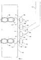
- FIG. 3is a front view of the apparatus for installing a satellite dish to a pole in accordance with an embodiment of the present invention.
- FIG. 4is a side view of a satellite dish antenna that is connected to a mast of the apparatus in accordance with an embodiment of the present invention.
- drawingsuse a nomenclature for reference numerals that has two parts.
- the first part of the reference numeralis the drawing number, and it is followed by the second part, a two-digit identifier (drawing 1 uses 1 xx; drawing 3 uses 3 xx).
- two reference numerals in drawing 1may be “ 102 ” and “ 104 .”
- a reference numeral in one drawingmay be referred to in subsequent drawings; the same reference numeral in later drawings refers to the same item.
- FIGS. 1-3show the mounting apparatus.
- FIG. 1shows a top-down view
- FIG. 2shows a side view
- FIG. 3shows a front view of the apparatus.
- FIG. 4shows a side view of a satellite dish antenna that is connected to the mast of the mounting apparatus.
- the apparatusmay include a vertical member 104 , one or more cross members 106 , one or more chains 108 , and one or more dish mount mates 202 .
- the different components of the apparatusmay be made from various materials, such as plastics, graphite, and aluminum. Preferably, the components would be made from steel.
- the vertical memberis placed against the pole 102 in a lengthwise orientation. This orientation is best seen in FIG. 2 .
- the vertical member 104may be flat or have another shape.
- the vertical member 104may have a concave back. This concave shape of the vertical member 104 provides two ridges that contact the curved surface of the pole. Thus, the two ridges may provide a stable contact against the pole and may prevent rolling of the vertical member 104 .
- the vertical member 104may include other forms to help provide a stable contact against the pole, including, but not limited to, a rubberized or metallic treaded back or adhesives.
- One or more cross members 106may be connected to the vertical member 104 .
- the cross members 106may be welded to the vertical member 104 .
- bolting, gluing, or other attachment of the cross member 106may be possible.
- the cross member 106may be designed with different shapes, the rectangular beam may be the simplest shape to make or use.
- the cross member 106should be of sufficient length to allow the chain 108 to be attached and wrapped around the pole 102 .
- the cross member 106is shown at the ends of the vertical member 104 . However, the placement of the cross members 106 may be at any point along the length of the vertical member 104 . A perpendicular orientation to the vertical member 104 is also preferred, but not required.
- a chain 108is attached to the cross members 106 .
- the chain 108may be attached using eye bolts 110 .
- eye bolts 110may be inserted through holes 120 placed in the cross member 106 .
- a washer 114 and bolt 112may be placed on one or more sides of the cross member 106 to hold the eyebolt 110 .
- the depth of insertion of the eye bolt 110may be adjusted. Adjustment may be accomplished by changing where the bolts 112 are placed along the eyebolt 110 .
- the bolts 112may be screwed further up the shank of the eyebolt 110 .
- the chain 108may be tightened. Having two eyebolts 110 may allow for the chain 108 to be tightened or loosened to a greater extent.
- one end of the chain 108may be welded or attached without an eyebolt 110 .
- the chain 108is wrapped around the pole 102 .
- the chain 108may span the opposite side of the pole 102 from the vertical member 104 .
- the pole 102is between the vertical member 104 and the chain 108 .
- the apparatusincludes a dish mounting mate 202 .
- the dish mounting mate 202may be a plate that can mate with the foot 116 .
- the matecomprises a pair of two mounting members 202 . These mounting members 202 may be separated by a sufficient distance to accommodate the satellite foot 116 .
- Bolts 204 that are used to attach the foot 116 to the mounting members 202may be inserted through the mounting members 202 and nuts 112 .
- the foot 116may then hold the mast 118 , which secures the satellite dish 402 , feedhorn 404 , and low noise block filter (LNBF) 406 .
- LNBFlow noise block filter
- the mast 118may be secured by the mast 118 .
- the installation of a satellite dishoften requires pointing the satellite dish towards the signals transmitted by one or more satellites. Pointing the satellite dish may require adjusting the azimuth and elevation of the satellite dish.
- the mast 118In order to get accurate azimuth and elevation for the satellite dish, the mast 118 must be oriented vertically to the horizon in all directions. To achieve this vertical orientation, in this preferred embodiment, the mast 118 may pivot to achieve vertical orientation with respect to a first axis. Additionally, bolts 204 can be used to achieve vertical orientation with respect to a second axis which is perpendicular to the first.
- mast 118is vertically oriented with good accuracy.
- the satellite antennacan be placed on it.
- the antennawill be preset with an appropriate elevation and the installer can then swing the antenna through various azimuth angles until the satellite is found.
- a vertical member 104may also include, but is not limited to, metallic treads, rubberized treads or an adhesive backing. Numerous other changes may be made which will readily suggest themselves to those skilled in the art and which are encompassed in the spirit of the invention disclosed and as defined in the appended claims.
Landscapes
- Support Of Aerials (AREA)
Abstract
Description
Claims (22)
Priority Applications (1)
| Application Number | Priority Date | Filing Date | Title |
|---|---|---|---|
| US11/757,862US7460081B2 (en) | 2003-09-24 | 2007-06-04 | Apparatus and method for mounting a satellite dish to a pole |
Applications Claiming Priority (4)
| Application Number | Priority Date | Filing Date | Title |
|---|---|---|---|
| US56073303P | 2003-09-24 | 2003-09-24 | |
| US10/949,617US7027006B2 (en) | 2003-09-24 | 2004-09-23 | Apparatus and method for mounting a satellite dish to a pole |
| US11/366,049US7253785B2 (en) | 2003-09-24 | 2006-03-01 | Apparatus and method for mounting a satellite dish to a pole |
| US11/757,862US7460081B2 (en) | 2003-09-24 | 2007-06-04 | Apparatus and method for mounting a satellite dish to a pole |
Related Parent Applications (1)
| Application Number | Title | Priority Date | Filing Date |
|---|---|---|---|
| US11/366,049ContinuationUS7253785B2 (en) | 2003-09-24 | 2006-03-01 | Apparatus and method for mounting a satellite dish to a pole |
Publications (2)
| Publication Number | Publication Date |
|---|---|
| US20070241247A1 US20070241247A1 (en) | 2007-10-18 |
| US7460081B2true US7460081B2 (en) | 2008-12-02 |
Family
ID=34556594
Family Applications (3)
| Application Number | Title | Priority Date | Filing Date |
|---|---|---|---|
| US10/949,617Expired - LifetimeUS7027006B2 (en) | 2003-09-24 | 2004-09-23 | Apparatus and method for mounting a satellite dish to a pole |
| US11/366,049Expired - LifetimeUS7253785B2 (en) | 2003-09-24 | 2006-03-01 | Apparatus and method for mounting a satellite dish to a pole |
| US11/757,862Expired - Fee RelatedUS7460081B2 (en) | 2003-09-24 | 2007-06-04 | Apparatus and method for mounting a satellite dish to a pole |
Family Applications Before (2)
| Application Number | Title | Priority Date | Filing Date |
|---|---|---|---|
| US10/949,617Expired - LifetimeUS7027006B2 (en) | 2003-09-24 | 2004-09-23 | Apparatus and method for mounting a satellite dish to a pole |
| US11/366,049Expired - LifetimeUS7253785B2 (en) | 2003-09-24 | 2006-03-01 | Apparatus and method for mounting a satellite dish to a pole |
Country Status (1)
| Country | Link |
|---|---|
| US (3) | US7027006B2 (en) |
Cited By (10)
| Publication number | Priority date | Publication date | Assignee | Title |
|---|---|---|---|---|
| US20110032172A1 (en)* | 2009-08-04 | 2011-02-10 | Echostar Technologies L.L.C. | Nonconductive antenna mount |
| US20110083399A1 (en)* | 2009-10-13 | 2011-04-14 | Dish Network L.L.C. | Structures and methods for mounting an object |
| US8698692B2 (en) | 2010-02-23 | 2014-04-15 | Dish Network L.L.C. | Apparatus for mounting an object to a railing |
| US8780008B2 (en) | 2008-06-20 | 2014-07-15 | Dish Network L.L.C. | Reinforced mount for an antenna assembly |
| US8802985B2 (en) | 2011-09-07 | 2014-08-12 | Dish Network L.L.C. | In-wall extension apparatus |
| US8819743B2 (en) | 2007-12-19 | 2014-08-26 | Dish Network L.L.C. | Transfer of data related to broadcast programming over a communication network |
| US8907862B2 (en) | 2011-04-12 | 2014-12-09 | Dish Network L.L.C. | Apparatus and systems for mounting an electrical switching device |
| US9123987B2 (en) | 2012-07-31 | 2015-09-01 | Dish Network L.L.C. | Antenna mounting systems and methods |
| US9337545B2 (en) | 2008-06-20 | 2016-05-10 | Dish Network L.L.C. | Apparatus and systems for mounting an electrical switching device |
| USD901460S1 (en)* | 2013-06-05 | 2020-11-10 | Loon Llc | Terrestrial unit for connectivity to a balloon network |
Families Citing this family (6)
| Publication number | Priority date | Publication date | Assignee | Title |
|---|---|---|---|---|
| US7027006B2 (en)* | 2003-09-24 | 2006-04-11 | Echostar Technologies Corporation | Apparatus and method for mounting a satellite dish to a pole |
| US20110109501A1 (en)* | 2009-11-06 | 2011-05-12 | Viasat, Inc. | Automated beam peaking satellite ground terminal |
| US20110133045A1 (en)* | 2009-12-07 | 2011-06-09 | Brian Donald Merle Sorum | Tree stand support system |
| US9553350B2 (en)* | 2015-05-14 | 2017-01-24 | Micro Wireless Solutions, Corp. | Antenna mount assembly |
| SE540650C2 (en)* | 2016-09-22 | 2018-10-09 | Cue Dee Ab | Chain clamp |
| GB2579977B8 (en)* | 2017-08-15 | 2023-07-19 | Commscope Design & Integration Uk Ltd | Antenna mounting bracket assembly |
Citations (3)
| Publication number | Priority date | Publication date | Assignee | Title |
|---|---|---|---|---|
| US4598297A (en)* | 1983-10-21 | 1986-07-01 | Hawkins Joel W | Mounting apparatus for satellite dish antennas |
| US6450464B1 (en)* | 2001-01-12 | 2002-09-17 | Elbert Lee Thomas | Satellite dish stand |
| US7253785B2 (en)* | 2003-09-24 | 2007-08-07 | Echostar Technologies Corporation | Apparatus and method for mounting a satellite dish to a pole |
Family Cites Families (6)
| Publication number | Priority date | Publication date | Assignee | Title |
|---|---|---|---|---|
| US5617680A (en)* | 1994-07-21 | 1997-04-08 | Beatty; Douglas | Mounting structure for a satellite dish |
| US5886673A (en)* | 1996-06-04 | 1999-03-23 | Thomas; Pat | Apparatus and method for improving portability of satellite antennas |
| US6396459B1 (en)* | 2001-06-14 | 2002-05-28 | Timothy A. Pullman | Easy trim dish mount |
| US6727861B2 (en)* | 2001-12-31 | 2004-04-27 | Satellite Accessories, Llc | Satellite antenna mounting apparatus and method |
| US6734830B1 (en)* | 2002-09-27 | 2004-05-11 | Comazell Bickham | Portable adjustable stand for satellite dish antennas |
| US6731250B1 (en)* | 2002-12-10 | 2004-05-04 | Elliot Berman | Movable window support device for a satellite TV dish |
- 2004
- 2004-09-23USUS10/949,617patent/US7027006B2/ennot_activeExpired - Lifetime
- 2006
- 2006-03-01USUS11/366,049patent/US7253785B2/ennot_activeExpired - Lifetime
- 2007
- 2007-06-04USUS11/757,862patent/US7460081B2/ennot_activeExpired - Fee Related
Patent Citations (3)
| Publication number | Priority date | Publication date | Assignee | Title |
|---|---|---|---|---|
| US4598297A (en)* | 1983-10-21 | 1986-07-01 | Hawkins Joel W | Mounting apparatus for satellite dish antennas |
| US6450464B1 (en)* | 2001-01-12 | 2002-09-17 | Elbert Lee Thomas | Satellite dish stand |
| US7253785B2 (en)* | 2003-09-24 | 2007-08-07 | Echostar Technologies Corporation | Apparatus and method for mounting a satellite dish to a pole |
Non-Patent Citations (1)
| Title |
|---|
| Locon Treestands LLC, Treestand Manual, 2 pages, Locon Treestands LLC, Waterford, Ohio 45786, www.locontreestandsllc.com, no date. |
Cited By (16)
| Publication number | Priority date | Publication date | Assignee | Title |
|---|---|---|---|---|
| US9226031B2 (en) | 2007-12-19 | 2015-12-29 | Dish Network L.L.C. | Transfer of data related to broadcast programming over a communication network |
| US9596506B2 (en) | 2007-12-19 | 2017-03-14 | Dish Network L.L.C. | Transfer of data related to broadcast programming over a communication network |
| US8819743B2 (en) | 2007-12-19 | 2014-08-26 | Dish Network L.L.C. | Transfer of data related to broadcast programming over a communication network |
| US8780008B2 (en) | 2008-06-20 | 2014-07-15 | Dish Network L.L.C. | Reinforced mount for an antenna assembly |
| US9337545B2 (en) | 2008-06-20 | 2016-05-10 | Dish Network L.L.C. | Apparatus and systems for mounting an electrical switching device |
| US8531347B2 (en) | 2009-08-04 | 2013-09-10 | Echostar Technologies L.L.C. | Nonconductive antenna mount |
| US20110032172A1 (en)* | 2009-08-04 | 2011-02-10 | Echostar Technologies L.L.C. | Nonconductive antenna mount |
| US20110083399A1 (en)* | 2009-10-13 | 2011-04-14 | Dish Network L.L.C. | Structures and methods for mounting an object |
| US8698692B2 (en) | 2010-02-23 | 2014-04-15 | Dish Network L.L.C. | Apparatus for mounting an object to a railing |
| US8907862B2 (en) | 2011-04-12 | 2014-12-09 | Dish Network L.L.C. | Apparatus and systems for mounting an electrical switching device |
| US9502875B2 (en) | 2011-09-07 | 2016-11-22 | Dish Network L.L.C. | In-wall extension apparatus |
| US9178291B2 (en) | 2011-09-07 | 2015-11-03 | Dish Network L.L.C. | In-wall extension apparatus |
| US8802985B2 (en) | 2011-09-07 | 2014-08-12 | Dish Network L.L.C. | In-wall extension apparatus |
| US9929553B2 (en) | 2011-09-07 | 2018-03-27 | Dish Network L.L.C. | In-wall extension apparatus |
| US9123987B2 (en) | 2012-07-31 | 2015-09-01 | Dish Network L.L.C. | Antenna mounting systems and methods |
| USD901460S1 (en)* | 2013-06-05 | 2020-11-10 | Loon Llc | Terrestrial unit for connectivity to a balloon network |
Also Published As
| Publication number | Publication date |
|---|---|
| US7253785B2 (en) | 2007-08-07 |
| US20060145939A1 (en) | 2006-07-06 |
| US20070241247A1 (en) | 2007-10-18 |
| US20050093763A1 (en) | 2005-05-05 |
| US7027006B2 (en) | 2006-04-11 |
Similar Documents
| Publication | Publication Date | Title |
|---|---|---|
| US7460081B2 (en) | Apparatus and method for mounting a satellite dish to a pole | |
| US4595165A (en) | Adjustable anchoring assembly | |
| US4723128A (en) | Roof mount for dish antenna | |
| US8780008B2 (en) | Reinforced mount for an antenna assembly | |
| US5566916A (en) | Adjustable pipe brace | |
| US7683853B2 (en) | Non-invasive antenna mount | |
| US20110083399A1 (en) | Structures and methods for mounting an object | |
| US5604508A (en) | Antenna assembly and interface bracket for satellite and terrestrial antennas | |
| US6195066B1 (en) | Satellite dish mounting arm | |
| US6709184B1 (en) | Apparatus for mounting a receiver mast and associated method | |
| US20100066633A1 (en) | Variable angle mount for attaching a mast to a structure | |
| US4181284A (en) | Antenna bracket for exterior walls | |
| JP4340827B2 (en) | ANTENNA MOUNTING DEVICE, ITS MOUNTING METHOD, AND SATELLITE RADIO RECEIVE ANTENNA DEVICE | |
| US4510502A (en) | Dish antennae mounting structure | |
| US5687938A (en) | Adjustable pipe brace | |
| US9337545B2 (en) | Apparatus and systems for mounting an electrical switching device | |
| US6762731B1 (en) | Dish antenna rotation apparatus | |
| US6480172B1 (en) | Adjustable antenna mounting apparatus | |
| US20070273598A1 (en) | Luneberg Lens Antenna Device | |
| JP4426043B2 (en) | Antenna support device | |
| US9620845B1 (en) | Bracket for antenna attachment | |
| US4605333A (en) | Dish antennae mounting structure | |
| US20070144105A1 (en) | Mounting bracket for roof-top structures | |
| JPS61194901A (en) | Antenna supporting system for mounting on roof | |
| US4612552A (en) | Dish antennae mounting structure |
Legal Events
| Date | Code | Title | Description |
|---|---|---|---|
| FEPP | Fee payment procedure | Free format text:PAYOR NUMBER ASSIGNED (ORIGINAL EVENT CODE: ASPN); ENTITY STATUS OF PATENT OWNER: LARGE ENTITY | |
| AS | Assignment | Owner name:ECHOSTAR TECHNOLOGIES L.L.C., COLORADO Free format text:CHANGE OF NAME;ASSIGNOR:ECHOSTAR TECHNOLOGIES CORP.;REEL/FRAME:021754/0816 Effective date:20071231 | |
| AS | Assignment | Owner name:ECHOSTAR TECHNOLOGIES CORP., COLORADO Free format text:ASSIGNMENT OF ASSIGNORS INTEREST;ASSIGNOR:HOLLE, KEVIN S.;REEL/FRAME:021774/0143 Effective date:20041223 | |
| STCF | Information on status: patent grant | Free format text:PATENTED CASE | |
| FEPP | Fee payment procedure | Free format text:PAYOR NUMBER ASSIGNED (ORIGINAL EVENT CODE: ASPN); ENTITY STATUS OF PATENT OWNER: LARGE ENTITY Free format text:PAYER NUMBER DE-ASSIGNED (ORIGINAL EVENT CODE: RMPN); ENTITY STATUS OF PATENT OWNER: LARGE ENTITY | |
| FPAY | Fee payment | Year of fee payment:4 | |
| FPAY | Fee payment | Year of fee payment:8 | |
| AS | Assignment | Owner name:DISH TECHNOLOGIES L.L.C., COLORADO Free format text:CHANGE OF NAME;ASSIGNOR:ECHOSTAR TECHNOLOGIES L.L.C.;REEL/FRAME:047264/0127 Effective date:20180202 | |
| FEPP | Fee payment procedure | Free format text:MAINTENANCE FEE REMINDER MAILED (ORIGINAL EVENT CODE: REM.); ENTITY STATUS OF PATENT OWNER: LARGE ENTITY | |
| LAPS | Lapse for failure to pay maintenance fees | Free format text:PATENT EXPIRED FOR FAILURE TO PAY MAINTENANCE FEES (ORIGINAL EVENT CODE: EXP.); ENTITY STATUS OF PATENT OWNER: LARGE ENTITY | |
| STCH | Information on status: patent discontinuation | Free format text:PATENT EXPIRED DUE TO NONPAYMENT OF MAINTENANCE FEES UNDER 37 CFR 1.362 | |
| FP | Lapsed due to failure to pay maintenance fee | Effective date:20201202 |