US7459834B2 - Solid state gimbal system - Google Patents
Solid state gimbal systemDownload PDFInfo
- Publication number
- US7459834B2 US7459834B2US11/472,673US47267306AUS7459834B2US 7459834 B2US7459834 B2US 7459834B2US 47267306 AUS47267306 AUS 47267306AUS 7459834 B2US7459834 B2US 7459834B2
- Authority
- US
- United States
- Prior art keywords
- curvilinear
- solid state
- gimbal
- gimbal system
- actuators
- Prior art date
- Legal status (The legal status is an assumption and is not a legal conclusion. Google has not performed a legal analysis and makes no representation as to the accuracy of the status listed.)
- Expired - Fee Related, expires
Links
- 239000007787solidSubstances0.000titleclaimsdescription28
- 230000003287optical effectEffects0.000claimsdescription25
- 238000004891communicationMethods0.000abstractdescription3
- 239000000919ceramicSubstances0.000description24
- 238000000034methodMethods0.000description12
- 239000000463materialSubstances0.000description7
- 239000003990capacitorSubstances0.000description6
- 230000008878couplingEffects0.000description6
- 238000010168coupling processMethods0.000description6
- 238000005859coupling reactionMethods0.000description6
- 238000010586diagramMethods0.000description6
- PXHVJJICTQNCMI-UHFFFAOYSA-NNickelChemical compound[Ni]PXHVJJICTQNCMI-UHFFFAOYSA-N0.000description5
- 230000001419dependent effectEffects0.000description5
- 238000005452bendingMethods0.000description4
- 230000006835compressionEffects0.000description4
- 238000007906compressionMethods0.000description4
- 238000012937correctionMethods0.000description4
- 230000008569processEffects0.000description4
- 238000013459approachMethods0.000description3
- 238000005516engineering processMethods0.000description3
- 238000004519manufacturing processMethods0.000description3
- 239000002184metalSubstances0.000description3
- 229910052751metalInorganic materials0.000description3
- 238000005245sinteringMethods0.000description3
- 238000003860storageMethods0.000description3
- MCMNRKCIXSYSNV-UHFFFAOYSA-NZirconium dioxideChemical compoundO=[Zr]=OMCMNRKCIXSYSNV-UHFFFAOYSA-N0.000description2
- 238000003491arrayMethods0.000description2
- 230000008901benefitEffects0.000description2
- 238000000151depositionMethods0.000description2
- 230000000694effectsEffects0.000description2
- 238000003754machiningMethods0.000description2
- KDLHZDBZIXYQEI-UHFFFAOYSA-NpalladiumSubstances[Pd]KDLHZDBZIXYQEI-UHFFFAOYSA-N0.000description2
- 230000004044responseEffects0.000description2
- 238000005070samplingMethods0.000description2
- 238000013519translationMethods0.000description2
- 230000000007visual effectEffects0.000description2
- 229910000661Mercury cadmium tellurideInorganic materials0.000description1
- 241001465754MetazoaSpecies0.000description1
- 101150003085Pdcl geneProteins0.000description1
- XUIMIQQOPSSXEZ-UHFFFAOYSA-NSiliconChemical compound[Si]XUIMIQQOPSSXEZ-UHFFFAOYSA-N0.000description1
- 230000003044adaptive effectEffects0.000description1
- 239000011230binding agentSubstances0.000description1
- 230000015556catabolic processEffects0.000description1
- 230000008859changeEffects0.000description1
- 239000002131composite materialSubstances0.000description1
- 150000001875compoundsChemical class0.000description1
- 238000010276constructionMethods0.000description1
- 238000007796conventional methodMethods0.000description1
- 238000013016dampingMethods0.000description1
- 230000007123defenseEffects0.000description1
- 238000000280densificationMethods0.000description1
- 238000013461designMethods0.000description1
- 230000009977dual effectEffects0.000description1
- 230000005684electric fieldEffects0.000description1
- 238000005530etchingMethods0.000description1
- 238000001125extrusionMethods0.000description1
- 238000003384imaging methodMethods0.000description1
- 238000003331infrared imagingMethods0.000description1
- 238000001746injection mouldingMethods0.000description1
- 238000003780insertionMethods0.000description1
- 230000037431insertionEffects0.000description1
- 239000004973liquid crystal related substanceSubstances0.000description1
- 238000001459lithographyMethods0.000description1
- 230000014759maintenance of locationEffects0.000description1
- 239000000203mixtureSubstances0.000description1
- 229910052759nickelInorganic materials0.000description1
- 239000012811non-conductive materialSubstances0.000description1
- 239000003921oilSubstances0.000description1
- 238000004806packaging method and processMethods0.000description1
- 239000003973paintSubstances0.000description1
- SWELZOZIOHGSPA-UHFFFAOYSA-Npalladium silverChemical compound[Pd].[Ag]SWELZOZIOHGSPA-UHFFFAOYSA-N0.000description1
- 238000007747platingMethods0.000description1
- 229920000642polymerPolymers0.000description1
- -1polytetrafluoroethylenePolymers0.000description1
- 229920001343polytetrafluoroethylenePolymers0.000description1
- 239000004810polytetrafluoroethyleneSubstances0.000description1
- 238000012545processingMethods0.000description1
- 238000011160researchMethods0.000description1
- 238000012827research and developmentMethods0.000description1
- 229910052710siliconInorganic materials0.000description1
- 239000010703siliconSubstances0.000description1
- 239000007779soft materialSubstances0.000description1
Images

Classifications
- H—ELECTRICITY
- H10—SEMICONDUCTOR DEVICES; ELECTRIC SOLID-STATE DEVICES NOT OTHERWISE PROVIDED FOR
- H10N—ELECTRIC SOLID-STATE DEVICES NOT OTHERWISE PROVIDED FOR
- H10N30/00—Piezoelectric or electrostrictive devices
- H10N30/20—Piezoelectric or electrostrictive devices with electrical input and mechanical output, e.g. functioning as actuators or vibrators
- H10N30/208—Piezoelectric or electrostrictive devices with electrical input and mechanical output, e.g. functioning as actuators or vibrators using shear or torsion displacement, e.g. d15 type devices
- H—ELECTRICITY
- H02—GENERATION; CONVERSION OR DISTRIBUTION OF ELECTRIC POWER
- H02N—ELECTRIC MACHINES NOT OTHERWISE PROVIDED FOR
- H02N2/00—Electric machines in general using piezoelectric effect, electrostriction or magnetostriction
- H02N2/10—Electric machines in general using piezoelectric effect, electrostriction or magnetostriction producing rotary motion, e.g. rotary motors
- H02N2/108—Electric machines in general using piezoelectric effect, electrostriction or magnetostriction producing rotary motion, e.g. rotary motors around multiple axes of rotation, e.g. spherical rotor motors
- B—PERFORMING OPERATIONS; TRANSPORTING
- B33—ADDITIVE MANUFACTURING TECHNOLOGY
- B33Y—ADDITIVE MANUFACTURING, i.e. MANUFACTURING OF THREE-DIMENSIONAL [3-D] OBJECTS BY ADDITIVE DEPOSITION, ADDITIVE AGGLOMERATION OR ADDITIVE LAYERING, e.g. BY 3-D PRINTING, STEREOLITHOGRAPHY OR SELECTIVE LASER SINTERING
- B33Y80/00—Products made by additive manufacturing
Definitions
- the invention disclosed hereinwas supported, at least in part, by a grant from the Defense Advance Research Projects Agency (DARPA) under DARPA Order No. S039-38 issued by the U.S. Army Aviation and Missile Command under Contract No. W31P4Q-05-C-0180.
- DRPADefense Advance Research Projects Agency
- the Governmenthas certain limited rights to at least one form of the invention.
- the present inventiongenerally relates to a gimbal system.
- the inventionis a lightweight, robust gimbal actively controllable via curvilinear piezo-actuators operating in the shear mode which directly contact and rotate a spherical-shaped element within a like-shaped housing.
- Games, toys, weapons and communication systemstypically couple an acoustic-based device, a light-based device, an imaging device or the like to hardware for the purpose of transmitting, recording, detecting, classifying, and/or tracking.
- Presently known devicesare aimed by a variety of steering methods.
- Altitude-azimuth steering systemsare typically composed of gyroscopes, motors, rings, and bearings.
- Exemplary systemsinclude a gyroscope and mechanically complicated inner and outer gimbal elements, so as to achieve tilt within a range limited by the size of components within and packaging of the system.
- altitude-azimuth systemsare inherently complex, costly, and heavy.
- componentsare susceptible to stiction, fretting, and friction, which limit and frustrate the translation of any device mounted to the gimbal.
- Waveguide steeringincludes various approaches.
- an array of actuatorsmight translate a microlens array along orthogonal lateral directions.
- Large two-dimensional lenslet arraysare possible wherein pixels are independently controlled.
- liquid crystal optical phase arraysLC-OPAs
- Nishimura et al.in U.S. Pat. No. 6,734,914, describes and claims an image recording unit permitting 360 degrees of rotation.
- the deviceincludes four sets of piezoelectric elements, a rotary unit fixing frame, and a spherical rotary unit.
- Piezoelectric elementsoperate in the longitudinal mode, whereby each linear rectangular actuator is electrically poled and driven through its thickness, referred to as the d 33 mode, or is electrically poled through its thickness and driven along its length, referred to as the d 31 mode.
- the spherical rotary unitcontacts and presses against the fixing frame.
- Piezoelectric elementsare arranged and electrically activated in a pair-wise fashion so that a traveling wave is formed in the fixing frame around either the Y-axis and/or X-axis. Thereafter, the fixing frame exhibits motion which is communicated to the spherical rotary unit so as to frictionally drive the rotary unit. As such, the piezoelectric elements do not directly drive the spherical rotary unit.
- Johanssonin U.S. Pat. No. 6,437,485, describes and claims a double bimorph electromechanical element capable of rotating an element via bending motion along the piezoelectric device.
- the related artsdo not provide a gimbal device capable of rapidly rotating a sphere via the direct contact by curvilinear actuators comprised of a piezoelectric material operating in the shear mode, also referred to as d 12 , d 14 , d 15 , or d 16 mode.
- An object of the present inventionis to provide a lightweight, low-volume, and mechanically simple gimbal device which provides for the direct rotational drive of a spherical element by curvilinear piezoelectric actuators operating in the shear mode.
- a rotatable sphereis accurately rotated and positioned within a gimbal housing by four non-bimorph piezoelectric actuators.
- Piezoelectric actuatorsoperate in a shear mode (such as d 15 ) rather than a longitudinal mode (d 31 or d 33 ).
- Shear mode motionincludes both linear and bending components within the same piezoelectric material.
- the shear modeis achieved by a combination of two voltage directions whereby a piezo-ceramic is poled from end to end along the longest length of the actuator and electrically powered via electrodes disposed about the thickness of the same actuator.
- Shear mode actuatorsensure greater electromechanical coupling and as such are capable of directly driving the rotatable sphere.
- the present inventionis a modular solid state gimbal system comprised of a gimbal housing, including hemispherical and annular caps, rotatable sphere, and at least two curvilinear actuators.
- the hemispherical capis attached to the annular cap in a removable fashion so as to surround the rotatable sphere.
- the rotatable spherehas a radius of curvature less than that of the gimbal housing.
- Curvilinear actuatorsare disposed between the rotatable sphere and gimbal housing. Curvilinear actuators rotate the rotatable sphere, via shear induced motion, with respect to the interior surface of the gimbal housing.
- Hemispherical and annular capsare dimensionally sized to compress the curvilinear actuators against the rotatable sphere.
- An acoustic, light, or optical devicemay be attached to the rotatable sphere so as to allow precision aiming of the device at a high angular rate over a wide acceptance angle.
- the present inventionis scalable for use within many applications, including MEMS.
- the present inventionrequires substantially less power than mechanically actuated gimbals.
- the present inventionhas substantially less moving parts than mechanically actuated gimbals, thereby providing higher operational reliability.
- the present inventionis lighter and smaller than mechanically actuated gimbals.
- the present inventionenables a large field of view over a wide acceptance angle with higher angular rotation rates and precision than mechanically actuated gimbals.
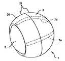
- FIG. 1is a perspective view showing one embodiment of the solid state gimbal system for the present invention.
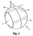
- FIG. 2is a cross sectional view of the present invention showing the solid state gimbal system including a gimbal housing comprised of a lower hemispherical cap and an upper annular cap mutually attached and surrounding a rotatable sphere with four curvilinear actuators disposed between and compressed by the sphere and housing.
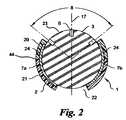
- FIG. 3is an exploded section view of the gimbal system embodiment described in FIGS. 1 and 2 .
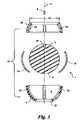
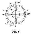
- FIG. 4is a top view of the gimbal system shown in FIGS. 1 and 2 without rotatable sphere showing the paired and opposed arrangement of curvilinear actuators along both the X-axis and the Y-axis.
- FIG. 5is an enlarged section view of the hemispherical cap showing exemplary curvilinear actuators composed of a piezoelectric layer disposed between a pair of electrodes.
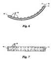
- FIG. 6is a side view of an alternate embodiment for the curvilinear actuators having a plurality of protrusions outwardly disposed along and projecting from one electrode.
- FIG. 7is a top view of the curvilinear actuator in FIG. 6 showing a row-column arrangement of protrusions.
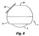
- FIG. 8shows a side elevation view of the solid state gimbal system having an optical tracker attached to the gimbal housing adjacent to the opening at the back end of the gimbal housing.
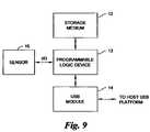
- FIG. 9is a block diagram for an exemplary embodiment showing data acquisition from a sensor attached to the gimbal system.
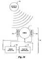
- FIG. 10is a schematic block diagram for an exemplary application of the present invention within an acoustic tracking system.
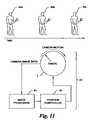
- FIG. 11is a schematic block diagram for an exemplary application of the present invention within an optical tracking system.
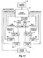
- FIG. 12is a block diagram for an exemplary application of the present invention including a joystick used to control the position of the rotatable sphere within the gimbal system.
- the gimbal system 1is shown in a perspective view including a rotatable sphere 3 disposed within a gimbal housing 21 , comprising a hemispherical cap 2 and an annular cap 20 , with at least two curvilinear actuators 7 a , 7 d (actuators 7 b and 7 c not shown) disposed between the rotatable sphere 3 and gimbal housing 21 .
- the rotatable sphere 3 and gimbal housing 21are dimensioned so as to form a press or compression fit with the curvilinear actuators 7 a - 7 d sufficiently to fix the rotatable sphere 3 in a specific orientation when the curvilinear actuators 7 a - 7 d are electrically inactive. It is also required for the press or compression fit to allow rotation of the rotatable sphere 3 when the curvilinear actuators 7 a - 7 d are activated by an electric field.
- the gimbal system 1is shown in more detail comprised of a hemispherical cap 2 , an annular cap 20 , curvilinear actuators 7 a - 7 d , and a rotatable sphere 3 .
- Hemispherical cap 2 , rotatable sphere 3 , and annular cap 20are preferred to be composed of dimensionally stable and non-conductive materials, non-limiting examples including polymers and composites.
- the rotatable sphere 3may include a dense metal insert to increase its total mass without compromising the non-conductive nature of the element.
- the gimbal housing 21may be fabricated via conventional manufacturing methods, including machining, stereo lithography, injection molding, and extrusion.
- Curvilinear actuators 7 a , 7 bare generally composed of a piezoelectric material, preferably a piezoceramic, one example being PZT, disposed between a pair of electrically conductive elements, preferably composed of a metal. Conventional methods are also applicable to the fabrication, poling, and electroding of curvilinear actuators 7 a - 7 d.
- the gimbal housing 21is composed of a two-piece construction, namely, hemispherical cap 2 and annular cap 20 , so as to facilitate assembly of the rotatable sphere 3 and curvilinear actuators 7 a - 7 d into the interior cavity of the gimbal system 1 .
- the annular cap 20may be mechanically or adhesively fastened to the hemispherical cap 2 along a mutually aligned and contacting seam 44 or flange arrangement.
- the location of the seam 44must provide an opening of sufficient diameter so as to allow insertion of the rotatable sphere 3 into the gimbal housing 21 .
- the interior contour of the gimbal housing 21is preferred to be spherically shaped and dimensionally larger than the diameter of the rotatable sphere 3 .
- Curvilinear actuators 7 a - 7 dare generally described as elongated elements disposed in a radial fashion about the central axis 17 and contacting both hemispherical cap 2 and annular cap 20 along a first surface and the rotatable sphere 3 along a second surface.
- Each curvilinear actuator 7 a - 7 dcontacts the interior of the hemispherical cap 2 beginning at the seam 44 and ending adjacent to opening 22 which resides at the bottom of the hemispherical cap 2 .
- each curvilinear actuator 7 a - 7 dcontacts the interior of the annular cap 20 beginning at the seam 44 and ending adjacent to the opening 23 at the top of the annular cap 20 .
- each curvilinear actuator 7 a - 7 dwas preferred for each curvilinear actuator 7 a - 7 d to sufficiently long so as to provide an arc with a total angle from 80 to 90 degrees.
- the curvilinear actuators 7 a - 7 dit was preferred for the curvilinear actuators 7 a - 7 d to exhibit both bending mode and shear mode vibrations.
- the coupling of these two modeswas found to be dependent on the length-to-thickness ratio of the curvilinear actuators 7 a - 7 d . While mode coupling is possible over a variety of length-to-thickness ratios, coupled modes were achieved in a traveling wave along the curvilinear actuators 7 a - 7 d at a ratio equal to 12.
- the opening 23 within the annular cap 20 and opening 22 within the hemispherical cap 2are preferred to be circular shaped and symmetrically disposed about the central axis 17 .
- the diameter of the opening 23determines the field of view 8 for a device 6 attached to or within the support cavity 16 which is provided within the rotatable sphere 3 adjacent to the opening 23 . It was preferred for the opening 23 to have a total angle of 110 degrees, although other values are possible.
- the gimbal housing 21is preferred to include channels 24 which are dimensioned so as to sufficiently accommodate the length and width of the curvilinear actuators 7 a - 7 d , so as to support the curvilinear actuators 7 a - 7 d in a non-binding fashion.
- the depth of each channel 24should be less than the thickness of the curvilinear actuators 7 a - 7 d so that the curvilinear actuators 7 a - 7 d extend into the interior cavity of the gimbal housing 21 .
- the spherical ball 3is supported within the structure formed by the hemispherical cap 2 and annular cap 20 so as to compress the curvilinear actuators 7 a - 7 d . Compression of the curvilinear actuators 7 a - 7 d couples shear induced motion within the curvilinear actuators 7 a - 7 d to rotational motion of the spherical ball 3 about the field of view 8 .
- ris +d c ⁇ t ca ⁇ r rs
- ris the radius of the interior surface of the gimbal housing 21
- d cis the depth of the channel 24
- t cais the thickness of the curvilinear actuator 7 a - 7 b
- r rsis the radius of the rotatable sphere 3 .
- the hemispherical cap 2is shown with a socket 4 therein; although, other generally symmetrical shapes about a central axis 17 are likewise possible.
- Curvilinear actuators 7 a - 7 dare attached to the interior surface of the hemispherical cap 2 within the socket 4 , preferably in a symmetrically disposed fashion. Each curvilinear actuator 7 a - 7 d extends beyond the seam 44 so as to ensure continued contact between the rotatable sphere 3 and both hemispherical cap 2 and annular cap 20 .
- Curvilinear actuators 7 a , 7 bare required to be shear-type devices.
- the annular cap 20is identical or nearly identical to the hemispherical cap 2 in size and cross section.
- the opening 23is provided to ensure an unobstructed field of view 8 for the device 6 attached to or within the support cavity 16 .
- the support cavity 16should be sufficiently shaped so as to allow fixed and precise attachment of the device 6 to the rotatable sphere 3 via methods understood in the art.
- the spherical ball 3is preferred to have a spherical profile 5 .
- the spherical profile 5should match or nearly match the contour of the curvilinear actuators 7 a - 7 d so as to ensure complete, yet slidable contact between the curvilinear actuators 7 a - 7 d and rotatable sphere 3 .
- the hemispherical cap 2is shown with two pair-wise arrangements of curvilinear actuators 7 a - 7 b and 7 c - 7 d within the socket 4 , although other arrangements are possible.
- Two curvilinear actuators 7 a , 7 bare disposed along the X-axis in a symmetric fashion.
- two curvilinear actuators 7 c and 7 dare disposed along the Y-axis in a symmetrical fashion. It is preferred for the curvilinear actuators 7 a - 7 d to be unidirectional and functionally paired, as represented by the arrows in FIG. 4 , so as to enable rotation about the Z-axis.
- curvilinear actuators 7 a and 7 dare shown functionally aligned to induce clockwise rotation of the rotatable sphere 3 ; whereas, curvilinear actuators 7 b and 7 c are arranged to induce counter-clockwise rotation of the same.
- compound rotationsare possible where X-axis and Y-axis actuators are electrically activated simultaneously or in sequence.
- Other functional arrangements and applications of the curvilinear actuators 7 a - 7 dare possible, including but not limited to a single bi-directional and unidirectional actuator disposed along the X-axis and Y-axis.
- exemplary curvilinear actuators 7 a , 7 bare shown comprised of a pair of electrodes 9 , 11 disposed about and attached to a piezoelectric layer 10 .
- the piezoelectric layer 10may be composed of one or more plates of PZT material or the like.
- Curvilinear actuators 7 a - 7 dfunction as an ultrasonic motor when energized so as to couple vibrational energy directly into the rotatable sphere 3 , thereby causing it to rotate in a preferred direction.
- the length-to-thickness ratio of the piezoelectric layer 10is tailored to optimize electromechanical coupling, so as to maximize a shear mode (such as d 15 ) rather than the longitudinal modes (d 31 or d 33 ).
- the resultant shear vibration modeproduces a corresponding bending mode thereby causing a traveling wave along the piezoelectric plate.
- Curvilinear actuators 7 a - 7 dare arc-shaped segments with a total length to achieve the desired angular coverage.
- curvilinear actuators 7 a - 7 dwere fabricated having an inner radius of 29.21 mm, an outer radius of 30.23 mm, a thickness of 1.10 mm, and a total angle of 80 degrees.
- Curvilinear actuators 7 a - 7 dwere fabricated from unfired green tape composed of hard PZT and an organic binder. The tape was cut into strips, layered, and shaped to form a green body. Dimensions of the green body were oversized based on the densification properties of the green material to account for shrinkage during sintering, which could be as large as 16%. The green body was placed onto a mold composed of zirconia having a profile which replicated the desired arc shape of the actuator. The ends of the green body were constrained so as to avoid curling during the sintering process. After sintering, the ceramic body was machined and polished to ensure the required dimensional properties.
- the shear mode material response desired in the present inventionrequired the poling orientation to be along the arc length of each ceramic body.
- a conductive paintcomprised of silver palladium (AgPd) was applied to both ends of each ceramic body and then cured at 850° C. for 15 minutes.
- the poling voltagewas generally material dependent.
- hard PZT electro-ceramicsare normally poled at 1 kV for each millimeter of length.
- a 45 kV voltagewas applied to a ceramic body having an arc length of 45 mm. It was preferred to secure the ceramic actuator body to a non-conductive planar fixture during the poling process.
- the planar fixtureincluded a pair of metal pins so as to contact the electrodes at the ends of the ceramic actuator body and to support the ceramic actuator body.
- a non-conductive pinwas also disposed along the jig and centrally located so as to contact and support the ceramic actuator body at its midpoint.
- a thin piece of polytetrafluoroethylenewas employed to wedge the ceramic actuator body tightly against the non-conductive pin.
- the fixture and ceramic actuator bodywere removed and the piezoelectric coefficient (d 33 ) was measured to determine the degree of poling.
- a 10 mm arc lengthwas cut from the ceramic actuator body so that its length was short enough compared to its radius to approximate a linear segment.
- a d 33 value of 284 pm/Vwas measured which is slightly higher than 90% of the theoretical d 33 value (315 pm/V) for the hard PZT composition. Thereafter, the end electrodes were removed.
- Electrodeswere applied to the top and bottom surfaces of the ceramic actuator body perpendicular to the poling direction to effect shear mode behavior within the actuator.
- the electroding methodwas performed at low temperature to avoid depoling of the ceramic actuator body.
- Ceramic actuator bodieswere electroded with nickel plating via a four step process.
- the poled ceramic actuators bodieswere etched in a flouroboric bath to roughen the exterior surface of the bodies and to enhance adhesion between electrodes and the ceramic.
- the ceramic actuator bodieswere immersed within a room temperature bath of SnCl dissolved in HCl to deposit a Sn layer onto the ceramic.
- the ceramic actuator bodieswere immersed within a bath containing PdCl, thus depositing a Pd layer onto the Sn layer.
- the ceramic actuator bodieswere immersed within a bath of Ni at a temperature of 70° C., thus depositing a Ni layer onto the Pd layer. Excess Ni was removed from non-electrode surfaces via a dry polished step.
- the resultant curvilinear actuators 7 a - 7 ddemonstrated a resonant frequency from 470 kHz to 475 kHz.
- an alternate curvilinear actuator 19including a piezoelectric layer 10 disposed between a pair of electrodes 9 , 11 ; however, a plurality of protrusions 18 are disposed along the outer surface of one electrode 9 .
- Protrusions 18contact the rotatable sphere 3 so as to enhance coupling of the vibration amplitude along the electrode 9 into the rotatable sphere 3 .
- Protrusions 18may include a variety of shapes including, but not limited to, squares, rectangles, circles, and hexagons.
- the protrusions 18may be implemented in an ordered arrangement consisting of two or more rows and two or more columns or a random arrangement of arbitrary shaped protrusions 18 .
- Protrusions 18are fabricated via methods understood in the art, including machining and etching.
- a curvilinear actuator 7 a - 7 d with protrusions 18is capable of a unidirectional drive speed of approximately 100 mm/sec when driven at a frequency of 340 kHz.
- One or more devices 6may be attached to the rotatable sphere 3 so as to point or otherwise project from the gimbal system 1 , as represented in FIGS. 2 and 3 .
- Devices 6may include, but are not limited to, microphones, lasers, and cameras.
- a variety of commercially available acoustic, light, and optical devicesare adaptable to the present invention.
- Optical digital micro-camera technologyis one example of devices applicable to the above described gimbal system 1 . Micro-cameras are superior to conventional digital cameras in that they offer higher image quality via mega pixel resolution, true optical zoom performance, and autofocus capability. Such devices are likewise adaptable to infrared imaging.
- Precision aiming of the device 6is dependent on the accurate tracking of the rotatable sphere 3 within the gimbal housing 21 .
- the orientation of the rotatable sphere 3 with respect to the gimbal housing 21may be determined via tracking devices and techniques for track balls.
- the track ball optical systemmodel no. HDNS-2000 sold by Agilent, Inc., includes a light-emitting diode that reflects light from a textured surface, a camera that records the reflections, and a navigation engine that processes reflections to resolve the orientation of the ball or sphere.
- FIG. 8shows one possible embodiment of the present invention, wherein a fully-integrated optical tracker 25 is mechanically fastened to the gimbal housing 21 immediately adjacent to the opening 22 .
- the optical tracker 25is arranged to project above the opening 22 as to allow the projection of a light onto the rotatable sphere 3 and recording of the projection there from.
- FIG. 9an exemplary block diagram is provided for acquisition and processing of data from a micro-camera or other sensor 15 .
- Data from the sensor 15is communicated to a programmable logic device 13 , one example being the CoolRunnerTM Series of programmable logic ICs sold by Xilinx, Inc.
- the programmable logic device 13facilitates operation of a multi-spectral digital camera within a compact chip via modifiable software to control logic gates and storage elements therein.
- the programmable logic device 13communicates with a storage medium 12 to save image data.
- the programmable logic device 13may also communicate image data from the sensor 15 to a USB module 14 , one example being a UZBEE Stinger unit sold by QorTek, Inc., for communication to a host.
- an actively controllable acoustic tracking system 34in its simplest form, is composed of a pair of acoustic receivers 31 a , 31 b electrically coupled to a phase detector 32 which is coupled to a position controller 33 , thereafter coupled to a gimbal system 1 , the latter shown and described above.
- Receivers 31 a , 31 bare commercially available devices capable of detecting sounds generated by a moving or movable target 30 , examples including but not limited to persons, animals, vehicles, objects, projectiles, and the like.
- TABLE 1identifies exemplary commercial components suited to this application of the gimbal system 1 . While two receivers 31 a , 31 b are shown, three or more such devices may be advantageous in some applications.
- Receivers 31 a , 31 bacquire acoustic emissions which are thereafter processed by the phase detector 32 , also a commercially available device. Processed emissions are then analyzed via known methods to triangulate the position of the acoustic source relative to the gimbal system 1 . Positional data is communicated to the position controller 33 which then directs the gimbal system 1 to spatially locate the device 6 attached to the rotatable sphere 3 , also described in FIGS. 2 and 3 . Sampling and correction rates of the described system are application dependent.
- an actively controllable optical tracking system 43in its simplest form, is composed of an optically-based device 6 coupled to a gimbal system 1 , as shown and described above, which is electrically coupled to an image processor 41 , and thereafter coupled to a position controller 42 which is then electrically connected to the gimbal system 1 .
- TABLE 1identifies several exemplary commercial components suited to this application of the gimbal system 1 .
- the optically-based device 6first acquires a target 40 a which is digitally mapped and recorded by the image processor 41 for tracking purposes. Subsequent images of the target 40 b and 40 c are likewise communicated to the image processor 41 for comparison to determine the new spatial location of the target 40 a - 40 c relative to the optically-based device 6 housed within the gimbal system 1 . Positional data is communicated to the position controller 42 which then directs the gimbal system 1 to spatially position the device 6 attached to the rotatable sphere 3 to optimize the field of view about the target 40 a - 40 c . Sampling and correction rates of the described system are application dependent.
- FIG. 12an exemplary block diagram is shown for a joystick 26 controlled embodiment of the present invention.
- Elements of the deviceinclude a controller 27 , a pair of direct digital synthesizers 28 , 29 , a variable gain amplifier 35 , a pair of amplifiers 36 , 37 , four curvilinear actuators 39 a - 39 d , and an optical sensor 38 , electrically coupled as shown in FIG. 12 .
- Curvilinear actuators 39 a - 39 dare described in detail above.
- TABLE 2identifies exemplary commercial components suited to this application of the gimbal system 1 .
- the embodiment in FIG. 12controls orientation of the rotatable sphere 3 within the gimbal system 1 by varying the drive voltage to the appropriate curvilinear actuators 39 a - 39 d .
- Operation of the controller 27is dictated primarily by input signals from the joystick 26 .
- the joystick 26controls the orientation of the rotatable sphere 3 so as to properly align any device 6 mounted thereto.
- the controller 27sets the initial output frequency by commanding the direct digital synthesizers 28 , 29 over the I 2 C bus.
- the controller 27outputs a fixed and calculated DC gain voltage, which is directly dependant on the position of the joystick 26 , to the variable gain amplifier 35 .
- the variable gain amplifier 35uses the DC gain voltage to either amplify or attenuate the AC signal from the direct digital synthesizers 28 , 29 .
- the output of the variable gain amplifier 35is communicated to one or both final stage amplifiers 36 , 37 which amplifies the signal voltage by a fixed value.
- the amplifiers 36 , 37electrically activate the appropriate curvilinear actuators 39 a - 39 d .
- curvilinear actuators 39 a - 39 dmay be arranged in a pair-wise arrangement so that curvilinear actuators 39 a and 39 c rotate the rotatable sphere 3 in a clockwise direction about the X-axis and Y-axis, respectively, and curvilinear actuators 39 b and 39 d rotate the rotatable sphere 3 in a counter-clockwise direction, respectively.
- Both Ch1 (X-axis) and Ch2 (Y-axis) from the variable gain amplifier 35are identical in operation.
- Positionwas determined by configuring the potentiometers within the joystick 26 as voltage dividers.
- An on-chip analog-to-digital converter (ADC)sampled the voltage across the potentiometers to determine absolute positions.
- ADCanalog-to-digital converter
- movement of the potentiometer's wiperwas logarithmic causing the scale to become very sensitive at the high end and very insensitive at the low end.
- an RC charge networkwas employed to determine orientation of the joystick 26 .
- a commercially available dual 555 timer (556), in mono-stable, single-shot modewas configured to discharge the capacitor and to provide input to the controller 27 .
- the controller 27communicates a “reset/trigger” signal to the 556 timer which discharges a capacitor with a defined capacitance.
- the set threshold voltage of the 556 timertypically, 2 ⁇ 3 V dd
- the output from the 556 timertoggles to a logic high.
- the time span from capacitor discharge output to the capacitor re-charge set outputis directly proportional to the orientation of the joystick 26 .
- the exponential charge rate of the capacitorminimizes the effect of the logarithmic potentiometers within the joystick 26 . This alleviated would-be overhead in processor calculations to linearize the signal.
- the circuitwas calibrated to ensure limit and center positions were correctly sensed and interpreted via methods understood in the art.
- an optical sensor 38was employed for position correction and control by tracking movement of the rotatable sphere 3 in both the X-direction and Y-direction.
- the optical sensor 38first illuminates the surface of the rotatable sphere 3 with a light emitting diode (LED) and then captures a 16 ⁇ 16 pixel 6-bit gray-scale image. Changes in the gray-scale image are indicative of relative movement, not unlike the centroid method used for wavefront error correction in adaptive optical systems.
- Data from the optical sensor 38was available in both serial (modified I 2 C) and quadrature formats, simultaneously.
- a serial interfacewas preferred to take advantage of sensor features and to eliminate the need for four additional timed inputs as required with the quadrature format, thus freeing processor resources.
- Control circuitry for the joystick 26 , controller 27 , and direct digital synthesizers 28 , 29 , and position feedback connectionswere incorporated onto a single circuit board.
- Variable gain amplifier 35 and final amplifiers 36 , 37were incorporated onto a second circuit board to reduce noise coupling over board traces and power planes.
- Control circuitrywas designed to compliment the drive specifications of the curvilinear actuators 39 a - 39 d , which included 60V rms and 3-4 A at 300-500 kHz.
- the AC signal to the direct digital synthesizers 28 , 29 and variable gain amplifier 35was communicated via a miniature coax cable; whereas, a ribbon cable was used for direction control and current sensing.
- the amplifier boardalso incorporated current feedback sensors for each of four channels.
- actuators 39 a - 39 dare “polarized”, actuators were arranged in an opposed fashion so as to achieve clockwise and counter-clockwise motion about the X-axis and Y-axis.
- Control circuitrywas capable of driving the curvilinear actuators 39 a - 39 d at 0.2-10 Vpk-pk in frequency steps of 0.1 Hz to a max frequency of 12.5 MHz. Final drive output current was limited to 1.1 A on each channel and a bandwidth of 1.2 MHz was achieved.
Landscapes
- General Electrical Machinery Utilizing Piezoelectricity, Electrostriction Or Magnetostriction (AREA)
Abstract
Description
This application is based upon and claims priority under 35 U.S.C. § 119(e) from U.S. Provisional Application No. 60/692,938 filed Jun. 22, 2005, entitled “Solid State Gimbal System”, the contents of which are hereby incorporated in its entirety by reference thereto.
The invention disclosed herein was supported, at least in part, by a grant from the Defense Advance Research Projects Agency (DARPA) under DARPA Order No. S039-38 issued by the U.S. Army Aviation and Missile Command under Contract No. W31P4Q-05-C-0180. The Government has certain limited rights to at least one form of the invention.
1. Field of the Invention
The present invention generally relates to a gimbal system. Specifically, the invention is a lightweight, robust gimbal actively controllable via curvilinear piezo-actuators operating in the shear mode which directly contact and rotate a spherical-shaped element within a like-shaped housing.
2. Description of the Related Art
Games, toys, weapons and communication systems typically couple an acoustic-based device, a light-based device, an imaging device or the like to hardware for the purpose of transmitting, recording, detecting, classifying, and/or tracking. Presently known devices are aimed by a variety of steering methods.
Altitude-azimuth steering systems are typically composed of gyroscopes, motors, rings, and bearings. Exemplary systems include a gyroscope and mechanically complicated inner and outer gimbal elements, so as to achieve tilt within a range limited by the size of components within and packaging of the system. As such, altitude-azimuth systems are inherently complex, costly, and heavy. Furthermore, components are susceptible to stiction, fretting, and friction, which limit and frustrate the translation of any device mounted to the gimbal.
Waveguide steering includes various approaches. For example, an array of actuators might translate a microlens array along orthogonal lateral directions. Large two-dimensional lenslet arrays are possible wherein pixels are independently controlled. In another example, liquid crystal optical phase arrays (LC-OPAs) steer a beam via a phase change electrically introduced along the array. Steering results when an incident beam sees a varying refractive index as it propagates along the array. While the described approaches accurately steer a beam to within submicron accuracy, both are mechanically and electrically complex, difficult and costly to manufacture, fragile, and unreliable in and/or unsuitable to many applications.
Several steering systems based upon piezoelectric actuators are also noteworthy.
Nishimura et al., in U.S. Pat. No. 6,734,914, describes and claims an image recording unit permitting 360 degrees of rotation. The device includes four sets of piezoelectric elements, a rotary unit fixing frame, and a spherical rotary unit. Piezoelectric elements operate in the longitudinal mode, whereby each linear rectangular actuator is electrically poled and driven through its thickness, referred to as the d33mode, or is electrically poled through its thickness and driven along its length, referred to as the d31mode. The spherical rotary unit contacts and presses against the fixing frame. Piezoelectric elements are arranged and electrically activated in a pair-wise fashion so that a traveling wave is formed in the fixing frame around either the Y-axis and/or X-axis. Thereafter, the fixing frame exhibits motion which is communicated to the spherical rotary unit so as to frictionally drive the rotary unit. As such, the piezoelectric elements do not directly drive the spherical rotary unit.
Johansson, in U.S. Pat. No. 6,437,485, describes and claims a double bimorph electromechanical element capable of rotating an element via bending motion along the piezoelectric device.
Sugaya, in U.S. Pat. No. 5,872,417, describes and claims a device capable of rotating a sphere via a plurality of piezoelectric elements that first vibrate an elastic member which is thereafter communicated into the sphere as rotational motion.
Staufenberg, Jr. et al. in U.S. Pat. No. 4,727,278 describes and claims a device capable of rotating a sphere via the electromechanical translation of linear piezoelectric elements which expand and contract in response to electrical signals.
The related arts do not provide a gimbal device capable of rapidly rotating a sphere via the direct contact by curvilinear actuators comprised of a piezoelectric material operating in the shear mode, also referred to as d12, d14, d15, or d16mode.
Therefore, what is required is a lightweight, low-volume, and mechanically simple gimbal device which provides for the direct rotational drive of a spherical element by curvilinear piezoelectric actuators operating in the shear mode.
An object of the present invention is to provide a lightweight, low-volume, and mechanically simple gimbal device which provides for the direct rotational drive of a spherical element by curvilinear piezoelectric actuators operating in the shear mode.
In the present invention, a rotatable sphere is accurately rotated and positioned within a gimbal housing by four non-bimorph piezoelectric actuators. Piezoelectric actuators operate in a shear mode (such as d15) rather than a longitudinal mode (d31or d33). Shear mode motion includes both linear and bending components within the same piezoelectric material. The shear mode is achieved by a combination of two voltage directions whereby a piezo-ceramic is poled from end to end along the longest length of the actuator and electrically powered via electrodes disposed about the thickness of the same actuator. Shear mode actuators ensure greater electromechanical coupling and as such are capable of directly driving the rotatable sphere.
The present invention is a modular solid state gimbal system comprised of a gimbal housing, including hemispherical and annular caps, rotatable sphere, and at least two curvilinear actuators. The hemispherical cap is attached to the annular cap in a removable fashion so as to surround the rotatable sphere. The rotatable sphere has a radius of curvature less than that of the gimbal housing. Curvilinear actuators are disposed between the rotatable sphere and gimbal housing. Curvilinear actuators rotate the rotatable sphere, via shear induced motion, with respect to the interior surface of the gimbal housing. Hemispherical and annular caps are dimensionally sized to compress the curvilinear actuators against the rotatable sphere. An acoustic, light, or optical device may be attached to the rotatable sphere so as to allow precision aiming of the device at a high angular rate over a wide acceptance angle.
Several advantages are noteworthy. The present invention is scalable for use within many applications, including MEMS. The present invention requires substantially less power than mechanically actuated gimbals. The present invention has substantially less moving parts than mechanically actuated gimbals, thereby providing higher operational reliability. The present invention is lighter and smaller than mechanically actuated gimbals. The present invention enables a large field of view over a wide acceptance angle with higher angular rotation rates and precision than mechanically actuated gimbals.
| 1 | |||
| 2 | |||
| 3 | |||
| 4 | |||
| 5 | |||
| 6 | |||
| 7a-7d | |||
| 8 | Field of | ||
| 9 | |||
| 10 | |||
| 11 | |||
| 12 | |||
| 13 | |||
| 14 | |||
| 15 | |||
| 16 | |||
| 17 | |||
| 18 | |||
| 19 | |||
| 20 | |||
| 21 | |||
| 22 | |||
| 23 | |||
| 24 | |||
| 25 | |||
| 26 | Joystick | ||
| 27 | |||
| 28 | Direct | ||
| 29 | Direct | ||
| 30 | Target | ||
| 31a- | Receiver | ||
| 32 | |||
| 33 | |||
| 34 | |||
| 35 | |||
| 36 | |||
| 37 | |||
| 38 | |||
| 39a-39d | |||
| 40a-40c | Target | ||
| 41 | |||
| 42 | |||
| 43 | |||
| 44 | Seam | ||
The invention will now be described in more detail, by way of example only, with reference to the accompanying drawings, in which:
Referring now toFIG. 1 , thegimbal system 1 is shown in a perspective view including arotatable sphere 3 disposed within agimbal housing 21, comprising ahemispherical cap 2 and anannular cap 20, with at least twocurvilinear actuators actuators rotatable sphere 3 andgimbal housing 21. Therotatable sphere 3 andgimbal housing 21 are dimensioned so as to form a press or compression fit with the curvilinear actuators7a-7dsufficiently to fix therotatable sphere 3 in a specific orientation when the curvilinear actuators7a-7dare electrically inactive. It is also required for the press or compression fit to allow rotation of therotatable sphere 3 when the curvilinear actuators7a-7dare activated by an electric field.
Referring now toFIGS. 2 and 3 , thegimbal system 1 is shown in more detail comprised of ahemispherical cap 2, anannular cap 20, curvilinear actuators7a-7d, and arotatable sphere 3.Hemispherical cap 2,rotatable sphere 3, andannular cap 20 are preferred to be composed of dimensionally stable and non-conductive materials, non-limiting examples including polymers and composites. Furthermore, therotatable sphere 3 may include a dense metal insert to increase its total mass without compromising the non-conductive nature of the element. Thegimbal housing 21 may be fabricated via conventional manufacturing methods, including machining, stereo lithography, injection molding, and extrusion.Curvilinear actuators actuators
Thegimbal housing 21 is composed of a two-piece construction, namely,hemispherical cap 2 andannular cap 20, so as to facilitate assembly of therotatable sphere 3 and curvilinear actuators7a-7dinto the interior cavity of thegimbal system 1. Theannular cap 20 may be mechanically or adhesively fastened to thehemispherical cap 2 along a mutually aligned and contactingseam 44 or flange arrangement. While it is preferred for theseam 44 between thehemispherical cap 2 andannular cap 20 to be located along the center of thegimbal housing 21, the location of theseam 44 must provide an opening of sufficient diameter so as to allow insertion of therotatable sphere 3 into thegimbal housing 21. The interior contour of thegimbal housing 21 is preferred to be spherically shaped and dimensionally larger than the diameter of therotatable sphere 3.
Curvilinear actuators7a-7dare generally described as elongated elements disposed in a radial fashion about thecentral axis 17 and contacting bothhemispherical cap 2 andannular cap 20 along a first surface and therotatable sphere 3 along a second surface. Each curvilinear actuator7a-7dcontacts the interior of thehemispherical cap 2 beginning at theseam 44 and ending adjacent to opening22 which resides at the bottom of thehemispherical cap 2. Likewise, each curvilinear actuator7a-7dcontacts the interior of theannular cap 20 beginning at theseam 44 and ending adjacent to theopening 23 at the top of theannular cap 20. While an infinite number of designs are possible for the present invention, it was preferred for each curvilinear actuator7a-7dto sufficiently long so as to provide an arc with a total angle from 80 to 90 degrees. In some embodiments, it may be preferred to include a layer of soft material, examples including felt or rubber, between therotatable sphere 3 andhemispherical cap 2 andannular cap 20 to reduce the damping of the shear mode dynamics within the curvilinear actuators7a-7dby thegimbal housing 21. In other embodiments, it may be preferred to adhesively bond the curvilinear actuators7a-7dto thehemispherical cap 2 and/orannular cap 20.
In some embodiments of the invention, it was preferred for the curvilinear actuators7a-7dto exhibit both bending mode and shear mode vibrations. The coupling of these two modes was found to be dependent on the length-to-thickness ratio of the curvilinear actuators7a-7d. While mode coupling is possible over a variety of length-to-thickness ratios, coupled modes were achieved in a traveling wave along the curvilinear actuators7a-7dat a ratio equal to 12.
Theopening 23 within theannular cap 20 andopening 22 within thehemispherical cap 2 are preferred to be circular shaped and symmetrically disposed about thecentral axis 17. The diameter of theopening 23 determines the field ofview 8 for adevice 6 attached to or within thesupport cavity 16 which is provided within therotatable sphere 3 adjacent to theopening 23. It was preferred for theopening 23 to have a total angle of 110 degrees, although other values are possible.
Thegimbal housing 21 is preferred to includechannels 24 which are dimensioned so as to sufficiently accommodate the length and width of the curvilinear actuators7a-7d, so as to support the curvilinear actuators7a-7din a non-binding fashion. The depth of eachchannel 24 should be less than the thickness of the curvilinear actuators7a-7dso that the curvilinear actuators7a-7dextend into the interior cavity of thegimbal housing 21.
Thespherical ball 3 is supported within the structure formed by thehemispherical cap 2 andannular cap 20 so as to compress the curvilinear actuators7a-7d. Compression of the curvilinear actuators7a-7dcouples shear induced motion within the curvilinear actuators7a-7dto rotational motion of thespherical ball 3 about the field ofview 8. Compression is achieved when
ris+dc−tca<rrs
where risis the radius of the interior surface of thegimbal housing 21, dcis the depth of thechannel 24, tcais the thickness of the curvilinear actuator7a-7b, and rrsis the radius of therotatable sphere 3.
ris+dc−tca<rrs
where risis the radius of the interior surface of the
Referring again toFIGS. 2 and 3 , thehemispherical cap 2 is shown with asocket 4 therein; although, other generally symmetrical shapes about acentral axis 17 are likewise possible. Curvilinear actuators7a-7dare attached to the interior surface of thehemispherical cap 2 within thesocket 4, preferably in a symmetrically disposed fashion. Each curvilinear actuator7a-7dextends beyond theseam 44 so as to ensure continued contact between therotatable sphere 3 and bothhemispherical cap 2 andannular cap 20.Curvilinear actuators annular cap 20 is identical or nearly identical to thehemispherical cap 2 in size and cross section. Theopening 23 is provided to ensure an unobstructed field ofview 8 for thedevice 6 attached to or within thesupport cavity 16. Thesupport cavity 16 should be sufficiently shaped so as to allow fixed and precise attachment of thedevice 6 to therotatable sphere 3 via methods understood in the art.
Thespherical ball 3 is preferred to have aspherical profile 5. Thespherical profile 5 should match or nearly match the contour of the curvilinear actuators7a-7dso as to ensure complete, yet slidable contact between the curvilinear actuators7a-7dandrotatable sphere 3.
Referring now toFIG. 4 , thehemispherical cap 2 is shown with two pair-wise arrangements of curvilinear actuators7a-7band7c-7dwithin thesocket 4, although other arrangements are possible. Twocurvilinear actuators curvilinear actuators FIG. 4 , so as to enable rotation about the Z-axis. For example,curvilinear actuators rotatable sphere 3; whereas,curvilinear actuators
Referring now toFIG. 5 , exemplarycurvilinear actuators electrodes piezoelectric layer 10. Thepiezoelectric layer 10 may be composed of one or more plates of PZT material or the like.
Curvilinear actuators7a-7dfunction as an ultrasonic motor when energized so as to couple vibrational energy directly into therotatable sphere 3, thereby causing it to rotate in a preferred direction. The length-to-thickness ratio of thepiezoelectric layer 10 is tailored to optimize electromechanical coupling, so as to maximize a shear mode (such as d15) rather than the longitudinal modes (d31or d33). The resultant shear vibration mode produces a corresponding bending mode thereby causing a traveling wave along the piezoelectric plate.
Curvilinear actuators7a-7dare arc-shaped segments with a total length to achieve the desired angular coverage. In one embodiment of the invention, curvilinear actuators7a-7dwere fabricated having an inner radius of 29.21 mm, an outer radius of 30.23 mm, a thickness of 1.10 mm, and a total angle of 80 degrees.
Curvilinear actuators7a-7dwere fabricated from unfired green tape composed of hard PZT and an organic binder. The tape was cut into strips, layered, and shaped to form a green body. Dimensions of the green body were oversized based on the densification properties of the green material to account for shrinkage during sintering, which could be as large as 16%. The green body was placed onto a mold composed of zirconia having a profile which replicated the desired arc shape of the actuator. The ends of the green body were constrained so as to avoid curling during the sintering process. After sintering, the ceramic body was machined and polished to ensure the required dimensional properties.
Next, the curved ceramic actuator bodies were poled to enhance their piezoelectric properties. The shear mode material response desired in the present invention required the poling orientation to be along the arc length of each ceramic body. As such, a conductive paint comprised of silver palladium (AgPd) was applied to both ends of each ceramic body and then cured at 850° C. for 15 minutes. The poling voltage was generally material dependent. For example, hard PZT electro-ceramics are normally poled at 1 kV for each millimeter of length. Thus, a 45 kV voltage was applied to a ceramic body having an arc length of 45 mm. It was preferred to secure the ceramic actuator body to a non-conductive planar fixture during the poling process. The planar fixture included a pair of metal pins so as to contact the electrodes at the ends of the ceramic actuator body and to support the ceramic actuator body. A non-conductive pin was also disposed along the jig and centrally located so as to contact and support the ceramic actuator body at its midpoint. A thin piece of polytetrafluoroethylene was employed to wedge the ceramic actuator body tightly against the non-conductive pin. Thereafter, the fixture with ceramic actuator body was submersed in a bath of silicon oil at a temperature of 150° C. and a voltage applied thereto. The temperature of the bath enhanced poling; whereas, the bath provided a dielectric medium to avoid breakdown.
After poling, the fixture and ceramic actuator body were removed and the piezoelectric coefficient (d33) was measured to determine the degree of poling. A 10 mm arc length was cut from the ceramic actuator body so that its length was short enough compared to its radius to approximate a linear segment. A d33value of 284 pm/V was measured which is slightly higher than 90% of the theoretical d33value (315 pm/V) for the hard PZT composition. Thereafter, the end electrodes were removed.
Next, electrodes were applied to the top and bottom surfaces of the ceramic actuator body perpendicular to the poling direction to effect shear mode behavior within the actuator. The electroding method was performed at low temperature to avoid depoling of the ceramic actuator body.
Ceramic actuator bodies were electroded with nickel plating via a four step process. First, the poled ceramic actuators bodies were etched in a flouroboric bath to roughen the exterior surface of the bodies and to enhance adhesion between electrodes and the ceramic. Next, the ceramic actuator bodies were immersed within a room temperature bath of SnCl dissolved in HCl to deposit a Sn layer onto the ceramic. Thereafter, the ceramic actuator bodies were immersed within a bath containing PdCl, thus depositing a Pd layer onto the Sn layer. Finally, the ceramic actuator bodies were immersed within a bath of Ni at a temperature of 70° C., thus depositing a Ni layer onto the Pd layer. Excess Ni was removed from non-electrode surfaces via a dry polished step. The resultant curvilinear actuators7a-7ddemonstrated a resonant frequency from 470 kHz to 475 kHz.
Referring now toFIGS. 6-7 , an alternatecurvilinear actuator 19 is shown including apiezoelectric layer 10 disposed between a pair ofelectrodes protrusions 18 are disposed along the outer surface of oneelectrode 9.Protrusions 18 contact therotatable sphere 3 so as to enhance coupling of the vibration amplitude along theelectrode 9 into therotatable sphere 3.Protrusions 18 may include a variety of shapes including, but not limited to, squares, rectangles, circles, and hexagons. Likewise, theprotrusions 18 may be implemented in an ordered arrangement consisting of two or more rows and two or more columns or a random arrangement of arbitrary shapedprotrusions 18.Protrusions 18 are fabricated via methods understood in the art, including machining and etching. In the present invention, a curvilinear actuator7a-7dwithprotrusions 18 is capable of a unidirectional drive speed of approximately 100 mm/sec when driven at a frequency of 340 kHz.
One ormore devices 6 may be attached to therotatable sphere 3 so as to point or otherwise project from thegimbal system 1, as represented inFIGS. 2 and 3 .Devices 6 may include, but are not limited to, microphones, lasers, and cameras. A variety of commercially available acoustic, light, and optical devices are adaptable to the present invention. Optical digital micro-camera technology is one example of devices applicable to the above describedgimbal system 1. Micro-cameras are superior to conventional digital cameras in that they offer higher image quality via mega pixel resolution, true optical zoom performance, and autofocus capability. Such devices are likewise adaptable to infrared imaging.
Precision aiming of thedevice 6 is dependent on the accurate tracking of therotatable sphere 3 within thegimbal housing 21. The orientation of therotatable sphere 3 with respect to thegimbal housing 21 may be determined via tracking devices and techniques for track balls. For example, the track ball optical system, model no. HDNS-2000 sold by Agilent, Inc., includes a light-emitting diode that reflects light from a textured surface, a camera that records the reflections, and a navigation engine that processes reflections to resolve the orientation of the ball or sphere.FIG. 8 shows one possible embodiment of the present invention, wherein a fully-integratedoptical tracker 25 is mechanically fastened to thegimbal housing 21 immediately adjacent to theopening 22. Theoptical tracker 25 is arranged to project above theopening 22 as to allow the projection of a light onto therotatable sphere 3 and recording of the projection there from.
Referring now toFIG. 9 , an exemplary block diagram is provided for acquisition and processing of data from a micro-camera orother sensor 15. Data from thesensor 15 is communicated to aprogrammable logic device 13, one example being the CoolRunner™ Series of programmable logic ICs sold by Xilinx, Inc. Theprogrammable logic device 13 facilitates operation of a multi-spectral digital camera within a compact chip via modifiable software to control logic gates and storage elements therein. Theprogrammable logic device 13 communicates with astorage medium 12 to save image data. Theprogrammable logic device 13 may also communicate image data from thesensor 15 to aUSB module 14, one example being a UZBEE Stinger unit sold by QorTek, Inc., for communication to a host.
Referring now toFIG. 10 , an actively controllableacoustic tracking system 34, in its simplest form, is composed of a pair ofacoustic receivers phase detector 32 which is coupled to aposition controller 33, thereafter coupled to agimbal system 1, the latter shown and described above.Receivers movable target 30, examples including but not limited to persons, animals, vehicles, objects, projectiles, and the like. TABLE 1 identifies exemplary commercial components suited to this application of thegimbal system 1. While tworeceivers
| TABLE 1 | |
| Component | Exemplary Commercial Item |
| Optical | |
| IR cooled | Rockwell TCM2250 HgCdTe FPA, |
| compact infrared camera | |
| IR uncooled | BAE PMC300, miniaturized |
| infrared camera | |
| Visual color | Shenzhen DTC DV-4400CHDN, |
| micro-camera | |
| Visual B&W | C-Pro Electronics PCAM- |
| BW/PCAM-CR, micro-camera | |
| Infrared data interconnection | Agilent HSDL-1001 |
| (IrDA) | |
| Acoustic | |
| Swivel motion | Shure KSM44, microphone |
| Sound activated directional pointing | AKG C4000B, dual-diaphragm |
| electret | |
Referring now toFIG. 11 , an actively controllableoptical tracking system 43, in its simplest form, is composed of an optically-baseddevice 6 coupled to agimbal system 1, as shown and described above, which is electrically coupled to animage processor 41, and thereafter coupled to aposition controller 42 which is then electrically connected to thegimbal system 1. TABLE 1 identifies several exemplary commercial components suited to this application of thegimbal system 1.
The optically-baseddevice 6 first acquires atarget 40awhich is digitally mapped and recorded by theimage processor 41 for tracking purposes. Subsequent images of thetarget image processor 41 for comparison to determine the new spatial location of the target40a-40crelative to the optically-baseddevice 6 housed within thegimbal system 1. Positional data is communicated to theposition controller 42 which then directs thegimbal system 1 to spatially position thedevice 6 attached to therotatable sphere 3 to optimize the field of view about the target40a-40c. Sampling and correction rates of the described system are application dependent.
Referring now toFIG. 12 , an exemplary block diagram is shown for ajoystick 26 controlled embodiment of the present invention. Elements of the device include acontroller 27, a pair of directdigital synthesizers variable gain amplifier 35, a pair ofamplifiers optical sensor 38, electrically coupled as shown inFIG. 12 . Curvilinear actuators39a-39dare described in detail above. TABLE 2 identifies exemplary commercial components suited to this application of thegimbal system 1.
| TABLE 2 | |
| Component | Exemplary Commercial Item |
| Joystick (26) | Two axis, single joystick |
| Controller (27) | MSP430, ultra-low power 16-bit |
| RISC mixed signal processor, 0.1 uA | |
| RAM retention, 0.8 uA real-time | |
| clock mode, 250 uA/MIPS active | |
| Direct digital synthesizer (28, 29) | Analog Devices (AD9831) DDS |
| DC-12.5 Mhz | |
| Variable gain amplifier (35) | Analog Devices (AD600) 0 to 40 dB |
| Variable Gain Amplifier | |
| Amplifier (36, 37) | Linear Technologies (LT1210) 1.1A |
| 35 Mhz Peizo Amplifier/Driver | |
| Optical sensor (38) | Agilent Technologies ADNS-2051 |
The embodiment inFIG. 12 controls orientation of therotatable sphere 3 within thegimbal system 1 by varying the drive voltage to the appropriate curvilinear actuators39a-39d. Operation of thecontroller 27 is dictated primarily by input signals from thejoystick 26. As such, thejoystick 26 controls the orientation of therotatable sphere 3 so as to properly align anydevice 6 mounted thereto. First, thecontroller 27 sets the initial output frequency by commanding the directdigital synthesizers controller 27 outputs a fixed and calculated DC gain voltage, which is directly dependant on the position of thejoystick 26, to thevariable gain amplifier 35. Thevariable gain amplifier 35 uses the DC gain voltage to either amplify or attenuate the AC signal from the directdigital synthesizers variable gain amplifier 35 is communicated to one or bothfinal stage amplifiers amplifiers curvilinear actuators rotatable sphere 3 in a clockwise direction about the X-axis and Y-axis, respectively, andcurvilinear actuators rotatable sphere 3 in a counter-clockwise direction, respectively. Both Ch1 (X-axis) and Ch2 (Y-axis) from thevariable gain amplifier 35 are identical in operation.
Proper function of thejoystick 26 interface requires position information there from to be communicated to thecontroller 27 in a usable form. Position was determined by configuring the potentiometers within thejoystick 26 as voltage dividers. An on-chip analog-to-digital converter (ADC) sampled the voltage across the potentiometers to determine absolute positions. However, movement of the potentiometer's wiper was logarithmic causing the scale to become very sensitive at the high end and very insensitive at the low end. As such, an RC charge network was employed to determine orientation of thejoystick 26.
A commercially available dual 555 timer (556), in mono-stable, single-shot mode was configured to discharge the capacitor and to provide input to thecontroller 27. In this approach, thecontroller 27 communicates a “reset/trigger” signal to the 556 timer which discharges a capacitor with a defined capacitance. Once the capacitor voltage rises to the set threshold voltage of the 556 timer (typically, ⅔ Vdd), the output from the 556 timer toggles to a logic high. The time span from capacitor discharge output to the capacitor re-charge set output is directly proportional to the orientation of thejoystick 26. The exponential charge rate of the capacitor minimizes the effect of the logarithmic potentiometers within thejoystick 26. This alleviated would-be overhead in processor calculations to linearize the signal. The circuit was calibrated to ensure limit and center positions were correctly sensed and interpreted via methods understood in the art.
To enable closed-loop operation, anoptical sensor 38 was employed for position correction and control by tracking movement of therotatable sphere 3 in both the X-direction and Y-direction. Theoptical sensor 38 first illuminates the surface of therotatable sphere 3 with a light emitting diode (LED) and then captures a 16×16 pixel 6-bit gray-scale image. Changes in the gray-scale image are indicative of relative movement, not unlike the centroid method used for wavefront error correction in adaptive optical systems. Data from theoptical sensor 38 was available in both serial (modified I2C) and quadrature formats, simultaneously. A serial interface was preferred to take advantage of sensor features and to eliminate the need for four additional timed inputs as required with the quadrature format, thus freeing processor resources.
Control circuitry for thejoystick 26,controller 27, and directdigital synthesizers Variable gain amplifier 35 andfinal amplifiers digital synthesizers variable gain amplifier 35 was communicated via a miniature coax cable; whereas, a ribbon cable was used for direction control and current sensing. The amplifier board also incorporated current feedback sensors for each of four channels.
Because the current curvilinear actuators39a-39dare “polarized”, actuators were arranged in an opposed fashion so as to achieve clockwise and counter-clockwise motion about the X-axis and Y-axis. In some embodiments, it may be advantageous to include four rather than twoamplifiers digital synthesizers variable gain amplifier 35. It was preferred for one amplifier to be active at any time in this alternate embodiment. Control circuitry was capable of driving the curvilinear actuators39a-39dat 0.2-10 Vpk-pk in frequency steps of 0.1 Hz to a max frequency of 12.5 MHz. Final drive output current was limited to 1.1 A on each channel and a bandwidth of 1.2 MHz was achieved.
The description above indicates that a great degree of flexibility is offered in terms of the present invention. Although the present invention has been described in considerable detail with reference to certain preferred versions thereof, other versions are possible. Therefore, the spirit and scope of the appended claims should not be limited to the description of the preferred versions contained herein.
Claims (22)
1. A solid state gimbal system comprising:
(a) a gimbal housing including a hemispherical cap and an annular cap, said hemispherical cap and said annular cap forming a spherically shaped cavity when attached, said hemispherical cap and said annular cap having at least two channels disposed along the interiors thereof;
(b) a rotatable sphere having a radius less than said spherically shaped cavity; and
(c) at least two shear mode curvilinear actuators, each said shear mode curvilinear actuator including a piezoelectric layer disposed between two electrodes, one said shear mode curvilinear actuator disposed within each said channel, said shear mode curvilinear actuator disposed between and compressed by said gimbal housing and said rotatable sphere, said shear mode curvilinear actuators rotating said rotatable sphere with respect to said gimbal housing when at least one said shear mode curvilinear actuator is electrically activated.
2. The solid state gimbal system ofclaim 1 , wherein said shear mode curvilinear actuators are unidirectional and arranged in a pair-wise and opposed fashion so as to rotate said rotatable sphere either clockwise or counter-clockwise.
3. The solid state gimbal system ofclaim 1 , further comprising:
(d) a device attached to said rotatable sphere, said device detects or emits light or sound.
4. The solid state gimbal system ofclaim 3 , wherein said device is a camera.
5. The solid state gimbal system ofclaim 3 , wherein said device is a microphone.
6. The solid state gimbal system ofclaim 3 , wherein said device is a laser.
7. The solid state gimbal system ofclaim 1 , further comprising:
(d) an optical tracker which determines the orientation of said rotatable sphere, said optical tracker attached to said gimbal housing adjacent to an opening within said hemispherical cap so as to visually record the movement of said rotatable sphere.
8. The solid state gimbal system ofclaim 1 , further comprising:
(d) a joystick; and
(e) a control circuit electrically coupled between said joystick and said gimbal system, said control circuit positioning said rotatable sphere based on the orientation of said joystick.
9. The solid state gimbal system ofclaim 1 , wherein said piezoelectric layer is comprised of a piezoceramic.
10. The solid state gimbal system ofclaim 1 , wherein said shear mode curvilinear actuators have a length-to-thickness ratio of 12.
11. A solid state gimbal system comprising:
(a) a gimbal housing including a hemispherical cap and an annular cap, said hemispherical cap and said annular cap forming a spherically shaped cavity when attached, said hemispherical cap and said annular cap having at least two channels disposed along the interiors thereof;
(b) a rotatable sphere having a radius less than said spherically shaped cavity; and
(c) at least two shear mode curvilinear actuators, each said shear mode curvilinear actuator including a piezoelectric layer disposed between two electrodes, one said electrode having a plurality of protrusions, said one said shear mode curvilinear actuator disposed within each said channel, said shear mode curvilinear actuator disposed between and compressed by said gimbal housing and said rotatable sphere so that said protrusions contact said rotatable sphere, said shear mode curvilinear actuators rotating said rotatable sphere with respect to said gimbal housing when at least one said shear mode curvilinear actuator is electrically activated.
12. The solid state gimbal system ofclaim 11 , wherein said shear mode curvilinear actuators are unidirectional and arranged in a pair-wise and opposed fashion so as to rotate said rotatable sphere either clockwise or counter-clockwise.
13. The solid state gimbal system ofclaim 11 , further comprising:
(d) a device attached to said rotatable sphere, said device sensitive to light or sound.
14. The solid state gimbal system ofclaim 13 , wherein said device is a camera.
15. The solid state gimbal system ofclaim 13 , wherein said device is a microphone.
16. The solid state gimbal system ofclaim 13 , wherein said device is a laser.
17. The solid state gimbal system ofclaim 11 , further comprising:
(d) an optical tracker to determine the orientation of said rotatable sphere, said optical tracker attached to said gimbal housing adjacent to an opening within said hemispherical cap so as to visually record the movement of said rotatable sphere.
18. The solid state gimbal system ofclaim 11 , further comprising:
(d) a joystick; and
(e) a control circuit electrically coupled between said joystick and said gimbal system, said control circuit positioning said rotatable sphere based on the orientation of said joystick.
19. The solid state gimbal system ofclaim 11 , wherein said piezoelectric layer is comprised of a piezoceramic.
20. The solid state gimbal system ofclaim 11 , wherein said shear mode curvilinear actuators have a length-to-width ratio of 12.
21. The solid state gimbal system ofclaim 11 , wherein said protrusions are disposed in an ordered arrangement along said electrode.
22. The solid state gimbal system ofclaim 11 , wherein said protrusions are disposed in an arbitrarily arrangement along said electrode.
Priority Applications (1)
| Application Number | Priority Date | Filing Date | Title |
|---|---|---|---|
| US11/472,673US7459834B2 (en) | 2005-06-22 | 2006-06-22 | Solid state gimbal system |
Applications Claiming Priority (2)
| Application Number | Priority Date | Filing Date | Title |
|---|---|---|---|
| US69293805P | 2005-06-22 | 2005-06-22 | |
| US11/472,673US7459834B2 (en) | 2005-06-22 | 2006-06-22 | Solid state gimbal system |
Publications (2)
| Publication Number | Publication Date |
|---|---|
| US20080106170A1 US20080106170A1 (en) | 2008-05-08 |
| US7459834B2true US7459834B2 (en) | 2008-12-02 |
Family
ID=39359142
Family Applications (1)
| Application Number | Title | Priority Date | Filing Date |
|---|---|---|---|
| US11/472,673Expired - Fee RelatedUS7459834B2 (en) | 2005-06-22 | 2006-06-22 | Solid state gimbal system |
Country Status (1)
| Country | Link |
|---|---|
| US (1) | US7459834B2 (en) |
Cited By (170)
| Publication number | Priority date | Publication date | Assignee | Title |
|---|---|---|---|---|
| US20100084944A1 (en)* | 2006-10-13 | 2010-04-08 | Kabushiki Kaisha Toyota Jidoshokki | Vibration actuator |
| US20100207488A1 (en)* | 2009-02-13 | 2010-08-19 | Chung-Yuan Christian University | Spherical rotary piezoelectric motor |
| US20100289362A1 (en)* | 2009-05-15 | 2010-11-18 | Discovery Technology International, Lllp | Electric motor with ultrasonic non-contact bearing |
| US20120188441A1 (en)* | 2010-07-07 | 2012-07-26 | Panasonic Corporation | Camera drive device |
| US8448513B2 (en) | 2011-10-05 | 2013-05-28 | Freescale Semiconductor, Inc. | Rotary disk gyroscope |
| US20160072041A1 (en)* | 2013-04-18 | 2016-03-10 | Cornell University | Monolithic pzt actuator, stage, and method for making |
| US9312919B1 (en) | 2014-10-21 | 2016-04-12 | At&T Intellectual Property I, Lp | Transmission device with impairment compensation and methods for use therewith |
| US9461706B1 (en) | 2015-07-31 | 2016-10-04 | At&T Intellectual Property I, Lp | Method and apparatus for exchanging communication signals |
| US9467870B2 (en) | 2013-11-06 | 2016-10-11 | At&T Intellectual Property I, L.P. | Surface-wave communications and methods thereof |
| US9479266B2 (en) | 2013-12-10 | 2016-10-25 | At&T Intellectual Property I, L.P. | Quasi-optical coupler |
| US9490869B1 (en) | 2015-05-14 | 2016-11-08 | At&T Intellectual Property I, L.P. | Transmission medium having multiple cores and methods for use therewith |
| US9503189B2 (en) | 2014-10-10 | 2016-11-22 | At&T Intellectual Property I, L.P. | Method and apparatus for arranging communication sessions in a communication system |
| US9509415B1 (en) | 2015-06-25 | 2016-11-29 | At&T Intellectual Property I, L.P. | Methods and apparatus for inducing a fundamental wave mode on a transmission medium |
| US9520945B2 (en) | 2014-10-21 | 2016-12-13 | At&T Intellectual Property I, L.P. | Apparatus for providing communication services and methods thereof |
| US9525524B2 (en) | 2013-05-31 | 2016-12-20 | At&T Intellectual Property I, L.P. | Remote distributed antenna system |
| US9525210B2 (en) | 2014-10-21 | 2016-12-20 | At&T Intellectual Property I, L.P. | Guided-wave transmission device with non-fundamental mode propagation and methods for use therewith |
| US9531427B2 (en) | 2014-11-20 | 2016-12-27 | At&T Intellectual Property I, L.P. | Transmission device with mode division multiplexing and methods for use therewith |
| US9564947B2 (en) | 2014-10-21 | 2017-02-07 | At&T Intellectual Property I, L.P. | Guided-wave transmission device with diversity and methods for use therewith |
| US9577307B2 (en) | 2014-10-21 | 2017-02-21 | At&T Intellectual Property I, L.P. | Guided-wave transmission device and methods for use therewith |
| US9608692B2 (en) | 2015-06-11 | 2017-03-28 | At&T Intellectual Property I, L.P. | Repeater and methods for use therewith |
| US9608740B2 (en) | 2015-07-15 | 2017-03-28 | At&T Intellectual Property I, L.P. | Method and apparatus for launching a wave mode that mitigates interference |
| US9615269B2 (en) | 2014-10-02 | 2017-04-04 | At&T Intellectual Property I, L.P. | Method and apparatus that provides fault tolerance in a communication network |
| US9628116B2 (en) | 2015-07-14 | 2017-04-18 | At&T Intellectual Property I, L.P. | Apparatus and methods for transmitting wireless signals |
| US9628854B2 (en) | 2014-09-29 | 2017-04-18 | At&T Intellectual Property I, L.P. | Method and apparatus for distributing content in a communication network |
| US9640850B2 (en) | 2015-06-25 | 2017-05-02 | At&T Intellectual Property I, L.P. | Methods and apparatus for inducing a non-fundamental wave mode on a transmission medium |
| US9653770B2 (en) | 2014-10-21 | 2017-05-16 | At&T Intellectual Property I, L.P. | Guided wave coupler, coupling module and methods for use therewith |
| US9654173B2 (en) | 2014-11-20 | 2017-05-16 | At&T Intellectual Property I, L.P. | Apparatus for powering a communication device and methods thereof |
| US9667317B2 (en) | 2015-06-15 | 2017-05-30 | At&T Intellectual Property I, L.P. | Method and apparatus for providing security using network traffic adjustments |
| US9680670B2 (en) | 2014-11-20 | 2017-06-13 | At&T Intellectual Property I, L.P. | Transmission device with channel equalization and control and methods for use therewith |
| US9685992B2 (en) | 2014-10-03 | 2017-06-20 | At&T Intellectual Property I, L.P. | Circuit panel network and methods thereof |
| US9692101B2 (en) | 2014-08-26 | 2017-06-27 | At&T Intellectual Property I, L.P. | Guided wave couplers for coupling electromagnetic waves between a waveguide surface and a surface of a wire |
| US9699785B2 (en) | 2012-12-05 | 2017-07-04 | At&T Intellectual Property I, L.P. | Backhaul link for distributed antenna system |
| US9705571B2 (en) | 2015-09-16 | 2017-07-11 | At&T Intellectual Property I, L.P. | Method and apparatus for use with a radio distributed antenna system |
| US9705561B2 (en) | 2015-04-24 | 2017-07-11 | At&T Intellectual Property I, L.P. | Directional coupling device and methods for use therewith |
| US9722318B2 (en) | 2015-07-14 | 2017-08-01 | At&T Intellectual Property I, L.P. | Method and apparatus for coupling an antenna to a device |
| US9729197B2 (en) | 2015-10-01 | 2017-08-08 | At&T Intellectual Property I, L.P. | Method and apparatus for communicating network management traffic over a network |
| US9735833B2 (en) | 2015-07-31 | 2017-08-15 | At&T Intellectual Property I, L.P. | Method and apparatus for communications management in a neighborhood network |
| US9742462B2 (en) | 2014-12-04 | 2017-08-22 | At&T Intellectual Property I, L.P. | Transmission medium and communication interfaces and methods for use therewith |
| US9749053B2 (en) | 2015-07-23 | 2017-08-29 | At&T Intellectual Property I, L.P. | Node device, repeater and methods for use therewith |
| US9748626B2 (en) | 2015-05-14 | 2017-08-29 | At&T Intellectual Property I, L.P. | Plurality of cables having different cross-sectional shapes which are bundled together to form a transmission medium |
| US9749013B2 (en) | 2015-03-17 | 2017-08-29 | At&T Intellectual Property I, L.P. | Method and apparatus for reducing attenuation of electromagnetic waves guided by a transmission medium |
| US9755697B2 (en) | 2014-09-15 | 2017-09-05 | At&T Intellectual Property I, L.P. | Method and apparatus for sensing a condition in a transmission medium of electromagnetic waves |
| US9762289B2 (en) | 2014-10-14 | 2017-09-12 | At&T Intellectual Property I, L.P. | Method and apparatus for transmitting or receiving signals in a transportation system |
| US9769020B2 (en) | 2014-10-21 | 2017-09-19 | At&T Intellectual Property I, L.P. | Method and apparatus for responding to events affecting communications in a communication network |
| US9769128B2 (en) | 2015-09-28 | 2017-09-19 | At&T Intellectual Property I, L.P. | Method and apparatus for encryption of communications over a network |
| US9780834B2 (en) | 2014-10-21 | 2017-10-03 | At&T Intellectual Property I, L.P. | Method and apparatus for transmitting electromagnetic waves |
| US9793951B2 (en) | 2015-07-15 | 2017-10-17 | At&T Intellectual Property I, L.P. | Method and apparatus for launching a wave mode that mitigates interference |
| US9793955B2 (en) | 2015-04-24 | 2017-10-17 | At&T Intellectual Property I, Lp | Passive electrical coupling device and methods for use therewith |
| US9793954B2 (en) | 2015-04-28 | 2017-10-17 | At&T Intellectual Property I, L.P. | Magnetic coupling device and methods for use therewith |
| US9800327B2 (en) | 2014-11-20 | 2017-10-24 | At&T Intellectual Property I, L.P. | Apparatus for controlling operations of a communication device and methods thereof |
| US9820146B2 (en) | 2015-06-12 | 2017-11-14 | At&T Intellectual Property I, L.P. | Method and apparatus for authentication and identity management of communicating devices |
| US9838896B1 (en) | 2016-12-09 | 2017-12-05 | At&T Intellectual Property I, L.P. | Method and apparatus for assessing network coverage |
| US9836957B2 (en) | 2015-07-14 | 2017-12-05 | At&T Intellectual Property I, L.P. | Method and apparatus for communicating with premises equipment |
| US9847850B2 (en) | 2014-10-14 | 2017-12-19 | At&T Intellectual Property I, L.P. | Method and apparatus for adjusting a mode of communication in a communication network |
| US9847566B2 (en) | 2015-07-14 | 2017-12-19 | At&T Intellectual Property I, L.P. | Method and apparatus for adjusting a field of a signal to mitigate interference |
| US9853342B2 (en) | 2015-07-14 | 2017-12-26 | At&T Intellectual Property I, L.P. | Dielectric transmission medium connector and methods for use therewith |
| US9860075B1 (en) | 2016-08-26 | 2018-01-02 | At&T Intellectual Property I, L.P. | Method and communication node for broadband distribution |
| US9865911B2 (en) | 2015-06-25 | 2018-01-09 | At&T Intellectual Property I, L.P. | Waveguide system for slot radiating first electromagnetic waves that are combined into a non-fundamental wave mode second electromagnetic wave on a transmission medium |
| US9866309B2 (en) | 2015-06-03 | 2018-01-09 | At&T Intellectual Property I, Lp | Host node device and methods for use therewith |
| US9871283B2 (en) | 2015-07-23 | 2018-01-16 | At&T Intellectual Property I, Lp | Transmission medium having a dielectric core comprised of plural members connected by a ball and socket configuration |
| US9871282B2 (en) | 2015-05-14 | 2018-01-16 | At&T Intellectual Property I, L.P. | At least one transmission medium having a dielectric surface that is covered at least in part by a second dielectric |
| US9876571B2 (en) | 2015-02-20 | 2018-01-23 | At&T Intellectual Property I, Lp | Guided-wave transmission device with non-fundamental mode propagation and methods for use therewith |
| US9876605B1 (en) | 2016-10-21 | 2018-01-23 | At&T Intellectual Property I, L.P. | Launcher and coupling system to support desired guided wave mode |
| US9876264B2 (en) | 2015-10-02 | 2018-01-23 | At&T Intellectual Property I, Lp | Communication system, guided wave switch and methods for use therewith |
| US9882257B2 (en) | 2015-07-14 | 2018-01-30 | At&T Intellectual Property I, L.P. | Method and apparatus for launching a wave mode that mitigates interference |
| US9882277B2 (en) | 2015-10-02 | 2018-01-30 | At&T Intellectual Property I, Lp | Communication device and antenna assembly with actuated gimbal mount |
| US9893795B1 (en) | 2016-12-07 | 2018-02-13 | At&T Intellectual Property I, Lp | Method and repeater for broadband distribution |
| US9904535B2 (en) | 2015-09-14 | 2018-02-27 | At&T Intellectual Property I, L.P. | Method and apparatus for distributing software |
| US9906269B2 (en) | 2014-09-17 | 2018-02-27 | At&T Intellectual Property I, L.P. | Monitoring and mitigating conditions in a communication network |
| US9912419B1 (en) | 2016-08-24 | 2018-03-06 | At&T Intellectual Property I, L.P. | Method and apparatus for managing a fault in a distributed antenna system |
| US9913139B2 (en) | 2015-06-09 | 2018-03-06 | At&T Intellectual Property I, L.P. | Signal fingerprinting for authentication of communicating devices |
| US9912381B2 (en) | 2015-06-03 | 2018-03-06 | At&T Intellectual Property I, Lp | Network termination and methods for use therewith |
| US9911020B1 (en) | 2016-12-08 | 2018-03-06 | At&T Intellectual Property I, L.P. | Method and apparatus for tracking via a radio frequency identification device |
| US9912027B2 (en) | 2015-07-23 | 2018-03-06 | At&T Intellectual Property I, L.P. | Method and apparatus for exchanging communication signals |
| US9917341B2 (en) | 2015-05-27 | 2018-03-13 | At&T Intellectual Property I, L.P. | Apparatus and method for launching electromagnetic waves and for modifying radial dimensions of the propagating electromagnetic waves |
| US9927517B1 (en) | 2016-12-06 | 2018-03-27 | At&T Intellectual Property I, L.P. | Apparatus and methods for sensing rainfall |
| US9948354B2 (en) | 2015-04-28 | 2018-04-17 | At&T Intellectual Property I, L.P. | Magnetic coupling device with reflective plate and methods for use therewith |
| US9948333B2 (en) | 2015-07-23 | 2018-04-17 | At&T Intellectual Property I, L.P. | Method and apparatus for wireless communications to mitigate interference |
| US9954287B2 (en) | 2014-11-20 | 2018-04-24 | At&T Intellectual Property I, L.P. | Apparatus for converting wireless signals and electromagnetic waves and methods thereof |
| US9967173B2 (en) | 2015-07-31 | 2018-05-08 | At&T Intellectual Property I, L.P. | Method and apparatus for authentication and identity management of communicating devices |
| US9973940B1 (en) | 2017-02-27 | 2018-05-15 | At&T Intellectual Property I, L.P. | Apparatus and methods for dynamic impedance matching of a guided wave launcher |
| US9991580B2 (en) | 2016-10-21 | 2018-06-05 | At&T Intellectual Property I, L.P. | Launcher and coupling system for guided wave mode cancellation |
| US9997819B2 (en) | 2015-06-09 | 2018-06-12 | At&T Intellectual Property I, L.P. | Transmission medium and method for facilitating propagation of electromagnetic waves via a core |
| US9999038B2 (en) | 2013-05-31 | 2018-06-12 | At&T Intellectual Property I, L.P. | Remote distributed antenna system |
| US9998870B1 (en) | 2016-12-08 | 2018-06-12 | At&T Intellectual Property I, L.P. | Method and apparatus for proximity sensing |
| US10009067B2 (en) | 2014-12-04 | 2018-06-26 | At&T Intellectual Property I, L.P. | Method and apparatus for configuring a communication interface |
| US10009065B2 (en) | 2012-12-05 | 2018-06-26 | At&T Intellectual Property I, L.P. | Backhaul link for distributed antenna system |
| US10009901B2 (en) | 2015-09-16 | 2018-06-26 | At&T Intellectual Property I, L.P. | Method, apparatus, and computer-readable storage medium for managing utilization of wireless resources between base stations |
| US10009063B2 (en) | 2015-09-16 | 2018-06-26 | At&T Intellectual Property I, L.P. | Method and apparatus for use with a radio distributed antenna system having an out-of-band reference signal |
| US10020844B2 (en) | 2016-12-06 | 2018-07-10 | T&T Intellectual Property I, L.P. | Method and apparatus for broadcast communication via guided waves |
| US10020587B2 (en) | 2015-07-31 | 2018-07-10 | At&T Intellectual Property I, L.P. | Radial antenna and methods for use therewith |
| US10027397B2 (en) | 2016-12-07 | 2018-07-17 | At&T Intellectual Property I, L.P. | Distributed antenna system and methods for use therewith |
| US10033108B2 (en) | 2015-07-14 | 2018-07-24 | At&T Intellectual Property I, L.P. | Apparatus and methods for generating an electromagnetic wave having a wave mode that mitigates interference |
| US10033107B2 (en) | 2015-07-14 | 2018-07-24 | At&T Intellectual Property I, L.P. | Method and apparatus for coupling an antenna to a device |
| US10044409B2 (en) | 2015-07-14 | 2018-08-07 | At&T Intellectual Property I, L.P. | Transmission medium and methods for use therewith |
| US10051629B2 (en) | 2015-09-16 | 2018-08-14 | At&T Intellectual Property I, L.P. | Method and apparatus for use with a radio distributed antenna system having an in-band reference signal |
| US10051483B2 (en) | 2015-10-16 | 2018-08-14 | At&T Intellectual Property I, L.P. | Method and apparatus for directing wireless signals |
| US10069535B2 (en) | 2016-12-08 | 2018-09-04 | At&T Intellectual Property I, L.P. | Apparatus and methods for launching electromagnetic waves having a certain electric field structure |
| USD827698S1 (en)* | 2017-02-27 | 2018-09-04 | Autel Robotics Co., Ltd. | Gimbal |
| US10074890B2 (en) | 2015-10-02 | 2018-09-11 | At&T Intellectual Property I, L.P. | Communication device and antenna with integrated light assembly |
| US10079661B2 (en) | 2015-09-16 | 2018-09-18 | At&T Intellectual Property I, L.P. | Method and apparatus for use with a radio distributed antenna system having a clock reference |
| US10090606B2 (en) | 2015-07-15 | 2018-10-02 | At&T Intellectual Property I, L.P. | Antenna system with dielectric array and methods for use therewith |
| US10090594B2 (en) | 2016-11-23 | 2018-10-02 | At&T Intellectual Property I, L.P. | Antenna system having structural configurations for assembly |
| US10103801B2 (en) | 2015-06-03 | 2018-10-16 | At&T Intellectual Property I, L.P. | Host node device and methods for use therewith |
| US10103422B2 (en) | 2016-12-08 | 2018-10-16 | At&T Intellectual Property I, L.P. | Method and apparatus for mounting network devices |
| US10136434B2 (en) | 2015-09-16 | 2018-11-20 | At&T Intellectual Property I, L.P. | Method and apparatus for use with a radio distributed antenna system having an ultra-wideband control channel |
| US10135145B2 (en) | 2016-12-06 | 2018-11-20 | At&T Intellectual Property I, L.P. | Apparatus and methods for generating an electromagnetic wave along a transmission medium |
| US10135146B2 (en) | 2016-10-18 | 2018-11-20 | At&T Intellectual Property I, L.P. | Apparatus and methods for launching guided waves via circuits |
| US10135147B2 (en) | 2016-10-18 | 2018-11-20 | At&T Intellectual Property I, L.P. | Apparatus and methods for launching guided waves via an antenna |
| US10139820B2 (en) | 2016-12-07 | 2018-11-27 | At&T Intellectual Property I, L.P. | Method and apparatus for deploying equipment of a communication system |
| US10142086B2 (en) | 2015-06-11 | 2018-11-27 | At&T Intellectual Property I, L.P. | Repeater and methods for use therewith |
| US10144036B2 (en) | 2015-01-30 | 2018-12-04 | At&T Intellectual Property I, L.P. | Method and apparatus for mitigating interference affecting a propagation of electromagnetic waves guided by a transmission medium |
| US10148016B2 (en) | 2015-07-14 | 2018-12-04 | At&T Intellectual Property I, L.P. | Apparatus and methods for communicating utilizing an antenna array |
| US10154493B2 (en) | 2015-06-03 | 2018-12-11 | At&T Intellectual Property I, L.P. | Network termination and methods for use therewith |
| US10170840B2 (en) | 2015-07-14 | 2019-01-01 | At&T Intellectual Property I, L.P. | Apparatus and methods for sending or receiving electromagnetic signals |
| US10168695B2 (en) | 2016-12-07 | 2019-01-01 | At&T Intellectual Property I, L.P. | Method and apparatus for controlling an unmanned aircraft |
| US10178445B2 (en) | 2016-11-23 | 2019-01-08 | At&T Intellectual Property I, L.P. | Methods, devices, and systems for load balancing between a plurality of waveguides |
| US20190041234A1 (en)* | 2017-08-04 | 2019-02-07 | Ford Global Technologies, Llc | Sensor assembly |
| US10205655B2 (en) | 2015-07-14 | 2019-02-12 | At&T Intellectual Property I, L.P. | Apparatus and methods for communicating utilizing an antenna array and multiple communication paths |
| US10224634B2 (en) | 2016-11-03 | 2019-03-05 | At&T Intellectual Property I, L.P. | Methods and apparatus for adjusting an operational characteristic of an antenna |
| US10225025B2 (en) | 2016-11-03 | 2019-03-05 | At&T Intellectual Property I, L.P. | Method and apparatus for detecting a fault in a communication system |
| US10243784B2 (en) | 2014-11-20 | 2019-03-26 | At&T Intellectual Property I, L.P. | System for generating topology information and methods thereof |
| US10243270B2 (en) | 2016-12-07 | 2019-03-26 | At&T Intellectual Property I, L.P. | Beam adaptive multi-feed dielectric antenna system and methods for use therewith |
| US10264586B2 (en) | 2016-12-09 | 2019-04-16 | At&T Mobility Ii Llc | Cloud-based packet controller and methods for use therewith |
| US10291311B2 (en) | 2016-09-09 | 2019-05-14 | At&T Intellectual Property I, L.P. | Method and apparatus for mitigating a fault in a distributed antenna system |
| US10291334B2 (en) | 2016-11-03 | 2019-05-14 | At&T Intellectual Property I, L.P. | System for detecting a fault in a communication system |
| US10298293B2 (en) | 2017-03-13 | 2019-05-21 | At&T Intellectual Property I, L.P. | Apparatus of communication utilizing wireless network devices |
| US10305190B2 (en) | 2016-12-01 | 2019-05-28 | At&T Intellectual Property I, L.P. | Reflecting dielectric antenna system and methods for use therewith |
| US10312567B2 (en) | 2016-10-26 | 2019-06-04 | At&T Intellectual Property I, L.P. | Launcher with planar strip antenna and methods for use therewith |
| US10320586B2 (en) | 2015-07-14 | 2019-06-11 | At&T Intellectual Property I, L.P. | Apparatus and methods for generating non-interfering electromagnetic waves on an insulated transmission medium |
| US10326494B2 (en) | 2016-12-06 | 2019-06-18 | At&T Intellectual Property I, L.P. | Apparatus for measurement de-embedding and methods for use therewith |
| US10326689B2 (en) | 2016-12-08 | 2019-06-18 | At&T Intellectual Property I, L.P. | Method and system for providing alternative communication paths |
| US10340601B2 (en) | 2016-11-23 | 2019-07-02 | At&T Intellectual Property I, L.P. | Multi-antenna system and methods for use therewith |
| US10340600B2 (en) | 2016-10-18 | 2019-07-02 | At&T Intellectual Property I, L.P. | Apparatus and methods for launching guided waves via plural waveguide systems |
| US10340983B2 (en) | 2016-12-09 | 2019-07-02 | At&T Intellectual Property I, L.P. | Method and apparatus for surveying remote sites via guided wave communications |
| US10340573B2 (en) | 2016-10-26 | 2019-07-02 | At&T Intellectual Property I, L.P. | Launcher with cylindrical coupling device and methods for use therewith |
| US10340603B2 (en) | 2016-11-23 | 2019-07-02 | At&T Intellectual Property I, L.P. | Antenna system having shielded structural configurations for assembly |
| US10341142B2 (en) | 2015-07-14 | 2019-07-02 | At&T Intellectual Property I, L.P. | Apparatus and methods for generating non-interfering electromagnetic waves on an uninsulated conductor |
| US10348391B2 (en) | 2015-06-03 | 2019-07-09 | At&T Intellectual Property I, L.P. | Client node device with frequency conversion and methods for use therewith |
| US10355367B2 (en) | 2015-10-16 | 2019-07-16 | At&T Intellectual Property I, L.P. | Antenna structure for exchanging wireless signals |
| US10361489B2 (en) | 2016-12-01 | 2019-07-23 | At&T Intellectual Property I, L.P. | Dielectric dish antenna system and methods for use therewith |
| US10359749B2 (en) | 2016-12-07 | 2019-07-23 | At&T Intellectual Property I, L.P. | Method and apparatus for utilities management via guided wave communication |
| US10374316B2 (en) | 2016-10-21 | 2019-08-06 | At&T Intellectual Property I, L.P. | System and dielectric antenna with non-uniform dielectric |
| US10382976B2 (en) | 2016-12-06 | 2019-08-13 | At&T Intellectual Property I, L.P. | Method and apparatus for managing wireless communications based on communication paths and network device positions |
| US10389029B2 (en) | 2016-12-07 | 2019-08-20 | At&T Intellectual Property I, L.P. | Multi-feed dielectric antenna system with core selection and methods for use therewith |
| US10389037B2 (en) | 2016-12-08 | 2019-08-20 | At&T Intellectual Property I, L.P. | Apparatus and methods for selecting sections of an antenna array and use therewith |
| US10396887B2 (en) | 2015-06-03 | 2019-08-27 | At&T Intellectual Property I, L.P. | Client node device and methods for use therewith |
| US10411356B2 (en) | 2016-12-08 | 2019-09-10 | At&T Intellectual Property I, L.P. | Apparatus and methods for selectively targeting communication devices with an antenna array |
| US10439675B2 (en) | 2016-12-06 | 2019-10-08 | At&T Intellectual Property I, L.P. | Method and apparatus for repeating guided wave communication signals |
| US10446936B2 (en) | 2016-12-07 | 2019-10-15 | At&T Intellectual Property I, L.P. | Multi-feed dielectric antenna system and methods for use therewith |
| US10498044B2 (en) | 2016-11-03 | 2019-12-03 | At&T Intellectual Property I, L.P. | Apparatus for configuring a surface of an antenna |
| US10530505B2 (en) | 2016-12-08 | 2020-01-07 | At&T Intellectual Property I, L.P. | Apparatus and methods for launching electromagnetic waves along a transmission medium |
| US10535928B2 (en) | 2016-11-23 | 2020-01-14 | At&T Intellectual Property I, L.P. | Antenna system and methods for use therewith |
| US10547348B2 (en) | 2016-12-07 | 2020-01-28 | At&T Intellectual Property I, L.P. | Method and apparatus for switching transmission mediums in a communication system |
| US10601494B2 (en) | 2016-12-08 | 2020-03-24 | At&T Intellectual Property I, L.P. | Dual-band communication device and method for use therewith |
| US10637149B2 (en) | 2016-12-06 | 2020-04-28 | At&T Intellectual Property I, L.P. | Injection molded dielectric antenna and methods for use therewith |
| US10650940B2 (en) | 2015-05-15 | 2020-05-12 | At&T Intellectual Property I, L.P. | Transmission medium having a conductive material and methods for use therewith |
| US10665942B2 (en) | 2015-10-16 | 2020-05-26 | At&T Intellectual Property I, L.P. | Method and apparatus for adjusting wireless communications |
| US10679767B2 (en) | 2015-05-15 | 2020-06-09 | At&T Intellectual Property I, L.P. | Transmission medium having a conductive material and methods for use therewith |
| US10694379B2 (en) | 2016-12-06 | 2020-06-23 | At&T Intellectual Property I, L.P. | Waveguide system with device-based authentication and methods for use therewith |
| US10727599B2 (en) | 2016-12-06 | 2020-07-28 | At&T Intellectual Property I, L.P. | Launcher with slot antenna and methods for use therewith |
| US10755542B2 (en) | 2016-12-06 | 2020-08-25 | At&T Intellectual Property I, L.P. | Method and apparatus for surveillance via guided wave communication |
| US10777873B2 (en) | 2016-12-08 | 2020-09-15 | At&T Intellectual Property I, L.P. | Method and apparatus for mounting network devices |
| US10784670B2 (en) | 2015-07-23 | 2020-09-22 | At&T Intellectual Property I, L.P. | Antenna support for aligning an antenna |
| US10811767B2 (en) | 2016-10-21 | 2020-10-20 | At&T Intellectual Property I, L.P. | System and dielectric antenna with convex dielectric radome |
| US10819035B2 (en) | 2016-12-06 | 2020-10-27 | At&T Intellectual Property I, L.P. | Launcher with helical antenna and methods for use therewith |
| US10916969B2 (en) | 2016-12-08 | 2021-02-09 | At&T Intellectual Property I, L.P. | Method and apparatus for providing power using an inductive coupling |
| EP3778403A1 (en) | 2019-08-12 | 2021-02-17 | MBDA Deutschland GmbH | Alignment platform for a sensor device, sensor system and aircraft |
| US10938108B2 (en) | 2016-12-08 | 2021-03-02 | At&T Intellectual Property I, L.P. | Frequency selective multi-feed dielectric antenna system and methods for use therewith |
| US11032819B2 (en) | 2016-09-15 | 2021-06-08 | At&T Intellectual Property I, L.P. | Method and apparatus for use with a radio distributed antenna system having a control channel reference signal |
Families Citing this family (10)
| Publication number | Priority date | Publication date | Assignee | Title |
|---|---|---|---|---|
| DE102011117923A1 (en)* | 2011-11-09 | 2013-05-16 | Diehl Bgt Defence Gmbh & Co. Kg | Seeker head for a guided missile |
| FR2992120B1 (en)* | 2012-06-15 | 2014-07-18 | Commissariat Energie Atomique | ACTUATOR FOR ULTRASONIC MOTOR AND ULTRASONIC MOTOR COMPRISING AT LEAST ONE ACTUATOR |
| US10211708B2 (en)* | 2015-03-30 | 2019-02-19 | James R. Williamson | Electric motor and generator |
| WO2016187837A1 (en)* | 2015-05-27 | 2016-12-01 | 北京合众思壮科技股份有限公司 | Two-degree-of-freedom rotation control device and application system therewith |
| TWI590433B (en)* | 2015-10-12 | 2017-07-01 | 財團法人工業技術研究院 | Light-emitting element and display method |
| US9952019B2 (en)* | 2016-03-03 | 2018-04-24 | Raytheon Company | Ultrasonic electro-optic seeker |
| US10890209B2 (en) | 2016-08-19 | 2021-01-12 | Toren Arginteanu | Gimbal system using grooved rotatable ball, orthogonally oriented gears, and socket casing |
| US10816526B2 (en) | 2017-02-02 | 2020-10-27 | Ferrel D. Moore | Device and method for testing gas detector |
| WO2020095218A2 (en)* | 2018-11-06 | 2020-05-14 | Srinivasan Tilak | A device for determining orientation of an object |
| US11204347B2 (en) | 2019-03-18 | 2021-12-21 | Ideal Research Laboratories, LLC | Oxygen sensor test device and method of testing oxygen sensor |
Citations (8)
| Publication number | Priority date | Publication date | Assignee | Title |
|---|---|---|---|---|
| US4727278A (en) | 1985-10-04 | 1988-02-23 | Micro Pulse Systems, Inc. | Piezoelectric multiaxis micropositioner |
| US5696421A (en) | 1995-04-06 | 1997-12-09 | Nanomotion, Ltd. | Multi-axis rotation device |
| US5872417A (en) | 1995-12-04 | 1999-02-16 | Nikon Corporation | Multiple degrees of freedom vibration actuator |
| US6384515B1 (en)* | 1998-10-26 | 2002-05-07 | Nanomotion Ltd. | Multidirectional motors |
| US6404104B1 (en)* | 1997-11-27 | 2002-06-11 | Canon Kabushiki Kaisha | Vibration type actuator and vibration type driving apparatus |
| US6437485B1 (en) | 2000-12-20 | 2002-08-20 | Piezomotor Uppsala Ab | Double bimorph electromechanical element |
| US6734914B1 (en) | 1993-12-28 | 2004-05-11 | Canon Kabushiki Kaisha | Image recording unit and camera permitting 360° rotation |
| US6940210B2 (en) | 2000-11-23 | 2005-09-06 | Attocube Systems Ag | Inertial rotation device |
- 2006
- 2006-06-22USUS11/472,673patent/US7459834B2/ennot_activeExpired - Fee Related
Patent Citations (8)
| Publication number | Priority date | Publication date | Assignee | Title |
|---|---|---|---|---|
| US4727278A (en) | 1985-10-04 | 1988-02-23 | Micro Pulse Systems, Inc. | Piezoelectric multiaxis micropositioner |
| US6734914B1 (en) | 1993-12-28 | 2004-05-11 | Canon Kabushiki Kaisha | Image recording unit and camera permitting 360° rotation |
| US5696421A (en) | 1995-04-06 | 1997-12-09 | Nanomotion, Ltd. | Multi-axis rotation device |
| US5872417A (en) | 1995-12-04 | 1999-02-16 | Nikon Corporation | Multiple degrees of freedom vibration actuator |
| US6404104B1 (en)* | 1997-11-27 | 2002-06-11 | Canon Kabushiki Kaisha | Vibration type actuator and vibration type driving apparatus |
| US6384515B1 (en)* | 1998-10-26 | 2002-05-07 | Nanomotion Ltd. | Multidirectional motors |
| US6940210B2 (en) | 2000-11-23 | 2005-09-06 | Attocube Systems Ag | Inertial rotation device |
| US6437485B1 (en) | 2000-12-20 | 2002-08-20 | Piezomotor Uppsala Ab | Double bimorph electromechanical element |
Cited By (232)
| Publication number | Priority date | Publication date | Assignee | Title |
|---|---|---|---|---|
| US7973452B2 (en)* | 2006-10-13 | 2011-07-05 | Kabushiki Kaisha Toyota Jidoshokki | Vibration actuator |
| US20100084944A1 (en)* | 2006-10-13 | 2010-04-08 | Kabushiki Kaisha Toyota Jidoshokki | Vibration actuator |
| TWI393340B (en)* | 2009-02-13 | 2013-04-11 | 中原大學 | Spherical rotary piezoelectric motor |
| US8110967B2 (en)* | 2009-02-13 | 2012-02-07 | Chung-Yuan Christian University | Spherical rotary piezoelectric motor |
| US20100207488A1 (en)* | 2009-02-13 | 2010-08-19 | Chung-Yuan Christian University | Spherical rotary piezoelectric motor |
| US20100289362A1 (en)* | 2009-05-15 | 2010-11-18 | Discovery Technology International, Lllp | Electric motor with ultrasonic non-contact bearing |
| US20120188441A1 (en)* | 2010-07-07 | 2012-07-26 | Panasonic Corporation | Camera drive device |
| US8767120B2 (en)* | 2010-07-07 | 2014-07-01 | Panasonic Corporation | Camera drive device |
| US8448513B2 (en) | 2011-10-05 | 2013-05-28 | Freescale Semiconductor, Inc. | Rotary disk gyroscope |
| US9788326B2 (en) | 2012-12-05 | 2017-10-10 | At&T Intellectual Property I, L.P. | Backhaul link for distributed antenna system |
| US10009065B2 (en) | 2012-12-05 | 2018-06-26 | At&T Intellectual Property I, L.P. | Backhaul link for distributed antenna system |
| US10194437B2 (en) | 2012-12-05 | 2019-01-29 | At&T Intellectual Property I, L.P. | Backhaul link for distributed antenna system |
| US9699785B2 (en) | 2012-12-05 | 2017-07-04 | At&T Intellectual Property I, L.P. | Backhaul link for distributed antenna system |
| US20160072041A1 (en)* | 2013-04-18 | 2016-03-10 | Cornell University | Monolithic pzt actuator, stage, and method for making |
| US10158063B2 (en)* | 2013-04-18 | 2018-12-18 | Cornell University | Monolithic PZT actuator, stage, and method for making |
| US9930668B2 (en) | 2013-05-31 | 2018-03-27 | At&T Intellectual Property I, L.P. | Remote distributed antenna system |
| US10091787B2 (en) | 2013-05-31 | 2018-10-02 | At&T Intellectual Property I, L.P. | Remote distributed antenna system |
| US9999038B2 (en) | 2013-05-31 | 2018-06-12 | At&T Intellectual Property I, L.P. | Remote distributed antenna system |
| US9525524B2 (en) | 2013-05-31 | 2016-12-20 | At&T Intellectual Property I, L.P. | Remote distributed antenna system |
| US10051630B2 (en) | 2013-05-31 | 2018-08-14 | At&T Intellectual Property I, L.P. | Remote distributed antenna system |
| US9661505B2 (en) | 2013-11-06 | 2017-05-23 | At&T Intellectual Property I, L.P. | Surface-wave communications and methods thereof |
| US9467870B2 (en) | 2013-11-06 | 2016-10-11 | At&T Intellectual Property I, L.P. | Surface-wave communications and methods thereof |
| US9674711B2 (en) | 2013-11-06 | 2017-06-06 | At&T Intellectual Property I, L.P. | Surface-wave communications and methods thereof |
| US9876584B2 (en) | 2013-12-10 | 2018-01-23 | At&T Intellectual Property I, L.P. | Quasi-optical coupler |
| US9479266B2 (en) | 2013-12-10 | 2016-10-25 | At&T Intellectual Property I, L.P. | Quasi-optical coupler |
| US9794003B2 (en) | 2013-12-10 | 2017-10-17 | At&T Intellectual Property I, L.P. | Quasi-optical coupler |
| US10096881B2 (en) | 2014-08-26 | 2018-10-09 | At&T Intellectual Property I, L.P. | Guided wave couplers for coupling electromagnetic waves to an outer surface of a transmission medium |
| US9692101B2 (en) | 2014-08-26 | 2017-06-27 | At&T Intellectual Property I, L.P. | Guided wave couplers for coupling electromagnetic waves between a waveguide surface and a surface of a wire |
| US9768833B2 (en) | 2014-09-15 | 2017-09-19 | At&T Intellectual Property I, L.P. | Method and apparatus for sensing a condition in a transmission medium of electromagnetic waves |
| US9755697B2 (en) | 2014-09-15 | 2017-09-05 | At&T Intellectual Property I, L.P. | Method and apparatus for sensing a condition in a transmission medium of electromagnetic waves |
| US10063280B2 (en) | 2014-09-17 | 2018-08-28 | At&T Intellectual Property I, L.P. | Monitoring and mitigating conditions in a communication network |
| US9906269B2 (en) | 2014-09-17 | 2018-02-27 | At&T Intellectual Property I, L.P. | Monitoring and mitigating conditions in a communication network |
| US9628854B2 (en) | 2014-09-29 | 2017-04-18 | At&T Intellectual Property I, L.P. | Method and apparatus for distributing content in a communication network |
| US9615269B2 (en) | 2014-10-02 | 2017-04-04 | At&T Intellectual Property I, L.P. | Method and apparatus that provides fault tolerance in a communication network |
| US9973416B2 (en) | 2014-10-02 | 2018-05-15 | At&T Intellectual Property I, L.P. | Method and apparatus that provides fault tolerance in a communication network |
| US9998932B2 (en) | 2014-10-02 | 2018-06-12 | At&T Intellectual Property I, L.P. | Method and apparatus that provides fault tolerance in a communication network |
| US9685992B2 (en) | 2014-10-03 | 2017-06-20 | At&T Intellectual Property I, L.P. | Circuit panel network and methods thereof |
| US9866276B2 (en) | 2014-10-10 | 2018-01-09 | At&T Intellectual Property I, L.P. | Method and apparatus for arranging communication sessions in a communication system |
| US9503189B2 (en) | 2014-10-10 | 2016-11-22 | At&T Intellectual Property I, L.P. | Method and apparatus for arranging communication sessions in a communication system |
| US9973299B2 (en) | 2014-10-14 | 2018-05-15 | At&T Intellectual Property I, L.P. | Method and apparatus for adjusting a mode of communication in a communication network |
| US9762289B2 (en) | 2014-10-14 | 2017-09-12 | At&T Intellectual Property I, L.P. | Method and apparatus for transmitting or receiving signals in a transportation system |
| US9847850B2 (en) | 2014-10-14 | 2017-12-19 | At&T Intellectual Property I, L.P. | Method and apparatus for adjusting a mode of communication in a communication network |
| US9948355B2 (en) | 2014-10-21 | 2018-04-17 | At&T Intellectual Property I, L.P. | Apparatus for providing communication services and methods thereof |
| US9876587B2 (en) | 2014-10-21 | 2018-01-23 | At&T Intellectual Property I, L.P. | Transmission device with impairment compensation and methods for use therewith |
| US9705610B2 (en) | 2014-10-21 | 2017-07-11 | At&T Intellectual Property I, L.P. | Transmission device with impairment compensation and methods for use therewith |
| US9954286B2 (en) | 2014-10-21 | 2018-04-24 | At&T Intellectual Property I, L.P. | Guided-wave transmission device with non-fundamental mode propagation and methods for use therewith |
| US9653770B2 (en) | 2014-10-21 | 2017-05-16 | At&T Intellectual Property I, L.P. | Guided wave coupler, coupling module and methods for use therewith |
| US9577307B2 (en) | 2014-10-21 | 2017-02-21 | At&T Intellectual Property I, L.P. | Guided-wave transmission device and methods for use therewith |
| US9912033B2 (en) | 2014-10-21 | 2018-03-06 | At&T Intellectual Property I, Lp | Guided wave coupler, coupling module and methods for use therewith |
| US9571209B2 (en) | 2014-10-21 | 2017-02-14 | At&T Intellectual Property I, L.P. | Transmission device with impairment compensation and methods for use therewith |
| US9564947B2 (en) | 2014-10-21 | 2017-02-07 | At&T Intellectual Property I, L.P. | Guided-wave transmission device with diversity and methods for use therewith |
| US9577306B2 (en) | 2014-10-21 | 2017-02-21 | At&T Intellectual Property I, L.P. | Guided-wave transmission device and methods for use therewith |
| US9871558B2 (en) | 2014-10-21 | 2018-01-16 | At&T Intellectual Property I, L.P. | Guided-wave transmission device and methods for use therewith |
| US9596001B2 (en) | 2014-10-21 | 2017-03-14 | At&T Intellectual Property I, L.P. | Apparatus for providing communication services and methods thereof |
| US9780834B2 (en) | 2014-10-21 | 2017-10-03 | At&T Intellectual Property I, L.P. | Method and apparatus for transmitting electromagnetic waves |
| US9525210B2 (en) | 2014-10-21 | 2016-12-20 | At&T Intellectual Property I, L.P. | Guided-wave transmission device with non-fundamental mode propagation and methods for use therewith |
| US9520945B2 (en) | 2014-10-21 | 2016-12-13 | At&T Intellectual Property I, L.P. | Apparatus for providing communication services and methods thereof |
| US9960808B2 (en) | 2014-10-21 | 2018-05-01 | At&T Intellectual Property I, L.P. | Guided-wave transmission device and methods for use therewith |
| US9769020B2 (en) | 2014-10-21 | 2017-09-19 | At&T Intellectual Property I, L.P. | Method and apparatus for responding to events affecting communications in a communication network |
| US9627768B2 (en) | 2014-10-21 | 2017-04-18 | At&T Intellectual Property I, L.P. | Guided-wave transmission device with non-fundamental mode propagation and methods for use therewith |
| US9312919B1 (en) | 2014-10-21 | 2016-04-12 | At&T Intellectual Property I, Lp | Transmission device with impairment compensation and methods for use therewith |
| US9954287B2 (en) | 2014-11-20 | 2018-04-24 | At&T Intellectual Property I, L.P. | Apparatus for converting wireless signals and electromagnetic waves and methods thereof |
| US9712350B2 (en) | 2014-11-20 | 2017-07-18 | At&T Intellectual Property I, L.P. | Transmission device with channel equalization and control and methods for use therewith |
| US9544006B2 (en) | 2014-11-20 | 2017-01-10 | At&T Intellectual Property I, L.P. | Transmission device with mode division multiplexing and methods for use therewith |
| US10243784B2 (en) | 2014-11-20 | 2019-03-26 | At&T Intellectual Property I, L.P. | System for generating topology information and methods thereof |
| US9742521B2 (en) | 2014-11-20 | 2017-08-22 | At&T Intellectual Property I, L.P. | Transmission device with mode division multiplexing and methods for use therewith |
| US9749083B2 (en) | 2014-11-20 | 2017-08-29 | At&T Intellectual Property I, L.P. | Transmission device with mode division multiplexing and methods for use therewith |
| US9680670B2 (en) | 2014-11-20 | 2017-06-13 | At&T Intellectual Property I, L.P. | Transmission device with channel equalization and control and methods for use therewith |
| US9800327B2 (en) | 2014-11-20 | 2017-10-24 | At&T Intellectual Property I, L.P. | Apparatus for controlling operations of a communication device and methods thereof |
| US9531427B2 (en) | 2014-11-20 | 2016-12-27 | At&T Intellectual Property I, L.P. | Transmission device with mode division multiplexing and methods for use therewith |
| US9654173B2 (en) | 2014-11-20 | 2017-05-16 | At&T Intellectual Property I, L.P. | Apparatus for powering a communication device and methods thereof |
| US10009067B2 (en) | 2014-12-04 | 2018-06-26 | At&T Intellectual Property I, L.P. | Method and apparatus for configuring a communication interface |
| US9742462B2 (en) | 2014-12-04 | 2017-08-22 | At&T Intellectual Property I, L.P. | Transmission medium and communication interfaces and methods for use therewith |
| US10144036B2 (en) | 2015-01-30 | 2018-12-04 | At&T Intellectual Property I, L.P. | Method and apparatus for mitigating interference affecting a propagation of electromagnetic waves guided by a transmission medium |
| US9876570B2 (en) | 2015-02-20 | 2018-01-23 | At&T Intellectual Property I, Lp | Guided-wave transmission device with non-fundamental mode propagation and methods for use therewith |
| US9876571B2 (en) | 2015-02-20 | 2018-01-23 | At&T Intellectual Property I, Lp | Guided-wave transmission device with non-fundamental mode propagation and methods for use therewith |
| US9749013B2 (en) | 2015-03-17 | 2017-08-29 | At&T Intellectual Property I, L.P. | Method and apparatus for reducing attenuation of electromagnetic waves guided by a transmission medium |
| US10224981B2 (en) | 2015-04-24 | 2019-03-05 | At&T Intellectual Property I, Lp | Passive electrical coupling device and methods for use therewith |
| US9705561B2 (en) | 2015-04-24 | 2017-07-11 | At&T Intellectual Property I, L.P. | Directional coupling device and methods for use therewith |
| US9831912B2 (en) | 2015-04-24 | 2017-11-28 | At&T Intellectual Property I, Lp | Directional coupling device and methods for use therewith |
| US9793955B2 (en) | 2015-04-24 | 2017-10-17 | At&T Intellectual Property I, Lp | Passive electrical coupling device and methods for use therewith |
| US9793954B2 (en) | 2015-04-28 | 2017-10-17 | At&T Intellectual Property I, L.P. | Magnetic coupling device and methods for use therewith |
| US9948354B2 (en) | 2015-04-28 | 2018-04-17 | At&T Intellectual Property I, L.P. | Magnetic coupling device with reflective plate and methods for use therewith |
| US9748626B2 (en) | 2015-05-14 | 2017-08-29 | At&T Intellectual Property I, L.P. | Plurality of cables having different cross-sectional shapes which are bundled together to form a transmission medium |
| US9871282B2 (en) | 2015-05-14 | 2018-01-16 | At&T Intellectual Property I, L.P. | At least one transmission medium having a dielectric surface that is covered at least in part by a second dielectric |
| US9490869B1 (en) | 2015-05-14 | 2016-11-08 | At&T Intellectual Property I, L.P. | Transmission medium having multiple cores and methods for use therewith |
| US9887447B2 (en) | 2015-05-14 | 2018-02-06 | At&T Intellectual Property I, L.P. | Transmission medium having multiple cores and methods for use therewith |
| US10650940B2 (en) | 2015-05-15 | 2020-05-12 | At&T Intellectual Property I, L.P. | Transmission medium having a conductive material and methods for use therewith |
| US10679767B2 (en) | 2015-05-15 | 2020-06-09 | At&T Intellectual Property I, L.P. | Transmission medium having a conductive material and methods for use therewith |
| US9917341B2 (en) | 2015-05-27 | 2018-03-13 | At&T Intellectual Property I, L.P. | Apparatus and method for launching electromagnetic waves and for modifying radial dimensions of the propagating electromagnetic waves |
| US10154493B2 (en) | 2015-06-03 | 2018-12-11 | At&T Intellectual Property I, L.P. | Network termination and methods for use therewith |
| US9935703B2 (en) | 2015-06-03 | 2018-04-03 | At&T Intellectual Property I, L.P. | Host node device and methods for use therewith |
| US10797781B2 (en) | 2015-06-03 | 2020-10-06 | At&T Intellectual Property I, L.P. | Client node device and methods for use therewith |
| US10050697B2 (en) | 2015-06-03 | 2018-08-14 | At&T Intellectual Property I, L.P. | Host node device and methods for use therewith |
| US10103801B2 (en) | 2015-06-03 | 2018-10-16 | At&T Intellectual Property I, L.P. | Host node device and methods for use therewith |
| US10348391B2 (en) | 2015-06-03 | 2019-07-09 | At&T Intellectual Property I, L.P. | Client node device with frequency conversion and methods for use therewith |
| US9967002B2 (en) | 2015-06-03 | 2018-05-08 | At&T Intellectual I, Lp | Network termination and methods for use therewith |
| US10812174B2 (en) | 2015-06-03 | 2020-10-20 | At&T Intellectual Property I, L.P. | Client node device and methods for use therewith |
| US10396887B2 (en) | 2015-06-03 | 2019-08-27 | At&T Intellectual Property I, L.P. | Client node device and methods for use therewith |
| US9912382B2 (en) | 2015-06-03 | 2018-03-06 | At&T Intellectual Property I, Lp | Network termination and methods for use therewith |
| US9866309B2 (en) | 2015-06-03 | 2018-01-09 | At&T Intellectual Property I, Lp | Host node device and methods for use therewith |
| US9912381B2 (en) | 2015-06-03 | 2018-03-06 | At&T Intellectual Property I, Lp | Network termination and methods for use therewith |
| US9997819B2 (en) | 2015-06-09 | 2018-06-12 | At&T Intellectual Property I, L.P. | Transmission medium and method for facilitating propagation of electromagnetic waves via a core |
| US9913139B2 (en) | 2015-06-09 | 2018-03-06 | At&T Intellectual Property I, L.P. | Signal fingerprinting for authentication of communicating devices |
| US10142010B2 (en) | 2015-06-11 | 2018-11-27 | At&T Intellectual Property I, L.P. | Repeater and methods for use therewith |
| US10142086B2 (en) | 2015-06-11 | 2018-11-27 | At&T Intellectual Property I, L.P. | Repeater and methods for use therewith |
| US9608692B2 (en) | 2015-06-11 | 2017-03-28 | At&T Intellectual Property I, L.P. | Repeater and methods for use therewith |
| US10027398B2 (en) | 2015-06-11 | 2018-07-17 | At&T Intellectual Property I, Lp | Repeater and methods for use therewith |
| US9820146B2 (en) | 2015-06-12 | 2017-11-14 | At&T Intellectual Property I, L.P. | Method and apparatus for authentication and identity management of communicating devices |
| US9667317B2 (en) | 2015-06-15 | 2017-05-30 | At&T Intellectual Property I, L.P. | Method and apparatus for providing security using network traffic adjustments |
| US9865911B2 (en) | 2015-06-25 | 2018-01-09 | At&T Intellectual Property I, L.P. | Waveguide system for slot radiating first electromagnetic waves that are combined into a non-fundamental wave mode second electromagnetic wave on a transmission medium |
| US10090601B2 (en) | 2015-06-25 | 2018-10-02 | At&T Intellectual Property I, L.P. | Waveguide system and methods for inducing a non-fundamental wave mode on a transmission medium |
| US9640850B2 (en) | 2015-06-25 | 2017-05-02 | At&T Intellectual Property I, L.P. | Methods and apparatus for inducing a non-fundamental wave mode on a transmission medium |
| US9509415B1 (en) | 2015-06-25 | 2016-11-29 | At&T Intellectual Property I, L.P. | Methods and apparatus for inducing a fundamental wave mode on a transmission medium |
| US10069185B2 (en) | 2015-06-25 | 2018-09-04 | At&T Intellectual Property I, L.P. | Methods and apparatus for inducing a non-fundamental wave mode on a transmission medium |
| US9882657B2 (en) | 2015-06-25 | 2018-01-30 | At&T Intellectual Property I, L.P. | Methods and apparatus for inducing a fundamental wave mode on a transmission medium |
| US9787412B2 (en) | 2015-06-25 | 2017-10-10 | At&T Intellectual Property I, L.P. | Methods and apparatus for inducing a fundamental wave mode on a transmission medium |
| US10148016B2 (en) | 2015-07-14 | 2018-12-04 | At&T Intellectual Property I, L.P. | Apparatus and methods for communicating utilizing an antenna array |
| US10033107B2 (en) | 2015-07-14 | 2018-07-24 | At&T Intellectual Property I, L.P. | Method and apparatus for coupling an antenna to a device |
| US9847566B2 (en) | 2015-07-14 | 2017-12-19 | At&T Intellectual Property I, L.P. | Method and apparatus for adjusting a field of a signal to mitigate interference |
| US10033108B2 (en) | 2015-07-14 | 2018-07-24 | At&T Intellectual Property I, L.P. | Apparatus and methods for generating an electromagnetic wave having a wave mode that mitigates interference |
| US9947982B2 (en) | 2015-07-14 | 2018-04-17 | At&T Intellectual Property I, Lp | Dielectric transmission medium connector and methods for use therewith |
| US9853342B2 (en) | 2015-07-14 | 2017-12-26 | At&T Intellectual Property I, L.P. | Dielectric transmission medium connector and methods for use therewith |
| US9722318B2 (en) | 2015-07-14 | 2017-08-01 | At&T Intellectual Property I, L.P. | Method and apparatus for coupling an antenna to a device |
| US9929755B2 (en) | 2015-07-14 | 2018-03-27 | At&T Intellectual Property I, L.P. | Method and apparatus for coupling an antenna to a device |
| US9628116B2 (en) | 2015-07-14 | 2017-04-18 | At&T Intellectual Property I, L.P. | Apparatus and methods for transmitting wireless signals |
| US9836957B2 (en) | 2015-07-14 | 2017-12-05 | At&T Intellectual Property I, L.P. | Method and apparatus for communicating with premises equipment |
| US10044409B2 (en) | 2015-07-14 | 2018-08-07 | At&T Intellectual Property I, L.P. | Transmission medium and methods for use therewith |
| US9882257B2 (en) | 2015-07-14 | 2018-01-30 | At&T Intellectual Property I, L.P. | Method and apparatus for launching a wave mode that mitigates interference |
| US10170840B2 (en) | 2015-07-14 | 2019-01-01 | At&T Intellectual Property I, L.P. | Apparatus and methods for sending or receiving electromagnetic signals |
| US10205655B2 (en) | 2015-07-14 | 2019-02-12 | At&T Intellectual Property I, L.P. | Apparatus and methods for communicating utilizing an antenna array and multiple communication paths |
| US10341142B2 (en) | 2015-07-14 | 2019-07-02 | At&T Intellectual Property I, L.P. | Apparatus and methods for generating non-interfering electromagnetic waves on an uninsulated conductor |
| US10320586B2 (en) | 2015-07-14 | 2019-06-11 | At&T Intellectual Property I, L.P. | Apparatus and methods for generating non-interfering electromagnetic waves on an insulated transmission medium |
| US9608740B2 (en) | 2015-07-15 | 2017-03-28 | At&T Intellectual Property I, L.P. | Method and apparatus for launching a wave mode that mitigates interference |
| US9793951B2 (en) | 2015-07-15 | 2017-10-17 | At&T Intellectual Property I, L.P. | Method and apparatus for launching a wave mode that mitigates interference |
| US10090606B2 (en) | 2015-07-15 | 2018-10-02 | At&T Intellectual Property I, L.P. | Antenna system with dielectric array and methods for use therewith |
| US10074886B2 (en) | 2015-07-23 | 2018-09-11 | At&T Intellectual Property I, L.P. | Dielectric transmission medium comprising a plurality of rigid dielectric members coupled together in a ball and socket configuration |
| US9871283B2 (en) | 2015-07-23 | 2018-01-16 | At&T Intellectual Property I, Lp | Transmission medium having a dielectric core comprised of plural members connected by a ball and socket configuration |
| US9749053B2 (en) | 2015-07-23 | 2017-08-29 | At&T Intellectual Property I, L.P. | Node device, repeater and methods for use therewith |
| US9806818B2 (en) | 2015-07-23 | 2017-10-31 | At&T Intellectual Property I, Lp | Node device, repeater and methods for use therewith |
| US9912027B2 (en) | 2015-07-23 | 2018-03-06 | At&T Intellectual Property I, L.P. | Method and apparatus for exchanging communication signals |
| US9948333B2 (en) | 2015-07-23 | 2018-04-17 | At&T Intellectual Property I, L.P. | Method and apparatus for wireless communications to mitigate interference |
| US10784670B2 (en) | 2015-07-23 | 2020-09-22 | At&T Intellectual Property I, L.P. | Antenna support for aligning an antenna |
| US9838078B2 (en) | 2015-07-31 | 2017-12-05 | At&T Intellectual Property I, L.P. | Method and apparatus for exchanging communication signals |
| US10020587B2 (en) | 2015-07-31 | 2018-07-10 | At&T Intellectual Property I, L.P. | Radial antenna and methods for use therewith |
| US9461706B1 (en) | 2015-07-31 | 2016-10-04 | At&T Intellectual Property I, Lp | Method and apparatus for exchanging communication signals |
| US9735833B2 (en) | 2015-07-31 | 2017-08-15 | At&T Intellectual Property I, L.P. | Method and apparatus for communications management in a neighborhood network |
| US9967173B2 (en) | 2015-07-31 | 2018-05-08 | At&T Intellectual Property I, L.P. | Method and apparatus for authentication and identity management of communicating devices |
| US9904535B2 (en) | 2015-09-14 | 2018-02-27 | At&T Intellectual Property I, L.P. | Method and apparatus for distributing software |
| US10225842B2 (en) | 2015-09-16 | 2019-03-05 | At&T Intellectual Property I, L.P. | Method, device and storage medium for communications using a modulated signal and a reference signal |
| US10079661B2 (en) | 2015-09-16 | 2018-09-18 | At&T Intellectual Property I, L.P. | Method and apparatus for use with a radio distributed antenna system having a clock reference |
| US10349418B2 (en) | 2015-09-16 | 2019-07-09 | At&T Intellectual Property I, L.P. | Method and apparatus for managing utilization of wireless resources via use of a reference signal to reduce distortion |
| US10051629B2 (en) | 2015-09-16 | 2018-08-14 | At&T Intellectual Property I, L.P. | Method and apparatus for use with a radio distributed antenna system having an in-band reference signal |
| US9705571B2 (en) | 2015-09-16 | 2017-07-11 | At&T Intellectual Property I, L.P. | Method and apparatus for use with a radio distributed antenna system |
| US10009063B2 (en) | 2015-09-16 | 2018-06-26 | At&T Intellectual Property I, L.P. | Method and apparatus for use with a radio distributed antenna system having an out-of-band reference signal |
| US10136434B2 (en) | 2015-09-16 | 2018-11-20 | At&T Intellectual Property I, L.P. | Method and apparatus for use with a radio distributed antenna system having an ultra-wideband control channel |
| US10009901B2 (en) | 2015-09-16 | 2018-06-26 | At&T Intellectual Property I, L.P. | Method, apparatus, and computer-readable storage medium for managing utilization of wireless resources between base stations |
| US9769128B2 (en) | 2015-09-28 | 2017-09-19 | At&T Intellectual Property I, L.P. | Method and apparatus for encryption of communications over a network |
| US9729197B2 (en) | 2015-10-01 | 2017-08-08 | At&T Intellectual Property I, L.P. | Method and apparatus for communicating network management traffic over a network |
| US9882277B2 (en) | 2015-10-02 | 2018-01-30 | At&T Intellectual Property I, Lp | Communication device and antenna assembly with actuated gimbal mount |
| US9876264B2 (en) | 2015-10-02 | 2018-01-23 | At&T Intellectual Property I, Lp | Communication system, guided wave switch and methods for use therewith |
| US10074890B2 (en) | 2015-10-02 | 2018-09-11 | At&T Intellectual Property I, L.P. | Communication device and antenna with integrated light assembly |
| US10541471B2 (en) | 2015-10-02 | 2020-01-21 | At&T Intellectual Property I, L.P. | Communication device and antenna assembly with actuated gimbal mount |
| US10355367B2 (en) | 2015-10-16 | 2019-07-16 | At&T Intellectual Property I, L.P. | Antenna structure for exchanging wireless signals |
| US10051483B2 (en) | 2015-10-16 | 2018-08-14 | At&T Intellectual Property I, L.P. | Method and apparatus for directing wireless signals |
| US10665942B2 (en) | 2015-10-16 | 2020-05-26 | At&T Intellectual Property I, L.P. | Method and apparatus for adjusting wireless communications |
| US9912419B1 (en) | 2016-08-24 | 2018-03-06 | At&T Intellectual Property I, L.P. | Method and apparatus for managing a fault in a distributed antenna system |
| US9860075B1 (en) | 2016-08-26 | 2018-01-02 | At&T Intellectual Property I, L.P. | Method and communication node for broadband distribution |
| US10291311B2 (en) | 2016-09-09 | 2019-05-14 | At&T Intellectual Property I, L.P. | Method and apparatus for mitigating a fault in a distributed antenna system |
| US11032819B2 (en) | 2016-09-15 | 2021-06-08 | At&T Intellectual Property I, L.P. | Method and apparatus for use with a radio distributed antenna system having a control channel reference signal |
| US10135146B2 (en) | 2016-10-18 | 2018-11-20 | At&T Intellectual Property I, L.P. | Apparatus and methods for launching guided waves via circuits |
| US10340600B2 (en) | 2016-10-18 | 2019-07-02 | At&T Intellectual Property I, L.P. | Apparatus and methods for launching guided waves via plural waveguide systems |
| US10135147B2 (en) | 2016-10-18 | 2018-11-20 | At&T Intellectual Property I, L.P. | Apparatus and methods for launching guided waves via an antenna |
| US10811767B2 (en) | 2016-10-21 | 2020-10-20 | At&T Intellectual Property I, L.P. | System and dielectric antenna with convex dielectric radome |
| US10374316B2 (en) | 2016-10-21 | 2019-08-06 | At&T Intellectual Property I, L.P. | System and dielectric antenna with non-uniform dielectric |
| US9876605B1 (en) | 2016-10-21 | 2018-01-23 | At&T Intellectual Property I, L.P. | Launcher and coupling system to support desired guided wave mode |
| US9991580B2 (en) | 2016-10-21 | 2018-06-05 | At&T Intellectual Property I, L.P. | Launcher and coupling system for guided wave mode cancellation |
| US10340573B2 (en) | 2016-10-26 | 2019-07-02 | At&T Intellectual Property I, L.P. | Launcher with cylindrical coupling device and methods for use therewith |
| US10312567B2 (en) | 2016-10-26 | 2019-06-04 | At&T Intellectual Property I, L.P. | Launcher with planar strip antenna and methods for use therewith |
| US10224634B2 (en) | 2016-11-03 | 2019-03-05 | At&T Intellectual Property I, L.P. | Methods and apparatus for adjusting an operational characteristic of an antenna |
| US10291334B2 (en) | 2016-11-03 | 2019-05-14 | At&T Intellectual Property I, L.P. | System for detecting a fault in a communication system |
| US10225025B2 (en) | 2016-11-03 | 2019-03-05 | At&T Intellectual Property I, L.P. | Method and apparatus for detecting a fault in a communication system |
| US10498044B2 (en) | 2016-11-03 | 2019-12-03 | At&T Intellectual Property I, L.P. | Apparatus for configuring a surface of an antenna |
| US10090594B2 (en) | 2016-11-23 | 2018-10-02 | At&T Intellectual Property I, L.P. | Antenna system having structural configurations for assembly |
| US10340603B2 (en) | 2016-11-23 | 2019-07-02 | At&T Intellectual Property I, L.P. | Antenna system having shielded structural configurations for assembly |
| US10340601B2 (en) | 2016-11-23 | 2019-07-02 | At&T Intellectual Property I, L.P. | Multi-antenna system and methods for use therewith |
| US10178445B2 (en) | 2016-11-23 | 2019-01-08 | At&T Intellectual Property I, L.P. | Methods, devices, and systems for load balancing between a plurality of waveguides |
| US10535928B2 (en) | 2016-11-23 | 2020-01-14 | At&T Intellectual Property I, L.P. | Antenna system and methods for use therewith |
| US10305190B2 (en) | 2016-12-01 | 2019-05-28 | At&T Intellectual Property I, L.P. | Reflecting dielectric antenna system and methods for use therewith |
| US10361489B2 (en) | 2016-12-01 | 2019-07-23 | At&T Intellectual Property I, L.P. | Dielectric dish antenna system and methods for use therewith |
| US10694379B2 (en) | 2016-12-06 | 2020-06-23 | At&T Intellectual Property I, L.P. | Waveguide system with device-based authentication and methods for use therewith |
| US10382976B2 (en) | 2016-12-06 | 2019-08-13 | At&T Intellectual Property I, L.P. | Method and apparatus for managing wireless communications based on communication paths and network device positions |
| US10020844B2 (en) | 2016-12-06 | 2018-07-10 | T&T Intellectual Property I, L.P. | Method and apparatus for broadcast communication via guided waves |
| US10755542B2 (en) | 2016-12-06 | 2020-08-25 | At&T Intellectual Property I, L.P. | Method and apparatus for surveillance via guided wave communication |
| US10727599B2 (en) | 2016-12-06 | 2020-07-28 | At&T Intellectual Property I, L.P. | Launcher with slot antenna and methods for use therewith |
| US10439675B2 (en) | 2016-12-06 | 2019-10-08 | At&T Intellectual Property I, L.P. | Method and apparatus for repeating guided wave communication signals |
| US10637149B2 (en) | 2016-12-06 | 2020-04-28 | At&T Intellectual Property I, L.P. | Injection molded dielectric antenna and methods for use therewith |
| US10819035B2 (en) | 2016-12-06 | 2020-10-27 | At&T Intellectual Property I, L.P. | Launcher with helical antenna and methods for use therewith |
| US9927517B1 (en) | 2016-12-06 | 2018-03-27 | At&T Intellectual Property I, L.P. | Apparatus and methods for sensing rainfall |
| US10326494B2 (en) | 2016-12-06 | 2019-06-18 | At&T Intellectual Property I, L.P. | Apparatus for measurement de-embedding and methods for use therewith |
| US10135145B2 (en) | 2016-12-06 | 2018-11-20 | At&T Intellectual Property I, L.P. | Apparatus and methods for generating an electromagnetic wave along a transmission medium |
| US10243270B2 (en) | 2016-12-07 | 2019-03-26 | At&T Intellectual Property I, L.P. | Beam adaptive multi-feed dielectric antenna system and methods for use therewith |
| US10389029B2 (en) | 2016-12-07 | 2019-08-20 | At&T Intellectual Property I, L.P. | Multi-feed dielectric antenna system with core selection and methods for use therewith |
| US10168695B2 (en) | 2016-12-07 | 2019-01-01 | At&T Intellectual Property I, L.P. | Method and apparatus for controlling an unmanned aircraft |
| US9893795B1 (en) | 2016-12-07 | 2018-02-13 | At&T Intellectual Property I, Lp | Method and repeater for broadband distribution |
| US10359749B2 (en) | 2016-12-07 | 2019-07-23 | At&T Intellectual Property I, L.P. | Method and apparatus for utilities management via guided wave communication |
| US10547348B2 (en) | 2016-12-07 | 2020-01-28 | At&T Intellectual Property I, L.P. | Method and apparatus for switching transmission mediums in a communication system |
| US10446936B2 (en) | 2016-12-07 | 2019-10-15 | At&T Intellectual Property I, L.P. | Multi-feed dielectric antenna system and methods for use therewith |
| US10139820B2 (en) | 2016-12-07 | 2018-11-27 | At&T Intellectual Property I, L.P. | Method and apparatus for deploying equipment of a communication system |
| US10027397B2 (en) | 2016-12-07 | 2018-07-17 | At&T Intellectual Property I, L.P. | Distributed antenna system and methods for use therewith |
| US10389037B2 (en) | 2016-12-08 | 2019-08-20 | At&T Intellectual Property I, L.P. | Apparatus and methods for selecting sections of an antenna array and use therewith |
| US9998870B1 (en) | 2016-12-08 | 2018-06-12 | At&T Intellectual Property I, L.P. | Method and apparatus for proximity sensing |
| US10938108B2 (en) | 2016-12-08 | 2021-03-02 | At&T Intellectual Property I, L.P. | Frequency selective multi-feed dielectric antenna system and methods for use therewith |
| US10530505B2 (en) | 2016-12-08 | 2020-01-07 | At&T Intellectual Property I, L.P. | Apparatus and methods for launching electromagnetic waves along a transmission medium |
| US10411356B2 (en) | 2016-12-08 | 2019-09-10 | At&T Intellectual Property I, L.P. | Apparatus and methods for selectively targeting communication devices with an antenna array |
| US9911020B1 (en) | 2016-12-08 | 2018-03-06 | At&T Intellectual Property I, L.P. | Method and apparatus for tracking via a radio frequency identification device |
| US10103422B2 (en) | 2016-12-08 | 2018-10-16 | At&T Intellectual Property I, L.P. | Method and apparatus for mounting network devices |
| US10916969B2 (en) | 2016-12-08 | 2021-02-09 | At&T Intellectual Property I, L.P. | Method and apparatus for providing power using an inductive coupling |
| US10326689B2 (en) | 2016-12-08 | 2019-06-18 | At&T Intellectual Property I, L.P. | Method and system for providing alternative communication paths |
| US10069535B2 (en) | 2016-12-08 | 2018-09-04 | At&T Intellectual Property I, L.P. | Apparatus and methods for launching electromagnetic waves having a certain electric field structure |
| US10601494B2 (en) | 2016-12-08 | 2020-03-24 | At&T Intellectual Property I, L.P. | Dual-band communication device and method for use therewith |
| US10777873B2 (en) | 2016-12-08 | 2020-09-15 | At&T Intellectual Property I, L.P. | Method and apparatus for mounting network devices |
| US10264586B2 (en) | 2016-12-09 | 2019-04-16 | At&T Mobility Ii Llc | Cloud-based packet controller and methods for use therewith |
| US10340983B2 (en) | 2016-12-09 | 2019-07-02 | At&T Intellectual Property I, L.P. | Method and apparatus for surveying remote sites via guided wave communications |
| US9838896B1 (en) | 2016-12-09 | 2017-12-05 | At&T Intellectual Property I, L.P. | Method and apparatus for assessing network coverage |
| US9973940B1 (en) | 2017-02-27 | 2018-05-15 | At&T Intellectual Property I, L.P. | Apparatus and methods for dynamic impedance matching of a guided wave launcher |
| USD827698S1 (en)* | 2017-02-27 | 2018-09-04 | Autel Robotics Co., Ltd. | Gimbal |
| US10298293B2 (en) | 2017-03-13 | 2019-05-21 | At&T Intellectual Property I, L.P. | Apparatus of communication utilizing wireless network devices |
| US20190041234A1 (en)* | 2017-08-04 | 2019-02-07 | Ford Global Technologies, Llc | Sensor assembly |
| US10533876B2 (en)* | 2017-08-04 | 2020-01-14 | Ford Global Technologies, Llc | Sensor assembly with a cover forming a spherical joint |
| EP3778403A1 (en) | 2019-08-12 | 2021-02-17 | MBDA Deutschland GmbH | Alignment platform for a sensor device, sensor system and aircraft |
| DE102019005650B4 (en) | 2019-08-12 | 2023-08-31 | Mbda Deutschland Gmbh | Pointing platform for a sensor device, sensor system and aircraft |
Also Published As
| Publication number | Publication date |
|---|---|
| US20080106170A1 (en) | 2008-05-08 |
Similar Documents
| Publication | Publication Date | Title |
|---|---|---|
| US7459834B2 (en) | Solid state gimbal system | |
| CN109520608B (en) | Sound/vibration spectrum analysis device and method for acquiring and analyzing frequency information | |
| KR101245059B1 (en) | Camera module and portable terminal employing the same | |
| KR100718174B1 (en) | Piezoelectric Actuators and Information Storage Devices | |
| US7782560B2 (en) | Lens actuator and camera module with same | |
| KR100691683B1 (en) | Piezoelectric Actuators and Information Storage Devices | |
| CN112230362A (en) | Optical lens group, imaging lens and electronic device | |
| WO2016171912A1 (en) | Camera module structure having electronic device connections formed therein | |
| CN108989631B (en) | Imaging apparatus and moving body including driven body driven by actuator | |
| JP2001333332A (en) | Lens barrel and image pickup device using it | |
| CN112887522B (en) | Piezoelectric actuating device, camera module and electronic equipment | |
| KR20160024751A (en) | Piezoelectric actuator, linear driving apparatus and electronic device | |
| WO2008033467A2 (en) | Auto-focus and zoom module with vibrational actuator and position sensing method | |
| CN214381127U (en) | Optical image stabilizing device, camera module and electronic device | |
| JP2020201359A (en) | Lens drive device, camera module, and camera-equipped device | |
| WO2022214084A1 (en) | Periscopic photographing module and variable-focus photographing module | |
| JP2003259168A (en) | Pan and tilt camera | |
| JP2013076944A (en) | Drive unit, camera module, electronic instrument, and manufacturing method for drive unit | |
| CN115202130A (en) | Periscopic camera module | |
| CN100555696C (en) | Be used for little mobile piezoelectric actuator component | |
| US20090148151A1 (en) | Omni-directional camera system | |
| US20230152668A1 (en) | MEMS Assembly and Process Flow | |
| WO2023172924A2 (en) | Mems lens/image sensor assembly and process flow | |
| CN115052082B (en) | Periscope type camera shooting module and electronic equipment | |
| KR20050104410A (en) | Protective housing for a ceramic actuator |
Legal Events
| Date | Code | Title | Description |
|---|---|---|---|
| STCF | Information on status: patent grant | Free format text:PATENTED CASE | |
| FPAY | Fee payment | Year of fee payment:4 | |
| FPAY | Fee payment | Year of fee payment:8 | |
| FEPP | Fee payment procedure | Free format text:MAINTENANCE FEE REMINDER MAILED (ORIGINAL EVENT CODE: REM.); ENTITY STATUS OF PATENT OWNER: SMALL ENTITY | |
| LAPS | Lapse for failure to pay maintenance fees | Free format text:PATENT EXPIRED FOR FAILURE TO PAY MAINTENANCE FEES (ORIGINAL EVENT CODE: EXP.); ENTITY STATUS OF PATENT OWNER: SMALL ENTITY | |
| STCH | Information on status: patent discontinuation | Free format text:PATENT EXPIRED DUE TO NONPAYMENT OF MAINTENANCE FEES UNDER 37 CFR 1.362 | |
| FP | Lapsed due to failure to pay maintenance fee | Effective date:20201202 |