US7459744B2 - Hot carrier injection programmable structure including discontinuous storage elements and spacer control gates in a trench and a method of using the same - Google Patents
Hot carrier injection programmable structure including discontinuous storage elements and spacer control gates in a trench and a method of using the sameDownload PDFInfo
- Publication number
- US7459744B2 US7459744B2US11/525,747US52574706AUS7459744B2US 7459744 B2US7459744 B2US 7459744B2US 52574706 AUS52574706 AUS 52574706AUS 7459744 B2US7459744 B2US 7459744B2
- Authority
- US
- United States
- Prior art keywords
- trench
- array
- dses
- diffusion region
- storage
- Prior art date
- Legal status (The legal status is an assumption and is not a legal conclusion. Google has not performed a legal analysis and makes no representation as to the accuracy of the status listed.)
- Expired - Fee Related, expires
Links
Images


Classifications
- G—PHYSICS
- G11—INFORMATION STORAGE
- G11C—STATIC STORES
- G11C16/00—Erasable programmable read-only memories
- G11C16/02—Erasable programmable read-only memories electrically programmable
- G11C16/06—Auxiliary circuits, e.g. for writing into memory
- G11C16/10—Programming or data input circuits
- B—PERFORMING OPERATIONS; TRANSPORTING
- B82—NANOTECHNOLOGY
- B82Y—SPECIFIC USES OR APPLICATIONS OF NANOSTRUCTURES; MEASUREMENT OR ANALYSIS OF NANOSTRUCTURES; MANUFACTURE OR TREATMENT OF NANOSTRUCTURES
- B82Y10/00—Nanotechnology for information processing, storage or transmission, e.g. quantum computing or single electron logic
- H—ELECTRICITY
- H10—SEMICONDUCTOR DEVICES; ELECTRIC SOLID-STATE DEVICES NOT OTHERWISE PROVIDED FOR
- H10B—ELECTRONIC MEMORY DEVICES
- H10B41/00—Electrically erasable-and-programmable ROM [EEPROM] devices comprising floating gates
- H10B41/20—Electrically erasable-and-programmable ROM [EEPROM] devices comprising floating gates characterised by three-dimensional arrangements, e.g. with cells on different height levels
- H10B41/23—Electrically erasable-and-programmable ROM [EEPROM] devices comprising floating gates characterised by three-dimensional arrangements, e.g. with cells on different height levels with source and drain on different levels, e.g. with sloping channels
- H10B41/27—Electrically erasable-and-programmable ROM [EEPROM] devices comprising floating gates characterised by three-dimensional arrangements, e.g. with cells on different height levels with source and drain on different levels, e.g. with sloping channels the channels comprising vertical portions, e.g. U-shaped channels
- H—ELECTRICITY
- H10—SEMICONDUCTOR DEVICES; ELECTRIC SOLID-STATE DEVICES NOT OTHERWISE PROVIDED FOR
- H10B—ELECTRONIC MEMORY DEVICES
- H10B69/00—Erasable-and-programmable ROM [EPROM] devices not provided for in groups H10B41/00 - H10B63/00, e.g. ultraviolet erasable-and-programmable ROM [UVEPROM] devices
- H—ELECTRICITY
- H10—SEMICONDUCTOR DEVICES; ELECTRIC SOLID-STATE DEVICES NOT OTHERWISE PROVIDED FOR
- H10D—INORGANIC ELECTRIC SEMICONDUCTOR DEVICES
- H10D30/00—Field-effect transistors [FET]
- H10D30/60—Insulated-gate field-effect transistors [IGFET]
- H10D30/68—Floating-gate IGFETs
- H10D30/681—Floating-gate IGFETs having only two programming levels
- H—ELECTRICITY
- H10—SEMICONDUCTOR DEVICES; ELECTRIC SOLID-STATE DEVICES NOT OTHERWISE PROVIDED FOR
- H10D—INORGANIC ELECTRIC SEMICONDUCTOR DEVICES
- H10D30/00—Field-effect transistors [FET]
- H10D30/60—Insulated-gate field-effect transistors [IGFET]
- H10D30/68—Floating-gate IGFETs
- H10D30/6891—Floating-gate IGFETs characterised by the shapes, relative sizes or dispositions of the floating gate electrode
- H10D30/6893—Floating-gate IGFETs characterised by the shapes, relative sizes or dispositions of the floating gate electrode wherein the floating gate has multiple non-connected parts, e.g. multi-particle floating gate
- H—ELECTRICITY
- H10—SEMICONDUCTOR DEVICES; ELECTRIC SOLID-STATE DEVICES NOT OTHERWISE PROVIDED FOR
- H10D—INORGANIC ELECTRIC SEMICONDUCTOR DEVICES
- H10D30/00—Field-effect transistors [FET]
- H10D30/60—Insulated-gate field-effect transistors [IGFET]
- H10D30/68—Floating-gate IGFETs
- H10D30/6891—Floating-gate IGFETs characterised by the shapes, relative sizes or dispositions of the floating gate electrode
- H10D30/6894—Floating-gate IGFETs characterised by the shapes, relative sizes or dispositions of the floating gate electrode having one gate at least partly in a trench
- H—ELECTRICITY
- H10—SEMICONDUCTOR DEVICES; ELECTRIC SOLID-STATE DEVICES NOT OTHERWISE PROVIDED FOR
- H10D—INORGANIC ELECTRIC SEMICONDUCTOR DEVICES
- H10D30/00—Field-effect transistors [FET]
- H10D30/60—Insulated-gate field-effect transistors [IGFET]
- H10D30/69—IGFETs having charge trapping gate insulators, e.g. MNOS transistors
- H—ELECTRICITY
- H10—SEMICONDUCTOR DEVICES; ELECTRIC SOLID-STATE DEVICES NOT OTHERWISE PROVIDED FOR
- H10D—INORGANIC ELECTRIC SEMICONDUCTOR DEVICES
- H10D64/00—Electrodes of devices having potential barriers
- H10D64/20—Electrodes characterised by their shapes, relative sizes or dispositions
- H10D64/27—Electrodes not carrying the current to be rectified, amplified, oscillated or switched, e.g. gates
- H10D64/311—Gate electrodes for field-effect devices
- H10D64/411—Gate electrodes for field-effect devices for FETs
- H10D64/511—Gate electrodes for field-effect devices for FETs for IGFETs
Definitions
- the disclosureis related to the field of semiconductor devices and, more particularly, nonvolatile storage devices.
- Nonvolatile storageis an important element in the design of substantially all electronic devices. In the field of wireless and portable electronic devices, nonvolatile storage must be compact and consume little power.
- Various nonvolatile storage cellshave been proposed and implemented. Included among these conventional cells are planar storage cells and storage cells employing floating gates as a charge storage element.
- a planar storage cellis characterized by a planar transistor channel region typically located in proximity to an upper surface of the wafer substrate. While planar technology is mature and well understood, planar devices consume an undesirably large amount of wafer area.
- conventional floating gateshave been made of a contiguous strip of a conductive material such as polysilicon.
- Conductive floating gatespresent a problem in devices with very thin dielectrics. Thin dielectrics are particularly susceptible to pin hole defects. With a conductive floating gate, all of the stored charge on the floating gate can leak off through a single pin hole defect in the dielectric.
- conventional floating gatesare not suitable for localized programming in which injected electrons are confined to a specific location of the charge storage element. Localized programming offers the prospect of multiple bit storage cell, where each bit is associated with a specific region of the charge storage element. Accordingly, it would be desirable to implement a multiple bit storage device suitable for use in an advanced processes employing very thin dielectrics where the design of the implemented device consumes less area than planar devices and devices employing conventional charge storage elements.
- FIG. 1is a partial cross sectional view of a wafer at an intermediate stage in a fabrication process in which a hard mask is formed on a dielectric liner over a semiconductor substrate of a wafer;
- FIG. 2depicts processing subsequent to FIG. 1 in which trenches are formed in the semiconductor substrate
- FIG. 3depicts processing subsequent to FIG. 2 in which the trenches are lined with a bottom dielectric
- FIG. 4depicts processing subsequent to FIG. 3 in which a layer of discontinuous storage elements is deposited
- FIG. 5depicts processing subsequent to FIG. 4 in which a top dielectric is formed on the layer of discontinuous storage elements to form a charge storage stack;
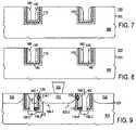
- FIG. 6depicts processing subsequent to FIG. 5 in which portions of the charge storage stack are removed
- FIG. 7depicts processing subsequent to FIG. 6 in which conductive spacers are formed on the trench sidewalls adjacent to the charge storage stack;
- FIG. 8depicts processing subsequent to FIG. 7 portions of the charge storage stack not covered by the spacers are removed
- FIG. 9depicts processing subsequent to FIG. 8 in which diffusion regions are formed in exposed portions of the substrate
- FIG. 10is a top view of an array of the storage devices of FIG. 9 ;
- FIG. 11is a programming table for the hot carrier injection regions of the storage device of FIG. 9 .
- a semiconductor-based storage cell and a corresponding fabrication processemploy a trench etched into a semiconductor substrate, a charge storage layer lining the trench, and a control gate spacer on the trench sidewall adjacent to the charge storage layer. Diffusion regions are located underlying a portion of the trench and adjacent to the trench at an upper surface of the substrate.
- the charge storage layerpreferably includes a set of discontinuous storage elements (DSEs).
- DSEsmay be silicon nanocrystals or silicon nanoclusters, which are small, discreet silicon structures embedded in a dielectric layer and capable of holding a positive or negative charge.
- DSEsare not physically or electrically connected to each other, DSEs are less susceptible to charge loss through pin holes in the dielectric layer than conventional storage elements such as conventional polysilicon floating gate structures.
- the preferred implementation of the storage deviceis capable of storing multiple bits of information using hot carrier injection (HCI) programming.
- FIG. 1 through FIG. 9depict a set of partial cross sectional views of a semiconductor wafer at various stages in one embodiment of a process for fabricating a nonvolatile storage device 100 .
- a dielectric liner 104 and a hard mask 106are formed on an upper surface of a semiconductor substrate 102 of a semiconductor wafer 101 .
- Semiconductor substrateis preferably doped or undoped monocrystalline silicon.
- semiconductor substrate 102may include other semiconductors such as germanium or various semiconductor alloys such as the III-V semiconductor alloys including gallium arsenide.
- substrate 102is a semiconductor on insulator (SOI) substrate.
- SOIsemiconductor on insulator
- dielectric liner 104is silicon oxide, which may be thermally formed (grown) or deposited using CVD (chemical vapor deposition).
- Hard mask 106is preferably a dielectric that can be selectively etched with respect to substrate 102 .
- Hard mask 106is preferably CVD silicon nitride, which is desirable for its ability to inhibit oxidation of an underlying semiconductor thereby providing a mask for a thermal oxidation process.
- trenches 108are formed in semiconductor substrate 102 .
- Trenches 108define the basic structure of the storage device to be formed. Formation of trenches 108 includes conventional photolithographic patterning of dielectric liner 104 and hard mask 106 , followed by a dry etch process that etches the semiconductor material (e.g., silicon) preferentially with respect to liner 104 and hard mask 106 . Etch processes of this type are well known in the field of semiconductor fabrication. In the depicted implementation, trenches 108 have an aspect of approximately 1:2. A depth of trenches 108 is an implementation detail, but trenches having a depth in the range of approximately 50 nm to 300 nm are desirable for applications requiring a dense storage array.
- a first step in the formation of a charge storage stackincludes the formation of a dielectric, referred to herein as bottom dielectric 110 , on the sidewalls and floor of trenches 108 .
- Bottom dielectric 110is preferably a thin (e.g., 1 nm to 10 nm) high quality dielectric that is employed in the programming and erasing of DSEs that will be formed subsequently.
- a thin dielectricmay be advantageously used to achieve adequate programming times using either injection-based or tunneling-based programming techniques.
- a high quality dielectricmay be advantageously used to withstand the potentially large programming voltages and currents and the potentially large number of programming cycles without exhibiting breakdown or significant leakage.
- bottom dielectric 110is a thermally formed silicon dioxide film having a thickness in the range of approximately 4 to 10 nm.
- thermal oxidation of the trench wallsdoes not substantially increase the thickness of dielectric liner 104 even for embodiment in which dielectric liner 104 is a silicon oxide.
- Dielectric liner 104may include multiple layers of different films.
- a charge storage layer 121has been non-selectively formed on bottom oxide 110 and an upper surface of hard mask 106 .
- Charge storage layer 121represents the structure in or on which charge will be stored to program the bit or bits of storage device 100 .
- charge storage layer 121includes a plurality of DSEs 120 .
- DSEs 120implemented in FIG. 4 as nanocrystals, are a set of discreet accumulations of a material capable of storing a charge. Suitable materials include silicon, polysilicon, various metals, and dielectrics such as silicon nitride, silicon oxynitride, and metal nitrides such as tungsten nitride.
- DSEs 120are silicon DSEs (silicon nanocrystals).
- DSEs 120may be formed in any one of a variety of ways, preferably without requiring any photolithography steps.
- One well-known DSE formation techniqueis to deposit an amorphous silicon layer and heat it to form the nanocrystals.
- Another techniqueis to deposit the nanocrystals using chemical vapor deposition (CVD).
- DSEsmay have various shapes, including hemispherical and spherical, depending upon the deposition technique employed.
- DSEs 120are approximately 10 nm in diameter and are spaced at a predominantly uniform spacing of approximately 10 nm. Regardless of the formation technique used, each DSE 120 is a particle of silicon that is electrically and physically isolated from its neighbors. Alternative materials, including dielectric materials such as silicon nitride may also be used for DSEs.
- top dielectric 130has been non-selectively formed overlying charge storage layer 121 to complete the formation of charge storage stack 131 , which includes bottom dielectric 110 , charge storage layer 121 ( FIG. 4 ), and top dielectric 130 .
- top dielectric 130is a high temperature oxide (HTO) desirable because it exhibits characteristics (e.g., density and dielectric strength) substantially equivalent to thermally formed silicon dioxide.
- the HTOmay be formed by a conventional HTO process such as reacting dichlorosilane and nitrous oxide at temperatures approaching 900° C.
- top dielectric 130is preferably in the range of approximately 5 to 10 nm. Top dielectric 130 may include multiple layers of different materials.
- portions of the charge storage stack 131are selectively removed from the upper surface of substrate 102 so that the charge storage stack 131 remains on the floor and sidewalls of trench 108 .
- selective removal of the charge storage stack 131includes a polish process, an etchback, or a combination thereof.
- the implementation depicted in FIG. 6removes the DSEs 120 and top dielectric 130 .
- retaining the hard mask 106facilitates an embodiment of the processing depicted in FIG. 6 that uses a CMP process by providing a suitable polish stop layer for the CMP.
- electrically conductive control gates spacers 140are formed on sidewalls of trenches 108 adjacent to the charge storage stack 131 . Following formation of the spacers 140 , the remaining portions of hard mask 106 are removed. As depicted in FIG. 7 , spacers 140 are located on top of the portion of the charge storage stack 131 covering the floor of trench 108 as well as adjacent to the portion of charge storage stack 131 that lines the trench sidewalls. In the depicted embodiment, the width of spacers 140 is controlled so that a gap 145 exists between the spacers exposing a portion of charge storage stack 131 on the trench floor.
- control gate spacers 140are formed by conventional CVD of a conformal polysilicon layer followed by an anisotropic polysilicon etch processing according to well known spacer formation techniques.
- control gate spacers 140are of a metal material (e.g., titanium) or another suitable conductive material.
- FIG. 8depicts processing subsequent to FIG. 7 in which portions of charge storage stack 131 within gap 145 are removed.
- the entire charge storage stack 131is removed in the gap 145 between spacers 140 to expose a portion of substrate 102 in the vicinity of gap 145 .
- at least some of gate stack 131is left intact.
- all or some of bottom dielectric 110is left intact while the DSEs 120 and top dielectric 130 are removed. This latter embodiment beneficially preserves a thin dielectric on the substrate 102 within the gap 145 in preparation for a subsequent implantation step.
- the use of a pad oxide in connection with an ion implantationis well known.
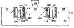
- diffusion regions 152 , 150 - 1 and 150 - 2are formed, preferably simultaneously, where diffusion regions 150 underlie gaps 145 between control gate spacers 140 while diffusion regions 152 occupy an upper portion of substrate 102 between adjacent trenches 108 in substrate 102 .
- Diffusion regions 150 and 152are of the same conductivity type (e.g., n-type for NMOS embodiments), which is opposite the conductivity type of substrate 102 (e.g., p-type for NMOS embodiments).
- diffusion regions 150 and 152are formed using an ion implantation process with a conventional source/drain implant (e.g., phosphorous or arsenic for NMOS or boron for PMOS). Following implantation, a diffusion step is performed by exposing the wafer to an elevated temperature for a specified duration.
- FIG. 9further depicts the formation of a contact 165 to diffusion region 152 between adjacent trenches.
- the gap defined by the control gate spacers 140is shown in FIG. 9 as being completely filled with a polished plug structure 167 .
- plug structure 167is a dielectric that insulates control gates 140 and diffusion regions 150 within the array.
- plug 167includes a dielectric lining and a conductive center to enable a “local” contact to diffusion region 150 .
- diffusion regions 150 and 152as suitable source/drain regions for a storage device 100 having a control gate 140 and an L-shaped transistor channel 103 including a first portion oriented perpendicular to the substrate upper surface and a second portion oriented parallel to the substrate upper surface.
- the effective electrical length of a storage device 100is determined by the trench etch process rather than by one or more photolithography steps. Two instances of storage device 100 are indicated in FIG. 9 by reference numerals 100 - 1 and 100 - 2 .
- Storage device 100 as depicted in FIG. 9thus includes a control gate spacer 140 formed on and adjacent to portions of a charge storage stack 131 including a layer of DSEs 120 lining the sidewalls and floor of a trench 108 formed in substrate 102 .
- a gap 145exists between control gate spacers 140 formed on opposing sidewalls of a trench 108 and diffusion regions 150 in substrate 102 underlie the gaps 145 .
- Diffusion regions 152occupy an upper portion of substrate 102 between adjacent trenches 108 .
- storage device 100is a programmable storage cell transistor in which diffusion regions 150 and 152 serve as the transistor source/drain regions located at opposite ends of L-shaped channel 103 .
- the DSEs 120 in storage stack 131include a first programmable injection region 114 - 1 proximal to diffusion region 152 and a second, independently programmable, injection region 114 - 2 proximal to diffusion region 150 - 1 .
- Each injection region 114encompasses a corresponding portion of DSEs 120 . More specifically, each injection region 114 represents a region of DSEs 120 on which charge is stored to program a corresponding bit of information.
- Storage device 100 - 2 as shown in FIG. 9includes analogous injection regions 114 - 3 and 114 - 4 .
- FIG. 10a top view of the storage device 100 depicted in FIG. 9 emphasizes storage device 100 as part of an array 201 of storage cells 200 .
- storage cell 200includes a pair of storage devices 100 - 1 and 100 - 2 (as well as others not shown), each of which includes a pair of programmable injection regions 114 .
- control gate spacers 140 and the diffusion regions 150extend in parallel fashion across array 201 .
- Diffusion regions 150are electrically continuous structures that run below the substrate lower surface. In one approach, there are no contacts to diffusion regions 150 within a storage cell 200 . Instead, diffusion regions 150 are contacts outside of or at the periphery of storage array 201 . In this approach, the width of diffusion region 150 may “flare” out at the array periphery to provide sufficient space for a contact. If adjacent source/drain regions 150 are close together, this flaring of the source/drain regions may require staggering the flared portion at the periphery.
- array 201includes a metalization interconnect (not depicted) running perpendicular to interconnects 170 , that makes “local” contact (not depicted) to the underlying diffusion region 150 in each “row” of array 201 .
- the local contact embodimentusing multiple contacts to a diffusion region, while decreasing density, provides potentially improved performance through reduced contact resistance.
- Interconnects 170 - 1 and 170 - 2contact diffusion regions 152 through contacts 165 .
- FIG. 10emphasizes cell-to-cell defined by striped mask 163 .
- Striped mask 163in conjunction with appropriate implantation steps, creates junction isolation within array 201 by alternating the conductivity type adjacent rows in array 201 .
- the portions of substrate 102 not covered by interconnects 170provide isolation between adjacent diffusion regions 152 .
- the isolationmay be provided by a conventional dielectric isolation or by silicon of an opposite polarity to diffusion region 152 . Isolation between adjacent diffusion regions 152 is desirable to reduce “disturb” effects when programming a first storage device causes a change in the state of another storage device.
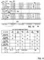
- Storage device 100includes a pair of injection regions 114 - 1 and 114 - 2 programmable using hot carrier injection (HCI) programming.
- Programming table 161 of FIG. 11indicates biasing conditions for programming HCI injection regions 114 - 1 through 114 - 4 .
- the programming conditions listedare for NMOS embodiments of storage device 100 . Opposite polarities apply for PMOS embodiments.
- Programming a first bit of storage device 100 - 1 by injecting electrons into HCI injection region 114 - 1includes biasing diffusion region 152 to a first programming voltage (V P1 ), biasing control gate 140 - 1 to a second programming voltage (V P2 ), and biasing diffusion region 150 - 1 and substrate 102 (also called “WELL 102 ” in FIG. 11 ) to a fourth programming voltage (V P4 ).
- V P1 and V P2are both in the range of approximately 5 V to 9 V while V P4 is 0 V (ground).
- Programming a second bit of storage device 100 - 1 by injecting electrons into HCI injection region 114 - 2includes biasing diffusion region 150 - 1 to V P1 , biasing control gate 140 - 1 to V P2 , and biasing diffusion region 152 and substrate 102 to V P4 .
- Programming a first bit of storage device 100 - 2 by injecting electrons into HCI injection region 114 - 3includes biasing diffusion region 152 to V P1 , biasing control gate 140 - 2 to V P2 , and biasing diffusion region 150 - 2 and substrate 102 to V P4 .
- Programming a second bit of storage device 100 - 2 by injecting electrons into HCI injection region 114 - 4includes biasing diffusion region 150 - 2 to V P1 , biasing control gate 140 - 2 to V P2 , and biasing diffusion region 152 and substrate 102 to V P4 .
- Exemplary programming voltage valuesare included in table 161 . These voltages are preferably applied to storage device 100 for a specified duration, which is preferably on the order of microseconds.
Landscapes
- Engineering & Computer Science (AREA)
- Chemical & Material Sciences (AREA)
- Nanotechnology (AREA)
- Physics & Mathematics (AREA)
- Mathematical Physics (AREA)
- Theoretical Computer Science (AREA)
- Crystallography & Structural Chemistry (AREA)
- Non-Volatile Memory (AREA)
- Semiconductor Memories (AREA)
Abstract
Description
Claims (20)
Priority Applications (1)
| Application Number | Priority Date | Filing Date | Title |
|---|---|---|---|
| US11/525,747US7459744B2 (en) | 2005-07-25 | 2006-09-22 | Hot carrier injection programmable structure including discontinuous storage elements and spacer control gates in a trench and a method of using the same |
Applications Claiming Priority (2)
| Application Number | Priority Date | Filing Date | Title |
|---|---|---|---|
| US11/188,604US7112490B1 (en) | 2005-07-25 | 2005-07-25 | Hot carrier injection programmable structure including discontinuous storage elements and spacer control gates in a trench |
| US11/525,747US7459744B2 (en) | 2005-07-25 | 2006-09-22 | Hot carrier injection programmable structure including discontinuous storage elements and spacer control gates in a trench and a method of using the same |
Related Parent Applications (1)
| Application Number | Title | Priority Date | Filing Date |
|---|---|---|---|
| US11/188,604DivisionUS7112490B1 (en) | 2005-07-25 | 2005-07-25 | Hot carrier injection programmable structure including discontinuous storage elements and spacer control gates in a trench |
Publications (2)
| Publication Number | Publication Date |
|---|---|
| US20070020851A1 US20070020851A1 (en) | 2007-01-25 |
| US7459744B2true US7459744B2 (en) | 2008-12-02 |
Family
ID=37018871
Family Applications (2)
| Application Number | Title | Priority Date | Filing Date |
|---|---|---|---|
| US11/188,604Expired - Fee RelatedUS7112490B1 (en) | 2005-07-25 | 2005-07-25 | Hot carrier injection programmable structure including discontinuous storage elements and spacer control gates in a trench |
| US11/525,747Expired - Fee RelatedUS7459744B2 (en) | 2005-07-25 | 2006-09-22 | Hot carrier injection programmable structure including discontinuous storage elements and spacer control gates in a trench and a method of using the same |
Family Applications Before (1)
| Application Number | Title | Priority Date | Filing Date |
|---|---|---|---|
| US11/188,604Expired - Fee RelatedUS7112490B1 (en) | 2005-07-25 | 2005-07-25 | Hot carrier injection programmable structure including discontinuous storage elements and spacer control gates in a trench |
Country Status (1)
| Country | Link |
|---|---|
| US (2) | US7112490B1 (en) |
Cited By (2)
| Publication number | Priority date | Publication date | Assignee | Title |
|---|---|---|---|---|
| US20120132966A1 (en)* | 2007-10-15 | 2012-05-31 | International Business Machines Corporation | Semiconductor structures having improved contact resistance |
| US8193572B2 (en) | 2007-01-24 | 2012-06-05 | Freescale Semiconductor, Inc. | Electronic device including trenches and discontinuous storage elements |
Families Citing this family (27)
| Publication number | Priority date | Publication date | Assignee | Title |
|---|---|---|---|---|
| US7112490B1 (en)* | 2005-07-25 | 2006-09-26 | Freescale Semiconductor, Inc. | Hot carrier injection programmable structure including discontinuous storage elements and spacer control gates in a trench |
| US7582929B2 (en) | 2005-07-25 | 2009-09-01 | Freescale Semiconductor, Inc | Electronic device including discontinuous storage elements |
| US7619275B2 (en) | 2005-07-25 | 2009-11-17 | Freescale Semiconductor, Inc. | Process for forming an electronic device including discontinuous storage elements |
| US7394686B2 (en)* | 2005-07-25 | 2008-07-01 | Freescale Semiconductor, Inc. | Programmable structure including discontinuous storage elements and spacer control gates in a trench |
| US7642594B2 (en)* | 2005-07-25 | 2010-01-05 | Freescale Semiconductor, Inc | Electronic device including gate lines, bit lines, or a combination thereof |
| US7619270B2 (en)* | 2005-07-25 | 2009-11-17 | Freescale Semiconductor, Inc. | Electronic device including discontinuous storage elements |
| US7262997B2 (en)* | 2005-07-25 | 2007-08-28 | Freescale Semiconductor, Inc. | Process for operating an electronic device including a memory array and conductive lines |
| US7211858B2 (en)* | 2005-07-25 | 2007-05-01 | Freescale Semiconductor, Inc. | Split gate storage device including a horizontal first gate and a vertical second gate in a trench |
| TWI285414B (en)* | 2005-10-21 | 2007-08-11 | Powerchip Semiconductor Corp | Non-volatile memory and manufacturing method and operating method thereof |
| US7592224B2 (en) | 2006-03-30 | 2009-09-22 | Freescale Semiconductor, Inc | Method of fabricating a storage device including decontinuous storage elements within and between trenches |
| US7667260B2 (en)* | 2006-08-09 | 2010-02-23 | Micron Technology, Inc. | Nanoscale floating gate and methods of formation |
| US7572699B2 (en)* | 2007-01-24 | 2009-08-11 | Freescale Semiconductor, Inc | Process of forming an electronic device including fins and discontinuous storage elements |
| US7838922B2 (en) | 2007-01-24 | 2010-11-23 | Freescale Semiconductor, Inc. | Electronic device including trenches and discontinuous storage elements |
| US8803217B2 (en)* | 2007-03-13 | 2014-08-12 | Freescale Semiconductor, Inc. | Process of forming an electronic device including a control gate electrode, a semiconductor layer, and a select gate electrode |
| US7692972B1 (en) | 2008-07-22 | 2010-04-06 | Actel Corporation | Split gate memory cell for programmable circuit device |
| US8525263B2 (en) | 2009-01-19 | 2013-09-03 | International Business Machines Corporation | Programmable high-k/metal gate memory device |
| US8384145B2 (en)* | 2009-02-03 | 2013-02-26 | International Business Machines Corporation | Non-volatile memory device using hot-carrier injection |
| DE102009010579A1 (en) | 2009-02-25 | 2010-08-26 | ETH Zürich | System and method for remote monitoring of objects |
| US8077512B2 (en)* | 2009-08-18 | 2011-12-13 | Nanya Technology Corp. | Flash memory cell and method for operating the same |
| US8951892B2 (en) | 2012-06-29 | 2015-02-10 | Freescale Semiconductor, Inc. | Applications for nanopillar structures |
| US8853027B2 (en) | 2012-10-01 | 2014-10-07 | Freescale Semiconductor, Inc. | Split gate flash cell |
| US9178077B2 (en) | 2012-11-13 | 2015-11-03 | Micron Technology, Inc. | Semiconductor constructions |
| US9105737B2 (en) | 2013-01-07 | 2015-08-11 | Micron Technology, Inc. | Semiconductor constructions |
| US8853769B2 (en) | 2013-01-10 | 2014-10-07 | Micron Technology, Inc. | Transistors and semiconductor constructions |
| US9219070B2 (en) | 2013-02-05 | 2015-12-22 | Micron Technology, Inc. | 3-D memory arrays |
| US9159845B2 (en)* | 2013-05-15 | 2015-10-13 | Micron Technology, Inc. | Charge-retaining transistor, array of memory cells, and methods of forming a charge-retaining transistor |
| US9356106B2 (en)* | 2014-09-04 | 2016-05-31 | Freescale Semiconductor, Inc. | Method to form self-aligned high density nanocrystals |
Citations (88)
| Publication number | Priority date | Publication date | Assignee | Title |
|---|---|---|---|---|
| US4184207A (en) | 1978-01-27 | 1980-01-15 | Texas Instruments Incorporated | High density floating gate electrically programmable ROM |
| US4751558A (en) | 1985-10-31 | 1988-06-14 | International Business Machines Corporation | High density memory with field shield |
| US4785337A (en) | 1986-10-17 | 1988-11-15 | International Business Machines Corporation | Dynamic ram cell having shared trench storage capacitor with sidewall-defined bridge contacts and gate electrodes |
| US4833094A (en) | 1986-10-17 | 1989-05-23 | International Business Machines Corporation | Method of making a dynamic ram cell having shared trench storage capacitor with sidewall-defined bridge contacts and gate electrodes |
| US4860070A (en) | 1987-01-09 | 1989-08-22 | Mitsubishi Denki Kabushiki Kaisha | Semiconductor memory device comprising trench memory cells |
| US5196722A (en) | 1992-03-12 | 1993-03-23 | International Business Machines Corporation | Shadow ram cell having a shallow trench eeprom |
| US5252845A (en) | 1990-04-02 | 1993-10-12 | Electronics And Telecommunications Research Institute | Trench DRAM cell with vertical transistor |
| US5315142A (en) | 1992-03-23 | 1994-05-24 | International Business Machines Corporation | High performance trench EEPROM cell |
| US5411905A (en) | 1994-04-29 | 1995-05-02 | International Business Machines Corporation | Method of making trench EEPROM structure on SOI with dual channels |
| US5432365A (en) | 1988-02-15 | 1995-07-11 | Samsung Electronics Co., Ltd. | Semiconductor memory device |
| US5460988A (en) | 1994-04-25 | 1995-10-24 | United Microelectronics Corporation | Process for high density flash EPROM cell |
| US5705415A (en) | 1994-10-04 | 1998-01-06 | Motorola, Inc. | Process for forming an electrically programmable read-only memory cell |
| US5721448A (en) | 1996-07-30 | 1998-02-24 | International Business Machines Corporation | Integrated circuit chip having isolation trenches composed of a dielectric layer with oxidation catalyst material |
| US5786612A (en) | 1995-10-25 | 1998-07-28 | Mitsubishi Denki Kabushiki Kaisha | Semiconductor device comprising trench EEPROM |
| US5801415A (en) | 1996-05-16 | 1998-09-01 | Taiwan Semiconductor Manufacturing Company Ltd. | Non-volatile-memory cell for electrically programmable read only memory having a trench-like coupling capacitors |
| US5824580A (en) | 1996-07-30 | 1998-10-20 | International Business Machines Corporation | Method of manufacturing an insulated gate field effect transistor |
| US5907775A (en) | 1997-04-11 | 1999-05-25 | Vanguard International Semiconductor Corporation | Non-volatile memory device with high gate coupling ratio and manufacturing process therefor |
| US5914523A (en) | 1998-02-17 | 1999-06-22 | National Semiconductor Corp. | Semiconductor device trench isolation structure with polysilicon bias voltage contact |
| US5923046A (en) | 1996-09-13 | 1999-07-13 | Kabushiki Kaisha Toshiba | Quantum dot memory cell |
| US5969383A (en) | 1997-06-16 | 1999-10-19 | Motorola, Inc. | Split-gate memory device and method for accessing the same |
| US5998263A (en) | 1996-05-16 | 1999-12-07 | Altera Corporation | High-density nonvolatile memory cell |
| US6074954A (en) | 1998-08-31 | 2000-06-13 | Applied Materials, Inc | Process for control of the shape of the etch front in the etching of polysilicon |
| US6117733A (en) | 1998-05-27 | 2000-09-12 | Taiwan Semiconductor Manufacturing Company | Poly tip formation and self-align source process for split-gate flash cell |
| US6133601A (en) | 1996-12-11 | 2000-10-17 | Kabushiki Kaisha Toshiba | Non-volatile semiconductor memory device with inter-layer insulation film |
| US6172905B1 (en) | 2000-02-01 | 2001-01-09 | Motorola, Inc. | Method of operating a semiconductor device |
| US6228706B1 (en) | 1999-08-26 | 2001-05-08 | International Business Machines Corporation | Vertical DRAM cell with TFT over trench capacitor |
| US6265268B1 (en) | 1999-10-25 | 2001-07-24 | Advanced Micro Devices, Inc. | High temperature oxide deposition process for fabricating an ONO floating-gate electrode in a two bit EEPROM device |
| US6281064B1 (en) | 1999-06-04 | 2001-08-28 | International Business Machines Corporation | Method for providing dual work function doping and protective insulating cap |
| US6287917B1 (en) | 1999-09-08 | 2001-09-11 | Advanced Micro Devices, Inc. | Process for fabricating an MNOS flash memory device |
| US6307782B1 (en) | 2000-04-03 | 2001-10-23 | Motorola, Inc. | Process for operating a semiconductor device |
| US6320784B1 (en) | 2000-03-14 | 2001-11-20 | Motorola, Inc. | Memory cell and method for programming thereof |
| US6365452B1 (en) | 1998-03-19 | 2002-04-02 | Lsi Logic Corporation | DRAM cell having a vertical transistor and a capacitor formed on the sidewalls of a trench isolation |
| US6368916B1 (en) | 1999-10-22 | 2002-04-09 | Fujitsu Limited | Method for fabricating nonvolatile semiconductor memory device |
| US6373096B1 (en) | 1999-01-22 | 2002-04-16 | Nec Corporation | Method of manufacturing semiconductor device, nonvolatile semiconductor memory device and method of manufacturing the same |
| US6372617B1 (en) | 1997-12-17 | 2002-04-16 | Nec Corporation | Method of manufacturing non-volatile memory |
| US6399441B1 (en) | 1999-08-05 | 2002-06-04 | Halo Lsi Device & Design Technology, Inc. | Nonvolatile memory cell, method of programming the same and nonvolatile memory array |
| US6461905B1 (en) | 2002-02-22 | 2002-10-08 | Advanced Micro Devices, Inc. | Dummy gate process to reduce the Vss resistance of flash products |
| US20020151136A1 (en) | 1998-03-05 | 2002-10-17 | Taiwan Semiconductor Manufacturing Company | Method of manufacture of vertical split gate flash memory device and device manufactured thereby |
| US6486028B1 (en) | 2001-11-20 | 2002-11-26 | Macronix International Co., Ltd. | Method of fabricating a nitride read-only-memory cell vertical structure |
| US6537870B1 (en) | 2000-09-29 | 2003-03-25 | Infineon Technologies Ag | Method of forming an integrated circuit comprising a self aligned trench |
| US6544827B2 (en) | 1998-08-24 | 2003-04-08 | Nec Corporation | Metal-gate field effect transistor and method for manufacturing the same |
| US20030068864A1 (en) | 2001-10-10 | 2003-04-10 | Park Il-Yong | Method for fabricating power semiconductor device having trench gate structure |
| US6555427B1 (en) | 1999-08-31 | 2003-04-29 | Kabushiki Kaisha Toshiba | Non-volatile semiconductor memory device and manufacturing method thereof |
| US6559032B2 (en) | 1996-01-05 | 2003-05-06 | Micron Technology, Inc. | Method of fabricating an isolation structure on a semiconductor substrate |
| US6620664B2 (en) | 2002-02-07 | 2003-09-16 | Sharp Laboratories Of America, Inc. | Silicon-germanium MOSFET with deposited gate dielectric and metal gate electrode and method for making the same |
| US6638810B2 (en) | 2000-02-22 | 2003-10-28 | Applied Materials, Inc. | Tantalum nitride CVD deposition by tantalum oxide densification |
| US20040000688A1 (en) | 2001-05-18 | 2004-01-01 | Sandisk Corporation | Non-volatile memory cells utilizing substrate trenches |
| US6674120B2 (en) | 2000-05-02 | 2004-01-06 | Sony Corporation | Nonvolatile semiconductor memory device and method of operation thereof |
| US6673681B2 (en) | 1999-05-19 | 2004-01-06 | Fairchild Semiconductor Corporation | Process for forming MOS-gated power device having segmented trench and extended doping zone |
| US6677204B2 (en) | 2000-08-14 | 2004-01-13 | Matrix Semiconductor, Inc. | Multigate semiconductor device with vertical channel current and method of fabrication |
| US6687156B2 (en) | 1999-07-14 | 2004-02-03 | Hitachi, Ltd. | Semiconductor integrated circuit device, production and operation method thereof |
| US6706599B1 (en) | 2003-03-20 | 2004-03-16 | Motorola, Inc. | Multi-bit non-volatile memory device and method therefor |
| US6709922B2 (en) | 2001-01-30 | 2004-03-23 | Seiko Epson Corporation | Method of manufacturing semiconductor integrated circuit device including nonvolatile semiconductor memory devices |
| US6713834B2 (en) | 2000-10-30 | 2004-03-30 | Kabushiki Kaisha Toshiba | Semiconductor device having two-layered charge storage electrode |
| US6734492B2 (en) | 1996-01-22 | 2004-05-11 | Semiconductor Energy Laboratory Co., Ltd. | Nonvolatile vertical channel semiconductor device |
| US6747308B2 (en) | 2001-12-28 | 2004-06-08 | Texas Instruments Incorporated | Single poly EEPROM with reduced area |
| US6750499B2 (en) | 2002-08-06 | 2004-06-15 | Intelligent Sources Development Corp. | Self-aligned trench-type dram structure and its contactless dram arrays |
| US6762092B2 (en) | 2001-08-08 | 2004-07-13 | Sandisk Corporation | Scalable self-aligned dual floating gate memory cell array and methods of forming the array |
| US6803620B2 (en) | 2000-10-27 | 2004-10-12 | Sony Corporation | Non-volatile semiconductor memory device and a method of producing the same |
| US6816414B1 (en) | 2003-07-31 | 2004-11-09 | Freescale Semiconductor, Inc. | Nonvolatile memory and method of making same |
| US6818512B1 (en) | 2002-01-04 | 2004-11-16 | Taiwan Semiconductor Manufacturing Company | Split-gate flash with source/drain multi-sharing |
| US6818939B1 (en) | 2003-07-18 | 2004-11-16 | Semiconductor Components Industries, L.L.C. | Vertical compound semiconductor field effect transistor structure |
| US20040248371A1 (en) | 2003-06-06 | 2004-12-09 | Chih-Hsin Wang | Floating-gate memory cell having trench structure with ballastic-charge injector and array of memory cells |
| US6853587B2 (en) | 2002-06-21 | 2005-02-08 | Micron Technology, Inc. | Vertical NROM having a storage density of 1 bit per 1F2 |
| US20050037576A1 (en) | 2003-08-14 | 2005-02-17 | Bomy Chen | Method of manufacturing an array of bi-directional nonvolatile memory cells |
| US6864540B1 (en) | 2004-05-21 | 2005-03-08 | International Business Machines Corp. | High performance FET with elevated source/drain region |
| US6894339B2 (en) | 2003-01-02 | 2005-05-17 | Actrans System Inc. | Flash memory with trench select gate and fabrication process |
| US6903418B2 (en) | 2001-02-09 | 2005-06-07 | Fuji Electric Device Technology Co., Ltd. | Semiconductor device |
| US20050148173A1 (en) | 2004-01-05 | 2005-07-07 | Fuja Shone | Non-volatile memory array having vertical transistors and manufacturing method thereof |
| US20050146938A1 (en)* | 1997-01-29 | 2005-07-07 | Micron Technology, Inc. | Transistor with nanocrystalline silicon gate structure |
| US6916715B2 (en) | 2002-11-18 | 2005-07-12 | Nanya Technology Corporation | Method for fabricating a vertical NROM cell |
| US6952034B2 (en)* | 2002-04-05 | 2005-10-04 | Silicon Storage Technology, Inc. | Semiconductor memory array of floating gate memory cells with buried source line and floating gate |
| US20050242391A1 (en) | 2004-05-03 | 2005-11-03 | The Regents Of The University Of California | Two bit/four bit SONOS flash memory cell |
| US20050280094A1 (en) | 2003-11-17 | 2005-12-22 | Micron Technology, Inc. | NROM flash memory devices on ultrathin silicon |
| US20060011966A1 (en) | 2004-07-15 | 2006-01-19 | Promos Technologies Inc. | Structure of a non-volatile memory cell and method of forming the same |
| US6998313B2 (en) | 2002-12-17 | 2006-02-14 | Nanya Technology Corporation | Stacked gate flash memory device and method of fabricating the same |
| US20060046383A1 (en) | 2004-09-02 | 2006-03-02 | Shenlin Chen | Method for forming a nanocrystal floating gate for a flash memory device |
| US7015537B2 (en) | 2004-04-12 | 2006-03-21 | Silicon Storage Technology, Inc. | Isolation-less, contact-less array of nonvolatile memory cells each having a floating gate for storage of charges, and methods of manufacturing, and operating therefor |
| US7045423B2 (en) | 2001-05-28 | 2006-05-16 | Kabushiki Kaisha Toshiba | Non-volatile semiconductor memory device with multi-layer gate structure |
| US20060131640A1 (en) | 2004-03-16 | 2006-06-22 | Andy Yu | Memory array of non-volatile electrically alterable memory cells for storing multiple data |
| US20060152978A1 (en) | 2003-12-16 | 2006-07-13 | Micron Technology, Inc. | Multi-state NROM device |
| US7078286B1 (en) | 2002-09-06 | 2006-07-18 | Lattice Semiconductor Corporation | Process for fabricating a semiconductor device having electrically isolated low voltage and high voltage regions |
| US7098502B2 (en) | 2003-11-10 | 2006-08-29 | Freescale Semiconductor, Inc. | Transistor having three electrically isolated electrodes and method of formation |
| US7112490B1 (en) | 2005-07-25 | 2006-09-26 | Freescale Semiconductor, Inc. | Hot carrier injection programmable structure including discontinuous storage elements and spacer control gates in a trench |
| US7196935B2 (en) | 2004-05-18 | 2007-03-27 | Micron Technolnology, Inc. | Ballistic injection NROM flash memory |
| US7199419B2 (en) | 2004-12-13 | 2007-04-03 | Micron Technology, Inc. | Memory structure for reduced floating body effect |
| US7220634B2 (en) | 2002-06-21 | 2007-05-22 | Micron Technology, Inc. | NROM memory cell, memory array, related devices and methods |
| US7259984B2 (en) | 2002-11-26 | 2007-08-21 | Cornell Research Foundation, Inc. | Multibit metal nanocrystal memories and fabrication |
Family Cites Families (2)
| Publication number | Priority date | Publication date | Assignee | Title |
|---|---|---|---|---|
| US6991984B2 (en)* | 2004-01-27 | 2006-01-31 | Freescale Semiconductor, Inc. | Method for forming a memory structure using a modified surface topography and structure thereof |
| US7126188B2 (en)* | 2004-05-27 | 2006-10-24 | Skymedi Corporation | Vertical split gate memory cell and manufacturing method thereof |
- 2005
- 2005-07-25USUS11/188,604patent/US7112490B1/ennot_activeExpired - Fee Related
- 2006
- 2006-09-22USUS11/525,747patent/US7459744B2/ennot_activeExpired - Fee Related
Patent Citations (98)
| Publication number | Priority date | Publication date | Assignee | Title |
|---|---|---|---|---|
| US4184207A (en) | 1978-01-27 | 1980-01-15 | Texas Instruments Incorporated | High density floating gate electrically programmable ROM |
| US4751558A (en) | 1985-10-31 | 1988-06-14 | International Business Machines Corporation | High density memory with field shield |
| US4785337A (en) | 1986-10-17 | 1988-11-15 | International Business Machines Corporation | Dynamic ram cell having shared trench storage capacitor with sidewall-defined bridge contacts and gate electrodes |
| US4833094A (en) | 1986-10-17 | 1989-05-23 | International Business Machines Corporation | Method of making a dynamic ram cell having shared trench storage capacitor with sidewall-defined bridge contacts and gate electrodes |
| US4860070A (en) | 1987-01-09 | 1989-08-22 | Mitsubishi Denki Kabushiki Kaisha | Semiconductor memory device comprising trench memory cells |
| US5432365A (en) | 1988-02-15 | 1995-07-11 | Samsung Electronics Co., Ltd. | Semiconductor memory device |
| US5252845A (en) | 1990-04-02 | 1993-10-12 | Electronics And Telecommunications Research Institute | Trench DRAM cell with vertical transistor |
| US5196722A (en) | 1992-03-12 | 1993-03-23 | International Business Machines Corporation | Shadow ram cell having a shallow trench eeprom |
| US5315142A (en) | 1992-03-23 | 1994-05-24 | International Business Machines Corporation | High performance trench EEPROM cell |
| US5567635A (en) | 1992-03-23 | 1996-10-22 | International Business Machines Corporation | Method of making a three dimensional trench EEPROM cell structure |
| US5460988A (en) | 1994-04-25 | 1995-10-24 | United Microelectronics Corporation | Process for high density flash EPROM cell |
| US5411905A (en) | 1994-04-29 | 1995-05-02 | International Business Machines Corporation | Method of making trench EEPROM structure on SOI with dual channels |
| US5705415A (en) | 1994-10-04 | 1998-01-06 | Motorola, Inc. | Process for forming an electrically programmable read-only memory cell |
| US5786612A (en) | 1995-10-25 | 1998-07-28 | Mitsubishi Denki Kabushiki Kaisha | Semiconductor device comprising trench EEPROM |
| US6559032B2 (en) | 1996-01-05 | 2003-05-06 | Micron Technology, Inc. | Method of fabricating an isolation structure on a semiconductor substrate |
| US6734492B2 (en) | 1996-01-22 | 2004-05-11 | Semiconductor Energy Laboratory Co., Ltd. | Nonvolatile vertical channel semiconductor device |
| US5801415A (en) | 1996-05-16 | 1998-09-01 | Taiwan Semiconductor Manufacturing Company Ltd. | Non-volatile-memory cell for electrically programmable read only memory having a trench-like coupling capacitors |
| US5998263A (en) | 1996-05-16 | 1999-12-07 | Altera Corporation | High-density nonvolatile memory cell |
| US5824580A (en) | 1996-07-30 | 1998-10-20 | International Business Machines Corporation | Method of manufacturing an insulated gate field effect transistor |
| US5721448A (en) | 1996-07-30 | 1998-02-24 | International Business Machines Corporation | Integrated circuit chip having isolation trenches composed of a dielectric layer with oxidation catalyst material |
| US5923046A (en) | 1996-09-13 | 1999-07-13 | Kabushiki Kaisha Toshiba | Quantum dot memory cell |
| US6133601A (en) | 1996-12-11 | 2000-10-17 | Kabushiki Kaisha Toshiba | Non-volatile semiconductor memory device with inter-layer insulation film |
| US20050146938A1 (en)* | 1997-01-29 | 2005-07-07 | Micron Technology, Inc. | Transistor with nanocrystalline silicon gate structure |
| US5907775A (en) | 1997-04-11 | 1999-05-25 | Vanguard International Semiconductor Corporation | Non-volatile memory device with high gate coupling ratio and manufacturing process therefor |
| US5969383A (en) | 1997-06-16 | 1999-10-19 | Motorola, Inc. | Split-gate memory device and method for accessing the same |
| US6372617B1 (en) | 1997-12-17 | 2002-04-16 | Nec Corporation | Method of manufacturing non-volatile memory |
| US6121148A (en) | 1998-02-17 | 2000-09-19 | National Semiconductor Corporation | Semiconductor device trench isolation structure with polysilicon bias voltage contact |
| US5914523A (en) | 1998-02-17 | 1999-06-22 | National Semiconductor Corp. | Semiconductor device trench isolation structure with polysilicon bias voltage contact |
| US6583466B2 (en) | 1998-03-05 | 2003-06-24 | Taiwan Semiconductor Manufacturing Company | Vertical split gate flash memory device in an orthogonal array of rows and columns with devices in columns having shared source regions |
| US20020151136A1 (en) | 1998-03-05 | 2002-10-17 | Taiwan Semiconductor Manufacturing Company | Method of manufacture of vertical split gate flash memory device and device manufactured thereby |
| US6365452B1 (en) | 1998-03-19 | 2002-04-02 | Lsi Logic Corporation | DRAM cell having a vertical transistor and a capacitor formed on the sidewalls of a trench isolation |
| US6117733A (en) | 1998-05-27 | 2000-09-12 | Taiwan Semiconductor Manufacturing Company | Poly tip formation and self-align source process for split-gate flash cell |
| US6544827B2 (en) | 1998-08-24 | 2003-04-08 | Nec Corporation | Metal-gate field effect transistor and method for manufacturing the same |
| US6074954A (en) | 1998-08-31 | 2000-06-13 | Applied Materials, Inc | Process for control of the shape of the etch front in the etching of polysilicon |
| US6373096B1 (en) | 1999-01-22 | 2002-04-16 | Nec Corporation | Method of manufacturing semiconductor device, nonvolatile semiconductor memory device and method of manufacturing the same |
| US6673681B2 (en) | 1999-05-19 | 2004-01-06 | Fairchild Semiconductor Corporation | Process for forming MOS-gated power device having segmented trench and extended doping zone |
| US6281064B1 (en) | 1999-06-04 | 2001-08-28 | International Business Machines Corporation | Method for providing dual work function doping and protective insulating cap |
| US6687156B2 (en) | 1999-07-14 | 2004-02-03 | Hitachi, Ltd. | Semiconductor integrated circuit device, production and operation method thereof |
| US6399441B1 (en) | 1999-08-05 | 2002-06-04 | Halo Lsi Device & Design Technology, Inc. | Nonvolatile memory cell, method of programming the same and nonvolatile memory array |
| US6228706B1 (en) | 1999-08-26 | 2001-05-08 | International Business Machines Corporation | Vertical DRAM cell with TFT over trench capacitor |
| US6818508B2 (en) | 1999-08-31 | 2004-11-16 | Kabushiki Kaisha Toshiba | Non-volatile semiconductor memory device and manufacturing method thereof |
| US7122432B2 (en) | 1999-08-31 | 2006-10-17 | Kabushiki Kaisha Toshiba | Non-volatile semiconductor memory device and manufacturing method thereof |
| US6555427B1 (en) | 1999-08-31 | 2003-04-29 | Kabushiki Kaisha Toshiba | Non-volatile semiconductor memory device and manufacturing method thereof |
| US6287917B1 (en) | 1999-09-08 | 2001-09-11 | Advanced Micro Devices, Inc. | Process for fabricating an MNOS flash memory device |
| US6368916B1 (en) | 1999-10-22 | 2002-04-09 | Fujitsu Limited | Method for fabricating nonvolatile semiconductor memory device |
| US6265268B1 (en) | 1999-10-25 | 2001-07-24 | Advanced Micro Devices, Inc. | High temperature oxide deposition process for fabricating an ONO floating-gate electrode in a two bit EEPROM device |
| US6330184B1 (en) | 2000-02-01 | 2001-12-11 | Motorola, Inc. | Method of operating a semiconductor device |
| US6172905B1 (en) | 2000-02-01 | 2001-01-09 | Motorola, Inc. | Method of operating a semiconductor device |
| US6638810B2 (en) | 2000-02-22 | 2003-10-28 | Applied Materials, Inc. | Tantalum nitride CVD deposition by tantalum oxide densification |
| US6320784B1 (en) | 2000-03-14 | 2001-11-20 | Motorola, Inc. | Memory cell and method for programming thereof |
| US6307782B1 (en) | 2000-04-03 | 2001-10-23 | Motorola, Inc. | Process for operating a semiconductor device |
| US6674120B2 (en) | 2000-05-02 | 2004-01-06 | Sony Corporation | Nonvolatile semiconductor memory device and method of operation thereof |
| US6677204B2 (en) | 2000-08-14 | 2004-01-13 | Matrix Semiconductor, Inc. | Multigate semiconductor device with vertical channel current and method of fabrication |
| US6537870B1 (en) | 2000-09-29 | 2003-03-25 | Infineon Technologies Ag | Method of forming an integrated circuit comprising a self aligned trench |
| US6803620B2 (en) | 2000-10-27 | 2004-10-12 | Sony Corporation | Non-volatile semiconductor memory device and a method of producing the same |
| US6713834B2 (en) | 2000-10-30 | 2004-03-30 | Kabushiki Kaisha Toshiba | Semiconductor device having two-layered charge storage electrode |
| US6709922B2 (en) | 2001-01-30 | 2004-03-23 | Seiko Epson Corporation | Method of manufacturing semiconductor integrated circuit device including nonvolatile semiconductor memory devices |
| US6903418B2 (en) | 2001-02-09 | 2005-06-07 | Fuji Electric Device Technology Co., Ltd. | Semiconductor device |
| US20040000688A1 (en) | 2001-05-18 | 2004-01-01 | Sandisk Corporation | Non-volatile memory cells utilizing substrate trenches |
| US6936887B2 (en) | 2001-05-18 | 2005-08-30 | Sandisk Corporation | Non-volatile memory cells utilizing substrate trenches |
| US7045423B2 (en) | 2001-05-28 | 2006-05-16 | Kabushiki Kaisha Toshiba | Non-volatile semiconductor memory device with multi-layer gate structure |
| US6762092B2 (en) | 2001-08-08 | 2004-07-13 | Sandisk Corporation | Scalable self-aligned dual floating gate memory cell array and methods of forming the array |
| US20030068864A1 (en) | 2001-10-10 | 2003-04-10 | Park Il-Yong | Method for fabricating power semiconductor device having trench gate structure |
| US6486028B1 (en) | 2001-11-20 | 2002-11-26 | Macronix International Co., Ltd. | Method of fabricating a nitride read-only-memory cell vertical structure |
| US6747308B2 (en) | 2001-12-28 | 2004-06-08 | Texas Instruments Incorporated | Single poly EEPROM with reduced area |
| US6818512B1 (en) | 2002-01-04 | 2004-11-16 | Taiwan Semiconductor Manufacturing Company | Split-gate flash with source/drain multi-sharing |
| US6620664B2 (en) | 2002-02-07 | 2003-09-16 | Sharp Laboratories Of America, Inc. | Silicon-germanium MOSFET with deposited gate dielectric and metal gate electrode and method for making the same |
| US6461905B1 (en) | 2002-02-22 | 2002-10-08 | Advanced Micro Devices, Inc. | Dummy gate process to reduce the Vss resistance of flash products |
| US6952034B2 (en)* | 2002-04-05 | 2005-10-04 | Silicon Storage Technology, Inc. | Semiconductor memory array of floating gate memory cells with buried source line and floating gate |
| US7220634B2 (en) | 2002-06-21 | 2007-05-22 | Micron Technology, Inc. | NROM memory cell, memory array, related devices and methods |
| US6853587B2 (en) | 2002-06-21 | 2005-02-08 | Micron Technology, Inc. | Vertical NROM having a storage density of 1 bit per 1F2 |
| US6750499B2 (en) | 2002-08-06 | 2004-06-15 | Intelligent Sources Development Corp. | Self-aligned trench-type dram structure and its contactless dram arrays |
| US7078286B1 (en) | 2002-09-06 | 2006-07-18 | Lattice Semiconductor Corporation | Process for fabricating a semiconductor device having electrically isolated low voltage and high voltage regions |
| US6916715B2 (en) | 2002-11-18 | 2005-07-12 | Nanya Technology Corporation | Method for fabricating a vertical NROM cell |
| US7259984B2 (en) | 2002-11-26 | 2007-08-21 | Cornell Research Foundation, Inc. | Multibit metal nanocrystal memories and fabrication |
| US6998313B2 (en) | 2002-12-17 | 2006-02-14 | Nanya Technology Corporation | Stacked gate flash memory device and method of fabricating the same |
| US6894339B2 (en) | 2003-01-02 | 2005-05-17 | Actrans System Inc. | Flash memory with trench select gate and fabrication process |
| US6706599B1 (en) | 2003-03-20 | 2004-03-16 | Motorola, Inc. | Multi-bit non-volatile memory device and method therefor |
| US20040248371A1 (en) | 2003-06-06 | 2004-12-09 | Chih-Hsin Wang | Floating-gate memory cell having trench structure with ballastic-charge injector and array of memory cells |
| US6818939B1 (en) | 2003-07-18 | 2004-11-16 | Semiconductor Components Industries, L.L.C. | Vertical compound semiconductor field effect transistor structure |
| US6816414B1 (en) | 2003-07-31 | 2004-11-09 | Freescale Semiconductor, Inc. | Nonvolatile memory and method of making same |
| US20050037576A1 (en) | 2003-08-14 | 2005-02-17 | Bomy Chen | Method of manufacturing an array of bi-directional nonvolatile memory cells |
| US7098502B2 (en) | 2003-11-10 | 2006-08-29 | Freescale Semiconductor, Inc. | Transistor having three electrically isolated electrodes and method of formation |
| US20050280089A1 (en) | 2003-11-17 | 2005-12-22 | Micron Technology, Inc. | NROM flash memory devices on ultrathin silicon |
| US20050280094A1 (en) | 2003-11-17 | 2005-12-22 | Micron Technology, Inc. | NROM flash memory devices on ultrathin silicon |
| US20060152978A1 (en) | 2003-12-16 | 2006-07-13 | Micron Technology, Inc. | Multi-state NROM device |
| US20060166443A1 (en) | 2003-12-16 | 2006-07-27 | Micron Technology, Inc. | Multi-state NROM device |
| US7371642B2 (en) | 2003-12-16 | 2008-05-13 | Micron Technology, Inc. | Multi-state NROM device |
| US20050148173A1 (en) | 2004-01-05 | 2005-07-07 | Fuja Shone | Non-volatile memory array having vertical transistors and manufacturing method thereof |
| US20060131640A1 (en) | 2004-03-16 | 2006-06-22 | Andy Yu | Memory array of non-volatile electrically alterable memory cells for storing multiple data |
| US7015537B2 (en) | 2004-04-12 | 2006-03-21 | Silicon Storage Technology, Inc. | Isolation-less, contact-less array of nonvolatile memory cells each having a floating gate for storage of charges, and methods of manufacturing, and operating therefor |
| US20050242391A1 (en) | 2004-05-03 | 2005-11-03 | The Regents Of The University Of California | Two bit/four bit SONOS flash memory cell |
| US7196935B2 (en) | 2004-05-18 | 2007-03-27 | Micron Technolnology, Inc. | Ballistic injection NROM flash memory |
| US6864540B1 (en) | 2004-05-21 | 2005-03-08 | International Business Machines Corp. | High performance FET with elevated source/drain region |
| US20060011966A1 (en) | 2004-07-15 | 2006-01-19 | Promos Technologies Inc. | Structure of a non-volatile memory cell and method of forming the same |
| US20060046383A1 (en) | 2004-09-02 | 2006-03-02 | Shenlin Chen | Method for forming a nanocrystal floating gate for a flash memory device |
| US7199419B2 (en) | 2004-12-13 | 2007-04-03 | Micron Technology, Inc. | Memory structure for reduced floating body effect |
| US7112490B1 (en) | 2005-07-25 | 2006-09-26 | Freescale Semiconductor, Inc. | Hot carrier injection programmable structure including discontinuous storage elements and spacer control gates in a trench |
Non-Patent Citations (32)
| Title |
|---|
| Actions on the Merits by U.S.P.T.O, as of Apr. 16, 2008, 12 pgs. |
| Actions on the Merits by U.S.P.T.O, as of Jul. 25, 2008, 13 pgs. |
| Actions on the Merits by U.S.P.T.O, as of Jul. 26, 2007, 8 pages. |
| Actions on the Merits by U.S.P.T.O, as of Nov. 8, 2007, 10 pgs. |
| Guan, H., et al. "An Analytical Model for Optimization of Programming Efficiency and Uniformity of Split Gate Source-Side Injection Superflash Memory," IEEE Transactions on Electron Devices, vol. 50, No. 3, pp. 809-815, Mar. 2003. |
| Hayashi, Y., et al. "Twin MONOS Cell with Dual Control Gates," 2000 Symposium on VLSI Technology Digest of Technical Papers, pp. 122-123, 2000. |
| Lee, D., et al. "Vertical Floating-Gate 4.5F2 Split-Gate NOR Flash Memory at 110nm Node," 2004 Symposium on VLSI Technology Digest of Technical Papers, pp. 72-73, 2004. |
| Ma, Y. et al. "A Dual-Bit Split-Gate EEPROM (DSG) Cell in Contactless Array for Single-Vcc High Density Flash Memories," IEDM, p. 57-60, 1994. |
| Osabe, T. et al. "Charge-Injection Length in Silicon Nanocrystal Memory Cells," 2004 Symposium on VLSI Technology Digest of Technical Papers p. 242-243, 2004. |
| U.S. Appl. No. 10/961,295, filed Oct. 8, 2004. |
| U.S. Appl. No. 11/079,674, filed Mar. 14, 2005. |
| U.S. Appl. No. 11/188,582, filed Jul. 25, 2005. |
| U.S. Appl. No. 11/188,583, filed Jul. 25, 2005. |
| U.S. Appl. No. 11/188,584, filed Jul. 25, 2005. |
| U.S. Appl. No. 11/188,585, filed Jul. 25, 2005. |
| U.S. Appl. No. 11/188,588, filed Jul. 25, 2005. |
| U.S. Appl. No. 11/188,591, filed Jul. 25, 2005. |
| U.S. Appl. No. 11/188,603, filed Jul. 25, 2005. |
| U.S. Appl. No. 11/188,615, filed Jul. 25, 2005. |
| U.S. Appl. No. 11/188,898, filed Jul. 25, 2005. |
| U.S. Appl. No. 11/188,909, filed Jul. 25, 2005. |
| U.S. Appl. No. 11/188,910, filed Jul. 25, 2005. |
| U.S. Appl. No. 11/188,935, filed Jul. 25, 2005. |
| U.S. Appl. No. 11/188,939, filed Jul. 25, 2005. |
| U.S. Appl. No. 11/188,953, filed Jul. 25, 2005. |
| U.S. Appl. No. 11/188,999, filed Jul. 25, 2005. |
| U.S. Appl. No. 11/626,753, filed Jan. 24, 2007. |
| U.S. Appl. No. 11/626,762, filed Jan. 24, 2007. |
| U.S. Appl. No. 11/626,768, filed Jan. 24, 2007. |
| U.S. Appl. No. 11/834,391, filed Aug. 6, 2007. |
| Van Houdt, J., et al. "An Analytical Model for the Optimization of Source-Side Injection Flash EEPROM Devices," IEEE Transactions on Electron Devices, vol. 42, No. 7, pp. 1314-1320, Jul. 1995. |
| Yang, Edward S., "8-3 Channel Conductance", Fundamentals of Semiconductor Devices, McGraw-Hill Book Company, p. 205, 1978. |
Cited By (5)
| Publication number | Priority date | Publication date | Assignee | Title |
|---|---|---|---|---|
| US8193572B2 (en) | 2007-01-24 | 2012-06-05 | Freescale Semiconductor, Inc. | Electronic device including trenches and discontinuous storage elements |
| US20120132966A1 (en)* | 2007-10-15 | 2012-05-31 | International Business Machines Corporation | Semiconductor structures having improved contact resistance |
| US20120208332A1 (en)* | 2007-10-15 | 2012-08-16 | International Business Machines Corporation | Semiconductor structures having improved contact resistance |
| US8299455B2 (en)* | 2007-10-15 | 2012-10-30 | International Business Machines Corporation | Semiconductor structures having improved contact resistance |
| US8685809B2 (en)* | 2007-10-15 | 2014-04-01 | International Business Machines Corporation | Semiconductor structures having improved contact resistance |
Also Published As
| Publication number | Publication date |
|---|---|
| US7112490B1 (en) | 2006-09-26 |
| US20070020851A1 (en) | 2007-01-25 |
Similar Documents
| Publication | Publication Date | Title |
|---|---|---|
| US7459744B2 (en) | Hot carrier injection programmable structure including discontinuous storage elements and spacer control gates in a trench and a method of using the same | |
| US7592224B2 (en) | Method of fabricating a storage device including decontinuous storage elements within and between trenches | |
| US7211858B2 (en) | Split gate storage device including a horizontal first gate and a vertical second gate in a trench | |
| WO2007014034A2 (en) | Programmable structure including nanocrystal storage elements in a trench | |
| KR100399269B1 (en) | A trench capacitor with isolation collar and corresponding manufacturing method | |
| US7250340B2 (en) | Method of fabricating programmable structure including discontinuous storage elements and spacer control gates in a trench | |
| US20080191288A1 (en) | Semiconductor device and method of manufacturing the same | |
| US20100059808A1 (en) | Nonvolatile memories with charge trapping dielectric modified at the edges | |
| US20100221886A1 (en) | Methods of Forming Charge-Trap Type Non-Volatile Memory Devices | |
| KR19990082939A (en) | Trench capacitor with epi buried layer | |
| US20120037975A1 (en) | Semiconductor devices | |
| US10283510B2 (en) | Semiconductor structure and method for forming the same | |
| US7847333B2 (en) | Structured, electrically-formed floating gate for flash memories | |
| US7285819B2 (en) | Nonvolatile storage array with continuous control gate employing hot carrier injection programming | |
| CN114005750A (en) | Manufacturing method of trench and manufacturing method of memory | |
| US7314798B2 (en) | Method of fabricating a nonvolatile storage array with continuous control gate employing hot carrier injection programming | |
| US20070235836A1 (en) | Method of forming a shallow trench isolation structure with reduced leakage current in a semiconductor device | |
| US7394686B2 (en) | Programmable structure including discontinuous storage elements and spacer control gates in a trench | |
| CN114005749A (en) | Manufacturing method of trench, manufacturing method of memory device | |
| US20100129972A1 (en) | Bit line structure and method for the production thereof | |
| US8796129B2 (en) | Nonvolatile storage device and method for manufacturing the same in which insulating film is located between first and second impurity diffusion regions but absent on first impurity diffusion region | |
| US6492227B1 (en) | Method for fabricating flash memory device using dual damascene process | |
| US20100173469A1 (en) | Methods of manufacturing charge trap-type non-volatile memory devices | |
| US20040135196A1 (en) | Semiconductor device and method of manufacturing the same | |
| US20050212023A1 (en) | Semiconductor memory device, and fabrication method thereof |
Legal Events
| Date | Code | Title | Description |
|---|---|---|---|
| AS | Assignment | Owner name:CITIBANK, N.A. AS COLLATERAL AGENT, NEW YORK Free format text:SECURITY AGREEMENT;ASSIGNORS:FREESCALE SEMICONDUCTOR, INC.;FREESCALE ACQUISITION CORPORATION;FREESCALE ACQUISITION HOLDINGS CORP.;AND OTHERS;REEL/FRAME:018855/0129 Effective date:20061201 Owner name:CITIBANK, N.A. AS COLLATERAL AGENT,NEW YORK Free format text:SECURITY AGREEMENT;ASSIGNORS:FREESCALE SEMICONDUCTOR, INC.;FREESCALE ACQUISITION CORPORATION;FREESCALE ACQUISITION HOLDINGS CORP.;AND OTHERS;REEL/FRAME:018855/0129 Effective date:20061201 | |
| STCF | Information on status: patent grant | Free format text:PATENTED CASE | |
| FEPP | Fee payment procedure | Free format text:PAYOR NUMBER ASSIGNED (ORIGINAL EVENT CODE: ASPN); ENTITY STATUS OF PATENT OWNER: LARGE ENTITY | |
| AS | Assignment | Owner name:CITIBANK, N.A., NEW YORK Free format text:SECURITY AGREEMENT;ASSIGNOR:FREESCALE SEMICONDUCTOR, INC.;REEL/FRAME:022380/0409 Effective date:20090216 Owner name:CITIBANK, N.A.,NEW YORK Free format text:SECURITY AGREEMENT;ASSIGNOR:FREESCALE SEMICONDUCTOR, INC.;REEL/FRAME:022380/0409 Effective date:20090216 | |
| CC | Certificate of correction | ||
| AS | Assignment | Owner name:CITIBANK, N.A., AS COLLATERAL AGENT,NEW YORK Free format text:SECURITY AGREEMENT;ASSIGNOR:FREESCALE SEMICONDUCTOR, INC.;REEL/FRAME:024397/0001 Effective date:20100413 Owner name:CITIBANK, N.A., AS COLLATERAL AGENT, NEW YORK Free format text:SECURITY AGREEMENT;ASSIGNOR:FREESCALE SEMICONDUCTOR, INC.;REEL/FRAME:024397/0001 Effective date:20100413 | |
| FPAY | Fee payment | Year of fee payment:4 | |
| AS | Assignment | Owner name:CITIBANK, N.A., AS NOTES COLLATERAL AGENT, NEW YORK Free format text:SECURITY AGREEMENT;ASSIGNOR:FREESCALE SEMICONDUCTOR, INC.;REEL/FRAME:030633/0424 Effective date:20130521 Owner name:CITIBANK, N.A., AS NOTES COLLATERAL AGENT, NEW YOR Free format text:SECURITY AGREEMENT;ASSIGNOR:FREESCALE SEMICONDUCTOR, INC.;REEL/FRAME:030633/0424 Effective date:20130521 | |
| AS | Assignment | Owner name:CITIBANK, N.A., AS NOTES COLLATERAL AGENT, NEW YORK Free format text:SECURITY AGREEMENT;ASSIGNOR:FREESCALE SEMICONDUCTOR, INC.;REEL/FRAME:031591/0266 Effective date:20131101 Owner name:CITIBANK, N.A., AS NOTES COLLATERAL AGENT, NEW YOR Free format text:SECURITY AGREEMENT;ASSIGNOR:FREESCALE SEMICONDUCTOR, INC.;REEL/FRAME:031591/0266 Effective date:20131101 | |
| AS | Assignment | Owner name:FREESCALE SEMICONDUCTOR, INC., TEXAS Free format text:PATENT RELEASE;ASSIGNOR:CITIBANK, N.A., AS COLLATERAL AGENT;REEL/FRAME:037354/0225 Effective date:20151207 Owner name:FREESCALE SEMICONDUCTOR, INC., TEXAS Free format text:PATENT RELEASE;ASSIGNOR:CITIBANK, N.A., AS COLLATERAL AGENT;REEL/FRAME:037354/0807 Effective date:20151207 Owner name:FREESCALE SEMICONDUCTOR, INC., TEXAS Free format text:PATENT RELEASE;ASSIGNOR:CITIBANK, N.A., AS COLLATERAL AGENT;REEL/FRAME:037356/0143 Effective date:20151207 Owner name:FREESCALE SEMICONDUCTOR, INC., TEXAS Free format text:PATENT RELEASE;ASSIGNOR:CITIBANK, N.A., AS COLLATERAL AGENT;REEL/FRAME:037356/0553 Effective date:20151207 | |
| AS | Assignment | Owner name:MORGAN STANLEY SENIOR FUNDING, INC., MARYLAND Free format text:ASSIGNMENT AND ASSUMPTION OF SECURITY INTEREST IN PATENTS;ASSIGNOR:CITIBANK, N.A.;REEL/FRAME:037486/0517 Effective date:20151207 | |
| AS | Assignment | Owner name:MORGAN STANLEY SENIOR FUNDING, INC., MARYLAND Free format text:ASSIGNMENT AND ASSUMPTION OF SECURITY INTEREST IN PATENTS;ASSIGNOR:CITIBANK, N.A.;REEL/FRAME:037518/0292 Effective date:20151207 | |
| AS | Assignment | Owner name:NORTH STAR INNOVATIONS INC., CALIFORNIA Free format text:ASSIGNMENT OF ASSIGNORS INTEREST;ASSIGNOR:FREESCALE SEMICONDUCTOR, INC.;REEL/FRAME:037694/0264 Effective date:20151002 | |
| AS | Assignment | Owner name:MORGAN STANLEY SENIOR FUNDING, INC., MARYLAND Free format text:SECURITY AGREEMENT SUPPLEMENT;ASSIGNOR:NXP B.V.;REEL/FRAME:038017/0058 Effective date:20160218 | |
| FPAY | Fee payment | Year of fee payment:8 | |
| AS | Assignment | Owner name:MORGAN STANLEY SENIOR FUNDING, INC., MARYLAND Free format text:CORRECTIVE ASSIGNMENT TO CORRECT THE REMOVE APPLICATION 12092129 PREVIOUSLY RECORDED ON REEL 038017 FRAME 0058. ASSIGNOR(S) HEREBY CONFIRMS THE SECURITY AGREEMENT SUPPLEMENT;ASSIGNOR:NXP B.V.;REEL/FRAME:039361/0212 Effective date:20160218 | |
| AS | Assignment | Owner name:NXP B.V., NETHERLANDS Free format text:PATENT RELEASE;ASSIGNOR:MORGAN STANLEY SENIOR FUNDING, INC.;REEL/FRAME:039707/0471 Effective date:20160805 | |
| AS | Assignment | Owner name:NXP, B.V., F/K/A FREESCALE SEMICONDUCTOR, INC., NETHERLANDS Free format text:RELEASE BY SECURED PARTY;ASSIGNOR:MORGAN STANLEY SENIOR FUNDING, INC.;REEL/FRAME:040925/0001 Effective date:20160912 Owner name:NXP, B.V., F/K/A FREESCALE SEMICONDUCTOR, INC., NE Free format text:RELEASE BY SECURED PARTY;ASSIGNOR:MORGAN STANLEY SENIOR FUNDING, INC.;REEL/FRAME:040925/0001 Effective date:20160912 | |
| AS | Assignment | Owner name:NXP B.V., NETHERLANDS Free format text:RELEASE BY SECURED PARTY;ASSIGNOR:MORGAN STANLEY SENIOR FUNDING, INC.;REEL/FRAME:040928/0001 Effective date:20160622 | |
| AS | Assignment | Owner name:MORGAN STANLEY SENIOR FUNDING, INC., MARYLAND Free format text:CORRECTIVE ASSIGNMENT TO CORRECT THE REMOVE PATENTS 8108266 AND 8062324 AND REPLACE THEM WITH 6108266 AND 8060324 PREVIOUSLY RECORDED ON REEL 037518 FRAME 0292. ASSIGNOR(S) HEREBY CONFIRMS THE ASSIGNMENT AND ASSUMPTION OF SECURITY INTEREST IN PATENTS;ASSIGNOR:CITIBANK, N.A.;REEL/FRAME:041703/0536 Effective date:20151207 | |
| AS | Assignment | Owner name:MORGAN STANLEY SENIOR FUNDING, INC., MARYLAND Free format text:CORRECTIVE ASSIGNMENT TO CORRECT THE REMOVE APPLICATION 12681366 PREVIOUSLY RECORDED ON REEL 039361 FRAME 0212. ASSIGNOR(S) HEREBY CONFIRMS THE SECURITY AGREEMENT SUPPLEMENT;ASSIGNOR:NXP B.V.;REEL/FRAME:042762/0145 Effective date:20160218 Owner name:MORGAN STANLEY SENIOR FUNDING, INC., MARYLAND Free format text:CORRECTIVE ASSIGNMENT TO CORRECT THE REMOVE APPLICATION 12681366 PREVIOUSLY RECORDED ON REEL 038017 FRAME 0058. ASSIGNOR(S) HEREBY CONFIRMS THE SECURITY AGREEMENT SUPPLEMENT;ASSIGNOR:NXP B.V.;REEL/FRAME:042985/0001 Effective date:20160218 | |
| AS | Assignment | Owner name:SHENZHEN XINGUODU TECHNOLOGY CO., LTD., CHINA Free format text:CORRECTIVE ASSIGNMENT TO CORRECT THE TO CORRECT THE APPLICATION NO. FROM 13,883,290 TO 13,833,290 PREVIOUSLY RECORDED ON REEL 041703 FRAME 0536. ASSIGNOR(S) HEREBY CONFIRMS THE THE ASSIGNMENT AND ASSUMPTION OF SECURITYINTEREST IN PATENTS.;ASSIGNOR:MORGAN STANLEY SENIOR FUNDING, INC.;REEL/FRAME:048734/0001 Effective date:20190217 | |
| AS | Assignment | Owner name:NXP B.V., NETHERLANDS Free format text:RELEASE BY SECURED PARTY;ASSIGNOR:MORGAN STANLEY SENIOR FUNDING, INC.;REEL/FRAME:050745/0001 Effective date:20190903 | |
| AS | Assignment | Owner name:MORGAN STANLEY SENIOR FUNDING, INC., MARYLAND Free format text:CORRECTIVE ASSIGNMENT TO CORRECT THE REMOVE APPLICATION 12298143 PREVIOUSLY RECORDED ON REEL 042985 FRAME 0001. ASSIGNOR(S) HEREBY CONFIRMS THE SECURITY AGREEMENT SUPPLEMENT;ASSIGNOR:NXP B.V.;REEL/FRAME:051029/0001 Effective date:20160218 Owner name:MORGAN STANLEY SENIOR FUNDING, INC., MARYLAND Free format text:CORRECTIVE ASSIGNMENT TO CORRECT THE REMOVE APPLICATION 12298143 PREVIOUSLY RECORDED ON REEL 042762 FRAME 0145. ASSIGNOR(S) HEREBY CONFIRMS THE SECURITY AGREEMENT SUPPLEMENT;ASSIGNOR:NXP B.V.;REEL/FRAME:051145/0184 Effective date:20160218 Owner name:MORGAN STANLEY SENIOR FUNDING, INC., MARYLAND Free format text:CORRECTIVE ASSIGNMENT TO CORRECT THE REMOVE APPLICATION 12298143 PREVIOUSLY RECORDED ON REEL 039361 FRAME 0212. ASSIGNOR(S) HEREBY CONFIRMS THE SECURITY AGREEMENT SUPPLEMENT;ASSIGNOR:NXP B.V.;REEL/FRAME:051029/0387 Effective date:20160218 Owner name:MORGAN STANLEY SENIOR FUNDING, INC., MARYLAND Free format text:CORRECTIVE ASSIGNMENT TO CORRECT THE REMOVE APPLICATION12298143 PREVIOUSLY RECORDED ON REEL 039361 FRAME 0212. ASSIGNOR(S) HEREBY CONFIRMS THE SECURITY AGREEMENT SUPPLEMENT;ASSIGNOR:NXP B.V.;REEL/FRAME:051029/0387 Effective date:20160218 Owner name:MORGAN STANLEY SENIOR FUNDING, INC., MARYLAND Free format text:CORRECTIVE ASSIGNMENT TO CORRECT THE REMOVE APPLICATION12298143 PREVIOUSLY RECORDED ON REEL 042985 FRAME 0001. ASSIGNOR(S) HEREBY CONFIRMS THE SECURITY AGREEMENT SUPPLEMENT;ASSIGNOR:NXP B.V.;REEL/FRAME:051029/0001 Effective date:20160218 Owner name:MORGAN STANLEY SENIOR FUNDING, INC., MARYLAND Free format text:CORRECTIVE ASSIGNMENT TO CORRECT THE REMOVE APPLICATION 12298143 PREVIOUSLY RECORDED ON REEL 038017 FRAME 0058. ASSIGNOR(S) HEREBY CONFIRMS THE SECURITY AGREEMENT SUPPLEMENT;ASSIGNOR:NXP B.V.;REEL/FRAME:051030/0001 Effective date:20160218 Owner name:MORGAN STANLEY SENIOR FUNDING, INC., MARYLAND Free format text:CORRECTIVE ASSIGNMENT TO CORRECT THE REMOVE APPLICATION12298143 PREVIOUSLY RECORDED ON REEL 042762 FRAME 0145. ASSIGNOR(S) HEREBY CONFIRMS THE SECURITY AGREEMENT SUPPLEMENT;ASSIGNOR:NXP B.V.;REEL/FRAME:051145/0184 Effective date:20160218 | |
| AS | Assignment | Owner name:MORGAN STANLEY SENIOR FUNDING, INC., MARYLAND Free format text:CORRECTIVE ASSIGNMENT TO CORRECT THE REMOVE APPLICATION11759915 AND REPLACE IT WITH APPLICATION 11759935 PREVIOUSLY RECORDED ON REEL 037486 FRAME 0517. ASSIGNOR(S) HEREBY CONFIRMS THE ASSIGNMENT AND ASSUMPTION OF SECURITYINTEREST IN PATENTS;ASSIGNOR:CITIBANK, N.A.;REEL/FRAME:053547/0421 Effective date:20151207 | |
| AS | Assignment | Owner name:NXP B.V., NETHERLANDS Free format text:CORRECTIVE ASSIGNMENT TO CORRECT THE REMOVEAPPLICATION 11759915 AND REPLACE IT WITH APPLICATION11759935 PREVIOUSLY RECORDED ON REEL 040928 FRAME 0001. ASSIGNOR(S) HEREBY CONFIRMS THE RELEASE OF SECURITYINTEREST;ASSIGNOR:MORGAN STANLEY SENIOR FUNDING, INC.;REEL/FRAME:052915/0001 Effective date:20160622 | |
| AS | Assignment | Owner name:NXP, B.V. F/K/A FREESCALE SEMICONDUCTOR, INC., NETHERLANDS Free format text:CORRECTIVE ASSIGNMENT TO CORRECT THE REMOVEAPPLICATION 11759915 AND REPLACE IT WITH APPLICATION11759935 PREVIOUSLY RECORDED ON REEL 040925 FRAME 0001. ASSIGNOR(S) HEREBY CONFIRMS THE RELEASE OF SECURITYINTEREST;ASSIGNOR:MORGAN STANLEY SENIOR FUNDING, INC.;REEL/FRAME:052917/0001 Effective date:20160912 | |
| FEPP | Fee payment procedure | Free format text:MAINTENANCE FEE REMINDER MAILED (ORIGINAL EVENT CODE: REM.); ENTITY STATUS OF PATENT OWNER: LARGE ENTITY | |
| LAPS | Lapse for failure to pay maintenance fees | Free format text:PATENT EXPIRED FOR FAILURE TO PAY MAINTENANCE FEES (ORIGINAL EVENT CODE: EXP.); ENTITY STATUS OF PATENT OWNER: LARGE ENTITY | |
| STCH | Information on status: patent discontinuation | Free format text:PATENT EXPIRED DUE TO NONPAYMENT OF MAINTENANCE FEES UNDER 37 CFR 1.362 | |
| FP | Lapsed due to failure to pay maintenance fee | Effective date:20201202 |