US7459713B2 - Integrated sensing system approach for handheld spectral measurements having a disposable sample handling apparatus - Google Patents
Integrated sensing system approach for handheld spectral measurements having a disposable sample handling apparatusDownload PDFInfo
- Publication number
- US7459713B2 US7459713B2US11/605,869US60586906AUS7459713B2US 7459713 B2US7459713 B2US 7459713B2US 60586906 AUS60586906 AUS 60586906AUS 7459713 B2US7459713 B2US 7459713B2
- Authority
- US
- United States
- Prior art keywords
- sample
- spectral
- cell
- handling apparatus
- spectral sensing
- Prior art date
- Legal status (The legal status is an assumption and is not a legal conclusion. Google has not performed a legal analysis and makes no representation as to the accuracy of the status listed.)
- Expired - Fee Related
Links
- 230000003595spectral effectEffects0.000titleclaimsabstractdescription113
- 238000005259measurementMethods0.000titleclaimsabstractdescription95
- 238000013459approachMethods0.000titledescription10
- 230000003287optical effectEffects0.000claimsabstractdescription37
- 239000011159matrix materialSubstances0.000claimsabstractdescription8
- 230000004044responseEffects0.000claimsabstractdescription6
- 238000000149argon plasma sinteringMethods0.000claimsabstractdescription5
- 238000012545processingMethods0.000claimsabstractdescription5
- 238000002834transmittanceMethods0.000claimsabstract2
- 239000003153chemical reaction reagentSubstances0.000claimsdescription65
- 239000000463materialSubstances0.000claimsdescription24
- 238000000034methodMethods0.000claimsdescription24
- 239000007787solidSubstances0.000claimsdescription20
- 239000012530fluidSubstances0.000claimsdescription17
- 238000005070samplingMethods0.000claimsdescription17
- 238000004891communicationMethods0.000claimsdescription13
- 238000002156mixingMethods0.000claimsdescription10
- 238000010521absorption reactionMethods0.000claimsdescription9
- 230000007723transport mechanismEffects0.000claimsdescription7
- 239000012491analyteSubstances0.000claimsdescription6
- 238000003780insertionMethods0.000claimsdescription5
- 230000037431insertionEffects0.000claimsdescription5
- 239000004033plasticSubstances0.000claimsdescription5
- 230000005540biological transmissionEffects0.000claimsdescription4
- 230000008569processEffects0.000claimsdescription4
- 230000008878couplingEffects0.000claimsdescription3
- 238000010168coupling processMethods0.000claimsdescription3
- 238000005859coupling reactionMethods0.000claimsdescription3
- 230000003993interactionEffects0.000claimsdescription3
- 230000005055memory storageEffects0.000claimsdescription2
- 238000004441surface measurementMethods0.000claimsdescription2
- 239000011521glassSubstances0.000claims1
- 239000002184metalSubstances0.000claims1
- 238000012544monitoring processMethods0.000claims1
- 238000003756stirringMethods0.000claims1
- 230000000007visual effectEffects0.000claims1
- 238000004458analytical methodMethods0.000abstractdescription19
- 239000000126substanceSubstances0.000abstractdescription14
- XLYOFNOQVPJJNP-UHFFFAOYSA-NwaterSubstancesOXLYOFNOQVPJJNP-UHFFFAOYSA-N0.000abstractdescription11
- 238000013461designMethods0.000abstractdescription9
- 230000007613environmental effectEffects0.000abstractdescription5
- 235000013361beverageNutrition0.000abstractdescription4
- 230000010354integrationEffects0.000abstractdescription4
- 238000004519manufacturing processMethods0.000abstractdescription3
- 239000003208petroleumSubstances0.000abstractdescription3
- 238000002835absorbanceMethods0.000abstract1
- 239000007788liquidSubstances0.000description19
- 238000001514detection methodMethods0.000description13
- 238000010276constructionMethods0.000description12
- 230000006870functionEffects0.000description11
- 238000005516engineering processMethods0.000description9
- 239000000243solutionSubstances0.000description9
- 230000008901benefitEffects0.000description8
- 230000001419dependent effectEffects0.000description8
- 239000007789gasSubstances0.000description8
- 239000000203mixtureSubstances0.000description8
- 238000005086pumpingMethods0.000description8
- 238000012360testing methodMethods0.000description8
- 238000004364calculation methodMethods0.000description4
- 239000000835fiberSubstances0.000description4
- 238000011065in-situ storageMethods0.000description4
- 238000004020luminiscence typeMethods0.000description4
- 239000002904solventSubstances0.000description4
- 238000001228spectrumMethods0.000description4
- 239000000758substrateSubstances0.000description4
- 238000012546transferMethods0.000description4
- 238000003491arrayMethods0.000description3
- 230000015572biosynthetic processEffects0.000description3
- 239000011248coating agentSubstances0.000description3
- 238000000576coating methodMethods0.000description3
- 230000007246mechanismEffects0.000description3
- 238000010339medical testMethods0.000description3
- XUIMIQQOPSSXEZ-UHFFFAOYSA-NSiliconChemical compound[Si]XUIMIQQOPSSXEZ-UHFFFAOYSA-N0.000description2
- 230000009471actionEffects0.000description2
- 230000006978adaptationEffects0.000description2
- 239000003463adsorbentSubstances0.000description2
- 238000006243chemical reactionMethods0.000description2
- 239000002131composite materialSubstances0.000description2
- 230000003750conditioning effectEffects0.000description2
- 238000013075data extractionMethods0.000description2
- 239000012528membraneSubstances0.000description2
- 239000000843powderSubstances0.000description2
- 239000004065semiconductorSubstances0.000description2
- 229910052710siliconInorganic materials0.000description2
- 239000010703siliconSubstances0.000description2
- 238000004611spectroscopical analysisMethods0.000description2
- 238000010561standard procedureMethods0.000description2
- 238000003860storageMethods0.000description2
- WFKWXMTUELFFGS-UHFFFAOYSA-NtungstenChemical compound[W]WFKWXMTUELFFGS-UHFFFAOYSA-N0.000description2
- 229910052721tungstenInorganic materials0.000description2
- 239000010937tungstenSubstances0.000description2
- YBNMDCCMCLUHBL-UHFFFAOYSA-N(2,5-dioxopyrrolidin-1-yl) 4-pyren-1-ylbutanoateChemical compoundC=1C=C(C2=C34)C=CC3=CC=CC4=CC=C2C=1CCCC(=O)ON1C(=O)CCC1=OYBNMDCCMCLUHBL-UHFFFAOYSA-N0.000description1
- PFNQVRZLDWYSCW-UHFFFAOYSA-N(fluoren-9-ylideneamino) n-naphthalen-1-ylcarbamateChemical compoundC12=CC=CC=C2C2=CC=CC=C2C1=NOC(=O)NC1=CC=CC2=CC=CC=C12PFNQVRZLDWYSCW-UHFFFAOYSA-N0.000description1
- OKTJSMMVPCPJKN-UHFFFAOYSA-NCarbonChemical compound[C]OKTJSMMVPCPJKN-UHFFFAOYSA-N0.000description1
- 229910000530Gallium indium arsenideInorganic materials0.000description1
- 239000002250absorbentSubstances0.000description1
- 230000002745absorbentEffects0.000description1
- 230000004913activationEffects0.000description1
- 150000001413amino acidsChemical class0.000description1
- 239000007864aqueous solutionSubstances0.000description1
- 239000012620biological materialSubstances0.000description1
- 229910052799carbonInorganic materials0.000description1
- 230000000295complement effectEffects0.000description1
- 230000001143conditioned effectEffects0.000description1
- 239000000356contaminantSubstances0.000description1
- 230000002596correlated effectEffects0.000description1
- 238000013501data transformationMethods0.000description1
- 238000000151depositionMethods0.000description1
- 230000008021depositionEffects0.000description1
- 230000004069differentiationEffects0.000description1
- 230000029087digestionEffects0.000description1
- 238000007598dipping methodMethods0.000description1
- 229920001971elastomerPolymers0.000description1
- 239000000806elastomerSubstances0.000description1
- 230000005284excitationEffects0.000description1
- 238000001125extrusionMethods0.000description1
- 239000004744fabricSubstances0.000description1
- 238000005429filling processMethods0.000description1
- -1for example)Substances0.000description1
- 238000010438heat treatmentMethods0.000description1
- 238000003384imaging methodMethods0.000description1
- 238000007654immersionMethods0.000description1
- 238000011534incubationMethods0.000description1
- 150000002484inorganic compoundsChemical class0.000description1
- 229910010272inorganic materialInorganic materials0.000description1
- 230000002452interceptive effectEffects0.000description1
- 238000011545laboratory measurementMethods0.000description1
- 238000007620mathematical functionMethods0.000description1
- 229910044991metal oxideInorganic materials0.000description1
- 150000004706metal oxidesChemical class0.000description1
- 238000004476mid-IR spectroscopyMethods0.000description1
- 239000013307optical fiberSubstances0.000description1
- 150000002894organic compoundsChemical class0.000description1
- 230000037361pathwayEffects0.000description1
- 238000005375photometryMethods0.000description1
- 230000000704physical effectEffects0.000description1
- 229920000642polymerPolymers0.000description1
- 238000007781pre-processingMethods0.000description1
- 238000002360preparation methodMethods0.000description1
- 230000001681protective effectEffects0.000description1
- 102000004169proteins and genesHuman genes0.000description1
- 108090000623proteins and genesProteins0.000description1
- 239000010453quartzSubstances0.000description1
- 230000005855radiationEffects0.000description1
- 230000009467reductionEffects0.000description1
- 238000009877renderingMethods0.000description1
- 230000000717retained effectEffects0.000description1
- 238000012552reviewMethods0.000description1
- 238000009781safety test methodMethods0.000description1
- 229910052594sapphireInorganic materials0.000description1
- 239000010980sapphireSubstances0.000description1
- VYPSYNLAJGMNEJ-UHFFFAOYSA-Nsilicon dioxideInorganic materialsO=[Si]=OVYPSYNLAJGMNEJ-UHFFFAOYSA-N0.000description1
- 239000011343solid materialSubstances0.000description1
- 238000011895specific detectionMethods0.000description1
- 230000009182swimmingEffects0.000description1
- 230000002277temperature effectEffects0.000description1
- 238000000427thin-film depositionMethods0.000description1
- 231100000331toxicToxicity0.000description1
- 230000002588toxic effectEffects0.000description1
- 231100000041toxicology testingToxicity0.000description1
- 230000009466transformationEffects0.000description1
Images


Classifications
- G—PHYSICS
- G01—MEASURING; TESTING
- G01J—MEASUREMENT OF INTENSITY, VELOCITY, SPECTRAL CONTENT, POLARISATION, PHASE OR PULSE CHARACTERISTICS OF INFRARED, VISIBLE OR ULTRAVIOLET LIGHT; COLORIMETRY; RADIATION PYROMETRY
- G01J3/00—Spectrometry; Spectrophotometry; Monochromators; Measuring colours
- G01J3/02—Details
- G01J3/0256—Compact construction
- G01J3/0259—Monolithic
- G—PHYSICS
- G01—MEASURING; TESTING
- G01J—MEASUREMENT OF INTENSITY, VELOCITY, SPECTRAL CONTENT, POLARISATION, PHASE OR PULSE CHARACTERISTICS OF INFRARED, VISIBLE OR ULTRAVIOLET LIGHT; COLORIMETRY; RADIATION PYROMETRY
- G01J3/00—Spectrometry; Spectrophotometry; Monochromators; Measuring colours
- G01J3/02—Details
- G01J3/0264—Electrical interface; User interface
- G—PHYSICS
- G01—MEASURING; TESTING
- G01J—MEASUREMENT OF INTENSITY, VELOCITY, SPECTRAL CONTENT, POLARISATION, PHASE OR PULSE CHARACTERISTICS OF INFRARED, VISIBLE OR ULTRAVIOLET LIGHT; COLORIMETRY; RADIATION PYROMETRY
- G01J3/00—Spectrometry; Spectrophotometry; Monochromators; Measuring colours
- G01J3/02—Details
- G01J3/0267—Sample holders for colorimetry
- G—PHYSICS
- G01—MEASURING; TESTING
- G01J—MEASUREMENT OF INTENSITY, VELOCITY, SPECTRAL CONTENT, POLARISATION, PHASE OR PULSE CHARACTERISTICS OF INFRARED, VISIBLE OR ULTRAVIOLET LIGHT; COLORIMETRY; RADIATION PYROMETRY
- G01J3/00—Spectrometry; Spectrophotometry; Monochromators; Measuring colours
- G01J3/02—Details
- G01J3/0272—Handheld
- G—PHYSICS
- G01—MEASURING; TESTING
- G01J—MEASUREMENT OF INTENSITY, VELOCITY, SPECTRAL CONTENT, POLARISATION, PHASE OR PULSE CHARACTERISTICS OF INFRARED, VISIBLE OR ULTRAVIOLET LIGHT; COLORIMETRY; RADIATION PYROMETRY
- G01J3/00—Spectrometry; Spectrophotometry; Monochromators; Measuring colours
- G01J3/02—Details
- G01J3/0291—Housings; Spectrometer accessories; Spatial arrangement of elements, e.g. folded path arrangements
- G—PHYSICS
- G01—MEASURING; TESTING
- G01J—MEASUREMENT OF INTENSITY, VELOCITY, SPECTRAL CONTENT, POLARISATION, PHASE OR PULSE CHARACTERISTICS OF INFRARED, VISIBLE OR ULTRAVIOLET LIGHT; COLORIMETRY; RADIATION PYROMETRY
- G01J3/00—Spectrometry; Spectrophotometry; Monochromators; Measuring colours
- G01J3/28—Investigating the spectrum
- G01J3/2803—Investigating the spectrum using photoelectric array detector
- G—PHYSICS
- G01—MEASURING; TESTING
- G01J—MEASUREMENT OF INTENSITY, VELOCITY, SPECTRAL CONTENT, POLARISATION, PHASE OR PULSE CHARACTERISTICS OF INFRARED, VISIBLE OR ULTRAVIOLET LIGHT; COLORIMETRY; RADIATION PYROMETRY
- G01J3/00—Spectrometry; Spectrophotometry; Monochromators; Measuring colours
- G01J3/46—Measurement of colour; Colour measuring devices, e.g. colorimeters
- G01J3/50—Measurement of colour; Colour measuring devices, e.g. colorimeters using electric radiation detectors
- G01J3/51—Measurement of colour; Colour measuring devices, e.g. colorimeters using electric radiation detectors using colour filters
- G01J3/513—Measurement of colour; Colour measuring devices, e.g. colorimeters using electric radiation detectors using colour filters having fixed filter-detector pairs
- G—PHYSICS
- G01—MEASURING; TESTING
- G01N—INVESTIGATING OR ANALYSING MATERIALS BY DETERMINING THEIR CHEMICAL OR PHYSICAL PROPERTIES
- G01N21/00—Investigating or analysing materials by the use of optical means, i.e. using sub-millimetre waves, infrared, visible or ultraviolet light
- G01N21/17—Systems in which incident light is modified in accordance with the properties of the material investigated
- G01N21/25—Colour; Spectral properties, i.e. comparison of effect of material on the light at two or more different wavelengths or wavelength bands
- G01N21/255—Details, e.g. use of specially adapted sources, lighting or optical systems
- G—PHYSICS
- G01—MEASURING; TESTING
- G01N—INVESTIGATING OR ANALYSING MATERIALS BY DETERMINING THEIR CHEMICAL OR PHYSICAL PROPERTIES
- G01N21/00—Investigating or analysing materials by the use of optical means, i.e. using sub-millimetre waves, infrared, visible or ultraviolet light
- G01N21/17—Systems in which incident light is modified in accordance with the properties of the material investigated
- G01N21/47—Scattering, i.e. diffuse reflection
- G01N21/4738—Diffuse reflection, e.g. also for testing fluids, fibrous materials
- G—PHYSICS
- G01—MEASURING; TESTING
- G01N—INVESTIGATING OR ANALYSING MATERIALS BY DETERMINING THEIR CHEMICAL OR PHYSICAL PROPERTIES
- G01N21/00—Investigating or analysing materials by the use of optical means, i.e. using sub-millimetre waves, infrared, visible or ultraviolet light
- G01N21/62—Systems in which the material investigated is excited whereby it emits light or causes a change in wavelength of the incident light
- G01N21/63—Systems in which the material investigated is excited whereby it emits light or causes a change in wavelength of the incident light optically excited
- G01N21/64—Fluorescence; Phosphorescence
- G01N21/645—Specially adapted constructive features of fluorimeters
- G—PHYSICS
- G01—MEASURING; TESTING
- G01N—INVESTIGATING OR ANALYSING MATERIALS BY DETERMINING THEIR CHEMICAL OR PHYSICAL PROPERTIES
- G01N21/00—Investigating or analysing materials by the use of optical means, i.e. using sub-millimetre waves, infrared, visible or ultraviolet light
- G01N21/84—Systems specially adapted for particular applications
- G01N21/8483—Investigating reagent band
- G—PHYSICS
- G01—MEASURING; TESTING
- G01N—INVESTIGATING OR ANALYSING MATERIALS BY DETERMINING THEIR CHEMICAL OR PHYSICAL PROPERTIES
- G01N21/00—Investigating or analysing materials by the use of optical means, i.e. using sub-millimetre waves, infrared, visible or ultraviolet light
- G01N21/84—Systems specially adapted for particular applications
- G01N21/85—Investigating moving fluids or granular solids
- G—PHYSICS
- G01—MEASURING; TESTING
- G01N—INVESTIGATING OR ANALYSING MATERIALS BY DETERMINING THEIR CHEMICAL OR PHYSICAL PROPERTIES
- G01N21/00—Investigating or analysing materials by the use of optical means, i.e. using sub-millimetre waves, infrared, visible or ultraviolet light
- G01N21/62—Systems in which the material investigated is excited whereby it emits light or causes a change in wavelength of the incident light
- G01N21/63—Systems in which the material investigated is excited whereby it emits light or causes a change in wavelength of the incident light optically excited
- G01N21/64—Fluorescence; Phosphorescence
- G01N2021/6417—Spectrofluorimetric devices
- G—PHYSICS
- G01—MEASURING; TESTING
- G01N—INVESTIGATING OR ANALYSING MATERIALS BY DETERMINING THEIR CHEMICAL OR PHYSICAL PROPERTIES
- G01N35/00—Automatic analysis not limited to methods or materials provided for in any single one of groups G01N1/00 - G01N33/00; Handling materials therefor
- G01N35/10—Devices for transferring samples or any liquids to, in, or from, the analysis apparatus, e.g. suction devices, injection devices
- G01N2035/1027—General features of the devices
- G01N2035/1048—General features of the devices using the transfer device for another function
- G01N2035/1062—General features of the devices using the transfer device for another function for testing the liquid while it is in the transfer device
- G—PHYSICS
- G01—MEASURING; TESTING
- G01N—INVESTIGATING OR ANALYSING MATERIALS BY DETERMINING THEIR CHEMICAL OR PHYSICAL PROPERTIES
- G01N21/00—Investigating or analysing materials by the use of optical means, i.e. using sub-millimetre waves, infrared, visible or ultraviolet light
- G01N21/17—Systems in which incident light is modified in accordance with the properties of the material investigated
- G01N21/25—Colour; Spectral properties, i.e. comparison of effect of material on the light at two or more different wavelengths or wavelength bands
- G01N21/27—Colour; Spectral properties, i.e. comparison of effect of material on the light at two or more different wavelengths or wavelength bands using photo-electric detection ; circuits for computing concentration
- G01N21/274—Calibration, base line adjustment, drift correction
Definitions
- the present inventionrelates to a miniaturized integrated spectral sensor, with integrated sensed signal conditioning, signal exchange, and integration into a handheld device for the measurement of solution and solvent-based chemistries.
- the devicecan be configured for solids or gases, but liquids are the preferred implementation.
- the sensed informationis converted into meaningful information in the form of concentrations of specified species and for the composition or properties of mixtures and composite materials.
- spectrometersIn a traditional laboratory, instruments described as spectrometers, spectrophotometers or photometers (referred to from here on as spectrometers) are used to make measurements on liquids or solutions containing one or more chemical substances. Such methods of analysis are used to measure the concentration of a component either directly or following the reaction with one or more chemical substances, usually described as reagents. In such reactions the analyte, or material being measured, is converted into a chemical form that can be detected within the spectral region covered by the instrument.
- Examplescan include the formation of a specific color, or the formation of a material that provides a characteristic fluorescence or luminescence, especially in the presence of radiation of specific wavelengths, such as an ultraviolet source, or the formation of a light scattering medium, where the degree of light scatter is proportional to the concentration of the analyte (substance or species being measured).
- This latter caseincludes turbidity for the measurement of suspended materials.
- spectral regionssuch as the ultraviolet, near infrared and the mid infrared, materials can have natural absorption characteristics, where the material can be measured directly in the absence of a reagent. Similar situations occur where an analyte is naturally colored or naturally fluorescent. In these situations reagents are not required.
- the standard approach to handling liquidsis to place the sample with a container with optically transparent walls or windows. Such containers are called a cells or cuvettes (referred to from here on as cells). If the sample must be treated with a reagent prior to analysis then the sample is normally placed in a separate container, such as a laboratory flask or bottle, prior to placement within the cell. Such a preparation can also require heating or an incubation period.
- the cellis placed at a sampling point within the spectrometer. Typically, this sampling point is a chamber or sampling compartment, which is often light-tight, and can be sealed from interference from ambient light.
- the sampling chambermay be configured to accept one or more sampling cells.
- the sample cellmay be configured for sample flow through the cell. In such systems, a reagent may be introduced in the sample flow, enabling the regent to interact with the sample in situ.
- the present inventionuses a miniaturized, low cost spectral sensing device, a major advancement in measurement opportunity over the status quo, and overcomes issues related to size or space occupied in the laboratory, or the size of a portable spectrometer.
- Each deviceis intended to provide the functionality of a normal spectrometer or spectral analyzer, but at reduced cost, and with a significantly reduced size for the total package.
- the spectral sensing component of the present inventionis based on existing optical sensing technology constructed in accordance with the principles set forth in commonly-owned U.S. patent application Ser. No. 10/913,819 filed Aug. 6, 2004 (now U.S. Pat. No. 7,057,156), incorporated herein by reference, in its entirety.
- the spectral sensing systems describedfeature specially assembled detection devices that incorporated the spectral selection elements required to generate the spectroscopic data for subsequent analysis.
- One set of examplesare linear variable filter (LVF) systems based on a silicon photodiode array that can offer spectral ranges of 360 nm to 700 nm (visible) and 600 nm to 1100 nm (short wave near Infrared (NIR)).
- the current implementationsfeature the spectral selection devices, nominally in the form of interference filters (LVF or otherwise) that are produced as an integrated component as part of the detector array fabrication, either by the array manufacturer or by a company specializing in thin film deposition.
- LPFinterference filters
- the current inventionincludes full integration of the sample handling with the spectral sensing, and the spectral measurement electronics.
- the sample interface, the light source for the spectral measurement, the spectral detection system, the primary signal acquisition electronics, and the signal processing and display of the final analytical resultsare provided within a single package.
- the packageincludes a sample transport mechanism whereby the sample, in liquid form, is drawn into the measurement area by an integrated pumping or suction device.
- Said pumpis either mechanically actuated by a spring or suction mechanism or electrically actuated by a suitable micro pump.
- the sample areais integrated within a disposable sampler, and can be similar in concept to disposable pipettes or to the disposable tips used for micro-pipette systems.
- the reagentsare included in an immobilized form.
- the sampleris constructed to provide mixing of the reagents either prior to entry into the measurement zone, or within the measurement zone, thereby eliminating the need for external handling or mixing of reagents.
- An optionis included to make these Smart devices identifiable to the measurement system either by mechanical (keyed) or electronic means.
- the spectral sensing systemscan take a form similar in size and construction to a single-channel micro-pipette or a general purpose dispensing system, and can be battery powered.
- the systemscan include hardwired communications to a PC, laptop or handheld PDA via standard interfaces, such as USB, and can have the option for wireless communications via one of more of the standard protocols such as BlueTooth, ZigBee, IEEE 802.11b/g or equivalent standards.
- the term integratedis used to indicate that the device is to be fabricated as a single structure, where the components are intimately interconnected in a miniaturized platform.
- the systemincludes a sampling component, a spectral engine including a light or energy source and a sensing component and a signal conditioner, a signal exchange system, and a controller, all assembled as a single inter-connected structure.
- the interfacing opticsform part of the structure, with no requirement for additional imaging elements such as lenses or mirrors, as used in spectrometers, and as such is differentiated from traditional instruments and spectrometers.
- the systemcan be configured to measure light/energy absorption or light/energy emission (as in fluorescence or luminescence).
- the sampling componentis in the form of a separable chamber with tip and optional sample transport mechanism (alternative designs can feature a separated pumping device), which can be made of a suitable material, such as a common plastic, that renders the part disposable.
- the sampling componentinterfaces intimately with the spectral engine that includes an optical sensing system for nonintrusive detection of the spectral or optical characteristics of the sampled medium (normally a fluid).
- the spectral enginefurther includes a light or energy source, spectral sensing component, featuring a fully integrated spectrally selective detection device (described as a spectrometer or a photometer on a chip), for measuring the characteristic chemical or physical features of the sample medium, an interface for a removable sample cell or chamber that is intimately connected to the source and sensing element, and is dimensionally optimized and matched to these components, and a microprocessor for conditioning the signals output from the spectral sensing element. Additional functions of the microprocessor include spectral data extraction, and the calculation of chemical composition or properties, method and calibration storage, and data communications.
- the signal exchange systemmay be a wired or a wireless signal transfer device coupled locally or remotely to the sensor.
- the primary power for the electronicsis provided nominally via batteries, which can be of the rechargeable variety if required. However, the option to use tethered power, such as via a USB cable is included.
- the spectral sensing deviceincludes an integrated sample transport system to provide a means to introduce the sample fluid into the measurement region.
- this sample transportis provided via a simple squeeze bulb, suction bellows or spring-driven piston pump, as implemented in commercial micro-pipettes.
- a piston device or another form of pump, such as a piezo-driven micro-pumpfeatures an electronically controlled drive mechanism. Swept sample volumes can be small, being of the order of a few hundred microliters to a few milliliters (dependent on pathlength), at the most, and so the pumping capacity can be correspondingly low.
- the fluidis drawn into the measurement region of the sensing device, as noted, via an integrated pump or suction device.
- the measurement regionis a removable component, defined as a sampler, and is implemented in the form of a modified pipette-like structure, where the fluid is drawn in through a tip.
- the sampler measurement chamberincludes reflective elements encapsulated and/or retained within the construction. These reflective elements capture the light/energy emerging from the source mounted within the optical interface of the spectral engine. This light/energy is then returned, in a retro-reflective manner back to the spectral sensing element (detector), which is also mounted within the optical interface of the spectral engine.
- the light/energypasses through the fluid at least three times; twice to and from the spectral engine and once between the two reflective elements.
- These dimensionscan be set to be equivalent to normal pathlengths used in conventional cells, and these will be nominally from 1.0 mm to 10.0 cm (total distance). It is expected that in the standard format, this measurement chamber will be constructed from an optically transparent medium, and for most applications, this will be a clear plastic material. The latter is to be constructed as a molded part in the most common implementation of the device.
- the total sampler constructioncan be produced in two or more parts, with the inner measurement area being encased within a black and/or optically opaque external shell. In the common implementation this can be made as a co-extruded part, or as an assembly made from two or more separate molded parts. Note that the optically opaque exterior of the sampler will make a positive light seal with the outer casing of the main measurement system. In this manner, the measurement area is shielded from external light sources, thereby ensuring accurate photometry, and also enabling low-light measurements, such as fluorescence and luminescence.
- the fluid being measuredwill already contain an active chromophore (light absorbing entity related to the analyte) or fluorophore (light emitting entity related to the analyte).
- This chromophore/fluorophorewill either be native to the material being measured or induced by the use of one or more specific reagents.
- the mixing of reagents to form a measurable solutionis a standard practice in most testing laboratories, and it is also a standard procedure for most field-based testing.
- the micro-spectral sensing system described in this packagehas the advantage that the swept volume required for the fluid by the measurement system is in the region of a few hundred microliters to a few milliliters.
- Smart TipsTM or Smart SamplersTMare used. Smart Tips/Samplers are designed to enable reagent interaction and mixing to be carried out in situ, without the need for external reagents or mixing vessels.
- the internal architecture of the tip or samplerincludes molded features that generate turbulences when the fluid is drawn into the tip.
- reagentor reagents to fulfill the requirement of the analysis can be located in an immobilized form (encapsulated-in a water/solvent soluble solid medium or a hydrophilic medium) adjacent to the entrance of the tip.
- the medium and the reagentcan dissolve in the sample or interact with the sample as it enters the tip or sampler, and the consequent solution can be agitated during its passage into the measurement region.
- An option in the designis to key the fitting of the tip to the body of the measurement system in a way that the specific analysis can be automatically defined within the measurement device. This can be accomplished either by a physical key, or via electronic means, such as a bar code, a digital bar code, or by a technology such as RFID. In the case of the digital bar coding, this can be implemented by the use of an additional, well-defined chromophore/fluorophore (non-interfering) mixed in with the reagent.
- the spectral measurement deviceis primarily intended for use with fluids.
- optional tips/samplers and optional optical interface layoutswill be considered for measurements of solids and gases.
- These optional tips/samplersmay be simple adaptations of the existing tips/samplers, such as the combination of an embedded chromophore located within the optical path, where this chromophore interacts with a reactive component in a gas or vapor.
- the analysescan be made by direct contact with the surface material based on a diffuse reflectance or interactance method of measurement.
- the standard methods of analysis that are referenced in paragraph [016]normally involve some form of formula for the calculation of the final results.
- the formulaoften contains numerical relationships and coefficients that are applied to the raw data and these are determined by running predefined calibration standards.
- the system as describedcan be used to develop this type of calibration.
- the calibrationcan be carried out within a controlled environment, and with a live connection to a PC or laptop computer for data logging and storage.
- the calibration setcan then be handled by an established procedure, such as a Beer-Lambert based calculation of light/energy absorption versus concentration relationship.
- the coefficient(s) and interceptcan be downloaded into the measurement system along with measurement settings and criteria. Complex applications can require multivariate modeling, and in such cases the modeling equations can be downloaded.
- the architecture of the onboard microprocessorcan be sufficiently flexible to accommodate such downloads, and can accommodate multiple models/calibrations, dependent on the size of the calibration data, and the available onboard memory storage. This enables an end-user to customize the measurement system for a broad range of applications.
- the systemis not limited by design to fixed analyses. Individual methods stored in the measurement system can be recalled at anytime, by a user interface linked to the display on the front of the unit.
- the method of uploading (results) and downloading (methods and calibrations)can be enabled via either direct physical coupling to a PC, laptop computer or handheld PDA, or via a wireless connection.
- Options for direct couplingcan be via a standard serial interface, such as a USB port, or via some other standardized interface such as Ethernet or Firewire.
- the wireless connectioncan be optional, and can be implemented on board the main electronics in a standardized format, such as BlueTooth, ZigBee, or a standard IEEE 802.11b/g or IEEE 802.14b.
- the devicecan be provided with a user-configurable IP address.
- one option for communication with the devicecan be from a web server, which will provide the option for remote access for upload and download.
- FIG. 1is a cross section of an example embodiment of a spectral sensing engine: integrated source, sample interface, spectral analyzer and detector.
- FIGS. 2A , 2 B and 2 Care example combinations of optical filters and detector components used for spectral sensing.
- FIG. 3illustrates example electronic components for the integrated spectral sensor.
- FIG. 4illustrates example embodiments of the spectral sensing components—electronics.
- FIG. 5illustrates an example embodiment of the spectral engine component—sample integration.
- FIG. 6illustrates example embodiments of the spectral engine with sample interface tips.
- FIG. 7illustrates an example embodiment of the spectral engine with the sampler and its sample chamber and bellows.
- FIG. 8illustrates example embodiments of the spectral engine alternatives for solid sampling.
- FIG. 9illustrates an example embodiment of a Smart TipTM located on the spectral engine.
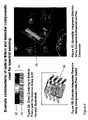
- FIG. 10illustrates an alternative embodiment showing the Smart SamplerTM with immobilized reagents in the tip or the sample housing.
- FIG. 11illustrates an example embodiment for a pipette-style design for spectral sensor.
- FIG. 12illustrates an example embodiment for a handheld design for the spectral sensor.
- FIG. 13illustrates an example embodiment of alternative design for an insertion spectral sensor.
- FIG. 14illustrates an example spectral sensor response in the visible region: colored dye solutions.
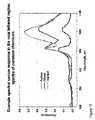
- FIG. 15illustrates an example spectral sensor response in the near infrared region spectra of common chemicals.
- the present inventionis an integrated handheld measurement system for spectral sensing of aqueous and organic solutions, certain gases and vapors, and for certain solid substrates, such as powders and extended solid surfaces.
- the sensing aspect of this inventionpreferably includes one or more miniaturized optical spectral sensors located within the body of the handheld device.
- FIG. 1provides a symbolic representation of an example spectral sensing system, comprising a light or energy source 10 , an optimized and integrated sample chamber 11 , a spectral analyzer or spectrally selective element 12 , and an integrated detection system 13 .
- Example embodiments of such spectral sensing systemsare illustrated in FIGS. 4 to 10 .
- the sourceis indicated as an incandescent-style of source, such as a tungsten source.
- the inventioncovers various types of sources, such as solid-state sources (LEDs and diode lasers), MEMs-based thermal sources and gas discharge devices, where the source is optimized for the application and the spectral range of the overall spectral measurement system.
- the optical layout shown in FIG. 1represents an energy/light transmission (or absorption) style of measurement.
- the technologyenables light scattering and optical emission measurements, such as fluorescence, phosphorescence, and luminescence, and can also be configured for reflectance and transflectance (transmission-reflection) measurements from surfaces. The latter is indicated as an example embodiment in FIG. 8 .
- the individual spectral sensorsare intended to be small and convenient to use, and can be optionally fabricated as low cost devices. As such, multiple implementations of the handheld devices can exist in the work place, or even in the home.
- An optional component of the systemis a wireless communications interface, based on a standard wireless platform, and conforming to published standards such as the IEEE 802.11b/g, ZigBee and Bluetooth.
- the system designincludes the wireless components located on the main electronics board(s) as shown, for example, in FIGS. 4 and 5 .
- the objective of the wireless componentsis to provide an easy mechanism to download results from the spectral measurement device, and to upload new calibrations and measurement schemes.
- An important component of the spectral sensor technologycan be broadly described as an optical spectrometer on a chip as represented in FIG. 2 by 14 , 15 and 16 . While optical sensors have been available, the present invention integrates an optical filter assembly 12 with a light or energy sensitive array 13 ( FIG. 1 ).
- the optical filter technology usedis either in the form of a continuous linear variable filter (LVF) 14 , 15 , or a filter array (patterned filter or mosaic) 16 .
- LVFlinear variable filter
- the resultant device or spectral sensing component 14 , 15is the most versatile and can be utilized for many applications, and for different spectral ranges, dependent on the detector array technology used.
- FIGSAn example format of an LVF-based spectral sensor is shown in FIGS.
- the spectral sensing componentis preferably implemented as part of a photodiode or a Complementary Metal-Oxide Semiconductor (CMOS) array detector package 15 .
- CMOSComplementary Metal-Oxide Semiconductor
- the LVFis directly bonded to the detector array, which preserves the spectral resolution of the LVF. In this form the assembly does not require any form of resolution retaining optics. Sensors derived from these components based on the LVF can be used for absorption measurements in the mid-range UV, long-wave UV, the visible and the short-wave near infrared (NIR), as well as fluorescence measurements in the visible and NIR.
- FIGS. 14 and 15Examples of data have been acquired in all of these modes, and example spectral response curves for the visible and NIR ranges are provided FIGS. 14 and 15 , respectively.
- the short wave NIRprovides good differentiation based on chemistry and composition based on vibrational overtones of the component molecules.
- This spectral regioncan be applied to organic and inorganic compounds, and also aqueous solutions containing high concentrations of solutes.
- the visible version for the spectral sensorcan also be used.
- the analysismay be performed with the addition of a reactive chemical reagent.
- reagent-based chemistriesare the basis for standard laboratory measurements, where the reagent and the sample are manually mixed prior to the analysis.
- the analysistypically involves a visible (color) or fluorescence based measurement.
- the reagentis immobilized within the tip of a Smart TipTM ( FIG. 9 ) or within the tip/chamber of a Smart SamplerTM ( FIG. 10 ).
- the spectral sensorcan be constructed from either a continuously variable filter (defined as the LVF) 14 or from a filter matrix or mosaic 15 .
- This latter approachis usually optically more efficient and less expensive than the LVF approach. It is often more specific in application, but less versatile than the LVF system.
- An illustrated example of a matrix-based spectral sensor 16is provided in FIGS. 2 and 3 .
- the version shownis a 4-channel RGBW (Red-Green-Blue-White) sensing device, and is capable of handling a wide range of color-based applications. Custom versions of this sensor, featuring more than 4-optically selective channels can be used.
- New technologies, involving the deposition of the wavelength selective devices on the surface of the detector elementscan be used to make application specific detection devices.
- the mosaiccan feature both the optical filter and the detector as discrete components.
- Such devicescan be assembled as hybrids, providing spectral detection in more than one spectral region, such as a combination of the UV, visible and NIR.
- An example applicationcan be for the measurement of bio-materials, such as proteins and amino acids, where one or more solid state excitation sources are used (such as 280 nm and 340 nm), and where detection is made in the UV (ca. 340 nm) and in the visible.
- the sensor hardware for the present inventionis not limited to silicon-based photo-sensing devices, and alternative detector arrays can be used, including InGaAs, PbS, PbSe, LiTaO 4 and also MEMS-based devices. Such devices would be considered for extensions into the longer wavelength NIR and for the mid-IR.
- the format of the proposed sensor platformmay be extended into these other spectral regions.
- alternative optically transparent mediamay be required for the sample chamber and the optical conduit construction, and these can include materials such as quartz, sapphire and zinc selenide.
- the onboard electronics that form part of the spectral engineprovide for the primary data acquisition from the spectral sensing/detection devices.
- the raw signal obtainedneeds to be conditioned and scaled. This is effectively a transformation from the raw signals from the physical device to a spectral based data array (or spectrum), defined in wavelength (or energy) units (x-axis) and intensity units (y-axis).
- a standardized or unified data formatis used to provide a well-defined start and end to the spectral data, and with a clearly delineated data interval (data point spacing).
- the signal handling and these primary data transformationsare shown as a symbolic representation in FIG.
- ⁇ P-1microprocessor function 1 17
- ⁇ P-2microprocessor function 2 18
- the methodswhich are downloaded into the memory (such as flash RAM) or the system, include data acquisition instructions, spectral data pre-processing, data extraction from the spectra, and also the subsequent calculations to provide the final answers.
- the flash RAMcan be either present as separate memory components, or integrated into the microprocessors. It is noted that this numerical treatment is not unique to the NIR spectral measurement range, and the onboard computing facilities defined will also be used for resolving complex mixtures in other spectral regions served by the handheld devices described in this invention.
- the component labeled ⁇ P-2 18can also handle communications and display functions. Communications can be either hardwired, such as a standard serial COM device (UART function on mP-2) or as a USB device, or as wireless communications. The latter can be incorporated as components with separate functionality from ⁇ P-2 18 .
- the display functioncan include an onboard display for the handheld sensor, and can range from a simple multi-line display to a full-scale RGB XGA or other standard display device.
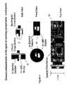
- the spectral sensing elementscan be fully integrated as a single entity or assembly on what are described as the sensing components in FIG. 4 .
- This optical sensor assembly(or opto-board) includes the light source 19 and the spectral sensing element or detector 20 , as also defined in paragraph [035]. These devices are optically isolated from each other by an optical mask fabricated from an optically opaque material 21 , such as a carbon-filled elastomer. Example embodiments are shown in FIG. 4 with circular and rectangular cross-sections. The choice of cross-section is dependent on final sensor configuration and application.
- the main system electronics board 22is directly coupled to the optical sensor assembly via either a hard connector on the back of the opto-board, or via internal cabling or flex-based connectors.
- the source and spectral detection componentsare interfaced to the sample measurement cavity (or chamber) via light pipes, light guides or light conduits.
- thisis hard coupled to the sample chamber, and is designed to minimize optical crosstalk between the light source and the detection system.
- the light guidescan be in the form of optical fibers.
- optical pathlengthscan range from 0.1 cm to 10 cm and these are considered to be optimum, dependent on the material to be measured.
- the selection of pathlengthis usually method dependent and is a function of the color density of the solutions under study.
- the longer pathlengthsmay be used for direct measurements made on organic chemicals, while shorter path lengths may be required for optically darker materials or water-based solutions.
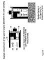
- the pathlengthis defined within the integrated construction of the sensor measurement cavity thereby providing close-coupled sample chamber 24 ( FIGS. 5 , 6 and 7 ).
- a folded path constructionas illustrated in FIGS. 5 , 6 and 7 .
- This folded pathlength 24 a and 24 bis obtained by the use of retro-reflective elements 25 located within the measurement cavity.
- the example geometryis for a transmission-based measurement. Sample emission (such as fluorescence) or light scattering (such as turbidity) measurements can require alternative geometries, where the source and detection system are orthogonal (at 90 degrees) to each other, relative to the sample chamber.
- the sampleas a liquid ( FIGS. 6 and 7 ) or as a solid ( FIG. 8 ) interacts directly with the source and detection system within the sample area.
- a reagentis involved with a liquid sample
- the reagentinteracts with the liquid outside of the sample measurement area.
- an alternativeis to feature an immobilized reagent, which is located within the light path.
- the reagentmay be included within a transparent substrate as pads 24 c in the light path within the measurement cavity ( FIG. 10 ) or on an opaque, reflective surface. In the latter case, the solid sampling approach of FIG. 8 is required for the measurement.
- Examplesare pH or test-paper measurements, where the liquid sample reacts in situ with the reagent that is immobilized in a porous solid matrix, such as a sol gel or a membrane (organic or inorganic) or an absorbent paper matrix.
- a porous solid matrixsuch as a sol gel or a membrane (organic or inorganic) or an absorbent paper matrix.
- immobilized reagentsare used and the optical measurement is made within the light path
- special tips or sample chamberswill be used with the immobilized reagent.
- the immobilized reagent substrateis located within the fluid path of the tip.
- the substrate including pads 24 cis placed at the end of the entrance (and/or exit) points of the optical light guides.
- the spectral engineis constructed as two separable parts.
- the spectral sensing components and associated electronics ( FIG. 4 ) and the sample interfacewhich is intended to be removable, and optionally disposable.
- the spectral sensing components and the electronicsare located within the main body of the sensor ( FIGS. 11 , 12 and 13 ).
- the sample chamberis located within the removable tip or sampler, which can be constructed in different forms dependent on the applications.
- the devicetakes the form of a mechanical micro pipette where the sample is transported into the sensor tip via a built-in piston pump (or equivalent). In this form, the tip is constructed with the external appearance of a pipette tip 27 ( FIG. 6 and FIG.
- the measurement moduleis independent of the sample transfer, which takes place within the completely separated sampler assembly.
- the samplerhas a common construction to a disposable pipette with a bellows (or bulb) style pumping (suction), and with the sample chamber mated on the side where the sample flow takes place.
- the liquidfills the measurement cavity by the suction process, and any residual bubbles rise into the upper flow channel (or the bellowsibulb) and out of the optical path.
- the sensorcan also be configured to measure liquids by immersion or insertion (a dip tip configuration).
- This form of sensor tiphas a two part main construction, comprising an inner optically transparent part and an external optically opaque part.
- the construction of the outside partis such that there is no light leakage from the outside into the internal sample chamber or measurement area.
- the external part of the tipis constructed to eliminate the opportunity for external (ambient) stray light to enter the measurement zone.
- both parts of the tipcan be made from plastic materials (polymers). Also, in most cases, the materials can be fabricated from some form of co-extrusion process.
- the internal reflective elements 25 for the sample chamberare to be fabricated from a reflective insert or with a reflective coating. In either case, the coating or the insert can be protected from the measurement medium by embedding within the plastic or by a protective top coat.
- the sample tip 29is designed to be open-ended.
- the spectral sensoris intended for use with solid materials, where the sensor measures the reflected light from the solid sample surface. This may be used to measure reacted test strips (pH strips, water testing strips, medical test strips, for example), color from solid surfaces (powders, extended solids and fabrics, for example), or material composition, such as a transparent coating.
- the application of the standard tips or samplers for liquidsis intended to serve either applications that involve the direct spectral measurement of liquid samples, based on their own natural color or natural absorption (UV or NIR for example) or fluorescence.
- the sensorwill work as a spectrometer or photometer for a standard reagent-based measurement, where the reagent is mixed externally with the sample prior to sampling and measurement.
- Alternative forms of tip or samplerknown as a Smart TipTM, FIG. 9 , or as a Smart SamplerTM, FIG. 10 can both be included.
- the smart tipincludes the reagent or reagents within the body of the tip.
- the reagentcan be located within the tip and/or within the measurement chamber.
- the reagentsare in an immobilized form 30 , where they are either encapsulated within a water-soluble (or solvent-soluble) medium, or they are embedded within a water/solvent permeable membrane.
- the reagentis mixed in situ as the sample is drawn into the entrance of the tip.
- the mixture of sample and reagentis then drawn through a series of vanes 31 , that provide a “tortuous” pathway, or mixing pre-chamber 31 a , where the two components (reagent(s) and sample) are thoroughly mixed and are given time to react.
- the mixed and reacted solutionis then drawn into the measurement chamber.
- the reagentcan be alternatively be immobilized within an adsorbent structure where mixing occurs by passage through the adsorbent material ( FIG. 10 , 30 / 31 ), or it can be immobilized in light transmitting pads 24 c located within the light path of the measurement chamber ( FIG. 10 ).
- the benefit of these approachesis that minimal reagent quantities are used, an ideal scenario for many modern applications in the bio-chemical and medical fields where specific reagents are extremely expensive.
- this approacheliminates any external contact with the reagents (important if the regent materials are toxic or intrinsically corrosive), and it simplifies disposal.
- the entire approachis environmentally friendly, eliminating the use of excess reagent materials and reducing the quantities of materials for disposal.
- the specific regentscan be identified by the external design or appearance of the tip, by using color coding, bar coding or by the use of a technology such as RFID.
- FIGS. 11 , 12 and 13Three example embodiments of the sensor system are illustrated, FIGS. 11 , 12 and 13 .
- the firstis the fully self-contained pipette-based version FIG. 11 , is described as the SpectraPetteTM, which includes an integrated pumping system 32 for the sample transport.
- the pumpingcan be implemented in the form of a simple piston pump.
- a mechanized pumpingbased on an electrical micro pump (rotary or piezo, for example) can be used. Note that this format can support either the standard measurement tips of the Smart Tips.
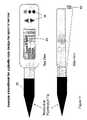
- FIG. 12A second format, where the sample is introduced via a sampler that contains the sample transport mechanism and is the form of a suction bulb or bellows, is illustrated in FIG. 12 .
- the main body of the sensoris fully self-contained and only has a light path interface with the sampler.
- the complete measurement systemis designed to be handheld, but is also designed to be freestanding on a solid surface.
- the sensoris a simpler construction because there is not the requirement for the pumping action for sample introduction ( FIG. 13 ). All sensor formats are intended to be battery-powered, where standard dry cells or rechargeable batteries are used.
- the main body of the sensorincludes a display 33 and push-button user interface controls 34 for the selection of methods, and the display of results, and a minimum set of controls.
- the displayis not limited to a three-line format, and can display graphical information as well as alpha-numerics.
- the controls 34can include functions such as power on-off, method selection, measurement activation, and transmit (for the transmission of results/data).
- Automatic featurescan include auto-power down, and auto-transmit to a local central PC for data logging, of both raw and processed spectral data.
- the approach offeredis described as being based on a spectral engine ( FIG. 1 ), which is further illustrated in its final embodiments in FIGS. 11 , 12 and 13 .
- the spectral engineincludes the spectral sensing device (described above) 14 and 15 , and the energy source 10 and 19 , which can be either a broadband or narrowband source, dependent on the mode of measurement (broadband sources are used for NIR and visible absorption, narrowband sources are used for turbidity and fluorescence). White LEDs, LED arrays and tungsten bulbs are used as example broadband sources, and individual LEDs and semiconductor laser devices are used as narrowband sources.
- Another component of the spectral engineis the sample interface, which is typically a cavity or chamber 24 .
- the sample chamberis optimized in size based on the physical dimensions of the spectral engine sample interface.
- the sizes of the detection devicesare, for example, 1 mm ⁇ 8 mm 15 and approximately 3 mm ⁇ 3 mm (matrix sensor 16 ). Scaling the sample cell to these physical dimensions can produce sample chamber volumes as low as 80 microliters.
- the advantage gained hereis that a minimum sample size is required, which effectively eliminates any sample temperature effects, and significantly reduces the amount of reagents that have to be dispensed for reagent-based applications.
- the volume requirement for reagentscan be reduced down by as much as 1000 times, which reduces reagent consumption and operating costs.
- the final critical set of components of the spectral engineis the electronics.
- FIG. 3An example of the functional electronics is provided in FIG. 3 , which are physically located within the total sensor body as illustrated in FIGS. 5 to 8 as 22 .
- the final processor 18can feature onboard memory to store methods, calibrations and results, and can handle communications to displays (if required), external devices via serial connections and also wireless communications if the option is used.
- a single advanced processoris a practical alternative to the two processor format.
- the spectral sensor implementationis based on basic two-part construction featuring the main spectral sensing system, with common display and controls, and a disposable component; a tip FIGS. 11 and 13 , or a sampler FIG. 12 .
- Two main formatsare offered; one with sample transport, in the format of a micro-pipette ( FIG. 11 ) or a disposable pipette ( FIG. 12 ), and the other as a dip (insertion) or surface measurement device ( FIG. 13 ).
- the function of the sensoris defined in terms of the tip or sampler ( 27 , 28 or 29 ), and the method of measurement selected from the integrated display 33 .
Landscapes
- Physics & Mathematics (AREA)
- Spectroscopy & Molecular Physics (AREA)
- General Physics & Mathematics (AREA)
- Health & Medical Sciences (AREA)
- Life Sciences & Earth Sciences (AREA)
- Chemical & Material Sciences (AREA)
- Biochemistry (AREA)
- General Health & Medical Sciences (AREA)
- Analytical Chemistry (AREA)
- Immunology (AREA)
- Pathology (AREA)
- Nuclear Medicine, Radiotherapy & Molecular Imaging (AREA)
- Engineering & Computer Science (AREA)
- Human Computer Interaction (AREA)
- Molecular Biology (AREA)
- Investigating, Analyzing Materials By Fluorescence Or Luminescence (AREA)
- Investigating Or Analysing Materials By Optical Means (AREA)
Abstract
Description
Claims (24)
Priority Applications (2)
| Application Number | Priority Date | Filing Date | Title |
|---|---|---|---|
| US11/605,869US7459713B2 (en) | 2003-08-14 | 2006-11-29 | Integrated sensing system approach for handheld spectral measurements having a disposable sample handling apparatus |
| US12/136,219US7907282B2 (en) | 2003-08-14 | 2008-06-10 | Integrated sensing module for handheld spectral measurements |
Applications Claiming Priority (5)
| Application Number | Priority Date | Filing Date | Title |
|---|---|---|---|
| US49497703P | 2003-08-14 | 2003-08-14 | |
| US10/913,819US7057156B2 (en) | 2003-08-14 | 2004-08-06 | System and method for integrated sensing and control of industrial processes |
| US74085005P | 2005-11-30 | 2005-11-30 | |
| US11/355,908US20060284058A1 (en) | 2003-08-14 | 2006-02-16 | System and method for integrated sensing and control of industrial processes |
| US11/605,869US7459713B2 (en) | 2003-08-14 | 2006-11-29 | Integrated sensing system approach for handheld spectral measurements having a disposable sample handling apparatus |
Related Parent Applications (2)
| Application Number | Title | Priority Date | Filing Date |
|---|---|---|---|
| US10/913,819Continuation-In-PartUS7057156B2 (en) | 2003-08-14 | 2004-08-06 | System and method for integrated sensing and control of industrial processes |
| US11/355,908Continuation-In-PartUS20060284058A1 (en) | 2003-08-14 | 2006-02-16 | System and method for integrated sensing and control of industrial processes |
Related Child Applications (1)
| Application Number | Title | Priority Date | Filing Date |
|---|---|---|---|
| US12/136,219DivisionUS7907282B2 (en) | 2003-08-14 | 2008-06-10 | Integrated sensing module for handheld spectral measurements |
Publications (2)
| Publication Number | Publication Date |
|---|---|
| US20070084990A1 US20070084990A1 (en) | 2007-04-19 |
| US7459713B2true US7459713B2 (en) | 2008-12-02 |
Family
ID=46326694
Family Applications (2)
| Application Number | Title | Priority Date | Filing Date |
|---|---|---|---|
| US11/605,869Expired - Fee RelatedUS7459713B2 (en) | 2003-08-14 | 2006-11-29 | Integrated sensing system approach for handheld spectral measurements having a disposable sample handling apparatus |
| US12/136,219Expired - Fee RelatedUS7907282B2 (en) | 2003-08-14 | 2008-06-10 | Integrated sensing module for handheld spectral measurements |
Family Applications After (1)
| Application Number | Title | Priority Date | Filing Date |
|---|---|---|---|
| US12/136,219Expired - Fee RelatedUS7907282B2 (en) | 2003-08-14 | 2008-06-10 | Integrated sensing module for handheld spectral measurements |
Country Status (1)
| Country | Link |
|---|---|
| US (2) | US7459713B2 (en) |
Cited By (21)
| Publication number | Priority date | Publication date | Assignee | Title |
|---|---|---|---|---|
| US20110212538A1 (en)* | 2008-10-06 | 2011-09-01 | Hach Lange Gmbh | Method for determining an analyte in a water sample by means of a mobile water analysis arrangement |
| WO2012012171A1 (en)* | 2010-07-19 | 2012-01-26 | Andalyze, Inc. | Portable fluorimetric apparatus, method and system |
| US8690934B2 (en) | 2011-05-09 | 2014-04-08 | The Invention Science Fund I, Llc | Method, device and system for modulating an activity of brown adipose tissue in a vertebrate subject |
| US8810417B2 (en) | 2009-08-28 | 2014-08-19 | The Invention Science Fund I, Llc | Beverage immersate with detection capability |
| US8815156B2 (en) | 2010-07-19 | 2014-08-26 | Andalyze, Inc. | Sensor housing and reagent chemistry |
| US8951472B2 (en) | 2010-07-19 | 2015-02-10 | Andalyze, Inc. | Portable fluorimetric apparatus, method and system |
| US9024766B2 (en) | 2009-08-28 | 2015-05-05 | The Invention Science Fund, Llc | Beverage containers with detection capability |
| US9180449B2 (en) | 2012-06-12 | 2015-11-10 | Hach Company | Mobile water analysis |
| US9182353B2 (en) | 2010-07-22 | 2015-11-10 | Hach Company | Lab-on-a-chip for alkalinity analysis |
| WO2015112919A3 (en)* | 2014-01-23 | 2015-11-19 | Spectrum Perception Llc | Miniaturized spectrometer for sensitive and robust use |
| US9238133B2 (en) | 2011-05-09 | 2016-01-19 | The Invention Science Fund I, Llc | Method, device and system for modulating an activity of brown adipose tissue in a vertebrate subject |
| US9322773B2 (en) | 2011-06-07 | 2016-04-26 | Measurement Specialties, Inc. | Optical sensing device for fluid sensing and methods therefor |
| USD768872S1 (en) | 2012-12-12 | 2016-10-11 | Hach Company | Cuvette for a water analysis instrument |
| US20170024633A1 (en)* | 2012-08-21 | 2017-01-26 | James A. Negro | Trainable handheld optical character recognition systems and methods |
| US9814339B2 (en) | 2013-08-01 | 2017-11-14 | Drexel University | Device to measure and monitor drinking and eating having a cup holder with a digital camera |
| EP3643355A1 (en) | 2014-06-03 | 2020-04-29 | Pop Test Abuse Deterrent Technology LLC | Drug device configured for wireless communication |
| US10710067B2 (en) | 2014-01-23 | 2020-07-14 | Spectrum Perception Llc | Pipette tip with integrated light guides in the body and method of spectroscopic analysis using same |
| US10761015B1 (en)* | 2019-09-18 | 2020-09-01 | Taiwan Redeye Biomedical Inc. | Handheld hemoglobin detecting device |
| US10974241B2 (en) | 2017-03-30 | 2021-04-13 | TE Connectivity Services Gmbh | Fluid sensing system |
| US11307148B2 (en)* | 2016-01-18 | 2022-04-19 | Saam, Inc. | Sensor system for multi-component fluids |
| WO2025064425A1 (en)* | 2023-09-18 | 2025-03-27 | Siemens Healthcare Diagnostics Inc. | A system for analyzing bio-samples |
Families Citing this family (52)
| Publication number | Priority date | Publication date | Assignee | Title |
|---|---|---|---|---|
| WO2008154020A1 (en)* | 2007-06-11 | 2008-12-18 | Frank Hartley | Non-invasive qualitative measurements of chemistry of blood and bodily fluids |
| DE102008019500B4 (en)* | 2007-09-20 | 2010-06-02 | Technische Universität München | Anorndnung, method and sensor for detecting liquid parameters |
| FR2922306B1 (en)* | 2007-10-12 | 2009-11-20 | Sp3H | SPECTROMETRY DEVICE FOR ANALYSIS OF A FLUID |
| FR2922303B1 (en)* | 2007-10-12 | 2010-05-07 | Sp3H | SPECTROMETRY DEVICE FOR ANALYSIS OF A FLUID |
| FR2922304B1 (en)* | 2007-10-12 | 2009-11-20 | Sp3H | SPECTROMETRY DEVICE FOR ANALYSIS OF A FLUID |
| WO2009060412A2 (en)* | 2007-11-07 | 2009-05-14 | Nxp B.V. | Method and system for bio-analysis using a mobile communication device |
| EP3556291B1 (en)* | 2008-08-07 | 2025-05-14 | University of Massachusetts | Spectroscopic sensors |
| EP2293032A1 (en) | 2009-09-04 | 2011-03-09 | Radisens Diagnostic Limited | An Integrated Cytometric Sensor System and Method |
| WO2011043996A1 (en)* | 2009-10-06 | 2011-04-14 | Molecular Biometrics, Inc. | Verifying, via radio-frequency identification, completeness of a sample analysis in a chemical analytical procedure |
| DE102010010610A1 (en)* | 2010-03-08 | 2011-09-08 | Pulsion Medical Systems Ag | Portable sensor device and patient monitor |
| US8248611B2 (en)* | 2010-03-31 | 2012-08-21 | Ecolab Usa Inc. | Handheld optical measuring device and method of use |
| US20140247442A1 (en)* | 2010-07-27 | 2014-09-04 | Microptix Technologies, Llc | Spectroradiometer device and applications of same |
| US9414930B2 (en)* | 2010-10-26 | 2016-08-16 | Kyphon SÀRL | Activatable devices containing a chemonucleolysis agent |
| GB2492120A (en) | 2011-06-22 | 2012-12-26 | Melexis Tessenderlo Nv | Spectrum analyzing sensor with filter glued in cavity of sensing package |
| KR101356176B1 (en)* | 2011-08-30 | 2014-01-28 | 한국화학연구원 | Method and system for measuring engine oil deterioration |
| JP2014532873A (en) | 2011-11-03 | 2014-12-08 | ベリフード リミテッド | Low-cost spectroscopic analysis system for end-user food analysis |
| US8873892B2 (en)* | 2012-08-21 | 2014-10-28 | Cognex Corporation | Trainable handheld optical character recognition systems and methods |
| TWI593950B (en) | 2012-11-13 | 2017-08-01 | 唯亞威方案公司 | Portable spectrometer |
| US9885655B2 (en) | 2012-11-13 | 2018-02-06 | Viavi Solutions Inc. | Spectrometer with a relay lightpipe |
| CN105593651B (en) | 2013-08-02 | 2019-06-07 | 威利食品有限公司 | Spectrometric system and method, spectroscopy equipment and system |
| FR3009621B1 (en)* | 2013-08-09 | 2017-04-28 | Novacyt | METHOD AND APPARATUS FOR PREPARING A CELLULAR CONTAINER COMPRISING MEANS FOR PRE-ANALYSIS OF A SAMPLE RECEIVED |
| US20170160189A1 (en)* | 2013-11-27 | 2017-06-08 | Cirtemo, Llc | Optical analysis system and process |
| WO2015101992A2 (en) | 2014-01-03 | 2015-07-09 | Verifood, Ltd. | Spectrometry systems, methods, and applications |
| US9625628B2 (en) | 2014-01-31 | 2017-04-18 | Viavi Solutions Inc. | Optical filter and spectrometer |
| US10107686B1 (en) | 2014-03-03 | 2018-10-23 | Ayalytical Instruments, Inc. | Vision strip analyzer |
| US20150276594A1 (en)* | 2014-03-26 | 2015-10-01 | Intellectual Property Transfer, LLC | Method and apparatus for measuring turbidity |
| WO2016063284A2 (en) | 2014-10-23 | 2016-04-28 | Verifood, Ltd. | Accessories for handheld spectrometer |
| WO2016071356A1 (en)* | 2014-11-05 | 2016-05-12 | Medico-Chemical Lab. Aps | A ballast water analysis system |
| WO2016125164A2 (en) | 2015-02-05 | 2016-08-11 | Verifood, Ltd. | Spectrometry system applications |
| WO2016125165A2 (en) | 2015-02-05 | 2016-08-11 | Verifood, Ltd. | Spectrometry system with visible aiming beam |
| WO2016162865A1 (en) | 2015-04-07 | 2016-10-13 | Verifood, Ltd. | Detector for spectrometry system |
| US10180339B1 (en)* | 2015-05-08 | 2019-01-15 | Digimarc Corporation | Sensing systems |
| US10066990B2 (en) | 2015-07-09 | 2018-09-04 | Verifood, Ltd. | Spatially variable filter systems and methods |
| US9945790B2 (en) | 2015-08-05 | 2018-04-17 | Viavi Solutions Inc. | In-situ spectral process monitoring |
| US10048127B2 (en) | 2015-08-05 | 2018-08-14 | Viavi Solutions Inc. | Optical filter and spectrometer |
| US9638628B2 (en) | 2015-08-27 | 2017-05-02 | General Electric Company | Gas analysis system and method |
| US10613096B2 (en) | 2015-08-28 | 2020-04-07 | Captl Llc | Multi-spectral microparticle-fluorescence photon cytometry |
| US20170146450A1 (en)* | 2015-11-19 | 2017-05-25 | Sentelligence, Inc. | Species specific sensor for exhaust gases and method thereof |
| US10203246B2 (en) | 2015-11-20 | 2019-02-12 | Verifood, Ltd. | Systems and methods for calibration of a handheld spectrometer |
| US10241095B2 (en) | 2015-11-23 | 2019-03-26 | Sentelligence, Inc. | Multi-component gas and vapor monitoring sensor |
| US10254215B2 (en) | 2016-04-07 | 2019-04-09 | Verifood, Ltd. | Spectrometry system applications |
| WO2018015951A1 (en)* | 2016-07-20 | 2018-01-25 | Verifood, Ltd. | Accessories for handheld spectrometer |
| US10791933B2 (en) | 2016-07-27 | 2020-10-06 | Verifood, Ltd. | Spectrometry systems, methods, and applications |
| US11187584B2 (en) | 2017-04-13 | 2021-11-30 | Captl Llc | Photon counting and spectroscopy |
| JP6919603B2 (en) | 2018-03-12 | 2021-08-18 | オムロン株式会社 | Wavelength detector and confocal measuring device |
| WO2019190122A1 (en) | 2018-03-30 | 2019-10-03 | 삼성전자 주식회사 | Electronic device for acquiring state information on object, and control method therefor |
| AU2019279025A1 (en)* | 2018-06-01 | 2021-01-07 | Orb Xyz, Inc. | Detecting an analyte in a medium |
| CN109211803B (en)* | 2018-09-17 | 2020-10-09 | 中国科学院生态环境研究中心 | A device for rapid identification of microplastics based on microscopic multispectral technology |
| CN113167648A (en) | 2018-10-08 | 2021-07-23 | 威利食品有限公司 | an accessory for a spectrometer |
| CN111474361B (en)* | 2020-05-25 | 2024-12-20 | 山西瑞豪生物科技有限公司 | A portable immunochromatographic test strip quantitative detection device with multi-spectral modulation |
| KR20220025378A (en) | 2020-08-24 | 2022-03-03 | 삼성전자주식회사 | Apparatus and method for acquring target signal spectrum |
| KR20220070792A (en) | 2020-11-23 | 2022-05-31 | 삼성전자주식회사 | Apparatus and method for estimating body core temperature, and healthcare device |
Citations (87)
| Publication number | Priority date | Publication date | Assignee | Title |
|---|---|---|---|---|
| US2649011A (en) | 1949-07-29 | 1953-08-18 | Standard Oil Dev Co | Analytical sample cell |
| US3364812A (en) | 1963-09-05 | 1968-01-23 | Foxboro Co | Continuous flow turbidimeter |
| US3370502A (en) | 1963-11-05 | 1968-02-27 | Wilks Scientific Corp | Frustrated multiple internal reflection rod with variable length fluid containing enclosure means |
| US3460893A (en) | 1965-09-15 | 1969-08-12 | Wilks Scientific Corp | Apparatus for analyzing a continuously moving strip by means of attenuated total reflection |
| US3508830A (en) | 1967-11-13 | 1970-04-28 | Shell Oil Co | Apparatus for light scattering measurements |
| US3578865A (en) | 1968-10-03 | 1971-05-18 | Mobil Oil Corp | Method and apparatus for photo-electrically monitoring the degradation of an oil stream |
| US3619072A (en) | 1969-03-24 | 1971-11-09 | Mobil Oil Corp | Fluid sample cell with quick purging means |
| US3665201A (en) | 1968-12-23 | 1972-05-23 | Gam Rad | Turbidimeter utilizing back scatter |
| US3713743A (en) | 1970-11-25 | 1973-01-30 | Agricultural Control Syst | Forward scatter optical turbidimeter apparatus |
| US3714444A (en) | 1970-07-16 | 1973-01-30 | Keene Corp | Suspended solids analyzer |
| US3734629A (en) | 1970-06-26 | 1973-05-22 | V Griffiths | Instrument for determining the optical density of fluids |
| US3790279A (en) | 1971-09-28 | 1974-02-05 | Environment One Corp | Oil contamination monitor with digital signal processing |
| US3876307A (en) | 1969-08-05 | 1975-04-08 | Environmental Technology | Optical fluid contamination and change monitor |
| US3892485A (en) | 1974-05-06 | 1975-07-01 | Gen Electric | Monitoring apparatus for measuring particles suspended in liquid and for measuring the opacity of the liquid |
| JPS57142546A (en) | 1981-02-28 | 1982-09-03 | Shimadzu Corp | Infrared multiple reflection type oil concentration measuring apparatus |
| US4365303A (en) | 1980-02-07 | 1982-12-21 | The Perkin-Elmer Corporation | Method and apparatus for determining the nature of an unknown chemical substance |
| US4441971A (en) | 1979-09-20 | 1984-04-10 | Kabushiki Kaisha Toyota Chuo Kenkyusho | Process and apparatus for reducing soot |
| JPS60111946A (en) | 1983-11-22 | 1985-06-18 | Matsushita Electric Ind Co Ltd | Optical liquid sensor |
| US4570069A (en) | 1982-12-30 | 1986-02-11 | Gager Dennis J | On-board electronic oil contamination detector for vehicle engines |
| US4595833A (en) | 1983-09-20 | 1986-06-17 | Sting Donald W | Multiple internal reflection cell optical system for use in infrared spectrophotometry of liquid and fluidized samples |
| JPS61213479A (en) | 1985-03-19 | 1986-09-22 | 大川 秀利 | Hollow drying method of wood |
| EP0206433A2 (en) | 1985-06-25 | 1986-12-30 | The Dow Chemical Company | Methods for measuring the light absorbance of a fluid medium |
| US4649711A (en) | 1985-09-03 | 1987-03-17 | Carrier Corporation | Apparatus and method for infrared optical electronic qualitative analysis of a fluid independent of the temperature thereof |
| US4699509A (en) | 1984-04-21 | 1987-10-13 | Nippon Soken, Inc. | Device for measuring contamination of lubricant |
| US4701838A (en) | 1983-05-12 | 1987-10-20 | The Broken Hill Proprietary Co., Ltd. | Characterizing and handling multi-component substances |
| WO1988002109A1 (en) | 1986-09-15 | 1988-03-24 | Hughes Aircraft Company | System for sensing ions in aqueous solution |
| JPS63266342A (en) | 1987-04-24 | 1988-11-02 | Komatsu Ltd | Oil deterioration level detection device |
| JPH02259548A (en) | 1989-03-31 | 1990-10-22 | Shiroki Corp | Liquid concentration meter |
| US4975581A (en) | 1989-06-21 | 1990-12-04 | University Of New Mexico | Method of and apparatus for determining the similarity of a biological analyte from a model constructed from known biological fluids |
| US5000569A (en) | 1988-12-28 | 1991-03-19 | Lamb-Weston, Inc. | Light reflection defect detection apparatus and method using pulsed light-emitting semiconductor devices of different wavelengths |
| JPH03111741A (en) | 1989-09-27 | 1991-05-13 | Nippondenso Co Ltd | Optical sensor |
| US5021665A (en) | 1989-12-26 | 1991-06-04 | Ames Donald P | Oil level monitor |
| JPH03142349A (en) | 1989-10-30 | 1991-06-18 | Toyota Motor Corp | Detector for deterioration of lubricating oil |
| US5049742A (en) | 1989-11-16 | 1991-09-17 | Kyodo Oil Technical Research Co., Ltd. | Apparatus for detecting deterioration of engine oil |
| US5050946A (en) | 1990-09-27 | 1991-09-24 | Compaq Computer Corporation | Faceted light pipe |
| US5051551A (en) | 1989-05-18 | 1991-09-24 | Axiom Analytical, Inc. | Immersion probe for infrared internal reflectance spectroscopy |
| US5071527A (en) | 1990-06-29 | 1991-12-10 | University Of Dayton | Complete oil analysis technique |
| US5077477A (en) | 1990-12-12 | 1991-12-31 | Richard Stroman | Method and apparatus for detecting pits in fruit |
| US5076397A (en) | 1989-08-30 | 1991-12-31 | Sanshin Kogyo Kabushiki Kaisha | Oil condition checking system for marine propulsion unit |
| US5089780A (en) | 1989-10-04 | 1992-02-18 | Hughes Aircraft Company | Oil quality monitor sensor and system |
| US5125742A (en) | 1990-07-25 | 1992-06-30 | General Analysis Corporation | Long path gas absorption cell |
| US5185640A (en) | 1991-09-13 | 1993-02-09 | Genral Analysis Corporation | Multifaceted probes for optical analysis |
| US5196898A (en) | 1989-03-27 | 1993-03-23 | Tatsuta Electric Wire And Cable Co., Ltd. | Optical liquid sensor, a method of manufacturing the same, and an automotive oil/battery checker employing the sensor |
| US5278426A (en) | 1993-01-21 | 1994-01-11 | Barbier William J | Optical liquid level sensor for pressurized systems utilizing prismatic element |
| US5296843A (en) | 1991-03-28 | 1994-03-22 | Sd Laboratories, Inc. | Fluid or vapor diagnostic device |
| US5407830A (en) | 1993-12-01 | 1995-04-18 | Mobil Oil Corporation | Control of low inventory alkylation unit |
| US5438420A (en) | 1993-08-09 | 1995-08-01 | Vickers, Incorporated | Monitoring of fluid contamination level wherein the light energy is focused on the fluid passage means |
| US5440126A (en) | 1991-04-26 | 1995-08-08 | British Technology Group Ltd. | Optical probe heads |
| US5442435A (en) | 1994-03-24 | 1995-08-15 | Nartron Corporation | Fluid composition sensor using reflected or refracted light monitoring |
| US5452083A (en) | 1994-04-25 | 1995-09-19 | Wilks, Jr.; Paul A. | Multiple internal reflection optical analyzers not requiring external optics |
| JPH07280720A (en) | 1994-04-13 | 1995-10-27 | Nippondenso Co Ltd | Concentration detecting device |
| JPH0862207A (en) | 1994-08-22 | 1996-03-08 | Japan Energy Corp | Lubricant deterioration detection method |
| US5512757A (en) | 1992-04-06 | 1996-04-30 | Rosemount Analytical, Inc. | Spectrophotometer and optical system therefor |
| US5534708A (en) | 1993-12-15 | 1996-07-09 | Simmonds Precision Products Inc. | Optical fuel/air/water sensor and detector circuit |
| JPH08201278A (en) | 1995-01-20 | 1996-08-09 | Shimadzu Corp | Spectrum measuring device |
| US5548393A (en) | 1993-07-05 | 1996-08-20 | Nippondenso Co., Ltd. | Oil deterioration detection apparatus and apparatus for detecting particles in liquid |
| US5608518A (en) | 1994-04-25 | 1997-03-04 | Wilks, Jr.; Paul A. | Multiple internal reflection analyzers not requiring external optics |
| EP0797091A1 (en) | 1996-03-19 | 1997-09-24 | Texas Instruments Incorporated | Surface plasmon resonance sensor with interchangable optical element |
| US5739916A (en) | 1995-12-04 | 1998-04-14 | University Of Alabama At Huntsville | Apparatus and method for determining the concentration of species in a substance |
| EP0836092A2 (en) | 1996-10-01 | 1998-04-15 | Texas Instruments Inc. | An optical sensor |
| US5741961A (en) | 1993-08-18 | 1998-04-21 | Sandia Corporation | Quartz resonator fluid density and viscosity monitor |
| US5790246A (en) | 1996-04-18 | 1998-08-04 | Montores Pty. Ltd. | Apparatus and network for determining a parameter of a particle in a fluid employing detector and processor |
| KR0150054B1 (en) | 1994-10-19 | 1998-12-01 | 김은영 | Online Diagnosis Method and Apparatus for Wear Particles in Lubricant |
| US5889683A (en) | 1996-04-22 | 1999-03-30 | Ismail; Ashraf A. | Method and apparatus for continuous oil monitoring and treatment |
| US5939727A (en) | 1997-12-22 | 1999-08-17 | Caterpillar Inc. | Contamination sensor |
| US6040578A (en) | 1996-02-02 | 2000-03-21 | Instrumentation Metrics, Inc. | Method and apparatus for multi-spectral analysis of organic blood analytes in noninvasive infrared spectroscopy |
| US6043505A (en) | 1998-08-06 | 2000-03-28 | Ames; Donald P. | Device and method for monitoring fluids with a detection of cross sectional shape of transmitted beam |
| US6049088A (en) | 1998-01-09 | 2000-04-11 | Scully Signal Company | Fluid overfill probe with anti-reflective guard |
| US6091484A (en) | 1997-05-23 | 2000-07-18 | Col-Ven S.A. | Oil quantity and quality indicator |
| GB2346691A (en) | 1999-02-09 | 2000-08-16 | Liquip Sales Pty Limited | Fluid detector |
| US6118520A (en) | 1996-12-18 | 2000-09-12 | The Dow Chemical Company | Dual analysis probe |
| US6138082A (en) | 1996-12-20 | 2000-10-24 | The Perkin Elmer Corporation | Standardizing between analytical instruments |
| US6151108A (en) | 1998-08-31 | 2000-11-21 | Korea Institute Of Science And Technology | On-line measurement of contaminant level in lubricating oil |
| US6324418B1 (en)* | 1997-09-29 | 2001-11-27 | Boston Scientific Corporation | Portable tissue spectroscopy apparatus and method |
| US6331704B1 (en) | 1998-01-20 | 2001-12-18 | Vickers, Incorporated | Hydraulic fluid contamination monitor |
| US6383209B1 (en)* | 1997-09-29 | 2002-05-07 | Boston Scientific Corporation | Sheath for tissue spectroscopy |
| US6388251B1 (en) | 1999-01-12 | 2002-05-14 | Baker Hughes, Inc. | Optical probe for analysis of formation fluids |
| US20020069021A1 (en) | 1998-02-02 | 2002-06-06 | Hitachi Ltd. | Automobile oil deterioration diagnosing apparatus |
| US6420708B2 (en) | 2000-03-10 | 2002-07-16 | Wilks Enterprise, Inc. | Spectroscopy analyzer using a detector array |
| US6452179B1 (en) | 1998-08-14 | 2002-09-17 | Global Technovations, Inc. | On-site analyzer |
| US6559941B1 (en) | 1998-12-03 | 2003-05-06 | Varian Australia Pty. Ltd. | UV-VIS spectrophotometry |
| US20030154044A1 (en) | 2001-07-23 | 2003-08-14 | Lundstedt Alan P. | On-site analysis system with central processor and method of analyzing |
| US6690452B2 (en) | 2001-04-18 | 2004-02-10 | Paul A. Wilks, Jr. | Monitor having a polymer internal reflective element |
| US20040201835A1 (en) | 2001-10-11 | 2004-10-14 | John Coates | Low-cost on-line and in-line spectral sensors based on solid-state source and detectors combinations for monitoring lubricants and functional fluids |
| US6872947B1 (en)* | 2003-09-22 | 2005-03-29 | Lucent Technologies Inc. | MEMS-based spectrophotometric system |
| US20050088653A1 (en) | 2003-08-14 | 2005-04-28 | Microspectral Sensing, Llc | System and method for integrated sensing and control of industrial processes |
| US20070239367A1 (en) | 2004-02-05 | 2007-10-11 | Medpro Holdings, Llc | On-site method of providing analysis of potency and purity of pharmaceutical compounds |
Family Cites Families (18)
| Publication number | Priority date | Publication date | Assignee | Title |
|---|---|---|---|---|
| US4054389A (en)* | 1976-09-23 | 1977-10-18 | International Business Machines Corporation | Spectrophotometer with photodiode array |
| JPS61213749A (en) | 1985-03-20 | 1986-09-22 | Nippon Soken Inc | Apparatus for detecting turbidity of lubricant |
| US4957371A (en)* | 1987-12-11 | 1990-09-18 | Santa Barbara Research Center | Wedge-filter spectrometer |
| US5166755A (en)* | 1990-05-23 | 1992-11-24 | Nahum Gat | Spectrometer apparatus |
| JP3142349B2 (en) | 1991-03-04 | 2001-03-07 | 輝彦 別府 | Composite plasmid vector and transformed microorganism |
| US5319437A (en)* | 1991-07-26 | 1994-06-07 | Kollmorgen Corporation | Handheld portable spectrophotometer |
| US5568186A (en) | 1993-11-15 | 1996-10-22 | The United States Of America As Represented By The Secretary Of The Army | Focal plane filtered multispectral multidetector imager |
| US6197503B1 (en) | 1997-11-26 | 2001-03-06 | Ut-Battelle, Llc | Integrated circuit biochip microsystem containing lens |
| US6094604A (en) | 1998-03-06 | 2000-07-25 | Honeywell Measurex Devron Inc. | Coordinated control of sheet properties by receiving a measured and broadcasted properties data, determining a control action, and broadcasting a predicted changes to other actuators |
| US6057925A (en)* | 1998-08-28 | 2000-05-02 | Optical Coating Laboratory, Inc. | Compact spectrometer device |
| US6332573B1 (en)* | 1998-11-10 | 2001-12-25 | Ncr Corporation | Produce data collector and produce recognition system |
| US6290816B1 (en) | 1999-07-21 | 2001-09-18 | Voith Sulzer Paper Technology North America, Inc. | Paper machine with closed loop control system |
| US6501547B1 (en)* | 2000-02-18 | 2002-12-31 | Ncr Corporation | Hand-held produce recognition system and produce data collector |
| US6630999B2 (en)* | 2001-05-01 | 2003-10-07 | Optical Coating Laboratory, Inc. | Color measuring sensor assembly for spectrometer devices |
| US7248297B2 (en) | 2001-11-30 | 2007-07-24 | The Board Of Trustees Of The Leland Stanford Junior University | Integrated color pixel (ICP) |
| US20100134794A1 (en) | 2004-02-05 | 2010-06-03 | Medpro Holdings, Llc | Analyzer for determining the concentration, potency and purity of pharmaceutical compounds |
| EP1875128B1 (en) | 2005-04-25 | 2018-12-26 | University of Massachusetts | Systems and methods for correcting optical reflectance measurements |
| EP3556291B1 (en) | 2008-08-07 | 2025-05-14 | University of Massachusetts | Spectroscopic sensors |
- 2006
- 2006-11-29USUS11/605,869patent/US7459713B2/ennot_activeExpired - Fee Related
- 2008
- 2008-06-10USUS12/136,219patent/US7907282B2/ennot_activeExpired - Fee Related
Patent Citations (94)
| Publication number | Priority date | Publication date | Assignee | Title |
|---|---|---|---|---|
| US2649011A (en) | 1949-07-29 | 1953-08-18 | Standard Oil Dev Co | Analytical sample cell |
| US3364812A (en) | 1963-09-05 | 1968-01-23 | Foxboro Co | Continuous flow turbidimeter |
| US3370502A (en) | 1963-11-05 | 1968-02-27 | Wilks Scientific Corp | Frustrated multiple internal reflection rod with variable length fluid containing enclosure means |
| US3460893A (en) | 1965-09-15 | 1969-08-12 | Wilks Scientific Corp | Apparatus for analyzing a continuously moving strip by means of attenuated total reflection |
| US3508830A (en) | 1967-11-13 | 1970-04-28 | Shell Oil Co | Apparatus for light scattering measurements |
| US3578865A (en) | 1968-10-03 | 1971-05-18 | Mobil Oil Corp | Method and apparatus for photo-electrically monitoring the degradation of an oil stream |
| US3665201A (en) | 1968-12-23 | 1972-05-23 | Gam Rad | Turbidimeter utilizing back scatter |
| US3619072A (en) | 1969-03-24 | 1971-11-09 | Mobil Oil Corp | Fluid sample cell with quick purging means |
| US3876307A (en) | 1969-08-05 | 1975-04-08 | Environmental Technology | Optical fluid contamination and change monitor |
| US3734629A (en) | 1970-06-26 | 1973-05-22 | V Griffiths | Instrument for determining the optical density of fluids |
| US3714444A (en) | 1970-07-16 | 1973-01-30 | Keene Corp | Suspended solids analyzer |
| US3713743A (en) | 1970-11-25 | 1973-01-30 | Agricultural Control Syst | Forward scatter optical turbidimeter apparatus |
| US3790279A (en) | 1971-09-28 | 1974-02-05 | Environment One Corp | Oil contamination monitor with digital signal processing |
| US3892485A (en) | 1974-05-06 | 1975-07-01 | Gen Electric | Monitoring apparatus for measuring particles suspended in liquid and for measuring the opacity of the liquid |
| US4441971A (en) | 1979-09-20 | 1984-04-10 | Kabushiki Kaisha Toyota Chuo Kenkyusho | Process and apparatus for reducing soot |
| US4365303A (en) | 1980-02-07 | 1982-12-21 | The Perkin-Elmer Corporation | Method and apparatus for determining the nature of an unknown chemical substance |
| JPS57142546A (en) | 1981-02-28 | 1982-09-03 | Shimadzu Corp | Infrared multiple reflection type oil concentration measuring apparatus |
| US4570069A (en) | 1982-12-30 | 1986-02-11 | Gager Dennis J | On-board electronic oil contamination detector for vehicle engines |
| US4701838A (en) | 1983-05-12 | 1987-10-20 | The Broken Hill Proprietary Co., Ltd. | Characterizing and handling multi-component substances |
| US4595833A (en) | 1983-09-20 | 1986-06-17 | Sting Donald W | Multiple internal reflection cell optical system for use in infrared spectrophotometry of liquid and fluidized samples |
| JPS60111946A (en) | 1983-11-22 | 1985-06-18 | Matsushita Electric Ind Co Ltd | Optical liquid sensor |
| US4699509A (en) | 1984-04-21 | 1987-10-13 | Nippon Soken, Inc. | Device for measuring contamination of lubricant |
| JPS61213479A (en) | 1985-03-19 | 1986-09-22 | 大川 秀利 | Hollow drying method of wood |
| EP0206433A2 (en) | 1985-06-25 | 1986-12-30 | The Dow Chemical Company | Methods for measuring the light absorbance of a fluid medium |
| US4649711A (en) | 1985-09-03 | 1987-03-17 | Carrier Corporation | Apparatus and method for infrared optical electronic qualitative analysis of a fluid independent of the temperature thereof |
| WO1988002109A1 (en) | 1986-09-15 | 1988-03-24 | Hughes Aircraft Company | System for sensing ions in aqueous solution |
| JPS63266342A (en) | 1987-04-24 | 1988-11-02 | Komatsu Ltd | Oil deterioration level detection device |
| US5000569A (en) | 1988-12-28 | 1991-03-19 | Lamb-Weston, Inc. | Light reflection defect detection apparatus and method using pulsed light-emitting semiconductor devices of different wavelengths |
| US5196898A (en) | 1989-03-27 | 1993-03-23 | Tatsuta Electric Wire And Cable Co., Ltd. | Optical liquid sensor, a method of manufacturing the same, and an automotive oil/battery checker employing the sensor |
| JPH02259548A (en) | 1989-03-31 | 1990-10-22 | Shiroki Corp | Liquid concentration meter |
| US5051551A (en) | 1989-05-18 | 1991-09-24 | Axiom Analytical, Inc. | Immersion probe for infrared internal reflectance spectroscopy |
| US4975581A (en) | 1989-06-21 | 1990-12-04 | University Of New Mexico | Method of and apparatus for determining the similarity of a biological analyte from a model constructed from known biological fluids |
| US5076397A (en) | 1989-08-30 | 1991-12-31 | Sanshin Kogyo Kabushiki Kaisha | Oil condition checking system for marine propulsion unit |
| JPH03111741A (en) | 1989-09-27 | 1991-05-13 | Nippondenso Co Ltd | Optical sensor |
| US5089780A (en) | 1989-10-04 | 1992-02-18 | Hughes Aircraft Company | Oil quality monitor sensor and system |
| JPH03142349A (en) | 1989-10-30 | 1991-06-18 | Toyota Motor Corp | Detector for deterioration of lubricating oil |
| US5049742A (en) | 1989-11-16 | 1991-09-17 | Kyodo Oil Technical Research Co., Ltd. | Apparatus for detecting deterioration of engine oil |
| US5021665A (en) | 1989-12-26 | 1991-06-04 | Ames Donald P | Oil level monitor |
| US5071527A (en) | 1990-06-29 | 1991-12-10 | University Of Dayton | Complete oil analysis technique |
| US5125742A (en) | 1990-07-25 | 1992-06-30 | General Analysis Corporation | Long path gas absorption cell |
| US5050946A (en) | 1990-09-27 | 1991-09-24 | Compaq Computer Corporation | Faceted light pipe |
| US5077477A (en) | 1990-12-12 | 1991-12-31 | Richard Stroman | Method and apparatus for detecting pits in fruit |
| US5296843A (en) | 1991-03-28 | 1994-03-22 | Sd Laboratories, Inc. | Fluid or vapor diagnostic device |
| US5691701A (en) | 1991-03-28 | 1997-11-25 | Sd Laboratories, Inc. | Fluid or vapor diagnostic device |
| US5440126A (en) | 1991-04-26 | 1995-08-08 | British Technology Group Ltd. | Optical probe heads |
| US5185640A (en) | 1991-09-13 | 1993-02-09 | Genral Analysis Corporation | Multifaceted probes for optical analysis |
| US5512757A (en) | 1992-04-06 | 1996-04-30 | Rosemount Analytical, Inc. | Spectrophotometer and optical system therefor |
| US5278426A (en) | 1993-01-21 | 1994-01-11 | Barbier William J | Optical liquid level sensor for pressurized systems utilizing prismatic element |
| US5548393A (en) | 1993-07-05 | 1996-08-20 | Nippondenso Co., Ltd. | Oil deterioration detection apparatus and apparatus for detecting particles in liquid |
| US5438420A (en) | 1993-08-09 | 1995-08-01 | Vickers, Incorporated | Monitoring of fluid contamination level wherein the light energy is focused on the fluid passage means |
| US5741961A (en) | 1993-08-18 | 1998-04-21 | Sandia Corporation | Quartz resonator fluid density and viscosity monitor |
| US5798452A (en) | 1993-08-18 | 1998-08-25 | Sandia Corporation | Textured-surface quartz resonator fluid density and viscosity monitor |
| US5407830A (en) | 1993-12-01 | 1995-04-18 | Mobil Oil Corporation | Control of low inventory alkylation unit |
| US5534708A (en) | 1993-12-15 | 1996-07-09 | Simmonds Precision Products Inc. | Optical fuel/air/water sensor and detector circuit |
| US5442435A (en) | 1994-03-24 | 1995-08-15 | Nartron Corporation | Fluid composition sensor using reflected or refracted light monitoring |
| JPH07280720A (en) | 1994-04-13 | 1995-10-27 | Nippondenso Co Ltd | Concentration detecting device |
| US5452083A (en) | 1994-04-25 | 1995-09-19 | Wilks, Jr.; Paul A. | Multiple internal reflection optical analyzers not requiring external optics |
| US5608518A (en) | 1994-04-25 | 1997-03-04 | Wilks, Jr.; Paul A. | Multiple internal reflection analyzers not requiring external optics |
| JPH0862207A (en) | 1994-08-22 | 1996-03-08 | Japan Energy Corp | Lubricant deterioration detection method |
| KR0150054B1 (en) | 1994-10-19 | 1998-12-01 | 김은영 | Online Diagnosis Method and Apparatus for Wear Particles in Lubricant |
| JPH08201278A (en) | 1995-01-20 | 1996-08-09 | Shimadzu Corp | Spectrum measuring device |
| US5739916A (en) | 1995-12-04 | 1998-04-14 | University Of Alabama At Huntsville | Apparatus and method for determining the concentration of species in a substance |
| US6040578A (en) | 1996-02-02 | 2000-03-21 | Instrumentation Metrics, Inc. | Method and apparatus for multi-spectral analysis of organic blood analytes in noninvasive infrared spectroscopy |
| EP0797091A1 (en) | 1996-03-19 | 1997-09-24 | Texas Instruments Incorporated | Surface plasmon resonance sensor with interchangable optical element |
| US5790246A (en) | 1996-04-18 | 1998-08-04 | Montores Pty. Ltd. | Apparatus and network for determining a parameter of a particle in a fluid employing detector and processor |
| US5889683A (en) | 1996-04-22 | 1999-03-30 | Ismail; Ashraf A. | Method and apparatus for continuous oil monitoring and treatment |
| EP0836092A2 (en) | 1996-10-01 | 1998-04-15 | Texas Instruments Inc. | An optical sensor |
| US6118520A (en) | 1996-12-18 | 2000-09-12 | The Dow Chemical Company | Dual analysis probe |
| US6138082A (en) | 1996-12-20 | 2000-10-24 | The Perkin Elmer Corporation | Standardizing between analytical instruments |
| US6091484A (en) | 1997-05-23 | 2000-07-18 | Col-Ven S.A. | Oil quantity and quality indicator |
| US6324418B1 (en)* | 1997-09-29 | 2001-11-27 | Boston Scientific Corporation | Portable tissue spectroscopy apparatus and method |
| US6383209B1 (en)* | 1997-09-29 | 2002-05-07 | Boston Scientific Corporation | Sheath for tissue spectroscopy |
| US5939727A (en) | 1997-12-22 | 1999-08-17 | Caterpillar Inc. | Contamination sensor |
| US6049088A (en) | 1998-01-09 | 2000-04-11 | Scully Signal Company | Fluid overfill probe with anti-reflective guard |
| US6331704B1 (en) | 1998-01-20 | 2001-12-18 | Vickers, Incorporated | Hydraulic fluid contamination monitor |
| US20020069021A1 (en) | 1998-02-02 | 2002-06-06 | Hitachi Ltd. | Automobile oil deterioration diagnosing apparatus |
| US6043505A (en) | 1998-08-06 | 2000-03-28 | Ames; Donald P. | Device and method for monitoring fluids with a detection of cross sectional shape of transmitted beam |
| US6707043B2 (en) | 1998-08-14 | 2004-03-16 | On-Site Analysis, Inc. | On-site analyzer |
| US6452179B1 (en) | 1998-08-14 | 2002-09-17 | Global Technovations, Inc. | On-site analyzer |
| US6455850B1 (en) | 1998-08-14 | 2002-09-24 | Global Technovations, Inc. | On-site analyzer having spark emission spectrometer with even-wearing electrodes |
| US20020185604A1 (en) | 1998-08-14 | 2002-12-12 | John Coates | On-site analyzer |
| US6151108A (en) | 1998-08-31 | 2000-11-21 | Korea Institute Of Science And Technology | On-line measurement of contaminant level in lubricating oil |
| US6559941B1 (en) | 1998-12-03 | 2003-05-06 | Varian Australia Pty. Ltd. | UV-VIS spectrophotometry |
| US6388251B1 (en) | 1999-01-12 | 2002-05-14 | Baker Hughes, Inc. | Optical probe for analysis of formation fluids |
| GB2346691A (en) | 1999-02-09 | 2000-08-16 | Liquip Sales Pty Limited | Fluid detector |
| US6420708B2 (en) | 2000-03-10 | 2002-07-16 | Wilks Enterprise, Inc. | Spectroscopy analyzer using a detector array |
| US6690452B2 (en) | 2001-04-18 | 2004-02-10 | Paul A. Wilks, Jr. | Monitor having a polymer internal reflective element |
| US20030154044A1 (en) | 2001-07-23 | 2003-08-14 | Lundstedt Alan P. | On-site analysis system with central processor and method of analyzing |
| US20040201835A1 (en) | 2001-10-11 | 2004-10-14 | John Coates | Low-cost on-line and in-line spectral sensors based on solid-state source and detectors combinations for monitoring lubricants and functional fluids |
| US7339657B2 (en) | 2001-10-11 | 2008-03-04 | Sentelligence, Inc. | Low-cost on-line and in-line spectral sensors based on solid-state source and detectors combinations for monitoring lubricants and functional fluids |
| US20050088653A1 (en) | 2003-08-14 | 2005-04-28 | Microspectral Sensing, Llc | System and method for integrated sensing and control of industrial processes |
| US20060284058A1 (en) | 2003-08-14 | 2006-12-21 | John Coates | System and method for integrated sensing and control of industrial processes |
| US6872947B1 (en)* | 2003-09-22 | 2005-03-29 | Lucent Technologies Inc. | MEMS-based spectrophotometric system |
| US20070239367A1 (en) | 2004-02-05 | 2007-10-11 | Medpro Holdings, Llc | On-site method of providing analysis of potency and purity of pharmaceutical compounds |
Non-Patent Citations (6)
| Title |
|---|
| A.M. Toms, Preliminary Report on the Evaluation of FTIR for Lubricant Condit and Contamination determination in Support of Machinery Condition Monitoring. I. Synthetic Lubricants, Joint Oil Analysis Program (approx 1999). |
| Coates et al., A Rapid Field-Based method for the Determination of Soot in Used Diesel Oils, P/PM Technology, Dec., 1996, pp. 30-34, vol. 9, No. 6. |
| Coates et al., The Analytical and Statistical Evaluation of Inrared Spectroscopic Data from Used Diesel Lubricants, SAE Technical Paper Series, Fuels and Lubricants Meeting and Exposition, Oct. 1984, pp. 81-98. |
| D.L. Wooton, Applications of Spectroscopy in the Fuels and Lubrication Industry, Applied Spectroscopy Review, (2001) pp. 315-332, vol. 36, No. 4. |
| LEM(R) Safeguards Against Diesel Fuel, Analyst, Inc., (1995) to 2000 and Oct. 2002) 4 pages total. |
| Standard Practice for Condition Monitoring of Used Lubricant Using Fourier Transform Infrared (FT-IR) Spectrometry, ASTM Draft Method (Oct. 4, 2002). |
Cited By (35)
| Publication number | Priority date | Publication date | Assignee | Title |
|---|---|---|---|---|
| US9052302B2 (en) | 2008-10-06 | 2015-06-09 | Hach Lange Gmbh | Method for determining an analyte in a water sample by means of a mobile water analysis arrangement |
| US20110223681A1 (en)* | 2008-10-06 | 2011-09-15 | Hach Lange Gmbh | Mobile water analysis arrangement and method for determining an analyte in a water sample |
| US10309950B2 (en) | 2008-10-06 | 2019-06-04 | Hach Lange Gmbh | Test-element for a mobile water analysis arrangement |
| US20110212538A1 (en)* | 2008-10-06 | 2011-09-01 | Hach Lange Gmbh | Method for determining an analyte in a water sample by means of a mobile water analysis arrangement |
| US9012234B2 (en) | 2008-10-06 | 2015-04-21 | Hach Lange Gmbh | Mobile water analysis arrangement and method for determining an analyte in a water sample |
| US8810417B2 (en) | 2009-08-28 | 2014-08-19 | The Invention Science Fund I, Llc | Beverage immersate with detection capability |
| US8898069B2 (en) | 2009-08-28 | 2014-11-25 | The Invention Science Fund I, Llc | Devices and methods for detecting an analyte in salivary fluid |
| US9024766B2 (en) | 2009-08-28 | 2015-05-05 | The Invention Science Fund, Llc | Beverage containers with detection capability |
| WO2012012171A1 (en)* | 2010-07-19 | 2012-01-26 | Andalyze, Inc. | Portable fluorimetric apparatus, method and system |
| US8815156B2 (en) | 2010-07-19 | 2014-08-26 | Andalyze, Inc. | Sensor housing and reagent chemistry |
| US8951472B2 (en) | 2010-07-19 | 2015-02-10 | Andalyze, Inc. | Portable fluorimetric apparatus, method and system |
| US9182353B2 (en) | 2010-07-22 | 2015-11-10 | Hach Company | Lab-on-a-chip for alkalinity analysis |
| US9238133B2 (en) | 2011-05-09 | 2016-01-19 | The Invention Science Fund I, Llc | Method, device and system for modulating an activity of brown adipose tissue in a vertebrate subject |
| US9433775B2 (en) | 2011-05-09 | 2016-09-06 | Gearbox, Llc | Method, device and system for modulating an activity of brown adipose tissue in a vertebrate subject |
| US9011510B2 (en) | 2011-05-09 | 2015-04-21 | The Invention Science Fund I, Llc | Method, device and system for modulating an activity of brown adipose tissue in a vertebrate subject |
| US8690934B2 (en) | 2011-05-09 | 2014-04-08 | The Invention Science Fund I, Llc | Method, device and system for modulating an activity of brown adipose tissue in a vertebrate subject |
| US8968377B2 (en) | 2011-05-09 | 2015-03-03 | The Invention Science Fund I, Llc | Method, device and system for modulating an activity of brown adipose tissue in a vertebrate subject |
| US9656056B2 (en) | 2011-05-09 | 2017-05-23 | Gearbox, Llc | Method, device and system for modulating an activity of brown adipose tissue in a vertebrate subject |
| US9851295B2 (en) | 2011-06-07 | 2017-12-26 | Measurement Specialties, Inc. | Optical devices for fluid sensing and methods therefor |
| US9322773B2 (en) | 2011-06-07 | 2016-04-26 | Measurement Specialties, Inc. | Optical sensing device for fluid sensing and methods therefor |
| US9964483B2 (en) | 2011-06-07 | 2018-05-08 | Measurement Specialties, Inc. | Low-temperature safe sensor package and fluid properties sensor |
| US9180449B2 (en) | 2012-06-12 | 2015-11-10 | Hach Company | Mobile water analysis |
| US20170024633A1 (en)* | 2012-08-21 | 2017-01-26 | James A. Negro | Trainable handheld optical character recognition systems and methods |
| US10068153B2 (en)* | 2012-08-21 | 2018-09-04 | Cognex Corporation | Trainable handheld optical character recognition systems and methods |
| USD768872S1 (en) | 2012-12-12 | 2016-10-11 | Hach Company | Cuvette for a water analysis instrument |
| US9814339B2 (en) | 2013-08-01 | 2017-11-14 | Drexel University | Device to measure and monitor drinking and eating having a cup holder with a digital camera |
| US10345145B2 (en) | 2014-01-23 | 2019-07-09 | Specturm Perception Llc | Miniaturized spectrometer for sensitive and robust laboratory and field use |
| WO2015112919A3 (en)* | 2014-01-23 | 2015-11-19 | Spectrum Perception Llc | Miniaturized spectrometer for sensitive and robust use |
| US10710067B2 (en) | 2014-01-23 | 2020-07-14 | Spectrum Perception Llc | Pipette tip with integrated light guides in the body and method of spectroscopic analysis using same |
| EP3643355A1 (en) | 2014-06-03 | 2020-04-29 | Pop Test Abuse Deterrent Technology LLC | Drug device configured for wireless communication |
| US11307148B2 (en)* | 2016-01-18 | 2022-04-19 | Saam, Inc. | Sensor system for multi-component fluids |
| US20230160831A1 (en)* | 2016-01-18 | 2023-05-25 | Saam, Inc. | Sensor system for multi-component fluids |
| US10974241B2 (en) | 2017-03-30 | 2021-04-13 | TE Connectivity Services Gmbh | Fluid sensing system |
| US10761015B1 (en)* | 2019-09-18 | 2020-09-01 | Taiwan Redeye Biomedical Inc. | Handheld hemoglobin detecting device |
| WO2025064425A1 (en)* | 2023-09-18 | 2025-03-27 | Siemens Healthcare Diagnostics Inc. | A system for analyzing bio-samples |
Also Published As
| Publication number | Publication date |
|---|---|
| US7907282B2 (en) | 2011-03-15 |
| US20070084990A1 (en) | 2007-04-19 |
| US20080265146A1 (en) | 2008-10-30 |
Similar Documents
| Publication | Publication Date | Title |
|---|---|---|
| US7459713B2 (en) | Integrated sensing system approach for handheld spectral measurements having a disposable sample handling apparatus | |
| WO2007064820A2 (en) | An integrated sensing system approach for handheld spectral measurements | |
| US7057156B2 (en) | System and method for integrated sensing and control of industrial processes | |
| Di Nonno et al. | Smartphone-based optical analysis systems | |
| AU2005208255B2 (en) | A handheld device with a disposable element for chemical analysis of multiple analytes | |
| US9185200B2 (en) | Smartphone biosensor | |
| Bacon et al. | Miniature spectroscopic instrumentation: applications to biology and chemistry | |
| CN102239405B (en) | Method for determining an analyte in a water sample by means of a mobile water analysis arrangement | |
| JP4943445B2 (en) | Method and system for delivering a fluid sample to a sensor array | |
| US20100167412A1 (en) | Sensor system for determining concentration of chemical and biological analytes | |
| US10345145B2 (en) | Miniaturized spectrometer for sensitive and robust laboratory and field use | |
| WO2019067822A1 (en) | Mobile biosensing instrument capable of multiple detection modalities | |
| EP0855591A2 (en) | Improvements in or relating to sensors | |
| US20210364512A1 (en) | Method and apparatus to provide connected, in-situ, comprehensive, and accurate lateral flow assays | |
| US6692697B1 (en) | Versatile flow cell front-end for optically-based integrated sensors | |
| EP3179231B1 (en) | Optoelectronic device for use in the colorimetric analysis of a sample fluid, apparatus and method for colorimetric analysis of a sample fluid | |
| CN206057167U (en) | Fresh logistics based on intelligent sealing tape lock is with bar-shaped water quality monitoring sensor | |
| Ache | Chemical microanalytical systems: objectives and latest developments | |
| US7170608B2 (en) | Simplified analytical apparatus for field deployable measurements of molecular absorbance and florescence | |
| WO2025199208A1 (en) | Optical devices for analyzing samples in sample tubes | |
| KR101170853B1 (en) | A handheld device with a disposable element for chemical analysis of multiple analytes | |
| EP1072881A2 (en) | An integrated optical sensor | |
| RU2188403C1 (en) | Minireflectometer-colorimeter for analysis of liquid and gaseous media by reagent indicator paper tests | |
| Minas et al. | High-selectivity optical detection in microfluidic systems for clinical diagnostics |
Legal Events
| Date | Code | Title | Description |
|---|---|---|---|
| AS | Assignment | Owner name:MICROSPECTRAL SENSING, LLC, MAINE Free format text:ASSIGNMENT OF ASSIGNORS INTEREST;ASSIGNOR:COATES, JOHN;REEL/FRAME:018660/0145 Effective date:20061129 | |
| AS | Assignment | Owner name:MICRO.SPECTRAL SENSORS, LLC, MAINE Free format text:CHANGE OF NAME;ASSIGNOR:MICRO.SPECTRAL SENSING, LLC;REEL/FRAME:020963/0290 Effective date:20060809 Owner name:MICROPTIX TECHNOLOGIES, LLC, MAINE Free format text:ASSIGNMENT OF ASSIGNORS INTEREST;ASSIGNOR:MICRO.SPECTRAL SENSORS, LLC;REEL/FRAME:020963/0288 Effective date:20080131 | |
| AS | Assignment | Owner name:APPELL, GEORGE N., MAINE Free format text:SECURITY AGREEMENT;ASSIGNOR:MICROPTIX TECHNOLOGIES, LLC;REEL/FRAME:021462/0720 Effective date:20080714 Owner name:PEREGRINE TRUST, MAINE Free format text:SECURITY AGREEMENT;ASSIGNOR:MICROPTIX TECHNOLOGIES, LLC;REEL/FRAME:021462/0720 Effective date:20080714 Owner name:RAVEN, LLC, MAINE Free format text:SECURITY AGREEMENT;ASSIGNOR:MICROPTIX TECHNOLOGIES, LLC;REEL/FRAME:021462/0720 Effective date:20080714 | |
| STCF | Information on status: patent grant | Free format text:PATENTED CASE | |
| AS | Assignment | Owner name:APPELL, GEORGE N., MAINE Free format text:SECURITY AGREEMENT;ASSIGNOR:MICROPTIX TECHNOLOGIES, LLC;REEL/FRAME:027074/0805 Effective date:20110921 | |
| AS | Assignment | Owner name:APPELL, GEORGE N., MAINE Free format text:ASSIGNMENT OF ASSIGNORS INTEREST;ASSIGNORS:APPELL, AS SECURED CREDITOR, GEORGE N.;PEREGRINE TRUST, AS SECURED CREDITOR;REEL/FRAME:027837/0663 Effective date:20120309 | |
| FPAY | Fee payment | Year of fee payment:4 | |
| FPAY | Fee payment | Year of fee payment:8 | |
| FEPP | Fee payment procedure | Free format text:MAINTENANCE FEE REMINDER MAILED (ORIGINAL EVENT CODE: REM.); ENTITY STATUS OF PATENT OWNER: SMALL ENTITY | |
| LAPS | Lapse for failure to pay maintenance fees | Free format text:PATENT EXPIRED FOR FAILURE TO PAY MAINTENANCE FEES (ORIGINAL EVENT CODE: EXP.); ENTITY STATUS OF PATENT OWNER: SMALL ENTITY | |
| STCH | Information on status: patent discontinuation | Free format text:PATENT EXPIRED DUE TO NONPAYMENT OF MAINTENANCE FEES UNDER 37 CFR 1.362 | |
| FP | Lapsed due to failure to pay maintenance fee | Effective date:20201202 |