US7458976B2 - Devices and methods for storing, loading, and delivering an intraocular lens - Google Patents
Devices and methods for storing, loading, and delivering an intraocular lensDownload PDFInfo
- Publication number
- US7458976B2 US7458976B2US11/071,549US7154905AUS7458976B2US 7458976 B2US7458976 B2US 7458976B2US 7154905 AUS7154905 AUS 7154905AUS 7458976 B2US7458976 B2US 7458976B2
- Authority
- US
- United States
- Prior art keywords
- cartridge
- iol
- tray
- aperture
- lumen
- Prior art date
- Legal status (The legal status is an assumption and is not a legal conclusion. Google has not performed a legal analysis and makes no representation as to the accuracy of the status listed.)
- Active, expires
Links
Images


Classifications
- A—HUMAN NECESSITIES
- A61—MEDICAL OR VETERINARY SCIENCE; HYGIENE
- A61F—FILTERS IMPLANTABLE INTO BLOOD VESSELS; PROSTHESES; DEVICES PROVIDING PATENCY TO, OR PREVENTING COLLAPSING OF, TUBULAR STRUCTURES OF THE BODY, e.g. STENTS; ORTHOPAEDIC, NURSING OR CONTRACEPTIVE DEVICES; FOMENTATION; TREATMENT OR PROTECTION OF EYES OR EARS; BANDAGES, DRESSINGS OR ABSORBENT PADS; FIRST-AID KITS
- A61F2/00—Filters implantable into blood vessels; Prostheses, i.e. artificial substitutes or replacements for parts of the body; Appliances for connecting them with the body; Devices providing patency to, or preventing collapsing of, tubular structures of the body, e.g. stents
- A61F2/02—Prostheses implantable into the body
- A61F2/14—Eye parts, e.g. lenses or corneal implants; Artificial eyes
- A61F2/16—Intraocular lenses
- A61F2/1662—Instruments for inserting intraocular lenses into the eye
- A61F2/1678—Instruments for inserting intraocular lenses into the eye with a separate cartridge or other lens setting part for storage of a lens, e.g. preloadable for shipping
- A—HUMAN NECESSITIES
- A61—MEDICAL OR VETERINARY SCIENCE; HYGIENE
- A61F—FILTERS IMPLANTABLE INTO BLOOD VESSELS; PROSTHESES; DEVICES PROVIDING PATENCY TO, OR PREVENTING COLLAPSING OF, TUBULAR STRUCTURES OF THE BODY, e.g. STENTS; ORTHOPAEDIC, NURSING OR CONTRACEPTIVE DEVICES; FOMENTATION; TREATMENT OR PROTECTION OF EYES OR EARS; BANDAGES, DRESSINGS OR ABSORBENT PADS; FIRST-AID KITS
- A61F2/00—Filters implantable into blood vessels; Prostheses, i.e. artificial substitutes or replacements for parts of the body; Appliances for connecting them with the body; Devices providing patency to, or preventing collapsing of, tubular structures of the body, e.g. stents
- A61F2/02—Prostheses implantable into the body
- A61F2/14—Eye parts, e.g. lenses or corneal implants; Artificial eyes
- A61F2/16—Intraocular lenses
- A61F2/1691—Packages or dispensers for intraocular lenses
Definitions
- the inventionrelates generally to systems and methods for handling an intraocular lens and more specifically to systems and methods for storing an intraocular lens, loading an intraocular lens into a cartridge, and for delivering the intraocular lens from the cartridge into the eye of a subject.
- cataractsare a clouding of the eye's lens that impairs a person's vision and, if left untreated, causes blindness.
- IOLintraocular lens
- a typical IOLincludes an optic or lens body for focusing light toward the retina of the eye.
- the IOLalso includes one or more fixation members or haptics for securing the IOL in the desired position within the chamber of the eye.
- the IOLis implanted directly into the eye through a small incision formed in the ocular tissue of the eye. To fit through this small incision, modern IOLs are designed to be deformed, e.g., rolled, folded or the like, to a relatively small profile and then allowed to return to their original shape within the eye.
- a useful technique for inserting an IOL into the eyeincludes use of an IOL injector or cartridge.
- IOL cartridgesinclude a load chamber connected to an injection tube.
- the load chamberfurther includes an openable first lumen for receiving the IOL. Closure of this first lumen folds the IOL and maintains the IOL in a folded state.
- the injection tubeincludes a small diameter distal tip that is insertable into the incision within the eye. The IOL may be delivered from the load chamber through the injection tube and into the eye.
- the IOLis provided to the surgeon in packaging, such as a vial, plastic blister package, or other container for maintaining the IOL in a sterile condition.
- packagingsuch as a vial, plastic blister package, or other container for maintaining the IOL in a sterile condition.
- the IOLis removed from the packaging and placed on the open load chamber prior to insertion into the patient's eye.
- the packagingprotects the IOL during handling and transportation to the surgical site and maintains the sterility of the IOL prior to use.
- the technique of removing the IOL from the packaging and transferring it to the load chamberis usually accomplished with a pair of forceps or similar device. Any covering of the packaging is removed so that the IOL is exposed in its container. Insertion forceps are used to remove the IOL from the packaging and subsequently fold the IOL to a reduced size for insertion into the eye. Alternatively, the forceps are used to physically remove the IOL from the packaging and place it on the load chamber of the cartridge. Whether folding the IOL or simply loading it into the cartridge, this step requires particular manual dexterity and surgical skills.
- a variety of problemsmay arise when removing the IOL from its packaging, manually folding the IOL and/or placing the IOL into an insertion device or cartridge.
- the IOLcan be dropped and/or damaged.
- the IOLcan be damaged if improperly folded or loaded into the cartridge and insertion device.
- IOL sterilitymay be compromised if the IOL is not handled properly during the unpacking and loading procedures, thereby requiring the IOL to be discarded.
- the present inventioncontemplates an intraocular lens (IOL) storage and insertion system that includes a lens loading function, and satisfies related doctor and/or support staff needs.
- IOLintraocular lens
- the present inventionfurther contemplates a device to store and transfer an intraocular lens.
- the devicecomprises an intraocular lens and a tray having an aperture, wherein the intraocular lens is housed within a portion of the aperture and wherein another portion of the aperture is configured to house a lens cartridge.
- the devicemay also include a loading mechanism in communication with the tray, wherein the loading mechanism causes controlled movement of the intraocular lens within the device.
- the present inventionalso contemplates a method of storing an intraocular lens and transferring said intraocular lens to a lens cartridge for use in a delivery device.
- the methodcomprises providing a packaging device housing an intraocular lens and a lens cartridge within a tray of the packaging device, wherein the packaging device further comprises a loading tool in communication with the tray.
- the methodalso includes distally advancing the loading tool to transfer and secure the intraocular lens within the lens cartridge.
- the methodincludes proximally retracting the loading tool to release the intraocular lens and the lens cartridge, and removing the lens cartridge from the packaging device, wherein the lens cartridge now contains the intraocular lens.
- One aspect of the present inventioninvolves a cartridge for delivering an intraocular lens into the eye of a subject that comprises a body disposed along a longitudinal axis having a distal end and a proximal end.
- the cartridgefurther comprises a tapered lumen disposed along the longitudinal axis having an aperture at the distal end of the body.
- the aperture and at least a portion of the tapered lumeneach consist of an upper portion and a lower portion.
- the upper portions of the aperture and lumeneach have a first width and a cross-section that is generally arcuate.
- the lower portions of the aperture and lumeneach have a cross-section that is generally horizontally disposed and have a second width that is greater than the first width of the aperture and lumen.
- an insertion system for delivering an intraocular lens into the eye of a subjectcomprising a cartridge and a handpiece.
- the cartridgehas a longitudinal axis, a load chamber for receiving an intraocular lens.
- the cartridgealso contains a tapered lumen disposed along the longitudinal axis that has an aperture at a distal end thereof.
- the cartridgefurther has a bottom surface with an opening disposed along the longitudinal axis.
- the handpiececontains a pushrod with a tip having a saddle. The opening on the bottom surface of the cartridge is disposed to permit passage of at least a portion of the tip of the pushrod when cartridge is placed onto the handpiece from above the handpiece.
- a method of inserting an intraocular lenscomprises providing a cartridge having a longitudinal axis, a load chamber, a tapered lumen, and a bottom surface.
- the load chamberis configured for receiving an intraocular lens having a haptic and an optic body.
- the tapered lumenis disposed along the longitudinal axis and has an aperture at a distal end thereof.
- the bottom surfacehas an opening disposed along the longitudinal axis.
- the methodalso comprises providing a handpiece having a pushrod with a tip having a saddle.
- the methodfurther comprises disposing the cartridge above the handpiece and attaching the cartridge onto the handpiece from above the handpiece. While attaching the cartridge, the method also comprises disposing the tip such that the opening permits passage of at least a portion of the tip.
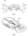
- FIG. 1is an exploded perspective view of an embodiment of a lens packaging system in accordance with the present invention
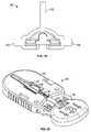
- FIG. 2is another exploded perspective view of the underside of an embodiment of a lens packaging system in accordance with the present invention
- FIG. 3is a perspective view of an embodiment of a tray of a lens packaging system in accordance with the present invention.
- FIG. 4is a perspective view of an embodiment of a lid of a lens packaging system in accordance with the present invention.
- FIG. 5is a perspective view of an embodiment of a cover of a lens packaging system in accordance with the present invention.
- FIG. 6is a perspective view of the underside of an embodiment of a lens packaging system in accordance with the present invention.
- FIG. 7is an alternate perspective view of the lens packaging system of FIG. 6 ;
- FIG. 8is a perspective view of an embodiment of a loading tool of a lens packaging system in accordance with the present invention.
- FIG. 9is a perspective view of an IOL loaded within a loading tool in accordance with the present invention.
- FIG. 10is a perspective view of an IOL and cartridge loaded within a loading tool in accordance with the present invention.
- FIG. 11is an alternate perspective view of the underside of the lens packaging system of FIG. 10 ;
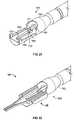
- FIGS. 12 and 13illustrate perspective views of an embodiment of a cartridge in accordance with the present invention
- FIG. 14illustrates a sectional view distal to the wings of the cartridge in accordance with the present invention
- FIG. 15illustrates a proximal end view of the loading end of a cartridge in accordance with the present invention
- FIG. 16illustrates an alternate embodiment of a lens packaging system with a lens and cartridge preloaded therein and the cover and lid removed in accordance with the present invention.
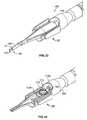
- FIGS. 17-19illustrate an alternate embodiment of a cartridge in accordance with the present invention
- FIG. 20illustrates an embodiment of a lens packaging system with a lens and cartridge preloaded therein and the cover and lid removed in accordance with the present invention
- FIG. 21illustrates an inserter in accordance with the present invention
- FIG. 22illustrates an insertion system in accordance with the present invention
- FIG. 23illustrates the insertion system shown in FIG. 22 with a pushrod extending distally from a cartridge
- FIG. 24illustrates the insertion system shown in FIG. 22 with an IOL draped over a saddle at the tip of a pushrod;
- FIG. 25illustrates an embodiment of a cartridge with an IOL positioned therein in accordance with the present invention
- FIG. 26illustrates an embodiment of a cartridge with an IOL advanced toward the distal end of the cartridge in accordance with the present invention.
- FIG. 27illustrates the insertion system shown in FIG. 22 with an IOL extending distally from the cartridge.
- a lens packaging system/lens loading system 10in accordance with embodiments of the present invention includes a tray 12 , a lid 14 , a cover 16 and a loading tool 18 .
- the tray 12is configured to hold and store a foldable IOL 20 and a cartridge 22 .
- the IOL 20 and cartridge 22are held within the tray 12 via the lid 14 , cover 16 and loading tool 18 .
- the tray 12also includes a lock (not shown) to secure the loading tool 18 during shipment and storage of the packaging system 10 and, thereby, prevent accidental activation of the loading tool 18 .
- the packaging system 10may be fabricated as a disposable, single-use component or a reusable, multi-use component.
- a variety of materialsmay be used to fabricate the tray 12 , lid 14 , cover 16 and loading tool 18 of the packaging system 10 .
- These materialsinclude, but are not limited to, plastics, metals (such as stainless steel, aluminum or titanium), ceramics and the like, including combinations thereof.
- the tray 12is fabricated from polypropylene, and the lid 14 and loading tool 18 are fabricated from polycarbonate.
- the tray 12in one embodiment of the packaging system 10 , includes a distal end 24 , a proximal end 26 , a half-oval shaped top surface 28 and a sidewall 30 .
- the distal end 24 of the tray 12is rounded or curved to conform to the curved portion of the half-oval shaped top surface 28 .
- the proximal end 26 of the tray 12is also slightly curved or rounded and arches in the same direction as the distal end 24 of the tray 12 .
- the proximal end 26 of the tray 12is configured to accommodate the loading tool 18 of the packaging system 10 , as described in further detail below.
- the distal and proximal ends 24 , 26 of the tray 12are arched in opposite directions. Furthermore, in certain embodiments, the distal and proximal ends 24 , 26 of the tray 12 are angled to form a portion of a square, rectangle, triangle, quadrilateral, regular and/or irregular-shaped form.
- the top surface 28 of the tray 12is generally planar or flat and includes one or more indentations and/or apertures 32 , 33 , 34 formed therein.
- the apertures 32are disposed to either side of the top surface 28 and guide elements or posts, for aligning the lid 14 and/or loading tool 18 of the packaging system 10 .
- the proximal-most apertures 33are formed as two round holes in the top surface 28 of the tray. These apertures or holes 33 are configured to accommodate the alignment pins of the lid 14 , as explained in further detail below.
- the center aperture 34is configured to accommodate a lens 20 and lens cartridge 22 , or similar lens holding and/or folding device.
- the center aperture 34is approximately cross-shaped and includes a wide transverse slot 36 that intersects a narrow, elongate longitudinal slot 38 extending approximately from the proximal end 26 to the distal end 24 of the tray.
- the center aperture 34further includes various chamfers and ridges within each slot 36 , 38 , which provide additional support and stability for the lens cartridge 22 .
- each side-slot 40Adjacent the center aperture 34 are two additional longitudinal side-slots 40 .
- Each side-slot 40is positioned on either side and in alignment with the wide transverse slot 36 of the center aperture 34 .
- the side-slots 40are approximately L-shaped and extend along the longitudinal axis near the side edges 42 of the tray 12 .
- the side-slots 40are designed to accommodate the guideposts of the cover 16 , as described in further detail below.
- a sidewall 44Integral with the top surface 28 of the tray 12 is a sidewall 44 .
- the sidewall 44extends along the perimeter of the top surface 28 and forms a hollow cavity beneath the top surface 28 of the tray 12 .
- an opening 46extends along a portion of the sidewall 44 located near the tray's proximal end 26 .
- the opening 46includes a first portion 48 and a second portion 50 , wherein the first portion 48 of the opening 46 extends along a transverse, proximal section of the tray's sidewall 44 .
- the second portion 50 of the opening 46forms a longitudinal slot that is continuous with the first portion 48 and extends in a distal direction along the top surface 28 of the tray 12 .
- the second portion 50 of the opening 46merges with the central aperture 34 of the top surface 28 .
- the opening 46is configured to accommodate the loading tool 18 of the packaging system 10 , as described in further detail below.
- the shape of the lid 14is nearly identical to the shape of the tray 12 .
- the sidewall 52 of the lid 14does not extend completely around the perimeter of the lid's top surface 54 but, rather, includes a generally rectangular-shaped gap or aperture 56 near the proximal end 58 of the lid 14 .
- each vertical edge 60 of the sidewall 52 that frames the gap or aperture 56further includes at least one notch 62 , which is continuous with the aperture 56 near the proximal end 58 of the lid 14 .
- the lid's aperture and notches 56 , 62which are in direct alignment with the longitudinal slot 46 of the tray 12 , are generally configured to accommodate the loading tool 18 when fully advanced during transfer of the IOL 20 into the cartridge 22 .
- the proximal end of the lid's top surface 54does not include apertures or indentations, as does the tray 12 .
- the underside of the lid 14near its proximal end, may include one or more alignment pins 35 . As explained above, these alignment pins 35 are configured to seat within the proximal-most apertures 33 of the tray 12 and, thereby, align and secure the lid 14 onto the tray 12 of the device 10 .
- a central window 64 and indentations or tabs 66are formed in the top surface 54 of the lid 14 and are generally aligned with the center aperture 34 of the tray 12 .
- the central window 64 and tabs 66allow portions of the cartridge 22 to be exposed, with the remaining portions of the cartridge 22 covered and secured by the lid 14 .
- the lid 14functions to secure the cartridge 22 within the packaging system 10 during storage and/or use of the system/device 10 .
- the lid 14 of the packaging system 10also includes one or more longitudinal side-slots 68 .
- the side-slots 68are positioned on either side of the indentations/tabs 66 and are designed to accommodate the guideposts of the cover 16 .
- it is instructive to first describe the cover 16making reference to FIGS. 1 , 2 , 5 , 6 and 7 .
- FIG. 5depicts an embodiment of the cover 16 as used in the packaging system 10 .
- the cover 16preferably includes a generally planar or flat body 70 and two guideposts 72 .
- the body 70 of the cover 16further includes a top surface 78 and a bottom surface (not visible) that are shaped similar to the top surfaces 28 , 54 of the tray 12 and lid 14 .
- the body 70is preferably configured in a half-oval shape that includes a rounded or curved distal end 80 and a relatively straight or linear proximal end 82 .
- the body 70 of the cover 16is sized to cover a substantial portion of the top surface 54 of the lid 14 and, in particular, at least a portion of the central window and indentations of the lid 14 .
- the guideposts or guide elements 72 of the cover 16may also be relatively planar or flat, but lie in vertical planes that are perpendicular to the plane of the cover's bottom surface.
- Each guidepost 72is configured approximately in the shape of a quarter-circle and includes a first or longitudinal straight edge 83 , a second or vertical straight edge 84 and a rounded edge 86 .
- the first straight edge 83 of each guidepost 72extends parallel to the bottom surface of the cover 16
- the second edge 84is preferably positioned at approximately a ninety-degree angle from the first straight edge near the proximal end 82 .
- a notch 85is formed in the portion of the guidepost 72 where the first and second edges 84 intersect, the area around the notch 85 forming a type of neck or stem region 87 .
- the stem region 87is configured to seat within the narrow portion of the L-shaped slot 40 of the tray 12 , as explained in further detail below.
- the remaining rounded edge 86 of the guidepost 72connects the first and second edges 84 of the guidepost 72 , thereby forming its generally quarter-circle shape.
- each guidepost 72is sized to fit within the longitudinal side-slots 40 , 68 of the tray 12 and lid 14 .
- the guideposts 72are generally parallel to each other and symmetrically positioned near the side edges of the cover 16 , which generally correspond to the side edges of the lid 12 and tray 14 .
- FIGS. 1 , 2 and 8there is a need for a packaging system 10 that enables a user to easily transfer an IOL 20 into a cartridge 22 without damaging the IOL 20 or compromising its sterility.
- the lens packaging system 10substantially eliminates these undesirable characteristics, it is instructive to particularly describe the loading tool 18 that reliably drives or transfers the IOL 20 into the cartridge 22 while maintaining IOL sterility. For this purpose, reference is made to FIGS. 1 , 2 and 8 .
- FIGS. 1 , 2 and 8illustrate one embodiment of the loading tool 18 , which includes a oval-shaped handle 92 in communication with a half-oval shaped slide 94 .
- the handle 92 of the loading tool 18includes a circular pushing surface 96 and a sidewall 98 that extends around the perimeter of the surface 96 .
- the sidewall 98provides additional structural support and gives added dimension to the handle 92 to enable a user to securely and controllably grip the loading tool 18 of the system.
- the half-oval shaped slide 94is connected to the handle 92 of the loading tool 18 via the sidewall 98 .
- the slide 94 of the loading tool 18includes a generally planar or flat body 100 having a top surface and a bottom surface that are shaped similar to the top surfaces 28 , 54 of the tray 12 and lid 14 .
- the slide 94 of the loading tool 18is configured in a half-oval shape that includes a generally rounded or curved distal end 102 , two side-edges 104 and a proximal end 106 that follows the outline-shape of a portion of the sidewall 98 .
- the slide 94is sized to fit through the opening 46 of the sidewall 44 and within the tray 12 of the packaging system 10 .
- one or more indentations 105are located along the side-edges 104 and near the proximal end of the planar body 100 of the loading tool 18 . These indentations 105 are configured to bypass the portion or section of the lid's sidewall 52 that surrounds or frames the lid's notches 62 . In particular, during storage, the indentations 105 of the loading tool 18 are positioned proximal to and outside of the notches 62 of the lid 14 . As such, the wider, non-indented section of the loading tool 18 is seated within the notches 62 during storage so that the lid 14 cannot be removed from the system or device 10 . However, when the loading tool 18 is actuated or advanced distally, the indentations 105 fall into alignment with the notches 62 , thereby allowing lid removal.
- each side-edge 104 of the slide 94further includes one or more detents 109 which are configured to interact with the detent-slots 111 of the tray 12 .
- Adjacent the detents 109is a groove or slot 108 that extends along a longitudinal length of the slide 94 .
- the grooves 108are configured to accommodate the guideposts 72 of the cover 16 when the loading tool 18 is in a fully retracted or non-actuated position, as shown in FIG. 6 , for example.
- grooves 108also allow sufficient inward movement of the side-edges of the loading tool 18 to enable the detents 109 to pop out of the detent-slots 111 of tray 12 and travel along the inside sidewall of the tray 12 during device activation.
- the detents 109 of the loading tool 18are seated within the detent-slots 111 of the tray 12 .
- the guideposts 72 of the cover 16are seated within the slots 68 , 40 , 108 of the lid 14 , tray 12 and loading tool 18 and, in particular, are aligned with the detents 109 and detent-slots 111 .
- the guideposts 72prevent the detents 109 from causing the side-edges of the loading tool 18 to bow inward along the grooves 108 and from becoming dislodged from the detent-slots 111 of the tray 12 .
- the guideposts 72 of the cover 16serve, in part, to secure the system 10 during shipping and storage by preventing lateral distal advancement of the loading tool 18 .
- the distal end 112 of the support member 110includes a beveled and/or curved front edge formed to securely contact a portion of the IOL's perimeter and aid in advancing the IOL 20 into the cartridge 22 .
- the distal end 112further includes a groove located in the top surface of the support member 110 to securely hold a first or trailing haptic 113 a of the IOL 20 .
- the guide member 114Distal to the support member 110 is a guide member 114 .
- the guide member 114includes a semi-flexible, U-shaped base 116 and a wedge-shaped holder 118 .
- the forked end of the U-shaped base 116extends longitudinally toward the proximal end 106 and is integrally formed with the body 100 of the push-rod 18 .
- the wedge-shaped holder 118Located along the distal end and perpendicular to the planar, U-shaped member 116 is the wedge-shaped holder 118 .
- the wedge-shaped holder 118includes a notched or grooved top surface 120 and a sloping front end 121 .
- the grooved top surface 120 of the guide member 114is configured to securely hold the second or leading haptic 113 b of the IOL.
- the support member 110 and guide member 114not only aid in advancing the IOL 20 into the cartridge 22 , but also in controlling the IOL's rotational movement so that the IOL 20 , and in particular the leading haptic 113 b of the IOL 20 , is correctly positioned within the cartridge 22 .
- the U-shaped base 116 of the guide member 114forms a central through-hole or window 122 in the body 100 of the loading tool 18 .
- the window 122enables a user of the device 10 to access a portion of the IOL 20 prior to IOL transfer into the cartridge 22 .
- a user of the packaging system 10may easily apply a lubricant, viscoelastic gel or viscoelastic surgical device (VSD) (not shown) to the IOL 20 .
- VSDviscoelastic surgical device
- a VSDis injected into the eye to help maintain the shape of ocular structures and as a lubricant/coating to minimize trauma from surgical instruments and implants.
- viscoelasticmay also be used with IOLs as a form of lubricant to aid in the passing of the IOL 20 into and through the cartridge 22 and to help prevent air bubbles from being delivered into the eye with the IOL 20 , which would obstruct the surgeon's view during the IOL insertion procedure.
- FIGS. 12 and 13illustrate one preferred embodiment of the cartridge 22 for delivering an intraocular lens into the eye of a subject.
- the cartridge 22includes an elongate tubular body 124 and two wings 126 longitudinally disposed to either side of the body 124 and formed along a proximal portion of the exterior sides of the body 124 .
- the elongate body 124is disposed along a longitudinal axis 127 and includes a distal end 128 , a proximal end 130 and a tapering, longitudinal lumen 132 that extends along the axial length of body 124 .
- the lumen 132comprises a load chamber 131 disposed at the proximal end 130 of the body 124 for receiving or loading the IOL 20 and an aperture 133 disposed at the distal end 128 of the body 124 for delivering the IOL 20 into the eye of a subject.
- the lumen 132 or inside profile of the cartridge 22is generally symmetrical about the longitudinal axis of the cartridge 22 and sized to accommodate the rod tip of the handpiece (not shown) during the insertion procedure.
- the aperture 133 and the cross-sectional shape of the lumen 132 near the aperture 133generally comprises an upper portion 132 a and a lower portion 132 b .
- the upper portion 132 a in cross-sectionis generally arcuate or dome shaped and has a width a, while the lower portion in cross-section is generally horizontally disposed and has a width b that is preferably greater than the width a.
- the bottom of lower portion 132 bis preferably generally flat, as illustrated in FIG. 14 , but may alternatively be arcuate in shape, for instance to increase or decrease the cross-sectional area of the lumen 132 at or near the aperture 133 .
- the center of the IOL 20is generally disposed in the upper portion 132 a , while portions of the edges of the IOL 20 are substantially disposed in the lower portion 132 b.
- the interior surface of the lumen 132also includes one or more ribs 134 that extend substantially along the longitudinal length of the body 124 .
- the triangular-shaped ribs 134may extend from the loading area or proximal end 130 to the discharge area or distal end 128 of the cartridge 22 .
- the ribs 134function, at least in part, to fold or compress the edges of the IOL in a controlled manner toward the outer edges of the interior of the cartridge 22 .
- the symmetry of the body 124allows for even or uniform application of a coating to the interior surface simply using a spray apparatus.
- the cross-sectional area of the distal end of the lumen 132is generally smaller than or reduced relative to the cross-sectional area of the proximal end of the lumen 132 , as a result of the cartridge's tapered lumen 132 .
- the taper of the lumen 132aids in compressing or folding the IOL 20 as the IOL 20 passes through the lumen 132 of the cartridge 32 and into the patient's eye, as described in further detail below.
- the interior surface or inside edges of the cartridge 22also may be configured to accommodate the shape of the IOL 20 .
- This featurenot only provides additional control during IOL transfer into the cartridge 22 , but allows more efficient use of space to compress and guide the IOL 20 to the distal end 128 of the cartridge 22 .
- the inside edges of the cartridge 22are configured to mimic the shape of the AMO OptiEdge® IOL. The reduced friction between the IOL 20 and the interior wall of the cartridge 22 results in less force being needed to deform or compress the IOL 20 as it is pushed/advanced to the distal end 128 of the cartridge 22 .
- a portion of the bottom surface 136 of the cartridge 22includes an opening 138 which allows the wedge-shaped holder 118 of the loading tool 18 to extend therethrough and support the leading haptic 113 b of the lens 20 during shipping and storage of the device 10 and loading of the IOL 20 into the cartridge 22 .
- the opening 138provides a means of guiding the leading haptic 113 b in a forward direction toward the distal tip of the cartridge 22 when the IOL 20 is advanced into the cartridge 22 .
- the opening 138 of the cartridge 22may also be configured to allow a portion of the rod-tip of a handpiece to contact and/or push the IOL 20 through and out of the cartridge 22 during the insertion procedure.
- the opening 138is preferably in the form of an elongated slot that is open at the proximal end 130 of the body 124 , as illustrated in FIG. 13 .
- the opening 138may have other shapes, lengths, or aspect ratios depending upon the particular design requirements of the IOL 20 , the cartridge 22 , the loading tool 18 , or the inserter and pushrod used to deliver the IOL 20 into the eye of a subject.
- each of the wings 126 formed along the exterior side near the proximal end of the cartridge 22include a rectangular-shaped connecting rib 142 and finger grip 144 .
- the connecting rib 142extends along the longitudinal length of the proximal end 130 of the cartridge 22 and connects the finger grip 144 to the body 124 of the cartridge 22 .
- Perpendicular to the connecting rib 142is the rectangular-shaped finger grip 144 .
- the finger grip 144is illustrated as being rectangular in shape, it is understood that the finger grip 144 of the cartridge 22 can be configured in various shapes, sizes and textures, which allow a user of the device 10 to securely grasp the cartridge 22 .
- the finger grip 144 , connecting rib 142 and a portion of the cartridge body 124form an exterior slot or groove 146 that is configured to mate with and snap into the distal end of a handpiece.
- the loading tool 18 and the cartridge 22are mounted into the tray 12 .
- the IOL 20is preferably placed onto the IOL support member 110 of the loading tool 18 and disposed for loading into the load chamber 131 .
- the lid 14 and the cover 16are preferably placed over the tray 12 in order to protect the IOL 20 and prevent premature loading of the IOL 20 into the load chamber 131 .
- a viscoelastic or other substancemay be applied to both the IOL 20 and cartridge 22 of the device 10 .
- the window 122 in the loading tool 18enables a user to apply viscoelastic to the IOL 20 .
- the opening 138 in the cartridge 22also enables a user of the device 10 to easily administer viscoelastic into the cartridge 22 .
- the viscoelasticlubricates the surfaces of the cartridge 22 and IOL 20 , thereby mitigating any tearing of the IOL 20 as it travels through the cartridge 22 and reducing the incidence of tissue trauma to the eye.
- FIGS. 17-19an alternate embodiment of the cartridge 22 is illustrated in which the finger grips 144 of the wings 126 have been removed and a holding handle 150 has been added to top, exterior surface near the proximal end 130 of the cartridge 22 .
- FIG. 20the cartridge 22 illustrated in FIG. 17 is shown mounted in the tray 12 along with the loading tool 18 and the IOL 20 .
- the cartridge 22is used in conjunction with a handpiece to deliver the IOL 20 into the eye of a subject.
- FIGS. 21-24illustrate a handpiece 140 which is configured to hold the cartridge 22 , preferably after the loading tool 18 has been used to mount the IOL 20 into longitudinal lumen 132 .
- an insertion system 160 for delivering the intraocular lens 20 into the eye of a subjectcomprises the cartridge 22 and an inserter 161 .
- the inserter 161comprises a handpiece 162 and a pushrod 164 with a tip 168 having a saddle 170 .
- the saddle 170preferably has a smaller diameter than the remainder of the pushrod 164 , such that a ledge 171 is formed between the saddle 170 and the remaining portions of the pushrod 164 , as illustrated in FIGS. 21 and 23 .
- the opening 138 on the bottom surface 136 of the cartridge 22is disposed to permit passage of at least a portion of the tip 168 when cartridge is placed onto the handpiece 162 from above the handpiece 162 .
- the handpiece 162further comprises a raised platform 172 disposed below pushrod 164 , the raised platform 172 being sized to fit within the opening 138 .
- the platform 172may be configured to fit tightly within the opening 138 , for instance, to aid in securely maintaining the cartridge 22 when attached to the handpiece 162 ; however, a tight fit between the opening 138 and the platform 172 is not essential.
- the insertion system 160further comprises at least a portion of the lens packaging system/lens loading system 10 for storing the IOL 20 and/or for placing the IOL 20 in the cartridge 22 .
- the system 160may include the tray 12 and the loading tool 18 .
- the system 160may include the lid 14 and the cover 16 , for instance, in order to protect the IOL 20 and prevent premature loading of the IOL 20 into the load chamber 131 .
- the IOL 20is preferable place inside the packaging system 10 prior to storage and/or shipment to a customer or user.
- at least portions of the system 10for example the tray 12 and the loading tool 18 , may be stored or shipped as separate parts. A practitioner may then use the portions of the packaging system 10 to load the IOL 20 inside the load chamber 133 of the cartridge 22 just prior to placing the IOL inside an eye using the handpiece 162 .
- the distal end of the handpiece 140includes two rails or side-edges 148 having slightly curved proximal and distal ends.
- the rails 148are sized and shaped to fit securely within the grooves 146 of the cartridge 22 , with the distal ends of the rails 148 having a greater curved depth than the proximal ends.
- the distal ends of the cartridge grooves 146are first slid into the curved distal ends of the rails 148 .
- the proximal ends of the grooves 146are then inserted downward and preferably snapped into the curved proximal ends of the rails 148 .
- the snap-fit between the grooves 146 and the rails 148keep the cartridge 22 securely within the handpiece 140 during the lens delivery procedure.
- the packaging system 10is typically supplied to an end-user or surgeon with a lens cartridge 22 and IOL 20 pre-loaded within the tray 12 .
- FIGS. 16 and 20illustrate embodiments of the packaging system as supplied to the end user with the cover 16 and lid 14 removed to clearly show the lens 20 and cartridge 22 within the device 10 .
- the packaging system 10may only include the IOL 20 , thereby allowing the user of the device 10 to supply the cartridge 22 .
- the tray 12 of the device 10Prior to use, the tray 12 of the device 10 is covered with the lid 14 and the loading tool 18 is a retracted or partially inserted position within the opening 46 of the tray 12 .
- the cover 16is secured to the lid 14 , tray 12 and loading tool 18 , via the guide elements 72 and slots 40 , 68 , 108 , to prevent inadvertent or unintentional activation of the system 10 .
- the guideposts or vertical members 72 of the cover 16block further distal advancement of the loading tool 18 , and its support member 110 , until the cover 16 is removed from the system 10 .
- the cover 16is removed to expose the top surface 54 of the lid 14 .
- the lid 14is fabricated from a clear material to allow the user of the device 10 to inspect the system 10 , particularly the lens cartridge 22 and IOL 20 , prior to use to ensure that none of the components are damaged. Removal of the cover 16 also exposes the central window 64 of the lid 14 and, thereby, a portion of the lens cartridge 22 . Viscoelastic fluid is applied to the cartridge 22 and/or the IOL 22 through the opening 138 and window 122 , respectively, prior to device activation.
- a usermay simply grasp the handle 92 of the loading tool 18 using, for example, his/her thumb and fore-finger, and push the loading tool 18 in a distal direction. Longitudinal sliding movement of the loading tool 18 causes the distal tip 112 of the support member 110 to push the IOL 20 along the longitudinal slot of the tray 12 and into the lumen 132 of the cartridge 22 .
- the lid 14 of the packaging system 10is then removed.
- the loading tool 18is proximally retracted to release the loaded cartridge 22 from the loading tool 18 and the loaded cartridge 22 is then removed from the packaging system.
- the usermay easily transfer the cartridge 22 with its loaded IOL 20 to the inserter 161 for delivery of the IOL 20 into a patient's eye.
- the packaging system 10may be used to simplify the removal and transfer of the IOL 20 to the IOL insertion system 160 .
- the packaging device 10enables a user to easily load an IOL 20 into a cartridge 22 without requiring the use of forceps.
- the configuration of the cartridge 22also allows a user to fold and/or compress the IOL 20 during IOL delivery into the eye without damaging the IOL 20 and/or compromising IOL sterility.
- the related methods of operationminimize and/or eliminate the potential of damaging the IOL 20 during unpackaging, folding, transfer and/or loading procedures.
- the device 10 and its method of useprovide repeatable and consistent loading (e.g., with respect to position and rotation) of the IOL 20 into the cartridge 22 .
- a method of inserting the IOL 20comprises providing the cartridge 22 and providing the handpiece 140 with the pushrod 164 having the saddle 170 in the tip 168 .
- the methodfurther comprises disposing the cartridge 22 above the handpiece 140 and attaching the cartridge 22 onto the handpiece 140 from above the handpiece 140 . While attaching the cartridge 22 , the method also includes disposing the tip 168 such that the opening 138 permits passage of at least a portion of the tip 168 , for instance, as illustrated in FIGS. 21 and 24 .
- the methodmay further comprises loading the IOL 20 in the cartridge 22 , for instance by using the loading tool 18 , as discussed above herein.
- the IOL 20is preferably placed in the cartridge 22 prior to attaching the cartridge 22 onto the handpiece 162 .
- the IOL 20is loaded into the load chamber such that at least a portion of at least one of the haptics 113 a , 113 b is disposed above at least a portion of the pushrod, as illustrated in FIG. 24 .
- the IOL 20is loaded into the load chamber 22 such at least a portion of an optic body 174 of the IOL 20 is disposed above or draped over the saddle 170 of the tip 168 , for instance, as illustrated in FIGS. 24 and 27 .
- the methodcomprises advancing the IOL 20 along the lumen 132 and into the eye of a subject at least in part by engaging an edge of the optic body 174 of the IOL 20 with the ledge 171 at the tip 168 of the pushrod 164 .
- the ledge 171may be used to help prevent the pushrod 164 from moving too far into the optic body 174 , thereby advantageously preventing the pushrod 164 from damaging the optic body 174 .
- the ledge 171may also be used to more evenly distribute the force produced by the pushrod 164 around the edge of the optic body 174 .
- the IOL 20is disposed in the load chamber 131 in a substantially flat and substantially unstressed state, as illustrated FIGS. 24 and 25 .
- the optic body 174 of the IOL 20is folded or squeezed such that the central portions of the IOL 20 fill the upper portion 132 b of the lumen 132 , as illustrated in FIG. 26 .
- the edges of the optic body 174 of the IOL 20largely are contained within the lower portion 132 a of the lumen, thereby advantageously allowing the orientation of the IOL 20 to be maintained as it advances down the lumen 132 and into the eye of the subject. In certain embodiments, as illustrated in FIG. 27 , this allows the IOL 20 to exit the aperture 133 of the lumen 132 in substantially the same orientation as it had when it was in the load chamber 131 .
Landscapes
- Health & Medical Sciences (AREA)
- Ophthalmology & Optometry (AREA)
- Cardiology (AREA)
- Oral & Maxillofacial Surgery (AREA)
- Transplantation (AREA)
- Engineering & Computer Science (AREA)
- Biomedical Technology (AREA)
- Heart & Thoracic Surgery (AREA)
- Vascular Medicine (AREA)
- Life Sciences & Earth Sciences (AREA)
- Animal Behavior & Ethology (AREA)
- General Health & Medical Sciences (AREA)
- Public Health (AREA)
- Veterinary Medicine (AREA)
- Prostheses (AREA)
Abstract
Description
Claims (5)
Priority Applications (4)
| Application Number | Priority Date | Filing Date | Title |
|---|---|---|---|
| US11/071,549US7458976B2 (en) | 2005-03-02 | 2005-03-02 | Devices and methods for storing, loading, and delivering an intraocular lens |
| US12/265,649US7867240B2 (en) | 2005-03-02 | 2008-11-05 | Devices and methods for storing, loading, and delivering an intraocular lens |
| US12/961,850US8048085B2 (en) | 2004-03-02 | 2010-12-07 | Devices and methods for storing, loading, and delivering an intraocular lens |
| US13/243,520US8506575B2 (en) | 2004-03-02 | 2011-09-23 | Devices and methods for storing, loading, and delivering an intraocular lens |
Applications Claiming Priority (1)
| Application Number | Priority Date | Filing Date | Title |
|---|---|---|---|
| US11/071,549US7458976B2 (en) | 2005-03-02 | 2005-03-02 | Devices and methods for storing, loading, and delivering an intraocular lens |
Related Child Applications (1)
| Application Number | Title | Priority Date | Filing Date |
|---|---|---|---|
| US12/265,649ContinuationUS7867240B2 (en) | 2004-03-02 | 2008-11-05 | Devices and methods for storing, loading, and delivering an intraocular lens |
Publications (2)
| Publication Number | Publication Date |
|---|---|
| US20060200167A1 US20060200167A1 (en) | 2006-09-07 |
| US7458976B2true US7458976B2 (en) | 2008-12-02 |
Family
ID=36945078
Family Applications (4)
| Application Number | Title | Priority Date | Filing Date |
|---|---|---|---|
| US11/071,549Active2026-03-06US7458976B2 (en) | 2004-03-02 | 2005-03-02 | Devices and methods for storing, loading, and delivering an intraocular lens |
| US12/265,649Expired - LifetimeUS7867240B2 (en) | 2004-03-02 | 2008-11-05 | Devices and methods for storing, loading, and delivering an intraocular lens |
| US12/961,850Expired - LifetimeUS8048085B2 (en) | 2004-03-02 | 2010-12-07 | Devices and methods for storing, loading, and delivering an intraocular lens |
| US13/243,520Expired - LifetimeUS8506575B2 (en) | 2004-03-02 | 2011-09-23 | Devices and methods for storing, loading, and delivering an intraocular lens |
Family Applications After (3)
| Application Number | Title | Priority Date | Filing Date |
|---|---|---|---|
| US12/265,649Expired - LifetimeUS7867240B2 (en) | 2004-03-02 | 2008-11-05 | Devices and methods for storing, loading, and delivering an intraocular lens |
| US12/961,850Expired - LifetimeUS8048085B2 (en) | 2004-03-02 | 2010-12-07 | Devices and methods for storing, loading, and delivering an intraocular lens |
| US13/243,520Expired - LifetimeUS8506575B2 (en) | 2004-03-02 | 2011-09-23 | Devices and methods for storing, loading, and delivering an intraocular lens |
Country Status (1)
| Country | Link |
|---|---|
| US (4) | US7458976B2 (en) |
Cited By (34)
| Publication number | Priority date | Publication date | Assignee | Title |
|---|---|---|---|---|
| US20090248031A1 (en)* | 2005-12-08 | 2009-10-01 | Hoya Corporation | Instrument for inserting intraocular lens |
| US20090270876A1 (en)* | 2008-04-28 | 2009-10-29 | Advanced Medical Optics, Inc. | Back loaded iol insertion cartridge |
| USD615651S1 (en)* | 2008-04-28 | 2010-05-11 | Abbott Medical Optics Inc. | Back loaded intraocular lens (IOL) cartridge |
| US20100211051A1 (en)* | 2007-10-16 | 2010-08-19 | Philip Douglas Weston | System and method for descemet's stripping automated endothelial keratoplasty (DSAEK) surgery |
| US8382769B2 (en) | 2008-06-17 | 2013-02-26 | Hoya Corporation | Intraocular lens insertion device |
| US8460311B2 (en) | 2004-12-27 | 2013-06-11 | Hoya Corporation | Intraocular lens implanting device |
| US8470032B2 (en) | 2008-09-04 | 2013-06-25 | Hoya Corporation | Intraocular lens insertion device |
| US8475528B2 (en) | 2007-05-30 | 2013-07-02 | Hoya Corporation | Intraocular lens insertion device |
| US8523877B2 (en) | 2005-02-24 | 2013-09-03 | Hoya Corporation | Intraocular lens inserting instrument |
| US8545512B2 (en) | 2005-01-26 | 2013-10-01 | Hoya Corporation | Intraocular lens insertion device |
| US8574239B2 (en) | 2005-09-28 | 2013-11-05 | Hoya Corporation | Intraocular lens insertion device |
| US8603103B2 (en) | 2009-01-07 | 2013-12-10 | Hoya Corporation | Intraocular lens insertion device |
| US8647382B2 (en) | 2010-06-10 | 2014-02-11 | Hoya Corporation | Ocular implant insertion apparatus and methods |
| US8702795B2 (en) | 2008-08-21 | 2014-04-22 | Hoya Corporation | Intraocular lens inserting device |
| US8747465B2 (en) | 2007-05-30 | 2014-06-10 | Hoya Corporation | Intraocular lens insertion device |
| US8998983B2 (en) | 2012-06-04 | 2015-04-07 | Altaviz, Llc | Intraocular lens inserters |
| US9114006B2 (en) | 2007-07-11 | 2015-08-25 | Hoya Corporation | Intraocular lens insertion device and method for controlling movement of the intraocular lens |
| US9155615B2 (en) | 2012-11-09 | 2015-10-13 | Bausch & Lomb Incorporated | Hingeless cartridge for use with an intraocular lens injector providing haptic control |
| US20150342730A1 (en)* | 2012-12-20 | 2015-12-03 | Humanoptics Ag | Intraocular lens storage system |
| US9326847B2 (en) | 2010-04-08 | 2016-05-03 | Hoya Corporation | Ocular implant insertion apparatus and methods |
| US9554894B2 (en) | 2008-06-05 | 2017-01-31 | Hoya Corporation | Intraocular lens insertion device and cartridge |
| USD789520S1 (en) | 2015-02-18 | 2017-06-13 | Icares Medicus, Inc. | Injector barrel and plunger |
| US9693895B2 (en) | 2012-06-12 | 2017-07-04 | Altaviz, Llc | Intraocular gas injector |
| US10010408B2 (en) | 2014-04-04 | 2018-07-03 | Alcon Pharmaceuticals, Ltd. | Intraocular lens inserter |
| US10172706B2 (en) | 2015-10-31 | 2019-01-08 | Novartis Ag | Intraocular lens inserter |
| US10799339B2 (en) | 2015-09-16 | 2020-10-13 | Hoya Corporation | Intraocular lens injector |
| US10849738B2 (en) | 2015-09-16 | 2020-12-01 | Hoya Corporation | Intraocular lens injector |
| US11000367B2 (en) | 2017-01-13 | 2021-05-11 | Alcon Inc. | Intraocular lens injector |
| US11033382B2 (en) | 2016-06-28 | 2021-06-15 | Hoya Corporation | Intraocular lens injector |
| USD940865S1 (en)* | 2016-08-15 | 2022-01-11 | Board Of Regents, The University Oftexas System | Allograft insertion device |
| US11224537B2 (en) | 2018-10-19 | 2022-01-18 | Alcon Inc. | Intraocular gas injector |
| US12076231B2 (en) | 2018-05-25 | 2024-09-03 | Hoya Corporation | Intraocular lens injector |
| US12257145B2 (en) | 2018-05-16 | 2025-03-25 | HOYA Medical Singapore Pte. Ltd. | Intraocular lens injector with container |
| US12414852B2 (en) | 2016-06-28 | 2025-09-16 | HOYA Medical Singapore Pte. Ltd. | Intraocular lens injector |
Families Citing this family (69)
| Publication number | Priority date | Publication date | Assignee | Title |
|---|---|---|---|---|
| US10835373B2 (en) | 2002-12-12 | 2020-11-17 | Alcon Inc. | Accommodating intraocular lenses and methods of use |
| US7217288B2 (en) | 2002-12-12 | 2007-05-15 | Powervision, Inc. | Accommodating intraocular lens having peripherally actuated deflectable surface and method |
| US8328869B2 (en) | 2002-12-12 | 2012-12-11 | Powervision, Inc. | Accommodating intraocular lenses and methods of use |
| US8361145B2 (en) | 2002-12-12 | 2013-01-29 | Powervision, Inc. | Accommodating intraocular lens system having circumferential haptic support and method |
| US8403941B2 (en)* | 2003-06-02 | 2013-03-26 | Abbott Medical Optics Inc. | Intraocular lens and cartridge packaging with lens-loading function |
| US9872763B2 (en) | 2004-10-22 | 2018-01-23 | Powervision, Inc. | Accommodating intraocular lenses |
| US8460375B2 (en)* | 2006-08-14 | 2013-06-11 | Novartis Ag | Lens delivery system |
| US9522061B2 (en) | 2007-02-15 | 2016-12-20 | Novartis Ag | Lens delivery system |
| US20080312661A1 (en)* | 2007-06-12 | 2008-12-18 | Downer David A | Lens Injector Lumen Tip for Wound Assisted Delivery |
| US8314927B2 (en)* | 2007-07-23 | 2012-11-20 | Powervision, Inc. | Systems and methods for testing intraocular lenses |
| US8956408B2 (en) | 2007-07-23 | 2015-02-17 | Powervision, Inc. | Lens delivery system |
| CN101795642B (en) | 2007-07-23 | 2013-11-27 | 力景公司 | Post-implant lens power modification |
| EP2671541B1 (en) | 2007-07-23 | 2019-04-17 | PowerVision, Inc. | Accommodating intraocular lenses |
| US8968396B2 (en) | 2007-07-23 | 2015-03-03 | Powervision, Inc. | Intraocular lens delivery systems and methods of use |
| US8668734B2 (en) | 2010-07-09 | 2014-03-11 | Powervision, Inc. | Intraocular lens delivery devices and methods of use |
| KR101264267B1 (en)* | 2008-02-07 | 2013-05-22 | 알콘, 인코퍼레이티드 | lens delivery system cartridge |
| US8808308B2 (en) | 2008-10-13 | 2014-08-19 | Alcon Research, Ltd. | Automated intraocular lens injector device |
| US8308736B2 (en) | 2008-10-13 | 2012-11-13 | Alcon Research, Ltd. | Automated intraocular lens injector device |
| US8801780B2 (en) | 2008-10-13 | 2014-08-12 | Alcon Research, Ltd. | Plunger tip coupling device for intraocular lens injector |
| GB2488546A (en)* | 2011-02-28 | 2012-09-05 | Philip Douglas Weston | Apparatus for preparing a cornea or lens implant |
| US20120226286A1 (en)* | 2008-10-16 | 2012-09-06 | Philip Douglas Weston | System and method for preparing a lenticular or corneal implant |
| US10299913B2 (en) | 2009-01-09 | 2019-05-28 | Powervision, Inc. | Accommodating intraocular lenses and methods of use |
| US9421092B2 (en)* | 2009-02-11 | 2016-08-23 | Alcon Research, Ltd. | Automated intraocular lens injector device |
| US11325533B2 (en) | 2009-04-23 | 2022-05-10 | Magna Mirrors Of America, Inc. | Frameless interior rearview mirror assembly |
| WO2010124064A1 (en) | 2009-04-23 | 2010-10-28 | Magna Mirrors Of America, Inc. | Mirror assembly for vehicle |
| EP2473138A4 (en)* | 2009-08-31 | 2017-08-16 | PowerVision, Inc. | Lens capsule size estimation |
| CN102648113B (en) | 2009-10-07 | 2015-05-27 | 麦格纳镜片美国有限公司 | Frameless interior rearview mirror assembly |
| US9346403B2 (en) | 2009-10-07 | 2016-05-24 | Magna Mirrors Of America, Inc. | Rearview mirror assembly |
| US11498486B2 (en) | 2009-10-07 | 2022-11-15 | Magna Mirrors Of America, Inc. | Vehicular exterior rearview mirror assembly |
| US10261648B2 (en) | 2009-10-07 | 2019-04-16 | Magna Mirrors Of America, Inc. | Exterior rearview mirror assembly |
| US12115913B2 (en) | 2010-02-10 | 2024-10-15 | Magna Mirrors Of America, Inc. | Vehicular exterior rearview mirror system |
| US9827913B2 (en) | 2010-02-10 | 2017-11-28 | Magna Mirrors Of America, Inc. | Exterior rearview mirror assembly |
| US9969334B2 (en) | 2010-02-10 | 2018-05-15 | Magna Mirrors Of America, Inc. | Exterior rearview mirror assembly |
| US8900298B2 (en) | 2010-02-23 | 2014-12-02 | Powervision, Inc. | Fluid for accommodating intraocular lenses |
| US8308799B2 (en) | 2010-04-20 | 2012-11-13 | Alcon Research, Ltd. | Modular intraocular lens injector device |
| US9301833B2 (en)* | 2012-04-20 | 2016-04-05 | Staar Surgical Company | Pre-loaded injector for use with intraocular lens |
| US8579969B2 (en) | 2010-07-25 | 2013-11-12 | Alcon Research, Ltd. | Dual mode automated intraocular lens injector device |
| JP2014505521A (en)* | 2010-12-20 | 2014-03-06 | ノバルティス アーゲー | Intraocular lens transfer case |
| EP2688515B1 (en) | 2011-03-24 | 2021-05-19 | Alcon Inc. | Intraocular lens loading systems and methods of use |
| US8690941B2 (en)* | 2011-10-04 | 2014-04-08 | Novartis Ag | Intraocular lens surgical system and method |
| US10433949B2 (en) | 2011-11-08 | 2019-10-08 | Powervision, Inc. | Accommodating intraocular lenses |
| DE102011056051A1 (en) | 2011-12-05 | 2013-06-06 | Conti Temic Microelectronic Gmbh | Method for evaluating image data of a vehicle camera taking into account information about rain |
| US8657835B2 (en) | 2012-01-27 | 2014-02-25 | Alcon Research, Ltd. | Automated intraocular lens injector device |
| EP2838471B1 (en)* | 2012-04-20 | 2016-03-02 | Vijay Gulati | Pre-loaded injector for use with intraocular lens |
| US9463089B2 (en) | 2012-05-21 | 2016-10-11 | Novartis Ag | Plunger system for intraocular lens surgery |
| JP6379421B2 (en)* | 2012-10-26 | 2018-08-29 | 参天製薬株式会社 | Intraocular lens injector |
| KR101379736B1 (en) | 2013-02-21 | 2014-04-01 | 주식회사 루시드코리아 | Intraocular lens keeping tray to take away it easily |
| EP3785668A1 (en) | 2013-03-15 | 2021-03-03 | Alcon Inc. | Intraocular lens storage and loading devices and methods of use |
| US9174578B2 (en) | 2013-04-22 | 2015-11-03 | Magna Mirrors Of America, Inc. | Interior rearview mirror assembly |
| US9676336B2 (en) | 2013-06-25 | 2017-06-13 | Magna Mirrors Of America, Inc. | Exterior rearview mirror assembly for vehicle |
| US9487142B2 (en) | 2013-06-25 | 2016-11-08 | Magna Mirrors Of America, Inc. | Rearview mirror assembly for vehicle |
| US9796334B2 (en) | 2014-06-13 | 2017-10-24 | Magna Mirrors Of America, Inc. | Exterior rearview mirror assembly for vehicle |
| AU2015315342B2 (en) | 2014-09-09 | 2020-02-20 | Staar Surgical Company | Ophthalmic implants with extended depth of field and enhanced distance visual acuity |
| US12127934B2 (en) | 2014-09-09 | 2024-10-29 | Staar Surgical Company | Method of Providing Modified Monovision to a Subject with a First Lens and a Second Lens |
| US10881504B2 (en) | 2016-03-09 | 2021-01-05 | Staar Surgical Company | Ophthalmic implants with extended depth of field and enhanced distance visual acuity |
| US10588780B2 (en) | 2015-03-04 | 2020-03-17 | Alcon Inc. | Intraocular lens injector |
| EP3307206B1 (en) | 2015-06-10 | 2023-09-20 | Alcon Inc. | Intraocular lens materials and components |
| WO2017079733A1 (en) | 2015-11-06 | 2017-05-11 | Powervision, Inc. | Accommodating intraocular lenses and methods of manufacturing |
| US10568735B2 (en) | 2017-01-13 | 2020-02-25 | Alcon Inc. | Intraocular lens injector |
| US20180200105A1 (en)* | 2017-01-14 | 2018-07-19 | Rxsight, Inc. | Intraocular lens inserter cartridge with a trailing haptic protection structure |
| CN119424042A (en)* | 2017-10-25 | 2025-02-14 | 爱博诺德(北京)医疗科技股份有限公司 | Introduction head, implantation device, method for loading intraocular lens and related components |
| EP3837571B1 (en) | 2018-08-17 | 2023-08-02 | Staar Surgical Company | Polymeric composition exhibiting nanogradient of refractive index |
| US11118010B2 (en) | 2019-04-24 | 2021-09-14 | Wuhan China Star Optoelectronics Semiconductor Display Technology Co., Ltd. | Polycarbonate, method for preparing thereof, and application thereof |
| WO2021032575A1 (en)* | 2019-08-16 | 2021-02-25 | Universität Zu Köln | Device for the preparation of a descemet's membrane-endothelium graft |
| US12246648B2 (en) | 2021-01-19 | 2025-03-11 | Magna Mirrors Of America, Inc. | Vehicular exterior rearview mirror assembly with locking feature |
| US12351108B2 (en) | 2021-07-09 | 2025-07-08 | Magna Mirrors Of America, Inc. | Vehicular exterior rearview mirror assembly with extendable and retractable mirror head |
| WO2023009664A1 (en)* | 2021-07-30 | 2023-02-02 | SpyGlass Pharma, Inc. | Systems to affix devices to intraocular lens assemblies and related methods |
| WO2023060017A1 (en) | 2021-10-04 | 2023-04-13 | Staar Surgical Company | Ophthalmic implants for correcting vision with a tunable optic, and methods of manufacture and use |
| US20230180918A1 (en)* | 2021-12-13 | 2023-06-15 | JJK Enterprises Inc. | Lift belt |
Citations (10)
| Publication number | Priority date | Publication date | Assignee | Title |
|---|---|---|---|---|
| US5123905A (en)* | 1991-06-07 | 1992-06-23 | Kelman Charles D | Intraocular lens injector |
| US5190552A (en)* | 1992-02-04 | 1993-03-02 | Kelman Charles D | Slotted tube injector for an intraocular lens |
| US5902307A (en)* | 1992-09-30 | 1999-05-11 | Starr Surgical Company, Inc. | Method of loading an intraocular lens into a lens injecting apparatus, and implanting the intraocular lens through a small incision made in an eye |
| US5947974A (en)* | 1997-12-09 | 1999-09-07 | Allergan | Folding device and method for an intraocular lens |
| US6056757A (en) | 1992-09-30 | 2000-05-02 | Staar Surgical Company, Inc. | Implantation device with deformable nozzle tip for implanting a deformable intraocular lens |
| US6447520B1 (en) | 2001-03-19 | 2002-09-10 | Advanced Medical Optics, Inc. | IOL insertion apparatus with IOL engagement structure and method for using same |
| EP1262154A1 (en) | 2001-06-01 | 2002-12-04 | Nidek Co., Ltd. | Intraocular lens injection instrument |
| US6540754B2 (en)* | 2001-01-26 | 2003-04-01 | Advanced Medical Optics, Inc. | Apparatus and method for multiply folding and inserting an intraocular lens in an eye |
| US6712848B1 (en) | 1992-09-30 | 2004-03-30 | Staar Surgical Company, Inc. | Deformable intraocular lens injecting apparatus with transverse hinged lens cartridge |
| US6733507B2 (en)* | 2002-04-12 | 2004-05-11 | Advanced Medical Optics, Inc. | Intraocular lens insertion apparatus |
Family Cites Families (23)
| Publication number | Priority date | Publication date | Assignee | Title |
|---|---|---|---|---|
| US5944725A (en) | 1996-09-26 | 1999-08-31 | Bausch & Lomb Surgical, Inc. | Method and apparatus for inserting a flexible membrane into an eye |
| US6371960B2 (en) | 1998-05-19 | 2002-04-16 | Bausch & Lomb Surgical, Inc. | Device for inserting a flexible intraocular lens |
| US6010510A (en) | 1998-06-02 | 2000-01-04 | Alcon Laboratories, Inc. | Plunger |
| FR2789890B1 (en)* | 1999-02-22 | 2002-01-18 | Lab Contactologie Appl Lca | DEVICE FOR INJECTING AN INTRAOCULAR LENS IN FLEXIBLE MATERIAL |
| SE9904338D0 (en) | 1999-11-30 | 1999-11-30 | Pharmacia & Upjohn Ab | Intraocular lens implants |
| GB0011507D0 (en) | 2000-05-13 | 2000-06-28 | Duckworth & Kent Ltd | Ophthalmic lens injectors |
| FR2820633B1 (en) | 2001-02-13 | 2003-08-15 | Biotech | INTRAOCULAR LENS INJECTION DEVICE AND METHOD |
| US20030060339A1 (en) | 2001-09-18 | 2003-03-27 | Sundaram Ravikumar | Soleus pump |
| JP4015934B2 (en) | 2002-04-18 | 2007-11-28 | 株式会社東芝 | Video coding method and apparatus |
| US7014641B2 (en) | 2002-05-08 | 2006-03-21 | Canon-Staar Co., Inc. | Insertion device for intraocular lens |
| US7156854B2 (en) | 2003-05-28 | 2007-01-02 | Alcon, Inc. | Lens delivery system |
| GB2405344A (en) | 2003-08-29 | 2005-03-02 | Fulcrum | Intraocular lens injector |
| WO2005070341A1 (en) | 2004-01-27 | 2005-08-04 | Hoya Corporation | Intraocular lens inserting device and cartridge thereof |
| ES2349954T3 (en) | 2004-04-22 | 2011-01-13 | Advanced Vision Science, Inc. | DEVICE FOR THE IMPLEMENTATION OF DEFORMABLE INTRAOCULAR LENSES. |
| BE1016692A3 (en) | 2005-07-25 | 2007-04-03 | Physiol | CARTRIDGE FOR A FLEXIBLE INTRAOCULAR LENS INJECTION DEVICE AND DEVICE PROVIDED WITH SUCH A CARTRIDGE. |
| EP2123239B1 (en) | 2006-05-18 | 2012-03-21 | STAAR Japan Inc. | Insertion device for intraocular lens |
| WO2008014260A1 (en) | 2006-07-25 | 2008-01-31 | Bausch & Lomb Incorporated | Intraocular lens injector plunger |
| US8114095B2 (en) | 2006-11-10 | 2012-02-14 | Bausch & Lomb Incorporated | Intraocular lens injection apparatus and method |
| US8333741B2 (en) | 2006-11-10 | 2012-12-18 | Bausch & Lomb Incorporated | Phacoemulsification cannula with improved purchase |
| JP5236638B2 (en) | 2007-05-30 | 2013-07-17 | Hoya株式会社 | Intraocular lens insertion device |
| US8475528B2 (en) | 2007-05-30 | 2013-07-02 | Hoya Corporation | Intraocular lens insertion device |
| US7754953B2 (en) | 2008-11-19 | 2010-07-13 | Pearl Musical Instrument Co. | Tension nut lock system for an instrument |
| WO2010102121A1 (en) | 2009-03-04 | 2010-09-10 | Anew Optics, Inc. | Injector for intraocular lens |
- 2005
- 2005-03-02USUS11/071,549patent/US7458976B2/enactiveActive
- 2008
- 2008-11-05USUS12/265,649patent/US7867240B2/ennot_activeExpired - Lifetime
- 2010
- 2010-12-07USUS12/961,850patent/US8048085B2/ennot_activeExpired - Lifetime
- 2011
- 2011-09-23USUS13/243,520patent/US8506575B2/ennot_activeExpired - Lifetime
Patent Citations (10)
| Publication number | Priority date | Publication date | Assignee | Title |
|---|---|---|---|---|
| US5123905A (en)* | 1991-06-07 | 1992-06-23 | Kelman Charles D | Intraocular lens injector |
| US5190552A (en)* | 1992-02-04 | 1993-03-02 | Kelman Charles D | Slotted tube injector for an intraocular lens |
| US5902307A (en)* | 1992-09-30 | 1999-05-11 | Starr Surgical Company, Inc. | Method of loading an intraocular lens into a lens injecting apparatus, and implanting the intraocular lens through a small incision made in an eye |
| US6056757A (en) | 1992-09-30 | 2000-05-02 | Staar Surgical Company, Inc. | Implantation device with deformable nozzle tip for implanting a deformable intraocular lens |
| US6712848B1 (en) | 1992-09-30 | 2004-03-30 | Staar Surgical Company, Inc. | Deformable intraocular lens injecting apparatus with transverse hinged lens cartridge |
| US5947974A (en)* | 1997-12-09 | 1999-09-07 | Allergan | Folding device and method for an intraocular lens |
| US6540754B2 (en)* | 2001-01-26 | 2003-04-01 | Advanced Medical Optics, Inc. | Apparatus and method for multiply folding and inserting an intraocular lens in an eye |
| US6447520B1 (en) | 2001-03-19 | 2002-09-10 | Advanced Medical Optics, Inc. | IOL insertion apparatus with IOL engagement structure and method for using same |
| EP1262154A1 (en) | 2001-06-01 | 2002-12-04 | Nidek Co., Ltd. | Intraocular lens injection instrument |
| US6733507B2 (en)* | 2002-04-12 | 2004-05-11 | Advanced Medical Optics, Inc. | Intraocular lens insertion apparatus |
Cited By (62)
| Publication number | Priority date | Publication date | Assignee | Title |
|---|---|---|---|---|
| US8460311B2 (en) | 2004-12-27 | 2013-06-11 | Hoya Corporation | Intraocular lens implanting device |
| US8545512B2 (en) | 2005-01-26 | 2013-10-01 | Hoya Corporation | Intraocular lens insertion device |
| US9220593B2 (en) | 2005-01-26 | 2015-12-29 | Hoya Corporation | Intraocular lens insertion device |
| US9364320B2 (en) | 2005-02-24 | 2016-06-14 | Hoya Corporation | Intraocular lens inserting instrument |
| US8523877B2 (en) | 2005-02-24 | 2013-09-03 | Hoya Corporation | Intraocular lens inserting instrument |
| US9114007B2 (en) | 2005-09-28 | 2015-08-25 | Hoya Corporation | Intraocular lens insertion device |
| US8574239B2 (en) | 2005-09-28 | 2013-11-05 | Hoya Corporation | Intraocular lens insertion device |
| US8968328B2 (en) | 2005-12-08 | 2015-03-03 | Hoya Corporation | Instrument for inserting intraocular lens |
| US20090248031A1 (en)* | 2005-12-08 | 2009-10-01 | Hoya Corporation | Instrument for inserting intraocular lens |
| US8523941B2 (en)* | 2005-12-08 | 2013-09-03 | Hoya Corporation | Instrument for inserting intraocular lens |
| US8475528B2 (en) | 2007-05-30 | 2013-07-02 | Hoya Corporation | Intraocular lens insertion device |
| US10390940B2 (en) | 2007-05-30 | 2019-08-27 | Hoya Corporation | Intraocular lens insertion device |
| US11938019B2 (en) | 2007-05-30 | 2024-03-26 | Hoya Corporation | Intraocular lens insertion device |
| US11617643B2 (en) | 2007-05-30 | 2023-04-04 | Hoya Corporation | Intraocular lens insertion device |
| US9289288B2 (en) | 2007-05-30 | 2016-03-22 | Hoya Corporation | Intraocular lens insertion device |
| US8535375B2 (en) | 2007-05-30 | 2013-09-17 | Hoya Corporation | Intraocular lens insertion device |
| US8747465B2 (en) | 2007-05-30 | 2014-06-10 | Hoya Corporation | Intraocular lens insertion device |
| US10405971B2 (en) | 2007-05-30 | 2019-09-10 | Hoya Corporation | Intraocular lens insertion device |
| US9907647B2 (en) | 2007-07-11 | 2018-03-06 | Hoya Corporation | Intraocular lens insertion device and method for controlling movement of the intraocular lens |
| US9114006B2 (en) | 2007-07-11 | 2015-08-25 | Hoya Corporation | Intraocular lens insertion device and method for controlling movement of the intraocular lens |
| US20100211051A1 (en)* | 2007-10-16 | 2010-08-19 | Philip Douglas Weston | System and method for descemet's stripping automated endothelial keratoplasty (DSAEK) surgery |
| US8702794B2 (en) | 2008-04-28 | 2014-04-22 | Abbott Medical Optics Inc. | Back loaded IOL insertion cartridge |
| USD615651S1 (en)* | 2008-04-28 | 2010-05-11 | Abbott Medical Optics Inc. | Back loaded intraocular lens (IOL) cartridge |
| US20090270876A1 (en)* | 2008-04-28 | 2009-10-29 | Advanced Medical Optics, Inc. | Back loaded iol insertion cartridge |
| US9283071B2 (en) | 2008-04-28 | 2016-03-15 | Abbott Medical Optics Inc. | Method of controlling IOL passage through a cartridge |
| US9788939B2 (en) | 2008-04-28 | 2017-10-17 | Abbott Medical Optics Inc. | Back loaded IOL insertion cartridge |
| US10517717B2 (en) | 2008-06-05 | 2019-12-31 | Hoya Corporation | Intraocular lens insertion device and cartridge |
| US9554894B2 (en) | 2008-06-05 | 2017-01-31 | Hoya Corporation | Intraocular lens insertion device and cartridge |
| US9186246B2 (en) | 2008-06-17 | 2015-11-17 | Hoya Corporation | Intraocular lens insertion devices and methods |
| US8382769B2 (en) | 2008-06-17 | 2013-02-26 | Hoya Corporation | Intraocular lens insertion device |
| US8702795B2 (en) | 2008-08-21 | 2014-04-22 | Hoya Corporation | Intraocular lens inserting device |
| US8470032B2 (en) | 2008-09-04 | 2013-06-25 | Hoya Corporation | Intraocular lens insertion device |
| US9655718B2 (en) | 2009-01-07 | 2017-05-23 | Hoya Corporation | Intraocular lens insertion device |
| US8603103B2 (en) | 2009-01-07 | 2013-12-10 | Hoya Corporation | Intraocular lens insertion device |
| US9877826B2 (en) | 2009-01-07 | 2018-01-30 | Hoya Corporation | Intraocular lens insertion device |
| US9901442B2 (en) | 2009-01-07 | 2018-02-27 | Hoya Corporation | Intraocular lens insertion device |
| US9326847B2 (en) | 2010-04-08 | 2016-05-03 | Hoya Corporation | Ocular implant insertion apparatus and methods |
| US9980811B2 (en) | 2010-06-10 | 2018-05-29 | Hoya Corporation | Ocular implant insertion apparatus and methods |
| US9572710B1 (en) | 2010-06-10 | 2017-02-21 | Hoya Corporation | Ocular implant insertion apparatus and methods |
| US8647382B2 (en) | 2010-06-10 | 2014-02-11 | Hoya Corporation | Ocular implant insertion apparatus and methods |
| US9314373B2 (en) | 2010-06-10 | 2016-04-19 | Hoya Corporation | Ocular implant insertion apparatus and methods |
| US10039668B2 (en) | 2010-06-10 | 2018-08-07 | Hoya Corporation | Ocular implant insertion apparatus and methods |
| US10188506B2 (en) | 2012-06-04 | 2019-01-29 | Alcon Pharmaceuticals, Ltd. | Intraocular lens inserter |
| US9724191B2 (en) | 2012-06-04 | 2017-08-08 | Alcon Pharmaceuticals, Ltd. | Intraocular lens inserter |
| US8998983B2 (en) | 2012-06-04 | 2015-04-07 | Altaviz, Llc | Intraocular lens inserters |
| US10434010B2 (en) | 2012-06-12 | 2019-10-08 | Alcon Pharmaceuticals Ltd. | Intraocular gas injector |
| US9693895B2 (en) | 2012-06-12 | 2017-07-04 | Altaviz, Llc | Intraocular gas injector |
| US9155615B2 (en) | 2012-11-09 | 2015-10-13 | Bausch & Lomb Incorporated | Hingeless cartridge for use with an intraocular lens injector providing haptic control |
| US20150342730A1 (en)* | 2012-12-20 | 2015-12-03 | Humanoptics Ag | Intraocular lens storage system |
| US9763775B2 (en)* | 2012-12-20 | 2017-09-19 | Humanoptics Ag | Intraocular lens storage system |
| US10010408B2 (en) | 2014-04-04 | 2018-07-03 | Alcon Pharmaceuticals, Ltd. | Intraocular lens inserter |
| USD789520S1 (en) | 2015-02-18 | 2017-06-13 | Icares Medicus, Inc. | Injector barrel and plunger |
| US10849738B2 (en) | 2015-09-16 | 2020-12-01 | Hoya Corporation | Intraocular lens injector |
| US10799339B2 (en) | 2015-09-16 | 2020-10-13 | Hoya Corporation | Intraocular lens injector |
| US10172706B2 (en) | 2015-10-31 | 2019-01-08 | Novartis Ag | Intraocular lens inserter |
| US11033382B2 (en) | 2016-06-28 | 2021-06-15 | Hoya Corporation | Intraocular lens injector |
| US12414852B2 (en) | 2016-06-28 | 2025-09-16 | HOYA Medical Singapore Pte. Ltd. | Intraocular lens injector |
| USD940865S1 (en)* | 2016-08-15 | 2022-01-11 | Board Of Regents, The University Oftexas System | Allograft insertion device |
| US11000367B2 (en) | 2017-01-13 | 2021-05-11 | Alcon Inc. | Intraocular lens injector |
| US12257145B2 (en) | 2018-05-16 | 2025-03-25 | HOYA Medical Singapore Pte. Ltd. | Intraocular lens injector with container |
| US12076231B2 (en) | 2018-05-25 | 2024-09-03 | Hoya Corporation | Intraocular lens injector |
| US11224537B2 (en) | 2018-10-19 | 2022-01-18 | Alcon Inc. | Intraocular gas injector |
Also Published As
| Publication number | Publication date |
|---|---|
| US8506575B2 (en) | 2013-08-13 |
| US20110098716A1 (en) | 2011-04-28 |
| US7867240B2 (en) | 2011-01-11 |
| US20120016375A1 (en) | 2012-01-19 |
| US8048085B2 (en) | 2011-11-01 |
| US20090062811A1 (en) | 2009-03-05 |
| US20060200167A1 (en) | 2006-09-07 |
Similar Documents
| Publication | Publication Date | Title |
|---|---|---|
| US7458976B2 (en) | Devices and methods for storing, loading, and delivering an intraocular lens | |
| CA2557967C (en) | Devices and methods for storing, loading, and delivering an intraocular lens | |
| US8475527B2 (en) | Intraocular lens and cartridge packaging with lens-loading function | |
| US9339374B2 (en) | Intraocular lens insertion apparatus and lens case | |
| US8562674B2 (en) | Front loading IOL insertion apparatus and method of using | |
| US20080147082A1 (en) | Injector apparatus for use with intraocular lenses and methods of use | |
| US20080147080A1 (en) | Injector apparatus for use with intraocular lenses and methods of use | |
| AU2012202321B2 (en) | Devices and methods for storing, loading, and delivering an intraocular lens | |
| AU2011203121B2 (en) | Intraocular lens and cartridge packaging with lens-loading function |
Legal Events
| Date | Code | Title | Description |
|---|---|---|---|
| AS | Assignment | Owner name:ADVANCED MEDICAL OPTICS, INC., CALIFORNIA Free format text:ASSIGNMENT OF ASSIGNORS INTEREST;ASSIGNORS:PETERSON, ROD T.;OTT, ROBERT D.;COLE, MARK S.;REEL/FRAME:018089/0138;SIGNING DATES FROM 20060803 TO 20060810 | |
| AS | Assignment | Owner name:BANK OF AMERICA, N.A., AS ADMINISTRATIVE AGENT,NOR Free format text:INTELLECTUAL PROPERTY SECURITY AGREEMENT;ASSIGNOR:ADVANCED MEDICAL OPTICS, INC.;REEL/FRAME:019501/0069 Effective date:20070402 Owner name:BANK OF AMERICA, N.A., AS ADMINISTRATIVE AGENT, NORTH CAROLINA Free format text:INTELLECTUAL PROPERTY SECURITY AGREEMENT;ASSIGNOR:ADVANCED MEDICAL OPTICS, INC.;REEL/FRAME:019501/0069 Effective date:20070402 Owner name:BANK OF AMERICA, N.A., AS ADMINISTRATIVE AGENT, NO Free format text:INTELLECTUAL PROPERTY SECURITY AGREEMENT;ASSIGNOR:ADVANCED MEDICAL OPTICS, INC.;REEL/FRAME:019501/0069 Effective date:20070402 | |
| STCF | Information on status: patent grant | Free format text:PATENTED CASE | |
| AS | Assignment | Owner name:ADVANCED MEDICAL OPTICS, INC., CALIFORNIA Free format text:RELEASE BY SECURED PARTY;ASSIGNOR:BANK OF AMERICA, N.A. AS ADMINISTRATIVE AGENT;REEL/FRAME:022320/0427 Effective date:20090225 Owner name:ADVANCED MEDICAL OPTICS, INC.,CALIFORNIA Free format text:RELEASE BY SECURED PARTY;ASSIGNOR:BANK OF AMERICA, N.A. AS ADMINISTRATIVE AGENT;REEL/FRAME:022320/0427 Effective date:20090225 | |
| AS | Assignment | Owner name:ABBOTT MEDICAL OPTICS INC., CALIFORNIA Free format text:MERGER;ASSIGNOR:ADVANCED MEDICAL OPTICS, INC.;REEL/FRAME:023234/0277 Effective date:20090226 Owner name:ABBOTT MEDICAL OPTICS INC.,CALIFORNIA Free format text:MERGER;ASSIGNOR:ADVANCED MEDICAL OPTICS, INC.;REEL/FRAME:023234/0277 Effective date:20090226 | |
| FPAY | Fee payment | Year of fee payment:4 | |
| FPAY | Fee payment | Year of fee payment:8 | |
| AS | Assignment | Owner name:JOHNSON & JOHNSON SURGICAL VISION, INC., CALIFORNI Free format text:CHANGE OF NAME;ASSIGNOR:ABBOTT MEDICAL OPTICS INC.;REEL/FRAME:047150/0976 Effective date:20180209 | |
| MAFP | Maintenance fee payment | Free format text:PAYMENT OF MAINTENANCE FEE, 12TH YEAR, LARGE ENTITY (ORIGINAL EVENT CODE: M1553); ENTITY STATUS OF PATENT OWNER: LARGE ENTITY Year of fee payment:12 |