US7458967B2 - Endovascular treatment apparatus and method - Google Patents
Endovascular treatment apparatus and methodDownload PDFInfo
- Publication number
- US7458967B2 US7458967B2US10/836,084US83608404AUS7458967B2US 7458967 B2US7458967 B2US 7458967B2US 83608404 AUS83608404 AUS 83608404AUS 7458967 B2US7458967 B2US 7458967B2
- Authority
- US
- United States
- Prior art keywords
- sheath
- tip
- thermal treatment
- delivery device
- treatment delivery
- Prior art date
- Legal status (The legal status is an assumption and is not a legal conclusion. Google has not performed a legal analysis and makes no representation as to the accuracy of the status listed.)
- Expired - Fee Related, expires
Links
- 238000000034methodMethods0.000titledescription38
- 238000012276Endovascular treatmentMethods0.000titledescription2
- 238000002604ultrasonographyMethods0.000claimsabstractdescription24
- 230000001965increasing effectEffects0.000claimsabstractdescription23
- 230000002787reinforcementEffects0.000claimsabstractdescription22
- 238000007669thermal treatmentMethods0.000claimsabstractdescription20
- 210000004204blood vesselAnatomy0.000claimsabstractdescription4
- 239000013307optical fiberSubstances0.000claimsdescription29
- 239000000463materialSubstances0.000claimsdescription17
- 230000000007visual effectEffects0.000claimsdescription15
- 239000004005microsphereSubstances0.000claimsdescription4
- 229920000642polymerPolymers0.000claimsdescription3
- 229910052751metalInorganic materials0.000claims2
- 239000007769metal materialSubstances0.000claims1
- 238000003780insertionMethods0.000abstractdescription26
- 230000037431insertionEffects0.000abstractdescription26
- 239000000835fiberSubstances0.000abstractdescription24
- 238000002347injectionMethods0.000abstractdescription23
- 239000007924injectionSubstances0.000abstractdescription23
- 230000006870functionEffects0.000abstractdescription8
- 210000003462veinAnatomy0.000description67
- 239000012530fluidSubstances0.000description19
- 238000003384imaging methodMethods0.000description16
- 238000011282treatmentMethods0.000description13
- 239000008280bloodSubstances0.000description11
- 210000004369bloodAnatomy0.000description11
- 238000013532laser treatmentMethods0.000description11
- 238000010992refluxMethods0.000description11
- 210000001519tissueAnatomy0.000description9
- 230000003014reinforcing effectEffects0.000description8
- 244000208734Pisonia aculeataSpecies0.000description7
- 230000006378damageEffects0.000description6
- 239000000945fillerSubstances0.000description6
- 238000005259measurementMethods0.000description6
- 230000036961partial effectEffects0.000description6
- 201000002282venous insufficiencyDiseases0.000description6
- 208000027418Wounds and injuryDiseases0.000description5
- 230000004888barrier functionEffects0.000description5
- 206010002091AnaesthesiaDiseases0.000description4
- NNJVILVZKWQKPM-UHFFFAOYSA-NLidocaineChemical compoundCCN(CC)CC(=O)NC1=C(C)C=CC=C1CNNJVILVZKWQKPM-UHFFFAOYSA-N0.000description4
- 206010052428WoundDiseases0.000description4
- 230000037005anaesthesiaEffects0.000description4
- TZCXTZWJZNENPQ-UHFFFAOYSA-Lbarium sulfateChemical compound[Ba+2].[O-]S([O-])(=O)=OTZCXTZWJZNENPQ-UHFFFAOYSA-L0.000description4
- 230000008901benefitEffects0.000description4
- 229960004194lidocaineDrugs0.000description4
- 238000002360preparation methodMethods0.000description4
- 206010046996Varicose veinDiseases0.000description3
- 239000003086colorantSubstances0.000description3
- 208000037265diseases, disorders, signs and symptomsDiseases0.000description3
- 239000000523sampleSubstances0.000description3
- 210000003752saphenous veinAnatomy0.000description3
- 230000007704transitionEffects0.000description3
- 238000012285ultrasound imagingMethods0.000description3
- FAPWRFPIFSIZLT-UHFFFAOYSA-MSodium chlorideChemical compound[Na+].[Cl-]FAPWRFPIFSIZLT-UHFFFAOYSA-M0.000description2
- 230000004913activationEffects0.000description2
- 230000008859changeEffects0.000description2
- 238000013461designMethods0.000description2
- 239000013536elastomeric materialSubstances0.000description2
- 238000002594fluoroscopyMethods0.000description2
- 239000003193general anesthetic agentSubstances0.000description2
- 238000001802infusionMethods0.000description2
- 230000014759maintenance of locationEffects0.000description2
- 230000007246mechanismEffects0.000description2
- 239000000203mixtureSubstances0.000description2
- 230000001681protective effectEffects0.000description2
- 239000011780sodium chlorideSubstances0.000description2
- 230000000699topical effectEffects0.000description2
- WFKWXMTUELFFGS-UHFFFAOYSA-NtungstenChemical compound[W]WFKWXMTUELFFGS-UHFFFAOYSA-N0.000description2
- 229910052721tungstenInorganic materials0.000description2
- 239000010937tungstenSubstances0.000description2
- 208000027185varicose diseaseDiseases0.000description2
- 206010051055Deep vein thrombosisDiseases0.000description1
- JOYRKODLDBILNP-UHFFFAOYSA-NEthyl urethaneChemical compoundCCOC(N)=OJOYRKODLDBILNP-UHFFFAOYSA-N0.000description1
- 208000032843HemorrhageDiseases0.000description1
- 208000012266Needlestick injuryDiseases0.000description1
- 239000004677NylonSubstances0.000description1
- 239000004698PolyethyleneSubstances0.000description1
- 206010048591Post thrombotic syndromeDiseases0.000description1
- 208000003251PruritusDiseases0.000description1
- 208000010378Pulmonary EmbolismDiseases0.000description1
- 239000004809TeflonSubstances0.000description1
- 229920006362Teflon®Polymers0.000description1
- 208000025865UlcerDiseases0.000description1
- 206010047249Venous thrombosisDiseases0.000description1
- 206010068149Vessel perforationDiseases0.000description1
- 238000002679ablationMethods0.000description1
- 230000009471actionEffects0.000description1
- 239000002390adhesive tapeSubstances0.000description1
- 230000002411adverseEffects0.000description1
- 230000003444anaesthetic effectEffects0.000description1
- 208000034158bleedingDiseases0.000description1
- 230000000740bleeding effectEffects0.000description1
- 230000000903blocking effectEffects0.000description1
- 230000017531blood circulationEffects0.000description1
- 238000010276constructionMethods0.000description1
- 239000002537cosmeticSubstances0.000description1
- 230000003247decreasing effectEffects0.000description1
- 239000003814drugSubstances0.000description1
- 229940079593drugDrugs0.000description1
- 230000009977dual effectEffects0.000description1
- 238000002592echocardiographyMethods0.000description1
- 230000002708enhancing effectEffects0.000description1
- 210000003191femoral veinAnatomy0.000description1
- 125000001153fluoro groupChemical groupF*0.000description1
- 230000023597hemostasisEffects0.000description1
- 230000003116impacting effectEffects0.000description1
- 208000014674injuryDiseases0.000description1
- 230000007803itchingEffects0.000description1
- 208000005592lipodermatosclerosisDiseases0.000description1
- 210000003141lower extremityAnatomy0.000description1
- 238000004519manufacturing processMethods0.000description1
- 239000003550markerSubstances0.000description1
- 230000013011matingEffects0.000description1
- 238000012986modificationMethods0.000description1
- 230000004048modificationEffects0.000description1
- 238000012544monitoring processMethods0.000description1
- 229920005615natural polymerPolymers0.000description1
- 230000017074necrotic cell deathEffects0.000description1
- 210000005036nerveAnatomy0.000description1
- 210000000944nerve tissueAnatomy0.000description1
- HLXZNVUGXRDIFK-UHFFFAOYSA-Nnickel titaniumChemical compound[Ti].[Ti].[Ti].[Ti].[Ti].[Ti].[Ti].[Ti].[Ti].[Ti].[Ti].[Ni].[Ni].[Ni].[Ni].[Ni].[Ni].[Ni].[Ni].[Ni].[Ni].[Ni].[Ni].[Ni].[Ni]HLXZNVUGXRDIFK-UHFFFAOYSA-N0.000description1
- 229910001000nickel titaniumInorganic materials0.000description1
- 229920001778nylonPolymers0.000description1
- 210000000056organAnatomy0.000description1
- 230000036407painEffects0.000description1
- 230000000149penetrating effectEffects0.000description1
- 208000001297phlebitisDiseases0.000description1
- -1polyethylenePolymers0.000description1
- 229920000573polyethylenePolymers0.000description1
- 239000002861polymer materialSubstances0.000description1
- 229920001296polysiloxanePolymers0.000description1
- 230000008569processEffects0.000description1
- 230000002829reductive effectEffects0.000description1
- 230000004044responseEffects0.000description1
- 210000003491skinAnatomy0.000description1
- 239000007779soft materialSubstances0.000description1
- 239000000243solutionSubstances0.000description1
- 229910001220stainless steelInorganic materials0.000description1
- 239000010935stainless steelSubstances0.000description1
- 230000008961swellingEffects0.000description1
- 208000024891symptomDiseases0.000description1
- 238000002560therapeutic procedureMethods0.000description1
- 230000036269ulcerationEffects0.000description1
- 210000005166vasculatureAnatomy0.000description1
- 238000012800visualizationMethods0.000description1
Images


Classifications
- A—HUMAN NECESSITIES
- A61—MEDICAL OR VETERINARY SCIENCE; HYGIENE
- A61B—DIAGNOSIS; SURGERY; IDENTIFICATION
- A61B18/00—Surgical instruments, devices or methods for transferring non-mechanical forms of energy to or from the body
- A61B18/18—Surgical instruments, devices or methods for transferring non-mechanical forms of energy to or from the body by applying electromagnetic radiation, e.g. microwaves
- A61B18/20—Surgical instruments, devices or methods for transferring non-mechanical forms of energy to or from the body by applying electromagnetic radiation, e.g. microwaves using laser
- A61B18/22—Surgical instruments, devices or methods for transferring non-mechanical forms of energy to or from the body by applying electromagnetic radiation, e.g. microwaves using laser the beam being directed along or through a flexible conduit, e.g. an optical fibre; Couplings or hand-pieces therefor
- A61B18/24—Surgical instruments, devices or methods for transferring non-mechanical forms of energy to or from the body by applying electromagnetic radiation, e.g. microwaves using laser the beam being directed along or through a flexible conduit, e.g. an optical fibre; Couplings or hand-pieces therefor with a catheter
- A—HUMAN NECESSITIES
- A61—MEDICAL OR VETERINARY SCIENCE; HYGIENE
- A61B—DIAGNOSIS; SURGERY; IDENTIFICATION
- A61B90/00—Instruments, implements or accessories specially adapted for surgery or diagnosis and not covered by any of the groups A61B1/00 - A61B50/00, e.g. for luxation treatment or for protecting wound edges
- A61B90/03—Automatic limiting or abutting means, e.g. for safety
- A61B2090/033—Abutting means, stops, e.g. abutting on tissue or skin
- A61B2090/036—Abutting means, stops, e.g. abutting on tissue or skin abutting on tissue or skin
- A—HUMAN NECESSITIES
- A61—MEDICAL OR VETERINARY SCIENCE; HYGIENE
- A61B—DIAGNOSIS; SURGERY; IDENTIFICATION
- A61B90/00—Instruments, implements or accessories specially adapted for surgery or diagnosis and not covered by any of the groups A61B1/00 - A61B50/00, e.g. for luxation treatment or for protecting wound edges
- A61B90/39—Markers, e.g. radio-opaque or breast lesions markers
Definitions
- the present inventionrelates to a medical device apparatus and method for treatment of blood vessels. More particularly, the present invention relates to an endovascular sheath apparatus and method for minimally invasive treatment of venous reflux disease.
- Veinscan be broadly divided into three categories: the deep veins, which are the primary conduit for blood return to the heart; the superficial veins, which parallel the deep veins and function as a channel for blood passing from superficial structures to the deep system; and topical or cutaneous veins, which carry blood from the end organs (e.g., skin) to the superficial system.
- Veinsare thin-walled and contain one-way valves that control blood flow. Normally, the valves open to allow blood to flow into the deep veins and close to prevent back-flow into the superficial veins. When the valves are malfunctioning or only partially functioning, however, they no longer prevent the back-flow of blood into the superficial veins. This condition is called reflux. As a result of reflux, venous pressure builds within the superficial system. This pressure is transmitted to topical veins, which, because the veins are thin walled and not able to withstand the increased pressure, become dilated, tortuous or engorged.
- venous reflux in the lower extremitiesis one of the most common medical conditions of the adult population. It is estimated that venous reflux disease affects approximately 25% of adult females and 10% of males. Symptoms of reflux include varicose veins and other cosmetic deformities, as well as aching, itching, and swelling of the legs. If left untreated, venous reflux may cause severe medical complications such as bleeding, phlebitis, ulcerations, thrombi and lipodermatosclerosis.
- Endovascular thermal therapyis a relatively new treatment technique for venous reflux diseases.
- thermal energy generated by laser, radio or microwave frequenciesis delivered to the inner vein wall causing vessel ablation or occlusion.
- a catheter, fiber or other delivery systemis percutaneously inserted into the lumen of the diseased vein.
- Thermal energyis delivered from the distal end of the delivery system as the device is slowly withdrawn through the vein.
- the procedurebegins with an introducer sheath being placed into the main superficial vein, called the great saphenous vein, at a distal location and advanced to within a few centimeters of the point at which the great saphenous vein enters the deep vein system, (the sapheno-femoral junction).
- a physicianwill measure the distance from the insertion or access site to the sapheno-femoral junction on the surface of the patient's skin. This measurement is then transferred to the sheath using tape, a marker or some other visual indicator to identify the insertion distance on the sheath shaft.
- Other superficial veinsmay be accessed depending on the origin of reflux.
- the sheathis placed using either ultrasonic guidance or fluoroscopic imaging.
- the physicianinserts the sheath into the vein using the visual mark on the sheath as an approximate insertion distance indicator.
- Ultrasonic or fluoroscopic imagingis then used to guide final placement of the tip relative to the junction.
- Positioning of the sheath tip relative to the sapheno-femoral junction or other reflux pointis critical to the procedure because the sheath tip position is used to confirm correct positioning of the fiber when it is inserted and advanced.
- Current art sheath tipsare often difficult to clearly visualize under either ultrasonic guidance or fluoroscopic imaging.
- a flexible optical fiberis inserted into the lumen of the sheath and advanced until the fiber tip is near the sheath tip but still protected within the sheath lumen.
- the fiberincludes a red aiming beam at the tip that is used to visualize the location of the fiber tip within the vessel lumen as it is advanced to the sapheno-femoral junction through the properly positioned sheath lumen. When activated, the aiming beam appears as a red glowing light visible through the skin surface.
- the sheath materialoften blocks the red aiming beam from being clearly visible on the skin surface as the fiber is advanced through the sheath.
- tumescent anesthesiaPrior to the application of thermal energy, tumescent anesthesia is injected along the entire length of the vein into space between the vein and the surrounding perivenous tissue. A mixture of saline and 0.1-0.5% lidocaine or other similar anesthetic agent is typically used. Tumescent anesthesia serves several functions.
- the fluidanatomically isolates the vein, creating a barrier to protect the tissue and nerves from the thermal energy. Specifically, the fluid provides a heat sink to prevent thermal injury to adjacent non-target tissues, nerves and the skin surface. Extrinsic pressure from the fluid also compresses the vessel, reducing the vein diameter, minimizing the volume of the vein, and maximizing the heat affect to the vein walls. Finally, the lidocaine mixture, with its anesthetic characteristics, reduces patient pain during the procedure.
- the tumescent injectionsare typically administered every few centimeters along the entire length of the vein under ultrasonic guidance. Ultrasound is used to visualize the vein, confirm proper location of the needle tip in the perivenous space, and to determine correct injection volumes. After the user has confirmed that the needle tip is correctly positioned between the vein and perivenous tissue through ultrasonic imaging, the tumescent fluid is slowly injected. Again, visualization of the target perivenous space is often difficult, and the user may inadvertently puncture the sheath wall with the needle tip during placement. The delicate fiber may also be damaged by incorrect placement of the needle.
- thermal energycan be applied to the vein.
- a laser generatoris activated causing energy to be emitted from the distal end of the optical fiber into the vessel.
- the energyreacts with the blood remaining in the vessel and causes heat, which damages the vein wall which, in turn, causes cell necrosis and eventual vein collapse.
- the sheath and fiberare slowly withdrawn as a single unit until the entire diseased segment of the vessel has been treated.
- sheaths for endovascular laser treatment of refluxhave several drawbacks.
- One problemis the difficulty in visualizing the sheath and particularly the tip as it is positioned just proximal to the sapheno-femoral junction.
- these same sheathsare not optimized for use with ultrasonic imaging modalities.
- the visibility of the tip under either fluoro or ultrasoundis very important when placing the tip relative to the sapheno-femoral junction. Incorrect placement may result in either incomplete occlusion of the vein or non-targeted thermal energy delivery to the femoral vein, which may result in deep vein thrombosis and its associated complications including pulmonary embolism.
- Another possible complication of a misplaced deviceis possible vessel perforation.
- Sheaths that are sold with endovascular laser treatment kitsdo not contain any shaft reinforcement to increase torquability, durability and kink resistance during insertion and placement within the vein.
- a reinforced sheath shaftis also desirable to provide a durable, protective barrier to the delicate fiber during tumescent injections, which are administered along the length of the vessel being treated.
- the sheathshould be designed to provide easy visual identification of the sheath location for precise positioning relative to the sapheno-femoral junction or other vessel target. Specifically, the sheath tip should be easily visible under either ultrasound or fluoroscopic imaging. The sheath should not block or decrease visibility of the aiming beam during fiber insertion through the sheath. The sheath should also be durable and resistant to needle punctures. The sheath should also be constructed to optimize torquability and kink-resistance during insertion and withdrawal. The device should also provide an easy, simple way for the physician to approximate insertion length and assess pullback rate during the procedure. In addition, the device should be easy and inexpensive to use.
- an endovascular sheath devicefor use with a thermal treatment apparatus.
- the sheath deviceincludes a longitudinal tube which is designed to receive a thermal treatment device and is designed to be inserted into a blood vessel.
- An ultrasonically visible reinforcement elementis disposed along a wall of the longitudinal tube.
- the reinforcement elementsuch as a braided wire provides several functions including increased visibility under ultrasound, clearer identification of sheath tip, and increased durability to protect the fiber from needle punctured during tumescent injections into the perivenous space.
- the wire reinforcementalso increases shaft torquability and kink resistance during sheath insertion and withdrawal.
- the longitudinal tubeincludes a radiopaque tip at its distal end which is fluoroscopically visible.
- the tipmay include a radiopaque filler such as Tungsten or Barium Sulfate for increased visibility under fluoroscopic imaging.
- the radiopaque filleris generally non-translucent, the radiopaque tip can be more easily seen as it exits the puncture site. This serves as an indicator that the energy emitting section of the fiber is close to the exit site and that the treatment procedure is nearing an end.
- the longitudinal tubeis made of a translucent material to provide a user with an improved visibility to the red aiming beam of the optical fiber when the fiber is being inserted through the sheath.
- spaced apart distance marksare provided on the longitudinal tube to provide the user with an easy method of determining the approximate insertion distance of the sheath. These same mark can be also used to assess and adjust pullback rates during withdrawal of the sheath through the vein.
- an adjustable depth stop slidably arranged on the sheath shaftprovides a simple, easy way for the user to mark insertion depth and to adjust the sheath position after tumescent injections, if necessary. Accordingly, the adjustable depth stop on the sheath eliminates the time-consuming and inaccurate steps of manually marking the sheath surface prior to insertion into the vein and adjusting sheath position after the tumescent injections.
- the present sheath deviceeliminates many of the problems that exist with current art sheaths.
- the present deviceallows the user the option of using either fluoroscopic or ultrasound imaging modalities or a combination of both during the thermal laser procedure.
- the present sheath deviceprovides increased visibility of not only the shaft with its ultrasonically visible reinforcement element but also increased fluoroscopic visibility of the sheath tip.
- the present deviceeliminates the time-consuming and often inaccurate process of manually marking the sheath insertion distance.
- the sheathis easily inserted, advanced and withdrawn due to the torquability and kink-resistance features associated with the reinforcement element.
- the reinforced shaftalso provides an ultrasonically visible target during the perivenous injections of tumescent fluids as well as added protection against damage from needle sticks during tumescent injections. Visual distance marks on the longitudinal tube provide the user with an easy method of withdrawing the device at a consistent rate.
- the adjustable depth stop feature of the present sheath deviceprovides a positioning indicator as well as a retention function to prevent the sheath from moving out of position during the injection of tumescent fluids or during other procedural steps.
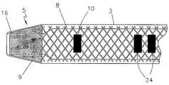
- FIG. 1is a plan view of one embodiment of an endovascular laser treatment sheath according to the present invention.
- FIG. 2is a partial cross-sectional view of the distal section of the endovascular laser treatment sheath of the present invention.
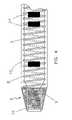
- FIG. 3is a partial plan view of the distal section of the endovascular laser treatment sheath of the present invention with a braided reinforced wire.
- FIG. 4is a partial plan view of the distal section of the endovascular laser treatment sheath of the present invention with a wound reinforcement wire.
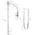
- FIG. 5is a plan view of the endovascular laser treatment sheath of the present invention assembled with a dilator.
- FIG. 6is a partial cross-sectional view of the distal section of the endovascular laser treatment sheath assembled with the dilator.
- FIG. 7is a partial plan view of the endovascular laser treatment sheath and a cross-sectional view of the adjustable depth stop coaxially arranged on the sheath.
- FIG. 8Ashows an ultrasound image of a conventional sheath positioned in a vessel
- FIG. 8Bshows an ultrasound image of a sheath positioned in a vessel according to the present invention.
- the endovascular laser treatment sheath 1is comprised of a hub 2 , shaft 3 with through lumen 4 , and distal tip 5 .
- the hub 2may include a side arm assembly 6 for infusion or aspiration of fluids during the thermal treatment procedure.
- the sheath shaft 3is comprised of a visibly translucent material reinforced with a wire 8 having a predefined pattern such as braided or coil-wound pattern which is embedded within the translucent material, as shown in FIG. 3 .
- the outer wall of the sheath shaft 3may include distance markers 10 .
- An adjustable depth stop 21is coaxially and slidably arranged around the sheath shaft 3 .
- the sheath tip 5has a tapered outer profile as shown in FIG. 2 and FIG. 3 .
- the taperprovides a smooth transition from the outer diameter of the sheath shaft 3 to the smaller outer diameter of the sheath distal tip.
- the taperaids in insertion and advancement and also provides an overall tapered profile when assembled with a dilator 17 as shown in FIG. 5 and FIG. 6 .
- the outer diameter of the sheath shaft 3is approximately 0.079′′ tapering to approximately 0.058′′ at the distal end of the sheath tip 5 .
- the sheathhas an inner diameter of 0.054′′ to allow the dilator 17 to be inserted and advanced through the tip 5 .
- the tapered tip section 5may be as short as practical while ensuring ease of entry and advancement. Optimally, the tapered tip section 5 is 2 mm but may range from 1 to 5 mm in length.
- the tipcontains a fluoroscopically visible tip core 9 encapsulated within a thin layer of the translucent material 16 .
- the fluoroscopically visible tip core 9is made of a polymer with radiopaque filler such as tungsten or barium sulfate for increased visibility under fluoroscopic imaging.
- the tip core 9may be formed using a metallic band encapsulated within the polymer layer or may be designed with an ultrasonically visible filler such as hollow microspheres which create internal air pockets to enhance the reflective characteristics of the tip.
- the radiopaque sheath tipprovides the physician with the option of positioning the sheath tip within the vessel using fluoroscopic or ultrasonic guidance.
- the outer layer 16 of the tipprotects the tissue and vessel from the abrasive characteristics of radiopaque filler material. Specifically, the outer tip layer 16 encapsulates the abrasive radiopaque material providing a smooth, low-friction outer surface during insertion, advancement and withdrawal of the device through the vasculature.
- the shaft 3may be comprised of a translucent material such as nylon or other natural polymer material such as Teflon or polyethylene.
- a translucent materialsuch as nylon or other natural polymer material such as Teflon or polyethylene.
- Prior art endovascular laser sheathscontain fillers or colorants that partially block the red aiming beam and inhibit optimal visibility.
- the translucent shaft material of the current inventiondoes not block the beam's emitting light and thus improves the overall visibility of the red aiming beam through the skin surface as the fiber is inserted through the sheath 1 and advanced through the vein.
- a reinforcement elementsuch as a wire 8 having a predetermined pattern such as a braided or wound pattern.
- FIG. 3shows the wire 8 in a braided configuration.
- An alternative coil-wound or helical wire patternis depicted in FIG. 4 .
- the reinforcing wire 8is embedded within the translucent shaft material for the entire length of the sheath shaft 3 , terminating at the distal tip 5 , as shown in FIG. 3 and 4 .
- the wire 8may be medical grade stainless steel, nitinol or other ultrasonically visible material.
- Flat wire or round wiremay be utilized. The advantage of flat wire includes more reflective surface area for enhanced ultrasonic visibility and a reduced cross-sectional profile. Round wire, on the other hand, is less expensive and easier to manufacture.
- the embedded wire 8provides several key advantages over prior art laser sheaths. It not only serves to enhance shaft visibility under ultrasound imaging, but also provides for an increased maneuverability and kink-resistance during insertion and advancement through the vessel.
- the wire reinforcementalso provides increased durability and resistance against inadvertent needle punctures.
- the wire 8provides a reflective surface for the ultrasonic wave.
- the speed of the ultrasoundchanges from media to media. At each change in the speed of sound, a sound wave echo is reflected or returned and captured by the ultrasonic transducer or probe. As the ultrasound wave travels through the skin, tissue, vein and sheath, echoes are returned. When the ultrasound wave contacts the reinforced wire, the change in media causes an echo to be returned to the probe, resulting in an ultrasonic image with enhanced visibility over conventional, non-reinforced sheath designs.
- the wire 8 reinforced shaftprovides enhanced maneuverability during insertion and advancement through the target vessel.
- shaft material reinforced with an embedded wire patternincreases torquability, (rotation force) and pushability.
- the wire designprovides the user with enhanced control over the sheath's advancement and positioning.
- Wire reinforcementalso provides increased resistance to kinking of the shaft during insertion and advancement.
- the reinforcement wire 8provides both increased visibility and durability over currently available sheaths.
- the reinforcement wire 8with its increased ultrasonic visibility, provides an easily identifiable target for the physician when inserting and positioning the injection needle within the perivenous space.
- the wire 8increases the overall durability of the sheath 1 , providing an added barrier to prevent misaligned needle tips from accidentally puncturing and penetrating the sheath shaft 3 during tumescent injections. Accidental puncture could result in the needle tip coming into direct contact with and damaging the fragile optical fiber, and negatively impacting the clinical outcome of the procedure.
- the combination of improved visibility and durabilitymake it possible to use the sheath shaft 3 as a target for tumescent injections without risking damage to the fiber.
- the transition between the sheath tip 5 and the distal end of the reinforcing wire 8provides a visual landmark for the physician during placement of the tip 5 relative to the sapheno-femoral junction.
- the physiciancan obtain a visual image clearly demarking where the sheath tip 5 ends and the reinforced wire 8 shaft begins.
- the distal end of the reinforcing wireprovides a landmark for the physician.
- FIGS. 8A and 8BThe visual effects of the ultrasonically visible reinforcing wire 8 during placement is shown in FIGS. 8A and 8B .
- FIG. 8Ashows an ultrasound image of a conventional sheath positioned in a vessel and FIG.
- FIG. 8Bshows an ultrasound image of a sheath positioned in a vessel according to the present invention.
- the sheath and the sheath tip according to the invention in FIG. 8Bis much more visible than the prior art sheath in FIG. 8A .
- the sheath tip 5itself will be ultrasonically visible if designed with embedded hollow microspheres, as previously discussed. Under fluoroscopic guidance, the radiopaque qualities of the tip 5 provides the visual landmark for final positioning prior to the activation of laser energy.
- the sheath shaft 3may optionally include a plurality of visual markings 10 uniformly spaced on the shaft outer surface at pre-determined distances, as illustrated in FIG. 1 .
- the markingsprovide a visual indication of insertion depth, tip position, and withdrawal rates.
- the markings 10are preferably in 1 cm increments along the entire length of the shaft, although other distance increments may be used.
- the markingsmay be numbered or otherwise designed to provide the user with an indication as to actual distance from the sheath tip 5 .
- the markingsmay be positioned around the entire circumference of the sheath shaft 3 or may cover only a portion of the shaft 3 circumference as depicted in FIG. 1 .
- the physicianmeasures on the skin surface the distance from the puncture site to the sapheno-femoral junction or other venous target.
- the sheath marking 10corresponding to the physician's measurement then provides an approximate indication as to the length the sheath 1 should be inserted to reach the anatomical target.
- the markings 10also provide an approximate indication of sheath tip 5 position within the vessel.
- the sheath markings 10can be used to provide the physician with an indication of pullback rate of the sheath.
- one of the markings 10 located near the sheath tip 5may be designed to be visually different from the other markings.
- This marking 24provides a unique visual mark to alert the physician that the optical fiber tip is nearing the access tract.
- the physicianbegins to prepare for the end of the procedure when the sheath tip 5 is about 2 centimeters from the access tract.
- the unique marking 24 at a distance of about 2 centimeters from the sheath tip 5provides the physician with an indication of the tip position relative to the puncture tract.
- the unique marking 24may be in the form of a different color, pattern or shape to distinguish it from other markings.
- the depth indicator 21is a tubular structure made of a flexible, elastomeric material such as silicone.
- the indicator 21is dimensioned so that the through hole is slightly smaller than the outer diameter of the sheath shaft 3 yet large enough to be longitudinally slideable along the shaft 3 .
- This interference fit between the shaft 3 and the adjustable depth indicator 21allows the depth indicator 21 to be manually positioned by the physician. Once positioned, the depth indicator 21 will remain in the set position due to the interference fit or friction with the shaft 3 .
- the depth indicator 21provides the physician with an easy and simple method of indicating the location on the shaft where the device 1 exits from the puncture site when positioned just below the sapheno-femoral junction or other reflux point. Like the markings 10 described above, the depth indicator 21 provides an approximate indication as to the length the sheath should be inserted to reach the target position within the vessel.
- the adjustable depth stop 21also performs the function of reducing the risk of longitudinal sheath movement once the device has been positioned. Often, as tumescent injections are administered along the length of the vein, the vein may elongate causing the sheath 1 to slip proximally.
- the adjustable depth stop 21may be designed to provide a high friction surface to reduce longitudinal movement of the device during injections or during other procedural steps. As shown in FIG. 7 , the adjustable depth stop 21 has an increased skin surface contact area along surface 23 . Surface 23 may have textured surface such as a ridged profile as shown in FIG. 7 . Using a soft material such as urethane may also generate increased friction.
- the ridgesprovide an increased frictional contact surface with the skin that reduces longitudinal movement of the sheath 1 .
- the devicecan be easily repositioned by advancing the sheath 1 into the vein until the adjustable stop 21 once again comes in contact with the skin surface along stop surface 23 .
- the depth stop 21provides a positioning function during initial placement, reduces the risk of longitudinal movement of the sheath 1 during the administration of tumescent injections and other procedural steps, and allows for easy repositioning of the device if necessary.
- the sheath hub 2typically includes a hemostasis valve as shown in FIG. 1 and 5 .
- the hub 2includes a valve gasket 11 that provides a leak-proof seal to prevent the backflow of blood out of the sheath hub 2 opening while simultaneously allowing the introduction of fibers, guidewires and other interventional devices into the sheath 1 .
- the valve gasket 11is made of elastomeric material, as is commonly found in the art. The gasket 11 opens to receive the optical fiber (not shown) and then seals around the fiber. However, the valve gasket 11 does not open in response to pressure from the distal side in order to prevent the back-flow of blood or other fluids. The gasket 11 also prevents air from entering the sheath through the hub 2 .
- the hub 2also includes a standard luer threaded proximal end 15 for a threaded connection to a dilator hub 19 or other interventional devices.
- luer threaded hubsare normally used in the medical device industry, any mating connection for connecting two medical components together may be used.
- the hub 2may optionally include a side arm assembly 6 comprised of a side arm port 7 , side arm tubing 12 and a three-way stopcock 13 .
- the side arm assembly 6is used to flush procedural fluids through the sheath lumen 4 .
- the handle 22 on the three-way stopcock 13controls the fluid path.
- fluids injected through the stopcock port 14flows through the lumen of the side arm tubing 12 and the side arm port 7 into the sheath lumen 4 .
- the handle 22is positioned toward the side arm tubing 12 as shown in FIG. 5 , backflow of bodily and procedural fluids are prevented from flowing through the stopcock ports.
- One commonly administered fluid during an endovascular laser treatment procedureis saline which is used to flush blood from the sheath 1 prior to or after insertion of the optical fiber (not shown). Blood is often flushed from the sheath 1 to prevent adherence of blood to the optic fiber, which can adversely affect the intensity of the laser energy within the vessel.
- the side arm assembly 6can also be used to administer emergency drugs directly to the vein or to aspirate fluids from the treatment area.
- the sheath 1 of the current inventionis shown assembled with a standard dilator 17 .
- the function of the dilator 17is to gradually dilate the insertion site so the sheath 1 can be inserted without damage to the tissue surrounding the access site.
- the dilator 17provides a gradual, atraumatic transition from the guidewire diameter, typically 0.035′′ to the full sheath shaft diameter.
- the dilator tipgradually tapers upward to a shaft diameter of 0.054′′.
- the sheath tip 5provides the secondary taper transitioning between the full dilator shaft diameter to full sheath shaft 3 diameter, typically 0.079′′.
- the dilator 17is dimensioned to fit within the lumen 4 of the sheath shaft 3 .
- the dilator tip 18which is tapered inwardly as shown in FIG. 6 , is dimensioned to extend beyond the distal tip 5 of the sheath 1 when fully inserted.
- the distal tip 18 opening of the dilator 17will accommodate an 0.035′′ guidewire.
- a male luer fitting 19provides a connecting means to the sheath hub 2 .
- the female luer 20provides a similar connecting means for other interventional devices and well as providing access to the dilator lumen through the opening in the female luer 20 .
- the treatment procedurebegins with the standard pre-operative preparation of the patient as is well known in the art.
- the patient's diseased venous segmentsare marked on the skin surface.
- ultrasound guidanceis used to map the vein from highest reflux or valve incompetence point to the lowest treatment point.
- An approximate measurement of distance from the access site to the highest point of refluxis then obtained.
- the visual markings 10 on the sheath shaft 3are then used to locate the corresponding distance from the sheath tip 5 to the marking corresponding to the anatomical measurement.
- the designated marking 10 on the sheath shaft 3will be positioned at the puncture or access site, thus providing the physician with an approximate indication of insertion depth.
- the adjustable depth stop 21can be positioned on the sheath shaft 3 at the approximate location representing the approximate length of sheath insertion from the distal tip 5 . After locating the correct position on the sheath, the user simply slides the depth stop 21 to the identified position while holding the sheath 1 stationary.
- the target veinis accessed using a standard Seldinger technique. Under ultrasonic or fluoroscopic guidance, a small gauge needle is used to puncture the skin and access the vein. A guide wire is advanced into the vein through the lumen of the needle. The needle is then removed leaving the guidewire in place.
- the sheath 1 /dilator assembly shown in FIG. 5is introduced into the vein over the guidewire and advanced to 1 to 2 centimeters below the point of reflux, typically sapheno-femoral junction. Positioning is confirmed using either ultrasound or fluoroscopic imaging.
- FIG. 8Ashows an ultrasound image of a conventional sheath positioned in a vessel.
- FIG. 8Billustrates an ultrasound image of the sheath positioned in a vessel according to the present invention, which clearly shows the sheath and its tip.
- FIG. 8Bshows an ultrasound image
- the sheath tip 5 of the current inventionis designed to be clearly visible under either imaging technique.
- the distal end of the reinforcing wirecreates a distinguishing echo, enhancing visibility.
- the internal hollow microspheres embedded in the shaft tip 5 coreprovide enhanced ultrasonic visibility. If fluoroscopic guidance is used, the radiopaque sheath tip is clearly visible.
- the guide wire and dilator 17are removed leaving the sheath 1 in place.
- the distal end of the optical fiberis then inserted into and is advanced through the sheath 1 until the optical fiber emitting end is flush with the sheath tip 5 .
- the red aiming beam feature of the optical fiberis then activated to track progress through the vein.
- the translucent nature of the sheath shaft 3improves the aiming beam visibility during advancement of the optical fiber through the sheath lumen 4 .
- Correct positioning of the sheath tip 5 and fiber tip approximately 1-2 centimeters below the sapheno-femoral junction or other reflux pointis once again confirmed using ultrasound or fluoroscopy. At this point, any required adjustments can be made to the overall device position using the sheath tip 5 and/or reinforced wire 8 as a visual landmark.
- the sheath 1In preparation for laser activation, the sheath 1 is retracted while holding the optical fiber stationary. This action causes the optical fiber tip to become exposed by the proper distance of approximately 2 centimeters from the sheath tip 5 . Once again the imaging guidance features of the sheath tip 5 can be used to confirm correct positioning of sheath 1 and optical fiber after retraction.
- the tissue immediately surrounding the diseased vessel segmentis treated with percutaneous infusions of a tumescent anesthetic agent.
- the physicianinserts a small gauge needle through the skin near the puncture site and into the perivenous space between the vein and the surrounding tissue. If ultrasonic guidance is used, the ultrasound probe is placed on the skin in the proximity of puncture to provide an image of the needle position in the perivenous space.
- the reinforcing wire 8 within the sheath shaft 3provides an enhanced ultrasonic image of the target area. The physician can use the wire 8 , which is clearly visible under ultrasound, to accurately guide and position the needle tip in the perivenous space.
- the wire 8provides a visually enhanced image, but it also provides added protection to the device in the event of inadvertent needle puncture of the sheath 1 .
- the reinforcing wire 8provides an enhanced protective barrier between the fragile optical fiber and the mis-placed needle tip. If the needle tip punctures the sheath shaft 3 , the wire reinforcement 8 provides a physical obstruction to needle advancement, thus reducing the risk of optical fiber damage by the needle tip.
- tumescent injectionis administered and the needle is removed.
- the needleis then repositioned in another location.
- the procedureis repeated until tumescent fluid has been delivered along the entire length of the vein segment being treated.
- tumescent fluidtypically between 5 and 15 separate needle punctures are required to sufficiently anesthetize the area and create a sufficient fluid barrier for treatment.
- the total volume of tumescent fluid injected along the veindepends on the concentration of lidocaine used. For example, if a solution of 0.25% lidocaine is used, up to a maximum of 200 cc may be injected along the course of the vein. Regardless of the concentration used, multiple injections are required. Visibility of the target area is greatly enhanced by the reflective characteristics of the sheath's wire 8 reinforcement, thus reducing the chance of misplacing the needle tip during any of the numerous needle punctures required to completely administer tumescent fluids.
- the adjustable depth stop 21minimizes sheath 1 movement during the tumescent injection.
- the depth stop 21may be used to confirm that the sheath 1 has not slipped proximally during the injections of tumescent anesthesia. If necessary, the sheath 1 can be easily repositioned by advancing it into the vein until the adjustable stop 21 once again comes in contact with the skin surface in the area of the access site. Thus, the depth stop 21 reduces the risk of longitudinal movement of the sheath 1 during pre-procedure preparation and during the procedure itself.
- the stop 21also provides the physician with an easy method of repositioning the sheath if necessary.
- laser energyis applied to the interior of the diseased vein.
- the laser generatoris activated and the combined sheath 1 /optical fiber is then slowly withdrawn as a single unit through the vein, preferably at a rate of 2-3 millimeters per second.
- the laser energytravels down the optical fiber through the tip of the optical fiber and into the vein lumen, where it creates hot bubbles of gas in the bloodstream.
- the gas bubblesexpand to contact the vein wall, along a 360-degree circumference, thus damaging vein wall tissue, and ultimately causing collapse of the vessel.
- the physicianmanually controls the rate at which the sheath 1 /optical fiber is withdrawn.
- the markings 10 on the sheath 1can be used to assist the physician in maintaining an accurate and consistent withdrawal rate.
- the physiciancan adjust the rate of withdrawal by monitoring the appearance of markings 10 at the puncture site within a particular time period, and adjusting the pullback rate accordingly.
- the procedure for treating the varicose veinis considered to be complete when the desired length of the target vein has been exposed to laser energy.
- the laser generatoris turned off when the fiber tip is approximately 3 centimeters from the access site.
- the physiciancan monitor the location of the tip relative to the puncture site in two different ways.
- the markings 10 on the surface of the sheath 1 as they become visible at the puncture site during pullbackcan be used to determine the location of the distal tip 5 .
- the appearance at the access site of the unique marking 24may also be used to determine the location of the sheath tip 5 and to alert the physician that the procedure is almost complete.
- the physiciancontinues to pull back the device until the sheath tip 5 , with its distinctive color, appears at the access site.
- the distal end of the fibertypically extends 2 to 2.5 cm beyond the sheath tip 5 .
- the fiber tip emitting endwill be approximately 3 centimeters below the skin opening.
- the generatoris turned off and the combined sheath 1 /optical fiber device can then be removed from the body as a single unit.
- the appearance of the colored sheath tip at the puncture siteprovides a visual signal to the physician that the entire vein segment has been treated and the laser energy can be turned off.
- the invention disclosed hereinhas numerous advantages over prior art treatment devices and methods.
- the endovascular sheath apparatus and method for venous reflux treatment of the present inventionprovides for optimized visibility under both fluoroscopic and ultrasonic imaging modalities.
- the physicianhas the option of using the same device under either imaging modality.
- the sheathdoes not block or decrease the visibility of red aiming beam feature of the laser system because of the translucent shaft material of the sheath.
- the addition of reinforcing wire to the sheath shaftprovides for enhanced visibility and increases overall durability of the device, particularly during multiple tumescent injections with a needle.
- the wire reinforcementalso adds to the maneuverability of the device during insertion, advancement and withdrawal by increasing shaft torquability, pushability and kink-resistance.
- the devicealso allows enhanced visibility of the sheath tip leading to increased accuracy during final positioning of the device near the sapheno-femoral junction.
- optional markers and the adjustable depth stopprovide the user with a simple, yet effective, technique for identifying sheath insertion distances.
- the depth stopmay also act as a retention mechanism to hold the sheath stationary prior to and during the procedure.
- important advantages of the endovascular laser sheath systeminclude increased visibility under imaging, flexibility in the choice of imaging technique, increased control during advancement through the vessel, improved accuracy in placement of the sheath within the vessel, and added protection of the delicate optical fiber during tumescent injections.
- the invention disclosed hereinalso increases the physician's ability to maintain a consistent pullback speed during the procedure and to accurately assess when the entire length of the vein has been treated.
- the above description and the figuresdisclose particular embodiments of an endovascular sheath system and method of treatment. It should be noted that various modifications to the device and method might be made without departing from the scope of the invention.
- the reinforced wire configurationmay be of various patterns and wire diameters. Hub fittings other than those specifically described herein are within the scope of this invention.
- the use of a dilator as described abovemay not be required.
- Sheath dimensionsmay be decreased to accommodate smaller optical fibers such as 400-micron sizes.
- Endovenous thermal treatment modalities other than lasermay be used including microwave or radio-frequency energy. Veins other than the great saphenous vein can be treated using the method described herein. Accordingly, the scope of the invention is not limited to the foregoing specification, but instead is given by the appended claims along with their full range of equivalents.
Landscapes
- Health & Medical Sciences (AREA)
- Surgery (AREA)
- Physics & Mathematics (AREA)
- Life Sciences & Earth Sciences (AREA)
- Heart & Thoracic Surgery (AREA)
- Medical Informatics (AREA)
- Nuclear Medicine, Radiotherapy & Molecular Imaging (AREA)
- Electromagnetism (AREA)
- Engineering & Computer Science (AREA)
- Biomedical Technology (AREA)
- Optics & Photonics (AREA)
- Otolaryngology (AREA)
- Molecular Biology (AREA)
- Animal Behavior & Ethology (AREA)
- General Health & Medical Sciences (AREA)
- Public Health (AREA)
- Veterinary Medicine (AREA)
- Laser Surgery Devices (AREA)
- Media Introduction/Drainage Providing Device (AREA)
- Surgical Instruments (AREA)
Abstract
Description
Claims (14)
Priority Applications (5)
| Application Number | Priority Date | Filing Date | Title |
|---|---|---|---|
| US10/836,084US7458967B2 (en) | 2003-10-31 | 2004-04-30 | Endovascular treatment apparatus and method |
| CA002482467ACA2482467A1 (en) | 2003-10-31 | 2004-09-22 | Endovascular treatment apparatus and method |
| EP04256733AEP1527748A1 (en) | 2003-10-31 | 2004-11-01 | Apparatus for thermal vascular treament |
| US12/109,835US20080208180A1 (en) | 2002-07-10 | 2008-04-25 | Endovascular treatment sheath having a heat insulative tip and method for using the same |
| US12/138,134US8887733B2 (en) | 2003-10-31 | 2008-06-12 | Endovascular treatment apparatus and method |
Applications Claiming Priority (2)
| Application Number | Priority Date | Filing Date | Title |
|---|---|---|---|
| US51615603P | 2003-10-31 | 2003-10-31 | |
| US10/836,084US7458967B2 (en) | 2003-10-31 | 2004-04-30 | Endovascular treatment apparatus and method |
Related Parent Applications (1)
| Application Number | Title | Priority Date | Filing Date |
|---|---|---|---|
| US11/362,239Continuation-In-PartUS8413664B2 (en) | 2002-07-10 | 2006-02-24 | Method of thermally treating blood vessels |
Related Child Applications (2)
| Application Number | Title | Priority Date | Filing Date |
|---|---|---|---|
| US10/613,395Continuation-In-PartUS7273478B2 (en) | 2002-07-10 | 2003-07-03 | Endovascular treatment device having a fiber tip spacer |
| US12/138,134DivisionUS8887733B2 (en) | 2003-10-31 | 2008-06-12 | Endovascular treatment apparatus and method |
Publications (2)
| Publication Number | Publication Date |
|---|---|
| US20050096642A1 US20050096642A1 (en) | 2005-05-05 |
| US7458967B2true US7458967B2 (en) | 2008-12-02 |
Family
ID=34426333
Family Applications (2)
| Application Number | Title | Priority Date | Filing Date |
|---|---|---|---|
| US10/836,084Expired - Fee RelatedUS7458967B2 (en) | 2002-07-10 | 2004-04-30 | Endovascular treatment apparatus and method |
| US12/138,134Active2028-03-21US8887733B2 (en) | 2003-10-31 | 2008-06-12 | Endovascular treatment apparatus and method |
Family Applications After (1)
| Application Number | Title | Priority Date | Filing Date |
|---|---|---|---|
| US12/138,134Active2028-03-21US8887733B2 (en) | 2003-10-31 | 2008-06-12 | Endovascular treatment apparatus and method |
Country Status (3)
| Country | Link |
|---|---|
| US (2) | US7458967B2 (en) |
| EP (1) | EP1527748A1 (en) |
| CA (1) | CA2482467A1 (en) |
Cited By (61)
| Publication number | Priority date | Publication date | Assignee | Title |
|---|---|---|---|---|
| US20050288655A1 (en)* | 2004-06-29 | 2005-12-29 | Howard Root | Laser fiber for endovenous therapy having a shielded distal tip |
| US20060142747A1 (en)* | 2002-12-11 | 2006-06-29 | Appling William M | Method of thermally treating blood vessels |
| US20070179486A1 (en)* | 2004-06-29 | 2007-08-02 | Jeff Welch | Laser fiber for endovenous therapy having a shielded distal tip |
| US20070179575A1 (en)* | 2005-07-21 | 2007-08-02 | Esch Brady D | Thermal therapeutic catheter with location detection enhancement |
| US8291915B2 (en) | 1997-03-04 | 2012-10-23 | Tyco Healthcare Group Lp | Method and apparatus for treating venous insufficiency using directionally applied energy |
| US8435235B2 (en) | 2007-04-27 | 2013-05-07 | Covidien Lp | Systems and methods for treating hollow anatomical structures |
| US9286673B2 (en) | 2012-10-05 | 2016-03-15 | Volcano Corporation | Systems for correcting distortions in a medical image and methods of use thereof |
| US9292918B2 (en) | 2012-10-05 | 2016-03-22 | Volcano Corporation | Methods and systems for transforming luminal images |
| US9301687B2 (en) | 2013-03-13 | 2016-04-05 | Volcano Corporation | System and method for OCT depth calibration |
| US9307926B2 (en) | 2012-10-05 | 2016-04-12 | Volcano Corporation | Automatic stent detection |
| US9324141B2 (en) | 2012-10-05 | 2016-04-26 | Volcano Corporation | Removal of A-scan streaking artifact |
| US9360630B2 (en) | 2011-08-31 | 2016-06-07 | Volcano Corporation | Optical-electrical rotary joint and methods of use |
| US9367965B2 (en) | 2012-10-05 | 2016-06-14 | Volcano Corporation | Systems and methods for generating images of tissue |
| US9383263B2 (en) | 2012-12-21 | 2016-07-05 | Volcano Corporation | Systems and methods for narrowing a wavelength emission of light |
| US9478940B2 (en) | 2012-10-05 | 2016-10-25 | Volcano Corporation | Systems and methods for amplifying light |
| US9486143B2 (en) | 2012-12-21 | 2016-11-08 | Volcano Corporation | Intravascular forward imaging device |
| US20170031024A1 (en)* | 2015-07-30 | 2017-02-02 | Seiko Epson Corporation | Ultrasonic device, ultrasonic module, electronic apparatus, and ultrasonic measurement apparatus |
| US20170035990A1 (en)* | 2015-08-04 | 2017-02-09 | Kevin Swift | Endoluminal fluid delivery device and method |
| US9596993B2 (en) | 2007-07-12 | 2017-03-21 | Volcano Corporation | Automatic calibration systems and methods of use |
| US9612105B2 (en) | 2012-12-21 | 2017-04-04 | Volcano Corporation | Polarization sensitive optical coherence tomography system |
| US9622706B2 (en) | 2007-07-12 | 2017-04-18 | Volcano Corporation | Catheter for in vivo imaging |
| US9709379B2 (en) | 2012-12-20 | 2017-07-18 | Volcano Corporation | Optical coherence tomography system that is reconfigurable between different imaging modes |
| US9730613B2 (en) | 2012-12-20 | 2017-08-15 | Volcano Corporation | Locating intravascular images |
| US9770172B2 (en) | 2013-03-07 | 2017-09-26 | Volcano Corporation | Multimodal segmentation in intravascular images |
| US9770297B2 (en) | 2008-06-04 | 2017-09-26 | Covidien Lp | Energy devices and methods for treating hollow anatomical structures |
| US9858668B2 (en) | 2012-10-05 | 2018-01-02 | Volcano Corporation | Guidewire artifact removal in images |
| US9867530B2 (en) | 2006-08-14 | 2018-01-16 | Volcano Corporation | Telescopic side port catheter device with imaging system and method for accessing side branch occlusions |
| US10058284B2 (en) | 2012-12-21 | 2018-08-28 | Volcano Corporation | Simultaneous imaging, monitoring, and therapy |
| US10070827B2 (en) | 2012-10-05 | 2018-09-11 | Volcano Corporation | Automatic image playback |
| US10166003B2 (en) | 2012-12-21 | 2019-01-01 | Volcano Corporation | Ultrasound imaging with variable line density |
| US10191220B2 (en) | 2012-12-21 | 2019-01-29 | Volcano Corporation | Power-efficient optical circuit |
| US10219780B2 (en) | 2007-07-12 | 2019-03-05 | Volcano Corporation | OCT-IVUS catheter for concurrent luminal imaging |
| US10219887B2 (en) | 2013-03-14 | 2019-03-05 | Volcano Corporation | Filters with echogenic characteristics |
| US10226597B2 (en) | 2013-03-07 | 2019-03-12 | Volcano Corporation | Guidewire with centering mechanism |
| US10238367B2 (en) | 2012-12-13 | 2019-03-26 | Volcano Corporation | Devices, systems, and methods for targeted cannulation |
| US10292677B2 (en) | 2013-03-14 | 2019-05-21 | Volcano Corporation | Endoluminal filter having enhanced echogenic properties |
| US10332228B2 (en) | 2012-12-21 | 2019-06-25 | Volcano Corporation | System and method for graphical processing of medical data |
| US10413317B2 (en) | 2012-12-21 | 2019-09-17 | Volcano Corporation | System and method for catheter steering and operation |
| US10420530B2 (en) | 2012-12-21 | 2019-09-24 | Volcano Corporation | System and method for multipath processing of image signals |
| US10426590B2 (en) | 2013-03-14 | 2019-10-01 | Volcano Corporation | Filters with echogenic characteristics |
| US10568586B2 (en) | 2012-10-05 | 2020-02-25 | Volcano Corporation | Systems for indicating parameters in an imaging data set and methods of use |
| US10595820B2 (en) | 2012-12-20 | 2020-03-24 | Philips Image Guided Therapy Corporation | Smooth transition catheters |
| US10638939B2 (en) | 2013-03-12 | 2020-05-05 | Philips Image Guided Therapy Corporation | Systems and methods for diagnosing coronary microvascular disease |
| US10724082B2 (en) | 2012-10-22 | 2020-07-28 | Bio-Rad Laboratories, Inc. | Methods for analyzing DNA |
| US10758207B2 (en) | 2013-03-13 | 2020-09-01 | Philips Image Guided Therapy Corporation | Systems and methods for producing an image from a rotational intravascular ultrasound device |
| US10939826B2 (en) | 2012-12-20 | 2021-03-09 | Philips Image Guided Therapy Corporation | Aspirating and removing biological material |
| US10942022B2 (en) | 2012-12-20 | 2021-03-09 | Philips Image Guided Therapy Corporation | Manual calibration of imaging system |
| US10993694B2 (en) | 2012-12-21 | 2021-05-04 | Philips Image Guided Therapy Corporation | Rotational ultrasound imaging catheter with extended catheter body telescope |
| US11026591B2 (en) | 2013-03-13 | 2021-06-08 | Philips Image Guided Therapy Corporation | Intravascular pressure sensor calibration |
| US11040140B2 (en) | 2010-12-31 | 2021-06-22 | Philips Image Guided Therapy Corporation | Deep vein thrombosis therapeutic methods |
| US11141063B2 (en) | 2010-12-23 | 2021-10-12 | Philips Image Guided Therapy Corporation | Integrated system architectures and methods of use |
| US11154313B2 (en) | 2013-03-12 | 2021-10-26 | The Volcano Corporation | Vibrating guidewire torquer and methods of use |
| US11272845B2 (en) | 2012-10-05 | 2022-03-15 | Philips Image Guided Therapy Corporation | System and method for instant and automatic border detection |
| US11406498B2 (en) | 2012-12-20 | 2022-08-09 | Philips Image Guided Therapy Corporation | Implant delivery system and implants |
| US11576724B2 (en) | 2011-02-24 | 2023-02-14 | Eximo Medical Ltd. | Hybrid catheter for vascular intervention |
| US11684420B2 (en) | 2016-05-05 | 2023-06-27 | Eximo Medical Ltd. | Apparatus and methods for resecting and/or ablating an undesired tissue |
| US11877784B2 (en) | 2014-03-26 | 2024-01-23 | Venclose, Inc. | Venous disease treatment |
| US12038322B2 (en) | 2022-06-21 | 2024-07-16 | Eximo Medical Ltd. | Devices and methods for testing ablation systems |
| US12201477B2 (en) | 2012-10-05 | 2025-01-21 | Philips Image Guided Therapy Corporation | Methods and systems for establishing parameters for three-dimensional imaging |
| US12343198B2 (en) | 2013-03-14 | 2025-07-01 | Philips Image Guided Therapy Corporation | Delivery catheter having imaging capabilities |
| US12376904B1 (en) | 2020-09-08 | 2025-08-05 | Angiodynamics, Inc. | Dynamic laser stabilization and calibration system |
Families Citing this family (73)
| Publication number | Priority date | Publication date | Assignee | Title |
|---|---|---|---|---|
| US7789876B2 (en) | 2000-08-14 | 2010-09-07 | Tyco Healthcare Group, Lp | Method and apparatus for positioning a catheter relative to an anatomical junction |
| EP2134282B1 (en) | 2002-07-10 | 2019-05-22 | AngioDynamics, Inc. | Device for endovascular treatment for causing closure of a blood vessel |
| US20080188740A1 (en)* | 2004-01-14 | 2008-08-07 | Diaz Cesar M | Apparatus and method for guiding catheters |
| US20070219444A1 (en)* | 2004-01-14 | 2007-09-20 | Diaz Cesar M | Apparatus and method for guiding catheters |
| US20070016272A1 (en) | 2004-09-27 | 2007-01-18 | Thompson Russell B | Systems and methods for treating a hollow anatomical structure |
| US8954134B2 (en) | 2005-09-13 | 2015-02-10 | Children's Medical Center Corporation | Light-guided transluminal catheter |
| US20070073160A1 (en) | 2005-09-13 | 2007-03-29 | Children's Medical Center Corporation | Light-guided transluminal catheter |
| GB0603866D0 (en)* | 2006-02-27 | 2006-04-05 | Diomed Inc | Medical laser device |
| CN101547653B (en) | 2006-09-13 | 2012-02-29 | 瓦斯库勒英赛特有限公司 | Vascular Therapy Devices |
| US9855021B2 (en)* | 2006-10-12 | 2018-01-02 | Perceptive Navigation, LLC | Image guided catheters and methods of use |
| US10772600B2 (en) | 2015-09-25 | 2020-09-15 | Perceptive Navigation Llc | Image guided catheters and methods of use |
| EP1914576B1 (en) | 2006-10-17 | 2019-01-16 | Dornier MedTech Laser GmbH | Laser applicator with an optical lightguide, the optical lightguide comprising a photorefractive section having a volume hologram. |
| US20080200909A1 (en)* | 2006-11-16 | 2008-08-21 | Lawler David E | Laser fiber holder |
| US20080287965A1 (en)* | 2007-05-17 | 2008-11-20 | Richard Ducharme | Radiopaque band ligator |
| US8298215B2 (en)* | 2007-09-25 | 2012-10-30 | Vascular Solutions, Inc. | Guidewire tipped laser fiber |
| WO2009130049A1 (en)* | 2008-04-25 | 2009-10-29 | Curalux Gbr | Light-based method for the endovascular treatment of pathologically altered blood vessels |
| US8272383B2 (en)* | 2008-05-06 | 2012-09-25 | Nxthera, Inc. | Systems and methods for male sterilization |
| WO2010019481A1 (en) | 2008-08-11 | 2010-02-18 | Conceptx Medical, Inc. | Systems and methods for treating dyspnea, including via electrical afferent signal blocking |
| US20100049085A1 (en)* | 2008-08-22 | 2010-02-25 | Nock Andrew P | Method of making a biopsy marker delivery device |
| US8532747B2 (en)* | 2008-08-22 | 2013-09-10 | Devicor Medical Products, Inc. | Biopsy marker delivery device |
| US20110270090A1 (en)* | 2008-09-18 | 2011-11-03 | Timothy Earl Morey | Needle having ultrasound opaque elements |
| US9561066B2 (en) | 2008-10-06 | 2017-02-07 | Virender K. Sharma | Method and apparatus for tissue ablation |
| US10695126B2 (en) | 2008-10-06 | 2020-06-30 | Santa Anna Tech Llc | Catheter with a double balloon structure to generate and apply a heated ablative zone to tissue |
| US9700365B2 (en) | 2008-10-06 | 2017-07-11 | Santa Anna Tech Llc | Method and apparatus for the ablation of gastrointestinal tissue |
| US9561068B2 (en) | 2008-10-06 | 2017-02-07 | Virender K. Sharma | Method and apparatus for tissue ablation |
| US10064697B2 (en) | 2008-10-06 | 2018-09-04 | Santa Anna Tech Llc | Vapor based ablation system for treating various indications |
| CN102271595A (en) | 2008-11-06 | 2011-12-07 | 恩克斯特拉公司 | Systems and methods for treatment of bph |
| CN105434039B (en)* | 2008-11-06 | 2019-01-15 | 恩克斯特拉公司 | System and method for treating prostata tissue |
| JP2012508068A (en) | 2008-11-06 | 2012-04-05 | エヌエックスセラ インコーポレイテッド | System and method for treatment of prostate tissue |
| US8388611B2 (en) | 2009-01-14 | 2013-03-05 | Nxthera, Inc. | Systems and methods for treatment of prostatic tissue |
| US9833277B2 (en) | 2009-04-27 | 2017-12-05 | Nxthera, Inc. | Systems and methods for prostate treatment |
| US20100298948A1 (en)* | 2009-04-27 | 2010-11-25 | Michael Hoey | Systems and Methods for Prostate Treatment |
| WO2011019884A2 (en)* | 2009-08-12 | 2011-02-17 | Global Vein Solutions, Llc | Tumescent anesthesia delivery in conjunction with endovenous vein therapy |
| US20110257563A1 (en)* | 2009-10-26 | 2011-10-20 | Vytronus, Inc. | Methods and systems for ablating tissue |
| EP2549963B1 (en) | 2010-03-25 | 2023-08-23 | Boston Scientific Scimed, Inc. | Systems for prostate treatment |
| US9585667B2 (en) | 2010-11-15 | 2017-03-07 | Vascular Insights Llc | Sclerotherapy catheter with lumen having wire rotated by motor and simultaneous withdrawal from vein |
| US8992513B2 (en) | 2011-06-30 | 2015-03-31 | Angiodynamics, Inc | Endovascular plasma treatment device and method of use |
| CN103917200B (en) | 2011-09-13 | 2016-03-30 | 恩克斯特拉公司 | Systems and methods for prostate treatment |
| EP2833815B1 (en) | 2012-04-03 | 2020-11-11 | Boston Scientific Scimed, Inc. | Induction coil vapor generator |
| WO2013163322A1 (en) | 2012-04-24 | 2013-10-31 | Cibiem, Inc. | Endovascular catheters and methods for carotid body ablation |
| WO2013181660A1 (en) | 2012-06-01 | 2013-12-05 | Cibiem, Inc. | Methods and devices for cryogenic carotid body ablation |
| EP2854681A4 (en) | 2012-06-01 | 2016-02-17 | Cibiem Inc | Percutaneous methods and devices for carotid body ablation |
| WO2014005155A1 (en) | 2012-06-30 | 2014-01-03 | Cibiem, Inc. | Carotid body ablation via directed energy |
| WO2014011403A1 (en)* | 2012-07-11 | 2014-01-16 | The University Of Connecticut | Dual-modality endoscope, method of manufacture, and use thereof |
| TWI541001B (en)* | 2012-08-09 | 2016-07-11 | 國立成功大學 | Electromagnetic thermotherapy needle |
| US20140200402A1 (en)* | 2013-01-16 | 2014-07-17 | Phillip Jack Snoke | Medical Device Introduction Systems and Methods |
| EP3964151A3 (en) | 2013-01-17 | 2022-03-30 | Virender K. Sharma | Apparatus for tissue ablation |
| BR112015022358A2 (en) | 2013-03-14 | 2017-07-18 | Nxthera Inc | method for treating abnormal prostate tissue, and, method for treating prostate cancer, and, prostate cancer therapy system |
| US20150216601A1 (en)* | 2013-03-15 | 2015-08-06 | Joe Denton Brown | Protective sheath positioning arrangement and method, and miniature fiber lock connector for use therewith |
| US10194970B2 (en) | 2013-12-10 | 2019-02-05 | Nxthera, Inc. | Vapor ablation systems and methods |
| US9968395B2 (en) | 2013-12-10 | 2018-05-15 | Nxthera, Inc. | Systems and methods for treating the prostate |
| US9629981B2 (en)* | 2013-12-13 | 2017-04-25 | Dolcera Information Technology Services Private Limited | Drainage catheter |
| EP3116408B1 (en) | 2014-03-12 | 2018-12-19 | Cibiem, Inc. | Ultrasound ablation catheter |
| JP6220056B2 (en)* | 2014-04-16 | 2017-10-25 | 株式会社パイオラックスメディカルデバイス | Guide wire |
| US10342593B2 (en) | 2015-01-29 | 2019-07-09 | Nxthera, Inc. | Vapor ablation systems and methods |
| CA2976805C (en)* | 2015-02-23 | 2020-04-07 | C.R. Bard, Inc. | Access system |
| CA2982372A1 (en) | 2015-05-13 | 2016-11-17 | Nxthera, Inc. | Systems and methods for treating the bladder with condensable vapor |
| US11027141B2 (en) | 2015-09-25 | 2021-06-08 | Innoscion Llc | Pericardial implantable cardioverter defibrillator |
| USD816215S1 (en) | 2016-02-23 | 2018-04-24 | C.R. Bard Inc. | Access device |
| WO2017189577A1 (en)* | 2016-04-26 | 2017-11-02 | Boston Scientific Limited | Percutaneous access device with adjustable depth stop |
| US12364537B2 (en) | 2016-05-02 | 2025-07-22 | Santa Anna Tech Llc | Catheter with a double balloon structure to generate and apply a heated ablative zone to tissue |
| US11331140B2 (en) | 2016-05-19 | 2022-05-17 | Aqua Heart, Inc. | Heated vapor ablation systems and methods for treating cardiac conditions |
| JP7129980B2 (en) | 2016-12-21 | 2022-09-02 | ボストン サイエンティフィック サイムド,インコーポレイテッド | Steam cautery system and method |
| WO2018129466A1 (en) | 2017-01-06 | 2018-07-12 | Nxthera, Inc. | Transperineal vapor ablation systems and methods |
| US11364077B2 (en)* | 2017-03-24 | 2022-06-21 | The Spectranetics Corporation | Laser energy delivery devices including distal tip orientation indicators |
| US20190000558A1 (en) | 2017-06-28 | 2019-01-03 | Theodore P. Abraham | Devices and methods for image-guided percutaneous cardiac valve implantation and repair |
| US10758214B2 (en) | 2017-11-13 | 2020-09-01 | UVision360, Inc. | Biopsy device and method |
| EP3801324B1 (en) | 2018-06-01 | 2025-05-28 | Aqua Medical, Inc. | Vapor generation and delivery systems |
| KR102011399B1 (en)* | 2018-10-10 | 2019-08-16 | 주식회사 코러스트 | Ultrasound apparatus of body cavity insertable type with separable sealing cover |
| US10863886B2 (en) | 2019-05-03 | 2020-12-15 | UVision360, Inc. | Rotatable introducers |
| US20200353215A1 (en)* | 2019-05-06 | 2020-11-12 | Baylis Medical Company Inc. | System and Methods for Left Atrial Access |
| FR3095765A1 (en)* | 2019-05-07 | 2020-11-13 | Prüfer Et Associes | Introducer catheter and specific guide for endovenous laser treatment, and method of assisting the placement of this introducer catheter |
| US12232707B2 (en)* | 2021-01-26 | 2025-02-25 | Arthrex, Inc. | Endoscope thermal reflector |
Citations (18)
| Publication number | Priority date | Publication date | Assignee | Title |
|---|---|---|---|---|
| US3605750A (en) | 1969-04-07 | 1971-09-20 | David S Sheridan | X-ray tip catheter |
| GB1533204A (en) | 1976-09-07 | 1978-11-22 | Leveen H | Flexible tubing |
| US4697595A (en) | 1984-07-24 | 1987-10-06 | Telectronics N.V. | Ultrasonically marked cardiac catheters |
| DE8905642U1 (en) | 1989-05-05 | 1989-08-10 | REHAU AG + Co, 8673 Rehau | Catheter tube |
| US5342383A (en) | 1992-03-27 | 1994-08-30 | Thomas Medical Products, Inc. | Soft tip obturator |
| US5456680A (en)* | 1993-09-14 | 1995-10-10 | Spectranetics Corp | Fiber optic catheter with shortened guide wire lumen |
| US5643251A (en)* | 1992-08-18 | 1997-07-01 | Spectranetics Corporation | Fibert optic guide wire and support catheter therefor |
| US5693043A (en)* | 1985-03-22 | 1997-12-02 | Massachusetts Institute Of Technology | Catheter for laser angiosurgery |
| US5695482A (en)* | 1991-07-23 | 1997-12-09 | Intermed, Inc. | UV treated catheter |
| US5700243A (en)* | 1992-10-30 | 1997-12-23 | Pdt Systems, Inc. | Balloon perfusion catheter |
| US6056743A (en)* | 1997-11-04 | 2000-05-02 | Scimed Life Systems, Inc. | Percutaneous myocardial revascularization device and method |
| US6126654A (en) | 1997-04-04 | 2000-10-03 | Eclipse Surgical Technologies, Inc. | Method of forming revascularization channels in myocardium using a steerable catheter |
| US20020072680A1 (en)* | 2000-12-12 | 2002-06-13 | Schock Robert B. | Intra-aortic balloon catheter having a fiberoptic sensor |
| US20030050686A1 (en)* | 1999-05-14 | 2003-03-13 | Raeder-Devens Jennifer E. | Prosthesis deployment device with translucent distal end |
| US6551302B1 (en)* | 1997-09-24 | 2003-04-22 | Michael J. Rosinko | Steerable catheter with tip alignment and surface contact detector |
| US20030199860A1 (en) | 2002-04-22 | 2003-10-23 | Loeb Marvin P. | Devices and methods for directed, interstitial ablation of tissue |
| US20040093044A1 (en)* | 2002-08-05 | 2004-05-13 | Rychnovsky Steven J. | Light delivery catheter |
| US20070073160A1 (en)* | 2005-09-13 | 2007-03-29 | Children's Medical Center Corporation | Light-guided transluminal catheter |
Family Cites Families (5)
| Publication number | Priority date | Publication date | Assignee | Title |
|---|---|---|---|---|
| US6398777B1 (en)* | 1999-02-01 | 2002-06-04 | Luis Navarro | Endovascular laser device and treatment of varicose veins |
| US7912554B2 (en)* | 2001-09-26 | 2011-03-22 | Medtronic Cryocath Lp | Method for treatment of aneurysms |
| US9440046B2 (en)* | 2002-04-04 | 2016-09-13 | Angiodynamics, Inc. | Venous insufficiency treatment method |
| US7163533B2 (en)* | 2002-04-04 | 2007-01-16 | Angiodynamics, Inc. | Vascular treatment device and method |
| US7524316B2 (en)* | 2002-10-31 | 2009-04-28 | Cooltouch, Inc. | Endovenous closure of varicose veins with mid infrared laser |
- 2004
- 2004-04-30USUS10/836,084patent/US7458967B2/ennot_activeExpired - Fee Related
- 2004-09-22CACA002482467Apatent/CA2482467A1/ennot_activeWithdrawn
- 2004-11-01EPEP04256733Apatent/EP1527748A1/ennot_activeWithdrawn
- 2008
- 2008-06-12USUS12/138,134patent/US8887733B2/enactiveActive
Patent Citations (18)
| Publication number | Priority date | Publication date | Assignee | Title |
|---|---|---|---|---|
| US3605750A (en) | 1969-04-07 | 1971-09-20 | David S Sheridan | X-ray tip catheter |
| GB1533204A (en) | 1976-09-07 | 1978-11-22 | Leveen H | Flexible tubing |
| US4697595A (en) | 1984-07-24 | 1987-10-06 | Telectronics N.V. | Ultrasonically marked cardiac catheters |
| US5693043A (en)* | 1985-03-22 | 1997-12-02 | Massachusetts Institute Of Technology | Catheter for laser angiosurgery |
| DE8905642U1 (en) | 1989-05-05 | 1989-08-10 | REHAU AG + Co, 8673 Rehau | Catheter tube |
| US5695482A (en)* | 1991-07-23 | 1997-12-09 | Intermed, Inc. | UV treated catheter |
| US5342383A (en) | 1992-03-27 | 1994-08-30 | Thomas Medical Products, Inc. | Soft tip obturator |
| US5643251A (en)* | 1992-08-18 | 1997-07-01 | Spectranetics Corporation | Fibert optic guide wire and support catheter therefor |
| US5700243A (en)* | 1992-10-30 | 1997-12-23 | Pdt Systems, Inc. | Balloon perfusion catheter |
| US5456680A (en)* | 1993-09-14 | 1995-10-10 | Spectranetics Corp | Fiber optic catheter with shortened guide wire lumen |
| US6126654A (en) | 1997-04-04 | 2000-10-03 | Eclipse Surgical Technologies, Inc. | Method of forming revascularization channels in myocardium using a steerable catheter |
| US6551302B1 (en)* | 1997-09-24 | 2003-04-22 | Michael J. Rosinko | Steerable catheter with tip alignment and surface contact detector |
| US6056743A (en)* | 1997-11-04 | 2000-05-02 | Scimed Life Systems, Inc. | Percutaneous myocardial revascularization device and method |
| US20030050686A1 (en)* | 1999-05-14 | 2003-03-13 | Raeder-Devens Jennifer E. | Prosthesis deployment device with translucent distal end |
| US20020072680A1 (en)* | 2000-12-12 | 2002-06-13 | Schock Robert B. | Intra-aortic balloon catheter having a fiberoptic sensor |
| US20030199860A1 (en) | 2002-04-22 | 2003-10-23 | Loeb Marvin P. | Devices and methods for directed, interstitial ablation of tissue |
| US20040093044A1 (en)* | 2002-08-05 | 2004-05-13 | Rychnovsky Steven J. | Light delivery catheter |
| US20070073160A1 (en)* | 2005-09-13 | 2007-03-29 | Children's Medical Center Corporation | Light-guided transluminal catheter |
Cited By (89)
| Publication number | Priority date | Publication date | Assignee | Title |
|---|---|---|---|---|
| US8291915B2 (en) | 1997-03-04 | 2012-10-23 | Tyco Healthcare Group Lp | Method and apparatus for treating venous insufficiency using directionally applied energy |
| US20060142747A1 (en)* | 2002-12-11 | 2006-06-29 | Appling William M | Method of thermally treating blood vessels |
| US8413664B2 (en)* | 2002-12-11 | 2013-04-09 | Angiodynamics, Inc. | Method of thermally treating blood vessels |
| US20070179486A1 (en)* | 2004-06-29 | 2007-08-02 | Jeff Welch | Laser fiber for endovenous therapy having a shielded distal tip |
| US20050288655A1 (en)* | 2004-06-29 | 2005-12-29 | Howard Root | Laser fiber for endovenous therapy having a shielded distal tip |
| US8721634B2 (en) | 2005-07-21 | 2014-05-13 | Covidien Lp | Apparatus and method for ensuring thermal treatment of a hollow anatomical structure |
| US20070179575A1 (en)* | 2005-07-21 | 2007-08-02 | Esch Brady D | Thermal therapeutic catheter with location detection enhancement |
| US20110034922A1 (en)* | 2005-07-21 | 2011-02-10 | Tyco Healthcare Group, Lp | Systems for treating a hollow anatomical structure |
| US7963961B2 (en)* | 2005-07-21 | 2011-06-21 | Tyco Healthcare Group Lp | Systems for treating a hollow anatomical structure |
| US7963962B2 (en)* | 2005-07-21 | 2011-06-21 | Tyco Healthcare Group Lp | Methods for treating a hollow anatomical structure |
| US8043285B2 (en)* | 2005-07-21 | 2011-10-25 | Tyco Healthcare Group Lp | Systems for treating a hollow anatomical structure |
| US7837677B2 (en)* | 2005-07-21 | 2010-11-23 | Tyco Healthcare Group, Lp | Systems for treating a hollow anatomical structure |
| US8321019B2 (en) | 2005-07-21 | 2012-11-27 | Covidien Lp | Apparatus and method for ensuring safe operation of a thermal treatment catheter |
| US7828793B2 (en)* | 2005-07-21 | 2010-11-09 | Tyco Healthcare Group, Lp | Methods for treating a hollow anatomical structure |
| US10722284B2 (en) | 2005-07-21 | 2020-07-28 | Covidien Lp | Systems for treating a hollow anatomical structure |
| US8636729B2 (en) | 2005-07-21 | 2014-01-28 | Covidien Lp | Therapeutic system with energy application device and programmed power delivery |
| US20200345404A1 (en)* | 2005-07-21 | 2020-11-05 | Covidien Lp | Systems for treating a hollow anatomical structure |
| US8852178B2 (en) | 2005-07-21 | 2014-10-07 | Covidien Lp | Systems for treating a hollow anatomical structure |
| US7837678B2 (en)* | 2005-07-21 | 2010-11-23 | Tyco Healthcare Group, Lp | Systems for treating a hollow anatomical structure |
| US11672587B2 (en)* | 2005-07-21 | 2023-06-13 | Covidien Lp | Systems for treating a hollow anatomical structure |
| US9867530B2 (en) | 2006-08-14 | 2018-01-16 | Volcano Corporation | Telescopic side port catheter device with imaging system and method for accessing side branch occlusions |
| US9547123B2 (en) | 2007-04-27 | 2017-01-17 | Covidien Lp | Systems and methods for treating hollow anatomical structures |
| US8435235B2 (en) | 2007-04-27 | 2013-05-07 | Covidien Lp | Systems and methods for treating hollow anatomical structures |
| US9596993B2 (en) | 2007-07-12 | 2017-03-21 | Volcano Corporation | Automatic calibration systems and methods of use |
| US11350906B2 (en) | 2007-07-12 | 2022-06-07 | Philips Image Guided Therapy Corporation | OCT-IVUS catheter for concurrent luminal imaging |
| US10219780B2 (en) | 2007-07-12 | 2019-03-05 | Volcano Corporation | OCT-IVUS catheter for concurrent luminal imaging |
| US9622706B2 (en) | 2007-07-12 | 2017-04-18 | Volcano Corporation | Catheter for in vivo imaging |
| US9770297B2 (en) | 2008-06-04 | 2017-09-26 | Covidien Lp | Energy devices and methods for treating hollow anatomical structures |
| US11141063B2 (en) | 2010-12-23 | 2021-10-12 | Philips Image Guided Therapy Corporation | Integrated system architectures and methods of use |
| US11040140B2 (en) | 2010-12-31 | 2021-06-22 | Philips Image Guided Therapy Corporation | Deep vein thrombosis therapeutic methods |
| US11576724B2 (en) | 2011-02-24 | 2023-02-14 | Eximo Medical Ltd. | Hybrid catheter for vascular intervention |
| US12042223B2 (en) | 2011-02-24 | 2024-07-23 | Eximo Medical Ltd. | Hybrid catheter for vascular intervention |
| US9360630B2 (en) | 2011-08-31 | 2016-06-07 | Volcano Corporation | Optical-electrical rotary joint and methods of use |
| US9307926B2 (en) | 2012-10-05 | 2016-04-12 | Volcano Corporation | Automatic stent detection |
| US9292918B2 (en) | 2012-10-05 | 2016-03-22 | Volcano Corporation | Methods and systems for transforming luminal images |
| US12201477B2 (en) | 2012-10-05 | 2025-01-21 | Philips Image Guided Therapy Corporation | Methods and systems for establishing parameters for three-dimensional imaging |
| US9286673B2 (en) | 2012-10-05 | 2016-03-15 | Volcano Corporation | Systems for correcting distortions in a medical image and methods of use thereof |
| US11890117B2 (en) | 2012-10-05 | 2024-02-06 | Philips Image Guided Therapy Corporation | Systems for indicating parameters in an imaging data set and methods of use |
| US9858668B2 (en) | 2012-10-05 | 2018-01-02 | Volcano Corporation | Guidewire artifact removal in images |
| US11864870B2 (en) | 2012-10-05 | 2024-01-09 | Philips Image Guided Therapy Corporation | System and method for instant and automatic border detection |
| US10568586B2 (en) | 2012-10-05 | 2020-02-25 | Volcano Corporation | Systems for indicating parameters in an imaging data set and methods of use |
| US10070827B2 (en) | 2012-10-05 | 2018-09-11 | Volcano Corporation | Automatic image playback |
| US11510632B2 (en) | 2012-10-05 | 2022-11-29 | Philips Image Guided Therapy Corporation | Systems for indicating parameters in an imaging data set and methods of use |
| US9324141B2 (en) | 2012-10-05 | 2016-04-26 | Volcano Corporation | Removal of A-scan streaking artifact |
| US11272845B2 (en) | 2012-10-05 | 2022-03-15 | Philips Image Guided Therapy Corporation | System and method for instant and automatic border detection |
| US9367965B2 (en) | 2012-10-05 | 2016-06-14 | Volcano Corporation | Systems and methods for generating images of tissue |
| US9478940B2 (en) | 2012-10-05 | 2016-10-25 | Volcano Corporation | Systems and methods for amplifying light |
| US10724082B2 (en) | 2012-10-22 | 2020-07-28 | Bio-Rad Laboratories, Inc. | Methods for analyzing DNA |
| US10238367B2 (en) | 2012-12-13 | 2019-03-26 | Volcano Corporation | Devices, systems, and methods for targeted cannulation |
| US11406498B2 (en) | 2012-12-20 | 2022-08-09 | Philips Image Guided Therapy Corporation | Implant delivery system and implants |
| US10942022B2 (en) | 2012-12-20 | 2021-03-09 | Philips Image Guided Therapy Corporation | Manual calibration of imaging system |
| US11141131B2 (en) | 2012-12-20 | 2021-10-12 | Philips Image Guided Therapy Corporation | Smooth transition catheters |
| US9730613B2 (en) | 2012-12-20 | 2017-08-15 | Volcano Corporation | Locating intravascular images |
| US10939826B2 (en) | 2012-12-20 | 2021-03-09 | Philips Image Guided Therapy Corporation | Aspirating and removing biological material |
| US10595820B2 (en) | 2012-12-20 | 2020-03-24 | Philips Image Guided Therapy Corporation | Smooth transition catheters |
| US9709379B2 (en) | 2012-12-20 | 2017-07-18 | Volcano Corporation | Optical coherence tomography system that is reconfigurable between different imaging modes |
| US11892289B2 (en) | 2012-12-20 | 2024-02-06 | Philips Image Guided Therapy Corporation | Manual calibration of imaging system |
| US9612105B2 (en) | 2012-12-21 | 2017-04-04 | Volcano Corporation | Polarization sensitive optical coherence tomography system |
| US9486143B2 (en) | 2012-12-21 | 2016-11-08 | Volcano Corporation | Intravascular forward imaging device |
| US11786213B2 (en) | 2012-12-21 | 2023-10-17 | Philips Image Guided Therapy Corporation | System and method for multipath processing of image signals |
| US10191220B2 (en) | 2012-12-21 | 2019-01-29 | Volcano Corporation | Power-efficient optical circuit |
| US10332228B2 (en) | 2012-12-21 | 2019-06-25 | Volcano Corporation | System and method for graphical processing of medical data |
| US11253225B2 (en) | 2012-12-21 | 2022-02-22 | Philips Image Guided Therapy Corporation | System and method for multipath processing of image signals |
| US10993694B2 (en) | 2012-12-21 | 2021-05-04 | Philips Image Guided Therapy Corporation | Rotational ultrasound imaging catheter with extended catheter body telescope |
| US10058284B2 (en) | 2012-12-21 | 2018-08-28 | Volcano Corporation | Simultaneous imaging, monitoring, and therapy |
| US9383263B2 (en) | 2012-12-21 | 2016-07-05 | Volcano Corporation | Systems and methods for narrowing a wavelength emission of light |
| US10166003B2 (en) | 2012-12-21 | 2019-01-01 | Volcano Corporation | Ultrasound imaging with variable line density |
| US10420530B2 (en) | 2012-12-21 | 2019-09-24 | Volcano Corporation | System and method for multipath processing of image signals |
| US10413317B2 (en) | 2012-12-21 | 2019-09-17 | Volcano Corporation | System and method for catheter steering and operation |
| US9770172B2 (en) | 2013-03-07 | 2017-09-26 | Volcano Corporation | Multimodal segmentation in intravascular images |
| US10226597B2 (en) | 2013-03-07 | 2019-03-12 | Volcano Corporation | Guidewire with centering mechanism |
| US11154313B2 (en) | 2013-03-12 | 2021-10-26 | The Volcano Corporation | Vibrating guidewire torquer and methods of use |
| US12350018B2 (en) | 2013-03-12 | 2025-07-08 | Philips Image Guided Therapy Corporation | Systems and methods for diagnosing coronary microvascular disease |
| US10638939B2 (en) | 2013-03-12 | 2020-05-05 | Philips Image Guided Therapy Corporation | Systems and methods for diagnosing coronary microvascular disease |
| US10758207B2 (en) | 2013-03-13 | 2020-09-01 | Philips Image Guided Therapy Corporation | Systems and methods for producing an image from a rotational intravascular ultrasound device |
| US9301687B2 (en) | 2013-03-13 | 2016-04-05 | Volcano Corporation | System and method for OCT depth calibration |
| US11026591B2 (en) | 2013-03-13 | 2021-06-08 | Philips Image Guided Therapy Corporation | Intravascular pressure sensor calibration |
| US10426590B2 (en) | 2013-03-14 | 2019-10-01 | Volcano Corporation | Filters with echogenic characteristics |
| US10292677B2 (en) | 2013-03-14 | 2019-05-21 | Volcano Corporation | Endoluminal filter having enhanced echogenic properties |
| US12343198B2 (en) | 2013-03-14 | 2025-07-01 | Philips Image Guided Therapy Corporation | Delivery catheter having imaging capabilities |
| US10219887B2 (en) | 2013-03-14 | 2019-03-05 | Volcano Corporation | Filters with echogenic characteristics |
| US11877784B2 (en) | 2014-03-26 | 2024-01-23 | Venclose, Inc. | Venous disease treatment |
| US12396778B2 (en) | 2014-03-26 | 2025-08-26 | Venclose, Inc. | Venous disease treatment |
| US10605915B2 (en)* | 2015-07-30 | 2020-03-31 | Seiko Epson Corporation | Ultrasonic device, ultrasonic module, electronic apparatus, and ultrasonic measurement apparatus |
| US20170031024A1 (en)* | 2015-07-30 | 2017-02-02 | Seiko Epson Corporation | Ultrasonic device, ultrasonic module, electronic apparatus, and ultrasonic measurement apparatus |
| US20170035990A1 (en)* | 2015-08-04 | 2017-02-09 | Kevin Swift | Endoluminal fluid delivery device and method |
| US11684420B2 (en) | 2016-05-05 | 2023-06-27 | Eximo Medical Ltd. | Apparatus and methods for resecting and/or ablating an undesired tissue |
| US12376904B1 (en) | 2020-09-08 | 2025-08-05 | Angiodynamics, Inc. | Dynamic laser stabilization and calibration system |
| US12038322B2 (en) | 2022-06-21 | 2024-07-16 | Eximo Medical Ltd. | Devices and methods for testing ablation systems |
Also Published As
| Publication number | Publication date |
|---|---|
| EP1527748A1 (en) | 2005-05-04 |
| US8887733B2 (en) | 2014-11-18 |
| CA2482467A1 (en) | 2005-04-30 |
| US20080249399A1 (en) | 2008-10-09 |
| US20050096642A1 (en) | 2005-05-05 |
Similar Documents
| Publication | Publication Date | Title |
|---|---|---|
| US7458967B2 (en) | Endovascular treatment apparatus and method | |
| US12053604B2 (en) | Methods and devices for transcarotid access | |
| JP7422118B2 (en) | Perivascular tissue ablation catheter with support structure | |
| JP7482616B2 (en) | Catheter system for vessel wall injection and perivascular renal denervation | |
| JP7539515B2 (en) | Transcarotid access methods and devices | |
| US20190217058A1 (en) | Endoluminal fluid delivery device and method | |
| US10405943B2 (en) | Kit and method for reduced radiation procedures | |
| AU749373B2 (en) | Catheters and related devices for forming passageways between blood vessels or other anatomical structures | |
| US6650923B1 (en) | Method for accessing the left atrium of the heart by locating the fossa ovalis | |
| US20070179486A1 (en) | Laser fiber for endovenous therapy having a shielded distal tip | |
| US20030236517A1 (en) | Endovascular treatment device with a protective sleeve | |
| US20050288655A1 (en) | Laser fiber for endovenous therapy having a shielded distal tip | |
| US20080208180A1 (en) | Endovascular treatment sheath having a heat insulative tip and method for using the same | |
| US20090182225A1 (en) | Safety Marked Fibers and Catheters | |
| US20120265168A1 (en) | Tumescent anesthesia delivery in connection with endovenous vein therapy | |
| US20160106501A1 (en) | Endovascular Treatment Apparatus and Method | |
| US20170333130A1 (en) | Medical device for treatment of defective blood vessels, body cavities, and body ducts | |
| HK40029207B (en) | Methods and devices for transcarotid access | |
| HK40029207A (en) | Methods and devices for transcarotid access |
Legal Events
| Date | Code | Title | Description |
|---|---|---|---|
| AS | Assignment | Owner name:ANGIODYNAMICS, INC., NEW YORK Free format text:ASSIGNMENT OF ASSIGNORS INTEREST;ASSIGNORS:APPLING, WILLIAM M.;KABNICK, LOWELL S.;REEL/FRAME:015287/0686 Effective date:20040428 | |
| STCF | Information on status: patent grant | Free format text:PATENTED CASE | |
| FPAY | Fee payment | Year of fee payment:4 | |
| AS | Assignment | Owner name:JPMORGAN CHASE BANK, N.A., AS ADMINISTRATIVE AGENT Free format text:SECURITY AGREEMENT;ASSIGNOR:ANGIODYNAMICS, INC.;REEL/FRAME:028260/0329 Effective date:20120522 | |
| AS | Assignment | Owner name:JPMORGAN CHASE BANK, N.A., AS ADMINISTRATIVE AGENT, ILLINOIS Free format text:SECURITY AGREEMENT;ASSIGNOR:ANGIODYNAMICS, INC.;REEL/FRAME:031315/0720 Effective date:20130919 Owner name:JPMORGAN CHASE BANK, N.A., AS ADMINISTRATIVE AGENT Free format text:SECURITY AGREEMENT;ASSIGNOR:ANGIODYNAMICS, INC.;REEL/FRAME:031315/0720 Effective date:20130919 Owner name:ANGIODYNAMICS, INC., NEW YORK Free format text:RELEASE BY SECURED PARTY;ASSIGNOR:JPMORGAN CHASE BANK N.A., AS ADMINISTRATIVE AGENT;REEL/FRAME:031315/0361 Effective date:20130919 | |
| FPAY | Fee payment | Year of fee payment:8 | |
| AS | Assignment | Owner name:JPMORGAN CHASE BANK, N.A., AS ADMINISTRATIVE AGENT, ILLINOIS Free format text:SECURITY INTEREST;ASSIGNOR:ANGIODYNAMICS, INC.;REEL/FRAME:040613/0049 Effective date:20161107 Owner name:JPMORGAN CHASE BANK, N.A., AS ADMINISTRATIVE AGENT Free format text:SECURITY INTEREST;ASSIGNOR:ANGIODYNAMICS, INC.;REEL/FRAME:040613/0049 Effective date:20161107 | |
| AS | Assignment | Owner name:ANGIODYNAMICS, INC., NEW YORK Free format text:RELEASE BY SECURED PARTY;ASSIGNOR:JPMORGAN CHASE BANK, N.A., AS ADMINISTRATIVE AGENT;REEL/FRAME:040688/0540 Effective date:20161107 | |
| AS | Assignment | Owner name:JPMORGAN CHASE BANK, N.A., AS ADMINISTRATIVE AGENT Free format text:CONFIRMATORY GRANT OF SECURITY INTEREST IN UNITED STATES PATENTS;ASSIGNOR:ANGIODYNAMICS, INC.;REEL/FRAME:049371/0657 Effective date:20190603 Owner name:JPMORGAN CHASE BANK, N.A., AS ADMINISTRATIVE AGENT, ILLINOIS Free format text:CONFIRMATORY GRANT OF SECURITY INTEREST IN UNITED STATES PATENTS;ASSIGNOR:ANGIODYNAMICS, INC.;REEL/FRAME:049371/0657 Effective date:20190603 | |
| FEPP | Fee payment procedure | Free format text:MAINTENANCE FEE REMINDER MAILED (ORIGINAL EVENT CODE: REM.); ENTITY STATUS OF PATENT OWNER: LARGE ENTITY | |
| LAPS | Lapse for failure to pay maintenance fees | Free format text:PATENT EXPIRED FOR FAILURE TO PAY MAINTENANCE FEES (ORIGINAL EVENT CODE: EXP.); ENTITY STATUS OF PATENT OWNER: LARGE ENTITY | |
| STCH | Information on status: patent discontinuation | Free format text:PATENT EXPIRED DUE TO NONPAYMENT OF MAINTENANCE FEES UNDER 37 CFR 1.362 | |
| FP | Lapsed due to failure to pay maintenance fee | Effective date:20201202 | |
| AS | Assignment | Owner name:ANGIODYNAMICS, INC., NEW YORK Free format text:RELEASE BY SECURED PARTY;ASSIGNOR:JPMORGAN CHASE BANK, N.A., AS ADMINISTRATIVE AGENT;REEL/FRAME:061363/0446 Effective date:20220830 |