US7458637B2 - Back construction with flexible lumbar - Google Patents
Back construction with flexible lumbarDownload PDFInfo
- Publication number
- US7458637B2 US7458637B2US10/865,082US86508204AUS7458637B2US 7458637 B2US7458637 B2US 7458637B2US 86508204 AUS86508204 AUS 86508204AUS 7458637 B2US7458637 B2US 7458637B2
- Authority
- US
- United States
- Prior art keywords
- support
- back support
- seating unit
- construction
- back frame
- Prior art date
- Legal status (The legal status is an assumption and is not a legal conclusion. Google has not performed a legal analysis and makes no representation as to the accuracy of the status listed.)
- Active, expires
Links
- 238000010276constructionMethods0.000titleclaimsabstractdescription62
- 210000004705lumbosacral regionAnatomy0.000claimsdescription32
- 230000007246mechanismEffects0.000claimsdescription13
- 210000000115thoracic cavityAnatomy0.000claimsdescription9
- 238000012360testing methodMethods0.000claimsdescription8
- 235000004443Ricinus communisNutrition0.000claimsdescription4
- 240000000528Ricinus communisSpecies0.000claimsdescription4
- 210000004197pelvisAnatomy0.000claimsdescription4
- 230000013011matingEffects0.000claimsdescription3
- 238000005096rolling processMethods0.000claims4
- NJPPVKZQTLUDBO-UHFFFAOYSA-NnovaluronChemical compoundC1=C(Cl)C(OC(F)(F)C(OC(F)(F)F)F)=CC=C1NC(=O)NC(=O)C1=C(F)C=CC=C1FNJPPVKZQTLUDBO-UHFFFAOYSA-N0.000claims1
- 230000008859changeEffects0.000description3
- 238000012986modificationMethods0.000description3
- 230000004048modificationEffects0.000description3
- 238000004519manufacturing processMethods0.000description2
- 230000002441reversible effectEffects0.000description2
- 239000003351stiffenerSubstances0.000description2
- 230000006835compressionEffects0.000description1
- 238000007906compressionMethods0.000description1
- 230000003247decreasing effectEffects0.000description1
- 238000012938design processMethods0.000description1
- 230000006870functionEffects0.000description1
- 239000000463materialSubstances0.000description1
- 239000002184metalSubstances0.000description1
- 238000000034methodMethods0.000description1
- 230000008569processEffects0.000description1
- 230000002787reinforcementEffects0.000description1
- 239000007787solidSubstances0.000description1
- 230000001360synchronised effectEffects0.000description1
- 230000003245working effectEffects0.000description1
Images


Classifications
- B—PERFORMING OPERATIONS; TRANSPORTING
- B60—VEHICLES IN GENERAL
- B60N—SEATS SPECIALLY ADAPTED FOR VEHICLES; VEHICLE PASSENGER ACCOMMODATION NOT OTHERWISE PROVIDED FOR
- B60N2/00—Seats specially adapted for vehicles; Arrangement or mounting of seats in vehicles
- B60N2/64—Back-rests or cushions
- B60N2/66—Lumbar supports
- B60N2/667—Lumbar supports having flexible support member bowed by applied forces
- A—HUMAN NECESSITIES
- A47—FURNITURE; DOMESTIC ARTICLES OR APPLIANCES; COFFEE MILLS; SPICE MILLS; SUCTION CLEANERS IN GENERAL
- A47C—CHAIRS; SOFAS; BEDS
- A47C7/00—Parts, details, or accessories of chairs or stools
- A47C7/36—Supports for the head or the back
- A47C7/40—Supports for the head or the back for the back
- A47C7/46—Supports for the head or the back for the back with special, e.g. adjustable, lumbar region support profile; "Ackerblom" profile chairs
- A47C7/467—Supports for the head or the back for the back with special, e.g. adjustable, lumbar region support profile; "Ackerblom" profile chairs adjustable by fluid means
- B—PERFORMING OPERATIONS; TRANSPORTING
- B60—VEHICLES IN GENERAL
- B60N—SEATS SPECIALLY ADAPTED FOR VEHICLES; VEHICLE PASSENGER ACCOMMODATION NOT OTHERWISE PROVIDED FOR
- B60N2/00—Seats specially adapted for vehicles; Arrangement or mounting of seats in vehicles
- B60N2/64—Back-rests or cushions
- B60N2/66—Lumbar supports
- B60N2/667—Lumbar supports having flexible support member bowed by applied forces
- B60N2/6673—Lumbar supports having flexible support member bowed by applied forces with motor driven adjustments
- A—HUMAN NECESSITIES
- A61—MEDICAL OR VETERINARY SCIENCE; HYGIENE
- A61G—TRANSPORT, PERSONAL CONVEYANCES, OR ACCOMMODATION SPECIALLY ADAPTED FOR PATIENTS OR DISABLED PERSONS; OPERATING TABLES OR CHAIRS; CHAIRS FOR DENTISTRY; FUNERAL DEVICES
- A61G5/00—Chairs or personal conveyances specially adapted for patients or disabled persons, e.g. wheelchairs
- A61G5/10—Parts, details or accessories
- A61G5/12—Rests specially adapted therefor, e.g. for the head or the feet
Definitions
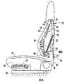
- Armrests 39are pivotally attached to sides of the back frame 23 , for pivotal movement between a lowered use position ( FIGS. 1-2 ) and a raised storage position ( FIG. 6 ). In the raised storage position, the armrests 39 are positioned adjacent a side of the back frame 23 and back shell 22 in locations where they do not interfere with lateral sliding entry into the seat 31 and back 21 .
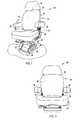
- the illustrated base 30includes apertured attachment flanges configured for attachment to a vehicle body. Further, the base 30 , the seat 31 , and the back frame 23 have suitable strength and construction for passing Federal Motor Vehicle Safety Standards (FMVSS), including impact and crashworthiness test requirements.
- FMVSSFederal Motor Vehicle Safety Standards
- the FMVSS standardsare very well known standards in the art of manufacturing vehicles, and are publicly available, such that a complete description of these standards is not necessary for an understanding of the present invention. It is well known that all modern passenger vehicles undergo crash testing as part of their approval process.
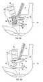
- this anglenot result in the lumbar section 26 being forced to take on an un-natural bend, such as the S-shaped bend illustrated in FIG. 3D .
- the angle of rotation for the pelvic section 50is faster (or slower) than a matched lengthening of the distance to the top pivot 24 , then the lumbar section 26 will be undesirably forced toward an unnatural and potentially uncomfortable double bend or uncontrolled shape (e.g. the shape shown in FIG. 3D ).
- a position of the pivots 52 - 55 and length of links 56 and 57must preferably be chosen to cooperate with each other to cause a closely controlled, constrained and predictable path of movement and angular rotation during movement and flexure of the back shell 22 .
- the thoracic section 46is rotated in an opposite angular direction toward a more vertically-oriented position generally aligned with the pelvic section 50 .
- Protruding stopscan also be put on the links 56 and 57 to abut and limit flexure of the lumbar section 26 .
- the links 56 and 57cooperate with the lumbar section 26 to cause the pelvic section 50 to be angled forwardly when in the up position, and cause the pelvic section 50 to be more vertically oriented when in the down position.
- This arrangementalso causes the lumbar section 26 to be more planar when in the down position ( FIG. 4 ).
Landscapes
- Engineering & Computer Science (AREA)
- Aviation & Aerospace Engineering (AREA)
- Transportation (AREA)
- Mechanical Engineering (AREA)
- Chair Legs, Seat Parts, And Backrests (AREA)
Abstract
Description
Claims (56)
Priority Applications (2)
| Application Number | Priority Date | Filing Date | Title |
|---|---|---|---|
| US10/865,082US7458637B2 (en) | 2004-06-10 | 2004-06-10 | Back construction with flexible lumbar |
| US11/048,673US7237841B2 (en) | 2004-06-10 | 2005-02-01 | Back construction with flexible lumbar |
Applications Claiming Priority (1)
| Application Number | Priority Date | Filing Date | Title |
|---|---|---|---|
| US10/865,082US7458637B2 (en) | 2004-06-10 | 2004-06-10 | Back construction with flexible lumbar |
Related Child Applications (1)
| Application Number | Title | Priority Date | Filing Date |
|---|---|---|---|
| US11/048,673Continuation-In-PartUS7237841B2 (en) | 2004-06-10 | 2005-02-01 | Back construction with flexible lumbar |
Publications (2)
| Publication Number | Publication Date |
|---|---|
| US20050275263A1 US20050275263A1 (en) | 2005-12-15 |
| US7458637B2true US7458637B2 (en) | 2008-12-02 |
Family
ID=35459792
Family Applications (1)
| Application Number | Title | Priority Date | Filing Date |
|---|---|---|---|
| US10/865,082Active2025-12-03US7458637B2 (en) | 2004-06-10 | 2004-06-10 | Back construction with flexible lumbar |
Country Status (1)
| Country | Link |
|---|---|
| US (1) | US7458637B2 (en) |
Cited By (18)
| Publication number | Priority date | Publication date | Assignee | Title |
|---|---|---|---|---|
| US20080079298A1 (en)* | 2006-09-29 | 2008-04-03 | Sunrise Medical Hhg Inc. | Shapeable wheelchair seatback assembly |
| US20090212615A1 (en)* | 2005-06-16 | 2009-08-27 | L&P Swiss Holding Company | Lumbar Support |
| US20090322133A1 (en)* | 2005-11-16 | 2009-12-31 | Masayuki Yamada | Seat Structure and Vehicle |
| DE202009000627U1 (en)* | 2009-01-20 | 2010-03-18 | Rücker GmbH | Adjustable lumbar support with eccentric mounting |
| US20100141001A1 (en)* | 2008-12-08 | 2010-06-10 | Matano Kunihiko | Lumbar support mechanism for vehicle |
| US20100164270A1 (en)* | 2006-07-07 | 2010-07-01 | Takeshi Akutsu | Vehicle seat |
| US20110193387A1 (en)* | 2008-10-10 | 2011-08-11 | Sidiz, Inc. | Tiltable chair |
| US20120007399A1 (en)* | 2010-07-12 | 2012-01-12 | Jaranson John W | Integrated lumbar for thin seat |
| US9004597B2 (en) | 2012-09-20 | 2015-04-14 | Steelcase Inc. | Chair back mechanism and control assembly |
| US20160325661A1 (en)* | 2015-05-05 | 2016-11-10 | Hamilton Sundstrand Corporation | Flexible lumbar support of aircraft seat |
| US9560917B2 (en) | 2014-11-26 | 2017-02-07 | Steelcase Inc. | Recline adjustment system for chair |
| US10322656B2 (en)* | 2017-07-28 | 2019-06-18 | GM Global Technology Operations LLC | Folding furniture piece system and method |
| US11129479B2 (en) | 2019-06-07 | 2021-09-28 | Michael J Snyder | Portable adjustable lumbar support and ergonomic chair |
| US11304528B2 (en) | 2012-09-20 | 2022-04-19 | Steelcase Inc. | Chair assembly with upholstery covering |
| US11440450B2 (en)* | 2019-09-11 | 2022-09-13 | Adient Us Llc | Thigh support and seat |
| US20230143122A1 (en)* | 2021-03-03 | 2023-05-11 | Ford Global Technologies, Llc | Seating assembly with displaceable panel |
| USD1072548S1 (en) | 2021-09-08 | 2025-04-29 | MillerKnoll, Inc. | Chair back |
| US12310513B2 (en) | 2021-09-08 | 2025-05-27 | MillerKnoll, Inc. | Seating structure |
Families Citing this family (28)
| Publication number | Priority date | Publication date | Assignee | Title |
|---|---|---|---|---|
| US7422287B2 (en)* | 2005-03-08 | 2008-09-09 | Steelcase Inc. | Seating with shape-changing back support frame |
| DE202005019654U1 (en)* | 2005-12-16 | 2007-04-26 | König + Neurath AG | Backrest and chair |
| EP1911374B1 (en)* | 2006-10-10 | 2010-08-11 | Provenda Marketing AG | Seat with ergonomic backrest |
| DE102007028052B4 (en)* | 2006-11-09 | 2020-09-24 | Adient Luxembourg Holding S.À R.L. | Vehicle seat |
| US7874619B2 (en)* | 2007-01-29 | 2011-01-25 | Allseating Corporation | Adjustable lumbar support for a chair back |
| DE102007026327A1 (en)* | 2007-06-06 | 2008-12-11 | Klöber GmbH | Flexible backrest for a work chair |
| DE102007044130A1 (en)* | 2007-09-15 | 2009-03-19 | König + Neurath AG | Backrest, in particular, of an office chair |
| US8727437B2 (en)* | 2008-06-27 | 2014-05-20 | Johnson Controls Technology Company | Actuator for crash activated head restraint |
| WO2010001253A1 (en)* | 2008-07-01 | 2010-01-07 | Johnson Controls Technology Company | Seat structure - cushion pan with a flexible hinge paddle |
| DE102008036130B4 (en)* | 2008-08-01 | 2014-12-18 | Sedus Stoll Ag | Tilting backrest |
| US20110059667A1 (en)* | 2009-09-09 | 2011-03-10 | Johnson Controls Technology Company | Cover with a spray on fabric |
| GB201005491D0 (en)* | 2010-03-31 | 2010-05-19 | Corcost Ltd | Corcost-SC010 |
| US9096147B2 (en)* | 2011-09-12 | 2015-08-04 | Faurecia Automotive Seating, Llc | Controllable comfort shell for vehicle seat |
| US20140246892A1 (en)* | 2011-10-04 | 2014-09-04 | L&P Swiss Holding Ag | Actuator arrangement for a seat and method of adjusting an adjustable component |
| DE202012007254U1 (en)* | 2012-07-26 | 2013-10-28 | Proflm Sp. Z.O.O. | Seating furniture, in particular office chair |
| CN105263367A (en)* | 2013-06-06 | 2016-01-20 | 株式会社伊藤喜 | Chair |
| US9357849B2 (en)* | 2013-10-10 | 2016-06-07 | James E. Grove | Dynamic lumbar support for a chair |
| US9192234B2 (en)* | 2014-01-28 | 2015-11-24 | James E. Grove | Progressively curved lumbar support for the back of a chair |
| US9596941B1 (en) | 2016-02-02 | 2017-03-21 | Office Master Inc. | Chair back with height and lumbar adjustment |
| NO342753B1 (en) | 2016-11-02 | 2018-08-06 | Img Group As | Motorized adjustable back support for recliner |
| TWM543007U (en)* | 2017-02-22 | 2017-06-11 | Xin-Hua Chen | Backrest structure |
| DE102017109367B4 (en)* | 2017-05-02 | 2025-03-20 | Component Engineering Services Gmbh | Lumbar support for one seat |
| US11253076B2 (en)* | 2019-02-05 | 2022-02-22 | Unchair LLC | Chair having open shoulder backrest |
| US10821861B2 (en)* | 2019-02-13 | 2020-11-03 | Ford Global Technologies, Llc | Articulating flexmat seat suspension |
| DE102020110623B4 (en)* | 2019-12-10 | 2024-08-22 | Adient Us Llc | VEHICLE SEAT |
| US11617444B2 (en) | 2020-03-02 | 2023-04-04 | Steelcase Inc. | Body support assembly and methods for the use and assembly thereof |
| US11812870B2 (en) | 2021-02-10 | 2023-11-14 | Steelcase Inc. | Body support structure |
| JP7644728B2 (en)* | 2022-02-22 | 2025-03-12 | 株式会社タチエス | Vehicle seat |
Citations (178)
| Publication number | Priority date | Publication date | Assignee | Title |
|---|---|---|---|---|
| US293833A (en) | 1884-02-19 | Chair | ||
| US362796A (en) | 1887-05-10 | William c | ||
| US1182854A (en)* | 1915-05-10 | 1916-05-09 | Albert J Coe | Flexible back adjustment for chairs. |
| US1590240A (en) | 1925-08-17 | 1926-06-29 | Gorton George | Chair for machine operators |
| FR708283A (en) | 1930-12-23 | 1931-07-22 | Improvements to recliners | |
| US2087254A (en) | 1935-05-16 | 1937-07-20 | Bassick Co | Tilting mechanism for chairs |
| US2139028A (en) | 1937-09-29 | 1938-12-06 | Elizabeth M Mensendicck | Seat |
| US2471024A (en) | 1946-10-04 | 1949-05-24 | Roy A Cramer | Chair with tilting back and automatically shiftable seat |
| US2492107A (en) | 1947-01-22 | 1949-12-20 | American Seating Co | Retracting type theater chair |
| US2627898A (en) | 1951-02-19 | 1953-02-10 | Jackson George Mcstay | Chair having an adjustable seat and back rest |
| US2712346A (en) | 1952-03-31 | 1955-07-05 | Goodyear Tire & Rubber | Adjustable seat |
| DE948544C (en) | 1953-03-02 | 1956-09-06 | Fritz Drabert Dr Ing | Sick bed made of metal tube |
| GB761805A (en) | 1953-03-02 | 1956-11-21 | Fritz Drabert | Improvements in reclining chairs |
| US2818911A (en) | 1954-11-05 | 1958-01-07 | Trumbull Dev Corp | Tiltable office chair |
| GB794138A (en) | 1955-12-20 | 1958-04-30 | Res Interests Ltd | Improvements in or relating to reclining chairs |
| US2843195A (en)* | 1956-01-25 | 1958-07-15 | Alvar E A Barvaeus | Self-adjusting back support |
| DE1044354B (en) | 1954-09-06 | 1958-11-20 | Fritz Drabert Dr Ing | Sick bed made of metal tube |
| US2894565A (en) | 1957-05-17 | 1959-07-14 | Hubert R Crane | Contouring back rest for motor vehicle seats |
| US3106423A (en) | 1960-11-21 | 1963-10-08 | Schwarz Johann | Back rest having an adjustable shaped element |
| US3369840A (en) | 1965-07-23 | 1968-02-20 | Dare Inglis Products Ltd | Chair tilting mechanism |
| US3540777A (en) | 1967-12-02 | 1970-11-17 | Mario Revelli De Beaumont | Chair for automotive vehicles with a displaceable back |
| US3565482A (en) | 1968-06-24 | 1971-02-23 | Leif Blodee | Adjustable contour chair |
| JPS4714408Y1 (en) | 1967-03-30 | 1972-05-24 | ||
| GB1278501A (en) | 1968-07-18 | 1972-06-21 | Air France | Improvements in and relating to tiltable chairs |
| US3762769A (en)* | 1970-12-30 | 1973-10-02 | Recaro Ag | Seat especially for motor vehicles |
| US3813148A (en) | 1972-04-17 | 1974-05-28 | H Kraus | Adjustable back support |
| US3877750A (en) | 1972-08-05 | 1975-04-15 | Porsche Ag | Reposing furniture |
| US3926286A (en) | 1973-02-05 | 1975-12-16 | Reell Precision Mfg | Spring grip clutch |
| US3934932A (en) | 1971-10-28 | 1976-01-27 | J.E. Ekornes Fabrikker A/S | Adjustable chair |
| US3938858A (en) | 1973-12-03 | 1976-02-17 | Fritz Drabert | Chair with adjustable backrest |
| US3948560A (en)* | 1975-03-31 | 1976-04-06 | Deere & Company | Seat having an adjustable back |
| US3948558A (en) | 1975-03-31 | 1976-04-06 | Deere & Company | Seat backrest having an adjustable lumbar support |
| US3982785A (en) | 1974-07-29 | 1976-09-28 | Center For Design Research And Development | Chair |
| US3989297A (en) | 1973-01-29 | 1976-11-02 | Fritz Kerstholt | Chair or couch with a movable back support |
| US4007962A (en) | 1975-01-10 | 1977-02-15 | Fehlbaum | Chair with adjustable back |
| US4054318A (en) | 1975-10-15 | 1977-10-18 | Lear Siegler, Inc. | Seat cushion mounting arrangement |
| US4083209A (en) | 1977-06-29 | 1978-04-11 | Stant Manufacturing Company, Inc. | Low profile threaded lock cap |
| US4084850A (en) | 1975-06-13 | 1978-04-18 | Center For Design Research And Development N.V. | Chair |
| US4099775A (en) | 1976-10-07 | 1978-07-11 | Hoover Ball And Bearing Company | Chair control with tilt lock |
| US4153293A (en)* | 1977-09-06 | 1979-05-08 | Nepsco, Inc. | Back rest |
| US4157203A (en) | 1977-05-09 | 1979-06-05 | Center For Design Research And Development N.V. | Articulated double back for chairs |
| US4181357A (en) | 1978-03-20 | 1980-01-01 | Milsco Manufacturing Company | Seat backrest tilt and height adjustment means |
| US4226473A (en) | 1978-03-13 | 1980-10-07 | Pontiac Furniture Industries, Inc. | Reclining chair |
| US4309206A (en) | 1977-04-01 | 1982-01-05 | Skw Trostberg Aktiengesellschaft | Process for the production of odorless prilled urea-dicyandiamide fertilizers |
| EP0043242A1 (en) | 1980-06-26 | 1982-01-06 | Labofa A/S | Adjustable office chair or working chair with position indicator |
| US4313637A (en)* | 1978-11-18 | 1982-02-02 | Uop Inc. | Seat having a movable lumbar support |
| US4314728A (en) | 1980-05-01 | 1982-02-09 | Steelcase Inc. | Chair control |
| US4316632A (en) | 1978-09-08 | 1982-02-23 | Protoned Bv | Ergonomic chair |
| US4333683A (en) | 1978-12-04 | 1982-06-08 | Center For Design Research And Development N.V. | Chair with automatically adjustable tilting back |
| US4380352A (en) | 1979-06-11 | 1983-04-19 | Knoll International, Inc. | Reclining chair |
| US4449752A (en) | 1979-03-06 | 1984-05-22 | Toyota Jidosha Kogyo Kabushiki Kaisha | Vehicle seat position control mechanism with neutral memory |
| US4452486A (en) | 1980-09-24 | 1984-06-05 | Otto Zapf | Chair type furniture |
| US4465317A (en) | 1980-01-26 | 1984-08-14 | Johann Schwarz | Mechanism for adjusting a lumbar support of a back of a seat or the like |
| US4502728A (en) | 1982-10-08 | 1985-03-05 | Nepsco, Inc. | Portable seat and back rest |
| US4521053A (en) | 1981-06-23 | 1985-06-04 | Gispen+Staalmeubel B.V. | Chair |
| US4544204A (en) | 1981-11-11 | 1985-10-01 | Keiper Automobiltechnik Gmbh & Co. Kg | Back frame for seat, particularly for power vehicle seat |
| US4585272A (en) | 1982-10-22 | 1986-04-29 | Castelli S.P.A. | Chair having a back comprising a plurality of articulated segments |
| US4595237A (en) | 1984-05-11 | 1986-06-17 | Haworth, Inc. | Actuating control for seat height adjustment mechanism |
| US4621866A (en) | 1985-05-17 | 1986-11-11 | Giuseppe Zani | Armchair structure having an adjustable anatomical configuration |
| US4621864A (en) | 1984-12-13 | 1986-11-11 | Milsco Manufacturing Company | Tiltable arm rest assembly and mounting and operating means therefor |
| US4632454A (en) | 1983-11-09 | 1986-12-30 | Ab Volvo | Vehicle seat intended, for example, for such automobile vehicles as cars, trains and airplanes |
| US4638679A (en) | 1983-06-11 | 1987-01-27 | Ford Motor Company | Adjusting mechanism for a Bowden cable |
| US4641884A (en) | 1985-02-21 | 1987-02-10 | Honda Giken Kogyo Kabushiki Kaisha | Seat for vehicles |
| WO1987000738A1 (en) | 1985-07-30 | 1987-02-12 | Hyung Sik Park | A chair adjustable to optimum standard height |
| US4685730A (en) | 1984-12-21 | 1987-08-11 | Etablissements Linguanotto | Seat, especially work seat, with several positions |
| US4703974A (en) | 1984-10-23 | 1987-11-03 | Protoned B.V. | Seat furniture |
| US4709963A (en) | 1986-12-12 | 1987-12-01 | Milsco Manufacturing Company | Adjustable office chair |
| US4720142A (en) | 1986-04-10 | 1988-01-19 | Steelcase Inc. | Variable back stop |
| US4730871A (en) | 1986-08-14 | 1988-03-15 | Nepsco, Inc. | Adjustable back rest |
| US4763950A (en) | 1986-01-07 | 1988-08-16 | Provenda Marketing Ag | Tilting chair, especially office chair |
| US4776633A (en) | 1986-04-10 | 1988-10-11 | Steelcase Inc. | Integrated chair and control |
| US4779925A (en) | 1986-05-15 | 1988-10-25 | Eberhard Heinzel | Height-adjustable swivel chair equipped with gas-pressure spring, especially office chair or office armchair |
| US4834453A (en) | 1986-09-08 | 1989-05-30 | Girsberger Holding Ag | Swivel chair |
| US4834454A (en) | 1987-05-15 | 1989-05-30 | Faultless-Doerner Manufacturing Inc. | Office chair with tiltable seat and back |
| US4842333A (en) | 1987-08-14 | 1989-06-27 | Grammer Sitzsysteme Gmbh | Seat |
| US4848837A (en) | 1986-10-15 | 1989-07-18 | Voelkle Rolf | Chair having a pelvis-hip support adjustable relative to a front seat portion |
| US4854641A (en) | 1989-01-23 | 1989-08-08 | Reineman Richard G | Adjustable chair |
| US4861108A (en) | 1988-06-07 | 1989-08-29 | American Seating Company | Auditorium seat |
| US4878710A (en) | 1988-07-11 | 1989-11-07 | Super Sagless Corporation | Wall proximity chair |
| US4880271A (en) | 1987-12-28 | 1989-11-14 | Wickes Manufacturing Company | Adjustable lumbar support |
| US4889384A (en) | 1988-07-10 | 1989-12-26 | Leggett & Platt, Incorporated | Knee-action chair control |
| US4896918A (en) | 1987-10-20 | 1990-01-30 | Aisin Seiki Kabushiki Kaisha | Lumbar support regulating apparatus |
| US4906045A (en) | 1989-03-20 | 1990-03-06 | The Shaw-Walker Company | Chair control for a pedestal chair having a knee-tilt seat |
| US4913303A (en) | 1987-06-16 | 1990-04-03 | Stant Inc. | Liquid splash control fuel cap |
| US4915449A (en) | 1988-05-18 | 1990-04-10 | Pro-Cord S.R.L. | Chair with a pivoting seat |
| US4948198A (en) | 1988-10-14 | 1990-08-14 | Leggett & Platt, Incorporated | Knee-tilt chair control |
| US4951995A (en) | 1989-10-10 | 1990-08-28 | Steelcase Inc. | Arm height adjustment mechanism for a chair |
| US4966413A (en) | 1989-08-17 | 1990-10-30 | Palarski Timothy D | Articulated relaxation chair |
| US4968093A (en) | 1987-10-16 | 1990-11-06 | Fiat Auto S.P.A. | Adjustable backrest for the seats of vehicles, particularly cars |
| US4981326A (en) | 1987-09-22 | 1991-01-01 | Steelcase Strafor | Ergonomic chair |
| US4984846A (en) | 1987-10-19 | 1991-01-15 | J. E. Ekornes A/S | Arrangement in an adjustable chair |
| US5009466A (en) | 1988-04-25 | 1991-04-23 | Perry Charles O | Reclining chair |
| US5027022A (en) | 1989-07-14 | 1991-06-25 | Tokai Rika Denki Seisakusho Co. | Reverse rotation preventing mechanism for synchronous motors |
| US5029940A (en) | 1990-01-16 | 1991-07-09 | Westinghouse Electric Corporation | Chair tilt and chair height control apparatus |
| US5037116A (en) | 1988-10-21 | 1991-08-06 | Simon Desanta | Foldable chair |
| US5039163A (en) | 1988-09-14 | 1991-08-13 | Shelby Williams Industries, Inc. | Reinforced flexible backrest assembly for a chair |
| US5044693A (en) | 1989-10-31 | 1991-09-03 | Tachi-S Co., Ltd. | Seat back structure of an automotive seat |
| US5050930A (en) | 1989-08-04 | 1991-09-24 | Wilhelm Schuster | Lordosis-support backrest for a vehicle seat |
| DE9109959U1 (en) | 1990-08-16 | 1991-10-10 | Hartman Groep B.V., Enschede | Folding furniture with adjustable seat |
| US5056862A (en) | 1990-07-03 | 1991-10-15 | Action Industries, Inc. | Recessed lever actuator for recliner mechanism |
| US5062676A (en) | 1990-04-16 | 1991-11-05 | Mars Suzanne P | Adjustable chair |
| US5087098A (en) | 1990-09-25 | 1992-02-11 | Tachi-S Co., Ltd. | Lumbar support device |
| US5088790A (en)* | 1990-05-21 | 1992-02-18 | Lear Seating Corporation | Adjustable lumbar support mechanism for a vehicular seat |
| US5100200A (en) | 1987-12-29 | 1992-03-31 | Roeder Gmbh | Chair, in particular work or office chair |
| US5100201A (en) | 1990-09-21 | 1992-03-31 | J.G. Furniture Systems Inc. | Passive ergonomic work chair |
| US5102196A (en) | 1988-08-31 | 1992-04-07 | Kokuyo Co., Ltd. | Chair provided with a backrest |
| US5106157A (en) | 1989-03-01 | 1992-04-21 | Herman Miller, Inc. | Chair height and tilt adjustment mechanisms |
| US5107720A (en) | 1991-07-24 | 1992-04-28 | Plastic Industries, Inc. | Device for actuating a remotely positioned latch |
| US5110003A (en) | 1990-06-28 | 1992-05-05 | Stant Inc. | Torque-override cap |
| US5112108A (en) | 1990-07-09 | 1992-05-12 | Otto Zapf | Seating furniture |
| US5120109A (en) | 1988-07-25 | 1992-06-09 | Sicam S.P.A. | Motor vehicle seat |
| EP0516341A1 (en) | 1991-05-21 | 1992-12-02 | Ashfield Engineering Company Wexford Limited | A chair tilting mechanism |
| US5193880A (en) | 1987-12-29 | 1993-03-16 | Roeder Gmbh | Chair, in particular work or office chair |
| US5217278A (en) | 1991-03-13 | 1993-06-08 | Findlay Industries, Inc. | Mechanism for providing adjustable lumbar support in a seat |
| JPH05184432A (en) | 1991-10-22 | 1993-07-27 | Itoki Crebio Corp | Inclination controller of chair |
| JPH05207920A (en)* | 1992-01-30 | 1993-08-20 | Shiroki Corp | Seat back device and lumbar support plate |
| US5240308A (en) | 1983-11-09 | 1993-08-31 | Goldstein Glenn A | Ergonomic adjustable chair and method |
| US5249839A (en) | 1991-11-12 | 1993-10-05 | Steelcase Inc. | Split back chair |
| WO1993025121A1 (en) | 1992-06-15 | 1993-12-23 | Herman Miller, Inc. | Office chair |
| US5277475A (en) | 1992-07-15 | 1994-01-11 | Engineered Components, Inc. | One piece back support for a chair |
| US5282670A (en) | 1992-04-20 | 1994-02-01 | Steelcase Inc. | Cable actuated variable stop mechanism |
| US5299851A (en) | 1993-05-19 | 1994-04-05 | Lin Kuen Yuan | Adjustable cushion assembly for a chair |
| US5302002A (en) | 1990-09-28 | 1994-04-12 | Shiroki Corporation | Hip supporting apparatus of seat |
| US5308145A (en) | 1992-02-12 | 1994-05-03 | Kimball International Marketing, Inc. | Reclining chair |
| US5318346A (en) | 1991-05-30 | 1994-06-07 | Steelcase Inc. | Chair with zero front rise control |
| US5320410A (en) | 1992-01-14 | 1994-06-14 | Steelcase Inc. | Chair control |
| US5328242A (en) | 1992-03-18 | 1994-07-12 | Steelcase Inc. | Chair with back lock |
| US5354120A (en) | 1991-10-31 | 1994-10-11 | Voelkle Rolf | Reclining chair |
| US5364162A (en) | 1991-03-01 | 1994-11-15 | Roho, Inc. | Backrest assembly for a wheelchair |
| US5366274A (en) | 1989-12-29 | 1994-11-22 | Wilkhahn Wilkening + Hahne Gmbh + Co. | Synchronous adjusting device for office chairs or the like |
| US5405188A (en) | 1993-10-21 | 1995-04-11 | Mdt Corporation | Mechanical chair |
| US5423593A (en)* | 1994-03-10 | 1995-06-13 | Tachi-S, Co., Ltd. | Lumbar support device |
| US5447356A (en) | 1990-05-01 | 1995-09-05 | B.V. Linido | Chair for disabled persons |
| US5449086A (en) | 1993-10-18 | 1995-09-12 | Stant Manufacturing Inc. | Delayed actuation fuel cap |
| US5452868A (en) | 1991-11-27 | 1995-09-26 | Futureflite Corporation | Adjustable lumbar support with remote push-button control |
| US5460427A (en) | 1990-10-29 | 1995-10-24 | Serber; Hector | Seat assembly and method |
| EP0680713A1 (en) | 1994-04-21 | 1995-11-08 | Zitmeubelen Jori, N.V. | Mechanism for a relaxation chair |
| US5472261A (en) | 1990-10-12 | 1995-12-05 | Ekornes Fabrikker As J E | Arrangement in a recline chair |
| US5474360A (en) | 1993-10-06 | 1995-12-12 | Chang; Chung L. | Seatback recliner mechanism |
| US5505520A (en) | 1994-11-03 | 1996-04-09 | Ford Motor Company | Passenger seat with adjustable lumbar support |
| US5518294A (en) | 1993-04-05 | 1996-05-21 | Ligon Brothers Manufacturing Company | Variable apex back support |
| US5529201A (en) | 1994-05-20 | 1996-06-25 | Stant Manufacturing Inc. | Cam-on filler neck cap |
| US5564783A (en) | 1993-07-22 | 1996-10-15 | Duphin Entwicklungs-U. Beteiligungs-Gmbh | Chair, in particular office chair |
| US5573302A (en) | 1994-11-08 | 1996-11-12 | Harrison; Patrick N. | Lower back support |
| US5577807A (en) | 1994-06-09 | 1996-11-26 | Steelcase Inc. | Adjustable chair actuator |
| US5582459A (en) | 1993-09-30 | 1996-12-10 | Itoki Crebio Corporation | Chair having tiltable seat back |
| US5590932A (en) | 1994-11-07 | 1997-01-07 | Fisher Dynamics Corporation | Anti-chuck seat recliner |
| US5597203A (en) | 1994-06-14 | 1997-01-28 | Board Of Trustees Operating Michigan State University | Seat with biomechanical articulation |
| US5630647A (en) | 1995-02-17 | 1997-05-20 | Steelcase Inc. | Tension adjustment mechanism for chairs |
| US5636898A (en) | 1994-04-15 | 1997-06-10 | Burns Aerospace Corporation | Seat with recline linkage |
| US5651584A (en) | 1995-04-24 | 1997-07-29 | L & P Property Management Company | Lumbar support structure for automotive vehicle |
| US5660439A (en) | 1995-01-04 | 1997-08-26 | Unwalla; Jamshed | Integrated seat and back and mechanisms for chairs |
| US5791733A (en) | 1996-02-09 | 1998-08-11 | Knoll, Inc. | Adjustable lumbar support |
| US5842743A (en)* | 1992-10-09 | 1998-12-01 | La-Z-Boy Incorporated | Sofa bridge |
| US5860701A (en) | 1996-09-06 | 1999-01-19 | Thomas Jungjohann | Seating furniture component or the like with a coupled backrest and seat adjustment |
| US5868467A (en) | 1996-08-28 | 1999-02-09 | Thomas Jungjohann | Seating furniture component or the like with a coupled backrest and seat adjustment |
| US5871258A (en) | 1997-10-24 | 1999-02-16 | Steelcase Inc. | Chair with novel seat construction |
| US5915788A (en) | 1996-04-22 | 1999-06-29 | Steelcase Inc. | Multi-function control for chair |
| US5947558A (en)* | 1997-06-19 | 1999-09-07 | Aisin Seiki Kabushiki Kaisha | Lumbar support device |
| US6135559A (en) | 1997-07-31 | 2000-10-24 | Hickory Springs Manufacturing Co. | Seat back reclining mechanism adaptable to chairs with stationary or movable seats |
| US6250715B1 (en) | 1998-01-21 | 2001-06-26 | Herman Miller, Inc. | Chair |
| US20020003366A1 (en) | 2000-04-27 | 2002-01-10 | Faurecia Sieges D'automobile S.A. | Seat pan producing a massaging effect, in particular for automobile vehicle |
| US20020047297A1 (en) | 2000-04-04 | 2002-04-25 | Alberto Longhi | Adaptable seat |
| US6412869B1 (en) | 1999-05-27 | 2002-07-02 | Steelcase Development Corporation | Nestable synchrotilt chair |
| US20020130540A1 (en) | 1997-09-24 | 2002-09-19 | Rajasingham Arjuna Indraeswaran | Easy ejector seat with skeletal crash safety beam |
| US6474737B1 (en) | 1999-07-30 | 2002-11-05 | Bertrand Faure Equipments Sa | Variable configuration automobile vehicle seat |
| US20020163233A1 (en) | 2001-05-03 | 2002-11-07 | Craft Raymond E. | Article of furniture having a support member with an adjustable contour |
| US20020180248A1 (en) | 2000-10-16 | 2002-12-05 | Yojiro Kinoshita | Chair |
| US6523898B1 (en) | 1999-06-17 | 2003-02-25 | Steelcase Development Corporation | Chair construction |
| US20030071500A1 (en) | 2001-09-15 | 2003-04-17 | Emil Dinkel | Padding for seats, in particular vehicle seats |
| US20030094841A1 (en) | 2001-11-16 | 2003-05-22 | Mcmillen Robert | Method and apparatus for lumbar support with integrated actuator housing |
| US20030137171A1 (en) | 2001-12-14 | 2003-07-24 | Deimen Michael L. | Chair with conforming seat |
| US6609755B2 (en) | 2001-06-15 | 2003-08-26 | Hon Technology Inc. | Ergonomic chair |
| US6616228B2 (en)* | 2001-06-20 | 2003-09-09 | Steelcase Development Corporation | Compliant back for seating unit |
| US20030189367A1 (en) | 2002-04-07 | 2003-10-09 | Christian Erker | Bucket seat with inclination-profile adjusting mechanism |
| US20030214166A1 (en) | 2002-05-15 | 2003-11-20 | Schambre John E. | Adjustable seatback assembly |
| US6679553B2 (en) | 2002-03-01 | 2004-01-20 | Steelcase Development Corporation | Energy system assembly for seating unit |
| US6709058B1 (en) | 1999-04-09 | 2004-03-23 | Humanscale Corp. | Ergonomic chair |
Family Cites Families (1)
| Publication number | Priority date | Publication date | Assignee | Title |
|---|---|---|---|---|
| US2497024A (en)* | 1945-10-05 | 1950-02-07 | John H Billman | Electrochemical preparation of alpha-amino-n-butyric acid and n-benzoyl derivative |
- 2004
- 2004-06-10USUS10/865,082patent/US7458637B2/enactiveActive
Patent Citations (191)
| Publication number | Priority date | Publication date | Assignee | Title |
|---|---|---|---|---|
| US293833A (en) | 1884-02-19 | Chair | ||
| US362796A (en) | 1887-05-10 | William c | ||
| US1182854A (en)* | 1915-05-10 | 1916-05-09 | Albert J Coe | Flexible back adjustment for chairs. |
| US1590240A (en) | 1925-08-17 | 1926-06-29 | Gorton George | Chair for machine operators |
| FR708283A (en) | 1930-12-23 | 1931-07-22 | Improvements to recliners | |
| US2087254A (en) | 1935-05-16 | 1937-07-20 | Bassick Co | Tilting mechanism for chairs |
| US2139028A (en) | 1937-09-29 | 1938-12-06 | Elizabeth M Mensendicck | Seat |
| US2471024A (en) | 1946-10-04 | 1949-05-24 | Roy A Cramer | Chair with tilting back and automatically shiftable seat |
| US2492107A (en) | 1947-01-22 | 1949-12-20 | American Seating Co | Retracting type theater chair |
| US2627898A (en) | 1951-02-19 | 1953-02-10 | Jackson George Mcstay | Chair having an adjustable seat and back rest |
| US2712346A (en) | 1952-03-31 | 1955-07-05 | Goodyear Tire & Rubber | Adjustable seat |
| GB761805A (en) | 1953-03-02 | 1956-11-21 | Fritz Drabert | Improvements in reclining chairs |
| DE948544C (en) | 1953-03-02 | 1956-09-06 | Fritz Drabert Dr Ing | Sick bed made of metal tube |
| DE1044354B (en) | 1954-09-06 | 1958-11-20 | Fritz Drabert Dr Ing | Sick bed made of metal tube |
| US2818911A (en) | 1954-11-05 | 1958-01-07 | Trumbull Dev Corp | Tiltable office chair |
| GB794138A (en) | 1955-12-20 | 1958-04-30 | Res Interests Ltd | Improvements in or relating to reclining chairs |
| US2843195A (en)* | 1956-01-25 | 1958-07-15 | Alvar E A Barvaeus | Self-adjusting back support |
| US2894565A (en) | 1957-05-17 | 1959-07-14 | Hubert R Crane | Contouring back rest for motor vehicle seats |
| US3106423A (en) | 1960-11-21 | 1963-10-08 | Schwarz Johann | Back rest having an adjustable shaped element |
| US3369840A (en) | 1965-07-23 | 1968-02-20 | Dare Inglis Products Ltd | Chair tilting mechanism |
| JPS4714408Y1 (en) | 1967-03-30 | 1972-05-24 | ||
| US3540777A (en) | 1967-12-02 | 1970-11-17 | Mario Revelli De Beaumont | Chair for automotive vehicles with a displaceable back |
| US3565482A (en) | 1968-06-24 | 1971-02-23 | Leif Blodee | Adjustable contour chair |
| GB1278501A (en) | 1968-07-18 | 1972-06-21 | Air France | Improvements in and relating to tiltable chairs |
| US3762769A (en)* | 1970-12-30 | 1973-10-02 | Recaro Ag | Seat especially for motor vehicles |
| US3934932A (en) | 1971-10-28 | 1976-01-27 | J.E. Ekornes Fabrikker A/S | Adjustable chair |
| US3813148A (en) | 1972-04-17 | 1974-05-28 | H Kraus | Adjustable back support |
| US3877750A (en) | 1972-08-05 | 1975-04-15 | Porsche Ag | Reposing furniture |
| US3989297A (en) | 1973-01-29 | 1976-11-02 | Fritz Kerstholt | Chair or couch with a movable back support |
| US3926286A (en) | 1973-02-05 | 1975-12-16 | Reell Precision Mfg | Spring grip clutch |
| US3938858A (en) | 1973-12-03 | 1976-02-17 | Fritz Drabert | Chair with adjustable backrest |
| US3982785A (en) | 1974-07-29 | 1976-09-28 | Center For Design Research And Development | Chair |
| US4007962A (en) | 1975-01-10 | 1977-02-15 | Fehlbaum | Chair with adjustable back |
| US3948560A (en)* | 1975-03-31 | 1976-04-06 | Deere & Company | Seat having an adjustable back |
| US3948558A (en) | 1975-03-31 | 1976-04-06 | Deere & Company | Seat backrest having an adjustable lumbar support |
| US4084850A (en) | 1975-06-13 | 1978-04-18 | Center For Design Research And Development N.V. | Chair |
| US4054318A (en) | 1975-10-15 | 1977-10-18 | Lear Siegler, Inc. | Seat cushion mounting arrangement |
| US4099775A (en) | 1976-10-07 | 1978-07-11 | Hoover Ball And Bearing Company | Chair control with tilt lock |
| US4309206A (en) | 1977-04-01 | 1982-01-05 | Skw Trostberg Aktiengesellschaft | Process for the production of odorless prilled urea-dicyandiamide fertilizers |
| US4157203A (en) | 1977-05-09 | 1979-06-05 | Center For Design Research And Development N.V. | Articulated double back for chairs |
| US4083209A (en) | 1977-06-29 | 1978-04-11 | Stant Manufacturing Company, Inc. | Low profile threaded lock cap |
| US4153293A (en)* | 1977-09-06 | 1979-05-08 | Nepsco, Inc. | Back rest |
| US4226473A (en) | 1978-03-13 | 1980-10-07 | Pontiac Furniture Industries, Inc. | Reclining chair |
| US4181357A (en) | 1978-03-20 | 1980-01-01 | Milsco Manufacturing Company | Seat backrest tilt and height adjustment means |
| US4316632A (en) | 1978-09-08 | 1982-02-23 | Protoned Bv | Ergonomic chair |
| US4313637A (en)* | 1978-11-18 | 1982-02-02 | Uop Inc. | Seat having a movable lumbar support |
| US4333683A (en) | 1978-12-04 | 1982-06-08 | Center For Design Research And Development N.V. | Chair with automatically adjustable tilting back |
| US4449752A (en) | 1979-03-06 | 1984-05-22 | Toyota Jidosha Kogyo Kabushiki Kaisha | Vehicle seat position control mechanism with neutral memory |
| US4380352A (en) | 1979-06-11 | 1983-04-19 | Knoll International, Inc. | Reclining chair |
| US4465317A (en) | 1980-01-26 | 1984-08-14 | Johann Schwarz | Mechanism for adjusting a lumbar support of a back of a seat or the like |
| US4390206A (en) | 1980-05-01 | 1983-06-28 | Steelcase, Incorporated | Synchrotilt chair control |
| US4314728A (en) | 1980-05-01 | 1982-02-09 | Steelcase Inc. | Chair control |
| EP0043242A1 (en) | 1980-06-26 | 1982-01-06 | Labofa A/S | Adjustable office chair or working chair with position indicator |
| US4452486A (en) | 1980-09-24 | 1984-06-05 | Otto Zapf | Chair type furniture |
| US4521053A (en) | 1981-06-23 | 1985-06-04 | Gispen+Staalmeubel B.V. | Chair |
| US4544204A (en) | 1981-11-11 | 1985-10-01 | Keiper Automobiltechnik Gmbh & Co. Kg | Back frame for seat, particularly for power vehicle seat |
| US4502728A (en) | 1982-10-08 | 1985-03-05 | Nepsco, Inc. | Portable seat and back rest |
| US4585272A (en) | 1982-10-22 | 1986-04-29 | Castelli S.P.A. | Chair having a back comprising a plurality of articulated segments |
| US4638679A (en) | 1983-06-11 | 1987-01-27 | Ford Motor Company | Adjusting mechanism for a Bowden cable |
| US4632454A (en) | 1983-11-09 | 1986-12-30 | Ab Volvo | Vehicle seat intended, for example, for such automobile vehicles as cars, trains and airplanes |
| US5240308A (en) | 1983-11-09 | 1993-08-31 | Goldstein Glenn A | Ergonomic adjustable chair and method |
| US4595237A (en) | 1984-05-11 | 1986-06-17 | Haworth, Inc. | Actuating control for seat height adjustment mechanism |
| US4703974A (en) | 1984-10-23 | 1987-11-03 | Protoned B.V. | Seat furniture |
| US4621864A (en) | 1984-12-13 | 1986-11-11 | Milsco Manufacturing Company | Tiltable arm rest assembly and mounting and operating means therefor |
| US4685730A (en) | 1984-12-21 | 1987-08-11 | Etablissements Linguanotto | Seat, especially work seat, with several positions |
| US4641884A (en) | 1985-02-21 | 1987-02-10 | Honda Giken Kogyo Kabushiki Kaisha | Seat for vehicles |
| US4621866A (en) | 1985-05-17 | 1986-11-11 | Giuseppe Zani | Armchair structure having an adjustable anatomical configuration |
| WO1987000738A1 (en) | 1985-07-30 | 1987-02-12 | Hyung Sik Park | A chair adjustable to optimum standard height |
| US4763950A (en) | 1986-01-07 | 1988-08-16 | Provenda Marketing Ag | Tilting chair, especially office chair |
| US5487591A (en) | 1986-04-10 | 1996-01-30 | Steelcase, Inc. | Back shell with selective stiffening |
| US4776633A (en) | 1986-04-10 | 1988-10-11 | Steelcase Inc. | Integrated chair and control |
| US5611598A (en) | 1986-04-10 | 1997-03-18 | Steelcase Inc. | Chair having back shell with selective stiffening |
| US4720142A (en) | 1986-04-10 | 1988-01-19 | Steelcase Inc. | Variable back stop |
| US4779925A (en) | 1986-05-15 | 1988-10-25 | Eberhard Heinzel | Height-adjustable swivel chair equipped with gas-pressure spring, especially office chair or office armchair |
| US4730871A (en) | 1986-08-14 | 1988-03-15 | Nepsco, Inc. | Adjustable back rest |
| US4834453A (en) | 1986-09-08 | 1989-05-30 | Girsberger Holding Ag | Swivel chair |
| US4848837A (en) | 1986-10-15 | 1989-07-18 | Voelkle Rolf | Chair having a pelvis-hip support adjustable relative to a front seat portion |
| US4709963A (en) | 1986-12-12 | 1987-12-01 | Milsco Manufacturing Company | Adjustable office chair |
| US4834454A (en) | 1987-05-15 | 1989-05-30 | Faultless-Doerner Manufacturing Inc. | Office chair with tiltable seat and back |
| US4913303A (en) | 1987-06-16 | 1990-04-03 | Stant Inc. | Liquid splash control fuel cap |
| US4842333A (en) | 1987-08-14 | 1989-06-27 | Grammer Sitzsysteme Gmbh | Seat |
| US4981326A (en) | 1987-09-22 | 1991-01-01 | Steelcase Strafor | Ergonomic chair |
| US4968093A (en) | 1987-10-16 | 1990-11-06 | Fiat Auto S.P.A. | Adjustable backrest for the seats of vehicles, particularly cars |
| US4984846A (en) | 1987-10-19 | 1991-01-15 | J. E. Ekornes A/S | Arrangement in an adjustable chair |
| US4896918A (en) | 1987-10-20 | 1990-01-30 | Aisin Seiki Kabushiki Kaisha | Lumbar support regulating apparatus |
| US4880271A (en) | 1987-12-28 | 1989-11-14 | Wickes Manufacturing Company | Adjustable lumbar support |
| US5100200A (en) | 1987-12-29 | 1992-03-31 | Roeder Gmbh | Chair, in particular work or office chair |
| US5193880A (en) | 1987-12-29 | 1993-03-16 | Roeder Gmbh | Chair, in particular work or office chair |
| US5009466A (en) | 1988-04-25 | 1991-04-23 | Perry Charles O | Reclining chair |
| US4915449A (en) | 1988-05-18 | 1990-04-10 | Pro-Cord S.R.L. | Chair with a pivoting seat |
| US4861108A (en) | 1988-06-07 | 1989-08-29 | American Seating Company | Auditorium seat |
| US4889384A (en) | 1988-07-10 | 1989-12-26 | Leggett & Platt, Incorporated | Knee-action chair control |
| US4878710A (en) | 1988-07-11 | 1989-11-07 | Super Sagless Corporation | Wall proximity chair |
| US5120109A (en) | 1988-07-25 | 1992-06-09 | Sicam S.P.A. | Motor vehicle seat |
| US5102196A (en) | 1988-08-31 | 1992-04-07 | Kokuyo Co., Ltd. | Chair provided with a backrest |
| US5039163A (en) | 1988-09-14 | 1991-08-13 | Shelby Williams Industries, Inc. | Reinforced flexible backrest assembly for a chair |
| US4948198A (en) | 1988-10-14 | 1990-08-14 | Leggett & Platt, Incorporated | Knee-tilt chair control |
| US5037116A (en) | 1988-10-21 | 1991-08-06 | Simon Desanta | Foldable chair |
| US4854641A (en) | 1989-01-23 | 1989-08-08 | Reineman Richard G | Adjustable chair |
| US5192114A (en) | 1989-03-01 | 1993-03-09 | Herman Miller, Inc. | Tilt adjustment control for a chair |
| US5106157A (en) | 1989-03-01 | 1992-04-21 | Herman Miller, Inc. | Chair height and tilt adjustment mechanisms |
| US4906045A (en) | 1989-03-20 | 1990-03-06 | The Shaw-Walker Company | Chair control for a pedestal chair having a knee-tilt seat |
| US5027022A (en) | 1989-07-14 | 1991-06-25 | Tokai Rika Denki Seisakusho Co. | Reverse rotation preventing mechanism for synchronous motors |
| US5050930A (en) | 1989-08-04 | 1991-09-24 | Wilhelm Schuster | Lordosis-support backrest for a vehicle seat |
| US4966413A (en) | 1989-08-17 | 1990-10-30 | Palarski Timothy D | Articulated relaxation chair |
| US4951995A (en) | 1989-10-10 | 1990-08-28 | Steelcase Inc. | Arm height adjustment mechanism for a chair |
| US5044693A (en) | 1989-10-31 | 1991-09-03 | Tachi-S Co., Ltd. | Seat back structure of an automotive seat |
| US5366274A (en) | 1989-12-29 | 1994-11-22 | Wilkhahn Wilkening + Hahne Gmbh + Co. | Synchronous adjusting device for office chairs or the like |
| US5029940A (en) | 1990-01-16 | 1991-07-09 | Westinghouse Electric Corporation | Chair tilt and chair height control apparatus |
| US5062676A (en) | 1990-04-16 | 1991-11-05 | Mars Suzanne P | Adjustable chair |
| US5447356A (en) | 1990-05-01 | 1995-09-05 | B.V. Linido | Chair for disabled persons |
| US5088790A (en)* | 1990-05-21 | 1992-02-18 | Lear Seating Corporation | Adjustable lumbar support mechanism for a vehicular seat |
| US5110003A (en) | 1990-06-28 | 1992-05-05 | Stant Inc. | Torque-override cap |
| US5056862A (en) | 1990-07-03 | 1991-10-15 | Action Industries, Inc. | Recessed lever actuator for recliner mechanism |
| US5112108A (en) | 1990-07-09 | 1992-05-12 | Otto Zapf | Seating furniture |
| DE9109959U1 (en) | 1990-08-16 | 1991-10-10 | Hartman Groep B.V., Enschede | Folding furniture with adjustable seat |
| US5100201A (en) | 1990-09-21 | 1992-03-31 | J.G. Furniture Systems Inc. | Passive ergonomic work chair |
| US5087098A (en) | 1990-09-25 | 1992-02-11 | Tachi-S Co., Ltd. | Lumbar support device |
| US5302002A (en) | 1990-09-28 | 1994-04-12 | Shiroki Corporation | Hip supporting apparatus of seat |
| US5472261A (en) | 1990-10-12 | 1995-12-05 | Ekornes Fabrikker As J E | Arrangement in a recline chair |
| US5460427A (en) | 1990-10-29 | 1995-10-24 | Serber; Hector | Seat assembly and method |
| US5364162A (en) | 1991-03-01 | 1994-11-15 | Roho, Inc. | Backrest assembly for a wheelchair |
| US5217278A (en) | 1991-03-13 | 1993-06-08 | Findlay Industries, Inc. | Mechanism for providing adjustable lumbar support in a seat |
| EP0516341A1 (en) | 1991-05-21 | 1992-12-02 | Ashfield Engineering Company Wexford Limited | A chair tilting mechanism |
| US5540481A (en) | 1991-05-30 | 1996-07-30 | Steelcase, Inc. | Chair with zero front rise control |
| US5318346A (en) | 1991-05-30 | 1994-06-07 | Steelcase Inc. | Chair with zero front rise control |
| US5107720A (en) | 1991-07-24 | 1992-04-28 | Plastic Industries, Inc. | Device for actuating a remotely positioned latch |
| JPH05184432A (en) | 1991-10-22 | 1993-07-27 | Itoki Crebio Corp | Inclination controller of chair |
| US5354120A (en) | 1991-10-31 | 1994-10-11 | Voelkle Rolf | Reclining chair |
| US5249839A (en) | 1991-11-12 | 1993-10-05 | Steelcase Inc. | Split back chair |
| US5385388A (en) | 1991-11-12 | 1995-01-31 | Steelcase Inc. | Split back chair |
| US5452868A (en) | 1991-11-27 | 1995-09-26 | Futureflite Corporation | Adjustable lumbar support with remote push-button control |
| US5320410A (en) | 1992-01-14 | 1994-06-14 | Steelcase Inc. | Chair control |
| JPH05207920A (en)* | 1992-01-30 | 1993-08-20 | Shiroki Corp | Seat back device and lumbar support plate |
| US5308145A (en) | 1992-02-12 | 1994-05-03 | Kimball International Marketing, Inc. | Reclining chair |
| US5328242A (en) | 1992-03-18 | 1994-07-12 | Steelcase Inc. | Chair with back lock |
| US5282670A (en) | 1992-04-20 | 1994-02-01 | Steelcase Inc. | Cable actuated variable stop mechanism |
| US6035901A (en) | 1992-06-15 | 2000-03-14 | Herman Miller, Inc. | Woven fabric membrane for a seating surface |
| WO1993025121A1 (en) | 1992-06-15 | 1993-12-23 | Herman Miller, Inc. | Office chair |
| US5277475A (en) | 1992-07-15 | 1994-01-11 | Engineered Components, Inc. | One piece back support for a chair |
| US5842743A (en)* | 1992-10-09 | 1998-12-01 | La-Z-Boy Incorporated | Sofa bridge |
| US5518294A (en) | 1993-04-05 | 1996-05-21 | Ligon Brothers Manufacturing Company | Variable apex back support |
| US5299851A (en) | 1993-05-19 | 1994-04-05 | Lin Kuen Yuan | Adjustable cushion assembly for a chair |
| US5564783A (en) | 1993-07-22 | 1996-10-15 | Duphin Entwicklungs-U. Beteiligungs-Gmbh | Chair, in particular office chair |
| US5582459A (en) | 1993-09-30 | 1996-12-10 | Itoki Crebio Corporation | Chair having tiltable seat back |
| US5474360A (en) | 1993-10-06 | 1995-12-12 | Chang; Chung L. | Seatback recliner mechanism |
| US5449086A (en) | 1993-10-18 | 1995-09-12 | Stant Manufacturing Inc. | Delayed actuation fuel cap |
| US5405188A (en) | 1993-10-21 | 1995-04-11 | Mdt Corporation | Mechanical chair |
| US5423593A (en)* | 1994-03-10 | 1995-06-13 | Tachi-S, Co., Ltd. | Lumbar support device |
| US5636898A (en) | 1994-04-15 | 1997-06-10 | Burns Aerospace Corporation | Seat with recline linkage |
| EP0680713A1 (en) | 1994-04-21 | 1995-11-08 | Zitmeubelen Jori, N.V. | Mechanism for a relaxation chair |
| US5529201A (en) | 1994-05-20 | 1996-06-25 | Stant Manufacturing Inc. | Cam-on filler neck cap |
| US5577807A (en) | 1994-06-09 | 1996-11-26 | Steelcase Inc. | Adjustable chair actuator |
| US5597203A (en) | 1994-06-14 | 1997-01-28 | Board Of Trustees Operating Michigan State University | Seat with biomechanical articulation |
| US5505520A (en) | 1994-11-03 | 1996-04-09 | Ford Motor Company | Passenger seat with adjustable lumbar support |
| US5590932A (en) | 1994-11-07 | 1997-01-07 | Fisher Dynamics Corporation | Anti-chuck seat recliner |
| US5573302A (en) | 1994-11-08 | 1996-11-12 | Harrison; Patrick N. | Lower back support |
| US5660439A (en) | 1995-01-04 | 1997-08-26 | Unwalla; Jamshed | Integrated seat and back and mechanisms for chairs |
| US5630647A (en) | 1995-02-17 | 1997-05-20 | Steelcase Inc. | Tension adjustment mechanism for chairs |
| US5782536A (en) | 1995-02-17 | 1998-07-21 | Steelcase Inc. | Modular chair construction and method of assembly |
| US5651584A (en) | 1995-04-24 | 1997-07-29 | L & P Property Management Company | Lumbar support structure for automotive vehicle |
| US5791733A (en) | 1996-02-09 | 1998-08-11 | Knoll, Inc. | Adjustable lumbar support |
| US5915788A (en) | 1996-04-22 | 1999-06-29 | Steelcase Inc. | Multi-function control for chair |
| US6003943A (en) | 1996-04-22 | 1999-12-21 | Steelcase Development Inc. | Multi-function control for chair |
| US5868467A (en) | 1996-08-28 | 1999-02-09 | Thomas Jungjohann | Seating furniture component or the like with a coupled backrest and seat adjustment |
| US5860701A (en) | 1996-09-06 | 1999-01-19 | Thomas Jungjohann | Seating furniture component or the like with a coupled backrest and seat adjustment |
| US5947558A (en)* | 1997-06-19 | 1999-09-07 | Aisin Seiki Kabushiki Kaisha | Lumbar support device |
| US6135559A (en) | 1997-07-31 | 2000-10-24 | Hickory Springs Manufacturing Co. | Seat back reclining mechanism adaptable to chairs with stationary or movable seats |
| US20020130540A1 (en) | 1997-09-24 | 2002-09-19 | Rajasingham Arjuna Indraeswaran | Easy ejector seat with skeletal crash safety beam |
| US5975634A (en) | 1997-10-24 | 1999-11-02 | Steelcase Development Inc. | Chair including novel back construction |
| US5871258A (en) | 1997-10-24 | 1999-02-16 | Steelcase Inc. | Chair with novel seat construction |
| US6367876B2 (en) | 1998-01-21 | 2002-04-09 | Herman Miller, Inc. | Chair |
| US6250715B1 (en) | 1998-01-21 | 2001-06-26 | Herman Miller, Inc. | Chair |
| US6709058B1 (en) | 1999-04-09 | 2004-03-23 | Humanscale Corp. | Ergonomic chair |
| US6536841B1 (en) | 1999-05-27 | 2003-03-25 | Steelcase Development Corporation | Synchrotilt chair |
| US6412869B1 (en) | 1999-05-27 | 2002-07-02 | Steelcase Development Corporation | Nestable synchrotilt chair |
| US6523898B1 (en) | 1999-06-17 | 2003-02-25 | Steelcase Development Corporation | Chair construction |
| US6474737B1 (en) | 1999-07-30 | 2002-11-05 | Bertrand Faure Equipments Sa | Variable configuration automobile vehicle seat |
| US20020047297A1 (en) | 2000-04-04 | 2002-04-25 | Alberto Longhi | Adaptable seat |
| US20020003366A1 (en) | 2000-04-27 | 2002-01-10 | Faurecia Sieges D'automobile S.A. | Seat pan producing a massaging effect, in particular for automobile vehicle |
| US20020180248A1 (en) | 2000-10-16 | 2002-12-05 | Yojiro Kinoshita | Chair |
| US20020163233A1 (en) | 2001-05-03 | 2002-11-07 | Craft Raymond E. | Article of furniture having a support member with an adjustable contour |
| US6669292B2 (en) | 2001-06-15 | 2003-12-30 | Hon Technology Inc. | Ergonomic chair |
| US6609755B2 (en) | 2001-06-15 | 2003-08-26 | Hon Technology Inc. | Ergonomic chair |
| US6616228B2 (en)* | 2001-06-20 | 2003-09-09 | Steelcase Development Corporation | Compliant back for seating unit |
| US20030071500A1 (en) | 2001-09-15 | 2003-04-17 | Emil Dinkel | Padding for seats, in particular vehicle seats |
| US20030094841A1 (en) | 2001-11-16 | 2003-05-22 | Mcmillen Robert | Method and apparatus for lumbar support with integrated actuator housing |
| US20030137171A1 (en) | 2001-12-14 | 2003-07-24 | Deimen Michael L. | Chair with conforming seat |
| US6679553B2 (en) | 2002-03-01 | 2004-01-20 | Steelcase Development Corporation | Energy system assembly for seating unit |
| US20030189367A1 (en) | 2002-04-07 | 2003-10-09 | Christian Erker | Bucket seat with inclination-profile adjusting mechanism |
| US20030214166A1 (en) | 2002-05-15 | 2003-11-20 | Schambre John E. | Adjustable seatback assembly |
Cited By (46)
| Publication number | Priority date | Publication date | Assignee | Title |
|---|---|---|---|---|
| US20090212615A1 (en)* | 2005-06-16 | 2009-08-27 | L&P Swiss Holding Company | Lumbar Support |
| US8201886B2 (en)* | 2005-06-16 | 2012-06-19 | Schukra Geraetebau Gmbh | Lumbar support |
| US20090322133A1 (en)* | 2005-11-16 | 2009-12-31 | Masayuki Yamada | Seat Structure and Vehicle |
| US8616624B2 (en) | 2005-11-16 | 2013-12-31 | Toyota Jidosha Kabushiki Kaisha | Seat structure and vehicle |
| US8608242B2 (en) | 2005-11-16 | 2013-12-17 | Toyota Jidosha Kabushiki Kaisha | Seat structure and vehicle |
| US8235466B2 (en)* | 2005-11-16 | 2012-08-07 | Toyota Jidosha Kabushiki Kaisha | Seat structure and vehicle |
| US8360522B2 (en)* | 2006-07-07 | 2013-01-29 | Ts Tech Co., Ltd. | Vehicle seat |
| US20100164270A1 (en)* | 2006-07-07 | 2010-07-01 | Takeshi Akutsu | Vehicle seat |
| US20080079298A1 (en)* | 2006-09-29 | 2008-04-03 | Sunrise Medical Hhg Inc. | Shapeable wheelchair seatback assembly |
| US7896438B2 (en)* | 2006-09-29 | 2011-03-01 | Sunrise Medical Hhg, Inc. | Shapeable wheelchair seatback assembly |
| US20110193387A1 (en)* | 2008-10-10 | 2011-08-11 | Sidiz, Inc. | Tiltable chair |
| US8544955B2 (en) | 2008-10-10 | 2013-10-01 | Sidiz, Inc. | Tiltable chair |
| US20100141001A1 (en)* | 2008-12-08 | 2010-06-10 | Matano Kunihiko | Lumbar support mechanism for vehicle |
| US8240763B2 (en)* | 2008-12-08 | 2012-08-14 | Honda Motor Co., Ltd. | Lumbar support mechanism for vehicle |
| DE202009000627U1 (en)* | 2009-01-20 | 2010-03-18 | Rücker GmbH | Adjustable lumbar support with eccentric mounting |
| US20120007399A1 (en)* | 2010-07-12 | 2012-01-12 | Jaranson John W | Integrated lumbar for thin seat |
| US8668266B2 (en)* | 2010-07-12 | 2014-03-11 | Ford Global Technologies, Llc | Integrated lumbar for thin seat |
| US9027999B2 (en) | 2012-09-20 | 2015-05-12 | Steelcase Inc. | Control assembly for chair |
| US11304528B2 (en) | 2012-09-20 | 2022-04-19 | Steelcase Inc. | Chair assembly with upholstery covering |
| US9022476B2 (en) | 2012-09-20 | 2015-05-05 | Steelcase Inc. | Control assembly for chair |
| US9027998B2 (en) | 2012-09-20 | 2015-05-12 | Steelcase Inc. | Chair assembly |
| US9027997B2 (en) | 2012-09-20 | 2015-05-12 | Steelcasel Inc. | Chair assembly |
| US9004597B2 (en) | 2012-09-20 | 2015-04-14 | Steelcase Inc. | Chair back mechanism and control assembly |
| US9049935B2 (en) | 2012-09-20 | 2015-06-09 | Steelcase Inc. | Control assembly for chair |
| USD742677S1 (en) | 2012-09-20 | 2015-11-10 | Steelcase Inc. | Chair |
| USD742676S1 (en) | 2012-09-20 | 2015-11-10 | Steelcase Inc. | Chair |
| US9451826B2 (en) | 2012-09-20 | 2016-09-27 | Steelcase Inc. | Chair assembly |
| US9462888B2 (en) | 2012-09-20 | 2016-10-11 | Steelcase Inc. | Control assembly for chair |
| US9010859B2 (en) | 2012-09-20 | 2015-04-21 | Steelcase Inc. | Chair assembly |
| US9492013B2 (en) | 2012-09-20 | 2016-11-15 | Steelcase Inc. | Chair back mechanism and control assembly |
| US9526339B2 (en) | 2012-09-20 | 2016-12-27 | Steelcase Inc. | Control assembly for chair |
| US10206507B2 (en) | 2012-09-20 | 2019-02-19 | Steelcase Inc. | Control assembly for chair |
| US9918552B2 (en) | 2012-09-20 | 2018-03-20 | Steelcase Inc. | Control assembly for chair |
| US9844267B2 (en) | 2012-09-20 | 2017-12-19 | Steelcase Inc. | Chair back mechanism and control assembly |
| US9861201B2 (en) | 2012-09-20 | 2018-01-09 | Steelcase, Inc. | Chair assembly |
| US9560917B2 (en) | 2014-11-26 | 2017-02-07 | Steelcase Inc. | Recline adjustment system for chair |
| US9796308B2 (en)* | 2015-05-05 | 2017-10-24 | Ami Industries, Inc. | Flexible lumbar support of aircraft seat |
| US20160325661A1 (en)* | 2015-05-05 | 2016-11-10 | Hamilton Sundstrand Corporation | Flexible lumbar support of aircraft seat |
| US10322656B2 (en)* | 2017-07-28 | 2019-06-18 | GM Global Technology Operations LLC | Folding furniture piece system and method |
| US11129479B2 (en) | 2019-06-07 | 2021-09-28 | Michael J Snyder | Portable adjustable lumbar support and ergonomic chair |
| US11464342B2 (en) | 2019-06-07 | 2022-10-11 | Michael J Snyder | Adjustable lumbar support and ergonomic chair |
| US11440450B2 (en)* | 2019-09-11 | 2022-09-13 | Adient Us Llc | Thigh support and seat |
| US20230143122A1 (en)* | 2021-03-03 | 2023-05-11 | Ford Global Technologies, Llc | Seating assembly with displaceable panel |
| US12246625B2 (en)* | 2021-03-03 | 2025-03-11 | Ford Global Technologies, Llc | Seating assembly with displaceable panel |
| USD1072548S1 (en) | 2021-09-08 | 2025-04-29 | MillerKnoll, Inc. | Chair back |
| US12310513B2 (en) | 2021-09-08 | 2025-05-27 | MillerKnoll, Inc. | Seating structure |
Also Published As
| Publication number | Publication date |
|---|---|
| US20050275263A1 (en) | 2005-12-15 |
Similar Documents
| Publication | Publication Date | Title |
|---|---|---|
| US7458637B2 (en) | Back construction with flexible lumbar | |
| US7234774B2 (en) | Seating unit with novel flexible supports | |
| US7237841B2 (en) | Back construction with flexible lumbar | |
| US10383445B2 (en) | Dynamically balanced seat assembly having independently and arcuately movable backrest and method | |
| US4380352A (en) | Reclining chair | |
| US7806478B1 (en) | Task chair with dual tilting capabilities | |
| US6565153B2 (en) | Upper back support for a seat | |
| CN100427012C (en) | Seat assembly and method for self-adjusting seat assembly by user | |
| US9364091B2 (en) | Tilt mechanism for a chair and chair | |
| US6491342B1 (en) | Reclining chair | |
| US20020190552A1 (en) | Lumbar support for a chair | |
| WO2009048448A1 (en) | Dynamically balanced seat assembly | |
| GB2429405A (en) | Weight shift seating for pivot and slide movement | |
| US9504327B2 (en) | Reclinable chair having a locking gas spring reclining back rest | |
| JP2003534876A (en) | Chair | |
| WO2006096369B1 (en) | Seating with shape-changing back support frame | |
| JP2004522547A (en) | Biomechanical vehicle seat | |
| JP2006006957A (en) | Seat with adjustable support system | |
| CN105792706B (en) | Reclining mechanism for seating furniture and seating furniture comprising said reclining mechanism | |
| JP6270307B2 (en) | Nestable chair | |
| EP0443002A4 (en) | Improved adjustable seating assembly | |
| EP1295582B1 (en) | Wheelchair with a self-supporting sitting support and method for manufacturing same | |
| US12274373B2 (en) | Adjustable lumbar support mechanisms and chairs including same | |
| EP0761195B1 (en) | Multifunctional wheelchair | |
| NL1025833C2 (en) | Seat with automatic backrest angle adjustment. |
Legal Events
| Date | Code | Title | Description |
|---|---|---|---|
| AS | Assignment | Owner name:STEELCASE DEVELOPMENT CORPORATION, MICHIGAN Free format text:ASSIGNMENT OF ASSIGNORS INTEREST;ASSIGNORS:NORMAN, CHRISTOPHER J.;HEIDMANN, KURT R.;REEL/FRAME:015734/0511 Effective date:20040819 | |
| AS | Assignment | Owner name:STEELCASE INC., MICHIGAN Free format text:MERGER;ASSIGNOR:STEELCASE DEVELOPMENT CORPORATION;REEL/FRAME:020360/0944 Effective date:20071017 Owner name:STEELCASE INC.,MICHIGAN Free format text:MERGER;ASSIGNOR:STEELCASE DEVELOPMENT CORPORATION;REEL/FRAME:020360/0944 Effective date:20071017 | |
| STCF | Information on status: patent grant | Free format text:PATENTED CASE | |
| FEPP | Fee payment procedure | Free format text:PAYOR NUMBER ASSIGNED (ORIGINAL EVENT CODE: ASPN); ENTITY STATUS OF PATENT OWNER: LARGE ENTITY | |
| FPAY | Fee payment | Year of fee payment:4 | |
| FPAY | Fee payment | Year of fee payment:8 | |
| MAFP | Maintenance fee payment | Free format text:PAYMENT OF MAINTENANCE FEE, 12TH YEAR, LARGE ENTITY (ORIGINAL EVENT CODE: M1553); ENTITY STATUS OF PATENT OWNER: LARGE ENTITY Year of fee payment:12 |