US7458468B2 - Fuel filter diverter - Google Patents
Fuel filter diverterDownload PDFInfo
- Publication number
- US7458468B2 US7458468B2US10/634,383US63438303AUS7458468B2US 7458468 B2US7458468 B2US 7458468B2US 63438303 AUS63438303 AUS 63438303AUS 7458468 B2US7458468 B2US 7458468B2
- Authority
- US
- United States
- Prior art keywords
- wall
- diverter
- filter media
- base
- housing
- Prior art date
- Legal status (The legal status is an assumption and is not a legal conclusion. Google has not performed a legal analysis and makes no representation as to the accuracy of the status listed.)
- Expired - Lifetime, expires
Links
- 239000000446fuelSubstances0.000titleabstractdescription9
- 239000000463materialSubstances0.000claimsabstractdescription41
- 239000000853adhesiveSubstances0.000claimsabstractdescription7
- 230000001070adhesive effectEffects0.000claimsabstractdescription7
- 239000004033plasticSubstances0.000claimsabstractdescription6
- 229920001971elastomerPolymers0.000claimsabstractdescription5
- 239000000806elastomerSubstances0.000claimsabstractdescription5
- 238000007789sealingMethods0.000claimsabstractdescription3
- 239000012530fluidSubstances0.000claimsdescription26
- 238000004891communicationMethods0.000claimsdescription9
- 238000000034methodMethods0.000description3
- 239000000155meltSubstances0.000description2
- 238000000465mouldingMethods0.000description2
- 229920002449FKMPolymers0.000description1
- 229920002302Nylon 6,6Polymers0.000description1
- 229920001944PlastisolPolymers0.000description1
- 239000011324beadSubstances0.000description1
- 230000014759maintenance of locationEffects0.000description1
- 238000004519manufacturing processMethods0.000description1
- 238000012986modificationMethods0.000description1
- 230000004048modificationEffects0.000description1
- 239000004999plastisolSubstances0.000description1
Images


Classifications
- B—PERFORMING OPERATIONS; TRANSPORTING
- B01—PHYSICAL OR CHEMICAL PROCESSES OR APPARATUS IN GENERAL
- B01D—SEPARATION
- B01D27/00—Cartridge filters of the throw-away type
- B01D27/04—Cartridge filters of the throw-away type with cartridges made of a piece of unitary material, e.g. filter paper
- B01D27/06—Cartridge filters of the throw-away type with cartridges made of a piece of unitary material, e.g. filter paper with corrugated, folded or wound material
- B—PERFORMING OPERATIONS; TRANSPORTING
- B01—PHYSICAL OR CHEMICAL PROCESSES OR APPARATUS IN GENERAL
- B01D—SEPARATION
- B01D2201/00—Details relating to filtering apparatus
- B01D2201/29—Filter cartridge constructions
- B01D2201/291—End caps
- B—PERFORMING OPERATIONS; TRANSPORTING
- B01—PHYSICAL OR CHEMICAL PROCESSES OR APPARATUS IN GENERAL
- B01D—SEPARATION
- B01D2201/00—Details relating to filtering apparatus
- B01D2201/46—Several filtrate discharge conduits each connected to one filter element or group of filter elements
- Y—GENERAL TAGGING OF NEW TECHNOLOGICAL DEVELOPMENTS; GENERAL TAGGING OF CROSS-SECTIONAL TECHNOLOGIES SPANNING OVER SEVERAL SECTIONS OF THE IPC; TECHNICAL SUBJECTS COVERED BY FORMER USPC CROSS-REFERENCE ART COLLECTIONS [XRACs] AND DIGESTS
- Y10—TECHNICAL SUBJECTS COVERED BY FORMER USPC
- Y10T—TECHNICAL SUBJECTS COVERED BY FORMER US CLASSIFICATION
- Y10T156/00—Adhesive bonding and miscellaneous chemical manufacture
- Y10T156/10—Methods of surface bonding and/or assembly therefor
Definitions
- This inventionrelates to a filter assembly, and more particularly, to a fuel filter diverter for use with a pleated paper filter element.
- Fluid filterssuch as fuel filters incorporate a filter media such as a pleated paper element to remove particulates from the fluid.
- the filter mediahas an inlet side and an outlet side that must be sealed from one another to ensure that the fluid passes through the filter media.
- the opposing ends of the filter mediamay be secured to an end cap and a filter housing cover by embedding the ends of the filter media in an adhesive arranged on the end cap and cover.
- the coveris mechanically secured to a housing case to seal the filter media within the housing.
- prior art three port fuel filter arrangementsutilize numerous components for directing the flow of fluid and providing seals to separate the inlet and outlet side of the filter media. Therefore, what is needed is an improved filter assembly requiring fewer parts and less assembly.
- the present inventionprovides a fuel filter assembly including a housing having an end.
- the housingdefines a cavity that is enclosed by a cover opposite the end.
- the filter assemblymay be a three port fuel filter having three tubes with a first tube supported by the end of the housing.
- an end portion of the first tubeextends into and is in fluid communication with the cavity.
- a diverteris arranged within the cavity and includes first and second sides with the first side adjacent to the end.
- the diverterincludes an aperture in the first side defined by a wall arranged proximate to the first tube. The wall is in sealing engagement with either the first tube or the housing end.
- the apertureis in fluid communication with the second side to permit fluid flow from the first tube.
- the diverteris constructed from a first material forming a base and a second material supported by the first material defining at least a portion of the first side.
- the first materialis a plastic and the second material is an elastomer forming a gasket suitable for providing a seal between the diverter and the housing.
- the gasketmay be overmolded onto the plastic diverter base.
- One end of the filter mediais embedded in the adhesive on the second side of the diverter.
- the diverterprovides a seal about the first tube and with the filter media to seal the inlet and outlet sides of the filter media from one another.
- the above inventionprovides an improved filter assembly requiring fewer parts and less assembly.
- FIG. 1is a cross-section of an example fluid filter assembly designed according to the present invention
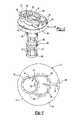
- FIG. 4is a bottom side perspective view of the diverter assembly shown in FIG. 2 ;
- FIG. 5is a bottom side perspective view of the diverter assembly shown in FIG. 4 with the filter media and cover installed.
- a filter assembly 10is shown in FIG. 1 in cross-section.
- the example assembly 10includes a housing 12 that may include a case 14 having a cover 16 secured thereto using any suitable attachment method.
- the assembly 10 shown in FIG. 1is a three port fuel filter configuration, although one of ordinary skilled in the art will appreciate that this invention is applicable to other arrangements.
- An inlet tube 18is secured to an end 15 of the housing 12 , and a return tube 22 is secured to the end 15 spaced from the inlet tube 18 .
- An outlet tube 20is secured to the cover 16 opposite the inlet 18 and return 22 tubes. Fluid may flow through the assembly 10 in a manner other than that schematically shown in FIG. 1 .
- the tubes 18 , 20 , 22may be secured to the housing 18 in any suitable manner such as by using support washers 26 and braze rings 28 to mechanically attach the tubes to the housing, as is known in the art.
- the tubes 18 , 20 , 22include beads 24 used to facilitate retention of hoses installed onto the tubes, as is well known in the art.
- the housing 12defines a cavity 30 with a filter media 32 arranged in the cavity 30 .
- a filter media 32is a pleated paper element, which is well known in the art.
- the filter media 32includes an inlet side 34 and an outlet side 36 , which in the configuration shown are respectively the outer and inner circumference of the filter media 32 .
- the flowmay be reversed from the flow indicated in FIG. 1 .
- the filter media 32must be sealed within the housing 12 in such a manner so as to ensure that the fluid passes from the inlet side 34 to the outlet side 36 without circumventing the filter media 32 so that particulates are removed from the fluid.
- one end 38 of the filter media 32is secured to the cover using an adhesive 40 such as plastisol.
- a diverter 42includes opposing first 44 and second 46 sides with an opposing end 48 of the filter media 32 secured to the second side 46 using adhesive 40 . In this manner, the filter media 32 is sealed between the diverter 42 and the cover 16 preventing fluid from circumventing the filter media 32 .
- the example diverter 42includes a base 54 constructed from a first material such as plastic.
- a second materialsuch as an elastomer is supported on the base to provide a gasket 56 .
- the second materialmay be overmolded onto the diverter base.
- suitable plasticmay be a nylon 66
- suitable elastomermay be VITON.
- any suitable materialmay be used that is chemically resistant to the fluid in which the diverter is immersed.
- the materialsare selected to provide material compatibility during the molding process. That is, the melt temperature of the over-molded material should not exceed the melt temperature of the material that is molded first. Moreover, it should be understood that processes other than over-molding may be utilized to manufacture a diverter designed according to this invention. Additionally, the base may be molded onto the gasket.
- the gasket 56creates a seal between the diverter 42 and the end 15 of the housing 12 .
- the gasket 56at least partially defines the first side 44 .
- a cylindrical wall 60may be arranged about an end portion of the return tube 22 to define an aperture 58 and create a seal between the return tube 22 and one side of the filter, which in this case is the outlet side. More specifically, the cylindrical wall 60 includes an edge 62 that is in abutment with the inner surface of the end 15 when the diverter 42 is installed into the case 14 .
- a hole 64extends between the first 44 and second 46 sides to provide fluid communication between the return tube 22 and the outlet side 36 of the filter media 32 .
- the example diverterincludes a central wall 68 having arcuate segments and is arranged between the cylindrical wall 60 and the side wall 66 to provide additional support for the diverter 42 against the housing 12 .
- the illustrated central wall 68 and side wall 66may provide support edges 70 that ensure that the end of the inlet tube 18 within the housing 12 is not blocked by the diverter 42 .
- the central wall 68may be of a different configuration than shown or eliminated entirely.
Landscapes
- Chemical & Material Sciences (AREA)
- Chemical Kinetics & Catalysis (AREA)
- Filtration Of Liquid (AREA)
Abstract
Description
Claims (13)
Priority Applications (8)
| Application Number | Priority Date | Filing Date | Title |
|---|---|---|---|
| US10/634,383US7458468B2 (en) | 2003-08-05 | 2003-08-05 | Fuel filter diverter |
| CA002475687ACA2475687A1 (en) | 2003-08-05 | 2004-07-23 | Fuel filter diverter |
| EP04254677AEP1504801A1 (en) | 2003-08-05 | 2004-08-04 | Fuel filter diverter |
| JP2004227602AJP2005095865A (en) | 2003-08-05 | 2004-08-04 | Fuel filter diverter |
| BR0403198-9ABRPI0403198A (en) | 2003-08-05 | 2004-08-04 | Fuel filter diverter |
| CN200410070041.4ACN1619135A (en) | 2003-08-05 | 2004-08-05 | Fuel filter diverter |
| US12/252,631US20090038748A1 (en) | 2003-08-05 | 2008-10-16 | Fuel Filter Diverter |
| JP2008276870AJP2009078269A (en) | 2003-08-05 | 2008-10-28 | Fuel filter diverter |
Applications Claiming Priority (1)
| Application Number | Priority Date | Filing Date | Title |
|---|---|---|---|
| US10/634,383US7458468B2 (en) | 2003-08-05 | 2003-08-05 | Fuel filter diverter |
Related Child Applications (1)
| Application Number | Title | Priority Date | Filing Date |
|---|---|---|---|
| US12/252,631DivisionUS20090038748A1 (en) | 2003-08-05 | 2008-10-16 | Fuel Filter Diverter |
Publications (2)
| Publication Number | Publication Date |
|---|---|
| US20050029184A1 US20050029184A1 (en) | 2005-02-10 |
| US7458468B2true US7458468B2 (en) | 2008-12-02 |
Family
ID=33552903
Family Applications (2)
| Application Number | Title | Priority Date | Filing Date |
|---|---|---|---|
| US10/634,383Expired - LifetimeUS7458468B2 (en) | 2003-08-05 | 2003-08-05 | Fuel filter diverter |
| US12/252,631AbandonedUS20090038748A1 (en) | 2003-08-05 | 2008-10-16 | Fuel Filter Diverter |
Family Applications After (1)
| Application Number | Title | Priority Date | Filing Date |
|---|---|---|---|
| US12/252,631AbandonedUS20090038748A1 (en) | 2003-08-05 | 2008-10-16 | Fuel Filter Diverter |
Country Status (6)
| Country | Link |
|---|---|
| US (2) | US7458468B2 (en) |
| EP (1) | EP1504801A1 (en) |
| JP (2) | JP2005095865A (en) |
| CN (1) | CN1619135A (en) |
| BR (1) | BRPI0403198A (en) |
| CA (1) | CA2475687A1 (en) |
Cited By (5)
| Publication number | Priority date | Publication date | Assignee | Title |
|---|---|---|---|---|
| US20100294712A1 (en)* | 2009-05-21 | 2010-11-25 | Cummins Filtration Ip Inc. | Multi-stage filter cartridge with polyurethane endcaps |
| US7909954B2 (en) | 2004-11-03 | 2011-03-22 | Baldwin Filters, Inc. | Method and apparatus for winding a filter media pack |
| USD681772S1 (en)* | 2012-05-17 | 2013-05-07 | General Electric Company | Fuel filter |
| USD773635S1 (en)* | 2014-02-21 | 2016-12-06 | Donaldson Company, Inc. | Filter cartridge yoke |
| US9757676B2 (en) | 2006-12-06 | 2017-09-12 | Baldwin Filters, Inc. | Method and apparatus for winding a filter element |
Families Citing this family (23)
| Publication number | Priority date | Publication date | Assignee | Title |
|---|---|---|---|---|
| US20110197556A1 (en) | 2004-11-02 | 2011-08-18 | Baldwin Filters, Inc. | Filter element |
| US7931725B2 (en) | 2004-11-02 | 2011-04-26 | Baldwin Filters, Inc. | Fluted filter apparatus |
| US20070186528A1 (en)* | 2006-02-15 | 2007-08-16 | Baldwin Filters, Inc. | Fluted filter apparatus |
| US7318851B2 (en) | 2004-11-02 | 2008-01-15 | Baldwin Filters, Inc. | Filter element |
| DE202005008680U1 (en) | 2005-06-01 | 2006-10-12 | Mann + Hummel Gmbh | Filter element for a liquid filter |
| US7753982B2 (en) | 2006-02-17 | 2010-07-13 | Baldwin Filters, Inc. | Filter with drained jacket, seal indicator/lock means, and seal baffle |
| DE102006011842A1 (en)* | 2006-03-15 | 2007-09-20 | Hydac Filtertechnik Gmbh | filter element |
| DE102007048550B4 (en)* | 2006-10-09 | 2016-12-22 | Mann + Hummel Gmbh | Fuel filter |
| KR100903317B1 (en)* | 2006-11-28 | 2009-06-16 | 기아자동차주식회사 | Housing device of fuel door |
| US10040020B2 (en) | 2006-12-06 | 2018-08-07 | Baldwin Filters, Inc. | Fluid filter apparatus having filter media wound about a winding frame |
| DE202006019301U1 (en)* | 2006-12-23 | 2008-04-30 | Mann+Hummel Gmbh | Fuel filter |
| EP2155356A4 (en)* | 2007-06-14 | 2011-04-06 | Stanadyne Corp | Filter assembly center tube with upstream diverter |
| US9545593B2 (en)* | 2007-11-01 | 2017-01-17 | Baldwin Filters, Inc. | Winding core pressure relief for fluted filter |
| US7959703B2 (en) | 2008-06-30 | 2011-06-14 | Baldwin Filters, Inc. | Fluted filter with integrated frame |
| US8048187B2 (en) | 2008-06-30 | 2011-11-01 | Baldwin Filters, Inc. | Filter frame attachment and fluted filter having same |
| DE102010015494A1 (en)* | 2010-04-16 | 2011-12-01 | Mahle International Gmbh | filtering device |
| BRPI1005768A2 (en)* | 2010-12-23 | 2013-04-24 | Mahle Metal Leve Sa | fuel filter |
| US8932464B2 (en) | 2012-03-21 | 2015-01-13 | Mann+Hummel Purolator Filters Llc | Static dissipater for a fuel filter assembly |
| BR112015001748B1 (en) | 2012-07-25 | 2022-03-15 | Baldwin Filters, Inc | filter set |
| CN104623947A (en)* | 2013-11-15 | 2015-05-20 | 上海欧菲滤清器有限公司 | Filter element and filter unit |
| CN106999806B (en)* | 2014-05-12 | 2020-05-12 | 金普奥膜科技(杭州)有限公司 | Liquid Recovery Filter |
| US10682597B2 (en) | 2016-04-14 | 2020-06-16 | Baldwin Filters, Inc. | Filter system |
| CN109838675A (en)* | 2019-03-22 | 2019-06-04 | 漯河润宝智能润滑设备有限公司 | Intelligent double site type oil feeder |
Citations (13)
| Publication number | Priority date | Publication date | Assignee | Title |
|---|---|---|---|---|
| US2031935A (en)* | 1933-04-21 | 1936-02-25 | Cuno Eng Corp | Filter |
| US2801751A (en)* | 1955-03-02 | 1957-08-06 | Marvel Eng Co | High pressure valved filters |
| US5399264A (en)* | 1993-03-22 | 1995-03-21 | Cuno, Incorporated | Compressible differential pressure energized seals for filter elements and the like |
| JPH08226358A (en) | 1995-02-20 | 1996-09-03 | Wako Sangyo Kk | Internal-combustion engine fuel supply system |
| US5685985A (en)* | 1995-12-20 | 1997-11-11 | Baldwin Filters, Inc. | Environmentally friendly filter cartridge |
| US5766289A (en) | 1995-08-16 | 1998-06-16 | Purolator Products Company | Pleated filter element and filtration unit |
| US6045693A (en)* | 1997-07-24 | 2000-04-04 | Fleetguard, Inc. | Spin-on filter assembly |
| US6068763A (en) | 1997-09-12 | 2000-05-30 | Purolator Products Company | Spin-on oil filter with replaceable element |
| US6085915A (en)* | 1996-11-22 | 2000-07-11 | Nelson Industries, Inc. | Back-washable spin-on oil filter |
| US6171492B1 (en) | 1999-02-04 | 2001-01-09 | Purolator Products Company | Filter for liquid fuel |
| JP2001104827A (en) | 1999-10-04 | 2001-04-17 | Hitachi Koki Co Ltd | centrifuge |
| WO2001030477A1 (en) | 1999-10-25 | 2001-05-03 | Purolator Products Na, Inc. | Fuel filter flow diverter |
| US6248236B1 (en)* | 1993-09-15 | 2001-06-19 | Parker-Hannifin Corporation | Double pass fuel filter assembly |
Family Cites Families (5)
| Publication number | Priority date | Publication date | Assignee | Title |
|---|---|---|---|---|
| US3111488A (en)* | 1960-11-23 | 1963-11-19 | Purolator Products Inc | Liquid filter |
| JP2000199566A (en)* | 1998-10-30 | 2000-07-18 | Bridgestone Corp | Gasket with cover |
| JP2000167314A (en)* | 1998-12-10 | 2000-06-20 | Yamashin Kogyo Kk | Filter element |
| US6117311A (en)* | 1999-01-08 | 2000-09-12 | Champion Laboratores, Inc. | Positive shut off fuel pump dispensing filter |
| US7014761B2 (en)* | 2002-06-07 | 2006-03-21 | Baldwin Filters, Inc. | Environmentally friendly dual lube venturi filter cartridge |
- 2003
- 2003-08-05USUS10/634,383patent/US7458468B2/ennot_activeExpired - Lifetime
- 2004
- 2004-07-23CACA002475687Apatent/CA2475687A1/ennot_activeAbandoned
- 2004-08-04EPEP04254677Apatent/EP1504801A1/ennot_activeWithdrawn
- 2004-08-04BRBR0403198-9Apatent/BRPI0403198A/ennot_activeIP Right Cessation
- 2004-08-04JPJP2004227602Apatent/JP2005095865A/enactivePending
- 2004-08-05CNCN200410070041.4Apatent/CN1619135A/enactivePending
- 2008
- 2008-10-16USUS12/252,631patent/US20090038748A1/ennot_activeAbandoned
- 2008-10-28JPJP2008276870Apatent/JP2009078269A/enactivePending
Patent Citations (13)
| Publication number | Priority date | Publication date | Assignee | Title |
|---|---|---|---|---|
| US2031935A (en)* | 1933-04-21 | 1936-02-25 | Cuno Eng Corp | Filter |
| US2801751A (en)* | 1955-03-02 | 1957-08-06 | Marvel Eng Co | High pressure valved filters |
| US5399264A (en)* | 1993-03-22 | 1995-03-21 | Cuno, Incorporated | Compressible differential pressure energized seals for filter elements and the like |
| US6248236B1 (en)* | 1993-09-15 | 2001-06-19 | Parker-Hannifin Corporation | Double pass fuel filter assembly |
| JPH08226358A (en) | 1995-02-20 | 1996-09-03 | Wako Sangyo Kk | Internal-combustion engine fuel supply system |
| US5766289A (en) | 1995-08-16 | 1998-06-16 | Purolator Products Company | Pleated filter element and filtration unit |
| US5685985A (en)* | 1995-12-20 | 1997-11-11 | Baldwin Filters, Inc. | Environmentally friendly filter cartridge |
| US6085915A (en)* | 1996-11-22 | 2000-07-11 | Nelson Industries, Inc. | Back-washable spin-on oil filter |
| US6045693A (en)* | 1997-07-24 | 2000-04-04 | Fleetguard, Inc. | Spin-on filter assembly |
| US6068763A (en) | 1997-09-12 | 2000-05-30 | Purolator Products Company | Spin-on oil filter with replaceable element |
| US6171492B1 (en) | 1999-02-04 | 2001-01-09 | Purolator Products Company | Filter for liquid fuel |
| JP2001104827A (en) | 1999-10-04 | 2001-04-17 | Hitachi Koki Co Ltd | centrifuge |
| WO2001030477A1 (en) | 1999-10-25 | 2001-05-03 | Purolator Products Na, Inc. | Fuel filter flow diverter |
Non-Patent Citations (4)
| Title |
|---|
| Abstract for JP2000501991, which corresponds to US5685985, which is already of record. |
| EP04254677 Search Report. |
| European office action dated Sep. 8, 2008. |
| Japanese office action dated Jul. 29, 2008, with English translation. |
Cited By (7)
| Publication number | Priority date | Publication date | Assignee | Title |
|---|---|---|---|---|
| US7909954B2 (en) | 2004-11-03 | 2011-03-22 | Baldwin Filters, Inc. | Method and apparatus for winding a filter media pack |
| US9757676B2 (en) | 2006-12-06 | 2017-09-12 | Baldwin Filters, Inc. | Method and apparatus for winding a filter element |
| US10065146B2 (en) | 2006-12-06 | 2018-09-04 | Baldwin Filters, Inc. | Method and apparatus for winding a filter element |
| US20100294712A1 (en)* | 2009-05-21 | 2010-11-25 | Cummins Filtration Ip Inc. | Multi-stage filter cartridge with polyurethane endcaps |
| US8216470B2 (en)* | 2009-05-21 | 2012-07-10 | Cummins Filtration Ip, Inc. | Multi-stage filter cartridge with polyurethane endcaps |
| USD681772S1 (en)* | 2012-05-17 | 2013-05-07 | General Electric Company | Fuel filter |
| USD773635S1 (en)* | 2014-02-21 | 2016-12-06 | Donaldson Company, Inc. | Filter cartridge yoke |
Also Published As
| Publication number | Publication date |
|---|---|
| BRPI0403198A (en) | 2005-05-24 |
| CN1619135A (en) | 2005-05-25 |
| US20050029184A1 (en) | 2005-02-10 |
| EP1504801A1 (en) | 2005-02-09 |
| JP2009078269A (en) | 2009-04-16 |
| CA2475687A1 (en) | 2005-02-05 |
| JP2005095865A (en) | 2005-04-14 |
| US20090038748A1 (en) | 2009-02-12 |
Similar Documents
| Publication | Publication Date | Title |
|---|---|---|
| US7458468B2 (en) | Fuel filter diverter | |
| US7147110B2 (en) | Filter assembly with vented filter element | |
| US6571962B2 (en) | Cartridge filter element with housing seal retainer | |
| US10137390B2 (en) | Filter device, especially liquid filter | |
| EP3461548B1 (en) | Spin-on filter with external threads and methods | |
| KR102198141B1 (en) | Filter element with undulating seal | |
| CN105032000B (en) | Without the spin-on filter of plate nut | |
| US10399020B2 (en) | Filter element and filter system with siphon venting arrangement | |
| PL237677B1 (en) | Fuel filter element, filter assembly and method for producing the filter element | |
| CN204458137U (en) | Fuel filter | |
| US8020709B2 (en) | Filter element | |
| JP4374566B2 (en) | Filter cartridge assembly and manufacturing method thereof | |
| US12161957B2 (en) | Integral filter endcap, mold, and seal | |
| US10328369B2 (en) | Filter element and filter system for a liquid medium with ventilation on the post-filtration side and on the pre-filtration side | |
| JP7295601B2 (en) | Filter element cartridge and filtration device | |
| JP4780028B2 (en) | Element exchange type fluid filter |
Legal Events
| Date | Code | Title | Description |
|---|---|---|---|
| AS | Assignment | Owner name:ARVINMERITOR TECHNOLOGY, LLC, MICHIGAN Free format text:ASSIGNMENT OF ASSIGNORS INTEREST;ASSIGNOR:DESMARAIS, CHRISTOPHER P.;REEL/FRAME:014382/0658 Effective date:20030804 | |
| AS | Assignment | Owner name:PUROLATOR PRODUCTS NA, LLC, MICHIGAN Free format text:ASSIGNMENT OF ASSIGNORS INTEREST;ASSIGNOR:ARVINMERITOR TECHNOLOGY, LLC;REEL/FRAME:016655/0412 Effective date:20050614 | |
| AS | Assignment | Owner name:PUROLATOR FILTERS NA LLC,NORTH CAROLINA Free format text:ASSIGNMENT OF ASSIGNORS INTEREST;ASSIGNOR:PUROLATOR PRODUCTS NA, LLC;REEL/FRAME:017892/0153 Effective date:20060330 Owner name:PUROLATOR FILTERS NA LLC, NORTH CAROLINA Free format text:ASSIGNMENT OF ASSIGNORS INTEREST;ASSIGNOR:PUROLATOR PRODUCTS NA, LLC;REEL/FRAME:017892/0153 Effective date:20060330 | |
| STCF | Information on status: patent grant | Free format text:PATENTED CASE | |
| FPAY | Fee payment | Year of fee payment:4 | |
| AS | Assignment | Owner name:MANN+HUMMEL PUROLATOR FILTERS LLC, NORTH CAROLINA Free format text:ASSIGNMENT OF ASSIGNORS INTEREST;ASSIGNOR:PUROLATOR FILTERS NA LLC;REEL/FRAME:031448/0171 Effective date:20130822 | |
| FPAY | Fee payment | Year of fee payment:8 | |
| MAFP | Maintenance fee payment | Free format text:PAYMENT OF MAINTENANCE FEE, 12TH YEAR, LARGE ENTITY (ORIGINAL EVENT CODE: M1553); ENTITY STATUS OF PATENT OWNER: LARGE ENTITY Year of fee payment:12 |