US7458158B2 - Method of making a sliding bearing - Google Patents
Method of making a sliding bearingDownload PDFInfo
- Publication number
- US7458158B2 US7458158B2US11/169,032US16903205AUS7458158B2US 7458158 B2US7458158 B2US 7458158B2US 16903205 AUS16903205 AUS 16903205AUS 7458158 B2US7458158 B2US 7458158B2
- Authority
- US
- United States
- Prior art keywords
- bearing surface
- bearing
- cavities
- depositing
- polymer
- Prior art date
- Legal status (The legal status is an assumption and is not a legal conclusion. Google has not performed a legal analysis and makes no representation as to the accuracy of the status listed.)
- Expired - Fee Related, expires
Links
Images


Classifications
- B—PERFORMING OPERATIONS; TRANSPORTING
- B23—MACHINE TOOLS; METAL-WORKING NOT OTHERWISE PROVIDED FOR
- B23P—METAL-WORKING NOT OTHERWISE PROVIDED FOR; COMBINED OPERATIONS; UNIVERSAL MACHINE TOOLS
- B23P15/00—Making specific metal objects by operations not covered by a single other subclass or a group in this subclass
- B23P15/003—Making specific metal objects by operations not covered by a single other subclass or a group in this subclass bearings
- F—MECHANICAL ENGINEERING; LIGHTING; HEATING; WEAPONS; BLASTING
- F16—ENGINEERING ELEMENTS AND UNITS; GENERAL MEASURES FOR PRODUCING AND MAINTAINING EFFECTIVE FUNCTIONING OF MACHINES OR INSTALLATIONS; THERMAL INSULATION IN GENERAL
- F16C—SHAFTS; FLEXIBLE SHAFTS; ELEMENTS OR CRANKSHAFT MECHANISMS; ROTARY BODIES OTHER THAN GEARING ELEMENTS; BEARINGS
- F16C33/00—Parts of bearings; Special methods for making bearings or parts thereof
- F16C33/02—Parts of sliding-contact bearings
- B—PERFORMING OPERATIONS; TRANSPORTING
- B21—MECHANICAL METAL-WORKING WITHOUT ESSENTIALLY REMOVING MATERIAL; PUNCHING METAL
- B21D—WORKING OR PROCESSING OF SHEET METAL OR METAL TUBES, RODS OR PROFILES WITHOUT ESSENTIALLY REMOVING MATERIAL; PUNCHING METAL
- B21D53/00—Making other particular articles
- B21D53/10—Making other particular articles parts of bearings; sleeves; valve seats or the like
- F—MECHANICAL ENGINEERING; LIGHTING; HEATING; WEAPONS; BLASTING
- F16—ENGINEERING ELEMENTS AND UNITS; GENERAL MEASURES FOR PRODUCING AND MAINTAINING EFFECTIVE FUNCTIONING OF MACHINES OR INSTALLATIONS; THERMAL INSULATION IN GENERAL
- F16C—SHAFTS; FLEXIBLE SHAFTS; ELEMENTS OR CRANKSHAFT MECHANISMS; ROTARY BODIES OTHER THAN GEARING ELEMENTS; BEARINGS
- F16C17/00—Sliding-contact bearings for exclusively rotary movement
- F16C17/02—Sliding-contact bearings for exclusively rotary movement for radial load only
- F16C17/03—Sliding-contact bearings for exclusively rotary movement for radial load only with tiltably-supported segments, e.g. Michell bearings
- F16C17/035—Sliding-contact bearings for exclusively rotary movement for radial load only with tiltably-supported segments, e.g. Michell bearings the segments being integrally formed with, or rigidly fixed to, a support-element
- F—MECHANICAL ENGINEERING; LIGHTING; HEATING; WEAPONS; BLASTING
- F16—ENGINEERING ELEMENTS AND UNITS; GENERAL MEASURES FOR PRODUCING AND MAINTAINING EFFECTIVE FUNCTIONING OF MACHINES OR INSTALLATIONS; THERMAL INSULATION IN GENERAL
- F16C—SHAFTS; FLEXIBLE SHAFTS; ELEMENTS OR CRANKSHAFT MECHANISMS; ROTARY BODIES OTHER THAN GEARING ELEMENTS; BEARINGS
- F16C17/00—Sliding-contact bearings for exclusively rotary movement
- F16C17/04—Sliding-contact bearings for exclusively rotary movement for axial load only
- F16C17/06—Sliding-contact bearings for exclusively rotary movement for axial load only with tiltably-supported segments, e.g. Michell bearings
- F16C17/065—Sliding-contact bearings for exclusively rotary movement for axial load only with tiltably-supported segments, e.g. Michell bearings the segments being integrally formed with, or rigidly fixed to, a support-element
- F—MECHANICAL ENGINEERING; LIGHTING; HEATING; WEAPONS; BLASTING
- F16—ENGINEERING ELEMENTS AND UNITS; GENERAL MEASURES FOR PRODUCING AND MAINTAINING EFFECTIVE FUNCTIONING OF MACHINES OR INSTALLATIONS; THERMAL INSULATION IN GENERAL
- F16C—SHAFTS; FLEXIBLE SHAFTS; ELEMENTS OR CRANKSHAFT MECHANISMS; ROTARY BODIES OTHER THAN GEARING ELEMENTS; BEARINGS
- F16C33/00—Parts of bearings; Special methods for making bearings or parts thereof
- F16C33/02—Parts of sliding-contact bearings
- F16C33/04—Brasses; Bushes; Linings
- F16C33/06—Sliding surface mainly made of metal
- F16C33/10—Construction relative to lubrication
- F16C33/1025—Construction relative to lubrication with liquid, e.g. oil, as lubricant
- F16C33/103—Construction relative to lubrication with liquid, e.g. oil, as lubricant retained in or near the bearing
- F—MECHANICAL ENGINEERING; LIGHTING; HEATING; WEAPONS; BLASTING
- F16—ENGINEERING ELEMENTS AND UNITS; GENERAL MEASURES FOR PRODUCING AND MAINTAINING EFFECTIVE FUNCTIONING OF MACHINES OR INSTALLATIONS; THERMAL INSULATION IN GENERAL
- F16C—SHAFTS; FLEXIBLE SHAFTS; ELEMENTS OR CRANKSHAFT MECHANISMS; ROTARY BODIES OTHER THAN GEARING ELEMENTS; BEARINGS
- F16C33/00—Parts of bearings; Special methods for making bearings or parts thereof
- F16C33/02—Parts of sliding-contact bearings
- F16C33/04—Brasses; Bushes; Linings
- F16C33/06—Sliding surface mainly made of metal
- F16C33/10—Construction relative to lubrication
- F16C33/1025—Construction relative to lubrication with liquid, e.g. oil, as lubricant
- F16C33/106—Details of distribution or circulation inside the bearings, e.g. details of the bearing surfaces to affect flow or pressure of the liquid
- F16C33/1075—Wedges, e.g. ramps or lobes, for generating pressure
- F—MECHANICAL ENGINEERING; LIGHTING; HEATING; WEAPONS; BLASTING
- F16—ENGINEERING ELEMENTS AND UNITS; GENERAL MEASURES FOR PRODUCING AND MAINTAINING EFFECTIVE FUNCTIONING OF MACHINES OR INSTALLATIONS; THERMAL INSULATION IN GENERAL
- F16C—SHAFTS; FLEXIBLE SHAFTS; ELEMENTS OR CRANKSHAFT MECHANISMS; ROTARY BODIES OTHER THAN GEARING ELEMENTS; BEARINGS
- F16C33/00—Parts of bearings; Special methods for making bearings or parts thereof
- F16C33/02—Parts of sliding-contact bearings
- F16C33/04—Brasses; Bushes; Linings
- F16C33/26—Brasses; Bushes; Linings made from wire coils; made from a number of discs, rings, rods, or other members
- F—MECHANICAL ENGINEERING; LIGHTING; HEATING; WEAPONS; BLASTING
- F16—ENGINEERING ELEMENTS AND UNITS; GENERAL MEASURES FOR PRODUCING AND MAINTAINING EFFECTIVE FUNCTIONING OF MACHINES OR INSTALLATIONS; THERMAL INSULATION IN GENERAL
- F16C—SHAFTS; FLEXIBLE SHAFTS; ELEMENTS OR CRANKSHAFT MECHANISMS; ROTARY BODIES OTHER THAN GEARING ELEMENTS; BEARINGS
- F16C33/00—Parts of bearings; Special methods for making bearings or parts thereof
- F16C33/30—Parts of ball or roller bearings
- F16C33/58—Raceways; Race rings
- F16C33/62—Selection of substances
- F—MECHANICAL ENGINEERING; LIGHTING; HEATING; WEAPONS; BLASTING
- F02—COMBUSTION ENGINES; HOT-GAS OR COMBUSTION-PRODUCT ENGINE PLANTS
- F02F—CYLINDERS, PISTONS OR CASINGS, FOR COMBUSTION ENGINES; ARRANGEMENTS OF SEALINGS IN COMBUSTION ENGINES
- F02F1/00—Cylinders; Cylinder heads
- F02F1/18—Other cylinders
- F02F1/20—Other cylinders characterised by constructional features providing for lubrication
- F—MECHANICAL ENGINEERING; LIGHTING; HEATING; WEAPONS; BLASTING
- F02—COMBUSTION ENGINES; HOT-GAS OR COMBUSTION-PRODUCT ENGINE PLANTS
- F02F—CYLINDERS, PISTONS OR CASINGS, FOR COMBUSTION ENGINES; ARRANGEMENTS OF SEALINGS IN COMBUSTION ENGINES
- F02F3/00—Pistons
- F02F3/10—Pistons having surface coverings
- Y—GENERAL TAGGING OF NEW TECHNOLOGICAL DEVELOPMENTS; GENERAL TAGGING OF CROSS-SECTIONAL TECHNOLOGIES SPANNING OVER SEVERAL SECTIONS OF THE IPC; TECHNICAL SUBJECTS COVERED BY FORMER USPC CROSS-REFERENCE ART COLLECTIONS [XRACs] AND DIGESTS
- Y10—TECHNICAL SUBJECTS COVERED BY FORMER USPC
- Y10T—TECHNICAL SUBJECTS COVERED BY FORMER US CLASSIFICATION
- Y10T29/00—Metal working
- Y10T29/49—Method of mechanical manufacture
- Y10T29/49636—Process for making bearing or component thereof
- Y10T29/49705—Coating or casting
- Y—GENERAL TAGGING OF NEW TECHNOLOGICAL DEVELOPMENTS; GENERAL TAGGING OF CROSS-SECTIONAL TECHNOLOGIES SPANNING OVER SEVERAL SECTIONS OF THE IPC; TECHNICAL SUBJECTS COVERED BY FORMER USPC CROSS-REFERENCE ART COLLECTIONS [XRACs] AND DIGESTS
- Y10—TECHNICAL SUBJECTS COVERED BY FORMER USPC
- Y10T—TECHNICAL SUBJECTS COVERED BY FORMER US CLASSIFICATION
- Y10T29/00—Metal working
- Y10T29/49—Method of mechanical manufacture
- Y10T29/49636—Process for making bearing or component thereof
- Y10T29/49709—Specific metallic composition
- Y—GENERAL TAGGING OF NEW TECHNOLOGICAL DEVELOPMENTS; GENERAL TAGGING OF CROSS-SECTIONAL TECHNOLOGIES SPANNING OVER SEVERAL SECTIONS OF THE IPC; TECHNICAL SUBJECTS COVERED BY FORMER USPC CROSS-REFERENCE ART COLLECTIONS [XRACs] AND DIGESTS
- Y10—TECHNICAL SUBJECTS COVERED BY FORMER USPC
- Y10T—TECHNICAL SUBJECTS COVERED BY FORMER US CLASSIFICATION
- Y10T29/00—Metal working
- Y10T29/49—Method of mechanical manufacture
- Y10T29/4998—Combined manufacture including applying or shaping of fluent material
Definitions
- This inventionrelates generally to a method modifying a bearing surface of a sliding bearing member. More particularly, it relates to a method of adding at least one surface feature as a coating to a wear surface by selective deposition of the coating in the shape of the feature on the bearing surface.
- a bearingis defined in a general sense as a means of positioning one member with respect to another member in such a way that relative motion of the members is possible.
- the membershave respective bearing surfaces which are in bearing contact with one another, typically through a lubricant which is used to promote the relative movement of the members, reduce wear of the bearing surfaces, reducing corrosion and for other purposes.
- the relative motion of the bearing surfaces and the bearing typeare dictated by the requirements of the application of which the bearing surfaces will be a part. Bearings and bearing surfaces are designed by determining the mechanical motion and functions which they must perform, and the application requirements for life and reliability and the ambient conditions, including temperature, potential contaminants, the potential for corrosion, vibration, cyclic stresses and others.
- sliding bearingsin which the bearing surfaces of the bearing elements are usually separated by a thin film of coating of a lubricant such as various types of oils and greases.
- Sliding bearingsencompass a broad range of devices in which the relative movement of the bearing elements involves sliding movement of one bearing surface over the other bearing surface.
- Such devicesinclude all types of journal or sleeve bearings which are used to position a shaft or movable part in a radial direction, as well as all types of thrust bearings which are used in general to prevent movement of a rotating shaft in an axial direction and as guides for linear motion of various types.
- Thrust bearingsvary widely in design as well, ranging from simple, flat thrust collars to complex tapered-end and pivoted-shoe (i.e., Kingsbury) bearings.
- Some journal and thrust bearingsare designed to operate with a lubricant supply under sufficient external pressure so that the load is carried by through the pressurized fluid rather than by the hydrodynamic forces generated by the sliding motion.
- Other bearingsmove slowly enough, or intermittently, or under sufficiently light loads so that separation by a film of lubricant is not necessary for satisfactory performance and life.
- the surfacesare allowed to rub on each other with only the boundary-lubrication properties of the lubricant, which may comprise one or both of the bearing surfaces, or the surface properties of the bearing surfaces themselves, preventing seizure and wear.
- Another broad category of sliding bearing and bearing surfacesinclude many reciprocating piston/cylinder applications, such as the bearing comprising the drive piston/cylinder of an internal combustion engine.
- Lubricantscome in many forms and compositions, from various fluids, including water, oil, soaps, greases and air, to solid lubricants such as graphite, molybdenum disulfide, polytetrafluoroethylene (PTFE) and others.
- bearingsThere are also typically economic and environmental requirements to be considered in the selection of bearings. In this respect, the principal economic factors are life and reliability, maintenance, ease of replacement and cost. Sliding bearings, when properly designed and when operating under reasonably uniform loading with compatible material, may have excellent longevity. As to cost, sliding bearings can frequently be produced at very small cost in mass-production quantities, but their cost can be very large, when they have to be produced in small quantities for special designs. Thus, methods of making such bearings will preferably have a minimum number of required steps and be well adapted for automation and/or high volume manufacturing methods.
- journal bearingsare one type of sliding bearing. Journal bearings are classified roughly according to the method of lubricant feed to them, as (a) non-pressurized bearings, (b) pressure-fed bearings, or (c) externally pressurized bearings. Examples of non-pressurized bearing are bushings, wick-oil bearings and oil ring bearings. Pressure-fed bearings have lubricant (i.e., oil) which is fed under pressure.
- lubricanti.e., oil
- a pressure-fed bearing systemmay include a storage tank, a pump, either a full flow or bypass-type filter or centrifuge, a cooler, a pressure regulator, a temperature regulator, supply lines to the bearings, and return lines from the bearings (which drain the lubricant from the bearings back to the tank).
- Examples of pressure-fed bearingsinclude circumferential-groove, cylindrical, cylindrical overshoot, pressure, multiple groove, elliptical, elliptical overshoot, three-low, pivoted-shoe, nutcracker and partial sliding bearings.
- Externally pressurized bearingssuch as pocket bearings and hydrostatic bearings, depend upon lubricant (i.e., oil) pressure from an external pressure source to support the bearing load. This differs from hydrodynamic bearings, which depend upon lubricant pressures generated in the lubricant film to support the load.
- thrust bearingsare a second general type of sliding bearing.
- the types of thrust bearingsinclude low-speed bearings, which largely depend upon boundary lubrication, types which operate on hydrodynamic principals and externally pressurized thrust bearings. These include flat-land thrust bearings, tapered-land thrust bearings, pivoted-shoe thrust bearings or Kingsbury bearings, spring-supported flexible-plate thrust bearings, step thrust bearings and pocket thrust bearings.
- sliding bearing and associated bearing surfacesinclude any of a number of piston and associated cylinder liner. These include reciprocating pistons used in numerous internal combustion engines and many other applications. Reciprocating pistons and their associated cylinder housings typically require continuous lubrication of the bearing surfaces, including both the piston and cylinder sidewalls.
- a drive mechanismsuch as a crankshaft
- the wristpinis also connected to a bore in a connecting rod using a similar bearing arrangement.
- the connecting rodis in turn connected to the crankshaft through a sleeve bearing.
- piston ringsare coupled with the cylinder liner.
- the surface patterns on the piston surfacestrengthen the function of piston rings; they may reduce or even eliminate the rings for low cost. All of the elements of the piston/cylinder bearing and bearings associated with the linkage require lubrication, and friction and wear properties are some of the principal design requirements.
- Yet another sliding bearing arrangementis a ball and socket connection, such as is described in U.S. 462,362 to Yuhta et al.
- a ball having a semi-spherical bearing surface or a other curved bearing surfaceis used with a mating socket having a mating bearing surface.
- Applications for such bearingsinclude artificial hip joints.
- Non-conductive materialsmay include various engineering plastics, such as nylon, polytetrafluoroethylene (PTFE), ceramics, molded-fabric, wood and many other non-conductive materials.
- the conductive materialsmay be formed by numerous metalworking methods, including casting, sintering, forging and other known methods, and will frequently employ machining, grinding, polishing and other well-known finishing operations to produce the finished bearing shape and surface finish.
- hard materialsare frequently not suitable for use as bearing materials because they generally have low fracture toughness.
- the use of various hard coatings for bearing surfaceshave been proposed, but they are also known to be prone to failure under high surface stress conditions due to low fracture toughness or problems associated with the adhesion of the bearing surface coating to the underlying bearing material.
- the proposed surface structureswill settle the dilemma imposed by the convention of continuous uniform surface. Separate surface elements with different materials are so designed as to satisfy conflicting surface requirements.
- the proposed surface structure with relative thin/pattered layers and different materials from the substrate materialswill settle the dilemma; thus, the engineered surfaces can give better performance to retain lubricants, pumping lubricant, and resist wear without compromising the performance and cost of the bearing substrate.
- the bearing substrateneeds to have sufficient structural strength instead of wear resistance and lubricant enhancement.
- the materials conflictcan be satisfied by the composite surface.
- Advanced materials processing technologiesare necessary to realize these surfaces. These processes include electrochemical, electro-plasma, and photo-dielectric lithography, etc. Optimal combination of several processes is organized to achieve the best production efficiency and lowest cost. Advanced materials processing technologies are necessary to realize these surfaces. These processes include electrochemical, electrophoretic, electro-plasma, electrostatic, and photo-dielectric lithography, etc. The combination of several processes is optimized to achieve the best production efficiency and lowest cost.
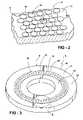
- FIG. 1is a perspective view of an embodiment of a thrust washer made in accordance with the method of the present invention
- FIG. 2is an enlarged view of a portion of FIG. 1 ;
- FIG. 3is a perspective view of a second embodiment of a thrust washer made in accordance with the method of the present invention.
- FIG. 4is an enlarged view of a portion of FIG. 3 ;
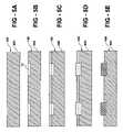
- FIGS. 5A-5Eis a schematic illustration of the steps of one embodiment of the method of the present invention.
- FIGS. 6A-6Fis a schematic illustration of the steps of a second embodiment of the method of the present invention.
- FIGS. 7A-7Fis a schematic illustration of the steps of a third embodiment of the method of the present invention.
- FIG. 8is a perspective view of a piston having a bearing surface made in accordance with a method of the present invention.
- FIG. 9is a perspective view of a sleeve bearing having a bearing surface made in accordance with the method of the present invention.
- FIG. 10is a schematic illustration of a cylinder having a bearing surface made in accordance with the method of the present invention.
- FIG. 11is a schematic illustration of a cylinder having a bearing surface made in accordance with the method of the present invention.
- FIG. 12is a perspective view of a piston ring having surface features according to another embodiment of the invention.
- the present inventionis a method of making a sliding bearing having a bearing surface which includes at least one of bearing surface feature which is located in and extends upwardly from a corresponding plurality of cavities formed in the bearing surface.
- the at least one bearing surface featureis preferably made from a bearing surface material and formed in a predetermined pattern so as to improve at least one of the friction and wear characteristics of the bearing surface, and consequently of the bearing also.
- FIGS. 1-2 and FIGS. 3-4illustrate two examples, respectively, of a bearing having at least one bearing surface feature which may be made by the method of the present invention.
- FIGS. 1-2illustrate one example of bearing element 6 of a sliding bearing 8 in the form of a thrust washer 10 having a bearing surface 12 which includes a plurality of bearing surface features 14 in the form of cylindrical pads 16 . These features 14 are located within a plurality of correspondingly shaped cavities 17 (best shown in FIG. 5 ) or recesses located on bearing surface 12 and which together comprise a portion of bearing surface 12 .
- the use of the term bearing surface feature 14is intended to connote the wide variety of shapes and patterns that may be utilized, as well as the wide variety of sizes of the same.
- FIGS. 3-4illustrate a second example of a thrust washer 10 having a bearing surface 12 which includes a bearing surface feature 14 in the form of a ring 18 having a plurality of arcuate ring segments grooves 20 spaced circumferentially about the ring 18 .
- These bearing surface features 14are preferably selected to promote the retention of, or direct the flow of, a lubricant (not shown) used in conjunction with the operation of the bearing 8 .
- FIGS. 7-10illustrate two exemplary embodiments of bearing surface features 14 which may be made in accordance with the method of the present invention
- any suitable pattern or shape of bearing surface features 14may be formed on bearing surface 12 , depending on the intended application of the bearing 8 .
- the method of the inventionmay be applied to a bearing surface 12 of any of the elements 6 of any of a number of types of sliding bearings 8 , as illustrated generally in FIGS. 7-10 .
- FIG. 8illustrates incorporation of the bearing surface features 14 on several of the bearing surfaces 12 of a piston 22 , such as the pin bore 24 and the skirt face 26 .
- FIG. 9illustrates the incorporation of the bearing surface features 14 on several of the bearing surfaces 12 of a sleeve bearing 28 as might be used for a crankshaft.
- FIG. 9illustrates another embodiment of bearing surface features 14 on a bearing surface 12 , such as the crown or skirt of a piston, in the form of a grid of spaced apart rectangular pads 30 . It is believed that the spaces 32 between the pads will assist to retain oil in them during the operation of piston.
- FIG. 11illustrates another embodiment of bearing surface features 14 on a bearing surface 12 , such as the crown or skirt of a piston, in the form of a grid of spaced apart arcuate pads 34 . It is believed that arcuate pads 34 may provide a hydrodynamic pumping action on a lubricant such as oil during the reciprocation of piston 29 .
- bearing surface 12may be added to bearing surface 12 depending on the type of bearing 8 being considered and the desired wear, friction and lubrication requirements of the bearing surface 12 and other factors.
- the bearing surface features 14basically consist of dense pads or patterns that are embedded into the bearing surface 12 (or surfaces) of the bearing 8 that are subject to frictional contact and wear.
- the bearing 8including bearing surface 12 , and bearing surface features 14 can be made from different materials.
- FIGS. 1 and 2illustrate one example of bearing surface features 14 .
- the bearing surface features 14may comprise a hard layer which is relatively harder than the material of the bearing surface 12 to provide enhanced wear resistance.
- examples of hard materials for use as bearing surface features 14include materials such as chrome and many ceramic materials, including metal oxides, nitrides and carbides.
- bearing surface features 14can provide wear resistance by acting to reduce the coefficient of friction of the bearing surface 12 taken as a whole.
- bearing surface features 14should comprise a lubricious material as a solid lubricant, for example, PTFE, graphite, polyimide, molybdenum disulfide or other well-known solid lubricants.
- spaces 50 and 32 between the bearing surface features 14isolate intrinsic stresses within the material used to form the feature, which may result from the deposition method employed to deposit the material of bearing surface feature 14 or from a mismatch between the coefficients of thermal expansion of the feature and the bearing surface 12 and also provide oil retention for lubrication of the bearing surface 12 .
- FIGS. 3 and 4show another example of bearing surface features 14 which may be made in accordance with the method of the invention.
- the space between the padscan be formed as pumping grooves for dynamic sealing and lubrication.
- the details of their shape and designwill depend on the bearing function and geometry and may include a variety of forms and derivatives.
- Multi-layer coatings and structuresmay be utilized as bearing surface features 14 . This includes multi-layer structures which may not be possible to use as a friction reducing or wear resistant coating layer over the entire bearing surface 12 due to intrinsic stresses within such a coating that can exceed the adhesion strength of the coating layer.
- the surface bearing features 14are separated into discrete pads as shown in FIGS. 1 and 2 . These pads may be made from hard coating materials, such as ceramic and chrome and are very resistant to compression and wear loads.
- the substrate or bearing surface 12may be made from less hard but tougher materials, such as low carbon steel and aluminum, and takes the tensile and thermal stresses as a structural support. In this configuration, the wear resistance of the bearing surface 12 is increased while at the same time reducing the likelihood of the separation of the hard coating.
- the surface bearing feature 14is separated into discrete pads as shown in FIGS. 1 and 2 .
- These padsmay be made from lubricious materials, such as PTFE, which acts as a solid lubricant and enables reduction of friction with little surface oil.
- the substrate or bearing surface 12may be made from materials, such as low carbon steel and aluminum, to take the tensile and thermal stresses as a structural support member. In this configuration, the friction loss is reduced without the conflict of surface weakening. In general, the smaller and denser the pads are, the stronger the surface and the less likelihood of separation of the bearing surface feature 14 caused by intrinsic stresses in the coating layer. Overall part performance including friction loss, fracture toughness, and structure strength are improved with lower material and processing cost.
- the spaces 50 and 32 between the bearing surface features 14there are two roles of the spaces 50 and 32 between the bearing surface features 14 .
- One roleis to isolate the surface stresses when hard coating material are employed as previously mentioned.
- the spaces which separate the featuressuch as shown in FIGS. 1 and 2 can play a role as a retention means for lubricant.
- a local lubricant reservoir on the bearing surfaceis very desirable for extremely low and very high motion speeds of the bearing surfaces to prevent oil starvation and wear processes which result from such starvation.
- the space between the supporting padscan be formed so as to function as a plurality of hydrodynamic pumping grooves 20 for dynamic lubrication or sealing by providing bearing surface feature 14 in the form of ring 18 having grooves 20 which are preferably raised slightly above bearing surface 12 .
- bearing surface feature 14in the form of ring 18 having grooves 20 which are preferably raised slightly above bearing surface 12 .
- a lubricantsuch as an oil is provided to the outer portion 40 of bearing surface 12 .
- the lubricantis subject to a hydrodynamic pumping action through grooves 20 in response to the relative rotation of bearing surface 12 and the mating bearing surface.
- the lubricantis driven into the inner portion 42 of bearing surface 12 through these grooves 20 .
- the method of the inventionmay also be adapted to provide an adhesion promoter 44 or an adhesion layer between the portion of the bearing surface 12 within the plurality of cavities 17 and the lower surface 46 of the bearing surface feature 14 .
- the adhesion promoter 44may be formed of any material which increases the adhesion strength of the bearing surface feature 14 to the portion of the bearing surface 12 at the interface 48 between them as compared to the strength of this interface when the adhesion promoter 44 is not present.
- the material used for adhesion promoter 44will depend upon the materials selected for bearing surface 12 and bearing surface feature 14 . In the case where these are metals or ceramics, well-known adhesion promoters such as a thin layer of chromium or titanium may be applied using known deposition methods.
- bearing surface 12is a metal and bearing surface feature 14 is an engineering plastic such as PTFE, polyimide, or a non-metal or mineral, such as graphite or asbestos
- the adhesion promoter 44may comprise any of a number of well-known organic or other adhesives for bonding these materials to the metal bearing surface 12 .
- bearing surface features 14 made according to the method of the present inventionare multi-functional. They may form various combinations of low friction coefficient, tough, and strong bearing contacts.
- the spaces 50 of bearing surface 12 not taken up by bearing surface features 14act as recesses on bearing surface 12 which provide for lubricant retention and hydrodynamic pumping as well as providing spacing between adjacent features which serves as a means of limiting or isolating the intrinsic stresses associated with the bearing surface features 14 .
- the bearing surface features 14effectively resist the wear bearing surface 12 , by at least one of providing a harder wear surface or providing a wear surface that has a reduced coefficient of friction over that of the bearing surface 12 .
- the bearing surface 12 and bearing 8take the normal, shear and thermal loads, the cavities 17 in the bearing surface 12 serve to retain the bearing surface features 14 .
- the present inventionincludes a method 100 of making a sliding bearing 8 .
- method 100includes the steps of: fabricating 200 a bearing member 8 of a first material having a bearing surface 12 ; forming 300 a plurality of cavities 17 in the bearing surface such that a portion of the bearing surface 12 corresponds to the cavities 17 ; depositing 400 a layer of a fluid polymer 54 over the bearing surface such that the layer of the fluid polymer covers substantially all of the bearing surface 12 except for the portion of the bearing surface 12 corresponding to the plurality of cavities 17 ; and depositing 500 a second material 56 into the cavities 17 to form a corresponding plurality of bearing surface features 4 in the cavities 17 .
- bearing member 8may include any of a number of known sliding bearing members 8 , such as a thrust washer 10 ( FIGS. 1-4 ), a piston or cylinder 29 (see FIGS. 8 , 10 and 11 ) and a sleeve bearing 28 (see FIG. 9 ).
- the first materialmay be any of the suitable bearing materials described herein.
- the step of fabricating 200may be performed by employing any of a number known fabrication methods described herein, depending on the first material selected for bearing 8 . Examples include casting forging, sintering, molding, including injection molding and others.
- the step of fabricating 200may also include secondary finishing operations, particularly to prepare the bearing surface 12 , or surfaces 12 in the case where the bearing may have multiple bearing surfaces (e.g., in the case of a piston as described herein), such as machining, grinding, deflashing and other well-known finishing operations.
- secondary finishing operationsparticularly to prepare the bearing surface 12 , or surfaces 12 in the case where the bearing may have multiple bearing surfaces (e.g., in the case of a piston as described herein), such as machining, grinding, deflashing and other well-known finishing operations.
- FIG. 5shows one process that can realize the engineered surfaces at low cost.
- First stepis to apply micro ECM for surface grooving.
- the cathodewill be patterned to control the electrical field.
- the second stepis to apply a thin layer of gel on the top surface but not in the grooves or cavities. This can be done by dipping or rolling.
- the surface tension of the polymeris controlled to keep the gel out of the cavities.
- the third stepis to coat electrically the surface with pad materials, such as ceramic, chrome, or PTFE, etc.
- pad materialssuch as ceramic, chrome, or PTFE, etc.
- Several coating processescan be used for this purpose. They include electrostatic coating, electrophoretic deposition, electroplating, and electro-plasma plating. The most suitable process will be selected for the given pad material.
- the pad materialfills only the cavities and builds up on the foundations. After the deposition, sintering is carried out for the ceramics but not for the hard metals. Additional heating step is needed for PTFE. Heating or dissolution can remove the gel or other sacrificial barrier on the surface.
- FIG. 6shows an alternative process for higher feature definition.
- the first stepis to apply photoresist image on the part surface. This lithography procedure includes photoresist application, UV exposure, and resist development.
- the second stepis to make cavities by ECM through the photoresist mask.
- the third stepis to deposit electrically the pad materials into the cavities and to build up the pads.
- the fourth stepis to strip the photoresist off the surface.
- the last stepis to sinter the ceramics unless the deposited material is metal or to cure the PTFE.
- ECMelectrophoretic deposition
- FIG. 12shows another embodiment of the invention.
- a bearing element 6 of a sliding bearing 8 in the form of a piston ring 60having a bearing surface 12 which includes a plurality of bearing surface features 14 in the form of cylindrical pads 16 .
- These features 14are located within a plurality of correspondingly shaped cavities 17 (best shown in FIG. 5 ) or recesses located on bearing surface 12 and which together comprise a portion of bearing surface 12 .
- the features 14can be applied on OD or ID surface or both.
Landscapes
- Engineering & Computer Science (AREA)
- General Engineering & Computer Science (AREA)
- Mechanical Engineering (AREA)
- Chemical & Material Sciences (AREA)
- Oil, Petroleum & Natural Gas (AREA)
- Physics & Mathematics (AREA)
- Fluid Mechanics (AREA)
- Sliding-Contact Bearings (AREA)
Abstract
Description
Claims (25)
Priority Applications (6)
| Application Number | Priority Date | Filing Date | Title |
|---|---|---|---|
| US11/169,032US7458158B2 (en) | 2005-06-28 | 2005-06-28 | Method of making a sliding bearing |
| JP2008519327AJP2008544196A (en) | 2005-06-28 | 2006-06-07 | Sliding bearing manufacturing method |
| PCT/US2006/022224WO2007001779A2 (en) | 2005-06-28 | 2006-06-07 | Method of making a sliding bearing |
| KR1020087000139AKR20080022175A (en) | 2005-06-28 | 2006-06-07 | How to make sliding bearing |
| EP06772501AEP1907142A2 (en) | 2005-06-28 | 2006-06-07 | Method of making a sliding bearing |
| CNA200680022178XACN101583442A (en) | 2005-06-28 | 2006-06-07 | Method of making a sliding bearing |
Applications Claiming Priority (1)
| Application Number | Priority Date | Filing Date | Title |
|---|---|---|---|
| US11/169,032US7458158B2 (en) | 2005-06-28 | 2005-06-28 | Method of making a sliding bearing |
Publications (2)
| Publication Number | Publication Date |
|---|---|
| US20060288579A1 US20060288579A1 (en) | 2006-12-28 |
| US7458158B2true US7458158B2 (en) | 2008-12-02 |
Family
ID=37565587
Family Applications (1)
| Application Number | Title | Priority Date | Filing Date |
|---|---|---|---|
| US11/169,032Expired - Fee RelatedUS7458158B2 (en) | 2005-06-28 | 2005-06-28 | Method of making a sliding bearing |
Country Status (6)
| Country | Link |
|---|---|
| US (1) | US7458158B2 (en) |
| EP (1) | EP1907142A2 (en) |
| JP (1) | JP2008544196A (en) |
| KR (1) | KR20080022175A (en) |
| CN (1) | CN101583442A (en) |
| WO (1) | WO2007001779A2 (en) |
Cited By (22)
| Publication number | Priority date | Publication date | Assignee | Title |
|---|---|---|---|---|
| US20080050260A1 (en)* | 2006-08-25 | 2008-02-28 | Denso Corporation | Scroll compressor |
| US20110011200A1 (en)* | 2009-07-16 | 2011-01-20 | Koyo Bearings Usa Llc | Bearing for a Connecting Rod |
| US20120227718A1 (en)* | 2011-03-11 | 2012-09-13 | Gyula Kis-Benedek | Flexible anti-crack slip-surface ceramic engine cylinder sleeve |
| DE102011114413A1 (en)* | 2011-09-26 | 2013-03-28 | Esk Ceramics Gmbh & Co. Kg | Hydrodynamic thrust bearing |
| US20130142460A1 (en)* | 2011-06-01 | 2013-06-06 | Thomson Industries | Hybrid clam-shell linear bearing |
| US20130287326A1 (en)* | 2012-04-27 | 2013-10-31 | Roller Bearing Company Of America, Inc. | Spherical plain bearing with solid graphite lubricating plugs |
| US20150129265A1 (en)* | 2015-01-14 | 2015-05-14 | Caterpillar Inc. | Wear assembly |
| US20150184701A1 (en)* | 2013-12-13 | 2015-07-02 | Schaeffler Technologies Gmbh & Co. Kg | Torque converter including stator thrust bearing |
| DE102014000223A1 (en)* | 2014-01-09 | 2015-07-09 | Björn Schröder | Sliding body for a plastic molding machine |
| US9284980B1 (en)* | 2012-11-06 | 2016-03-15 | Us Synthetic Corporation | Heavy load bearings and related methods |
| US9726052B2 (en) | 2010-03-19 | 2017-08-08 | Eaton Corporation | Rocker arm assembly and components therefor |
| US9822673B2 (en) | 2010-03-19 | 2017-11-21 | Eaton Corporation | Latch interface for a valve actuating device |
| US9869211B2 (en) | 2014-03-03 | 2018-01-16 | Eaton Corporation | Valve actuating device and method of making same |
| US9874122B2 (en)* | 2010-03-19 | 2018-01-23 | Eaton Corporation | Rocker assembly having improved durability |
| US9938865B2 (en) | 2008-07-22 | 2018-04-10 | Eaton Corporation | Development of a switching roller finger follower for cylinder deactivation in internal combustion engines |
| US10087790B2 (en) | 2009-07-22 | 2018-10-02 | Eaton Corporation | Cylinder head arrangement for variable valve actuation rocker arm assemblies |
| US10184421B2 (en) | 2012-03-12 | 2019-01-22 | Tenneco Inc. | Engine piston |
| US10329970B2 (en) | 2011-03-18 | 2019-06-25 | Eaton Corporation | Custom VVA rocker arms for left hand and right hand orientations |
| US10415439B2 (en) | 2008-07-22 | 2019-09-17 | Eaton Intelligent Power Limited | Development of a switching roller finger follower for cylinder deactivation in internal combustion engines |
| US11085338B2 (en) | 2010-03-19 | 2021-08-10 | Eaton Intelligent Power Limited | Systems, methods and devices for rocker arm position sensing |
| US11181013B2 (en) | 2009-07-22 | 2021-11-23 | Eaton Intelligent Power Limited | Cylinder head arrangement for variable valve actuation rocker arm assemblies |
| US11788439B2 (en) | 2010-03-19 | 2023-10-17 | Eaton Intelligent Power Limited | Development of a switching roller finger follower for cylinder deactivation in internal combustion engines |
Families Citing this family (27)
| Publication number | Priority date | Publication date | Assignee | Title |
|---|---|---|---|---|
| DE102008035698A1 (en)* | 2008-07-30 | 2010-02-04 | Mahle International Gmbh | Piston or piston part manufacturing method for internal combustion engine, involves forming passage opening of circular or oval shape in piston or piston part by electro-shaping using electrode with flat or conical end |
| CN102223005A (en)* | 2010-04-13 | 2011-10-19 | 德昌电机(深圳)有限公司 | Rotor bearing arrangement |
| DE102011102205A1 (en) | 2011-05-21 | 2012-11-22 | Mahle International Gmbh | Processing a sliding surface of component e.g. oil scraper ring that is useful for piston of internal combustion engine, comprises introducing micro recesses into surface by laser machining, and filling recesses with solid material |
| US9297411B2 (en)* | 2011-05-26 | 2016-03-29 | Us Synthetic Corporation | Bearing assemblies, apparatuses, and motor assemblies using the same |
| CN102261374B (en)* | 2011-06-15 | 2014-04-09 | 罗立峰 | Dynamic pressure gas thrust ceramic bearing |
| US8668388B1 (en) | 2011-11-29 | 2014-03-11 | Us Synthetic Corporation | Bearing assemblies, apparatuses, and motor assemblies using the same |
| EP2674645A1 (en)* | 2012-06-15 | 2013-12-18 | Siemens Aktiengesellschaft | Oil blockage ring |
| GB2508915A (en)* | 2012-12-14 | 2014-06-18 | Mahle Int Gmbh | A thrust washer for a sliding bearing |
| GB2508914A (en)* | 2012-12-14 | 2014-06-18 | Mahle Int Gmbh | A thrust washer for a sliding bearing |
| WO2014105559A1 (en)* | 2012-12-31 | 2014-07-03 | Saint-Gobain Performance Plastics Corporation | Torque limiting assembly |
| DE102013204577A1 (en)* | 2013-03-15 | 2014-10-02 | Federal-Mogul Nürnberg GmbH | Coated pistons and process for their preparation |
| GB2521389A (en)* | 2013-12-18 | 2015-06-24 | Skf Ab | Method of producing a raceway ring, inner ring or outer ring,and raceway ring |
| GB2521392A (en)* | 2013-12-18 | 2015-06-24 | Skf Ab | Method of producing a raceway ring, inner ring or outer ring, and raceway ring |
| DE102014201563A1 (en)* | 2014-01-29 | 2015-07-30 | Schaeffler Technologies AG & Co. KG | Aerodynamic air bearing and method for its manufacture |
| WO2015185418A1 (en)* | 2014-06-04 | 2015-12-10 | Koninklijke Philips N.V. | Hydrodynamic bearings |
| US9309923B1 (en) | 2014-12-05 | 2016-04-12 | Us Synthetic Corporation | Bearing assemblies including integrated lubrication, bearing apparatuses, and methods of use |
| US9523386B1 (en) | 2014-12-05 | 2016-12-20 | Us Synthetic Corporation | Bearing assemblies including integrated lubrication, bearing apparatuses, and methods of use |
| JP6095134B2 (en)* | 2015-03-02 | 2017-03-15 | 大同メタル工業株式会社 | Underwater sliding member |
| GB2537857B (en)* | 2015-04-28 | 2020-12-16 | Mahle Int Gmbh | Thrust washer comprising a polymer running layer having a textured surface |
| EP3302178B1 (en)* | 2015-05-27 | 2020-03-25 | Steelcase Inc. | Telescopic column having sliding elements |
| US9954349B2 (en) | 2015-09-25 | 2018-04-24 | The Boeing Company | Two-part snap-together feedthroughs |
| CN106224370A (en)* | 2016-08-31 | 2016-12-14 | 诸暨市三传动科技有限公司 | A kind of steel coppering bimetallic necklace bearing |
| TWI674718B (en)* | 2017-08-21 | 2019-10-11 | 美商波音公司 | Two-part snap-together feedthroughs |
| KR102671532B1 (en)* | 2018-12-31 | 2024-06-07 | 생―고뱅 퍼포먼스 플라스틱스 팜푸스 게엠베하 | Strut bearings, assemblies, and methods of making and using the same |
| US11905584B2 (en)* | 2020-01-08 | 2024-02-20 | GM Global Technology Operations LLC | Apparatus and process for localized patterned surface hardening for light-weight alloys to increase wear resistance under lubricated contact |
| EP4050228B1 (en)* | 2021-02-26 | 2023-05-31 | Siemens Aktiengesellschaft | Bearing bush for a rotating shaft, bearing plate, electric motor and method for manufacturing a damping element |
| CN113510891B (en)* | 2021-04-23 | 2022-09-27 | 中国科学院兰州化学物理研究所 | Two-stage hole polyimide material, preparation method thereof, two-stage hole polyimide retainer and application thereof |
Citations (13)
| Publication number | Priority date | Publication date | Assignee | Title |
|---|---|---|---|---|
| US174331A (en) | 1876-02-29 | Improvement in anti-friction bearings | ||
| US259255A (en) | 1882-06-06 | Poiteth to william e | ||
| US1194463A (en) | 1916-08-15 | bache | ||
| US1581394A (en) | 1918-01-11 | 1926-04-20 | Dann Products Company | Composite element and method of making the same |
| US2431430A (en)* | 1938-12-13 | 1947-11-25 | Shaw Harry | Bearing and bearing surface |
| US3436129A (en) | 1967-01-09 | 1969-04-01 | Robert A James | Bearing |
| US3785711A (en) | 1972-05-12 | 1974-01-15 | Allis Chalmers | Support bearing and assembly for rotary kilns |
| JPH05126138A (en) | 1991-11-01 | 1993-05-21 | Hitachi Ltd | Sliding bearing and manufacturing thereof |
| US5462362A (en) | 1993-04-30 | 1995-10-31 | Nsk Ltd. | Wear resisting slide member |
| US5664890A (en) | 1994-11-10 | 1997-09-09 | Hycomp, Inc. | Bearing arrangement having a polyimide graphite-fiber reinforced composite embedded therein |
| US6240641B1 (en)* | 1995-09-11 | 2001-06-05 | Koyo Seiko Co., Ltd. | Method of forming a lubricating film on a linear motion ball bearing |
| US20040008914A1 (en)* | 2002-06-14 | 2004-01-15 | Nobutaka Hiramatsu | Plain bearing |
| US20050069448A1 (en)* | 2002-08-23 | 2005-03-31 | Issaku Sato | Multi-layer sliding part and a method for its manufacture |
Family Cites Families (1)
| Publication number | Priority date | Publication date | Assignee | Title |
|---|---|---|---|---|
| JP2004176757A (en)* | 2002-11-25 | 2004-06-24 | Aisin Seiki Co Ltd | Metal bearing and method of manufacturing metal bearing |
- 2005
- 2005-06-28USUS11/169,032patent/US7458158B2/ennot_activeExpired - Fee Related
- 2006
- 2006-06-07CNCNA200680022178XApatent/CN101583442A/enactivePending
- 2006-06-07WOPCT/US2006/022224patent/WO2007001779A2/enactiveApplication Filing
- 2006-06-07KRKR1020087000139Apatent/KR20080022175A/ennot_activeWithdrawn
- 2006-06-07EPEP06772501Apatent/EP1907142A2/ennot_activeWithdrawn
- 2006-06-07JPJP2008519327Apatent/JP2008544196A/enactivePending
Patent Citations (13)
| Publication number | Priority date | Publication date | Assignee | Title |
|---|---|---|---|---|
| US174331A (en) | 1876-02-29 | Improvement in anti-friction bearings | ||
| US259255A (en) | 1882-06-06 | Poiteth to william e | ||
| US1194463A (en) | 1916-08-15 | bache | ||
| US1581394A (en) | 1918-01-11 | 1926-04-20 | Dann Products Company | Composite element and method of making the same |
| US2431430A (en)* | 1938-12-13 | 1947-11-25 | Shaw Harry | Bearing and bearing surface |
| US3436129A (en) | 1967-01-09 | 1969-04-01 | Robert A James | Bearing |
| US3785711A (en) | 1972-05-12 | 1974-01-15 | Allis Chalmers | Support bearing and assembly for rotary kilns |
| JPH05126138A (en) | 1991-11-01 | 1993-05-21 | Hitachi Ltd | Sliding bearing and manufacturing thereof |
| US5462362A (en) | 1993-04-30 | 1995-10-31 | Nsk Ltd. | Wear resisting slide member |
| US5664890A (en) | 1994-11-10 | 1997-09-09 | Hycomp, Inc. | Bearing arrangement having a polyimide graphite-fiber reinforced composite embedded therein |
| US6240641B1 (en)* | 1995-09-11 | 2001-06-05 | Koyo Seiko Co., Ltd. | Method of forming a lubricating film on a linear motion ball bearing |
| US20040008914A1 (en)* | 2002-06-14 | 2004-01-15 | Nobutaka Hiramatsu | Plain bearing |
| US20050069448A1 (en)* | 2002-08-23 | 2005-03-31 | Issaku Sato | Multi-layer sliding part and a method for its manufacture |
Cited By (33)
| Publication number | Priority date | Publication date | Assignee | Title |
|---|---|---|---|---|
| US20080050260A1 (en)* | 2006-08-25 | 2008-02-28 | Denso Corporation | Scroll compressor |
| US7878777B2 (en)* | 2006-08-25 | 2011-02-01 | Denso Corporation | Scroll compressor having grooved thrust bearing |
| US10415439B2 (en) | 2008-07-22 | 2019-09-17 | Eaton Intelligent Power Limited | Development of a switching roller finger follower for cylinder deactivation in internal combustion engines |
| US9938865B2 (en) | 2008-07-22 | 2018-04-10 | Eaton Corporation | Development of a switching roller finger follower for cylinder deactivation in internal combustion engines |
| US20110011200A1 (en)* | 2009-07-16 | 2011-01-20 | Koyo Bearings Usa Llc | Bearing for a Connecting Rod |
| US10087790B2 (en) | 2009-07-22 | 2018-10-02 | Eaton Corporation | Cylinder head arrangement for variable valve actuation rocker arm assemblies |
| US11181013B2 (en) | 2009-07-22 | 2021-11-23 | Eaton Intelligent Power Limited | Cylinder head arrangement for variable valve actuation rocker arm assemblies |
| US9915180B2 (en) | 2010-03-19 | 2018-03-13 | Eaton Corporation | Latch interface for a valve actuating device |
| US11085338B2 (en) | 2010-03-19 | 2021-08-10 | Eaton Intelligent Power Limited | Systems, methods and devices for rocker arm position sensing |
| US11530630B2 (en) | 2010-03-19 | 2022-12-20 | Eaton Intelligent Power Limited | Systems, methods, and devices for rocker arm position sensing |
| US10180087B2 (en) | 2010-03-19 | 2019-01-15 | Eaton Corporation | Rocker arm assembly and components therefor |
| US10890086B2 (en) | 2010-03-19 | 2021-01-12 | Eaton Intelligent Power Limited | Latch interface for a valve actuating device |
| US9726052B2 (en) | 2010-03-19 | 2017-08-08 | Eaton Corporation | Rocker arm assembly and components therefor |
| US20180156081A1 (en)* | 2010-03-19 | 2018-06-07 | Eaton Corporation | Rocker assembly having improved durability |
| US10570786B2 (en)* | 2010-03-19 | 2020-02-25 | Eaton Intelligent Power Limited | Rocker assembly having improved durability |
| US9822673B2 (en) | 2010-03-19 | 2017-11-21 | Eaton Corporation | Latch interface for a valve actuating device |
| US11788439B2 (en) | 2010-03-19 | 2023-10-17 | Eaton Intelligent Power Limited | Development of a switching roller finger follower for cylinder deactivation in internal combustion engines |
| US9874122B2 (en)* | 2010-03-19 | 2018-01-23 | Eaton Corporation | Rocker assembly having improved durability |
| US20120227718A1 (en)* | 2011-03-11 | 2012-09-13 | Gyula Kis-Benedek | Flexible anti-crack slip-surface ceramic engine cylinder sleeve |
| US10329970B2 (en) | 2011-03-18 | 2019-06-25 | Eaton Corporation | Custom VVA rocker arms for left hand and right hand orientations |
| US20130142460A1 (en)* | 2011-06-01 | 2013-06-06 | Thomson Industries | Hybrid clam-shell linear bearing |
| US9212695B2 (en)* | 2011-06-01 | 2015-12-15 | Thomson Industries Inc. | Hybrid clam-shell linear bearing |
| DE102011114413A1 (en)* | 2011-09-26 | 2013-03-28 | Esk Ceramics Gmbh & Co. Kg | Hydrodynamic thrust bearing |
| US10184421B2 (en) | 2012-03-12 | 2019-01-22 | Tenneco Inc. | Engine piston |
| US20130287326A1 (en)* | 2012-04-27 | 2013-10-31 | Roller Bearing Company Of America, Inc. | Spherical plain bearing with solid graphite lubricating plugs |
| US9822523B1 (en) | 2012-11-06 | 2017-11-21 | U.S. Synthetic Corporation | Heavy load bearings and related methods |
| US9284980B1 (en)* | 2012-11-06 | 2016-03-15 | Us Synthetic Corporation | Heavy load bearings and related methods |
| US20150184701A1 (en)* | 2013-12-13 | 2015-07-02 | Schaeffler Technologies Gmbh & Co. Kg | Torque converter including stator thrust bearing |
| US9822826B2 (en)* | 2013-12-13 | 2017-11-21 | Schaeffler Technologies AG & Co. KG | Torque converter including stator thrust bearing |
| DE102014000223A1 (en)* | 2014-01-09 | 2015-07-09 | Björn Schröder | Sliding body for a plastic molding machine |
| US9995183B2 (en) | 2014-03-03 | 2018-06-12 | Eaton Corporation | Valve actuating device and method of making same |
| US9869211B2 (en) | 2014-03-03 | 2018-01-16 | Eaton Corporation | Valve actuating device and method of making same |
| US20150129265A1 (en)* | 2015-01-14 | 2015-05-14 | Caterpillar Inc. | Wear assembly |
Also Published As
| Publication number | Publication date |
|---|---|
| WO2007001779A2 (en) | 2007-01-04 |
| EP1907142A2 (en) | 2008-04-09 |
| CN101583442A (en) | 2009-11-18 |
| KR20080022175A (en) | 2008-03-10 |
| US20060288579A1 (en) | 2006-12-28 |
| JP2008544196A (en) | 2008-12-04 |
| WO2007001779A3 (en) | 2009-04-16 |
Similar Documents
| Publication | Publication Date | Title |
|---|---|---|
| US7458158B2 (en) | Method of making a sliding bearing | |
| KR100785504B1 (en) | Bearing element | |
| KR102156455B1 (en) | Thrust washer | |
| CN100532872C (en) | bearing element | |
| CN105247230B (en) | sliding engine parts | |
| JP2006161563A (en) | Piston of internal combustion engine | |
| EP1762721A2 (en) | Internal combustion engine | |
| CN104937290B (en) | thrust washer | |
| CN102667198B (en) | For the bearing shell sheet of vehicle internal combustion engine | |
| CN1265182A (en) | Self-lubricated bearing | |
| JP6263545B2 (en) | Sliding bearing provided with bearing substrate and polymer embedded body, and engine provided with the same | |
| CN103206457A (en) | Sliding bearing | |
| US20040256809A1 (en) | Apparatus and method for rotating sleeve engine hydrodynamic seal | |
| US20090290823A1 (en) | Modular Unit for an Internal Combustion Engine | |
| CN105518320A (en) | Bearing shell | |
| JP5317376B2 (en) | Bearing device for supporting a crankshaft of an internal combustion engine | |
| KR20070032248A (en) | Bearing member | |
| CN109642606B (en) | Thrust washer | |
| JP7262208B2 (en) | Bearing materials, bearing elements, uses and methods | |
| Dean et al. | Plain bearing materials: the role of tin | |
| JP5107972B2 (en) | Bearing device for supporting a crankshaft of an internal combustion engine | |
| JP2010127142A (en) | Piston for internal combustion engine | |
| Ludema | Failures of sliding bearings | |
| Totten | Friction and Wear of Sliding Bearing Materials | |
| WO2023064861A1 (en) | Sliding material, bearing, and methods of making and using the same |
Legal Events
| Date | Code | Title | Description |
|---|---|---|---|
| AS | Assignment | Owner name:FEDERAL-MOGUL WORLD WIDE, INC., MICHIGAN Free format text:ASSIGNMENT OF ASSIGNORS INTEREST;ASSIGNORS:LUO, YUEFENG;FREEMANTLE, PAUL;ZDEBLICH, WILLIAM;REEL/FRAME:016743/0526 Effective date:20050623 | |
| AS | Assignment | Owner name:CITIBANK, N.A. AS COLLATERAL TRUSTEE, NEW YORK Free format text:SECURITY AGREEMENT;ASSIGNOR:FEDERAL-MOGUL WORLD WIDE, INC.;REEL/FRAME:020362/0139 Effective date:20071227 Owner name:CITIBANK, N.A. AS COLLATERAL TRUSTEE,NEW YORK Free format text:SECURITY AGREEMENT;ASSIGNOR:FEDERAL-MOGUL WORLD WIDE, INC.;REEL/FRAME:020362/0139 Effective date:20071227 | |
| STCF | Information on status: patent grant | Free format text:PATENTED CASE | |
| FPAY | Fee payment | Year of fee payment:4 | |
| AS | Assignment | Owner name:CITIBANK, N.A., AS COLLATERAL TRUSTEE, DELAWARE Free format text:SECURITY INTEREST;ASSIGNORS:FEDERAL-MOGUL CORPORATION, A DELAWARE CORPORATION;FEDERAL-MOGUL WORLD WIDE, INC., A MICHIGAN CORPORATION;FEDERAL-MOGUL IGNITION COMPANY, A DELAWARE CORPORATION;AND OTHERS;REEL/FRAME:033204/0707 Effective date:20140616 | |
| FPAY | Fee payment | Year of fee payment:8 | |
| AS | Assignment | Owner name:CITIBANK, N.A., AS COLLATERAL TRUSTEE, NEW YORK Free format text:GRANT OF SECURITY INTEREST IN UNITED STATES PATENTS;ASSIGNORS:FEDERAL-MOGUL LLC;FEDERAL-MOGUL PRODUCTS, INC.;FEDERAL-MOGUL MOTORPARTS CORPORATION;AND OTHERS;REEL/FRAME:042963/0662 Effective date:20170330 | |
| AS | Assignment | Owner name:CITIBANK, N.A., AS COLLATERAL TRUSTEE, NEW YORK Free format text:GRANT OF SECURITY INTEREST IN UNITED STATES PATENTS;ASSIGNORS:FEDERAL-MOGUL LLC;FEDERAL-MOGUL PRODUCTS, INC.;FEDERAL-MOGUL MOTORPARTS LLC;AND OTHERS;REEL/FRAME:044013/0419 Effective date:20170629 | |
| AS | Assignment | Owner name:FEDERAL-MOGUL WORLD WIDE LLC, MICHIGAN Free format text:CHANGE OF NAME;ASSIGNOR:FEDERAL-MOGUL WORLD WIDE, INC.;REEL/FRAME:044034/0338 Effective date:20170410 | |
| AS | Assignment | Owner name:BANK OF AMERICA, N.A., AS COLLATERAL TRUSTEE, MICHIGAN Free format text:COLLATERAL TRUSTEE RESIGNATION AND APPOINTMENT AGREEMENT;ASSIGNOR:CITIBANK, N.A., AS COLLATERAL TRUSTEE;REEL/FRAME:045822/0765 Effective date:20180223 Owner name:BANK OF AMERICA, N.A., AS COLLATERAL TRUSTEE, MICH Free format text:COLLATERAL TRUSTEE RESIGNATION AND APPOINTMENT AGREEMENT;ASSIGNOR:CITIBANK, N.A., AS COLLATERAL TRUSTEE;REEL/FRAME:045822/0765 Effective date:20180223 | |
| AS | Assignment | Owner name:WILMINGTON TRUST, NATIONAL ASSOCIATION, AS COLLATERAL TRUSTEE, MINNESOTA Free format text:CONFIRMATORY GRANT OF SECURITY INTERESTS IN UNITED STATES PATENTS;ASSIGNORS:TENNECO INC.;TENNECO AUTOMOTIVE OPERATING COMPANY INC.;TENNECO INTERNATIONAL HOLDING CORP.;AND OTHERS;REEL/FRAME:047223/0001 Effective date:20181001 Owner name:WILMINGTON TRUST, NATIONAL ASSOCIATION, AS COLLATE Free format text:CONFIRMATORY GRANT OF SECURITY INTERESTS IN UNITED STATES PATENTS;ASSIGNORS:TENNECO INC.;TENNECO AUTOMOTIVE OPERATING COMPANY INC.;TENNECO INTERNATIONAL HOLDING CORP.;AND OTHERS;REEL/FRAME:047223/0001 Effective date:20181001 | |
| AS | Assignment | Owner name:FEDERAL-MOGUL CHASSIS LLC, MICHIGAN Free format text:RELEASE BY SECURED PARTY;ASSIGNOR:BANK OF AMERICA, N.A., AS COLLATERAL TRUSTEE;REEL/FRAME:047276/0554 Effective date:20181001 Owner name:FEDERAL-MOGUL PRODUCTS, INC., MICHIGAN Free format text:RELEASE BY SECURED PARTY;ASSIGNOR:BANK OF AMERICA, N.A., AS COLLATERAL TRUSTEE;REEL/FRAME:047276/0554 Effective date:20181001 Owner name:FEDERAL-MOGUL WORLD WIDE LLC, MICHIGAN Free format text:RELEASE BY SECURED PARTY;ASSIGNOR:BANK OF AMERICA, N.A., AS COLLATERAL TRUSTEE;REEL/FRAME:047276/0554 Effective date:20181001 Owner name:FEDERAL-MOGUL IGNITION COMPANY, MICHIGAN Free format text:RELEASE BY SECURED PARTY;ASSIGNOR:BANK OF AMERICA, N.A., AS COLLATERAL TRUSTEE;REEL/FRAME:047276/0554 Effective date:20181001 Owner name:FEDERAL-MOGUL MOTORPARTS LLC, MICHIGAN Free format text:RELEASE BY SECURED PARTY;ASSIGNOR:BANK OF AMERICA, N.A., AS COLLATERAL TRUSTEE;REEL/FRAME:047276/0554 Effective date:20181001 Owner name:FEDERAL-MOGUL LLC, MICHIGAN Free format text:RELEASE BY SECURED PARTY;ASSIGNOR:BANK OF AMERICA, N.A., AS COLLATERAL TRUSTEE;REEL/FRAME:047276/0554 Effective date:20181001 Owner name:FEDERAL MOGUL POWERTRAIN LLC, MICHIGAN Free format text:RELEASE BY SECURED PARTY;ASSIGNOR:BANK OF AMERICA, N.A., AS COLLATERAL TRUSTEE;REEL/FRAME:047276/0554 Effective date:20181001 Owner name:FEDERAL-MOGUL WORLD WIDE LLC, MICHIGAN Free format text:RELEASE BY SECURED PARTY;ASSIGNOR:BANK OF AMERICA, N.A., AS COLLATERAL TRUSTEE;REEL/FRAME:047276/0771 Effective date:20181001 Owner name:FEDERAL-MOGUL IGNITION COMPANY, MICHIGAN Free format text:RELEASE BY SECURED PARTY;ASSIGNOR:BANK OF AMERICA, N.A., AS COLLATERAL TRUSTEE;REEL/FRAME:047276/0771 Effective date:20181001 Owner name:FEDERAL-MOGUL MOTORPARTS LLC, MICHIGAN Free format text:RELEASE BY SECURED PARTY;ASSIGNOR:BANK OF AMERICA, N.A., AS COLLATERAL TRUSTEE;REEL/FRAME:047276/0771 Effective date:20181001 Owner name:FEDERAL-MOGUL PRODUCTS, INC., MICHIGAN Free format text:RELEASE BY SECURED PARTY;ASSIGNOR:BANK OF AMERICA, N.A., AS COLLATERAL TRUSTEE;REEL/FRAME:047276/0771 Effective date:20181001 Owner name:FEDERAL-MOGUL LLC, MICHIGAN Free format text:RELEASE BY SECURED PARTY;ASSIGNOR:BANK OF AMERICA, N.A., AS COLLATERAL TRUSTEE;REEL/FRAME:047276/0771 Effective date:20181001 Owner name:FEDERAL MOGUL POWERTRAIN LLC, MICHIGAN Free format text:RELEASE BY SECURED PARTY;ASSIGNOR:BANK OF AMERICA, N.A., AS COLLATERAL TRUSTEE;REEL/FRAME:047276/0771 Effective date:20181001 Owner name:FEDERAL-MOGUL CHASSIS LLC, MICHIGAN Free format text:RELEASE BY SECURED PARTY;ASSIGNOR:BANK OF AMERICA, N.A., AS COLLATERAL TRUSTEE;REEL/FRAME:047276/0771 Effective date:20181001 | |
| AS | Assignment | Owner name:WILMINGTON TRUST, NATIONAL ASSOCIATION, AS CO-COLLATERAL TRUSTEE, SUCCESSOR COLLATERAL TRUSTEE, MINNESOTA Free format text:COLLATERAL TRUSTEE RESIGNATION AND APPOINTMENT, JOINDER, ASSUMPTION AND DESIGNATION AGREEMENT;ASSIGNOR:BANK OF AMERICA, N.A., AS CO-COLLATERAL TRUSTEE AND RESIGNING COLLATERAL TRUSTEE;REEL/FRAME:047630/0661 Effective date:20181001 Owner name:WILMINGTON TRUST, NATIONAL ASSOCIATION, AS CO-COLL Free format text:COLLATERAL TRUSTEE RESIGNATION AND APPOINTMENT, JOINDER, ASSUMPTION AND DESIGNATION AGREEMENT;ASSIGNOR:BANK OF AMERICA, N.A., AS CO-COLLATERAL TRUSTEE AND RESIGNING COLLATERAL TRUSTEE;REEL/FRAME:047630/0661 Effective date:20181001 | |
| FEPP | Fee payment procedure | Free format text:MAINTENANCE FEE REMINDER MAILED (ORIGINAL EVENT CODE: REM.); ENTITY STATUS OF PATENT OWNER: LARGE ENTITY | |
| AS | Assignment | Owner name:WILMINGTON TRUST, NATIONAL ASSOCIATION, MINNESOTA Free format text:SECURITY AGREEMENT;ASSIGNORS:TENNECO INC.;THE PULLMAN COMPANY;FEDERAL-MOGUL IGNITION LLC;AND OTHERS;REEL/FRAME:054555/0592 Effective date:20201130 | |
| LAPS | Lapse for failure to pay maintenance fees | Free format text:PATENT EXPIRED FOR FAILURE TO PAY MAINTENANCE FEES (ORIGINAL EVENT CODE: EXP.); ENTITY STATUS OF PATENT OWNER: LARGE ENTITY | |
| STCH | Information on status: patent discontinuation | Free format text:PATENT EXPIRED DUE TO NONPAYMENT OF MAINTENANCE FEES UNDER 37 CFR 1.362 | |
| FP | Lapsed due to failure to pay maintenance fee | Effective date:20201202 | |
| AS | Assignment | Owner name:WILMINGTON TRUST, NATIONAL ASSOCIATION, MINNESOTA Free format text:SECURITY AGREEMENT;ASSIGNORS:TENNECO INC.;TENNECO AUTOMOTIVE OPERATING COMPANY INC.;THE PULLMAN COMPANY;AND OTHERS;REEL/FRAME:055626/0065 Effective date:20210317 | |
| AS | Assignment | Owner name:DRIV AUTOMOTIVE INC., ILLINOIS Free format text:RELEASE BY SECURED PARTY;ASSIGNOR:WILMINGTON TRUST, NATIONAL ASSOCIATION;REEL/FRAME:058392/0274 Effective date:20210317 Owner name:FEDERAL-MOGUL POWERTRAIN LLC, MICHIGAN Free format text:RELEASE BY SECURED PARTY;ASSIGNOR:WILMINGTON TRUST, NATIONAL ASSOCIATION;REEL/FRAME:058392/0274 Effective date:20210317 Owner name:FEDERAL-MOGUL CHASSIS LLC, MICHIGAN Free format text:RELEASE BY SECURED PARTY;ASSIGNOR:WILMINGTON TRUST, NATIONAL ASSOCIATION;REEL/FRAME:058392/0274 Effective date:20210317 Owner name:TENNECO INC., AS SUCCESSOR TO FEDERAL-MOGUL LLC, ILLINOIS Free format text:RELEASE BY SECURED PARTY;ASSIGNOR:WILMINGTON TRUST, NATIONAL ASSOCIATION;REEL/FRAME:058392/0274 Effective date:20210317 Owner name:FEDERAL-MOGUL IGNITION, LLC, AS SUCCESSOR TO FEDERAL-MOGUL IGNITION COMPANY, MICHIGAN Free format text:RELEASE BY SECURED PARTY;ASSIGNOR:WILMINGTON TRUST, NATIONAL ASSOCIATION;REEL/FRAME:058392/0274 Effective date:20210317 Owner name:FEDERAL-MOGUL MOTORPARTS LLC, AS SUCCESSOR TO FEDERAL-MOGUL MOTORPARTS CORPORATION, MICHIGAN Free format text:RELEASE BY SECURED PARTY;ASSIGNOR:WILMINGTON TRUST, NATIONAL ASSOCIATION;REEL/FRAME:058392/0274 Effective date:20210317 Owner name:FEDERAL-MOGUL WORLD WIDE, INC., AS SUCCESSOR TO FEDERAL-MOGUL WORLD WIDE LLC, MICHIGAN Free format text:RELEASE BY SECURED PARTY;ASSIGNOR:WILMINGTON TRUST, NATIONAL ASSOCIATION;REEL/FRAME:058392/0274 Effective date:20210317 Owner name:FEDERAL-MOGUL PRODUCTS US, LLC, AS SUCCESSOR TO FEDERAL-MOGUL PRODUCTS, INC., MICHIGAN Free format text:RELEASE BY SECURED PARTY;ASSIGNOR:WILMINGTON TRUST, NATIONAL ASSOCIATION;REEL/FRAME:058392/0274 Effective date:20210317 Owner name:FEDERAL-MOGUL PRODUCTS US, LLC, AS SUCCESSOR TO FEDERAL-MOGUL PRODUCTS, INC., MICHIGAN Free format text:RELEASE BY SECURED PARTY;ASSIGNOR:WILMINGTON TRUST, NATIONAL ASSOCIATION;REEL/FRAME:056886/0455 Effective date:20210317 Owner name:FEDERAL-MOGUL WORLD WIDE, INC., AS SUCCESSOR TO FEDERAL-MOGUL WORLD WIDE LLC, MICHIGAN Free format text:RELEASE BY SECURED PARTY;ASSIGNOR:WILMINGTON TRUST, NATIONAL ASSOCIATION;REEL/FRAME:056886/0455 Effective date:20210317 Owner name:FEDERAL-MOGUL MOTORPARTS LLC, AS SUCCESSOR TO FEDERAL-MOGUL MOTORPARTS CORPORATION, MICHIGAN Free format text:RELEASE BY SECURED PARTY;ASSIGNOR:WILMINGTON TRUST, NATIONAL ASSOCIATION;REEL/FRAME:056886/0455 Effective date:20210317 Owner name:FEDERAL-MOGUL IGNITION, LLC, AS SUCCESSOR TO FEDERAL-MOGUL IGNITION COMPANY, MICHIGAN Free format text:RELEASE BY SECURED PARTY;ASSIGNOR:WILMINGTON TRUST, NATIONAL ASSOCIATION;REEL/FRAME:056886/0455 Effective date:20210317 Owner name:TENNECO INC., AS SUCCESSOR TO FEDERAL-MOGUL LLC, ILLINOIS Free format text:RELEASE BY SECURED PARTY;ASSIGNOR:WILMINGTON TRUST, NATIONAL ASSOCIATION;REEL/FRAME:056886/0455 Effective date:20210317 Owner name:FEDERAL-MOGUL CHASSIS LLC, MICHIGAN Free format text:RELEASE BY SECURED PARTY;ASSIGNOR:WILMINGTON TRUST, NATIONAL ASSOCIATION;REEL/FRAME:056886/0455 Effective date:20210317 Owner name:FEDERAL-MOGUL POWERTRAIN LLC, MICHIGAN Free format text:RELEASE BY SECURED PARTY;ASSIGNOR:WILMINGTON TRUST, NATIONAL ASSOCIATION;REEL/FRAME:056886/0455 Effective date:20210317 Owner name:DRIV AUTOMOTIVE INC., ILLINOIS Free format text:RELEASE BY SECURED PARTY;ASSIGNOR:WILMINGTON TRUST, NATIONAL ASSOCIATION;REEL/FRAME:056886/0455 Effective date:20210317 | |
| AS | Assignment | Owner name:DRIV AUTOMOTIVE INC., MICHIGAN Free format text:RELEASE BY SECURED PARTY;ASSIGNOR:WILMINGTON TRUST, NATIONAL ASSOCIATION;REEL/FRAME:061971/0156 Effective date:20221117 Owner name:FEDERAL-MOGUL CHASSIS LLC, MICHIGAN Free format text:RELEASE BY SECURED PARTY;ASSIGNOR:WILMINGTON TRUST, NATIONAL ASSOCIATION;REEL/FRAME:061971/0156 Effective date:20221117 Owner name:FEDERAL-MOGUL WORLD WIDE LLC, MICHIGAN Free format text:RELEASE BY SECURED PARTY;ASSIGNOR:WILMINGTON TRUST, NATIONAL ASSOCIATION;REEL/FRAME:061971/0156 Effective date:20221117 Owner name:FEDERAL-MOGUL MOTORPARTS LLC, MICHIGAN Free format text:RELEASE BY SECURED PARTY;ASSIGNOR:WILMINGTON TRUST, NATIONAL ASSOCIATION;REEL/FRAME:061971/0156 Effective date:20221117 Owner name:FEDERAL-MOGUL PRODUCTS US LLC, MICHIGAN Free format text:RELEASE BY SECURED PARTY;ASSIGNOR:WILMINGTON TRUST, NATIONAL ASSOCIATION;REEL/FRAME:061971/0156 Effective date:20221117 Owner name:FEDERAL-MOGUL POWERTRAIN LLC, MICHIGAN Free format text:RELEASE BY SECURED PARTY;ASSIGNOR:WILMINGTON TRUST, NATIONAL ASSOCIATION;REEL/FRAME:061971/0156 Effective date:20221117 Owner name:FEDERAL-MOGUL IGNITION LLC, MICHIGAN Free format text:RELEASE BY SECURED PARTY;ASSIGNOR:WILMINGTON TRUST, NATIONAL ASSOCIATION;REEL/FRAME:061971/0156 Effective date:20221117 Owner name:THE PULLMAN COMPANY, OHIO Free format text:RELEASE BY SECURED PARTY;ASSIGNOR:WILMINGTON TRUST, NATIONAL ASSOCIATION;REEL/FRAME:061971/0156 Effective date:20221117 Owner name:TENNECO AUTOMOTIVE OPERATING COMPANY INC., ILLINOIS Free format text:RELEASE BY SECURED PARTY;ASSIGNOR:WILMINGTON TRUST, NATIONAL ASSOCIATION;REEL/FRAME:061971/0156 Effective date:20221117 Owner name:TENNECO INC., ILLINOIS Free format text:RELEASE BY SECURED PARTY;ASSIGNOR:WILMINGTON TRUST, NATIONAL ASSOCIATION;REEL/FRAME:061971/0156 Effective date:20221117 Owner name:FEDERAL-MOGUL PRODUCTS US LLC, MICHIGAN Free format text:RELEASE BY SECURED PARTY;ASSIGNOR:WILMINGTON TRUST, NATIONAL ASSOCIATION;REEL/FRAME:061975/0218 Effective date:20221117 Owner name:FEDERAL-MOGUL FINANCING CORPORATION, MICHIGAN Free format text:RELEASE BY SECURED PARTY;ASSIGNOR:WILMINGTON TRUST, NATIONAL ASSOCIATION;REEL/FRAME:061975/0218 Effective date:20221117 Owner name:FEDERAL-MOGUL FILTRATION LLC, MICHIGAN Free format text:RELEASE BY SECURED PARTY;ASSIGNOR:WILMINGTON TRUST, NATIONAL ASSOCIATION;REEL/FRAME:061975/0218 Effective date:20221117 Owner name:BECK ARNLEY HOLDINGS LLC, MICHIGAN Free format text:RELEASE BY SECURED PARTY;ASSIGNOR:WILMINGTON TRUST, NATIONAL ASSOCIATION;REEL/FRAME:061975/0218 Effective date:20221117 Owner name:FEDERAL-MOGUL SEVIERVILLE, LLC, MICHIGAN Free format text:RELEASE BY SECURED PARTY;ASSIGNOR:WILMINGTON TRUST, NATIONAL ASSOCIATION;REEL/FRAME:061975/0218 Effective date:20221117 Owner name:FEDERAL-MOGUL VALVE TRAIN INTERNATIONAL LLC, MICHIGAN Free format text:RELEASE BY SECURED PARTY;ASSIGNOR:WILMINGTON TRUST, NATIONAL ASSOCIATION;REEL/FRAME:061975/0218 Effective date:20221117 Owner name:F-M TSC REAL ESTATE HOLDINGS LLC, MICHIGAN Free format text:RELEASE BY SECURED PARTY;ASSIGNOR:WILMINGTON TRUST, NATIONAL ASSOCIATION;REEL/FRAME:061975/0218 Effective date:20221117 Owner name:F-M MOTORPARTS TSC LLC, MICHIGAN Free format text:RELEASE BY SECURED PARTY;ASSIGNOR:WILMINGTON TRUST, NATIONAL ASSOCIATION;REEL/FRAME:061975/0218 Effective date:20221117 Owner name:FEDERAL-MOGUL CHASSIS LLC, MICHIGAN Free format text:RELEASE BY SECURED PARTY;ASSIGNOR:WILMINGTON TRUST, NATIONAL ASSOCIATION;REEL/FRAME:061975/0218 Effective date:20221117 Owner name:FEDERAL-MOGUL MOTORPARTS LLC, MICHIGAN Free format text:RELEASE BY SECURED PARTY;ASSIGNOR:WILMINGTON TRUST, NATIONAL ASSOCIATION;REEL/FRAME:061975/0218 Effective date:20221117 Owner name:FEDERAL-MOGUL IGNITION LLC, MICHIGAN Free format text:RELEASE BY SECURED PARTY;ASSIGNOR:WILMINGTON TRUST, NATIONAL ASSOCIATION;REEL/FRAME:061975/0218 Effective date:20221117 Owner name:FEDERAL-MOGUL PISTON RINGS, LLC, MICHIGAN Free format text:RELEASE BY SECURED PARTY;ASSIGNOR:WILMINGTON TRUST, NATIONAL ASSOCIATION;REEL/FRAME:061975/0218 Effective date:20221117 Owner name:FEDERAL-MOGUL POWERTRAIN IP LLC, MICHIGAN Free format text:RELEASE BY SECURED PARTY;ASSIGNOR:WILMINGTON TRUST, NATIONAL ASSOCIATION;REEL/FRAME:061975/0218 Effective date:20221117 Owner name:FEDERAL-MOGUL POWERTRAIN LLC, MICHIGAN Free format text:RELEASE BY SECURED PARTY;ASSIGNOR:WILMINGTON TRUST, NATIONAL ASSOCIATION;REEL/FRAME:061975/0218 Effective date:20221117 Owner name:MUZZY-LYON AUTO PARTS LLC, ILLINOIS Free format text:RELEASE BY SECURED PARTY;ASSIGNOR:WILMINGTON TRUST, NATIONAL ASSOCIATION;REEL/FRAME:061975/0218 Effective date:20221117 Owner name:FELT PRODUCTS MFG. CO. LLC, ILLINOIS Free format text:RELEASE BY SECURED PARTY;ASSIGNOR:WILMINGTON TRUST, NATIONAL ASSOCIATION;REEL/FRAME:061975/0218 Effective date:20221117 Owner name:FEDERAL-MOGUL WORLD WIDE LLC, MICHIGAN Free format text:RELEASE BY SECURED PARTY;ASSIGNOR:WILMINGTON TRUST, NATIONAL ASSOCIATION;REEL/FRAME:061975/0218 Effective date:20221117 Owner name:CARTER AUTOMOTIVE COMPANY LLC, ILLINOIS Free format text:RELEASE BY SECURED PARTY;ASSIGNOR:WILMINGTON TRUST, NATIONAL ASSOCIATION;REEL/FRAME:061975/0218 Effective date:20221117 Owner name:TMC TEXAS INC., ILLINOIS Free format text:RELEASE BY SECURED PARTY;ASSIGNOR:WILMINGTON TRUST, NATIONAL ASSOCIATION;REEL/FRAME:061975/0218 Effective date:20221117 Owner name:CLEVITE INDUSTRIES INC., OHIO Free format text:RELEASE BY SECURED PARTY;ASSIGNOR:WILMINGTON TRUST, NATIONAL ASSOCIATION;REEL/FRAME:061975/0218 Effective date:20221117 Owner name:TENNECO GLOBAL HOLDINGS INC., ILLINOIS Free format text:RELEASE BY SECURED PARTY;ASSIGNOR:WILMINGTON TRUST, NATIONAL ASSOCIATION;REEL/FRAME:061975/0218 Effective date:20221117 Owner name:THE PULLMAN COMPANY, OHIO Free format text:RELEASE BY SECURED PARTY;ASSIGNOR:WILMINGTON TRUST, NATIONAL ASSOCIATION;REEL/FRAME:061975/0218 Effective date:20221117 Owner name:TENNECO INTERNATIONAL HOLDING CORP., ILLINOIS Free format text:RELEASE BY SECURED PARTY;ASSIGNOR:WILMINGTON TRUST, NATIONAL ASSOCIATION;REEL/FRAME:061975/0218 Effective date:20221117 Owner name:TENNECO AUTOMOTIVE OPERATING COMPANY INC., ILLINOIS Free format text:RELEASE BY SECURED PARTY;ASSIGNOR:WILMINGTON TRUST, NATIONAL ASSOCIATION;REEL/FRAME:061975/0218 Effective date:20221117 Owner name:TENNECO INC., ILLINOIS Free format text:RELEASE BY SECURED PARTY;ASSIGNOR:WILMINGTON TRUST, NATIONAL ASSOCIATION;REEL/FRAME:061975/0218 Effective date:20221117 Owner name:DRIV AUTOMOTIVE INC., MICHIGAN Free format text:RELEASE BY SECURED PARTY;ASSIGNOR:WILMINGTON TRUST, NATIONAL ASSOCIATION;REEL/FRAME:061975/0031 Effective date:20221117 Owner name:FEDERAL-MOGUL CHASSIS LLC, MICHIGAN Free format text:RELEASE BY SECURED PARTY;ASSIGNOR:WILMINGTON TRUST, NATIONAL ASSOCIATION;REEL/FRAME:061975/0031 Effective date:20221117 Owner name:FEDERAL-MOGUL WORLD WIDE LLC, MICHIGAN Free format text:RELEASE BY SECURED PARTY;ASSIGNOR:WILMINGTON TRUST, NATIONAL ASSOCIATION;REEL/FRAME:061975/0031 Effective date:20221117 Owner name:FEDERAL-MOGUL PRODUCTS US LLC, MICHIGAN Free format text:RELEASE BY SECURED PARTY;ASSIGNOR:WILMINGTON TRUST, NATIONAL ASSOCIATION;REEL/FRAME:061975/0031 Effective date:20221117 Owner name:FEDERAL-MOGUL POWERTRAIN LLC, MICHIGAN Free format text:RELEASE BY SECURED PARTY;ASSIGNOR:WILMINGTON TRUST, NATIONAL ASSOCIATION;REEL/FRAME:061975/0031 Effective date:20221117 Owner name:FEDERAL-MOGUL IGNITION LLC, MICHIGAN Free format text:RELEASE BY SECURED PARTY;ASSIGNOR:WILMINGTON TRUST, NATIONAL ASSOCIATION;REEL/FRAME:061975/0031 Effective date:20221117 Owner name:THE PULLMAN COMPANY, OHIO Free format text:RELEASE BY SECURED PARTY;ASSIGNOR:WILMINGTON TRUST, NATIONAL ASSOCIATION;REEL/FRAME:061975/0031 Effective date:20221117 Owner name:TENNECO AUTOMOTIVE OPERATING COMPANY INC., ILLINOIS Free format text:RELEASE BY SECURED PARTY;ASSIGNOR:WILMINGTON TRUST, NATIONAL ASSOCIATION;REEL/FRAME:061975/0031 Effective date:20221117 Owner name:TENNECO INC., ILLINOIS Free format text:RELEASE BY SECURED PARTY;ASSIGNOR:WILMINGTON TRUST, NATIONAL ASSOCIATION;REEL/FRAME:061975/0031 Effective date:20221117 | |
| AS | Assignment | Owner name:FEDERAL-MOGUL WORLD WIDE LLC (FORMERLY FEDERAL-MOGUL WORLD WIDE, INC.), MICHIGAN Free format text:RELEASE BY SECURED PARTY;ASSIGNOR:CITIBANK, N.A.;REEL/FRAME:062389/0149 Effective date:20230112 |