US7457910B2 - Method and system for managing partitions in a storage device - Google Patents
Method and system for managing partitions in a storage deviceDownload PDFInfo
- Publication number
- US7457910B2 US7457910B2US11/170,221US17022105AUS7457910B2US 7457910 B2US7457910 B2US 7457910B2US 17022105 AUS17022105 AUS 17022105AUS 7457910 B2US7457910 B2US 7457910B2
- Authority
- US
- United States
- Prior art keywords
- memory
- partition
- storage device
- memory partition
- mass storage
- Prior art date
- Legal status (The legal status is an assumption and is not a legal conclusion. Google has not performed a legal analysis and makes no representation as to the accuracy of the status listed.)
- Active, expires
Links
Images


Classifications
- G—PHYSICS
- G06—COMPUTING OR CALCULATING; COUNTING
- G06F—ELECTRIC DIGITAL DATA PROCESSING
- G06F12/00—Accessing, addressing or allocating within memory systems or architectures
- G—PHYSICS
- G06—COMPUTING OR CALCULATING; COUNTING
- G06F—ELECTRIC DIGITAL DATA PROCESSING
- G06F3/00—Input arrangements for transferring data to be processed into a form capable of being handled by the computer; Output arrangements for transferring data from processing unit to output unit, e.g. interface arrangements
- G06F3/06—Digital input from, or digital output to, record carriers, e.g. RAID, emulated record carriers or networked record carriers
- G06F3/0601—Interfaces specially adapted for storage systems
- G06F3/0602—Interfaces specially adapted for storage systems specifically adapted to achieve a particular effect
- G06F3/0608—Saving storage space on storage systems
- G—PHYSICS
- G06—COMPUTING OR CALCULATING; COUNTING
- G06F—ELECTRIC DIGITAL DATA PROCESSING
- G06F3/00—Input arrangements for transferring data to be processed into a form capable of being handled by the computer; Output arrangements for transferring data from processing unit to output unit, e.g. interface arrangements
- G06F3/06—Digital input from, or digital output to, record carriers, e.g. RAID, emulated record carriers or networked record carriers
- G06F3/0601—Interfaces specially adapted for storage systems
- G06F3/0628—Interfaces specially adapted for storage systems making use of a particular technique
- G06F3/0638—Organizing or formatting or addressing of data
- G06F3/0644—Management of space entities, e.g. partitions, extents, pools
- G—PHYSICS
- G06—COMPUTING OR CALCULATING; COUNTING
- G06F—ELECTRIC DIGITAL DATA PROCESSING
- G06F3/00—Input arrangements for transferring data to be processed into a form capable of being handled by the computer; Output arrangements for transferring data from processing unit to output unit, e.g. interface arrangements
- G06F3/06—Digital input from, or digital output to, record carriers, e.g. RAID, emulated record carriers or networked record carriers
- G06F3/0601—Interfaces specially adapted for storage systems
- G06F3/0668—Interfaces specially adapted for storage systems adopting a particular infrastructure
- G06F3/0671—In-line storage system
- G06F3/0673—Single storage device
- G06F3/0679—Non-volatile semiconductor memory device, e.g. flash memory, one time programmable memory [OTP]
Definitions
- the present inventionrelates generally to memory storage devices, and more particularly, to managing partitions in storage devices.
- Conventional computer systemstypically include several functional components. These components may include a central processing unit (CPU), main memory, input/output (“I/O”) devices, and mass storage.
- the main memoryis coupled to the CPU via a system bus or a local memory bus.
- the main memoryis used to provide the CPU access to data and/or program information that is stored in main memory at execution time.
- the main memoryis composed of random access memory (RAM) circuits.
- RAMrandom access memory
- Mass storageis typically used to retain data. Generally, a program stored in mass storage is copied to main memory before being executed by the CPU. Common mass storage devices include floppy disks, hard disks, optical disks and tape drives. Additionally, flash memory may be used to provide non-volatile storage for a host system.
- Flash memoryalso referred to as “flash device”, “flash” or “flash card” interchangeably throughout this specification
- Flash memorytypically includes non-volatile memory cell arrays for storing information. Flash memory systems are most commonly provided in the form of a memory card or flash drive that is removably connected with a variety of hosts such as a personal computer, a camera or the like, but may also be embedded within such host systems.
- a flash memory controllertypically controls the operations of a memory array.
- the memory controllerincludes a microprocessor, some non-volatile read only memory (“ROM”), a volatile random-access memory (“RAM”) and one or more special circuits, for example, an error correction-code circuit (“ECC”) that calculates ECC from data as it passes through the memory controller.
- ROMread only memory
- RAMvolatile random-access memory
- ECCerror correction-code circuit
- a rectangular array of memory cellswere divided into a large number of groups of cells that each stored the amount of data of a standard disk drive sector, namely 512 bytes.
- An additional amount of datasuch as 16 bytes, are also usually included in each group to store an error correction code (ECC) and possibly other overhead data relating to the user data and/or to the memory cell group in which it is stored.
- ECCerror correction code
- the memory cells in each such groupare the minimum number of memory cells that are erasable together. That is, the erase unit is effectively the number of memory cells that store one data sector and any overhead data that is included. Examples of this type of memory system are described in U.S. Pat. Nos. 5,602,987 and 6,426,893. It is a characteristic of flash memory that the memory cells need to be erased prior to re-programming them with data.
- the hostWhen writing data to the flash memory via a logical interface, the host typically assigns unique logical addresses to sectors, clusters or other units of data within a continuous virtual address space of the memory system.
- the hosttypically maintains a file system and allocates file data to logical clusters, where the cluster size is typically fixed.
- a flash deviceis divided into plural logical sectors and the host allocates space within the clusters comprising of a plurality of logical sectors.
- a clusteris a sub-division of logical addresses and a cluster map is designated as a file allocation table (“FAT”).
- the FATis normally stored on the storage device itself.
- DOSdisk operating system
- the hostwrites data to, and reads data from, addresses within the logical address space of the memory system.
- a controller within the memory systemtranslates logical addresses received from the host into physical addresses within the memory array, where the data are actually stored, and then keeps track of these address translations.
- a memory devicefor example, flash memory
- a memory devicefor example, flash memory
- the host systemtypically two partitions share a drive and each partition size is set by the host system. If one partition gets full and the other partition has more space left at any given time, it is useful to re-allocate the amount of space assigned to each partition.
- the hostperforms this function by re-formatting the drive. This process involves copying all the data from the drive before reformatting and then re-allocating space to each partition. This process is tedious and time consuming, and hence undesirable.
- a mass storage memory systemincludes, re-programmable non-volatile memory cells, the memory cells being arranged in a plurality of blocks of memory cells that are erasable together and which are connected together in a plurality of series strings to define rows of memory cells for storing data, wherein the memory cells are divided into at least two memory partitions and each memory partition has a system area and a data area; and a controller including a microprocessor that is adapted to receive data via a logical interface from a host system; wherein the controller re-allocates memory space to a first memory partition that is either full or has reached a threshold value from a second memory partition that has unused storage space by using a mapping table, wherein the mapping table uses a virtual block address for the system area and the data area such that the system area and the data area appear contiguous to the host system; and a real logical block address that maps the virtual block address to an actual logical block address.
- the mass storage memory systemincludes, a controller with a microprocessor that is adapted to receive data via a logical interface from a host system; a first memory partition with a system area and a data area; and a second memory partition with a system area and a data area; wherein the controller re-allocates memory space from the second memory partition that has unused storage space to the first memory partition that is either full or has reached a threshold value, by using a virtual block address for the system area and the data area such that the system area and the data area appear contiguous to the host system.
- a method for dynamically re-allocating data storage space between a first memory partition having a system area and a data area, and a second memory partition having a system area and a data areaincludes, determining if the first memory partition is full and/or has reached a threshold value; determining if the second memory partition has empty storage space that can be allocated to the first memory partition that is full and/or has reached a threshold value; and assigning some empty space from the second memory partition to the first memory partition, wherein a memory controller assigns the empty space.
- FIG. 1Ashows a block diagram of a host system using a flash device
- FIG. 1Bshows the architecture of the host system of FIG. 1A ;
- FIG. 1Cshows a block diagram of a memory controller of a flash device, used according to one aspect of the present invention
- FIG. 1Dshows an example physical memory organization for a flash memory system
- FIG. 1Eshows an expanded view of a portion of the physical memory of FIG. 1D ;
- FIG. 1Fshows a conventional logical address interface between a host and a re-programmable memory system
- FIG. 2Ashows a block diagram illustrating two memory partitions in a storage device
- FIG. 2Bshows a block diagram for a system area layout for a partition shown in FIG. 2A ;
- FIG. 2Cshows a host system's view of re-allocated memory partitions, according to one aspect of the present invention
- FIG. 2Dshows an actual layout of re-allocated memory partitions, according to one aspect of the present invention
- FIG. 3shows an overall process flow diagram for re-allocating memory space in a mass storage device, according to one aspect of the present invention
- FIGS. 4A-4Fshows an example of memory partition re-allocation, according to one aspect of the present invention.
- FIG. 1Ashows a general-purpose computer system (host system) 100 that can utilize the present invention.
- Components of system 100include a computer 160 , various input/output (“I/O”) devices such as a mouse 170 , keyboard 165 , monitor 120 and printer 125 .
- I/Oinput/output
- FIG. 1Bshows an abstracted representation of computer system 100 .
- Component 130is intended to represent plural input devices, such as a mouse and keyboard that allow a user to interact with the computer system 100 .
- output 135represents one or more output devices, for example, monitor 120 and printer 125 .
- Computer system 100includes a central processing unit (“CPU”) (or microprocessor) 175 connected to a system bus 155 .
- Main memory 145for example, Random access main memory (“RAM”)
- RAMRandom access main memory
- CPU 175stores those process steps in RAM 145 and executes the stored process steps out of RAM 145 .
- ROMRead only memory
- BIOSbasic Input/output operating system
- Mass storage device 150allows computer system 100 to permanently store data.
- Mass storage device 150may be a flash memory device, a hard disk or another type of media storage device.
- the description of the adaptive aspects of the present invention belowis based on a flash memory device but is applicable to other types of memory devices. Mass storage device 150 is also referenced as flash device 150 .
- Flash memory cardsThere are currently many different flash devices (or flash memory cards) that are commercially available, examples being the CompactFlash (CF), the MultiMediaCard (MMC), Secure Digital (SD), miniSD, Memory Stick, SmartMedia and TransFlash cards. Although each of these cards has a unique mechanical and/or electrical interface according to its standardized specifications, the flash memory included in each is very similar. These cards are all available from SanDisk Corporation, assignee of the present application. SanDisk also provides a line of flash drives under its Cruzer trademark, which are hand held memory systems in small packages that have a Universal Serial Bus (USB) plug for connecting with a host by plugging into the host's USB receptacle. Each of these memory cards and flash drives includes controllers that interface with the host and control operation of the flash memory within them.
- USBUniversal Serial Bus
- the non-volatile memory cards and flash drives identified aboveare commercially available with data storage capacity of 512 megabytes (MB), 1 gigabyte (GB), 2 GB and 4 GB, and may go higher.
- Host systems that use such memory cards and flash drivesare many and varied. They include personal computers (PCs), laptop and other portable computers, cellular telephones, personal digital assistants (PDAs), digital still cameras, digital movie cameras and portable audio players.
- the hosttypically includes a built-in receptacle for one or more types of memory cards or flash drives but some require adapters into which a memory card is plugged.
- a NAND architecture of the memory cell arraysis currently preferred, although other architectures, such as NOR, can also be used instead.
- Examples of NAND flash memories and their operation as part of a memory systemmay be had by reference to U.S. Pat. Nos. 5,570,315, 5,774,397, 6,046,935, 6,373,746, 6,456,528, 6,522,580, 6,771,536 and 6,781,877 and U.S. patent application publication no. 2003/0147278.
- Flash device 150includes a memory controller module (may also be referred to as “memory system controller” or” “memory controller” or “controller”) and solid-state memory modules.
- FIG. 1Cshows a block diagram of the internal architecture of controller module 150 A. Controller 150 A interfaces with host system 100 via a logical interface or another peripheral bus (not shown) or via system bus 155 . Controller module 150 A includes a microcontroller 150 C that interfaces with various other components via interface logic 150 E. Memory 150 D stores firmware and software instructions that are used by microcontroller 150 C to control the operation of flash device 150 .
- Memory 150 Dmay be volatile re-programmable random access memory (“RAM”), a non-volatile memory that is not re-programmable (“ROM”), a one-time programmable memory or a re-programmable flash electrically-erasable and programmable read-only memory (“EEPROM”).
- RAMvolatile re-programmable random access memory
- ROMnon-volatile memory that is not re-programmable
- EEPROMelectrically-erasable and programmable read-only memory
- a host interface 150 Ginterfaces with host system 100
- a flash interface 150 Finterfaces with memory modules 150 B.
- FIG. 1Dconceptually illustrates an organization of the flash memory cell array ( 150 B) that is used as an example in further descriptions below.
- Four planes or sub-arrays 131 - 134 of memory cellsmay be on a single integrated memory cell chip, on two chips (two of the planes on each chip) or on four separate chips. The specific arrangement is not important to the discussion below. Of course, other numbers of planes, such as 1 , 2 , 8 , 16 or more may exist in a system.
- the planesare individually divided into blocks of memory cells shown in FIG. 1D by rectangles, such as blocks 137 , 138 , 139 and 140 A, located in respective planes 131 - 134 . There can be dozens or hundreds of blocks in each plane.
- a block of memory cellsis the unit of erase, the smallest number of memory cells that are physically erasable together. For increased parallelism, however, the blocks are operated in larger metablock units.
- One block from each planeis logically linked together to form a metablock.
- the four blocks 137 - 140 Aare shown to form one metablock 141 . All of the cells within a metablock are typically erased together.
- the blocks used to form a metablockneed not be restricted to the same relative locations within their respective planes, as is shown in a second metablock 143 made up of blocks 145 - 148 .
- the memory systemcan be operated with the ability to dynamically form metablocks of any or all of one, two or three blocks in different planes. This allows the size of the metablock to be more closely matched with the amount of data available for storage in one programming operation.
- the individual blocksare in turn divided for operational purposes into pages of memory cells, as illustrated in FIG. 1E .
- the memory cells of each of the blocks 131 - 134are each divided into eight pages P 0 -P 7 . Alternatively, there may be 16, 32 or more pages of memory cells within each block.
- the pageis the unit of data programming and reading within a block, containing the minimum amount of data that are programmed at one time.
- a metapage 151is illustrated in FIG. 1E ; being formed of one physical page from each of the four blocks 131 - 134 .
- the metapage 151for example, includes the page P 2 in of each of the four blocks but the pages of a metapage need not necessarily have the same relative position within each of the blocks.
- FIG. 1Fillustrates the use of a logical interface between a host and a mass memory system.
- the hostdeals with data files generated or used by application software or firmware programs executed by the host.
- a word processing data fileis an example, and a drawing file of computer aided design (CAD) software is another, found mainly in general computer hosts such as PCs, laptop computers and the like.
- a document in the PDF formatis also such a file.
- a still digital video cameragenerates a data file for each picture that is stored on a memory card.
- a cellular telephoneutilizes data from files on an internal memory card, such as a telephone directory.
- a PDAstores and uses several different files, such as an address file, a calendar file, and the like. In any such application, the memory card may also contain software that operates the host.
- a continuous logical address space 161is large enough to provide addresses for all the data that may be stored in the memory system.
- the host address spaceis typically divided into increments of clusters of data. Each cluster may be designed in a given host system to contain a number of sectors of data, somewhere between 4 and 64 sectors being typical. A standard sector contains 512 bytes of data.
- Three Data Files 1 , 2 and 3are shown in the example of FIG. 1F to have been created.
- An application program running on the host systemcreates each file as an ordered set of data and identifies it by a unique name or other reference. Enough available logical address space not already allocated to other files is assigned by the host to File 1 .
- File 1is shown to have been assigned a contiguous range of available logical addresses. Ranges of addresses are also commonly allocated for specific purposes, such as a particular range for the host operating software, which are then avoided for storing data even if these addresses have not been utilized at the time the host is assigning logical addresses to the data.
- a File 2When a File 2 is later created by the host, the host similarly assigns two different ranges of contiguous addresses within the logical address space 161 , as shown in FIG. 1F .
- a fileneed not be assigned contiguous logical addresses but rather can be fragments of addresses in between address ranges already allocated to other files.
- This exampleshows that yet another File 3 created by the host is allocated other portions of the host address space not previously allocated to the Files 1 and 2 and other data.
- the hostkeeps track of the memory logical address space by maintaining a file allocation table (FAT), where the logical addresses the host assigns to the various host files are maintained.
- FAT tableis typically stored in the non-volatile memory, as well as in a host memory, and is frequently updated by the host as new files are stored, other files deleted, files modified and the like.
- the hostde-allocates the logical addresses previously allocated to the deleted file by updating the FAT table to show that they are now available for use with other data files.
- the hostis not concerned about the physical locations where the memory system controller chooses to store the files.
- the typical hostonly knows its logical address space and the logical addresses that it has allocated to its various files.
- the memory systemthrough a typical host/card interface, only knows the portions of the logical address space to which data have been written but does not know the logical addresses allocated to specific host files, or even the number of host files.
- the memory system controller 150 Aconverts the logical addresses provided by the host for the storage or retrieval of data into unique physical addresses within the flash memory cell array where host data are stored.
- a block 163represents a working table of these logical-to-physical address conversions, which is maintained by the memory system controller 150 A.
- the memory system controller 150 Ais programmed to store data files within the blocks and metablocks of a memory array 165 in a manner to maintain the performance of the system at a high level.
- Four planes or sub-arraysare used in this illustration. Data are preferably programmed and read with the maximum degree of parallelism that the system allows, across an entire metablock formed of a block from each of the planes.
- At least one metablock 167is usually allocated as a reserved block for storing operating firmware and data used by the memory controller.
- Another metablock 169may be allocated for storage of host operating software, the host FAT table and the like. Most of the physical storage space remains for the storage of data files.
- the memory system controller 150 Adoes not know, however, how the data received has been allocated by the host among its various file objects. All the memory controller 150 A typically knows from interacting with the host is that data written by the host to specific logical addresses are stored in corresponding physical addresses as maintained by the controller's logical-to-physical address table 163 .
- a few extra blocks of storage capacityare provided than are necessary to store the amount of data within the address space 161 .
- One or more of these extra blocksmay be provided as redundant blocks for substitution for other blocks that may become defective during the lifetime of the memory.
- the logical grouping of blocks contained within individual metablocksmay usually be changed for various reasons, including the substitution of a redundant block for a defective block originally assigned to the metablock.
- One or more additional blocks, such as metablock 171are typically maintained in an erased block pool.
- the controller 150 Aconverts the logical addresses assigned by the host to physical addresses within a metablock in the erased block pool. Other metablocks not being used to store data within the logical address space 161 are then erased and designated as erased pool blocks for use during a subsequent data write operation.
- FIG. 2Ashows an example of how memory storage device 150 is typically partitioned.
- Storage device 150includes two Partitions, Partition 1 and Partition 2 .
- Partition 1includes a system area 201 and a data area 202 .
- Partition 2also has its own system area 203 and data area 204 .
- FIG. 2Ashows only two partitions and the re-allocation techniques below are based on this example, the adaptive aspects of the present invention are not limited to any particular number of memory partitions.
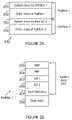
- FIG. 2Bshows a block diagram for Partition 1 , which is similar to Partition 2 .
- system area 201has various segments, for example, the master boot record (“MBR”) area 205 , partition boot record (“PBR”) area 206 , FAT 1 area 207 , FAT 2 area 208 and root directory area 209 .
- MLRmaster boot record
- PBRpartition boot record
- MBR area 205stores overall partition information, and if the media is a bootable device, then MBR 205 includes instructions to jump from MBR area 205 to PBR area 206 .
- MBR area 205also includes hidden area, which is reserved space between MBR area 205 and PBR area 206 .
- PBR area 206includes partition/boot information for a partition (in this example, Partition 1 ).
- PBR area 206includes information for the type of FAT (for example, 12/16/32 bits); a label (i.e. name of the drive), size of the drive; cluster size (i.e. the number of sectors per allocation unit); number of FAT areas (2 FAT areas FAT 1 and FAT 2 shown in FIG. 2B ) and the number of sectors per FAT.
- FAT areas( 207 and 208 ) contain cluster information for each file. For example, for FAT 12 , each entry in areas 207 and 208 contains 12 bits and there are a total of 4096 entries. Cluster 0 and 1 are reserved for 0XFFFFF8 (for media type) and End of Cluster. A particular cluster (for example, cluster 4087 ) is used to indicate bad clusters. For a FAT 16 , each entry contains 16 bits and for FAT 32 , each entry contains 32 bits.
- Root directory 209contains entries for each file.
- Each directory entryincludes a certain number of bytes for file name or directory (for example, 8 bytes); a number of bytes for extension (for example, 3 bytes), a number of bytes (for example, 1 byte) for file attributes (for example, if a file is read only, hidden, system file, volume label, directory or modified); a number of bytes indicating the time and date when a file was created; a certain number of bytes (for example 2) for a starting cluster; and a certain number of bytes (for example 4) indicating the file length.
- the number of bytes for the starting cluster points to the first cluster in FAT and the last clustermay be indicated by 0xFFF, 0xFFFF or 0Xffffff.
- the host systemfinds free cluster space in FAT 1 area 207 and data is written in data area 202 . Both FAT 1 and FAT 2 entries are then updated. The directory entry i.e., the date/time/starting cluster/file length is also updated.
- memory controller 150 Areallocates partition space when one partition becomes full or reaches a certain threshold value and the other partition has empty space. Thus one partition increases in size, while the other decreases.
- the threshold valuecan be programmed by memory controller 150 A.
- a mapping scheme(referred to herein as a “virtual map”) is used to track cluster usage in both the partitions, as described below. This entire process is performed efficiently by memory controller 150 A. The host system does not have to copy all the data and reformat the storage device.
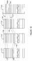
- FIG. 2Cshows the layout of the re-allocated Partition 1 and Partition 2 , as it appears to a host system.
- the system area 201 A of Partition 1includes updated cluster and partition information after the re-allocation.
- the original partition area 202is either full or has reached a threshold size where no more data is written there.
- the new data area 202 Ais allocated to Partition 1 from Partition 2 .
- the reduced Partition 2has a system area 203 A and a new reduced data area 204 A. The process for re-allocating the partitions will now be described in detail.
- FIG. 2Dshows the actual layout of Partition 1 and 2 after a re-allocation has been performed by memory controller 150 A.
- Partition 2 system area 203 Ais the adjusted area after area 202 A is allocated to partition A.
- Partition 2has data areas shown as 204 B and 204 C that are equal to data area 204 A, as shown in FIG. 2C .
- FIG. 3shows a top-level flow diagram for re-allocating partition sizes, according to one aspect of the present invention.
- the processbegins in step S 300 , when flash device 150 is initialized.
- controller 150 Adetermines if a partition is full. A partition is considered full when it can no longer store any more data or it has reached a certain threshold programmable value. If a partition is not full, then controller 150 A waits until a partition is full.
- step S 304controller 150 A determines if empty space is available from another partition (for example, Partition 2 ). If empty space is not available, then the process returns to step S 302 .
- step S 306If empty space is available, then in step S 306 , a certain amount of that empty space (for example, 202 A) is allocated to the full partition. After the re-allocation, FAT entries for both the partitions are adjusted in step S 308 , as described below in detail. The directory entries are also adjusted in step S 310 , also described below in detail, and the process ends in step S 312 .
- FIGS. 4A-4Fillustrate the foregoing process steps for re-allocating memory space between at least two memory partitions. It is noteworthy that the various values that are used in FIGS. 4A-4F are simply used as examples for illustration purposes only and are not intended to limit the adaptive aspects of the present invention.
- FIGS. 4A-4Fassumes that the cluster size in flash device 150 is 32 Kilo Bytes (KB), hence a 120 megabytes (MB) flash device has 4096 clusters.
- Each system area ( 201 and 203 )uses 6 clusters and each partition has a data area of 2042 clusters.
- Each clustermay be referred to as a block, i.e., one block size is equal to the cluster size.
- FIG. 4Ashows a table for the initial partition state (as shown in FIG. 2A ). Each partition has 6 blocks for system area and 2042 blocks for data area.
- Partition 1system area 201 is assigned block numbers 0 - 5 and data area 202 are assigned block numbers 6 - 2047 .
- system area 203is assigned blocks 2048 - 2053 and data area 204 is assigned block numbers 2054 - 4095 .
- FIG. 4Bshows an example of a mapping table 400 A with virtual block numbers in row 400 and real block numbers in row 401 .
- Column entries 402 - 409are self explanatory and provide virtual and real logical block numbers for the system areas, data areas that are used and empty data areas.
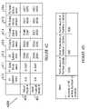
- FIG. 4Cshows an updated mapping table 400 B.
- the host system view( FIG. 2C ) is shown in row 400 and the real logical memory space view ( FIG. 2D ) is shown in row 401 .
- Partition 1The system area entries (shown in column 410 ) for Partition 1 in row 400 and 401 are the same. Column 411 shows that Partition 1 is full, i.e. all block 6 - 2047 are used. Partition 2 has some empty blocks (shown as 3001 - 4000 in FIG. 4B ) and 500 of those empty blocks are allocated to Partition 1 . The host sees these 500 blocks for Partition 1 to be from 2048 - 2547 , as shown in row 400 and column 414 , based on the virtual block number. Hence, for a host system, Partition 1 extends from block 0 to 2547 . In real Logical memory space as shown in FIG. 2D , the 500 blocks for Partition 1 are located at block numbers 3001 and 3500 (as shown in row 401 and column 414 , FIG. 4C ).
- Partition 2the host sees the system area for partition area to be contiguous, i.e., from 2548 - 2553 (shown in row 400 and column 412 ), when in reality, the system area is from 2048 - 2053 (see row 401 and column 412 ).
- the data blocks for the space used in Partition 2are shown in column 413 .
- the virtual block numbersare 2554 - 3500
- the real block numbersare from 2054 - 3000 (shown in row 401 and column 413 ).
- the entries for rows 400 and 401 and columns 415 and 416are the same.
- the hostdoes not copy data for re-allocating the partition space.
- the mapping table 400 ABy using and updating the mapping table 400 A, unused space is re-allocated to the full memory partition.
- the FAT table for Partition 1is not changed.
- the FAT entriesare adjusted to accommodate the area that is assigned to Partition 1 .
- data area B for Partition 2(shown as 204 C) will have its entries reduced by the data area that is assigned to Partition 1 .
- the starting cluster for each file name entry in data area B for Partition 2(shown as 204 C) will be adjusted by 500, if it is below data area A of Partition 2 (shown as 204 B).
- FIG. 4Dillustrates the foregoing example in a table format.
- Data area A for partition B(shown as 204 B in FIG. 2D ) has 1000 entries.
- Area 202 Ahas 500 entries and area 204 C has 500 entries.
- each partition of flash device 150publishes itself to the host to have certain capacity that is available for the partition. For example, if the flash device 150 is 4 GB, then each partition publishes itself to be 2 GB. Hence, it is desirable to have enough FAT area available for each partition so that it can accommodate the entire flash device space. This extra FAT table space allows the partition to grow. Hence, under memory controller 150 A, FAT 1 area 207 and FAT 2 area 208 are big enough to contain FAT entries for the entire flash memory device capacity.
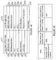
- FIG. 4Eshows a table with column 417 showing a host/user's view of a partition map and column 418 shows the actual/real partition map.
- the real partition mapincludes a reserved area 207 A for FAT area expansion. This area is big enough so that the FAT entries in FAT 1 and FAT 2 can accommodate the entire storage device.
- the reserved area 207 Ais used to provide the extra space for the expansion.
- the partition areasare re-allocated by memory controller 150 A, the FAT areas are adjusted to accommodate the change in partition size.
- the file name entries in the directory areaare also adjusted (step S 310 , FIG. 3 ) when the partition spaces are re-allocated by memory controller 150 A. Based on the foregoing example ( FIGS. 4A-4C ), the file name entry for Partition 1 is not changed. For Partition 2 , the starting cluster for the file name entry is adjusted to accommodate the area that is assigned to Partition 1 .
- data area B for Partition 2(shown as 204 C) will have its entries reduced by the data area that is assigned to Partition 1 .
- the starting cluster for each file name entry in data area B for Partition 2(shown as 204 C) will be adjusted by 500, if it is below data area A of Partition 2 (shown as 204 B).
- FIG. 4Fillustrates the foregoing example in a table format.
- Data area A for partition B(shown as 204 B in FIG. 2D ) has 1000 entries.
- Area 202 Ahas 500 entries and area 204 C has 500 entries.
- partition areasare re-allocated/adjusted by the memory device controller without copying all the data in a tedious time consuming operation.
- the host systemdoes not have to perform the time consuming process of copying/re-formatting the drives in order to re-allocate partition storage space.
Landscapes
- Engineering & Computer Science (AREA)
- Theoretical Computer Science (AREA)
- Physics & Mathematics (AREA)
- General Engineering & Computer Science (AREA)
- General Physics & Mathematics (AREA)
- Human Computer Interaction (AREA)
- Information Retrieval, Db Structures And Fs Structures Therefor (AREA)
- Memory System (AREA)
- Memory System Of A Hierarchy Structure (AREA)
Abstract
Description
Claims (17)
Priority Applications (11)
| Application Number | Priority Date | Filing Date | Title |
|---|---|---|---|
| US11/170,221US7457910B2 (en) | 2005-06-29 | 2005-06-29 | Method and system for managing partitions in a storage device |
| KR1020087001992AKR20080025178A (en) | 2005-06-29 | 2006-06-28 | Method and system for managing partitions on storage devices |
| EP06785898AEP1896931A2 (en) | 2005-06-29 | 2006-06-28 | Method and system for managing partitions in a storage device |
| TW095123352ATWI315032B (en) | 2005-06-29 | 2006-06-28 | Method and system for managing partitions in a storage device |
| CN2006800235956ACN101213510B (en) | 2005-06-29 | 2006-06-28 | Method and system for managing partitions in a storage device |
| EP09012265AEP2159681A3 (en) | 2005-06-29 | 2006-06-28 | Method and system for managing partitions in a storage device |
| EP10010262AEP2270643A1 (en) | 2005-06-29 | 2006-06-28 | Method and system for managing partitions in a storage device |
| PCT/US2006/025467WO2007002866A2 (en) | 2005-06-29 | 2006-06-28 | Method and system for managing partitions in a storage device |
| JP2008519586AJP5143730B2 (en) | 2005-06-29 | 2006-06-28 | Method and system for managing partitions in a storage device |
| US12/252,863US7853772B2 (en) | 2005-06-29 | 2008-10-16 | Method for managing partitions in a storage device |
| JP2012176609AJP2013012212A (en) | 2005-06-29 | 2012-08-09 | Method and system for managing partition in storage device |
Applications Claiming Priority (1)
| Application Number | Priority Date | Filing Date | Title |
|---|---|---|---|
| US11/170,221US7457910B2 (en) | 2005-06-29 | 2005-06-29 | Method and system for managing partitions in a storage device |
Related Child Applications (1)
| Application Number | Title | Priority Date | Filing Date |
|---|---|---|---|
| US12/252,863ContinuationUS7853772B2 (en) | 2005-06-29 | 2008-10-16 | Method for managing partitions in a storage device |
Publications (2)
| Publication Number | Publication Date |
|---|---|
| US20070002612A1 US20070002612A1 (en) | 2007-01-04 |
| US7457910B2true US7457910B2 (en) | 2008-11-25 |
Family
ID=37101969
Family Applications (2)
| Application Number | Title | Priority Date | Filing Date |
|---|---|---|---|
| US11/170,221Active2025-12-15US7457910B2 (en) | 2005-06-29 | 2005-06-29 | Method and system for managing partitions in a storage device |
| US12/252,863Expired - LifetimeUS7853772B2 (en) | 2005-06-29 | 2008-10-16 | Method for managing partitions in a storage device |
Family Applications After (1)
| Application Number | Title | Priority Date | Filing Date |
|---|---|---|---|
| US12/252,863Expired - LifetimeUS7853772B2 (en) | 2005-06-29 | 2008-10-16 | Method for managing partitions in a storage device |
Country Status (7)
| Country | Link |
|---|---|
| US (2) | US7457910B2 (en) |
| EP (3) | EP2270643A1 (en) |
| JP (2) | JP5143730B2 (en) |
| KR (1) | KR20080025178A (en) |
| CN (1) | CN101213510B (en) |
| TW (1) | TWI315032B (en) |
| WO (1) | WO2007002866A2 (en) |
Cited By (21)
| Publication number | Priority date | Publication date | Assignee | Title |
|---|---|---|---|---|
| US20050050092A1 (en)* | 2003-08-25 | 2005-03-03 | Oracle International Corporation | Direct loading of semistructured data |
| US20080082725A1 (en)* | 2006-09-28 | 2008-04-03 | Reuven Elhamias | End of Life Recovery and Resizing of Memory Cards |
| US20080082726A1 (en)* | 2006-09-28 | 2008-04-03 | Reuven Elhamias | Memory Cards with End of Life Recovery and Resizing |
| US20090138887A1 (en)* | 2007-11-28 | 2009-05-28 | Hitachi, Ltd. | Virtual machine monitor and multiprocessor sysyem |
| US20090210464A1 (en)* | 2008-02-18 | 2009-08-20 | Hon Hai Precision Industry Co., Ltd. | Storage management system and method thereof |
| US20090271581A1 (en)* | 2008-04-24 | 2009-10-29 | Echostar Technologies Corporation | Systems and methods for reliably managing files in a computer system |
| US20090313418A1 (en)* | 2008-06-11 | 2009-12-17 | International Business Machines Corporation | Using asymmetric memory |
| US20100161891A1 (en)* | 2006-01-25 | 2010-06-24 | Takashi Oshima | Method of controlling card-shaped memory device |
| US7747580B2 (en) | 2003-08-25 | 2010-06-29 | Oracle International Corporation | Direct loading of opaque types |
| US20100174860A1 (en)* | 2009-01-07 | 2010-07-08 | Min-Chan Kim | Non-volatile memory, page dynamic allocation apparatus and page mapping apparatus therefor, and page dynamic allocation method and page mapping method therefor |
| US20100191779A1 (en)* | 2009-01-27 | 2010-07-29 | EchoStar Technologies, L.L.C. | Systems and methods for managing files on a storage device |
| US20100318760A1 (en)* | 2008-01-30 | 2010-12-16 | Hirokazu So | Memory controller, nonvolatile storage device, and nonvolatile storage system |
| US7933928B2 (en)* | 2005-12-22 | 2011-04-26 | Oracle International Corporation | Method and mechanism for loading XML documents into memory |
| US7933935B2 (en) | 2006-10-16 | 2011-04-26 | Oracle International Corporation | Efficient partitioning technique while managing large XML documents |
| US20120089805A1 (en)* | 2010-10-08 | 2012-04-12 | Phison Electronics Corp. | Memory storage device, memory controller thereof, and method for automatically creating fill-file thereof |
| US8429196B2 (en) | 2008-06-06 | 2013-04-23 | Oracle International Corporation | Fast extraction of scalar values from binary encoded XML |
| US20140372676A1 (en)* | 2013-06-14 | 2014-12-18 | Samsung Electronics Co., Ltd. | Electronic device and method for mounting file system using virtual block device |
| US20150189778A1 (en)* | 2013-12-27 | 2015-07-02 | Brother Kogyo Kabushiki Kaisha | Sheet processing apparatus |
| US9268646B1 (en)* | 2010-12-21 | 2016-02-23 | Western Digital Technologies, Inc. | System and method for optimized management of operation data in a solid-state memory |
| US9361044B2 (en) | 2011-03-28 | 2016-06-07 | Western Digital Technologies, Inc. | Power-safe data management system |
| US20170357449A1 (en)* | 2016-06-09 | 2017-12-14 | Apple Inc. | Managing Data Using a Time-Based Directory Structure |
Families Citing this family (107)
| Publication number | Priority date | Publication date | Assignee | Title |
|---|---|---|---|---|
| JP4428200B2 (en)* | 2004-11-01 | 2010-03-10 | ソニー株式会社 | Information recording apparatus and method, program storage medium, and program |
| US8010753B2 (en)* | 2005-09-28 | 2011-08-30 | International Business Machines Corporation | Systems and methods for temporarily transferring use of portions of partitioned memory between host computers |
| KR100714709B1 (en)* | 2006-01-11 | 2007-05-04 | 삼성전자주식회사 | Hidden Zone Management Devices and Methods |
| US7971071B2 (en)* | 2006-05-24 | 2011-06-28 | Walkoe Wilbur J | Integrated delivery and protection device for digital objects |
| US8489817B2 (en) | 2007-12-06 | 2013-07-16 | Fusion-Io, Inc. | Apparatus, system, and method for caching data |
| US8019938B2 (en) | 2006-12-06 | 2011-09-13 | Fusion-I0, Inc. | Apparatus, system, and method for solid-state storage as cache for high-capacity, non-volatile storage |
| US7966355B2 (en)* | 2007-02-13 | 2011-06-21 | Modu Ltd. | Interface for extending functionality of memory cards |
| US7917479B2 (en)* | 2007-03-20 | 2011-03-29 | Micron Technology, Inc. | Non-volatile memory devices, systems including same and associated methods |
| US8429352B2 (en) | 2007-06-08 | 2013-04-23 | Sandisk Technologies Inc. | Method and system for memory block flushing |
| US9693106B2 (en)* | 2007-07-26 | 2017-06-27 | The Directv Group, Inc. | Method and system for preordering content in a user device associated with a content processing system |
| KR101433859B1 (en)* | 2007-10-12 | 2014-08-27 | 삼성전자주식회사 | Nonvolatile memory system and method managing file data thereof |
| US8162227B2 (en) | 2007-11-12 | 2012-04-24 | Micron Technology, Inc. | Intelligent controller system and method for smart card memory modules |
| US8156322B2 (en) | 2007-11-12 | 2012-04-10 | Micron Technology, Inc. | Critical security parameter generation and exchange system and method for smart-card memory modules |
| US8898477B2 (en)* | 2007-11-12 | 2014-11-25 | Gemalto Inc. | System and method for secure firmware update of a secure token having a flash memory controller and a smart card |
| US8286883B2 (en) | 2007-11-12 | 2012-10-16 | Micron Technology, Inc. | System and method for updating read-only memory in smart card memory modules |
| US8307131B2 (en)* | 2007-11-12 | 2012-11-06 | Gemalto Sa | System and method for drive resizing and partition size exchange between a flash memory controller and a smart card |
| US7836226B2 (en) | 2007-12-06 | 2010-11-16 | Fusion-Io, Inc. | Apparatus, system, and method for coordinating storage requests in a multi-processor/multi-thread environment |
| US9519540B2 (en) | 2007-12-06 | 2016-12-13 | Sandisk Technologies Llc | Apparatus, system, and method for destaging cached data |
| US8583878B2 (en)* | 2008-01-02 | 2013-11-12 | Sandisk Il Ltd. | Storage device having direct user access |
| US8452927B2 (en)* | 2008-01-02 | 2013-05-28 | Sandisk Technologies Inc. | Distributed storage service systems and architecture |
| US9098506B2 (en)* | 2008-01-02 | 2015-08-04 | Sandisk Il, Ltd. | Data indexing by local storage device |
| US8370402B2 (en)* | 2008-01-02 | 2013-02-05 | Sandisk Il Ltd | Dual representation of stored digital content |
| US20100122039A1 (en)* | 2008-11-11 | 2010-05-13 | Ravi Ranjan Kumar | Memory Systems and Accessing Methods |
| US8880776B2 (en)* | 2008-12-16 | 2014-11-04 | Sandisk Il Ltd. | Data access at a storage device using cluster information |
| JP5218024B2 (en)* | 2008-12-22 | 2013-06-26 | 株式会社リコー | Information processing apparatus, information processing method, and information processing program |
| US7974190B2 (en)* | 2009-02-12 | 2011-07-05 | Micrel, Inc. | Dynamic queue memory allocation with flow control |
| US8370645B2 (en) | 2009-03-03 | 2013-02-05 | Micron Technology, Inc. | Protection of security parameters in storage devices |
| CN101908009B (en)* | 2009-06-08 | 2014-02-19 | 鸿富锦精密工业(深圳)有限公司 | File Backup and Usage |
| JP5999645B2 (en) | 2009-09-08 | 2016-10-05 | ロンギチュード エンタープライズ フラッシュ エスエイアールエル | Apparatus, system, and method for caching data on a solid state storage device |
| US9122579B2 (en) | 2010-01-06 | 2015-09-01 | Intelligent Intellectual Property Holdings 2 Llc | Apparatus, system, and method for a storage layer |
| KR101769883B1 (en) | 2009-09-09 | 2017-08-21 | 샌디스크 테크놀로지스 엘엘씨 | Apparatus, system, and method for allocating storage |
| TWI395102B (en)* | 2009-10-02 | 2013-05-01 | Via Tech Inc | Data storage device and method |
| CN101662706B (en)* | 2009-10-20 | 2013-03-20 | 国家电网公司 | Service memorizing method and module thereof |
| US8391302B1 (en)* | 2009-12-03 | 2013-03-05 | Integrated Device Technology, Inc. | High-performance ingress buffer for a packet switch |
| CN101808123B (en)* | 2010-03-09 | 2013-04-17 | 浪潮(北京)电子信息产业有限公司 | Method and device for accessing storage resources in storage system |
| CN101868049B (en)* | 2010-06-03 | 2013-12-04 | 华为终端有限公司 | Communication methods for host and wireless Internet access module and host communication module |
| CN101938848B (en)* | 2010-06-03 | 2013-01-02 | 华为终端有限公司 | Host computer equipment wireless network access method and system |
| EP2563091B1 (en) | 2010-04-23 | 2016-06-08 | Huawei Device Co., Ltd. | Wireless internet-accessing module, host, communication method thereof, and data card |
| MX2012013459A (en) | 2010-05-19 | 2013-04-29 | Directv Group Inc | Method and system of building a wanted list queue for a user in a content distribution system. |
| US9456247B1 (en) | 2010-05-19 | 2016-09-27 | The Directv Group, Inc. | Method and system for changing communication parameters of a content delivery system based on feedback from user devices |
| US9883242B1 (en)* | 2010-05-19 | 2018-01-30 | The Directv Group, Inc. | Method and system for controlling a storage location of content in a user device |
| US20120017052A1 (en)* | 2010-07-19 | 2012-01-19 | Sauber William F | Information Handling System Universal Memory Wear Leveling System and Method |
| US20120239860A1 (en) | 2010-12-17 | 2012-09-20 | Fusion-Io, Inc. | Apparatus, system, and method for persistent data management on a non-volatile storage media |
| CN102541744B (en)* | 2010-12-24 | 2015-12-02 | 安凯(广州)微电子技术有限公司 | A kind of partition method of movable storage device and system |
| US8874823B2 (en) | 2011-02-15 | 2014-10-28 | Intellectual Property Holdings 2 Llc | Systems and methods for managing data input/output operations |
| US9003104B2 (en) | 2011-02-15 | 2015-04-07 | Intelligent Intellectual Property Holdings 2 Llc | Systems and methods for a file-level cache |
| US9201677B2 (en) | 2011-05-23 | 2015-12-01 | Intelligent Intellectual Property Holdings 2 Llc | Managing data input/output operations |
| WO2012116369A2 (en) | 2011-02-25 | 2012-08-30 | Fusion-Io, Inc. | Apparatus, system, and method for managing contents of a cache |
| US9563555B2 (en) | 2011-03-18 | 2017-02-07 | Sandisk Technologies Llc | Systems and methods for storage allocation |
| US8966191B2 (en) | 2011-03-18 | 2015-02-24 | Fusion-Io, Inc. | Logical interface for contextual storage |
| FR2979443B1 (en)* | 2011-08-30 | 2013-09-27 | Maxim Integrated Products | SECURE MICROCONTROLLER BASED ON FASHION |
| US8856440B2 (en) | 2011-09-12 | 2014-10-07 | Microsoft Corporation | Volatile memory representation of nonvolatile storage device set |
| WO2013057532A1 (en)* | 2011-10-21 | 2013-04-25 | Freescale Semiconductor, Inc. | Memory device and method for organizing a homogeneous memory |
| US9274937B2 (en) | 2011-12-22 | 2016-03-01 | Longitude Enterprise Flash S.A.R.L. | Systems, methods, and interfaces for vector input/output operations |
| US9251086B2 (en) | 2012-01-24 | 2016-02-02 | SanDisk Technologies, Inc. | Apparatus, system, and method for managing a cache |
| US10359972B2 (en) | 2012-08-31 | 2019-07-23 | Sandisk Technologies Llc | Systems, methods, and interfaces for adaptive persistence |
| US9116812B2 (en) | 2012-01-27 | 2015-08-25 | Intelligent Intellectual Property Holdings 2 Llc | Systems and methods for a de-duplication cache |
| TWI489272B (en)* | 2012-04-03 | 2015-06-21 | Phison Electronics Corp | Data protecting method, and memory controller and memory storage device using the same |
| CN103377149B (en)* | 2012-04-16 | 2016-05-11 | 群联电子股份有限公司 | Method for protecting data, memory controller and memory storage device |
| US10339056B2 (en) | 2012-07-03 | 2019-07-02 | Sandisk Technologies Llc | Systems, methods and apparatus for cache transfers |
| US9612966B2 (en) | 2012-07-03 | 2017-04-04 | Sandisk Technologies Llc | Systems, methods and apparatus for a virtual machine cache |
| CN102789425B (en)* | 2012-07-17 | 2016-01-20 | 上海金智晟东电力科技有限公司 | Based on the file read/write method of FLASH storage medium |
| US10509776B2 (en) | 2012-09-24 | 2019-12-17 | Sandisk Technologies Llc | Time sequence data management |
| US10318495B2 (en) | 2012-09-24 | 2019-06-11 | Sandisk Technologies Llc | Snapshots for a non-volatile device |
| US10057726B2 (en)* | 2012-10-02 | 2018-08-21 | Razer (Asia-Pacific) Pte. Ltd. | Managing user data on an electronic device |
| KR101782302B1 (en)* | 2012-10-12 | 2017-09-26 | 에이나인.컴, 인크. | Index configuration for searchable data in network |
| US9507750B2 (en) | 2012-10-12 | 2016-11-29 | A9.Com, Inc. | Dynamic search partitioning |
| US9235377B2 (en)* | 2013-03-12 | 2016-01-12 | Invensense, Inc. | Multiple, per sensor configurable FIFOs in a single static random access memory (SRAM) structure |
| US9842053B2 (en) | 2013-03-15 | 2017-12-12 | Sandisk Technologies Llc | Systems and methods for persistent cache logging |
| US10558561B2 (en) | 2013-04-16 | 2020-02-11 | Sandisk Technologies Llc | Systems and methods for storage metadata management |
| US10102144B2 (en) | 2013-04-16 | 2018-10-16 | Sandisk Technologies Llc | Systems, methods and interfaces for data virtualization |
| CN104238953A (en)* | 2013-06-13 | 2014-12-24 | 中兴通讯股份有限公司 | Direct table storage method and device |
| US9842128B2 (en) | 2013-08-01 | 2017-12-12 | Sandisk Technologies Llc | Systems and methods for atomic storage operations |
| KR102088403B1 (en) | 2013-08-08 | 2020-03-13 | 삼성전자 주식회사 | Storage device, computer system comprising the same, and operating method thereof |
| US10019320B2 (en) | 2013-10-18 | 2018-07-10 | Sandisk Technologies Llc | Systems and methods for distributed atomic storage operations |
| US10073630B2 (en) | 2013-11-08 | 2018-09-11 | Sandisk Technologies Llc | Systems and methods for log coordination |
| KR20150138528A (en)* | 2014-05-29 | 2015-12-10 | 삼성전자주식회사 | Storage system based on flash memory and operation method thereof |
| US9846567B2 (en)* | 2014-06-16 | 2017-12-19 | International Business Machines Corporation | Flash optimized columnar data layout and data access algorithms for big data query engines |
| US10667008B1 (en) | 2014-12-18 | 2020-05-26 | The Directv Group, Inc. | Method and system for setting and receiving user notifications for content available far in the future |
| US9946607B2 (en) | 2015-03-04 | 2018-04-17 | Sandisk Technologies Llc | Systems and methods for storage error management |
| US9952808B2 (en) | 2015-03-26 | 2018-04-24 | International Business Machines Corporation | File system block-level tiering and co-allocation |
| JP6601077B2 (en)* | 2015-09-10 | 2019-11-06 | 富士通株式会社 | Information processing apparatus, log recording method, and log recording program |
| JP6380320B2 (en)* | 2015-09-29 | 2018-08-29 | 京セラドキュメントソリューションズ株式会社 | Electronic device, information processing method and program |
| US10348567B2 (en)* | 2015-10-15 | 2019-07-09 | Microsoft Technology Licensing, Llc | Mapping user identifiers between different device ecosystems |
| US10210298B2 (en)* | 2015-11-24 | 2019-02-19 | Altera Corporation | Embedded memory blocks with adjustable memory boundaries |
| EP3408623A4 (en)* | 2016-01-22 | 2020-01-15 | Illinois Tool Works, Inc. | Systems and methods to dynamically configure data values stored on a mass flow controller |
| US10261707B1 (en)* | 2016-03-24 | 2019-04-16 | Marvell International Ltd. | Decoder memory sharing |
| US10152237B2 (en) | 2016-05-05 | 2018-12-11 | Micron Technology, Inc. | Non-deterministic memory protocol |
| US10534540B2 (en) | 2016-06-06 | 2020-01-14 | Micron Technology, Inc. | Memory protocol |
| JP6783645B2 (en)* | 2016-12-21 | 2020-11-11 | キオクシア株式会社 | Memory system and control method |
| US20180292991A1 (en)* | 2017-04-11 | 2018-10-11 | Micron Technology, Inc. | Memory protocol with programmable buffer and cache size |
| KR20190006680A (en)* | 2017-07-11 | 2019-01-21 | 에스케이하이닉스 주식회사 | Data storage device and operating method thereof |
| CN109697016B (en)* | 2017-10-20 | 2022-02-15 | 伊姆西Ip控股有限责任公司 | Method and apparatus for improving storage performance of containers |
| US10908832B2 (en) | 2017-10-31 | 2021-02-02 | Micron Technology, Inc. | Common pool management |
| US10901911B2 (en)* | 2018-11-21 | 2021-01-26 | Microsoft Technology Licensing, Llc | Faster computer memory access by reducing SLAT fragmentation |
| CN109815711B (en)* | 2018-12-21 | 2020-12-25 | 航天信息股份有限公司 | Storage device, data storage method and data reading method |
| US10977174B2 (en)* | 2018-12-31 | 2021-04-13 | Micron Technology, Inc. | Using a common pool of blocks for user data and a system data structure |
| CN111274160A (en)* | 2020-01-22 | 2020-06-12 | 维沃移动通信有限公司 | Data storage method, electronic device, and medium |
| US11436153B2 (en)* | 2020-05-26 | 2022-09-06 | Western Digital Technologies, Inc. | Moving change log tables to align to zones |
| US20220019370A1 (en)* | 2020-07-16 | 2022-01-20 | Micron Technology, Inc. | Partial zone memory unit handling in a zoned namespace of a memory device |
| CN114879900A (en)* | 2021-02-05 | 2022-08-09 | 华为技术有限公司 | Log file processing method and device |
| US11537293B2 (en)* | 2021-02-18 | 2022-12-27 | Western Digital Technologies, Inc. | Wear leveling methods for zoned namespace solid state drive |
| CN114237514A (en)* | 2021-12-24 | 2022-03-25 | 深圳市宝佳乐电子科技有限公司 | Block management method, memory controller and memory storage device |
| US12353744B2 (en)* | 2022-01-14 | 2025-07-08 | SanDisk Technologies, Inc. | Cold storage partition management in proof of space blockchain systems |
| US12260131B2 (en) | 2023-05-02 | 2025-03-25 | SanDisk Technologies, Inc. | Commands splitting based on flat logical block address and security key |
| US12353757B2 (en)* | 2023-05-09 | 2025-07-08 | SanDisk Technologies, Inc. | Excess CMB utilization by storage controller |
| CN117632040B (en)* | 2024-01-25 | 2024-04-30 | 合肥兆芯电子有限公司 | Data writing method, memory storage device and memory control circuit unit |
Citations (24)
| Publication number | Priority date | Publication date | Assignee | Title |
|---|---|---|---|---|
| US5193184A (en) | 1990-06-18 | 1993-03-09 | Storage Technology Corporation | Deleted data file space release system for a dynamically mapped virtual data storage subsystem |
| US5253344A (en) | 1991-09-05 | 1993-10-12 | International Business Machines Corp. | Method and apparatus for dynamically changing the configuration of a logically partitioned data processing system |
| US5570315A (en) | 1993-09-21 | 1996-10-29 | Kabushiki Kaisha Toshiba | Multi-state EEPROM having write-verify control circuit |
| US5602987A (en) | 1989-04-13 | 1997-02-11 | Sandisk Corporation | Flash EEprom system |
| US5659786A (en) | 1992-10-19 | 1997-08-19 | International Business Machines Corporation | System and method for dynamically performing resource reconfiguration in a logically partitioned data processing system |
| US5774397A (en) | 1993-06-29 | 1998-06-30 | Kabushiki Kaisha Toshiba | Non-volatile semiconductor memory device and method of programming a non-volatile memory cell to a predetermined state |
| WO1999057641A1 (en) | 1998-05-01 | 1999-11-11 | Powerquest Corporation | Manipulation of virtual and live computer storage device partitions |
| US6046935A (en) | 1996-03-18 | 2000-04-04 | Kabushiki Kaisha Toshiba | Semiconductor device and memory system |
| USRE36989E (en) | 1979-10-18 | 2000-12-12 | Storage Technology Corporation | Virtual storage system and method |
| US6373746B1 (en) | 1999-09-28 | 2002-04-16 | Kabushiki Kaisha Toshiba | Nonvolatile semiconductor memory having plural data storage portions for a bit line connected to memory cells |
| US6426893B1 (en) | 2000-02-17 | 2002-07-30 | Sandisk Corporation | Flash eeprom system with simultaneous multiple data sector programming and storage of physical block characteristics in other designated blocks |
| US6456528B1 (en) | 2001-09-17 | 2002-09-24 | Sandisk Corporation | Selective operation of a multi-state non-volatile memory system in a binary mode |
| US6522580B2 (en) | 2001-06-27 | 2003-02-18 | Sandisk Corporation | Operating techniques for reducing effects of coupling between storage elements of a non-volatile memory operated in multiple data states |
| US20030061457A1 (en)* | 2000-04-14 | 2003-03-27 | Interactive Silicon, Incorporated | Managing a codec engine for memory compression / decompression operations using a data movement engine |
| US6609187B1 (en) | 1999-07-06 | 2003-08-19 | Dell Products L.P. | Method and apparatus for supporting resizing of file system partitions |
| US20030158884A1 (en)* | 2002-02-21 | 2003-08-21 | International Business Machines Corporation | Apparatus and method of dynamically repartitioning a computer system in response to partition workloads |
| US6643188B2 (en) | 2001-12-27 | 2003-11-04 | Kabushiki Kaisha Toshiba | Non-volatile semiconductor memory device adapted to store a multi-valued data in a single memory cell |
| US6694419B1 (en) | 2002-04-12 | 2004-02-17 | Barsa Consulting Group, Llc | Method and system for automatically measuring partition memory needs in a partitioned computer system |
| US20040139287A1 (en) | 2003-01-09 | 2004-07-15 | International Business Machines Corporation | Method, system, and computer program product for creating and managing memory affinity in logically partitioned data processing systems |
| US6771536B2 (en) | 2002-02-27 | 2004-08-03 | Sandisk Corporation | Operating techniques for reducing program and read disturbs of a non-volatile memory |
| US6781877B2 (en) | 2002-09-06 | 2004-08-24 | Sandisk Corporation | Techniques for reducing effects of coupling between storage elements of adjacent rows of memory cells |
| US6851030B2 (en) | 2002-10-16 | 2005-02-01 | International Business Machines Corporation | System and method for dynamically allocating associative resources |
| US20060031593A1 (en)* | 2004-08-09 | 2006-02-09 | Sinclair Alan W | Ring bus structure and its use in flash memory systems |
| US20060106972A1 (en)* | 2004-11-15 | 2006-05-18 | Gorobets Sergey A | Cyclic flash memory wear leveling |
Family Cites Families (13)
| Publication number | Priority date | Publication date | Assignee | Title |
|---|---|---|---|---|
| JPH0581091A (en)* | 1991-09-19 | 1993-04-02 | Fuji Xerox Co Ltd | Data processor |
| US5706472A (en)* | 1995-02-23 | 1998-01-06 | Powerquest Corporation | Method for manipulating disk partitions |
| US5675769A (en)* | 1995-02-23 | 1997-10-07 | Powerquest Corporation | Method for manipulating disk partitions |
| JPH08314773A (en)* | 1995-05-15 | 1996-11-29 | Nec Corp | Divided area relocation system for storage device |
| JP3613052B2 (en)* | 1999-02-09 | 2005-01-26 | 日本電気株式会社 | Computer-readable recording medium on which an operating system is recorded |
| JP3942807B2 (en)* | 2000-06-06 | 2007-07-11 | 株式会社ルネサステクノロジ | Semiconductor memory device with block alignment function |
| JP2002222061A (en)* | 2001-01-25 | 2002-08-09 | Hitachi Ltd | Method of setting storage area, storage device, and program storage medium |
| JP2003085014A (en)* | 2001-09-12 | 2003-03-20 | Toshiba Corp | Network system volume management method and computer |
| TWI240861B (en)* | 2002-01-11 | 2005-10-01 | Integrated Circuit Solution In | Data access method and architecture of flash memory |
| US7653796B2 (en)* | 2003-02-20 | 2010-01-26 | Panasonic Corporation | Information recording medium and region management method for a plurality of recording regions each managed by independent file system |
| US7305520B2 (en)* | 2004-01-30 | 2007-12-04 | Hewlett-Packard Development Company, L.P. | Storage system with capability to allocate virtual storage segments among a plurality of controllers |
| US8607016B2 (en)* | 2004-07-21 | 2013-12-10 | Sandisk Technologies Inc. | FAT analysis for optimized sequential cluster management |
| US7496493B1 (en)* | 2004-11-09 | 2009-02-24 | Western Digital Technologies, Inc. | External memory device to provide disk device and optical functionality |
- 2005
- 2005-06-29USUS11/170,221patent/US7457910B2/enactiveActive
- 2006
- 2006-06-28EPEP10010262Apatent/EP2270643A1/ennot_activeWithdrawn
- 2006-06-28TWTW095123352Apatent/TWI315032B/ennot_activeIP Right Cessation
- 2006-06-28EPEP09012265Apatent/EP2159681A3/ennot_activeWithdrawn
- 2006-06-28JPJP2008519586Apatent/JP5143730B2/ennot_activeExpired - Fee Related
- 2006-06-28WOPCT/US2006/025467patent/WO2007002866A2/enactiveApplication Filing
- 2006-06-28KRKR1020087001992Apatent/KR20080025178A/ennot_activeAbandoned
- 2006-06-28CNCN2006800235956Apatent/CN101213510B/ennot_activeExpired - Fee Related
- 2006-06-28EPEP06785898Apatent/EP1896931A2/ennot_activeCeased
- 2008
- 2008-10-16USUS12/252,863patent/US7853772B2/ennot_activeExpired - Lifetime
- 2012
- 2012-08-09JPJP2012176609Apatent/JP2013012212A/ennot_activeCeased
Patent Citations (26)
| Publication number | Priority date | Publication date | Assignee | Title |
|---|---|---|---|---|
| USRE36989E (en) | 1979-10-18 | 2000-12-12 | Storage Technology Corporation | Virtual storage system and method |
| US5602987A (en) | 1989-04-13 | 1997-02-11 | Sandisk Corporation | Flash EEprom system |
| US5193184A (en) | 1990-06-18 | 1993-03-09 | Storage Technology Corporation | Deleted data file space release system for a dynamically mapped virtual data storage subsystem |
| US5253344A (en) | 1991-09-05 | 1993-10-12 | International Business Machines Corp. | Method and apparatus for dynamically changing the configuration of a logically partitioned data processing system |
| US5659786A (en) | 1992-10-19 | 1997-08-19 | International Business Machines Corporation | System and method for dynamically performing resource reconfiguration in a logically partitioned data processing system |
| US5784702A (en) | 1992-10-19 | 1998-07-21 | Internatinal Business Machines Corporation | System and method for dynamically performing resource reconfiguration in a logically partitioned data processing system |
| US5774397A (en) | 1993-06-29 | 1998-06-30 | Kabushiki Kaisha Toshiba | Non-volatile semiconductor memory device and method of programming a non-volatile memory cell to a predetermined state |
| US5570315A (en) | 1993-09-21 | 1996-10-29 | Kabushiki Kaisha Toshiba | Multi-state EEPROM having write-verify control circuit |
| US6046935A (en) | 1996-03-18 | 2000-04-04 | Kabushiki Kaisha Toshiba | Semiconductor device and memory system |
| WO1999057641A1 (en) | 1998-05-01 | 1999-11-11 | Powerquest Corporation | Manipulation of virtual and live computer storage device partitions |
| US6609187B1 (en) | 1999-07-06 | 2003-08-19 | Dell Products L.P. | Method and apparatus for supporting resizing of file system partitions |
| US6373746B1 (en) | 1999-09-28 | 2002-04-16 | Kabushiki Kaisha Toshiba | Nonvolatile semiconductor memory having plural data storage portions for a bit line connected to memory cells |
| US6426893B1 (en) | 2000-02-17 | 2002-07-30 | Sandisk Corporation | Flash eeprom system with simultaneous multiple data sector programming and storage of physical block characteristics in other designated blocks |
| US20030061457A1 (en)* | 2000-04-14 | 2003-03-27 | Interactive Silicon, Incorporated | Managing a codec engine for memory compression / decompression operations using a data movement engine |
| US6522580B2 (en) | 2001-06-27 | 2003-02-18 | Sandisk Corporation | Operating techniques for reducing effects of coupling between storage elements of a non-volatile memory operated in multiple data states |
| US6456528B1 (en) | 2001-09-17 | 2002-09-24 | Sandisk Corporation | Selective operation of a multi-state non-volatile memory system in a binary mode |
| US6643188B2 (en) | 2001-12-27 | 2003-11-04 | Kabushiki Kaisha Toshiba | Non-volatile semiconductor memory device adapted to store a multi-valued data in a single memory cell |
| US20030158884A1 (en)* | 2002-02-21 | 2003-08-21 | International Business Machines Corporation | Apparatus and method of dynamically repartitioning a computer system in response to partition workloads |
| US6771536B2 (en) | 2002-02-27 | 2004-08-03 | Sandisk Corporation | Operating techniques for reducing program and read disturbs of a non-volatile memory |
| US6694419B1 (en) | 2002-04-12 | 2004-02-17 | Barsa Consulting Group, Llc | Method and system for automatically measuring partition memory needs in a partitioned computer system |
| US6742100B1 (en) | 2002-04-12 | 2004-05-25 | Barsa Consulting Group, Llc | Method and system for managing memory pools in a partitioned computer system |
| US6781877B2 (en) | 2002-09-06 | 2004-08-24 | Sandisk Corporation | Techniques for reducing effects of coupling between storage elements of adjacent rows of memory cells |
| US6851030B2 (en) | 2002-10-16 | 2005-02-01 | International Business Machines Corporation | System and method for dynamically allocating associative resources |
| US20040139287A1 (en) | 2003-01-09 | 2004-07-15 | International Business Machines Corporation | Method, system, and computer program product for creating and managing memory affinity in logically partitioned data processing systems |
| US20060031593A1 (en)* | 2004-08-09 | 2006-02-09 | Sinclair Alan W | Ring bus structure and its use in flash memory systems |
| US20060106972A1 (en)* | 2004-11-15 | 2006-05-18 | Gorobets Sergey A | Cyclic flash memory wear leveling |
Non-Patent Citations (2)
| Title |
|---|
| International Search Report on corresponding PCT application (PCT/US2006/025467) from International Searching Authority (EPO) dated Feb. 15, 2007. |
| Written Opinion on corresponding PCT application (PCT/US2006/025467) from International Searching Authority (EPO) dated Feb. 15, 2007. |
Cited By (36)
| Publication number | Priority date | Publication date | Assignee | Title |
|---|---|---|---|---|
| US7747580B2 (en) | 2003-08-25 | 2010-06-29 | Oracle International Corporation | Direct loading of opaque types |
| US20050050092A1 (en)* | 2003-08-25 | 2005-03-03 | Oracle International Corporation | Direct loading of semistructured data |
| US7814047B2 (en) | 2003-08-25 | 2010-10-12 | Oracle International Corporation | Direct loading of semistructured data |
| US7933928B2 (en)* | 2005-12-22 | 2011-04-26 | Oracle International Corporation | Method and mechanism for loading XML documents into memory |
| US7917690B2 (en)* | 2006-01-25 | 2011-03-29 | Kabushiki Kaisha Toshiba | Method of controlling card-shaped memory device |
| US20100161891A1 (en)* | 2006-01-25 | 2010-06-24 | Takashi Oshima | Method of controlling card-shaped memory device |
| US20080082726A1 (en)* | 2006-09-28 | 2008-04-03 | Reuven Elhamias | Memory Cards with End of Life Recovery and Resizing |
| US7596656B2 (en)* | 2006-09-28 | 2009-09-29 | Sandisk Corporation | Memory cards with end of life recovery and resizing |
| US20080082725A1 (en)* | 2006-09-28 | 2008-04-03 | Reuven Elhamias | End of Life Recovery and Resizing of Memory Cards |
| US7933935B2 (en) | 2006-10-16 | 2011-04-26 | Oracle International Corporation | Efficient partitioning technique while managing large XML documents |
| US20090138887A1 (en)* | 2007-11-28 | 2009-05-28 | Hitachi, Ltd. | Virtual machine monitor and multiprocessor sysyem |
| US8819675B2 (en)* | 2007-11-28 | 2014-08-26 | Hitachi, Ltd. | Virtual machine monitor and multiprocessor system |
| US20100318760A1 (en)* | 2008-01-30 | 2010-12-16 | Hirokazu So | Memory controller, nonvolatile storage device, and nonvolatile storage system |
| US20090210464A1 (en)* | 2008-02-18 | 2009-08-20 | Hon Hai Precision Industry Co., Ltd. | Storage management system and method thereof |
| US9235473B2 (en) | 2008-04-24 | 2016-01-12 | Echostar Technologies L.L.C. | Systems and methods for reliably managing files in a computer system |
| US20090271581A1 (en)* | 2008-04-24 | 2009-10-29 | Echostar Technologies Corporation | Systems and methods for reliably managing files in a computer system |
| US8271751B2 (en) | 2008-04-24 | 2012-09-18 | Echostar Technologies L.L.C. | Systems and methods for reliably managing files in a computer system |
| US8429196B2 (en) | 2008-06-06 | 2013-04-23 | Oracle International Corporation | Fast extraction of scalar values from binary encoded XML |
| US8065304B2 (en)* | 2008-06-11 | 2011-11-22 | International Business Machines Corporation | Using asymmetric memory |
| US20090313418A1 (en)* | 2008-06-11 | 2009-12-17 | International Business Machines Corporation | Using asymmetric memory |
| US20100174860A1 (en)* | 2009-01-07 | 2010-07-08 | Min-Chan Kim | Non-volatile memory, page dynamic allocation apparatus and page mapping apparatus therefor, and page dynamic allocation method and page mapping method therefor |
| US8375191B2 (en) | 2009-01-07 | 2013-02-12 | Samsung Electronics Co., Ltd. | Non-volatile memory, page dynamic allocation apparatus and page mapping apparatus therefor, and page dynamic allocation method and page mapping method therefor |
| US8738621B2 (en) | 2009-01-27 | 2014-05-27 | EchoStar Technologies, L.L.C. | Systems and methods for managing files on a storage device |
| US20100191779A1 (en)* | 2009-01-27 | 2010-07-29 | EchoStar Technologies, L.L.C. | Systems and methods for managing files on a storage device |
| US20120089805A1 (en)* | 2010-10-08 | 2012-04-12 | Phison Electronics Corp. | Memory storage device, memory controller thereof, and method for automatically creating fill-file thereof |
| US8707007B2 (en)* | 2010-10-08 | 2014-04-22 | Phison Electronics Corp. | Memory storage device, memory controller thereof, and method for automatically creating fill-file thereof |
| US9268646B1 (en)* | 2010-12-21 | 2016-02-23 | Western Digital Technologies, Inc. | System and method for optimized management of operation data in a solid-state memory |
| US9361044B2 (en) | 2011-03-28 | 2016-06-07 | Western Digital Technologies, Inc. | Power-safe data management system |
| US10025712B2 (en) | 2011-03-28 | 2018-07-17 | Western Digital Technologies, Inc. | Power-safe data management system |
| US10496535B2 (en) | 2011-03-28 | 2019-12-03 | Western Digital Technologies, Inc. | Power-safe data management system |
| US20140372676A1 (en)* | 2013-06-14 | 2014-12-18 | Samsung Electronics Co., Ltd. | Electronic device and method for mounting file system using virtual block device |
| US9753933B2 (en)* | 2013-06-14 | 2017-09-05 | Samsung Electronics Co., Ltd. | Electronic device and method for mounting file system using virtual block device |
| US20150189778A1 (en)* | 2013-12-27 | 2015-07-02 | Brother Kogyo Kabushiki Kaisha | Sheet processing apparatus |
| US9323201B2 (en)* | 2013-12-27 | 2016-04-26 | Brother Kogyo Kabushiki Kaisha | Sheet processing apparatus having hinge |
| US20170357449A1 (en)* | 2016-06-09 | 2017-12-14 | Apple Inc. | Managing Data Using a Time-Based Directory Structure |
| US10567460B2 (en)* | 2016-06-09 | 2020-02-18 | Apple Inc. | Managing data using a time-based directory structure |
Also Published As
| Publication number | Publication date |
|---|---|
| JP5143730B2 (en) | 2013-02-13 |
| EP1896931A2 (en) | 2008-03-12 |
| EP2270643A1 (en) | 2011-01-05 |
| JP2013012212A (en) | 2013-01-17 |
| TW200712878A (en) | 2007-04-01 |
| KR20080025178A (en) | 2008-03-19 |
| EP2159681A3 (en) | 2010-12-01 |
| US20090043984A1 (en) | 2009-02-12 |
| JP2008545202A (en) | 2008-12-11 |
| US20070002612A1 (en) | 2007-01-04 |
| CN101213510A (en) | 2008-07-02 |
| WO2007002866A3 (en) | 2007-05-10 |
| US7853772B2 (en) | 2010-12-14 |
| EP2159681A2 (en) | 2010-03-03 |
| CN101213510B (en) | 2012-05-23 |
| WO2007002866A2 (en) | 2007-01-04 |
| TWI315032B (en) | 2009-09-21 |
Similar Documents
| Publication | Publication Date | Title |
|---|---|---|
| US7457910B2 (en) | Method and system for managing partitions in a storage device | |
| US8209516B2 (en) | Method and system for dual mode access for storage devices | |
| EP1920316B1 (en) | Method and system for dual mode access for storage devices | |
| US10126959B2 (en) | Systems and methods for a mass data storage system having a file-based interface to a host and a non-file-based interface to secondary storage | |
| US7793068B2 (en) | Dual mode access for non-volatile storage devices | |
| US7769978B2 (en) | Method and system for accessing non-volatile storage devices | |
| US7480766B2 (en) | Interfacing systems operating through a logical address space and on a direct data file basis | |
| CN101233480A (en) | Indexes file data in reprogrammable non-volatile memory that directly stores data files | |
| KR20090108694A (en) | How to use a direct data file system with a contiguous logical address space interface | |
| KR20080038368A (en) | Indexing file data into reprogrammable nonvolatile memory that stores data files directly | |
| US8769217B2 (en) | Methods and apparatus for passing information to a host system to suggest logical locations to allocate to a file |
Legal Events
| Date | Code | Title | Description |
|---|---|---|---|
| AS | Assignment | Owner name:SANDISK CORPORATION, CALIFORNIA Free format text:ASSIGNMENT OF ASSIGNORS INTEREST;ASSIGNORS:CHANG, ROBERT C.;HOLTZMAN, MICHAEL;SABET-SHARGHI, FARSHID;AND OTHERS;REEL/FRAME:016592/0447 Effective date:20050624 | |
| STCF | Information on status: patent grant | Free format text:PATENTED CASE | |
| AS | Assignment | Owner name:SANDISK TECHNOLOGIES INC., TEXAS Free format text:ASSIGNMENT OF ASSIGNORS INTEREST;ASSIGNOR:SANDISK CORPORATION;REEL/FRAME:026353/0515 Effective date:20110404 | |
| FEPP | Fee payment procedure | Free format text:PAYOR NUMBER ASSIGNED (ORIGINAL EVENT CODE: ASPN); ENTITY STATUS OF PATENT OWNER: LARGE ENTITY Free format text:PAYER NUMBER DE-ASSIGNED (ORIGINAL EVENT CODE: RMPN); ENTITY STATUS OF PATENT OWNER: LARGE ENTITY | |
| FPAY | Fee payment | Year of fee payment:4 | |
| FPAY | Fee payment | Year of fee payment:8 | |
| AS | Assignment | Owner name:SANDISK TECHNOLOGIES LLC, TEXAS Free format text:CHANGE OF NAME;ASSIGNOR:SANDISK TECHNOLOGIES INC;REEL/FRAME:038813/0004 Effective date:20160516 | |
| MAFP | Maintenance fee payment | Free format text:PAYMENT OF MAINTENANCE FEE, 12TH YEAR, LARGE ENTITY (ORIGINAL EVENT CODE: M1553); ENTITY STATUS OF PATENT OWNER: LARGE ENTITY Year of fee payment:12 | |
| AS | Assignment | Owner name:SANDISK TECHNOLOGIES, INC., CALIFORNIA Free format text:ASSIGNMENT OF ASSIGNORS INTEREST;ASSIGNOR:SANDISK TECHNOLOGIES LLC;REEL/FRAME:069796/0423 Effective date:20241227 | |
| AS | Assignment | Owner name:SANDISK TECHNOLOGIES, INC., CALIFORNIA Free format text:PARTIAL RELEASE OF SECURITY INTERESTS;ASSIGNOR:JPMORGAN CHASE BANK, N.A., AS AGENT;REEL/FRAME:071382/0001 Effective date:20250424 Owner name:JPMORGAN CHASE BANK, N.A., AS COLLATERAL AGENT, ILLINOIS Free format text:SECURITY AGREEMENT;ASSIGNOR:SANDISK TECHNOLOGIES, INC.;REEL/FRAME:071050/0001 Effective date:20250424 |