US7455685B2 - Instruments and methods for securing a connecting element along a bony segment - Google Patents
Instruments and methods for securing a connecting element along a bony segmentDownload PDFInfo
- Publication number
- US7455685B2 US7455685B2US10/674,036US67403603AUS7455685B2US 7455685 B2US7455685 B2US 7455685B2US 67403603 AUS67403603 AUS 67403603AUS 7455685 B2US7455685 B2US 7455685B2
- Authority
- US
- United States
- Prior art keywords
- pair
- guide
- mounting
- anchor extensions
- axis
- Prior art date
- Legal status (The legal status is an assumption and is not a legal conclusion. Google has not performed a legal analysis and makes no representation as to the accuracy of the status listed.)
- Expired - Lifetime, expires
Links
Images


Classifications
- A—HUMAN NECESSITIES
- A61—MEDICAL OR VETERINARY SCIENCE; HYGIENE
- A61B—DIAGNOSIS; SURGERY; IDENTIFICATION
- A61B17/00—Surgical instruments, devices or methods
- A—HUMAN NECESSITIES
- A61—MEDICAL OR VETERINARY SCIENCE; HYGIENE
- A61B—DIAGNOSIS; SURGERY; IDENTIFICATION
- A61B17/00—Surgical instruments, devices or methods
- A61B17/56—Surgical instruments or methods for treatment of bones or joints; Devices specially adapted therefor
- A61B17/58—Surgical instruments or methods for treatment of bones or joints; Devices specially adapted therefor for osteosynthesis, e.g. bone plates, screws or setting implements
- A61B17/68—Internal fixation devices, including fasteners and spinal fixators, even if a part thereof projects from the skin
- A61B17/70—Spinal positioners or stabilisers, e.g. stabilisers comprising fluid filler in an implant
- A61B17/7074—Tools specially adapted for spinal fixation operations other than for bone removal or filler handling
- A61B17/7083—Tools for guidance or insertion of tethers, rod-to-anchor connectors, rod-to-rod connectors, or longitudinal elements
- A61B17/7089—Tools for guidance or insertion of tethers, rod-to-anchor connectors, rod-to-rod connectors, or longitudinal elements wherein insertion is along an arcuate path
- A—HUMAN NECESSITIES
- A61—MEDICAL OR VETERINARY SCIENCE; HYGIENE
- A61B—DIAGNOSIS; SURGERY; IDENTIFICATION
- A61B17/00—Surgical instruments, devices or methods
- A61B17/16—Instruments for performing osteoclasis; Drills or chisels for bones; Trepans
- A—HUMAN NECESSITIES
- A61—MEDICAL OR VETERINARY SCIENCE; HYGIENE
- A61B—DIAGNOSIS; SURGERY; IDENTIFICATION
- A61B17/00—Surgical instruments, devices or methods
- A61B17/16—Instruments for performing osteoclasis; Drills or chisels for bones; Trepans
- A61B17/17—Guides or aligning means for drills, mills, pins or wires
- A61B17/1739—Guides or aligning means for drills, mills, pins or wires specially adapted for particular parts of the body
- A61B17/1757—Guides or aligning means for drills, mills, pins or wires specially adapted for particular parts of the body for the spine
- A—HUMAN NECESSITIES
- A61—MEDICAL OR VETERINARY SCIENCE; HYGIENE
- A61B—DIAGNOSIS; SURGERY; IDENTIFICATION
- A61B17/00—Surgical instruments, devices or methods
- A61B17/56—Surgical instruments or methods for treatment of bones or joints; Devices specially adapted therefor
- A—HUMAN NECESSITIES
- A61—MEDICAL OR VETERINARY SCIENCE; HYGIENE
- A61B—DIAGNOSIS; SURGERY; IDENTIFICATION
- A61B17/00—Surgical instruments, devices or methods
- A61B2017/00831—Material properties
- A61B2017/00867—Material properties shape memory effect
Definitions
- the fracture of an elongated bonesuch as a femur or humerus
- a plateto the fractured bone across the fracture.
- the plateextends across the fractured area and thus stabilizes the fractured components of the bones relative to one another in a desired position.
- the platecan be removed or left in place, depending on the type of plate that is used.
- Another type of stabilization techniqueuses one or more elongated rods extending between components of a bony segment and secured to the bony segment to stabilize the components relative to one another.
- the components of the bony segmentare exposed and one or more bone engaging fasteners are placed into each component.
- the elongated rodis then secured to the bone engaging fasteners in order to stabilize the components of the bony segment.
- One problem associated with the above described stabilization structuresis that the skin and tissue surrounding the surgical site must be cut, removed, and/or repositioned in order for the surgeon to access the location where the stabilization device is to be installed. This repositioning of tissue causes trauma, damage, and scarring to the tissue. There are also risks that the tissue will become infected and that a long recovery time will be required after surgery for the tissue to heal.
- Minimally invasive surgical techniquesare particularly desirable in, for example, spinal and neurosurgical applications because of the need for access to locations within the body and the potential trauma to vital intervening tissues.
- the development of percutaneous minimally invasive spinal procedureshas yielded a major improvement in reducing trauma, recovery time and post-operative pain.
- the benefits of minimally invasive techniqueshave also found application in surgeries for other locations in the body where it is desirable to minimize tissue disruption.
- the present inventionrelates to instruments and methods for securing a connecting element to a bony segment of an animal subject.
- the instruments and methodscan be employed in minimally invasive surgical procedures.
- a guide instrumentattachable to an anchor extension extending from a bone anchor engaged to a bony segment.
- the guide instrumentis includes a guide member movable relative to the anchor extension to guide placement of a second anchor in the bony segment in a position relative to the first anchor that facilitates engagement of a connecting element to each of the anchors.
- a method for engaging a secondary anchor to a bony segmentincludes: engaging first and second primary anchors to the bony segment; mounting a guide instrument to the first and second primary anchors; and guiding the secondary anchor to the bony segment with the guide instrument to position a secondary anchor along an alignment axis extending between the first and second primary anchors.
- FIG. 1is an exploded perspective view of a guide instrument.
- FIG. 2is a diagrammatic plan view of a movement pattern of the guide instrument of FIG. 1 .
- FIG. 3is a diagrammatic elevation view of a movement pattern of the guide instrument of FIG. 1 .
- FIG. 4is a perspective view of the guide instrument of FIG. 1 mounted to a pair of anchor extensions of an anchoring system.
- FIG. 5is a top plan view of the guide instrument, extensions and anchors of FIG. 4 .
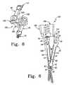
- FIG. 6is a right hand elevation view of the instrument, extensions and anchors of FIG. 4 .
- FIG. 7is a frontal elevation view of the instrument, extensions and anchors of FIG. 4 mounted to a spinal column segment.
- FIG. 8is a top plan view of the guide instrument, extensions and anchors of FIG. 4 with the guide instrument repositioned relative to the anchor extensions.
- FIG. 9is a frontal elevation view of the instrument, extensions and anchors of FIG. 8 mounted to a spinal column segment.
- FIG. 10is a perspective view of an inserter instrument mounted to anchor extensions and a connecting element with the connecting element positioned through receiver portions of the anchors.
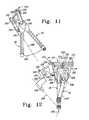
- FIG. 11is an elevation view of another embodiment guide instrument mounted to a pair of anchor extensions.
- FIG. 12is a right hand elevation view of the guide instrument and anchor extensions of FIG. 11 that further includes an alternate position for the guide instrument.
- Instruments and methodsare provided for placement of a secondary anchor in a bony segment in a desired position relative to at least one primary anchor engaged with the bony segment, and to locate at least a portion of the secondary anchor along an alignment axis.
- a connecting elementis positionable between the primary and second anchors and along the alignment axis to connect the primary and secondary anchors to one another.
- the instruments and methodsposition at least a receiver portion of the primary and secondary anchors along the alignment axis prior to positioning the connecting element between the primary and secondary anchors. Accordingly, insertion of the connecting element between the primary and secondary anchors is facilitated since the receiver portions of the primary and second anchors are pre-aligned along the axis in which the connecting element will be positioned.
- the instrumentsinclude a guide instrument mountable to at least one primary anchor and movable relative thereto.
- the guide instrumentincludes a guide member positionable to orient a guide axis at any one of a number of orientations relative to the alignment axis that intersect the alignment axis.
- the guide instrumentcan be employed to guide any one or combination of a drill, a tap, and a secondary anchor to a desired orientation relative to the alignment axis, with a receiving portion of the secondary anchor positioned along the alignment axis.
- a connecting elementis positioned along the alignment axis to a location where it is engageable to the primary and second anchors to stabilize the bony segment.
- the guide instrumentis mounted between first and second anchor extensions extending from first and second primary anchors.
- primary anchoridentifies an anchor engaged to the bony segment prior to placement of the secondary anchor with the guide instrument.
- the alignment axisextends between receiving portions of the primary anchors along the bony segment.
- the guide instrumentincludes an adjustable guide member that defines a guide axis that intersects the alignment axis. When mounted to the anchor extensions of the primary anchors, the guide member can be repositioned to provide a desired trajectory for the secondary anchor into the bony segment. At any position of the guide member, the guide axis intersects the alignment axis.
- drilling and tapping, if necessary, and engagement of the secondary anchor into the bony segmentis controlled so that a receiving portion of the secondary anchor is aligned with the receiving portions of the primary anchors along the alignment axis while the trajectory of the secondary anchor into the bony segment can vary from that of one or both of the primary anchors.
- the secondary anchoris positioned between the primary anchors
- the second anchorcan be positioned to provide an extension of the alignment axis extending between the primary anchors.
- the guide instrumentcan be employed to align receiver portions of two anchors, three anchors, or four or more anchors.
- Guide instrument 100includes a mounting assembly 101 extending along a mounting axis 142 .
- Mounting assembly 101includes a mounting member 102 and a coupling member 150 .
- a mounting pin 130extends between and rotatably couples coupling member 150 to mounting member 102 .
- Mounting member 102is engageable between anchor extensions 40 of a pair of primary anchors, as shown in FIGS. 4-9 .
- a guide member 180is pivotally coupled to coupling member 150 with a hinge pin 170 along a hinge axis 171 .
- Coupling member 150is movable about a rotational center defined by mounting axis 142 to position hinge axis 171 and thus guide member 180 at any one of a number of positions about mounting member 102 .
- Guide member 180defines a guide axis 198 , which can be positioned by pivoting guide member 180 relative to coupling member 150 about hinge axis 171 and/or by rotating coupling member 150 about mounting axis 142 .
- the adjustable positioning provided by coupling member 150 and guide member 180allows a secondary anchor to be positioned into the bony segment at a desired trajectory defined by guide axis 198 .
- Coupling member 150 and guide member 180are structured so that guide axis 198 intersects alignment axis 200 at any position of coupling member 150 and guide member 180 about mounting axis 142 .
- Mounting member 102includes a body 104 comprising opposite first and second sides 106 , 108 and opposite third and fourth sides 110 , 112 .
- a first mounting pin 114extends from first side 106
- a second mounting pin 116extends from second side 108 .
- Body 104further includes a tapered distal end 118 and a proximal end wall 120 .
- a bore 122extends through body 104 and opens at proximal end wall 120 and distal end 118 .
- Third and fourth sides 110 , 112can include a concave surface profile to accommodate passage of drill, tap or driving instruments along mounting member 102 when guide member 180 is positioned so that guide axis 198 is adjacent thereto, as shown in FIGS. 8 and 9 .
- Mounting pins 114 , 116are positionable in receptacles formed in sidewalls 45 adjacent the proximal ends 44 of anchor extensions 40 to mount guide instrument 100 thereto with mounting axis 142 intersecting alignment axis 200 .
- Mounting member 102can be pivoted about mounting pins 114 , 116 , as indicated by arrow 111 in FIG. 7 , to adjust the location of intersection between mounting axis 142 and alignment axis 200 along the bony segment.
- Coupling pin 130extends along mounting axis 142 from a proximal end 133 to a distal end portion 131 .
- Distal end portion 131includes slot 132 extending therealong that opens at a distal end of pin 130 .
- Slot 132separates distal end portion 131 into a first finger 134 and a second finger 136 .
- a first protrusion 138projects radially outwardly from first finger 134
- a second protrusion 140projects radially outwardly from second finger 136 .
- Fingers 134 , 136can deflect toward one another for insertion through bore 122 of mounting member 102 .
- Fingers 134 , 136are resiliently biased to return toward their pre-insertion configuration when projections 138 , 140 extend distally beyond distal end 118 of mounting member 102 .
- Projections 138 , 140engage distal end 118 of mounting member 102 to axially and releasably secure coupling pin 130 to mounting member 102 .
- Coupling member 150includes a body portion 152 and a coupling portion 153 extending laterally from body portion 152 .
- Body portion 152extends from a distal end member 154 to a proximal end wall 156 .
- a bore 158extends through body portion 152 and opens at proximal end wall 156 and at a distal face of distal end member 154 .
- Mounting pin 130is positionable through bore 158 and engageable therein via a press fit, mechanical fastener, welding or other suitable engagement technique.
- Coupling pin 130is rotatable in bore 122 of mounting member 102 so that coupling member 150 can be rotated 360 degrees about mounting member 102 .
- Coupling portion 153include a number of hinge members 160 extending laterally from body portion 152 .
- Hinge members 160form a hinge bore 164 extending therethrough.
- a number of slots 162extend between adjacent hinge members 160 .
- Guide member 180also includes a number of hinge members 190 , which include slots 192 therebetween.
- a hinge bore 194extends through hinge members 190 .
- Guide member 180includes a guide body 182 extending between a distal end member 184 and a proximal end wall 186 .
- a guide passage 188extends along guide axis 198 , and opens at the distal and proximal ends of guide body 182 .
- Hinge members 190extend laterally from guide body 182 such that when guide member 180 is coupled to coupling member 150 , guide axis 198 is offset from the hinge axis 171 defined along hinge member 170 .
- guide axis 198can be universally rotated about mounting axis 142 with coupling member 150 to provide a desired approach to the surgical site relative to anchor extensions 40 and mounting axis 142 .
- coupling member 150can be rotated 360 degrees about mounting axis 142 , allowing hinge axis 171 to be positioned at any location along hinge axis path 173 .
- guide member 180can be positioned to form a linear extension of coupling member 150 , thus providing a maximum angular orientation 202 between mounting axis 142 and guide axis 198 .
- Guide member 180can be pivoted about hinge axis 171 from its linear extension position to a position indicated by guide members 180 ′ or 180 ′′ to provide a minimum angular orientation 204 between guide axes 198 ′, 198 ′′ and mounting axis 142 .
- Guide member 180can further be pivoted to a location between its minimum and maximum angular orientations.
- angular orientations 202 , 204range from about 2 degrees for minimum angular orientation 204 to about 8 degrees for maximum angular orientation 202 .
- Other embodimentscontemplate angular orientations ranging from 0 degrees to about 28 degrees.
- guide axis 198can be oriented relative to alignment axis 200 at any anatomically expected trajectory based on the anatomical location of alignment axis 200 , and also based on the anatomical features for a particular patient.
- Placement of the secondary anchorcan further be guided along mounting axis 142 by removing coupling pin 130 from mounting body 102 .
- drilling, tapping and driving instrumentsare guided through bore 122 to locations intersecting alignment axis 200 .
- the secondary anchorcan also be positioned at an angular orientation of 0 degrees relative to mounting axis 142 .
- guide instrument 100When assembled, as shown in FIGS. 4-7 for example, guide instrument 100 can be mounted to at least one of a pair of anchor extensions 40 with mounting member 102 .
- mounting member 102is positioned between and mounted to each of the pair of anchor extensions 40 .
- Anchor extensions 40are releasably mounted to respective ones of the receiver portions 14 of anchors 10 .
- distal end member 154With guide member 100 mounted to anchor extensions 40 , distal end member 154 extends sufficiently proximally to proximally offset hinge axis 171 from the proximal ends of anchor extensions 40 so that coupling member 150 can be rotated 360 degrees about mounting member 102 .
- Guide member 180can be pivoted about hinge axis 171 in either direction between positions adjacent to body portion 152 of coupling member 150 to a position forming an extension of coupling portion 153 .
- First and second anchor extensions 40extend proximally from respective ones of the primary anchors 10 along a first extension axis 50 and a second extension axis 52 , respectively.
- Anchor extensions 40each include an outer sleeve member 41 extending between a distal portion 42 and a proximal portion 44 .
- Proximal portion 44includes an enlarged, bulbous configuration with flattened medial and lateral sidewalls 45 to facilitate engagement of adjacent anchor extensions 40 to one another.
- the medially oriented walls 45are positioned adjacent the first and second sides 106 , 108 of mounting member 102 , and each includes a receptacle to rotatably receive a corresponding one of the mounting pins 114 , 116 .
- Anchor extensions 40further include a passage 46 extending therethrough and opening proximally and also opening in the receiver portion 14 of anchor 10 .
- Passage 46provides a pathway for placement of a coupling member, such as a set screw, into receiver portions 14 to secure the connecting element to the respective anchor 10 .
- Anchor extensions 40include an inner sleeve member 60 positioned in an outer sleeve member 41 .
- Inner sleeve member 60includes distal fingers 62 projecting distally from distal portion 42 of outer sleeve member 41 .
- Distal fingers 62can include an outer cam surface along which the distal portion 42 of outer sleeve member 41 moves to move distal fingers 62 toward and away from one another.
- Distal fingers 62form a passage 64 therebetween that is alignable with a passage 16 of receiver portion 14 of anchor 10 when coupled thereto.
- Fingers 62can include projections extending therefrom that are positionable in adjacent receptacles formed in the outer surface of receiver portion 14 to firmly secure anchor extension 40 thereto.
- a coupling mechanism 48extends through proximal portion 44 and releasably secures inner and outer sleeve members 60 , 41 in at least first and second positions relative to one another.
- outer sleeve member 41In a first position, shown in FIGS. 4-7 , outer sleeve member 41 is distally advanced so that distal portion 42 extends along distal fingers 62 and biases them toward one another to grip receiver portion 14 of bone anchor 10 therebetween.
- Outer sleeve member 41can also be moved proximally relative to inner sleeve member 60 to allow distal fingers 62 to move away from one another, releasing receiver portion 14 of bone anchor 10 from therebetween.
- Fingers 62can be coupled with a proximally extending body of inner sleeve member 60 via an integral hinge, pins, or other suitable connection means that allows fingers 62 to move toward and away from one another to secure and release anchor 10 therebetween.
- FIGS. 7 , 9 and 10there is shown a bony segment 20 to which anchors 10 are engaged to receive a connecting element 90 .
- bony segment 20includes a first vertebra 22 , a second vertebra 24 , and a third vertebra 26 .
- a first disc space 28is between first and second vertebrae 22 , 24
- a second disc space 30is between second and third vertebrae 24 , 26 .
- Primary anchors 10are engaged to each of the first vertebra 22 and third vertebra 26 using any known insertion technique. It contemplated that receiver portions 14 are multi-axial, and can be pivoted and rotated relative to the engagement portion 12 of the primary and secondary anchors 10 when the engagement portion 12 is engaged to the bony structure. Accordingly receiver portions 14 can be aligned with one another along alignment axis 200 extending between the receiver portions of the primary and secondary anchors 10 . Connecting element 90 is inserted and positioned along alignment axis 200 and through passages 16 of receiver portions 14 . Set screws engaged in receiver portions 14 secure connecting element 90 to the primary anchors 10 , and link primary anchors 10 to another.
- connecting element 90is inserted percutaneously into the patient along an insertion axis that is defined along an extension of alignment axis 200 .
- the connecting element 90is guided into position through passages 16 of receiver portions 14 .
- Other embodimentscontemplate other insertion paths for the connecting element, including top loading and side loading the connecting element for engagement with the anchors, and also placing the anchors through a connecting element already positioned along alignment axis 200 .
- the anchor extensions 40are manipulated through the skin and mounted to mounting member 102 of guide instrument 100 .
- Coupling member 150 and guide member 180are positioned to provide the desired alignment of guide axis 198 for engagement of a secondary anchor 10 to vertebra 24 .
- a holecan be drilled into vertebra 24 and tapped, if necessary, through the guide member 180 along guide axis 198 .
- a self-drilling screwcan be employed and guided into vertebra 24 with guide member 180 .
- guide instrument 100allows placement of the secondary anchor at any one of an infinite number of selectable trajectories into vertebra 24 with receiver portion 14 of secondary anchor 10 positioned along alignment axis 200 .
- guide instrument 220is shown in FIGS. 11 and 12 .
- guide instrument 220is mountable to anchor extensions 40 by clamping the anchor extensions 40 to another adjacent their proximal ends.
- Guide instrument 220includes a mounting assembly 221 that includes a first clamping arm 222 pivotally coupled to a second clamping arm 224 .
- First clamping arm 222includes a distal extension 226 engageable to a laterally oriented sidewall of first anchor extension 40 adjacent a proximal end of anchor extension 40 .
- Second clamping arm 224includes a distal extension 228 engageable to an oppositely facing sidewall of second anchor extension 40 .
- Clamping arms 222 , 224are pivotally coupled to one another at an intermediate joint 230 and pivot thereabout to clamp and release anchor extensions 40 from therebetween.
- a drawbar 234is threadingly received in a passage extending through first clamping arm 222 , and a distal end of draw bar 234 is engaged in second clamping arm 224 .
- Drawbar 234is offset proximally from intermediate joint 230 .
- draw bar 234is threadingly adjusted in first clamping arm 222 with thumb screw 232 in the directions indicated by arrow 250 , its distal end acts on second clamping arm 224 to pivot distal extensions 226 , 228 of clamping arms 222 , 224 toward or away from one another about intermediate joint 230 .
- adjusting drawbar 234 toward second clamping member 224moves distal extensions 226 , 228 toward one another to clamp anchor extensions 40 therebetween.
- Adjusting drawbar 234 away from second clamping member 224moves distal extensions 226 , 228 away from one another to release the anchor extensions 40 positioned therebetween.
- Second clamping member 224includes mounting posts 236 extending laterally therefrom.
- a coupling member 239is rotatably mounted to posts 236 with a mounting pin 238 .
- Coupling member 239is movable by pivoting coupling member 239 relative to mounting assembly 221 in either direction about mounting pin 238 as indicated by arrows 252 .
- Coupling member 239further includes coupling portion 240 opposite mounting pin 238 .
- a hinge pin 242is rotatably received in coupling portion 240 and engaged to guide member 244 .
- Guide member 244is pivotal relative to coupling member 239 with hinge pin 242 as indicated by arrows 254 .
- Guide member 244includes a guide portion 246 forming a guide passage therethrough that extends along guide axis 248 .
- Guide instrument 220is structured so that guide axis 248 intersects alignment axis 200 at any position of guide axis 248 relative to the anchor extensions 40 when guide instrument 200 is mounted to anchors extensions 40 .
- guide axis 248is oriented in the position shown in FIG. 11 , and in the position shown as guide axis 248 ′ in FIG. 12 .
- Coupling member 239 and guide member 244can each be pivoted about their respective pivot axis to the fully extended position, shown in FIG. 12 and indicated therein as guide axis 248 .
- Coupling member 239 and guide member 244can further be pivoted counter-clockwise to locate guide axis on the side of extensions 40 opposite that shown in FIG. 11 . Movement of coupling member 239 and guide member 244 can also locate guide axis 248 at any position between these positions and maintain guide axis 248 in intersection with alignment axis 200 .
- the only limitations in positioning of guide member 244 and coupling member 239are created by the contact of guide member 244 and/or coupling member 239 with one or both of mounting assembly 221 and anchor extensions 240 .
- connecting element 90may be installed and secured to anchors 10 with an inserter instrument such as shown in FIG. 10 and designated generally at 320 .
- Inserter instrument 320includes a configuration adapted for percutaneous placement of connecting element 90 in a two level stabilization procedure. Suitable inserter instruments and anchor extensions are also discussed in U.S. Pat. No. 6,530,929, which is incorporated herein by reference in its entirety.
- a third anchor extension 40is positioned through the path formed during placement of secondary anchor 10 and mounted to receiver portion 14 of secondary anchor 10 .
- the third anchor extension 40is manipulated through the skin and tissue of the patient and positioned between and coupled to the anchor extensions 40 extending from the primary anchors 10 . Coupling of the proximal portions 44 to one another aligns the passages 16 of the multi-axial receiver portions 14 along alignment axis 200 .
- Inserter instrument 320includes a distal portion 324 transversely oriented to and extending from arms 322 .
- Distal portion 324includes an arm 331 curved along a radius that extends from the pivotal connection point of arms 322 with anchor extensions 40 to alignment axis 200 .
- Connecting element 90is coupled to and extends from arm 331 adjacent a proximal connecting end 91 of connecting element 90 , and has a sufficient length extending to a distal insertion end 92 for a two-level stabilization procedure.
- Connecting element 90can be curved with a radius of curvature equal to the distance between passageways 16 of anchors 10 and a pivot axis of inserter instrument 320 about anchor extensions 40 .
- Connecting element 90is fixed on inserter 324 and readied for percutaneous insertion into passageways 16 of anchors 10 .
- Inserter instrument 320swings about the pivot axis to move connecting element 90 toward receiver portions 14 along an extension of alignment axis 200 , and thereby introducing leading end of connecting element 90 into the subject's body towards the aligned passages 16 of anchors 10 .
- Connecting element 90 and inserter instrument 320are further pivoted to pass portions of connecting element 90 through passages 16 of anchors 10 and finally position connecting element along alignment axis 200 and within receiver portions 14 .
- Connecting element 90is placed through passages 16 of anchors 10 to a desired position, which can be confirmed radiographically or with any known imaging technique.
- Set screws associated with each anchor 10can be driven downwardly through passages 46 of anchor extensions 40 to contact connecting element 90 and seat it in receiver portions 14 of anchors 10 .
- Arm 331can then be uncoupled from connecting element 90 and removed from the patient by swinging inserter instrument 320 back along path in which it was inserted. Inserter 324 is removed from anchor extensions 40 , and anchor extensions 40 are uncoupled from one another. Anchor extensions 40 are then removed from the patient.
- connecting element 90is installed to stabilize a three vertebrae 22 , 24 , 26 after placement of one or more implants into one or more of the disc spaces 28 , 30 .
- the methodcan include removing intervertebral disc material from the space between vertebral bodies and/or introducing an implant into the disc space.
- Implantcan be one or more interbody fusion devices, support members, artificial disc devices, annulus repair devices, and/or artificial ligaments.
- the anchor extensions 40can be manipulated by the surgeon to apply a load to compress or distract the vertebrae prior to engaging connecting element 90 to anchors 10 . In some surgical procedures, it may be desirable to insert one or more additional connecting elements for stabilization along the same vertebral levels, or along different vertebral levels.
- Connecting element 90can be an elongated rod or shaft curved along its length between connecting end 91 and insertion end 92 .
- connecting element 90can include any configuration known for a rod, plate, implant, or fastener, so long as connecting element 90 is engageable to the bony segment.
- connecting element 90can be elastic or super-elastic member in the form of a cable, band or artificial ligament that used in tethering or other surgical procedures.
- Connecting element 90can be percutaneously or non-percutaneously inserted with an inserter instrument, or with a freehand technique.
- a suitable anchor 10is a multi-axial screw such as described in U.S. Pat. Nos. 5,797,911 and 5,879,350, each of which is incorporated herein by reference.
- Other examples for anchors 10include uni-axial screws, bolts, clamps, hooks, and pins, for example. It is further contemplated that one or more of the anchors can include a multi-axial head and one or more of the other anchors include an uni-axial head.
- the anchorscan be cannulated to facilitate placement over a guidewire and into the vertebra in minimally invasive procedures, or can be non-cannulated. Cannulated anchors can further include one or more fenestrations or openings for placement of bone cement or other material therethrough.
- Pre-operative planning and image guided navigation of anchor placement and installation of connecting element 90are also contemplated.
- the surgical techniquescan employ any type of known imaging system to determine and locate optimum placement and orientation of the anchors in the bony structure and, if necessary, to locate skin locations for percutaneous puncture entry of the anchors and connecting element.
- Primary anchor insertioncan be monitored using any known viewing instrument or apparatus, and performed under any known surgical technique.
- primary anchors 10can be placed through a cannula or sleeve inserted through the skin that forms a working channel to the anchor location over the target bone.
- Anchor placement into the bony structurecan be monitored endoscopically, microscopically, fluoroscopically, radiographically and/or with naked eye visualization through the cannula.
- Primary anchor placementcan also be performed through micro-incisions, or through open incisions in which the skin and tissue is retracted to expose the bony structure.
- a guidewire of sufficient lengthis inserted percutaneously and anchored to the bony structure, such as a pedicle of the vertebra.
- the guidewireis coupled to a trackable instrument that is tracked via an image guided surgical system that generates a display on a computer monitor.
- various instruments for preparing and inserting the screw into the bony structurecan be guided by the guidewire.
- the preparation and insertioncan be monitored via a tracking instrument coupled to the various preparation and insertion instruments.
- a guide instrumentis mounted to the anchor extensions to guide placement of the secondary anchor at a desired trajectory into the pedicle located between the pedicles engaged by the primary anchors.
- Connecting elementscan be engaged on both sides of midline M of the spine, and along one or more levels of the spine.
- the connecting elementcan be engaged to stabilize adjacent vertebra in conjunction with any minimally invasive or open surgical techniques for placement of one or more implants into a disc space.
- one or more interbody fusion devices or intervertebral spacersmay be inserted into the disc space via an anterior, anterior oblique, lateral, postero-lateral, or transforaminal approach, and connecting element 90 can be positioned and engaged to the spinal column segment from a posterior approach.
- connecting element 90can be used to stabilize adjacent vertebrae, or any other bony structure, without placement of implants between structures comprising bony segment 20 .
Landscapes
- Health & Medical Sciences (AREA)
- Surgery (AREA)
- Life Sciences & Earth Sciences (AREA)
- Orthopedic Medicine & Surgery (AREA)
- Heart & Thoracic Surgery (AREA)
- Veterinary Medicine (AREA)
- Engineering & Computer Science (AREA)
- Biomedical Technology (AREA)
- Nuclear Medicine, Radiotherapy & Molecular Imaging (AREA)
- Medical Informatics (AREA)
- Molecular Biology (AREA)
- Animal Behavior & Ethology (AREA)
- General Health & Medical Sciences (AREA)
- Public Health (AREA)
- Neurology (AREA)
- Dentistry (AREA)
- Oral & Maxillofacial Surgery (AREA)
- Surgical Instruments (AREA)
- Prostheses (AREA)
Abstract
Description
Claims (38)
Priority Applications (9)
| Application Number | Priority Date | Filing Date | Title |
|---|---|---|---|
| US10/674,036US7455685B2 (en) | 2003-09-29 | 2003-09-29 | Instruments and methods for securing a connecting element along a bony segment |
| PCT/US2004/031093WO2005032383A1 (en) | 2003-09-29 | 2004-09-22 | Guide to align bone anchors |
| AU2004277926AAU2004277926A1 (en) | 2003-09-29 | 2004-09-22 | Guide to align bone anchors |
| EP04784801AEP1680031A1 (en) | 2003-09-29 | 2004-09-22 | Guide to align bone anchors |
| CA002540164ACA2540164A1 (en) | 2003-09-29 | 2004-09-22 | Guide to align bone anchors |
| JP2006528141AJP4646916B2 (en) | 2003-09-29 | 2004-09-22 | Guide for aligning bone anchors |
| KR1020067008146AKR20060117922A (en) | 2003-09-29 | 2004-09-22 | Apparatus and method for securing connective elements along bone segments |
| CNA2004800280666ACN1859875A (en) | 2003-09-29 | 2004-09-22 | Instruments and methods for securing a connecting element along a bony segment |
| US12/274,207US7976569B2 (en) | 2003-09-29 | 2008-11-19 | Instruments and methods for securing connecting elements along a bony segment |
Applications Claiming Priority (1)
| Application Number | Priority Date | Filing Date | Title |
|---|---|---|---|
| US10/674,036US7455685B2 (en) | 2003-09-29 | 2003-09-29 | Instruments and methods for securing a connecting element along a bony segment |
Related Child Applications (1)
| Application Number | Title | Priority Date | Filing Date |
|---|---|---|---|
| US12/274,207DivisionUS7976569B2 (en) | 2003-09-29 | 2008-11-19 | Instruments and methods for securing connecting elements along a bony segment |
Publications (2)
| Publication Number | Publication Date |
|---|---|
| US20050070917A1 US20050070917A1 (en) | 2005-03-31 |
| US7455685B2true US7455685B2 (en) | 2008-11-25 |
Family
ID=34376778
Family Applications (2)
| Application Number | Title | Priority Date | Filing Date |
|---|---|---|---|
| US10/674,036Expired - LifetimeUS7455685B2 (en) | 2003-09-29 | 2003-09-29 | Instruments and methods for securing a connecting element along a bony segment |
| US12/274,207Expired - Fee RelatedUS7976569B2 (en) | 2003-09-29 | 2008-11-19 | Instruments and methods for securing connecting elements along a bony segment |
Family Applications After (1)
| Application Number | Title | Priority Date | Filing Date |
|---|---|---|---|
| US12/274,207Expired - Fee RelatedUS7976569B2 (en) | 2003-09-29 | 2008-11-19 | Instruments and methods for securing connecting elements along a bony segment |
Country Status (8)
| Country | Link |
|---|---|
| US (2) | US7455685B2 (en) |
| EP (1) | EP1680031A1 (en) |
| JP (1) | JP4646916B2 (en) |
| KR (1) | KR20060117922A (en) |
| CN (1) | CN1859875A (en) |
| AU (1) | AU2004277926A1 (en) |
| CA (1) | CA2540164A1 (en) |
| WO (1) | WO2005032383A1 (en) |
Cited By (54)
| Publication number | Priority date | Publication date | Assignee | Title |
|---|---|---|---|---|
| US20050021031A1 (en)* | 1999-10-20 | 2005-01-27 | Foley Kevin T. | Instruments and methods for stabilization of bony structures |
| US20080119845A1 (en)* | 2006-09-25 | 2008-05-22 | Archus Orthopedics, Inc. | Facet replacement device removal and revision systems and methods |
| US20080249568A1 (en)* | 2004-10-25 | 2008-10-09 | Kuiper Mark K | Crossbar Spinal Prosthesis Having a Modular Design and Systems for Treating Spinal Pathologies |
| US20100049206A1 (en)* | 2008-06-13 | 2010-02-25 | The University Of Toledo | Insertion assembly for minimally invasive spinal surgery |
| US20100106250A1 (en)* | 2004-08-23 | 2010-04-29 | Abdou M Samy | Bone fixation and fusion device |
| US20100114174A1 (en)* | 2008-10-30 | 2010-05-06 | Bryan Jones | Systems and Methods for Delivering Bone Cement to a Bone Anchor |
| DE202010005202U1 (en) | 2010-04-14 | 2010-06-17 | Aesculap Ag | Orthopedic fixation system and target device for such a fixation system |
| US7914556B2 (en) | 2005-03-02 | 2011-03-29 | Gmedelaware 2 Llc | Arthroplasty revision system and method |
| US7951175B2 (en) | 2005-03-04 | 2011-05-31 | Depuy Spine, Inc. | Instruments and methods for manipulating a vertebra |
| US7951172B2 (en) | 2005-03-04 | 2011-05-31 | Depuy Spine Sarl | Constrained motion bone screw assembly |
| US7951174B2 (en) | 2005-10-21 | 2011-05-31 | Depuy Spine, Inc. | Adjustable bone screw assembly |
| US20110184519A1 (en)* | 2010-01-26 | 2011-07-28 | Warsaw Orthopedic, Inc. | Sacro-iliac joint implant system, method and instrument |
| US20110218581A1 (en)* | 2010-03-02 | 2011-09-08 | Warsaw Orthopedic, Inc. | Systems and methods for minimally invasive surgical procedures |
| WO2011128220A1 (en) | 2010-04-14 | 2011-10-20 | Aesculap Ag | Orthopedic fixation system and targeting device for such a fixation system |
| US8066740B2 (en) | 1999-10-22 | 2011-11-29 | Gmedelaware 2 Llc | Facet joint prostheses |
| US8172855B2 (en)* | 2004-11-24 | 2012-05-08 | Abdou M S | Devices and methods for inter-vertebral orthopedic device placement |
| US8187303B2 (en) | 2004-04-22 | 2012-05-29 | Gmedelaware 2 Llc | Anti-rotation fixation element for spinal prostheses |
| US8206394B2 (en) | 2009-05-13 | 2012-06-26 | Depuy Spine, Inc. | Torque limited instrument for manipulating a spinal rod relative to a bone anchor |
| US8292896B2 (en) | 2004-10-05 | 2012-10-23 | Abdou M Samy | Devices and methods for inter-vertebral orthopedic device placement |
| US8303630B2 (en) | 2006-07-27 | 2012-11-06 | Samy Abdou | Devices and methods for the minimally invasive treatment of spinal stenosis |
| US8348952B2 (en) | 2006-01-26 | 2013-01-08 | Depuy International Ltd. | System and method for cooling a spinal correction device comprising a shape memory material for corrective spinal surgery |
| US8398681B2 (en) | 2004-08-18 | 2013-03-19 | Gmedelaware 2 Llc | Adjacent level facet arthroplasty devices, spine stabilization systems, and methods |
| US8414614B2 (en) | 2005-10-22 | 2013-04-09 | Depuy International Ltd | Implant kit for supporting a spinal column |
| US8425563B2 (en) | 2006-01-13 | 2013-04-23 | Depuy International Ltd. | Spinal rod support kit |
| US8430914B2 (en) | 2007-10-24 | 2013-04-30 | Depuy Spine, Inc. | Assembly for orthopaedic surgery |
| US8496686B2 (en) | 2005-03-22 | 2013-07-30 | Gmedelaware 2 Llc | Minimally invasive spine restoration systems, devices, methods and kits |
| US8608746B2 (en) | 2008-03-10 | 2013-12-17 | DePuy Synthes Products, LLC | Derotation instrument with reduction functionality |
| US8675930B2 (en) | 2004-04-22 | 2014-03-18 | Gmedelaware 2 Llc | Implantable orthopedic device component selection instrument and methods |
| US8702755B2 (en) | 2006-08-11 | 2014-04-22 | Gmedelaware 2 Llc | Angled washer polyaxial connection for dynamic spine prosthesis |
| US8709015B2 (en) | 2008-03-10 | 2014-04-29 | DePuy Synthes Products, LLC | Bilateral vertebral body derotation system |
| US8795335B1 (en) | 2009-11-06 | 2014-08-05 | Samy Abdou | Spinal fixation devices and methods of use |
| US8870920B2 (en) | 2005-10-07 | 2014-10-28 | M. Samy Abdou | Devices and methods for inter-vertebral orthopedic device placement |
| US9056016B2 (en) | 2003-12-15 | 2015-06-16 | Gmedelaware 2 Llc | Polyaxial adjustment of facet joint prostheses |
| US9101416B2 (en) | 2003-01-24 | 2015-08-11 | DePuy Synthes Products, Inc. | Spinal rod approximator |
| US9155580B2 (en) | 2011-08-25 | 2015-10-13 | Medos International Sarl | Multi-threaded cannulated bone anchors |
| US9198766B2 (en) | 2003-05-14 | 2015-12-01 | Gmedelaware 2 Llc | Prostheses, tools, and methods for replacement of natural facet joints with artificial facet joint surfaces |
| US9314274B2 (en) | 2011-05-27 | 2016-04-19 | DePuy Synthes Products, Inc. | Minimally invasive spinal fixation system including vertebral alignment features |
| US9358122B2 (en) | 2011-01-07 | 2016-06-07 | K2M, Inc. | Interbody spacer |
| US9402663B2 (en) | 2010-04-23 | 2016-08-02 | DePuy Synthes Products, Inc. | Minimally invasive instrument set, devices and related methods |
| US9498262B2 (en) | 2006-04-11 | 2016-11-22 | DePuy Synthes Products, Inc. | Minimally invasive fixation system |
| US20160361074A1 (en)* | 2015-06-09 | 2016-12-15 | Warsaw Orthopedic, Inc. | Surgical instrument and method |
| US9808281B2 (en) | 2009-05-20 | 2017-11-07 | DePuy Synthes Products, Inc. | Patient-mounted retraction |
| US10543107B2 (en) | 2009-12-07 | 2020-01-28 | Samy Abdou | Devices and methods for minimally invasive spinal stabilization and instrumentation |
| US10548740B1 (en) | 2016-10-25 | 2020-02-04 | Samy Abdou | Devices and methods for vertebral bone realignment |
| US10575961B1 (en) | 2011-09-23 | 2020-03-03 | Samy Abdou | Spinal fixation devices and methods of use |
| US10695105B2 (en) | 2012-08-28 | 2020-06-30 | Samy Abdou | Spinal fixation devices and methods of use |
| WO2020197830A1 (en)* | 2019-03-22 | 2020-10-01 | Texas Scottish Rite Hospital For Children | Hinge-link spinal correction device and method |
| US10857003B1 (en) | 2015-10-14 | 2020-12-08 | Samy Abdou | Devices and methods for vertebral stabilization |
| US10973556B2 (en) | 2008-06-17 | 2021-04-13 | DePuy Synthes Products, Inc. | Adjustable implant assembly |
| US10973648B1 (en) | 2016-10-25 | 2021-04-13 | Samy Abdou | Devices and methods for vertebral bone realignment |
| US11006982B2 (en) | 2012-02-22 | 2021-05-18 | Samy Abdou | Spinous process fixation devices and methods of use |
| US11173040B2 (en) | 2012-10-22 | 2021-11-16 | Cogent Spine, LLC | Devices and methods for spinal stabilization and instrumentation |
| US11179248B2 (en) | 2018-10-02 | 2021-11-23 | Samy Abdou | Devices and methods for spinal implantation |
| US12440248B2 (en) | 2022-06-28 | 2025-10-14 | DePuy Synthes Products, Inc. | Minimally invasive instrument set, devices, and related methods |
Families Citing this family (57)
| Publication number | Priority date | Publication date | Assignee | Title |
|---|---|---|---|---|
| US8002798B2 (en) | 2003-09-24 | 2011-08-23 | Stryker Spine | System and method for spinal implant placement |
| US7955355B2 (en) | 2003-09-24 | 2011-06-07 | Stryker Spine | Methods and devices for improving percutaneous access in minimally invasive surgeries |
| US7967826B2 (en)* | 2003-10-21 | 2011-06-28 | Theken Spine, Llc | Connector transfer tool for internal structure stabilization systems |
| US7588575B2 (en) | 2003-10-21 | 2009-09-15 | Innovative Spinal Technologies | Extension for use with stabilization systems for internal structures |
| US7588588B2 (en) | 2003-10-21 | 2009-09-15 | Innovative Spinal Technologies | System and method for stabilizing of internal structures |
| US7776051B2 (en)* | 2004-05-03 | 2010-08-17 | Theken Spine, Llc | System and method for displacement of bony structures |
| US7651496B2 (en)* | 2004-07-23 | 2010-01-26 | Zimmer Spine, Inc. | Methods and apparatuses for percutaneous implant delivery |
| US20070239159A1 (en)* | 2005-07-22 | 2007-10-11 | Vertiflex, Inc. | Systems and methods for stabilization of bone structures |
| US8162985B2 (en)* | 2004-10-20 | 2012-04-24 | The Board Of Trustees Of The Leland Stanford Junior University | Systems and methods for posterior dynamic stabilization of the spine |
| US8226690B2 (en) | 2005-07-22 | 2012-07-24 | The Board Of Trustees Of The Leland Stanford Junior University | Systems and methods for stabilization of bone structures |
| US8025680B2 (en)* | 2004-10-20 | 2011-09-27 | Exactech, Inc. | Systems and methods for posterior dynamic stabilization of the spine |
| US7935134B2 (en) | 2004-10-20 | 2011-05-03 | Exactech, Inc. | Systems and methods for stabilization of bone structures |
| US8267969B2 (en)* | 2004-10-20 | 2012-09-18 | Exactech, Inc. | Screw systems and methods for use in stabilization of bone structures |
| US7569061B2 (en) | 2004-11-16 | 2009-08-04 | Innovative Spinal Technologies, Inc. | Off-axis anchor guidance system |
| US20110190822A1 (en)* | 2004-11-16 | 2011-08-04 | James Spitler | Internal Structure Stabilization System for Spanning Three or More Structures |
| US7727260B2 (en)* | 2005-03-24 | 2010-06-01 | Accelerated Innovation, Llc | Method and apparatus for bone stabilization |
| US8177817B2 (en) | 2005-05-18 | 2012-05-15 | Stryker Spine | System and method for orthopedic implant configuration |
| US7749232B2 (en)* | 2005-05-24 | 2010-07-06 | Anthony Salerni | Electromagnetically guided spinal rod system and related methods |
| US8523865B2 (en) | 2005-07-22 | 2013-09-03 | Exactech, Inc. | Tissue splitter |
| US7695475B2 (en)* | 2005-08-26 | 2010-04-13 | Warsaw Orthopedic, Inc. | Instruments for minimally invasive stabilization of bony structures |
| US20070100350A1 (en)* | 2005-10-31 | 2007-05-03 | Deffenbaugh Daren L | Suture anchor cartridge holder, suture anchor cartridge and associated method |
| US20070100351A1 (en)* | 2005-10-31 | 2007-05-03 | Deffenbaugh Daren L | Multiple suture anchor delivery device, suture anchor delivery kit and associated method |
| EP1981422B1 (en) | 2006-02-06 | 2018-10-24 | Stryker European Holdings I, LLC | Rod contouring apparatus for percutaneous pedicle screw extension |
| US20080015601A1 (en)* | 2006-06-14 | 2008-01-17 | Michael Castro | Reduction device and method of use |
| US8157809B2 (en)* | 2006-09-25 | 2012-04-17 | Stryker Spine | Percutaneous compression and distraction system |
| DE602007008112D1 (en)* | 2006-09-25 | 2010-09-09 | Stryker Spine | ALIGNMENT CONNECTION FOR BAR CONTOURING |
| US7686809B2 (en) | 2006-09-25 | 2010-03-30 | Stryker Spine | Rod inserter and rod with reduced diameter end |
| EP2073734A1 (en)* | 2006-09-25 | 2009-07-01 | Stryker Spine | Force limiting persuader-reducer |
| US8162952B2 (en) | 2006-09-26 | 2012-04-24 | Ebi, Llc | Percutaneous instrument assembly |
| US8038699B2 (en) | 2006-09-26 | 2011-10-18 | Ebi, Llc | Percutaneous instrument assembly |
| US8096996B2 (en) | 2007-03-20 | 2012-01-17 | Exactech, Inc. | Rod reducer |
| US20080119862A1 (en)* | 2006-11-21 | 2008-05-22 | Wicker Meleah Ann | Surgical Instrument for Supplying a Counter-Torque When Securing a Spinal Prosthesis |
| US8734452B2 (en)* | 2006-12-15 | 2014-05-27 | Spinefrontier, Inc | Guidance system,tools and devices for spinal fixation |
| US7981115B2 (en)* | 2007-04-11 | 2011-07-19 | Warsaw Orthopedic, Inc. | Instruments and methods for sizing a connecting element for positioning along a bony segment |
| US20080269805A1 (en) | 2007-04-25 | 2008-10-30 | Warsaw Orthopedic, Inc. | Methods for correcting spinal deformities |
| US20090082811A1 (en)* | 2007-09-26 | 2009-03-26 | Depuy Spine, Inc. | Devices and methods for positioning a spinal fixation element |
| US20090088803A1 (en)* | 2007-10-01 | 2009-04-02 | Warsaw Orthopedic, Inc. | Flexible members for correcting spinal deformities |
| US8105362B2 (en)* | 2008-06-30 | 2012-01-31 | Duarte Luis E | Percutaneous spinal rod insertion system and related methods |
| US9655658B2 (en) | 2009-10-14 | 2017-05-23 | Ebi, Llc | Deformable device for minimally invasive fixation |
| US8540719B2 (en) | 2010-02-09 | 2013-09-24 | Aesculap Implant Systems, Llc | Percutaneous rod insertion system and method |
| US8623022B2 (en) | 2010-09-20 | 2014-01-07 | Zimmer Spine, Inc. | Surgical instrument support system and method |
| US8721566B2 (en)* | 2010-11-12 | 2014-05-13 | Robert A. Connor | Spinal motion measurement device |
| US8585705B2 (en)* | 2011-10-18 | 2013-11-19 | Intelligent Implant Systems, Llc | Percutaneous instrumentation and surgical procedure |
| US20130110174A1 (en)* | 2011-10-31 | 2013-05-02 | Warsaw Orthopedic, Inc. | Methods for installing a vertebral construct |
| US9125703B2 (en) | 2012-01-16 | 2015-09-08 | K2M, Inc. | Rod reducer, compressor, distractor system |
| US9827020B2 (en) | 2013-03-14 | 2017-11-28 | Stryker European Holdings I, Llc | Percutaneous spinal cross link system and method |
| CA2846149C (en) | 2013-03-14 | 2018-03-20 | Stryker Spine | Systems and methods for percutaneous spinal fusion |
| US10117666B2 (en) | 2013-09-26 | 2018-11-06 | Misonix Inc. | Ultrasonic instrument and method using same |
| US9744050B1 (en) | 2013-12-06 | 2017-08-29 | Stryker European Holdings I, Llc | Compression and distraction system for percutaneous posterior spinal fusion |
| US9408716B1 (en) | 2013-12-06 | 2016-08-09 | Stryker European Holdings I, Llc | Percutaneous posterior spinal fusion implant construction and method |
| US10159579B1 (en) | 2013-12-06 | 2018-12-25 | Stryker European Holdings I, Llc | Tubular instruments for percutaneous posterior spinal fusion systems and methods |
| CA2874390C (en) | 2013-12-13 | 2018-03-06 | Stryker European Holdings I, Llc | Tissue retraction and vertebral displacement devices, systems, and methods for posterior spinal fusion |
| EP2886074B1 (en)* | 2013-12-20 | 2016-09-14 | Biedermann Technologies GmbH & Co. KG | Rod insertion device |
| CA3008161C (en) | 2014-12-09 | 2023-09-26 | John A. Heflin | Spine alignment system |
| CN109171923A (en)* | 2015-07-24 | 2019-01-11 | 镱钛科技股份有限公司 | parallel corrector |
| CN105496477A (en)* | 2016-01-16 | 2016-04-20 | 刘静 | Surgical operating instrument connecting piece |
| EP4529868A3 (en)* | 2017-10-06 | 2025-09-17 | MED-EL Elektromedizinische Geräte GmbH | Drilling platform tool for surgeries |
Citations (55)
| Publication number | Priority date | Publication date | Assignee | Title |
|---|---|---|---|---|
| US2338159A (en) | 1941-03-03 | 1944-01-04 | Henry W Appleton | Needle threader |
| US3299883A (en)* | 1963-11-08 | 1967-01-24 | Engelhard Hanovia Inc | Gynecologic instrument |
| SU839513A1 (en) | 1979-09-14 | 1981-06-23 | Центральный Ордена Трудовогокрасного Знамени Научно-Исследова-Тельский Институт Травматологии Иортопедии Им. H.H.Приорова | Device for guiding wires |
| US4335715A (en) | 1980-06-20 | 1982-06-22 | Kirkley William H | Osteotomy guide |
| US4545374A (en) | 1982-09-03 | 1985-10-08 | Jacobson Robert E | Method and instruments for performing a percutaneous lumbar diskectomy |
| US4570624A (en) | 1983-08-10 | 1986-02-18 | Henry Ford Hospital | Universal guide for inserting parallel pins |
| US4573448A (en) | 1983-10-05 | 1986-03-04 | Pilling Co. | Method for decompressing herniated intervertebral discs |
| US4722331A (en) | 1985-09-03 | 1988-02-02 | Fox James M | Orthopaedic tool guide |
| US4883048A (en) | 1986-10-03 | 1989-11-28 | Purnell Mark L | Apparatus and method for use in performing a surgical operation |
| US4896661A (en) | 1988-02-05 | 1990-01-30 | Pfizer, Inc. | Multi purpose orthopedic ratcheting forceps |
| US4955885A (en) | 1988-12-21 | 1990-09-11 | Zimmer, Inc. | Surgical slider instrument and method of using instrument |
| US5067954A (en)* | 1988-07-25 | 1991-11-26 | Ilizarov Gavriil A | Distraction apparatus for plastic reconstruction of hand |
| US5163940A (en) | 1991-03-04 | 1992-11-17 | American Cyanamid Company | Surgical drill guide for tibia |
| US5242443A (en) | 1991-08-15 | 1993-09-07 | Smith & Nephew Dyonics, Inc. | Percutaneous fixation of vertebrae |
| US5242444A (en) | 1991-11-04 | 1993-09-07 | University Of Florida | Lumbosacral fixation and fusion method and device |
| US5281223A (en) | 1992-09-21 | 1994-01-25 | Ray R Charles | Tool and method for derotating scoliotic spine |
| JPH06105852A (en) | 1992-09-28 | 1994-04-19 | Nagano Keiki Seisakusho Ltd | Template apparatus for screw pin-fixing operation |
| US5334205A (en) | 1993-06-30 | 1994-08-02 | The United States Of America As Represented By The Secretary Of The Air Force | Sacroiliac joint fixation guide |
| US5383454A (en) | 1990-10-19 | 1995-01-24 | St. Louis University | System for indicating the position of a surgical probe within a head on an image of the head |
| US5437667A (en) | 1992-11-10 | 1995-08-01 | Innovative Orthopaedics, Manufacturing, Inc. | Dynamic external fixator for the wrist |
| US5569248A (en) | 1992-03-17 | 1996-10-29 | Danek Medical, Inc. | Apparatus for subcutaneous suprafascial pedicular internal fixation |
| US5591167A (en) | 1994-02-15 | 1997-01-07 | Sofamor, S.N.C. | Anterior dorso-lumbar spinal osteosynthesis instrumentation for the correction of kyphosis |
| US5591165A (en) | 1992-11-09 | 1997-01-07 | Sofamor, S.N.C. | Apparatus and method for spinal fixation and correction of spinal deformities |
| US5601562A (en) | 1995-02-14 | 1997-02-11 | Arthrex, Inc. | Forked insertion tool and metnod of arthroscopic surgery using the same |
| US5613971A (en) | 1995-08-11 | 1997-03-25 | Depuy Inc. | Ratcheting tibial and femoral guide |
| US5643273A (en) | 1995-02-17 | 1997-07-01 | Clark; Ron | ACL bone tunnel projection drill guide and method for its use |
| WO1997030666A2 (en) | 1996-02-22 | 1997-08-28 | Sdgi Holdings, Inc. | Methods and instruments for interbody fusion |
| WO1997038639A1 (en) | 1996-04-18 | 1997-10-23 | Tresona Instrument Ab | Device and method for correcting and stabilising a deviating curvature of a spinal column |
| US5681320A (en) | 1991-12-13 | 1997-10-28 | Mcguire; David A. | Bone-cutting guide |
| US5704937A (en) | 1993-08-27 | 1998-01-06 | Paulette Fairant | Operative equipment for fixing spinal instrumentation |
| US5720751A (en) | 1996-11-27 | 1998-02-24 | Jackson; Roger P. | Tools for use in seating spinal rods in open ended implants |
| US5725532A (en) | 1996-09-10 | 1998-03-10 | Shoemaker; Steven | Integrated surgical reduction clamp and drill guide |
| US5735857A (en) | 1996-07-22 | 1998-04-07 | Bristol-Myers Squibb Co. | Prosthetic gripping instrument |
| US5741266A (en) | 1996-09-19 | 1998-04-21 | Biomet, Inc. | Pin placement guide and method of making a bone entry hole for implantation of an intramedullary nail |
| US5752962A (en) | 1993-11-15 | 1998-05-19 | D'urso; Paul S. | Surgical procedures |
| US5772594A (en) | 1995-10-17 | 1998-06-30 | Barrick; Earl F. | Fluoroscopic image guided orthopaedic surgery system with intraoperative registration |
| EP0858780A2 (en) | 1997-02-13 | 1998-08-19 | ORTHOFIX S.r.l. | Orthopaedic apparatus, particularly for the surgical correction of bone deformations |
| USD401335S (en)* | 1997-07-28 | 1998-11-17 | Tibor Koros | Combined cervical and lumbar extractor and injector surgical instrument |
| DE19726754A1 (en) | 1997-06-24 | 1999-02-04 | Aesculap Ag & Co Kg | Implant for fixing parts of bones in particular at spine |
| US5871445A (en) | 1993-04-26 | 1999-02-16 | St. Louis University | System for indicating the position of a surgical probe within a head on an image of the head |
| WO1999015097A2 (en) | 1997-09-24 | 1999-04-01 | Surgical Navigation Technologies, Inc. | Percutaneous registration apparatus and method for use in computer-assisted surgical navigation |
| US5891158A (en) | 1997-10-23 | 1999-04-06 | Manwaring; Kim H. | Method and system for directing an instrument to a target |
| US5891150A (en) | 1996-12-04 | 1999-04-06 | Chan; Kwan-Ho | Apparatus and method for fixing a ligament in a bone tunnel |
| WO1999026549A1 (en) | 1997-11-20 | 1999-06-03 | Surgical Navigation Technologies, Inc. | An image guided awl/tap/screwdriver |
| US5910141A (en) | 1997-02-12 | 1999-06-08 | Sdgi Holdings, Inc. | Rod introduction apparatus |
| US6036692A (en) | 1997-02-12 | 2000-03-14 | Sdgi Holdings, Inc. | Rod introducer forceps |
| WO2000044288A1 (en) | 1999-01-30 | 2000-08-03 | Aesculap Ag & Co. Kg | Surgical instrument for inserting intervertebral implants |
| US6099528A (en) | 1997-05-29 | 2000-08-08 | Sofamor S.N.C. | Vertebral rod for spinal osteosynthesis instrumentation and osteosynthesis instrumentation, including said rod |
| US6123707A (en) | 1999-01-13 | 2000-09-26 | Spinal Concepts, Inc. | Reduction instrument |
| US6235028B1 (en) | 2000-02-14 | 2001-05-22 | Sdgi Holdings, Inc. | Surgical guide rod |
| US20020161368A1 (en)* | 1999-10-20 | 2002-10-31 | Foley Kevin T. | Instruments and methods for stabilization of bony structures |
| US20050038432A1 (en)* | 2003-04-25 | 2005-02-17 | Shaolian Samuel M. | Articulating spinal fixation rod and system |
| US20050234449A1 (en)* | 2002-07-10 | 2005-10-20 | Joseph Aferzon | Spinal support coupling device |
| US20060149238A1 (en)* | 2005-01-04 | 2006-07-06 | Sherman Michael C | Systems and methods for spinal stabilization with flexible elements |
| US7118576B2 (en)* | 2002-05-15 | 2006-10-10 | Nevmet Corporation | Multiportal device with linked cannulae and method for percutaneous surgery |
Family Cites Families (3)
| Publication number | Priority date | Publication date | Assignee | Title |
|---|---|---|---|---|
| US5797911A (en) | 1996-09-24 | 1998-08-25 | Sdgi Holdings, Inc. | Multi-axial bone screw assembly |
| US5879350A (en)* | 1996-09-24 | 1999-03-09 | Sdgi Holdings, Inc. | Multi-axial bone screw assembly |
| AU2003287273C1 (en)* | 2002-10-30 | 2010-01-07 | Zimmer Spine, Inc. | Spinal stabilization system insertion and methods |
- 2003
- 2003-09-29USUS10/674,036patent/US7455685B2/ennot_activeExpired - Lifetime
- 2004
- 2004-09-22EPEP04784801Apatent/EP1680031A1/ennot_activeWithdrawn
- 2004-09-22CNCNA2004800280666Apatent/CN1859875A/enactivePending
- 2004-09-22WOPCT/US2004/031093patent/WO2005032383A1/enactiveSearch and Examination
- 2004-09-22CACA002540164Apatent/CA2540164A1/ennot_activeAbandoned
- 2004-09-22KRKR1020067008146Apatent/KR20060117922A/ennot_activeWithdrawn
- 2004-09-22AUAU2004277926Apatent/AU2004277926A1/ennot_activeAbandoned
- 2004-09-22JPJP2006528141Apatent/JP4646916B2/ennot_activeExpired - Fee Related
- 2008
- 2008-11-19USUS12/274,207patent/US7976569B2/ennot_activeExpired - Fee Related
Patent Citations (62)
| Publication number | Priority date | Publication date | Assignee | Title |
|---|---|---|---|---|
| US2338159A (en) | 1941-03-03 | 1944-01-04 | Henry W Appleton | Needle threader |
| US3299883A (en)* | 1963-11-08 | 1967-01-24 | Engelhard Hanovia Inc | Gynecologic instrument |
| SU839513A1 (en) | 1979-09-14 | 1981-06-23 | Центральный Ордена Трудовогокрасного Знамени Научно-Исследова-Тельский Институт Травматологии Иортопедии Им. H.H.Приорова | Device for guiding wires |
| US4335715A (en) | 1980-06-20 | 1982-06-22 | Kirkley William H | Osteotomy guide |
| US4545374A (en) | 1982-09-03 | 1985-10-08 | Jacobson Robert E | Method and instruments for performing a percutaneous lumbar diskectomy |
| US4570624A (en) | 1983-08-10 | 1986-02-18 | Henry Ford Hospital | Universal guide for inserting parallel pins |
| US4573448A (en) | 1983-10-05 | 1986-03-04 | Pilling Co. | Method for decompressing herniated intervertebral discs |
| US4722331A (en) | 1985-09-03 | 1988-02-02 | Fox James M | Orthopaedic tool guide |
| US4883048A (en) | 1986-10-03 | 1989-11-28 | Purnell Mark L | Apparatus and method for use in performing a surgical operation |
| US4896661A (en) | 1988-02-05 | 1990-01-30 | Pfizer, Inc. | Multi purpose orthopedic ratcheting forceps |
| US5067954A (en)* | 1988-07-25 | 1991-11-26 | Ilizarov Gavriil A | Distraction apparatus for plastic reconstruction of hand |
| US4955885A (en) | 1988-12-21 | 1990-09-11 | Zimmer, Inc. | Surgical slider instrument and method of using instrument |
| US5383454A (en) | 1990-10-19 | 1995-01-24 | St. Louis University | System for indicating the position of a surgical probe within a head on an image of the head |
| US5891034A (en) | 1990-10-19 | 1999-04-06 | St. Louis University | System for indicating the position of a surgical probe within a head on an image of the head |
| US5851183A (en) | 1990-10-19 | 1998-12-22 | St. Louis University | System for indicating the position of a surgical probe within a head on an image of the head |
| US5383454B1 (en) | 1990-10-19 | 1996-12-31 | Univ St Louis | System for indicating the position of a surgical probe within a head on an image of the head |
| US5163940A (en) | 1991-03-04 | 1992-11-17 | American Cyanamid Company | Surgical drill guide for tibia |
| US5242443A (en) | 1991-08-15 | 1993-09-07 | Smith & Nephew Dyonics, Inc. | Percutaneous fixation of vertebrae |
| US5242444A (en) | 1991-11-04 | 1993-09-07 | University Of Florida | Lumbosacral fixation and fusion method and device |
| US5681320A (en) | 1991-12-13 | 1997-10-28 | Mcguire; David A. | Bone-cutting guide |
| US5569248A (en) | 1992-03-17 | 1996-10-29 | Danek Medical, Inc. | Apparatus for subcutaneous suprafascial pedicular internal fixation |
| US5281223A (en) | 1992-09-21 | 1994-01-25 | Ray R Charles | Tool and method for derotating scoliotic spine |
| JPH06105852A (en) | 1992-09-28 | 1994-04-19 | Nagano Keiki Seisakusho Ltd | Template apparatus for screw pin-fixing operation |
| US5591165A (en) | 1992-11-09 | 1997-01-07 | Sofamor, S.N.C. | Apparatus and method for spinal fixation and correction of spinal deformities |
| US5437667A (en) | 1992-11-10 | 1995-08-01 | Innovative Orthopaedics, Manufacturing, Inc. | Dynamic external fixator for the wrist |
| US5871445A (en) | 1993-04-26 | 1999-02-16 | St. Louis University | System for indicating the position of a surgical probe within a head on an image of the head |
| US5334205A (en) | 1993-06-30 | 1994-08-02 | The United States Of America As Represented By The Secretary Of The Air Force | Sacroiliac joint fixation guide |
| US5704937A (en) | 1993-08-27 | 1998-01-06 | Paulette Fairant | Operative equipment for fixing spinal instrumentation |
| US5752962A (en) | 1993-11-15 | 1998-05-19 | D'urso; Paul S. | Surgical procedures |
| US5591167A (en) | 1994-02-15 | 1997-01-07 | Sofamor, S.N.C. | Anterior dorso-lumbar spinal osteosynthesis instrumentation for the correction of kyphosis |
| US5601562A (en) | 1995-02-14 | 1997-02-11 | Arthrex, Inc. | Forked insertion tool and metnod of arthroscopic surgery using the same |
| US5643273A (en) | 1995-02-17 | 1997-07-01 | Clark; Ron | ACL bone tunnel projection drill guide and method for its use |
| US5613971A (en) | 1995-08-11 | 1997-03-25 | Depuy Inc. | Ratcheting tibial and femoral guide |
| US5772594A (en) | 1995-10-17 | 1998-06-30 | Barrick; Earl F. | Fluoroscopic image guided orthopaedic surgery system with intraoperative registration |
| WO1997030666A2 (en) | 1996-02-22 | 1997-08-28 | Sdgi Holdings, Inc. | Methods and instruments for interbody fusion |
| WO1997038639A1 (en) | 1996-04-18 | 1997-10-23 | Tresona Instrument Ab | Device and method for correcting and stabilising a deviating curvature of a spinal column |
| US5735857A (en) | 1996-07-22 | 1998-04-07 | Bristol-Myers Squibb Co. | Prosthetic gripping instrument |
| US5725532A (en) | 1996-09-10 | 1998-03-10 | Shoemaker; Steven | Integrated surgical reduction clamp and drill guide |
| US5741266A (en) | 1996-09-19 | 1998-04-21 | Biomet, Inc. | Pin placement guide and method of making a bone entry hole for implantation of an intramedullary nail |
| US5720751A (en) | 1996-11-27 | 1998-02-24 | Jackson; Roger P. | Tools for use in seating spinal rods in open ended implants |
| US5891150A (en) | 1996-12-04 | 1999-04-06 | Chan; Kwan-Ho | Apparatus and method for fixing a ligament in a bone tunnel |
| US5910141A (en) | 1997-02-12 | 1999-06-08 | Sdgi Holdings, Inc. | Rod introduction apparatus |
| US6036692A (en) | 1997-02-12 | 2000-03-14 | Sdgi Holdings, Inc. | Rod introducer forceps |
| EP0858780A2 (en) | 1997-02-13 | 1998-08-19 | ORTHOFIX S.r.l. | Orthopaedic apparatus, particularly for the surgical correction of bone deformations |
| US6099528A (en) | 1997-05-29 | 2000-08-08 | Sofamor S.N.C. | Vertebral rod for spinal osteosynthesis instrumentation and osteosynthesis instrumentation, including said rod |
| DE19726754A1 (en) | 1997-06-24 | 1999-02-04 | Aesculap Ag & Co Kg | Implant for fixing parts of bones in particular at spine |
| USD401335S (en)* | 1997-07-28 | 1998-11-17 | Tibor Koros | Combined cervical and lumbar extractor and injector surgical instrument |
| US6226548B1 (en) | 1997-09-24 | 2001-05-01 | Surgical Navigation Technologies, Inc. | Percutaneous registration apparatus and method for use in computer-assisted surgical navigation |
| WO1999015097A2 (en) | 1997-09-24 | 1999-04-01 | Surgical Navigation Technologies, Inc. | Percutaneous registration apparatus and method for use in computer-assisted surgical navigation |
| US5891158A (en) | 1997-10-23 | 1999-04-06 | Manwaring; Kim H. | Method and system for directing an instrument to a target |
| WO1999026549A1 (en) | 1997-11-20 | 1999-06-03 | Surgical Navigation Technologies, Inc. | An image guided awl/tap/screwdriver |
| US6123707A (en) | 1999-01-13 | 2000-09-26 | Spinal Concepts, Inc. | Reduction instrument |
| US20020045904A1 (en) | 1999-01-30 | 2002-04-18 | Aesculap Ag & Co. Kg | Surgical instrument for introducing intervertebral implants |
| WO2000044288A1 (en) | 1999-01-30 | 2000-08-03 | Aesculap Ag & Co. Kg | Surgical instrument for inserting intervertebral implants |
| US20020161368A1 (en)* | 1999-10-20 | 2002-10-31 | Foley Kevin T. | Instruments and methods for stabilization of bony structures |
| US6530929B1 (en) | 1999-10-20 | 2003-03-11 | Sdgi Holdings, Inc. | Instruments for stabilization of bony structures |
| US20050021031A1 (en)* | 1999-10-20 | 2005-01-27 | Foley Kevin T. | Instruments and methods for stabilization of bony structures |
| US6235028B1 (en) | 2000-02-14 | 2001-05-22 | Sdgi Holdings, Inc. | Surgical guide rod |
| US7118576B2 (en)* | 2002-05-15 | 2006-10-10 | Nevmet Corporation | Multiportal device with linked cannulae and method for percutaneous surgery |
| US20050234449A1 (en)* | 2002-07-10 | 2005-10-20 | Joseph Aferzon | Spinal support coupling device |
| US20050038432A1 (en)* | 2003-04-25 | 2005-02-17 | Shaolian Samuel M. | Articulating spinal fixation rod and system |
| US20060149238A1 (en)* | 2005-01-04 | 2006-07-06 | Sherman Michael C | Systems and methods for spinal stabilization with flexible elements |
Non-Patent Citations (3)
| Title |
|---|
| Posterior Percutaneous Spine Instrumentation; 9 Supp 1) Eur Spine J (2000) Received Sep. 3, 1999 Accepted Sep. 4, 1999. |
| Sofamor Danek, The Spine Specialist; Horizon Spinal System, Surgical Technique; as described by Samuel J. Laufer, M.D., J. Andrew Bowe, M.D. (C) 1999. |
| Sofamor Danek; The Spine Specialist, TSRH Pedicle Screw Spinal System, Severe Spondylolisthesis of L5-S1 Grade 3 & 4; Surgical Technique as described by Edward H. Simmons, MD, Edward D. Simmons, Jr. MD, Howard D. Markowitz, MD (C) 1997. |
Cited By (130)
| Publication number | Priority date | Publication date | Assignee | Title |
|---|---|---|---|---|
| US7763055B2 (en) | 1999-10-20 | 2010-07-27 | Warsaw Orthopedic, Inc. | Instruments and methods for stabilization of bony structures |
| US7862595B2 (en) | 1999-10-20 | 2011-01-04 | Warsaw Orthopedic, Inc. | Instruments and methods for stabilization of bony structures |
| US8900275B2 (en) | 1999-10-20 | 2014-12-02 | Warsaw Orthopedic, Inc. | Instruments and methods for stabilization of bony structures |
| US8961524B2 (en) | 1999-10-20 | 2015-02-24 | Warsaw Orthopedic, Inc. | Instruments and methods for stabilization of bony structures |
| US8721685B2 (en) | 1999-10-20 | 2014-05-13 | Kevin T. Foley | Instruments and methods for stabilization of bony structures |
| US20050021031A1 (en)* | 1999-10-20 | 2005-01-27 | Foley Kevin T. | Instruments and methods for stabilization of bony structures |
| US9597127B2 (en) | 1999-10-20 | 2017-03-21 | Warsaw Orthopedic, Inc. | Instruments and methods for stabilization of bony structures |
| US7717944B2 (en) | 1999-10-20 | 2010-05-18 | Warsaw Orthopedic, Inc. | Instruments and methods for stabilization of bony structures |
| US9179948B2 (en) | 1999-10-20 | 2015-11-10 | Warsaw Orthopedic, Inc. | Instruments and methods for stabilization of bony structures |
| US9918754B2 (en) | 1999-10-20 | 2018-03-20 | Warsaw Orthopedic, Inc. | Instruments and methods for stabilization of bony structures |
| US7867259B2 (en) | 1999-10-20 | 2011-01-11 | Warsaw Orthopedic, Inc. | Instruments and methods for stabilization of bony structures |
| US8361124B2 (en) | 1999-10-20 | 2013-01-29 | Warsaw Orthopedic, Inc. | Instruments and methods for stabilization of bony structures |
| US8066740B2 (en) | 1999-10-22 | 2011-11-29 | Gmedelaware 2 Llc | Facet joint prostheses |
| US9101416B2 (en) | 2003-01-24 | 2015-08-11 | DePuy Synthes Products, Inc. | Spinal rod approximator |
| US9198766B2 (en) | 2003-05-14 | 2015-12-01 | Gmedelaware 2 Llc | Prostheses, tools, and methods for replacement of natural facet joints with artificial facet joint surfaces |
| US9056016B2 (en) | 2003-12-15 | 2015-06-16 | Gmedelaware 2 Llc | Polyaxial adjustment of facet joint prostheses |
| US8491635B2 (en) | 2004-04-22 | 2013-07-23 | Gmedelaware 2 Llc | Crossbar spinal prosthesis having a modular design and related implantation methods |
| US8675930B2 (en) | 2004-04-22 | 2014-03-18 | Gmedelaware 2 Llc | Implantable orthopedic device component selection instrument and methods |
| US8187303B2 (en) | 2004-04-22 | 2012-05-29 | Gmedelaware 2 Llc | Anti-rotation fixation element for spinal prostheses |
| US8496687B2 (en) | 2004-04-22 | 2013-07-30 | Gmedelaware 2 Llc | Crossbar spinal prosthesis having a modular design and related implantation methods |
| US8425557B2 (en) | 2004-04-22 | 2013-04-23 | Gmedelaware 2 Llc | Crossbar spinal prosthesis having a modular design and related implantation methods |
| US8398681B2 (en) | 2004-08-18 | 2013-03-19 | Gmedelaware 2 Llc | Adjacent level facet arthroplasty devices, spine stabilization systems, and methods |
| US20100106250A1 (en)* | 2004-08-23 | 2010-04-29 | Abdou M Samy | Bone fixation and fusion device |
| US10470892B2 (en) | 2004-08-23 | 2019-11-12 | Samy Abdou | Bone fixation and fusion device |
| US9060873B2 (en) | 2004-08-23 | 2015-06-23 | M. Samy Abdou | Bone fixation and fusion device |
| US8673013B2 (en) | 2004-10-05 | 2014-03-18 | Samy Abdou | Devices and methods for inter-vertebral orthopedic device placement |
| US8292896B2 (en) | 2004-10-05 | 2012-10-23 | Abdou M Samy | Devices and methods for inter-vertebral orthopedic device placement |
| US20080249568A1 (en)* | 2004-10-25 | 2008-10-09 | Kuiper Mark K | Crossbar Spinal Prosthesis Having a Modular Design and Systems for Treating Spinal Pathologies |
| US8221461B2 (en) | 2004-10-25 | 2012-07-17 | Gmedelaware 2 Llc | Crossbar spinal prosthesis having a modular design and systems for treating spinal pathologies |
| US10188529B2 (en) | 2004-11-24 | 2019-01-29 | Samy Abdou | Devices and methods for inter-vertebral orthopedic device placement |
| US8172855B2 (en)* | 2004-11-24 | 2012-05-08 | Abdou M S | Devices and methods for inter-vertebral orthopedic device placement |
| US20220175549A1 (en)* | 2004-11-24 | 2022-06-09 | Samy Abdou | Devices and methods for inter-vertebral orthopedic device placement |
| US10918498B2 (en) | 2004-11-24 | 2021-02-16 | Samy Abdou | Devices and methods for inter-vertebral orthopedic device placement |
| US8974461B2 (en) | 2004-11-24 | 2015-03-10 | M. Samy Abdou | Devices and methods for inter-vertebral orthopedic device placement |
| US11992423B2 (en)* | 2004-11-24 | 2024-05-28 | Samy Abdou | Devices and methods for inter-vertebral orthopedic device placement |
| US11096799B2 (en) | 2004-11-24 | 2021-08-24 | Samy Abdou | Devices and methods for inter-vertebral orthopedic device placement |
| US7914556B2 (en) | 2005-03-02 | 2011-03-29 | Gmedelaware 2 Llc | Arthroplasty revision system and method |
| US10172648B2 (en) | 2005-03-04 | 2019-01-08 | Medos International Sarl | Constrained motion bone screw assembly |
| US9095379B2 (en) | 2005-03-04 | 2015-08-04 | Medos International Sarl | Constrained motion bone screw assembly |
| US11446066B2 (en) | 2005-03-04 | 2022-09-20 | DePuy Synthes Products, Inc. | Instruments and methods for manipulating vertebra |
| US10314624B2 (en) | 2005-03-04 | 2019-06-11 | DePuy Synthes Products, Inc. | Instruments and methods for manipulating vertebra |
| US11000315B2 (en) | 2005-03-04 | 2021-05-11 | Medos International Sarl | Constrained motion bone screw assembly |
| US9795416B2 (en) | 2005-03-04 | 2017-10-24 | Medos International Sárl | Constrained motion bone screw assembly |
| US11849978B2 (en) | 2005-03-04 | 2023-12-26 | Medos International Sarl | Constrained motion bone screw assembly |
| US7951168B2 (en)* | 2005-03-04 | 2011-05-31 | Depuy Spine, Inc. | Instruments and methods for manipulating vertebra |
| US7951172B2 (en) | 2005-03-04 | 2011-05-31 | Depuy Spine Sarl | Constrained motion bone screw assembly |
| US8709044B2 (en) | 2005-03-04 | 2014-04-29 | DePuy Synthes Products, LLC | Instruments and methods for manipulating vertebra |
| US8007516B2 (en) | 2005-03-04 | 2011-08-30 | Depuy Spine, Inc. | Instruments and methods for manipulating vertebra |
| US7951175B2 (en) | 2005-03-04 | 2011-05-31 | Depuy Spine, Inc. | Instruments and methods for manipulating a vertebra |
| US8496686B2 (en) | 2005-03-22 | 2013-07-30 | Gmedelaware 2 Llc | Minimally invasive spine restoration systems, devices, methods and kits |
| US8870920B2 (en) | 2005-10-07 | 2014-10-28 | M. Samy Abdou | Devices and methods for inter-vertebral orthopedic device placement |
| US8845700B2 (en) | 2005-10-21 | 2014-09-30 | DePuy Synthes Products, LLC. | Adjustable bone screw assembly |
| US7951174B2 (en) | 2005-10-21 | 2011-05-31 | Depuy Spine, Inc. | Adjustable bone screw assembly |
| US8603144B2 (en) | 2005-10-21 | 2013-12-10 | DePuy Synthes Products, LLC | Adjustable bone screw assembly |
| US8414614B2 (en) | 2005-10-22 | 2013-04-09 | Depuy International Ltd | Implant kit for supporting a spinal column |
| US8425563B2 (en) | 2006-01-13 | 2013-04-23 | Depuy International Ltd. | Spinal rod support kit |
| US8348952B2 (en) | 2006-01-26 | 2013-01-08 | Depuy International Ltd. | System and method for cooling a spinal correction device comprising a shape memory material for corrective spinal surgery |
| US9498262B2 (en) | 2006-04-11 | 2016-11-22 | DePuy Synthes Products, Inc. | Minimally invasive fixation system |
| US10441325B2 (en) | 2006-04-11 | 2019-10-15 | DePuy Synthes Products, Inc. | Minimally invasive fixation system |
| US8303630B2 (en) | 2006-07-27 | 2012-11-06 | Samy Abdou | Devices and methods for the minimally invasive treatment of spinal stenosis |
| US8702755B2 (en) | 2006-08-11 | 2014-04-22 | Gmedelaware 2 Llc | Angled washer polyaxial connection for dynamic spine prosthesis |
| US20080119845A1 (en)* | 2006-09-25 | 2008-05-22 | Archus Orthopedics, Inc. | Facet replacement device removal and revision systems and methods |
| US8430914B2 (en) | 2007-10-24 | 2013-04-30 | Depuy Spine, Inc. | Assembly for orthopaedic surgery |
| US8608746B2 (en) | 2008-03-10 | 2013-12-17 | DePuy Synthes Products, LLC | Derotation instrument with reduction functionality |
| US8709015B2 (en) | 2008-03-10 | 2014-04-29 | DePuy Synthes Products, LLC | Bilateral vertebral body derotation system |
| US9326798B2 (en) | 2008-03-10 | 2016-05-03 | DePuy Synthes Products, Inc. | Derotation instrument with reduction functionality |
| US8900248B2 (en)* | 2008-06-13 | 2014-12-02 | The University Of Toledo | Insertion assembly for minimally invasive spinal surgery |
| US20100049206A1 (en)* | 2008-06-13 | 2010-02-25 | The University Of Toledo | Insertion assembly for minimally invasive spinal surgery |
| US10973556B2 (en) | 2008-06-17 | 2021-04-13 | DePuy Synthes Products, Inc. | Adjustable implant assembly |
| US11992245B2 (en) | 2008-06-17 | 2024-05-28 | DePuy Synthes Products, Inc. | Adjustable implant assembly |
| US9265548B2 (en) | 2008-10-30 | 2016-02-23 | DePuy Synthes Products, Inc. | Systems and methods for delivering bone cement to a bone anchor |
| USRE48870E1 (en) | 2008-10-30 | 2022-01-04 | DePuy Synthes Products, Inc. | Systems and methods for delivering bone cement to a bone anchor |
| USRE50403E1 (en) | 2008-10-30 | 2025-04-29 | DePuy Synthes Products, Inc. | Systems and methods for delivering bone cement to a bone anchor |
| USRE47871E1 (en) | 2008-10-30 | 2020-02-25 | DePuy Synthes Products, Inc. | Systems and methods for delivering bone cement to a bone anchor |
| US20100114174A1 (en)* | 2008-10-30 | 2010-05-06 | Bryan Jones | Systems and Methods for Delivering Bone Cement to a Bone Anchor |
| US8679126B2 (en) | 2009-05-13 | 2014-03-25 | DePuy Synthes Products, LLC | Torque limited instrument for manipulating a spinal rod relative to a bone anchor |
| US8206394B2 (en) | 2009-05-13 | 2012-06-26 | Depuy Spine, Inc. | Torque limited instrument for manipulating a spinal rod relative to a bone anchor |
| US9808281B2 (en) | 2009-05-20 | 2017-11-07 | DePuy Synthes Products, Inc. | Patient-mounted retraction |
| US10993739B2 (en) | 2009-05-20 | 2021-05-04 | DePuy Synthes Products, Inc. | Patient-mounted retraction |
| US12349936B2 (en) | 2009-05-20 | 2025-07-08 | DePuy Synthes Products, Inc. | Patient-mounted retraction |
| US9375239B2 (en) | 2009-11-06 | 2016-06-28 | Samy Abdou | Spinal fixation devices and methods of use |
| US8795335B1 (en) | 2009-11-06 | 2014-08-05 | Samy Abdou | Spinal fixation devices and methods of use |
| US11918486B2 (en) | 2009-12-07 | 2024-03-05 | Samy Abdou | Devices and methods for minimally invasive spinal stabilization and instrumentation |
| US10945861B2 (en) | 2009-12-07 | 2021-03-16 | Samy Abdou | Devices and methods for minimally invasive spinal stabilization and instrumentation |
| US10857004B2 (en) | 2009-12-07 | 2020-12-08 | Samy Abdou | Devices and methods for minimally invasive spinal stabilization and instrumentation |
| US10543107B2 (en) | 2009-12-07 | 2020-01-28 | Samy Abdou | Devices and methods for minimally invasive spinal stabilization and instrumentation |
| US10610380B2 (en) | 2009-12-07 | 2020-04-07 | Samy Abdou | Devices and methods for minimally invasive spinal stabilization and instrumentation |
| US8221428B2 (en)* | 2010-01-26 | 2012-07-17 | Warsaw Orthopedic, Inc. | Sacro-iliac joint implant system, method and instrument |
| US20110184519A1 (en)* | 2010-01-26 | 2011-07-28 | Warsaw Orthopedic, Inc. | Sacro-iliac joint implant system, method and instrument |
| US20110218581A1 (en)* | 2010-03-02 | 2011-09-08 | Warsaw Orthopedic, Inc. | Systems and methods for minimally invasive surgical procedures |
| US8323286B2 (en) | 2010-03-02 | 2012-12-04 | Warsaw Orthopedic, Inc. | Systems and methods for minimally invasive surgical procedures |
| US9060817B2 (en) | 2010-03-02 | 2015-06-23 | Warsaw Orthopedic, Inc. | Systems and methods for minimally invasive surgical procedures FO systems |
| US9314281B2 (en) | 2010-04-14 | 2016-04-19 | Aesculap Ag | Orthopaedic fixation system, targeting device for such a fixation system and orthopaedic fixation method |
| DE202010005202U1 (en) | 2010-04-14 | 2010-06-17 | Aesculap Ag | Orthopedic fixation system and target device for such a fixation system |
| WO2011128220A1 (en) | 2010-04-14 | 2011-10-20 | Aesculap Ag | Orthopedic fixation system and targeting device for such a fixation system |
| DE102010016448A1 (en) | 2010-04-14 | 2011-10-20 | Aesculap Ag | Orthopedic fixation system and target device for such a fixation system |
| US11389213B2 (en) | 2010-04-23 | 2022-07-19 | DePuy Synthes Products, Inc. | Minimally invasive instrument set, devices, and related methods |
| US10888360B2 (en) | 2010-04-23 | 2021-01-12 | DePuy Synthes Products, Inc. | Minimally invasive instrument set, devices, and related methods |
| US9402663B2 (en) | 2010-04-23 | 2016-08-02 | DePuy Synthes Products, Inc. | Minimally invasive instrument set, devices and related methods |
| US9358122B2 (en) | 2011-01-07 | 2016-06-07 | K2M, Inc. | Interbody spacer |
| US10098666B2 (en) | 2011-05-27 | 2018-10-16 | DePuy Synthes Products, Inc. | Minimally invasive spinal fixation system including vertebral alignment features |
| US9314274B2 (en) | 2011-05-27 | 2016-04-19 | DePuy Synthes Products, Inc. | Minimally invasive spinal fixation system including vertebral alignment features |
| US11202659B2 (en) | 2011-08-25 | 2021-12-21 | Medos International Sarl | Bone anchors |
| US12185999B2 (en) | 2011-08-25 | 2025-01-07 | Medos International Sàrl | Bone anchors |
| US9155580B2 (en) | 2011-08-25 | 2015-10-13 | Medos International Sarl | Multi-threaded cannulated bone anchors |
| US10321937B2 (en) | 2011-08-25 | 2019-06-18 | Medos International Sarl | Bone anchors |
| US11517449B2 (en) | 2011-09-23 | 2022-12-06 | Samy Abdou | Spinal fixation devices and methods of use |
| US10575961B1 (en) | 2011-09-23 | 2020-03-03 | Samy Abdou | Spinal fixation devices and methods of use |
| US11324608B2 (en) | 2011-09-23 | 2022-05-10 | Samy Abdou | Spinal fixation devices and methods of use |
| US12167973B2 (en) | 2011-09-23 | 2024-12-17 | Samy Abdou | Spinal fixation devices and methods of use |
| US11839413B2 (en) | 2012-02-22 | 2023-12-12 | Samy Abdou | Spinous process fixation devices and methods of use |
| US11006982B2 (en) | 2012-02-22 | 2021-05-18 | Samy Abdou | Spinous process fixation devices and methods of use |
| US10695105B2 (en) | 2012-08-28 | 2020-06-30 | Samy Abdou | Spinal fixation devices and methods of use |
| US11559336B2 (en) | 2012-08-28 | 2023-01-24 | Samy Abdou | Spinal fixation devices and methods of use |
| US11173040B2 (en) | 2012-10-22 | 2021-11-16 | Cogent Spine, LLC | Devices and methods for spinal stabilization and instrumentation |
| US11918483B2 (en) | 2012-10-22 | 2024-03-05 | Cogent Spine Llc | Devices and methods for spinal stabilization and instrumentation |
| US20160361074A1 (en)* | 2015-06-09 | 2016-12-15 | Warsaw Orthopedic, Inc. | Surgical instrument and method |
| US9962171B2 (en)* | 2015-06-09 | 2018-05-08 | Warsaw Orthopedic, Inc. | Surgical instrument and method |
| US10857003B1 (en) | 2015-10-14 | 2020-12-08 | Samy Abdou | Devices and methods for vertebral stabilization |
| US11246718B2 (en) | 2015-10-14 | 2022-02-15 | Samy Abdou | Devices and methods for vertebral stabilization |
| US11752008B1 (en) | 2016-10-25 | 2023-09-12 | Samy Abdou | Devices and methods for vertebral bone realignment |
| US10744000B1 (en) | 2016-10-25 | 2020-08-18 | Samy Abdou | Devices and methods for vertebral bone realignment |
| US10973648B1 (en) | 2016-10-25 | 2021-04-13 | Samy Abdou | Devices and methods for vertebral bone realignment |
| US11058548B1 (en) | 2016-10-25 | 2021-07-13 | Samy Abdou | Devices and methods for vertebral bone realignment |
| US11259935B1 (en) | 2016-10-25 | 2022-03-01 | Samy Abdou | Devices and methods for vertebral bone realignment |
| US10548740B1 (en) | 2016-10-25 | 2020-02-04 | Samy Abdou | Devices and methods for vertebral bone realignment |
| US11179248B2 (en) | 2018-10-02 | 2021-11-23 | Samy Abdou | Devices and methods for spinal implantation |
| US11596446B2 (en) | 2019-03-22 | 2023-03-07 | Texas Scottish Rite Hospital For Children | Hinge-link spinal correction device and method |
| WO2020197830A1 (en)* | 2019-03-22 | 2020-10-01 | Texas Scottish Rite Hospital For Children | Hinge-link spinal correction device and method |
| US12440248B2 (en) | 2022-06-28 | 2025-10-14 | DePuy Synthes Products, Inc. | Minimally invasive instrument set, devices, and related methods |
Also Published As
| Publication number | Publication date |
|---|---|
| JP4646916B2 (en) | 2011-03-09 |
| US7976569B2 (en) | 2011-07-12 |
| CA2540164A1 (en) | 2005-04-14 |
| KR20060117922A (en) | 2006-11-17 |
| US20090163924A1 (en) | 2009-06-25 |
| JP2007507254A (en) | 2007-03-29 |
| AU2004277926A1 (en) | 2005-04-14 |
| WO2005032383A1 (en) | 2005-04-14 |
| EP1680031A1 (en) | 2006-07-19 |
| US20050070917A1 (en) | 2005-03-31 |
| CN1859875A (en) | 2006-11-08 |
Similar Documents
| Publication | Publication Date | Title |
|---|---|---|
| US7455685B2 (en) | Instruments and methods for securing a connecting element along a bony segment | |
| US9918754B2 (en) | Instruments and methods for stabilization of bony structures | |
| US20100069961A1 (en) | Systems and methods for reducing adjacent level disc disease | |
| AU2005201206B2 (en) | Instruments and methods for stabilization of bony structures |
Legal Events
| Date | Code | Title | Description |
|---|---|---|---|
| AS | Assignment | Owner name:SDGI HOLDINGS, INC., DELAWARE Free format text:ASSIGNMENT OF ASSIGNORS INTEREST;ASSIGNOR:JUSTIS, JEFF R.;REEL/FRAME:014572/0102 Effective date:20030926 | |
| AS | Assignment | Owner name:WARSAW ORTHOPEDIC, INC.,INDIANA Free format text:MERGER;ASSIGNOR:SDGI HOLDINGS, INC.;REEL/FRAME:018573/0086 Effective date:20061201 Owner name:WARSAW ORTHOPEDIC, INC., INDIANA Free format text:MERGER;ASSIGNOR:SDGI HOLDINGS, INC.;REEL/FRAME:018573/0086 Effective date:20061201 | |
| FEPP | Fee payment procedure | Free format text:PAYOR NUMBER ASSIGNED (ORIGINAL EVENT CODE: ASPN); ENTITY STATUS OF PATENT OWNER: LARGE ENTITY | |
| STCF | Information on status: patent grant | Free format text:PATENTED CASE | |
| REMI | Maintenance fee reminder mailed | ||
| FPAY | Fee payment | Year of fee payment:4 | |
| SULP | Surcharge for late payment | ||
| AS | Assignment | Owner name:WARSAW ORTHOPEDIC, INC, INDIANA Free format text:CORRECTIVE ASSIGNMENT TO CORRECT T0 REMOVE APPLICATION NUMBER PREVIOUSLY RECORDED AT REEL: 018573 FRAME: 0086. ASSIGNOR(S) HEREBY CONFIRMS THE MERGER;ASSIGNOR:SDGI HOLDINGS, INC.;REEL/FRAME:033904/0891 Effective date:20061201 | |
| FPAY | Fee payment | Year of fee payment:8 | |
| MAFP | Maintenance fee payment | Free format text:PAYMENT OF MAINTENANCE FEE, 12TH YEAR, LARGE ENTITY (ORIGINAL EVENT CODE: M1553); ENTITY STATUS OF PATENT OWNER: LARGE ENTITY Year of fee payment:12 |