US7455680B1 - Apparatus and method for inhibiting blood loss - Google Patents
Apparatus and method for inhibiting blood lossDownload PDFInfo
- Publication number
- US7455680B1 US7455680B1US10/287,922US28792202AUS7455680B1US 7455680 B1US7455680 B1US 7455680B1US 28792202 AUS28792202 AUS 28792202AUS 7455680 B1US7455680 B1US 7455680B1
- Authority
- US
- United States
- Prior art keywords
- distal
- elongated member
- capsule
- distal end
- proximal end
- Prior art date
- Legal status (The legal status is an assumption and is not a legal conclusion. Google has not performed a legal analysis and makes no representation as to the accuracy of the status listed.)
- Expired - Fee Related, expires
Links
Images


Classifications
- A—HUMAN NECESSITIES
- A61—MEDICAL OR VETERINARY SCIENCE; HYGIENE
- A61B—DIAGNOSIS; SURGERY; IDENTIFICATION
- A61B17/00—Surgical instruments, devices or methods
- A61B17/0057—Implements for plugging an opening in the wall of a hollow or tubular organ, e.g. for sealing a vessel puncture or closing a cardiac septal defect
- A—HUMAN NECESSITIES
- A61—MEDICAL OR VETERINARY SCIENCE; HYGIENE
- A61L—METHODS OR APPARATUS FOR STERILISING MATERIALS OR OBJECTS IN GENERAL; DISINFECTION, STERILISATION OR DEODORISATION OF AIR; CHEMICAL ASPECTS OF BANDAGES, DRESSINGS, ABSORBENT PADS OR SURGICAL ARTICLES; MATERIALS FOR BANDAGES, DRESSINGS, ABSORBENT PADS OR SURGICAL ARTICLES
- A61L31/00—Materials for other surgical articles, e.g. stents, stent-grafts, shunts, surgical drapes, guide wires, materials for adhesion prevention, occluding devices, surgical gloves, tissue fixation devices
- A61L31/04—Macromolecular materials
- A61L31/043—Proteins; Polypeptides; Degradation products thereof
- A61L31/045—Gelatin
- A—HUMAN NECESSITIES
- A61—MEDICAL OR VETERINARY SCIENCE; HYGIENE
- A61L—METHODS OR APPARATUS FOR STERILISING MATERIALS OR OBJECTS IN GENERAL; DISINFECTION, STERILISATION OR DEODORISATION OF AIR; CHEMICAL ASPECTS OF BANDAGES, DRESSINGS, ABSORBENT PADS OR SURGICAL ARTICLES; MATERIALS FOR BANDAGES, DRESSINGS, ABSORBENT PADS OR SURGICAL ARTICLES
- A61L31/00—Materials for other surgical articles, e.g. stents, stent-grafts, shunts, surgical drapes, guide wires, materials for adhesion prevention, occluding devices, surgical gloves, tissue fixation devices
- A61L31/14—Materials characterised by their function or physical properties, e.g. injectable or lubricating compositions, shape-memory materials, surface modified materials
- A61L31/146—Porous materials, e.g. foams or sponges
- A—HUMAN NECESSITIES
- A61—MEDICAL OR VETERINARY SCIENCE; HYGIENE
- A61L—METHODS OR APPARATUS FOR STERILISING MATERIALS OR OBJECTS IN GENERAL; DISINFECTION, STERILISATION OR DEODORISATION OF AIR; CHEMICAL ASPECTS OF BANDAGES, DRESSINGS, ABSORBENT PADS OR SURGICAL ARTICLES; MATERIALS FOR BANDAGES, DRESSINGS, ABSORBENT PADS OR SURGICAL ARTICLES
- A61L31/00—Materials for other surgical articles, e.g. stents, stent-grafts, shunts, surgical drapes, guide wires, materials for adhesion prevention, occluding devices, surgical gloves, tissue fixation devices
- A61L31/14—Materials characterised by their function or physical properties, e.g. injectable or lubricating compositions, shape-memory materials, surface modified materials
- A61L31/148—Materials at least partially resorbable by the body
- A—HUMAN NECESSITIES
- A61—MEDICAL OR VETERINARY SCIENCE; HYGIENE
- A61B—DIAGNOSIS; SURGERY; IDENTIFICATION
- A61B17/00—Surgical instruments, devices or methods
- A61B2017/00004—(bio)absorbable, (bio)resorbable or resorptive
- A—HUMAN NECESSITIES
- A61—MEDICAL OR VETERINARY SCIENCE; HYGIENE
- A61B—DIAGNOSIS; SURGERY; IDENTIFICATION
- A61B17/00—Surgical instruments, devices or methods
- A61B17/0057—Implements for plugging an opening in the wall of a hollow or tubular organ, e.g. for sealing a vessel puncture or closing a cardiac septal defect
- A61B2017/00646—Type of implements
- A61B2017/00654—Type of implements entirely comprised between the two sides of the opening
- A—HUMAN NECESSITIES
- A61—MEDICAL OR VETERINARY SCIENCE; HYGIENE
- A61B—DIAGNOSIS; SURGERY; IDENTIFICATION
- A61B17/00—Surgical instruments, devices or methods
- A61B17/0057—Implements for plugging an opening in the wall of a hollow or tubular organ, e.g. for sealing a vessel puncture or closing a cardiac septal defect
- A61B2017/00672—Locating means therefor, e.g. bleed back lumen
- A—HUMAN NECESSITIES
- A61—MEDICAL OR VETERINARY SCIENCE; HYGIENE
- A61B—DIAGNOSIS; SURGERY; IDENTIFICATION
- A61B17/00—Surgical instruments, devices or methods
- A61B2017/00831—Material properties
- A61B2017/00898—Material properties expandable upon contact with fluid
- A—HUMAN NECESSITIES
- A61—MEDICAL OR VETERINARY SCIENCE; HYGIENE
- A61B—DIAGNOSIS; SURGERY; IDENTIFICATION
- A61B17/00—Surgical instruments, devices or methods
- A61B17/04—Surgical instruments, devices or methods for suturing wounds; Holders or packages for needles or suture materials
- A61B17/0401—Suture anchors, buttons or pledgets, i.e. means for attaching sutures to bone, cartilage or soft tissue; Instruments for applying or removing suture anchors
- A61B2017/0406—Pledgets
- A—HUMAN NECESSITIES
- A61—MEDICAL OR VETERINARY SCIENCE; HYGIENE
- A61B—DIAGNOSIS; SURGERY; IDENTIFICATION
- A61B17/00—Surgical instruments, devices or methods
- A61B17/34—Trocars; Puncturing needles
- A61B17/3417—Details of tips or shafts, e.g. grooves, expandable, bendable; Multiple coaxial sliding cannulas, e.g. for dilating
- A61B2017/3419—Sealing means between cannula and body
- A—HUMAN NECESSITIES
- A61—MEDICAL OR VETERINARY SCIENCE; HYGIENE
- A61B—DIAGNOSIS; SURGERY; IDENTIFICATION
- A61B17/00—Surgical instruments, devices or methods
- A61B17/34—Trocars; Puncturing needles
- A61B2017/348—Means for supporting the trocar against the body or retaining the trocar inside the body
- A61B2017/3482—Means for supporting the trocar against the body or retaining the trocar inside the body inside
- A—HUMAN NECESSITIES
- A61—MEDICAL OR VETERINARY SCIENCE; HYGIENE
- A61L—METHODS OR APPARATUS FOR STERILISING MATERIALS OR OBJECTS IN GENERAL; DISINFECTION, STERILISATION OR DEODORISATION OF AIR; CHEMICAL ASPECTS OF BANDAGES, DRESSINGS, ABSORBENT PADS OR SURGICAL ARTICLES; MATERIALS FOR BANDAGES, DRESSINGS, ABSORBENT PADS OR SURGICAL ARTICLES
- A61L2400/00—Materials characterised by their function or physical properties
- A61L2400/04—Materials for stopping bleeding
Definitions
- the inventionrelates to hemostasis systems and methods for blood vessel puncture sites, biopsy tracts and other puncture wound sites.
- a large number of diagnostic and interventional proceduresinvolve the percutaneous introduction of instrumentation into a vein or artery.
- coronary angioplasty, angiography, atherectomy, stenting of arteries, and many other proceduresoften involve accessing the vasculature through a catheter placed in the femoral artery or other blood vessel. Once the procedure is completed and the catheter or other instrumentation is removed, bleeding from the punctured artery must be controlled.
- Percutaneous needle biopsy of solid organsis one of the most common interventional medical procedures. Millions of percutaneous needle biopsies are performed annually in the United States and throughout the world. Percutaneous biopsy is a safe procedure which has supplanted surgical biopsy for many indications, such as kidney biopsy and liver biopsy.
- Possible complications of needle biopsyinclude bleeding at the biopsy site.
- the amount of bleedingis related to a number of factors including needle size, tissue sample size, patient's coagulation status, and the location of the biopsy site.
- vascular organssuch as the liver, a common biopsy target, may bleed significantly after needle biopsy.
- a hemostasis deviceincluding a hemostatic material such as gelatin sponge which is contained in a gelatin capsule.
- the hemostatic material and capsule deviceis delivered to a selected site in a mammalian body to provide hemostasis following interventional procedures such as percutaneous introduction of instrumentation into a vein or artery or percutaneous biopsy procedure. After delivery the capsule contacts blood or other fluids and dissolves, thereby releasing the hemostatic material which absorbs fluid and expands to provide hemostasis.
- an apparatus for inhibiting blood loss from a puncture site following percutaneous introduction of instrumentation into a vein or artery or a percutaneous biopsy procedureincludes a tube; an elongated member positioned around the tube, the elongated member including a proximal end and a distal end; a dissolvable distal capsule positioned around the tube, the dissolvable distal capsule including a proximal end and a distal end, wherein the proximal end of the dissolvable distal capsule attaches to the distal end of the elongated member; and hemostatic material located inside the dissolvable distal capsule.
- a method of providing hemostasis at a blood vessel puncture site in a patientincludes the steps of placing a hemostatic material delivery system over the proximal end of a guidewire extending from a puncture site in a patient's artery, the delivery system including an elongated member having a lumen for receiving the guidewire, a dissolvable distal capsule, and a hemostatic material located inside the dissolvable distal capsule; dissolving the distal capsule; and retracting the elongated member.
- a system for locating a puncture site in a blood vessel wall and for inhibiting blood loss from the puncture siteincludes a hemostatic material delivery system having a tube; an elongated member positioned around the tube, a dissolvable distal capsule positioned around the tube, and a hemostatic material located inside the dissolvable distal capsule; and a control tip assembly having a control tip and a control tip body.
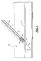
- FIG. 1is a cross-sectional view of the first embodiment of an apparatus for inhibiting blood loss in accordance with the present invention
- FIG. 1 ais a section of the embodiment shown in FIG. 1 .
- FIG. 2is a cross-sectional view of the second embodiment of an apparatus for inhibiting blood loss from a puncture site with a control tip assembly in accordance with the present invention
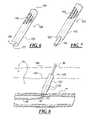
- FIG. 4is a cross-sectional view of a punctured blood vessel and an apparatus for inhibiting blood loss from a puncture site with a control tip assembly (as shown in FIG. 2 ) in accordance with the present invention
- FIG. 5is a cross-sectional view of another embodiment of an apparatus for inhibiting blood loss in accordance with the present invention.
- FIG. 6is another embodiment of the device in accordance with the present invention.
- FIG. 7is an embodiment of the device of the present invention including a retention tip
- FIG. 8is a cross-sectional view of a punctured blood vessel and an apparatus for inhibiting blood loss from a puncture site using the device shown in FIG. 7 .
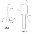
- FIG. 9is another embodiment of a device according to the present invention.
- FIG. 10is another embodiment of a device according to the present invention.
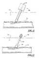
- FIG. 11is a cross-sectional view of a punctured blood vessel and an apparatus for inhibiting blood loss from a puncture site using the device shown in FIG. 10 .
- FIG. 12is a cross-sectional view of a punctured blood vessel and an apparatus for inhibiting blood loss from a puncture site using the device shown in FIG. 9
- FIG. 13is another embodiment of a device according to the present invention.
- FIG. 14is another embodiment of a device according to the present invention.
- FIG. 14 ais another embodiment of a device according to the present invention.
- FIG. 14 bis another embodiment of a device according to the present invention.
- FIG. 15is a conventional biopsy device shown in use.
- FIG. 16is another embodiment of a device according to the present invention as used following a biopsy procedure.
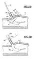
- FIG. 17is another embodiment of a device according to the present invention as used following a biopsy procedure.
- FIG. 18is another embodiment of a device according to the present invention as used following a biopsy procedure.
- FIG. 1illustrates an apparatus 10 for locating a puncture site in a blood vessel wall and for inhibiting blood loss from the puncture site according to the present invention.
- the apparatus 10includes a tube 12 , an elongated member 14 , a dissolvable distal capsule 20 , and sponge 26 located inside the dissolvable distal capsule 20 .
- the elongated member 14has a proximal end 16 and a distal end 18 , and is positioned around the tube 12 .
- the distal end 18 of the elongated member 14has a substantially concave spherical shape.
- the distal end 18 of the elongated member 14can have any concave shape including a rectangular, a stepped or a flat surface which accommodates the sponge 26 located inside the dissolvable distal capsule 20 .
- the elongated member 14has a contact zone 34 in which the elongated member 14 has an outer diameter which is slightly smaller than the outer diameter of the more proximal portion of the elongated member 14 to allow the dissolvable distal capsule 20 to slide onto the contact zone 34 of the elongated member 14 .
- the outer diameter of the elongated member 14 in the contact zone 34is equal to the inner diameter of the dissolvable distal capsule 20
- the outer diameter of the distal capsule 20is equal to the outer diameter of the elongated member proximal to the contact zone 34 to provide a smooth transition from the dissolvable distal capsule 20 to the elongated member 14
- the outer diameter of the elongated member 14 proximal to the contact zone 34is slightly larger than the access sheath or device that occupied the vessel puncture, and preferable 2 Fr larger.
- the tube 12has a proximal end 22 and a distal end 24 and extends longitudinally from the proximal end 16 beyond the distal end 18 of the elongated member 14 .
- the tube 12has an inner diameter of about 0.040 to 0.120 inches, preferably about 0.050 to 0.090 inches, and should loosely accommodate a guidewire 30 , as shown in FIG. 3 .
- the tube 12has a wall thickness of about 0.0005 to 0.005 inches and preferably 0.001 to 0.002 inches.
- the inner diameter 62 of the tube 12is slightly greater than the inner diameter 60 of the tube 12 along its proximal portion to accommodate a cylindrical section 80 of the dissolvable distal capsule 20 .
- the inner diameter 60 of the tube 12is equal to the inner diameter 64 of the edge of the dissolvable distal capsule 20 .
- the tube 12can optionally be coated or otherwise protected with a material which inhibits blood coagulation.
- the tube 12can be coated with material including heparin (e.g. heparinized), tPa, or other functionally similar materials or compounds which inhibit or prevent blood from clotting or otherwise coagulating in the tube 12 .
- the dissolvable distal capsule 20is positioned around the tube 12 , and has a proximal end 67 and a distal end 68 .
- the dissolvable distal capsule 20 and the tube 12form a coaxial space 66 therebetween for the sponge 26 .
- the proximal end 67 of the dissolvable distal capsule 20fits snugly around the distal end 18 of the elongated member 14 and can be attached thereto by adhesive or gelatin solution, or by wetting the capsule so that it becomes sticky prior to positioning the capsule 20 around the tube so that the capsule and the tube are bonded to one another.
- the capsule 20can be held to the elongated member 14 by frictional engagement or by an interlock system such as an annular ring 76 formed in the capsule 20 and a corresponding annular groove 78 formed in the elongated member 14 , as shown in FIG. 1 a.
- an interlock systemsuch as an annular ring 76 formed in the capsule 20 and a corresponding annular groove 78 formed in the elongated member 14 , as shown in FIG. 1 a.
- the dissolvable distal capsule 20includes an outer tubular section having a proximal end 67 and a distal end 68 .
- the proximal end 67is open, having an inner diameter slightly greater than or equal to the outer diameter 36 of the elongated member 14 at the elongated member's distal end 18 .
- the distal end 68 of the dissolvable distal capsule 20is rounded to prevent catching on subcutaneous tissue as the apparatus 10 is inserted through the epidermal outer layer and subcutaneous tissue.
- the distal end of the capsule 20has cylindrical section 80 for receiving the tube 12 .
- the cylindrical section 80has a proximal end 82 and a distal end 84 , and the outer diameter of the cylindrical section 80 is approximately equal to or slightly smaller than the inner diameter of the tube 12 .
- the elongated member 14is preferably a rigid or semi-rigid polymer such as PVC (polyvinyl chloride) or polycarbonate, but may be made of any suitable material, including SST.
- the tube 12can be made from any number of polymers or from thin wall SST.
- the dissolvable distal capsule 20is made from known absorbable, biocompatible materials, such as gelatin films like Gelfilm (R) from Upjohn or like gel-cap vitamins.
- gelatin filmpreferably the hardness of the gelatin film forming the distal capsule is between about 40 and about 80 on the Shore A scale; and preferably it has a bloom of at least 270, which is normally called “high” bloom. However, in some circumstances the gelatin film could have a hardness' and bloom outside these ranges.
- the sponge 26is preferably a liquid permeable, water soluble gelatin based sponge.
- Other hemostatic materialcan be used as well, instead of sponge 26 , such as fibrillar collagen, collagen sponge, regenerated oxidized cellulose, gelatin powder, or hydrogel particles.
- the spongemay be composed of an absorbable collagen or other types of absorbable polymers.
- One type of absorbable sponge material which is acceptable for use in the present inventionis GelfoamTM, manufactured by the Pharmacia & Upjohn Company. GelfoamTM is a porous, pliable, cross-linked gelatin material and is available commercially in sheet form as pre-compressed or non-compressed sponge.
- the spongecan be made by mixing a suitable organic solvent (e.g., formaldehyde) with an aqueous solution of gelatin.
- a suitable organic solvente.g., formaldehyde
- the organic solventfacilitates the cross linkage of gelatin polymers. It is expected that glutaraldehyde may also be suitable.
- the resulting solutionis then incubated typically at slightly above room temperature (30.degree.-40.degree. C.). Thereafter, the solution is aerated to cause it to foam, and the foam is dried to produce the absorbable sponge material.
- Suitable absorbable sponge materialsare described in U.S. Pat. No. 2,465,357 which is incorporated herein by reference.
- FIG. 2illustrates an alternative embodiment of apparatus 10 of FIG. 1 further including a control tip assembly 40 .
- the control tip assembly 40at its proximal end is mounted to a tube 54 .
- the control tip assembly 40includes a proximal end portion 42 , a distal end 46 portion having a distal port 50 , and a central portion 44 between the proximal end portion 42 and the distal end portion 46 .
- the control tip assembly 40includes a lumen 51 which extends longitudinally between proximal end portion 42 and the distal end portion 46 .
- the lumenalso extends through tube 54 .
- the lumen 51can optionally be coated or otherwise provided with an interior surface which inhibits blood coagulation.
- the lumen 51can be coated with material including heparin (e.g. heparinized), tPa, or other functionally similar materials or compounds which inhibit or prevent blood from clotting or otherwise coagulating in the lumen 51 .
- heparine.g. heparinized
- tPae.g. tPa
- other functionally similar materials or compoundswhich inhibit or prevent blood from clotting or otherwise coagulating in the lumen 51 .
- the center portion 44preferably has a constant outer diameter.
- the proximal and distal endsare tapered; however, it can be appreciated that the proximal and distal end portions 42 and 46 can alternatively be a step, rounded shoulder, or the like.
- the control tip assembly 40also includes a hole 52 which connects the exterior of the control tip assembly 40 with the lumen 51 .
- the lumen 51has an inner diameter selected to be larger than the external diameter of a guidewire, preferably an exchange wire, used therewith.
- a plurality of holescan be formed in the control head, circumferentially spaced and at the same longitudinal location as hole 52 .
- the proximal and distal portions 42 , 46 of the control tip assembly 40can be relatively thin walled such that the internal dimensions of the lumen 51 in the central portion 44 is larger than in the proximal end portion 42 and distal portion 46 of the control tip assembly 40 .
- the distal portion 46 of control tip assembly 40includes a distal port 50 having an internal opening diameter also selected to be larger, and preferably only slightly larger, than the external diameter of the guidewire 30 used with the control tip assembly.
- one aspect of the present inventionis that by selecting the external diameter of guidewire 30 and the inner diameter of the distal port 50 to be only slightly different, blood flow into interior of control tip assembly 40 is greatly restricted, thus allowing the hole 52 to be the sole entrance into the control tip for blood to flow up the lumen 51 to indicate that the control tip assembly 40 has been located in a blood vessel.
- control tip assemblyis formed of a flexible, biocompatible material, such as a thermoplastic.
- a flexible, biocompatible materialsuch as a thermoplastic.
- the material out of which the control tip is formedhas a Shore hardness between about 98 A-74 D.
- the outer diameter of the central portion 44is between about 4 French and about 10 French, preferably between about 6 French and about 8 French. It is preferably equal to or similar in diameter to the access sheath that was used to make the puncture.
- the length of the control tip assembly, between the distal most end and the proximal end of the proximal end portion 42should be at least about 1 inch and preferably about 8 inches (6.4 cm), and more preferably about 2 to 4 inches. Control tip assemblies of these dimensions are well suited for controlling puncture sites as described herein, particularly puncture sites used during percutaneous-type vascular access.
- FIG. 3illustrates the operation of the apparatus 10 as shown in FIG. 1 .
- a guidewire 30is advanced through the sheath, into the patient's blood vessel 72 through a puncture site 70 in the vessel wall, and the sheath is removed.
- the apparatus 10is then placed over the guide wire 30 and pushed through the patient's skin.
- the operatoruses the apparatus 10 to locate the desired delivery location by bumping into the artery 72 . Once the desired delivery position is achieved, the operator retracts the tube 12 to expose at least part of the sponge 26 to blood from blood vessel 72 , which starts the process of sponge expansion.
- the dissolvable distal capsule 20is exposed to blood and begins to soften and dissolve.
- the dissolvable distal capsule 20dissolves in about 30 sec. to 10 min. and preferably in about 1 minute.
- the sponge 26is free to expand into the puncture site.
- the dissolvable distal capsule 20will also release itself from the elongated member body 14 as a result of softening and dissolving of the capsule.
- the operatormay apply pressure over the site. The operator can then apply diffuse external pressure to the tissue over the sponge 26 and remove the guidewire 30 and the elongated member 14 .
- FIG. 4The use of the FIG. 2 embodiment of apparatus 10 is shown in FIG. 4 .
- the operatorplaces the control tip assembly 40 over the proximal end of the guidewire 30 which extends from the patient's artery and pushes the apparatus through the patient's skin.
- the apparatus 10locates the desired location by bumping into the arterial puncture site 70 .
- the control tip assembly 40provides additional benefits such as hemostasis and bleedback via the bleedback hole 52 or through the tube 54 .
- the tube 12is retracted to expose the sponge 26 from the puncture site 70 and the blood vessel 72 . This starts the process of sponge 26 expansion.
- the control tip assembly 40can be retracted far enough to control the puncture site 70 .
- the dissolvable distal capsule 20softens and dissolves, releasing the sponge 26 into the puncture site and detaching the sponge 26 from the elongated member 14 .
- the control tip assembly 40is then completely removed from the puncture site 70 and the skin 74 .
- the operatormay apply pressure over the site The operator then applies diffuse external pressure to the tissue over the sponge 26 and removes the guidewire, elongated member 14 and tube 12 , if it has not already been removed.
- the apparatus 90includes an elongated member 94 having a lumen 92 for receiving a guidewire 110 , a dissolvable distal capsule 100 positioned around the lumen 92 and a sponge 116 located inside the dissolvable distal capsule 100 .
- the lumen 92(which is defined by the inner surface of the elongated member 94 ) for receiving the guidewire 110 extends from a proximal end 96 of the elongated member 94 to a distal end 98 of the elongated member 94 .
- a dissolvable distal capsule 100attaches to the distal end 98 of the elongated member 94 as described above.
- the dissolvable capsuleincludes an inner cylindrical portion 102 that extends approximately the same length as the outer cylindrical portion 104 and into at least a portion of the elongated member 94 .
- the capsulehas a rounded end 106 extending between the inner cylindrical portion 102 and the outer cylindrical portion 104 .
- the apparatus 90 as shown in FIG. 5is placed over the proximal end 112 of a guidewire 110 extending from a patient's artery and the apparatus 90 is advanced into the patient.
- the apparatus 90locates the desired delivery location by bumping into the arterial puncture site to obtain the desired delivery position. This starts the process of sponge 116 expansion, wherein the dissolvable distal capsule 100 begins to soften and dissolve rapidly. Once the dissolvable distal capsule 100 has dissolved, the sponge 116 is free to expand into the puncture site and secure itself within the puncture site.
- the dissolvable distal capsule 100will also release itself from the elongated member 94 body as a result of softening and dissolving of the dissolvable distal capsule 100 .
- FIG. 6illustrates another embodiment of the present invention.
- This embodimentshows a hemostasis device 120 including a dissolvable capsule 122 substantially the same as the distal capsule 100 shown in FIG. 5 , with the exception that the hemostasis device of this embodiment is not designed to be connected to an elongated member such as the elongated member 94 shown in FIG. 5 .
- the proximal end 124 of the capsule 122can be open, or it can be closed as is the rounded end 106 .
- FIG. 7illustrates another embodiment similar to the embodiment in FIG. 6 .
- a retention tip 130is affixed to the rounded end 106 .
- the retention tipis substantially cylindrical and the central lumen of the retention tip 130 is coaxial with the lumen of the dissolvable capsule 122 .
- FIG. 8shows another embodiment, which is similar to the embodiment in FIG. 7 .
- a plurality of retention anchors 132are provided on the capsule 122 .
- the retention anchors 132consist of one or more ridges formed around the circumference of the capsule 122 , and their function will be described below.
- the hemostasis device 120is inserted into the patient's skin 74 .
- the operatoruses the retention tip 130 to help maintain the hemostasis device 120 at its proper location relative to the puncture site 70 .
- the retention anchors 132help keep the device located in the proper position while the operator removes the wire 30 and thereafter until the device has dissolved.
- the operatormay insert the hemostasis device so that it extends above the surface of the patient's skin 140 or can push it below the surface of the patient's skin 142 .
- FIG. 9shows another embodiment.
- a proximal dissolvable capsule 144is affixed to the proximal end of a distal dissolvable capsule 145 .
- Both dissolvable capsules 144 and 145contain compressed sponge which is not shown for the purpose of clarity.
- the proximal dissolvable capsule 144has a diameter smaller than the diameter of the distal dissolvable capsule 145 .
- a lumen 146extends through the device.
- FIG. 10shows a placement device 156 to aid in the insertion and placement of a hemostasis device shown in FIG. 9 .
- the placement deviceincludes a cylindrical handle 150 and a cylindrical column 152 affixed to the distal end of the handle.
- a lumen 154is located axially through the handle 150 and column 152 .
- FIGS. 11 and 12illustrate the operation of the devices of FIGS. 9 and 10 .
- the hemostasis device of FIG. 9is inserted into the lumen of the placement device until the proximal part of the distal capsule 145 contacts the distal end of the column 152 .
- the wire 30is inserted through the lumen 146 of the device of FIG. 9 and the operator uses the handle to push the hemostasis device through the patient's skin until the distal dissolvable capsule 145 contacts the outer surface of the blood vessel 72 .
- the operatorretracts the placement device 156 , leaving the hemostasis device in place as shown in FIG. 12 .
- the guide wirecan be removed before or after removal of the placement device 156 .
- FIG. 13illustrates another embodiment.
- This embodimentincludes a control tip assembly 40 as shown in FIG. 2 and described above.
- a proximal gelatin capsule 158is connected to the control tip 40 assembly proximally thereof.
- the proximal gelatin capsule 158consists of a truncated cone-shaped portion 160 and a cylindrical portion 162 connected to the distal end of the cone-shaped portion, both of which are constructed of the same material as the dissolvable distal capsule 20 , e.g. gelatin.
- Located within the proximal gelatin capsule 158is a compressed sponge 164 which is formed of the same material as sponge 26 .
- the proximal gelatin capsule 158includes cylindrical openings at each end to fit snugly over the control tip 40 and snugly over the tube 54 so when an operator pushes the device through a patient's skin there is minimal frictional resistance between the leading edge of the proximal gelatin capsule 158 and the skin. Furthermore, the compressed sponge 164 can be packed tightly against the tube 54 and control tip assembly 40 to provide friction therebetween so that that proximal gelatin capsule 158 remains in place when the operator pushes the device through the patient's skin. Alternatively, the control tip assembly 40 and proximal gelatin capsule 158 may be inserted through a procedural access sheath which is already in place.
- control tip assembly 40is formed of rapidly dissolvable material such as the material of the dissolvable distal capsule 20 , described above with reference to FIG. 1 .
- an operatorinserts the devices through a patient's skin in the same manner as the embodiments described above.
- the capsuledissolves thereby releasing the compressed sponge 164 which provides hemostasis.
- FIG. 14 ashows an embodiment where the distance from the distal end of the proximal gelatin capsule 158 to the hole 52 is located at one of three alternative positions, 52 a , 52 b or 52 c .
- Position 52 ais chosen so that when the assembly 188 is pushed in and the operator is first able to observe bleed back due to blood from inside the vessel 72 entering the hole 52 , the device is properly positioned.
- position 52 ais chosen so that the hole 52 a is located a distance of d 1 from the distal end of the proximal gelatin capsule 158 so that the hemostatic material is released just outside the vessel.
- bleed back hole 52 bis used, which is positioned at d 2 where d 2 is less than d 1 such that the assembly 188 is pushed in until bleed back indication occurs and then withdrawn until bleed back indication first stops in which case the device is properly positioned.
- d 2is chosen to position the hemostatic material just outside the vessel.
- the bleed back hole 52 cmay be used, which is positioned at d 3 where d 3 is less than d 2 so that the assembly 188 is pushed in until bleed back indication occurs and then withdrawn until bleed back first stops and then withdrawn an additional predetermined distance. In the example shown d 3 and the predetermined distance are chosen to position the hemostatic material just outside the vessel.
- the portion of the tube 54 extending proximally of the proximal gelatin capsule 158may have a diameter smaller than the control tip 40 or equal to the control tip 40 . If the tube 54 is smaller than the control tip 40 and the control tip outside diameter is equal to or slightly smaller than the inside diameter of the access sheath 182 , the capsule may be positioned as shown in FIG. 14 b . Starting with the sheath already extending into a vessel 72 , the assembly 188 is pushed in through the sheath 182 until the cylindrical portion 162 extends distally of the distal end 190 of the sheath 182 and bleed back indication is observed via blood entering the distal end 190 of the sheath.
- the assembly 188 and sheath 182are then withdrawn as one until bleed back indication first stops.
- the sheath 182 and assembly 188are then withdrawn an “additional distance” to properly position the hemostatic material.
- the “additional distance”is equal to “T”, the length of the proximal capsule 158 , excluding the length of the cylindrical portion 162 thereof.
- FIG. 15illustrates a conventional biopsy device, including a needle 180 and a guide 182 which has a lumen 184 (show in FIG. 16 ).
- a tissue samplewith the needle 180
- the needleis removed, leaving the guide 182 in place.
- the operatorinserts a hemostasis device 186 through the guide 182 .
- the hemostasis device 186can be formed by rolling a sheet of sponge material tightly to form a cylinder and coating the cylinder with gelatin.
- the operatorcan moisten the surface of the sponge with distilled water so that the surface dissolves slightly and the sponge sticks to itself and retains its rolled configuration.
- the operatorcan then coat the cylindrically formed sponge with a gelatin solution, preferably 5% plus or minus 0.5%, or the operator can insert the cylindrically-formed sponge into a pre-formed gelatin capsule having the appropriate cylindrical shape.
- the operatorcan insert the hemostasis device 186 so that it extends beyond the distal end of the guide 182 so that the hemostasis device 186 contacts the patient's blood and dissolves to create hemostasis.
- the operatorcan remove the guide 182 partially or completely at the appropriate time as the hemostasis device 186 is dissolving.
- FIG. 17illustrates another embodiment wherein the operator of the biopsy device completely removes the guide 182 without inserting the hemostasis device 186 .
- the operatorthen inserts the hemostasis device into the patient's skin 74 . If the hemostasis device is sufficiently long so that when it is completely inserted, a portion remains above the skin surface, the portion remaining above the skin surface can be trimmed off flush with or below the skin surface.
- the hemostasis devicecan be shorter than the depth of the wound in the patient's skin, in which case the operator can push the homeostasis device 186 below the surface of the patient's skin with an appropriate tool such as a rod.
Landscapes
- Health & Medical Sciences (AREA)
- Surgery (AREA)
- Life Sciences & Earth Sciences (AREA)
- Heart & Thoracic Surgery (AREA)
- Animal Behavior & Ethology (AREA)
- General Health & Medical Sciences (AREA)
- Public Health (AREA)
- Veterinary Medicine (AREA)
- Vascular Medicine (AREA)
- Epidemiology (AREA)
- Chemical & Material Sciences (AREA)
- Dispersion Chemistry (AREA)
- Cardiology (AREA)
- Nuclear Medicine, Radiotherapy & Molecular Imaging (AREA)
- Engineering & Computer Science (AREA)
- Biomedical Technology (AREA)
- Medical Informatics (AREA)
- Molecular Biology (AREA)
- Materials For Medical Uses (AREA)
- Surgical Instruments (AREA)
- Medicines Containing Material From Animals Or Micro-Organisms (AREA)
- Compounds Of Unknown Constitution (AREA)
- Medicinal Preparation (AREA)
Abstract
Description
Claims (25)
Priority Applications (11)
| Application Number | Priority Date | Filing Date | Title |
|---|---|---|---|
| US10/287,922US7455680B1 (en) | 2002-11-04 | 2002-11-04 | Apparatus and method for inhibiting blood loss |
| US10/461,587US7955353B1 (en) | 2002-11-04 | 2003-06-12 | Dissolvable closure device |
| US10/462,064US8317821B1 (en) | 2002-11-04 | 2003-06-12 | Release mechanism |
| US10/460,859US7335219B1 (en) | 2002-11-04 | 2003-06-12 | Hemostatic device including a capsule |
| PCT/US2003/035385WO2004041122A2 (en) | 2002-11-04 | 2003-11-04 | Apparatus and method for inhibiting blood loss |
| AU2003287538AAU2003287538A1 (en) | 2002-11-04 | 2003-11-04 | Apparatus and method for inhibiting blood loss |
| EP03781780AEP1572004B1 (en) | 2002-11-04 | 2003-11-04 | Apparatus for inhibiting blood loss |
| CA2503823ACA2503823C (en) | 2002-11-04 | 2003-11-04 | Apparatus and method for inhibiting blood loss |
| CA2782829ACA2782829A1 (en) | 2002-11-04 | 2003-11-04 | Apparatus and method for inhibiting blood loss |
| JP2004550532AJP4476123B2 (en) | 2002-11-04 | 2003-11-04 | Apparatus and method for suppressing blood loss |
| AT03781780TATE518483T1 (en) | 2002-11-04 | 2003-11-04 | DEVICE FOR INHIBITING BLOOD LOSS |
Applications Claiming Priority (1)
| Application Number | Priority Date | Filing Date | Title |
|---|---|---|---|
| US10/287,922US7455680B1 (en) | 2002-11-04 | 2002-11-04 | Apparatus and method for inhibiting blood loss |
Related Parent Applications (1)
| Application Number | Title | Priority Date | Filing Date |
|---|---|---|---|
| US10/462,065Continuation-In-PartUS7695492B1 (en) | 1999-09-23 | 2003-06-12 | Enhanced bleed back system |
Related Child Applications (3)
| Application Number | Title | Priority Date | Filing Date |
|---|---|---|---|
| US10/460,859Continuation-In-PartUS7335219B1 (en) | 2002-11-04 | 2003-06-12 | Hemostatic device including a capsule |
| US10/462,064Continuation-In-PartUS8317821B1 (en) | 2002-11-04 | 2003-06-12 | Release mechanism |
| US10/461,587Continuation-In-PartUS7955353B1 (en) | 2002-11-04 | 2003-06-12 | Dissolvable closure device |
Publications (1)
| Publication Number | Publication Date |
|---|---|
| US7455680B1true US7455680B1 (en) | 2008-11-25 |
Family
ID=32312088
Family Applications (2)
| Application Number | Title | Priority Date | Filing Date |
|---|---|---|---|
| US10/287,922Expired - Fee RelatedUS7455680B1 (en) | 2002-11-04 | 2002-11-04 | Apparatus and method for inhibiting blood loss |
| US10/460,859Expired - Fee RelatedUS7335219B1 (en) | 2002-11-04 | 2003-06-12 | Hemostatic device including a capsule |
Family Applications After (1)
| Application Number | Title | Priority Date | Filing Date |
|---|---|---|---|
| US10/460,859Expired - Fee RelatedUS7335219B1 (en) | 2002-11-04 | 2003-06-12 | Hemostatic device including a capsule |
Country Status (7)
| Country | Link |
|---|---|
| US (2) | US7455680B1 (en) |
| EP (1) | EP1572004B1 (en) |
| JP (1) | JP4476123B2 (en) |
| AT (1) | ATE518483T1 (en) |
| AU (1) | AU2003287538A1 (en) |
| CA (2) | CA2782829A1 (en) |
| WO (1) | WO2004041122A2 (en) |
Cited By (13)
| Publication number | Priority date | Publication date | Assignee | Title |
|---|---|---|---|---|
| US20070160638A1 (en)* | 2006-01-09 | 2007-07-12 | Jack Mentkow | Hemostatic agent delivery system |
| US20080287986A1 (en)* | 2007-05-18 | 2008-11-20 | Possis Medical, Inc. | Closure device |
| US20110137338A1 (en)* | 2009-12-08 | 2011-06-09 | Victor Matthew Phillips | Hemostatic Device and Its Methods of Use |
| US20110166595A1 (en)* | 2010-01-06 | 2011-07-07 | St. Jude Medical, Inc. | Method and system for sealing percutaneous punctures |
| US8524270B2 (en) | 2001-03-12 | 2013-09-03 | Boston Scientific Scimed, Inc. | Cross-linked gelatin composition coated with a wetting agent |
| US8876862B2 (en) | 2011-04-14 | 2014-11-04 | Phillips Medical Llc | Hemostatic device and its methods of use |
| US20160128679A1 (en)* | 2007-01-26 | 2016-05-12 | Med-Trade Products Limited | Haemostat application |
| US9468428B2 (en) | 2012-06-13 | 2016-10-18 | Phillips Medical Llc | Hemostatic device and its methods of use |
| US9642604B2 (en) | 2012-04-12 | 2017-05-09 | Phillips Medical Llc | Hemostatic system and its methods of use |
| US9724081B2 (en) | 2013-06-04 | 2017-08-08 | Phillips Medical Llc | Hemostatic system and its methods of use |
| US9839416B2 (en) | 2013-07-12 | 2017-12-12 | Phillips Medical, LLC | Hemostatic device and its methods of use |
| US9993236B2 (en) | 2009-12-08 | 2018-06-12 | Phillips Medical, LLC | Hemostatic device and its methods of use |
| US10085730B2 (en) | 2013-07-12 | 2018-10-02 | Phillips Medical, LLC | Hemostatic device and its methods of use |
Families Citing this family (21)
| Publication number | Priority date | Publication date | Assignee | Title |
|---|---|---|---|---|
| US8992567B1 (en) | 2001-04-24 | 2015-03-31 | Cardiovascular Technologies Inc. | Compressible, deformable, or deflectable tissue closure devices and method of manufacture |
| US20090143808A1 (en)* | 2001-04-24 | 2009-06-04 | Houser Russell A | Guided Tissue Cutting Device, Method of Use and Kits Therefor |
| US8961541B2 (en) | 2007-12-03 | 2015-02-24 | Cardio Vascular Technologies Inc. | Vascular closure devices, systems, and methods of use |
| US20080109030A1 (en)* | 2001-04-24 | 2008-05-08 | Houser Russell A | Arteriotomy closure devices and techniques |
| US20100168767A1 (en) | 2008-06-30 | 2010-07-01 | Cardiva Medical, Inc. | Apparatus and methods for delivering hemostatic materials for blood vessel closure |
| US8911472B2 (en) | 2005-12-13 | 2014-12-16 | Cardiva Medical, Inc. | Apparatus and methods for delivering hemostatic materials for blood vessel closure |
| US8317822B2 (en)* | 2005-12-22 | 2012-11-27 | Ethicon, Inc. | Systems and methods for closing a vessel wound |
| US8568445B2 (en) | 2007-08-21 | 2013-10-29 | St. Jude Medical Puerto Rico Llc | Extra-vascular sealing device and method |
| US8333787B2 (en) | 2007-12-31 | 2012-12-18 | St. Jude Medical Puerto Rico Llc | Vascular closure device having a flowable sealing material |
| US8840640B2 (en)* | 2007-12-31 | 2014-09-23 | St. Jude Medical Puerto Rico Llc | Vascular closure device having an improved plug |
| CA2668792C (en)* | 2008-06-30 | 2017-08-01 | Tyco Healthcare Group Lp | Valve assembly including a dissolvable valve member |
| US8292918B2 (en) | 2009-02-20 | 2012-10-23 | Boston Scientific Scimed, Inc. | Composite plug for arteriotomy closure and method of use |
| CN101496732B (en)* | 2009-02-24 | 2011-04-06 | 中国人民解放军第三军医大学第一附属医院 | Hemostatic suppository for blocking organ puncture path |
| EP2416711A4 (en)* | 2009-04-09 | 2017-06-07 | Cardiovascular Technologies, Inc. | Tissue closure devices, device and systems for delivery, kits and methods therefor |
| US20130060279A1 (en) | 2011-09-02 | 2013-03-07 | Cardiva Medical, Inc. | Catheter with sealed hydratable hemostatic occlusion element |
| US10792020B2 (en) | 2014-09-18 | 2020-10-06 | Covidien Lp | Tapered geometry in a compressible cell collection device |
| US11096677B2 (en) | 2014-09-18 | 2021-08-24 | Covidien Lp | Regions of varying physical properties in a compressible cell collection device |
| US10751033B2 (en) | 2014-09-18 | 2020-08-25 | Covidien Lp | Use of expansion-force elements in a compressible cell collection device |
| US10531868B2 (en) | 2017-12-01 | 2020-01-14 | Cardiva Medical, Inc. | Apparatus and methods for accessing and closing multiple penetrations on a blood vessel |
| CN110051878A (en)* | 2019-05-28 | 2019-07-26 | 南昌大学第二附属医院 | The preparation method of Pen Zhu Shi Ming gelatin sponge gruel applied to central nervous system surgical hemostasis |
| CN111616787B (en)* | 2020-05-23 | 2022-01-18 | 上海市闵行区中心医院 | Prestress anti-back bone screw assembly |
Citations (123)
| Publication number | Priority date | Publication date | Assignee | Title |
|---|---|---|---|---|
| US2370319A (en) | 1944-11-07 | 1945-02-27 | Dohner & Lippincott | Paper perforator |
| US2874776A (en) | 1954-06-07 | 1959-02-24 | Royal Mcbee Corp | Punch and die mechanism |
| US3358689A (en) | 1964-06-09 | 1967-12-19 | Roehr Products Company Inc | Integral lancet and package |
| US3411505A (en) | 1965-12-15 | 1968-11-19 | Paul D. Nobis | Device for interrupting arterial flow |
| US3724465A (en) | 1971-07-22 | 1973-04-03 | Kimberly Clark Co | Tampon coated with insertion aid and method for coating |
| US3736939A (en) | 1972-01-07 | 1973-06-05 | Kendall & Co | Balloon catheter with soluble tip |
| US4077409A (en)* | 1974-01-24 | 1978-03-07 | Murray Jerome L | Encapsulated catamenial device |
| GB1509023A (en) | 1973-02-12 | 1978-04-26 | Ochsner Med Found Alton | Septal defect closure apparatus |
| US4098728A (en) | 1976-01-02 | 1978-07-04 | Solomon Rosenblatt | Medical surgical sponge and method of making same |
| GB1569660A (en) | 1976-07-30 | 1980-06-18 | Medline Ab | Occlusion of body channels |
| US4211323A (en) | 1978-12-01 | 1980-07-08 | California Medical Developments, Inc. | Disposable diagnostic swab having a stored culture medium |
| US4218155A (en) | 1978-02-10 | 1980-08-19 | Etablissements Armor, S.A. | Stick for applying a liquid |
| US4219026A (en) | 1978-09-15 | 1980-08-26 | The Kendall Company | Bladder hemostatic catheter |
| US4224945A (en) | 1978-08-30 | 1980-09-30 | Jonathan Cohen | Inflatable expansible surgical pressure dressing |
| SU782814A1 (en) | 1977-01-18 | 1980-11-30 | За витель | Prosthesis for closing defect in heart tissues |
| US4238480A (en) | 1978-05-19 | 1980-12-09 | Sawyer Philip Nicholas | Method for preparing an improved hemostatic agent and method of employing the same |
| US4292972A (en) | 1980-07-09 | 1981-10-06 | E. R. Squibb & Sons, Inc. | Lyophilized hydrocolloio foam |
| US4405314A (en) | 1982-04-19 | 1983-09-20 | Cook Incorporated | Apparatus and method for catheterization permitting use of a smaller gage needle |
| US4404970A (en) | 1978-05-19 | 1983-09-20 | Sawyer Philip Nicholas | Hemostatic article and methods for preparing and employing the same |
| SU1088709A1 (en) | 1981-02-10 | 1984-04-30 | Институт Клинической И Экспериментальной Хирургии | Method of treatment of stomach fistula |
| EP0032826B1 (en) | 1980-01-18 | 1984-06-20 | Shiley Incorporated | Vein distention apparatus |
| US4573576A (en) | 1983-10-27 | 1986-03-04 | Krol Thomas C | Percutaneous gastrostomy kit |
| US4644649A (en) | 1985-09-26 | 1987-02-24 | Seaman Roy C | Apparatus for trimming reeds of musical instruments |
| US4699616A (en) | 1986-06-13 | 1987-10-13 | Hollister Incorporated | Catheter retention device and method |
| US4708718A (en) | 1985-07-02 | 1987-11-24 | Target Therapeutics | Hyperthermic treatment of tumors |
| US4832688A (en) | 1986-04-09 | 1989-05-23 | Terumo Kabushiki Kaisha | Catheter for repair of blood vessel |
| US4836204A (en) | 1987-07-06 | 1989-06-06 | Landymore Roderick W | Method for effecting closure of a perforation in the septum of the heart |
| US4839204A (en) | 1987-05-19 | 1989-06-13 | Yazaki Kakoh Co., Ltd. | Resin coated metal pipe having a plane surface for a lightweight structure |
| US4869143A (en) | 1985-06-11 | 1989-09-26 | Merrick Industries, Inc. | Card file punch |
| US4890612A (en) | 1987-02-17 | 1990-01-02 | Kensey Nash Corporation | Device for sealing percutaneous puncture in a vessel |
| WO1991012847A1 (en) | 1990-02-28 | 1991-09-05 | Devices For Vascular Intervention, Inc. | Improved balloon configuration for atherectomy catheter |
| US5049138A (en) | 1989-11-13 | 1991-09-17 | Boston Scientific Corporation | Catheter with dissolvable tip |
| EP0476178A1 (en) | 1990-09-21 | 1992-03-25 | Bioplex Medical B.V. | Device for placing styptic material on perforated blood vessels |
| US5129889A (en) | 1987-11-03 | 1992-07-14 | Hahn John L | Synthetic absorbable epidural catheter |
| US5163904A (en) | 1991-11-12 | 1992-11-17 | Merit Medical Systems, Inc. | Syringe apparatus with attached pressure gauge |
| US5192290A (en) | 1990-08-29 | 1993-03-09 | Applied Medical Resources, Inc. | Embolectomy catheter |
| US5219899A (en) | 1989-04-22 | 1993-06-15 | Degussa Aktiengesellschaft | Pasty dental material which is an organopolysilane filler combined with a polymerizable bonding agent |
| US5232453A (en) | 1989-07-14 | 1993-08-03 | E. R. Squibb & Sons, Inc. | Catheter holder |
| EP0557963A1 (en) | 1992-02-24 | 1993-09-01 | United States Surgical Corporation | Resilient arm mesh deployer |
| US5254105A (en) | 1988-05-26 | 1993-10-19 | Haaga John R | Sheath for wound closure caused by a medical tubular device |
| US5282827A (en) | 1991-11-08 | 1994-02-01 | Kensey Nash Corporation | Hemostatic puncture closure system and method of use |
| WO1994002072A1 (en) | 1992-07-16 | 1994-02-03 | Sherwood Medical Company | Device for sealing hemostatic incisions |
| US5290310A (en)* | 1991-10-30 | 1994-03-01 | Howmedica, Inc. | Hemostatic implant introducer |
| US5310407A (en) | 1991-06-17 | 1994-05-10 | Datascope Investment Corp. | Laparoscopic hemostat delivery system and method for using said system |
| US5320639A (en) | 1993-03-12 | 1994-06-14 | Meadox Medicals, Inc. | Vascular plug delivery system |
| US5322515A (en) | 1993-03-15 | 1994-06-21 | Abbott Laboratories | Luer adapter assembly for emergency syringe |
| US5342388A (en) | 1993-03-25 | 1994-08-30 | Sonia Toller | Method and apparatus for sealing luminal tissue |
| US5350399A (en) | 1991-09-23 | 1994-09-27 | Jay Erlebacher | Percutaneous arterial puncture seal device and insertion tool therefore |
| US5352211A (en) | 1993-07-11 | 1994-10-04 | Louisville Laboratories | External stability device |
| US5370656A (en) | 1993-02-26 | 1994-12-06 | Merocel Corporation | Throat pack |
| WO1994028800A1 (en) | 1993-06-04 | 1994-12-22 | Kensey Nash Corporation | Hemostatic vessel puncture closure with filament lock |
| US5385550A (en) | 1994-03-29 | 1995-01-31 | Su; Chan-Ho | Needle protective means for prevention against stab and virus infection |
| EP0637431A1 (en) | 1993-08-05 | 1995-02-08 | VODA, Jan | Suture device |
| US5399361A (en) | 1992-05-01 | 1995-03-21 | Amgen Inc. | Collagen-containing sponges as drug delivery compositions for proteins |
| FR2641692B1 (en) | 1989-01-17 | 1995-05-12 | Nippon Zeon Co | |
| US5417699A (en) | 1992-12-10 | 1995-05-23 | Perclose Incorporated | Device and method for the percutaneous suturing of a vascular puncture site |
| US5437631A (en)* | 1990-09-21 | 1995-08-01 | Datascope Investment Corp. | Percutaneous introducer set and method for sealing puncture wounds |
| US5437292A (en) | 1993-11-19 | 1995-08-01 | Bioseal, Llc | Method for sealing blood vessel puncture sites |
| US5443481A (en) | 1992-07-27 | 1995-08-22 | Lee; Benjamin I. | Methods and device for percutaneous sealing of arterial puncture sites |
| US5447502A (en) | 1988-05-26 | 1995-09-05 | Haaga; John R. | Sheath for wound closure caused by a medical tubular device |
| US5458570A (en) | 1991-01-22 | 1995-10-17 | May, Jr.; James W. | Absorbable catheter and method of using the same |
| US5462194A (en) | 1995-01-11 | 1995-10-31 | Candea Inc. | Self-venting straw tip |
| WO1995032671A1 (en) | 1994-06-01 | 1995-12-07 | Perclose, Inc. | Method and device for providing vascular hemostasis |
| WO1995032669A1 (en) | 1994-06-01 | 1995-12-07 | Perclose, Inc. | Apparatus and method for advancing surgical knots |
| WO1995032679A1 (en) | 1994-05-31 | 1995-12-07 | Medical Laser Technology, Inc. | Dental laser apparatus and method |
| US5490736A (en) | 1994-09-08 | 1996-02-13 | Habley Medical Technology Corporation | Stylus applicator for a rehydrated multi-constituent medication |
| WO1995028124A3 (en) | 1994-04-08 | 1996-02-15 | Atrix Lab Inc | An adjunctive polymer system for use with medical device |
| US5507279A (en) | 1993-11-30 | 1996-04-16 | Fortune; John B. | Retrograde endotracheal intubation kit |
| US5522850A (en) | 1994-06-23 | 1996-06-04 | Incontrol, Inc. | Defibrillation and method for cardioverting a heart and storing related activity data |
| US5527332A (en) | 1994-11-02 | 1996-06-18 | Mectra Labs, Inc. | Tissue cutter for surgery |
| US5542914A (en) | 1993-02-12 | 1996-08-06 | Kimberly-Clark Corporation | Encapsulated tampon with an applicator |
| US5545178A (en) | 1994-04-29 | 1996-08-13 | Kensey Nash Corporation | System for closing a percutaneous puncture formed by a trocar to prevent tissue at the puncture from herniating |
| US5545175A (en) | 1993-06-18 | 1996-08-13 | Leonard Bloom | Disposable quarded finger scalpel for inserting a line in a patent and lock off therefor |
| WO1996024290A1 (en) | 1995-02-10 | 1996-08-15 | Sherwood Medical Company | Assembly for sealing a puncture in a vessel |
| US5554108A (en)* | 1991-11-06 | 1996-09-10 | Tambrands Inc. | Sanitary tampon |
| US5571168A (en) | 1995-04-05 | 1996-11-05 | Scimed Lifesystems Inc | Pull back stent delivery system |
| US5601603A (en) | 1993-06-16 | 1997-02-11 | White Spot Ag | Use of and process for the introduction of fibrin sealant into a puncture channel |
| US5601601A (en) | 1991-12-13 | 1997-02-11 | Unisurge Holdings, Inc. | Hand held surgical device |
| WO1997009934A1 (en) | 1995-09-15 | 1997-03-20 | Sub-Q, Inc. | Apparatus and method for percutaneous sealing of blood vessel punctures |
| US5620461A (en) | 1989-05-29 | 1997-04-15 | Muijs Van De Moer; Wouter M. | Sealing device |
| EP0637432B1 (en) | 1993-08-03 | 1997-10-01 | Aesculap Ag | Looping instrument |
| US5674346A (en) | 1992-12-15 | 1997-10-07 | Johnson & Johnson Consumer Products, Inc. | Hydrogel laminate, bandages and composites and methods for forming the same |
| US5676689A (en) | 1991-11-08 | 1997-10-14 | Kensey Nash Corporation | Hemostatic puncture closure system including vessel location device and method of use |
| US5681279A (en) | 1996-11-04 | 1997-10-28 | Roper; David H. | Pill dispensing syringe |
| US5716375A (en) | 1990-10-01 | 1998-02-10 | Quinton Instrument Company | Insertion assembly and method of inserting a vessel plug into the body of a patient |
| WO1998006346A1 (en) | 1996-08-12 | 1998-02-19 | Biopsys Medical, Inc. | Apparatus and method for marking tissue |
| US5769086A (en) | 1995-12-06 | 1998-06-23 | Biopsys Medical, Inc. | Control system and method for automated biopsy device |
| US5769813A (en)* | 1995-06-07 | 1998-06-23 | Peiler; Frances K. | Indicator tampon applicator |
| US5775333A (en) | 1994-03-24 | 1998-07-07 | Ethicon Endo-Surgery, Inc. | Apparatus for automated biopsy and collection of soft tissue |
| US5782861A (en) | 1996-12-23 | 1998-07-21 | Sub Q Inc. | Percutaneous hemostasis device |
| US5800389A (en) | 1996-02-09 | 1998-09-01 | Emx, Inc. | Biopsy device |
| US5810806A (en) | 1996-08-29 | 1998-09-22 | Ethicon Endo-Surgery | Methods and devices for collection of soft tissue |
| US5858008A (en) | 1997-04-22 | 1999-01-12 | Becton, Dickinson And Company | Cannula sealing shield assembly |
| US5868762A (en) | 1997-09-25 | 1999-02-09 | Sub-Q, Inc. | Percutaneous hemostatic suturing device and method |
| US5931165A (en) | 1994-09-06 | 1999-08-03 | Fusion Medical Technologies, Inc. | Films having improved characteristics and methods for their preparation and use |
| WO1999066834A1 (en) | 1998-06-22 | 1999-12-29 | Richard Eustis Fulton, Iii | Biopsy localization method and device |
| US6027471A (en) | 1995-01-18 | 2000-02-22 | Fallon; Timothy J. | Apparatus for applying a hemostatic agent onto a tissue |
| US6027482A (en) | 1994-12-12 | 2000-02-22 | Becton Dickinson And Company | Syringe tip cap |
| US6033427A (en) | 1998-01-07 | 2000-03-07 | Lee; Benjamin I. | Method and device for percutaneous sealing of internal puncture sites |
| US6056768A (en) | 1992-01-07 | 2000-05-02 | Cates; Christopher U. | Blood vessel sealing system |
| US6066325A (en) | 1996-08-27 | 2000-05-23 | Fusion Medical Technologies, Inc. | Fragmented polymeric compositions and methods for their use |
| US6071300A (en) | 1995-09-15 | 2000-06-06 | Sub-Q Inc. | Apparatus and method for percutaneous sealing of blood vessel punctures |
| US6071301A (en) | 1998-05-01 | 2000-06-06 | Sub Q., Inc. | Device and method for facilitating hemostasis of a biopsy tract |
| US6126675A (en) | 1999-01-11 | 2000-10-03 | Ethicon, Inc. | Bioabsorbable device and method for sealing vascular punctures |
| US6161034A (en) | 1999-02-02 | 2000-12-12 | Senorx, Inc. | Methods and chemical preparations for time-limited marking of biopsy sites |
| US6162192A (en) | 1998-05-01 | 2000-12-19 | Sub Q, Inc. | System and method for facilitating hemostasis of blood vessel punctures with absorbable sponge |
| US6183497B1 (en) | 1998-05-01 | 2001-02-06 | Sub-Q, Inc. | Absorbable sponge with contrasting agent |
| US6200328B1 (en) | 1998-05-01 | 2001-03-13 | Sub Q, Incorporated | Device and method for facilitating hemostasis of a biopsy tract |
| US6315753B1 (en) | 1998-05-01 | 2001-11-13 | Sub-Q, Inc. | System and method for facilitating hemostasis of blood vessel punctures with absorbable sponge |
| US20020002889A1 (en) | 2000-04-28 | 2002-01-10 | Mark Ashby | Easy cutter |
| US20020016612A1 (en) | 1998-05-01 | 2002-02-07 | Mark Ashby | Device and method for facilitating hemostasis of a biopsy tract |
| US20020042378A1 (en) | 1999-06-10 | 2002-04-11 | Cary J. Reich | Hemoactive compositions and methods for their manufacture and use |
| US20020062104A1 (en) | 1999-09-23 | 2002-05-23 | Mark Ashby | Depth and puncture control for blood vessel hemostasis system |
| US6477534B1 (en) | 1998-05-20 | 2002-11-05 | Lucent Technologies, Inc. | Method and system for generating a statistical summary of a database using a join synopsis |
| US6503222B2 (en) | 2000-09-28 | 2003-01-07 | Pfizer Inc | Oral dosage dispenser |
| US20030028140A1 (en) | 2001-03-12 | 2003-02-06 | Greff Richard J. | Cross-linked gelatin composition comprising a wetting agent |
| US6540735B1 (en) | 2000-05-12 | 2003-04-01 | Sub-Q, Inc. | System and method for facilitating hemostasis of blood vessel punctures with absorbable sponge |
| US6544236B1 (en) | 1999-02-10 | 2003-04-08 | Sub-Q, Incorporated | Device, system and method for improving delivery of hemostatic material |
| US20030088269A1 (en) | 2001-11-08 | 2003-05-08 | Sub-Q, Inc. | System and method for delivering hemostasis promoting material to a blood vessel puncture site by fluid pressure |
| US6610025B2 (en)* | 2001-08-06 | 2003-08-26 | The Procter & Gamble Company | Tampon applicator arrangement |
| US6610026B2 (en) | 1998-05-01 | 2003-08-26 | Sub-Q, Inc. | Method of hydrating a sponge material for delivery to a body |
| US20040019330A1 (en) | 2001-11-08 | 2004-01-29 | Sub-Q, Inc., A California Corporation | Sheath based blood vessel puncture locator and depth indicator |
| US20040019328A1 (en) | 2001-11-08 | 2004-01-29 | Sing Eduardo Chi | System and method for delivering hemostasis promoting material to a blood vessel puncture site by fluid pressure |
Family Cites Families (64)
| Publication number | Priority date | Publication date | Assignee | Title |
|---|---|---|---|---|
| US2899362A (en) | 1959-08-11 | Hemostatic sponges and method of | ||
| US581235A (en) | 1897-04-20 | Island | ||
| US1578517A (en) | 1924-12-23 | 1926-03-30 | George N Hein | Valve piston and barrel construction for hypodermic syringes |
| US2086580A (en) | 1935-06-24 | 1937-07-13 | Myron C Shirley | Applicator |
| US2465357A (en) | 1944-08-14 | 1949-03-29 | Upjohn Co | Therapeutic sponge and method of making |
| US2492458A (en) | 1944-12-08 | 1949-12-27 | Jr Edgar A Bering | Fibrin foam |
| US2507244A (en) | 1947-04-14 | 1950-05-09 | Upjohn Co | Surgical gelatin dusting powder and process for preparing same |
| CH264752A (en) | 1947-06-03 | 1949-10-31 | Hoffmann La Roche | Process for the manufacture of carriers for pharmaceuticals. |
| US2597011A (en) | 1950-07-28 | 1952-05-20 | Us Agriculture | Preparation of starch sponge |
| US2680442A (en) | 1952-04-04 | 1954-06-08 | Frank L Linzmayer | Disposable suppository casing |
| US2814294A (en) | 1953-04-17 | 1957-11-26 | Becton Dickinson Co | Unit for and method of inhibiting and controlling bleeding tendencies |
| US2824092A (en) | 1955-01-04 | 1958-02-18 | Robert E Thompson | Process of preparation of a gelatincarboxymethyl cellulose complex |
| US2761446A (en) | 1955-03-30 | 1956-09-04 | Chemical Specialties Co Inc | Implanter and cartridge |
| US3157524A (en) | 1960-10-25 | 1964-11-17 | Ethicon Inc | Preparation of collagen sponge |
| US4000741A (en) | 1975-11-03 | 1977-01-04 | The Kendall Company | Syringe assembly |
| US4900303A (en) | 1978-03-10 | 1990-02-13 | Lemelson Jerome H | Dispensing catheter and method |
| US4588395A (en) | 1978-03-10 | 1986-05-13 | Lemelson Jerome H | Catheter and method |
| US4340066A (en) | 1980-02-01 | 1982-07-20 | Sherwood Medical Industries Inc. | Medical device for collecting a body sample |
| US4390018A (en) | 1980-09-15 | 1983-06-28 | Zukowski Henry J | Method for preventing loss of spinal fluid after spinal tap |
| NZ205033A (en) | 1982-08-12 | 1986-07-11 | Univ Alabama | Dispensing syringe with longitudinal slits in barrel |
| US4515637A (en) | 1983-11-16 | 1985-05-07 | Seton Company | Collagen-thrombin compositions |
| US4619913A (en) | 1984-05-29 | 1986-10-28 | Matrix Pharmaceuticals, Inc. | Treatments employing drug-containing matrices for introduction into cellular lesion areas |
| US4619261A (en) | 1984-08-09 | 1986-10-28 | Frederico Guerriero | Hydrostatic pressure device for bleeding control through an inflatable, stitchable and retrievable balloon-net system |
| US4587969A (en) | 1985-01-28 | 1986-05-13 | Rolando Gillis | Support assembly for a blood vessel or like organ |
| DE3619197A1 (en)* | 1986-06-07 | 1987-12-10 | Ethicon Gmbh | UPHOLSTERY IMPLANT |
| US4852568A (en) | 1987-02-17 | 1989-08-01 | Kensey Nash Corporation | Method and apparatus for sealing an opening in tissue of a living being |
| US4744364A (en) | 1987-02-17 | 1988-05-17 | Intravascular Surgical Instruments, Inc. | Device for sealing percutaneous puncture in a vessel |
| EP0292936B1 (en) | 1987-05-26 | 1996-03-06 | Sumitomo Pharmaceuticals Company, Limited | Device for administering solid preparations |
| US4829994A (en) | 1987-05-27 | 1989-05-16 | Kurth Paul A | Femoral compression device for post-catheterization hemostasis |
| US4850960A (en) | 1987-07-08 | 1989-07-25 | Joseph Grayzel | Diagonally tapered, bevelled tip introducing catheter and sheath and method for insertion |
| US4790819A (en) | 1987-08-24 | 1988-12-13 | American Cyanamid Company | Fibrin clot delivery device and method |
| US5195988A (en) | 1988-05-26 | 1993-03-23 | Haaga John R | Medical needle with removable sheath |
| US5080655A (en) | 1988-05-26 | 1992-01-14 | Haaga John R | Medical biopsy needle |
| US4936835A (en) | 1988-05-26 | 1990-06-26 | Haaga John R | Medical needle with bioabsorbable tip |
| US5053046A (en) | 1988-08-22 | 1991-10-01 | Woodrow W. Janese | Dural sealing needle and method of use |
| US4929246A (en) | 1988-10-27 | 1990-05-29 | C. R. Bard, Inc. | Method for closing and sealing an artery after removing a catheter |
| US5007895A (en) | 1989-04-05 | 1991-04-16 | Burnett George S | Wound packing instrument |
| GB8916781D0 (en) | 1989-07-21 | 1989-09-06 | Nycomed As | Compositions |
| US5061274A (en) | 1989-12-04 | 1991-10-29 | Kensey Nash Corporation | Plug device for sealing openings and method of use |
| US5021059A (en) | 1990-05-07 | 1991-06-04 | Kensey Nash Corporation | Plug device with pulley for sealing punctures in tissue and methods of use |
| US5299581A (en)* | 1990-07-05 | 1994-04-05 | Donnell John T | Intravaginal device |
| US5192300A (en) | 1990-10-01 | 1993-03-09 | Quinton Instrument Company | Insertion assembly and method of inserting a vessel plug into the body of a patient |
| US5167624A (en) | 1990-11-09 | 1992-12-01 | Catheter Research, Inc. | Embolus delivery system and method |
| US5366480A (en) | 1990-12-24 | 1994-11-22 | American Cyanamid Company | Synthetic elastomeric buttressing pledget |
| US5221259A (en) | 1990-12-27 | 1993-06-22 | Novoste Corporation | Wound treating device and method of using same |
| US5419765A (en) | 1990-12-27 | 1995-05-30 | Novoste Corporation | Wound treating device and method for treating wounds |
| US5810810A (en)* | 1992-04-23 | 1998-09-22 | Scimed Life Systems, Inc. | Apparatus and method for sealing vascular punctures |
| US5220926A (en) | 1992-07-13 | 1993-06-22 | Jones George T | Finger mounted core biopsy guide |
| CZ281454B6 (en) | 1992-11-23 | 1996-10-16 | Milan Mudr. Csc. Krajíček | Aid for non-surgical closing of a hole in a vessel wall |
| US5334216A (en) | 1992-12-10 | 1994-08-02 | Howmedica Inc. | Hemostatic plug |
| FI953546L (en) | 1993-01-25 | 1995-09-22 | Sonus Pharma Inc | Phase-transfer colloids as ultrasound contrast agents |
| US5388588A (en) | 1993-05-04 | 1995-02-14 | Nabai; Hossein | Biopsy wound closure device and method |
| US5383896A (en) | 1993-05-25 | 1995-01-24 | Gershony; Gary | Vascular sealing device |
| US5325857A (en) | 1993-07-09 | 1994-07-05 | Hossein Nabai | Skin biopsy device and method |
| US5486195A (en) | 1993-07-26 | 1996-01-23 | Myers; Gene | Method and apparatus for arteriotomy closure |
| US5431639A (en) | 1993-08-12 | 1995-07-11 | Boston Scientific Corporation | Treating wounds caused by medical procedures |
| US5653730A (en) | 1993-09-28 | 1997-08-05 | Hemodynamics, Inc. | Surface opening adhesive sealer |
| US5383899A (en) | 1993-09-28 | 1995-01-24 | Hammerslag; Julius G. | Method of using a surface opening adhesive sealer |
| JPH09504719A (en)* | 1993-11-03 | 1997-05-13 | クラリオン、ファーマシューティカルズ、インコーポレイテッド | Hemostatic patch |
| US5649547A (en) | 1994-03-24 | 1997-07-22 | Biopsys Medical, Inc. | Methods and devices for automated biopsy and collection of soft tissue |
| JPH10508504A (en) | 1994-09-16 | 1998-08-25 | バイオプシス メディカル インコーポレイテッド | Method and apparatus for identifying and marking tissue |
| WO1998031287A1 (en)* | 1997-01-21 | 1998-07-23 | Tyco Group S.A.R.L. | Bioabsorbable hemostatic sealing assembly |
| US6197327B1 (en)* | 1997-06-11 | 2001-03-06 | Umd, Inc. | Device and method for treatment of dysmenorrhea |
| US7166133B2 (en)* | 2002-06-13 | 2007-01-23 | Kensey Nash Corporation | Devices and methods for treating defects in the tissue of a living being |
- 2002
- 2002-11-04USUS10/287,922patent/US7455680B1/ennot_activeExpired - Fee Related
- 2003
- 2003-06-12USUS10/460,859patent/US7335219B1/ennot_activeExpired - Fee Related
- 2003-11-04WOPCT/US2003/035385patent/WO2004041122A2/enactiveApplication Filing
- 2003-11-04CACA2782829Apatent/CA2782829A1/ennot_activeAbandoned
- 2003-11-04JPJP2004550532Apatent/JP4476123B2/ennot_activeExpired - Lifetime
- 2003-11-04AUAU2003287538Apatent/AU2003287538A1/ennot_activeAbandoned
- 2003-11-04ATAT03781780Tpatent/ATE518483T1/ennot_activeIP Right Cessation
- 2003-11-04CACA2503823Apatent/CA2503823C/ennot_activeExpired - Fee Related
- 2003-11-04EPEP03781780Apatent/EP1572004B1/ennot_activeExpired - Lifetime
Patent Citations (143)
| Publication number | Priority date | Publication date | Assignee | Title |
|---|---|---|---|---|
| US2370319A (en) | 1944-11-07 | 1945-02-27 | Dohner & Lippincott | Paper perforator |
| US2874776A (en) | 1954-06-07 | 1959-02-24 | Royal Mcbee Corp | Punch and die mechanism |
| US3358689A (en) | 1964-06-09 | 1967-12-19 | Roehr Products Company Inc | Integral lancet and package |
| US3411505A (en) | 1965-12-15 | 1968-11-19 | Paul D. Nobis | Device for interrupting arterial flow |
| US3724465A (en) | 1971-07-22 | 1973-04-03 | Kimberly Clark Co | Tampon coated with insertion aid and method for coating |
| US3736939A (en) | 1972-01-07 | 1973-06-05 | Kendall & Co | Balloon catheter with soluble tip |
| GB1509023A (en) | 1973-02-12 | 1978-04-26 | Ochsner Med Found Alton | Septal defect closure apparatus |
| US4077409A (en)* | 1974-01-24 | 1978-03-07 | Murray Jerome L | Encapsulated catamenial device |
| US4098728A (en) | 1976-01-02 | 1978-07-04 | Solomon Rosenblatt | Medical surgical sponge and method of making same |
| GB1569660A (en) | 1976-07-30 | 1980-06-18 | Medline Ab | Occlusion of body channels |
| SU782814A1 (en) | 1977-01-18 | 1980-11-30 | За витель | Prosthesis for closing defect in heart tissues |
| US4218155A (en) | 1978-02-10 | 1980-08-19 | Etablissements Armor, S.A. | Stick for applying a liquid |
| US4404970A (en) | 1978-05-19 | 1983-09-20 | Sawyer Philip Nicholas | Hemostatic article and methods for preparing and employing the same |
| US4238480A (en) | 1978-05-19 | 1980-12-09 | Sawyer Philip Nicholas | Method for preparing an improved hemostatic agent and method of employing the same |
| US4224945A (en) | 1978-08-30 | 1980-09-30 | Jonathan Cohen | Inflatable expansible surgical pressure dressing |
| US4219026A (en) | 1978-09-15 | 1980-08-26 | The Kendall Company | Bladder hemostatic catheter |
| US4211323A (en) | 1978-12-01 | 1980-07-08 | California Medical Developments, Inc. | Disposable diagnostic swab having a stored culture medium |
| EP0032826B1 (en) | 1980-01-18 | 1984-06-20 | Shiley Incorporated | Vein distention apparatus |
| US4292972A (en) | 1980-07-09 | 1981-10-06 | E. R. Squibb & Sons, Inc. | Lyophilized hydrocolloio foam |
| SU1088709A1 (en) | 1981-02-10 | 1984-04-30 | Институт Клинической И Экспериментальной Хирургии | Method of treatment of stomach fistula |
| US4405314A (en) | 1982-04-19 | 1983-09-20 | Cook Incorporated | Apparatus and method for catheterization permitting use of a smaller gage needle |
| US4573576A (en) | 1983-10-27 | 1986-03-04 | Krol Thomas C | Percutaneous gastrostomy kit |
| US4869143A (en) | 1985-06-11 | 1989-09-26 | Merrick Industries, Inc. | Card file punch |
| US4708718A (en) | 1985-07-02 | 1987-11-24 | Target Therapeutics | Hyperthermic treatment of tumors |
| US4644649A (en) | 1985-09-26 | 1987-02-24 | Seaman Roy C | Apparatus for trimming reeds of musical instruments |
| US4832688A (en) | 1986-04-09 | 1989-05-23 | Terumo Kabushiki Kaisha | Catheter for repair of blood vessel |
| US4699616A (en) | 1986-06-13 | 1987-10-13 | Hollister Incorporated | Catheter retention device and method |
| US4890612A (en) | 1987-02-17 | 1990-01-02 | Kensey Nash Corporation | Device for sealing percutaneous puncture in a vessel |
| US4839204A (en) | 1987-05-19 | 1989-06-13 | Yazaki Kakoh Co., Ltd. | Resin coated metal pipe having a plane surface for a lightweight structure |
| US4836204A (en) | 1987-07-06 | 1989-06-06 | Landymore Roderick W | Method for effecting closure of a perforation in the septum of the heart |
| US5129889A (en) | 1987-11-03 | 1992-07-14 | Hahn John L | Synthetic absorbable epidural catheter |
| US5447502A (en) | 1988-05-26 | 1995-09-05 | Haaga; John R. | Sheath for wound closure caused by a medical tubular device |
| US5254105A (en) | 1988-05-26 | 1993-10-19 | Haaga John R | Sheath for wound closure caused by a medical tubular device |
| FR2641692B1 (en) | 1989-01-17 | 1995-05-12 | Nippon Zeon Co | |
| US5219899A (en) | 1989-04-22 | 1993-06-15 | Degussa Aktiengesellschaft | Pasty dental material which is an organopolysilane filler combined with a polymerizable bonding agent |
| US5620461A (en) | 1989-05-29 | 1997-04-15 | Muijs Van De Moer; Wouter M. | Sealing device |
| US5232453A (en) | 1989-07-14 | 1993-08-03 | E. R. Squibb & Sons, Inc. | Catheter holder |
| US5049138A (en) | 1989-11-13 | 1991-09-17 | Boston Scientific Corporation | Catheter with dissolvable tip |
| WO1991012847A1 (en) | 1990-02-28 | 1991-09-05 | Devices For Vascular Intervention, Inc. | Improved balloon configuration for atherectomy catheter |
| US5192290A (en) | 1990-08-29 | 1993-03-09 | Applied Medical Resources, Inc. | Embolectomy catheter |
| US5830130A (en) | 1990-09-21 | 1998-11-03 | Datascope Investment Corp. | Device and method for sealing puncture wounds |
| US5437631A (en)* | 1990-09-21 | 1995-08-01 | Datascope Investment Corp. | Percutaneous introducer set and method for sealing puncture wounds |
| EP0476178A1 (en) | 1990-09-21 | 1992-03-25 | Bioplex Medical B.V. | Device for placing styptic material on perforated blood vessels |
| US5716375A (en) | 1990-10-01 | 1998-02-10 | Quinton Instrument Company | Insertion assembly and method of inserting a vessel plug into the body of a patient |
| US5458570A (en) | 1991-01-22 | 1995-10-17 | May, Jr.; James W. | Absorbable catheter and method of using the same |
| US5310407A (en) | 1991-06-17 | 1994-05-10 | Datascope Investment Corp. | Laparoscopic hemostat delivery system and method for using said system |
| US5350399A (en) | 1991-09-23 | 1994-09-27 | Jay Erlebacher | Percutaneous arterial puncture seal device and insertion tool therefore |
| US5290310A (en)* | 1991-10-30 | 1994-03-01 | Howmedica, Inc. | Hemostatic implant introducer |
| US5324306A (en)* | 1991-10-30 | 1994-06-28 | Howmedica, Inc. | Hemostatic implant introducer |
| US5554108A (en)* | 1991-11-06 | 1996-09-10 | Tambrands Inc. | Sanitary tampon |
| US5676689A (en) | 1991-11-08 | 1997-10-14 | Kensey Nash Corporation | Hemostatic puncture closure system including vessel location device and method of use |
| US5707393A (en) | 1991-11-08 | 1998-01-13 | Kensey Nash Corporation | Hemostatic puncture closure system and method of use |
| US5282827A (en) | 1991-11-08 | 1994-02-01 | Kensey Nash Corporation | Hemostatic puncture closure system and method of use |
| US6007563A (en) | 1991-11-08 | 1999-12-28 | Kensey Nash Corporation | Method of deploying percutaneous puncture closure |
| US6090130A (en) | 1991-11-08 | 2000-07-18 | Kensey Nash Corporation | Hemostatic puncture closure system including blood vessel locator and method of use |
| US5163904A (en) | 1991-11-12 | 1992-11-17 | Merit Medical Systems, Inc. | Syringe apparatus with attached pressure gauge |
| US5601601A (en) | 1991-12-13 | 1997-02-11 | Unisurge Holdings, Inc. | Hand held surgical device |
| US6056768A (en) | 1992-01-07 | 2000-05-02 | Cates; Christopher U. | Blood vessel sealing system |
| EP0557963A1 (en) | 1992-02-24 | 1993-09-01 | United States Surgical Corporation | Resilient arm mesh deployer |
| US5399361A (en) | 1992-05-01 | 1995-03-21 | Amgen Inc. | Collagen-containing sponges as drug delivery compositions for proteins |
| WO1994002072A1 (en) | 1992-07-16 | 1994-02-03 | Sherwood Medical Company | Device for sealing hemostatic incisions |
| US5540715A (en) | 1992-07-16 | 1996-07-30 | Sherwood Medical Company | Device for sealing hemostatic incisions |
| US5443481A (en) | 1992-07-27 | 1995-08-22 | Lee; Benjamin I. | Methods and device for percutaneous sealing of arterial puncture sites |
| US5417699A (en) | 1992-12-10 | 1995-05-23 | Perclose Incorporated | Device and method for the percutaneous suturing of a vascular puncture site |
| US5674346A (en) | 1992-12-15 | 1997-10-07 | Johnson & Johnson Consumer Products, Inc. | Hydrogel laminate, bandages and composites and methods for forming the same |
| US5542914A (en) | 1993-02-12 | 1996-08-06 | Kimberly-Clark Corporation | Encapsulated tampon with an applicator |
| US5370656A (en) | 1993-02-26 | 1994-12-06 | Merocel Corporation | Throat pack |
| US5320639A (en) | 1993-03-12 | 1994-06-14 | Meadox Medicals, Inc. | Vascular plug delivery system |
| US5322515A (en) | 1993-03-15 | 1994-06-21 | Abbott Laboratories | Luer adapter assembly for emergency syringe |
| US5342388A (en) | 1993-03-25 | 1994-08-30 | Sonia Toller | Method and apparatus for sealing luminal tissue |
| WO1994028800A1 (en) | 1993-06-04 | 1994-12-22 | Kensey Nash Corporation | Hemostatic vessel puncture closure with filament lock |
| US5601603A (en) | 1993-06-16 | 1997-02-11 | White Spot Ag | Use of and process for the introduction of fibrin sealant into a puncture channel |
| US5545175A (en) | 1993-06-18 | 1996-08-13 | Leonard Bloom | Disposable quarded finger scalpel for inserting a line in a patent and lock off therefor |
| US5352211A (en) | 1993-07-11 | 1994-10-04 | Louisville Laboratories | External stability device |
| EP0637432B1 (en) | 1993-08-03 | 1997-10-01 | Aesculap Ag | Looping instrument |
| EP0637431A1 (en) | 1993-08-05 | 1995-02-08 | VODA, Jan | Suture device |
| US5437292A (en) | 1993-11-19 | 1995-08-01 | Bioseal, Llc | Method for sealing blood vessel puncture sites |
| US5507279A (en) | 1993-11-30 | 1996-04-16 | Fortune; John B. | Retrograde endotracheal intubation kit |
| US5775333A (en) | 1994-03-24 | 1998-07-07 | Ethicon Endo-Surgery, Inc. | Apparatus for automated biopsy and collection of soft tissue |
| US5385550A (en) | 1994-03-29 | 1995-01-31 | Su; Chan-Ho | Needle protective means for prevention against stab and virus infection |
| WO1995028124A3 (en) | 1994-04-08 | 1996-02-15 | Atrix Lab Inc | An adjunctive polymer system for use with medical device |
| US5545178A (en) | 1994-04-29 | 1996-08-13 | Kensey Nash Corporation | System for closing a percutaneous puncture formed by a trocar to prevent tissue at the puncture from herniating |
| WO1995032679A1 (en) | 1994-05-31 | 1995-12-07 | Medical Laser Technology, Inc. | Dental laser apparatus and method |
| WO1995032669A1 (en) | 1994-06-01 | 1995-12-07 | Perclose, Inc. | Apparatus and method for advancing surgical knots |
| WO1995032671A1 (en) | 1994-06-01 | 1995-12-07 | Perclose, Inc. | Method and device for providing vascular hemostasis |
| US5522850A (en) | 1994-06-23 | 1996-06-04 | Incontrol, Inc. | Defibrillation and method for cardioverting a heart and storing related activity data |
| US5931165A (en) | 1994-09-06 | 1999-08-03 | Fusion Medical Technologies, Inc. | Films having improved characteristics and methods for their preparation and use |
| US5490736A (en) | 1994-09-08 | 1996-02-13 | Habley Medical Technology Corporation | Stylus applicator for a rehydrated multi-constituent medication |
| US5527332A (en) | 1994-11-02 | 1996-06-18 | Mectra Labs, Inc. | Tissue cutter for surgery |
| US6027482A (en) | 1994-12-12 | 2000-02-22 | Becton Dickinson And Company | Syringe tip cap |
| US5462194A (en) | 1995-01-11 | 1995-10-31 | Candea Inc. | Self-venting straw tip |
| US6027471A (en) | 1995-01-18 | 2000-02-22 | Fallon; Timothy J. | Apparatus for applying a hemostatic agent onto a tissue |
| WO1996024290A1 (en) | 1995-02-10 | 1996-08-15 | Sherwood Medical Company | Assembly for sealing a puncture in a vessel |
| US5571168A (en) | 1995-04-05 | 1996-11-05 | Scimed Lifesystems Inc | Pull back stent delivery system |
| US5769813A (en)* | 1995-06-07 | 1998-06-23 | Peiler; Frances K. | Indicator tampon applicator |
| US6071300A (en) | 1995-09-15 | 2000-06-06 | Sub-Q Inc. | Apparatus and method for percutaneous sealing of blood vessel punctures |
| US5645566A (en) | 1995-09-15 | 1997-07-08 | Sub Q Inc. | Apparatus and method for percutaneous sealing of blood vessel punctures |
| US6371974B1 (en) | 1995-09-15 | 2002-04-16 | Sub Q, Inc. | Apparatus and method for percutaneous sealing of blood vessel punctures |
| WO1997009934A1 (en) | 1995-09-15 | 1997-03-20 | Sub-Q, Inc. | Apparatus and method for percutaneous sealing of blood vessel punctures |
| US20020156495A1 (en) | 1995-09-15 | 2002-10-24 | Rodney Brenneman | Apparatus and method for percutaneous sealing of blood vessel punctures |
| US5769086A (en) | 1995-12-06 | 1998-06-23 | Biopsys Medical, Inc. | Control system and method for automated biopsy device |
| US5800389A (en) | 1996-02-09 | 1998-09-01 | Emx, Inc. | Biopsy device |
| US5902310A (en) | 1996-08-12 | 1999-05-11 | Ethicon Endo-Surgery, Inc. | Apparatus and method for marking tissue |
| WO1998006346A1 (en) | 1996-08-12 | 1998-02-19 | Biopsys Medical, Inc. | Apparatus and method for marking tissue |
| US6066325A (en) | 1996-08-27 | 2000-05-23 | Fusion Medical Technologies, Inc. | Fragmented polymeric compositions and methods for their use |
| US5810806A (en) | 1996-08-29 | 1998-09-22 | Ethicon Endo-Surgery | Methods and devices for collection of soft tissue |
| US5681279A (en) | 1996-11-04 | 1997-10-28 | Roper; David H. | Pill dispensing syringe |
| US5984950A (en) | 1996-12-23 | 1999-11-16 | Sub-Q, Inc. | Percutaneous hemostasis device |
| US5782861A (en) | 1996-12-23 | 1998-07-21 | Sub Q Inc. | Percutaneous hemostasis device |
| US5858008A (en) | 1997-04-22 | 1999-01-12 | Becton, Dickinson And Company | Cannula sealing shield assembly |
| US5868762A (en) | 1997-09-25 | 1999-02-09 | Sub-Q, Inc. | Percutaneous hemostatic suturing device and method |
| US6033427A (en) | 1998-01-07 | 2000-03-07 | Lee; Benjamin I. | Method and device for percutaneous sealing of internal puncture sites |
| US6086607A (en) | 1998-05-01 | 2000-07-11 | Sub-Q, Inc. | Device and method for facilitating hemostasis of a biopsy tract |
| US20030135237A1 (en) | 1998-05-01 | 2003-07-17 | Cragg Andrew H. | Device, system and method for improving delivery of hemostatic material |
| US20030088271A1 (en) | 1998-05-01 | 2003-05-08 | Cragg Andrew M. | System and method for facilitating hemostasis of blood vessel punctures with absorbable sponge |
| US6162192A (en) | 1998-05-01 | 2000-12-19 | Sub Q, Inc. | System and method for facilitating hemostasis of blood vessel punctures with absorbable sponge |
| US6183497B1 (en) | 1998-05-01 | 2001-02-06 | Sub-Q, Inc. | Absorbable sponge with contrasting agent |
| US6200328B1 (en) | 1998-05-01 | 2001-03-13 | Sub Q, Incorporated | Device and method for facilitating hemostasis of a biopsy tract |
| US6315753B1 (en) | 1998-05-01 | 2001-11-13 | Sub-Q, Inc. | System and method for facilitating hemostasis of blood vessel punctures with absorbable sponge |
| US6527734B2 (en) | 1998-05-01 | 2003-03-04 | Sub-Q, Inc. | System and method for facilitating hemostasis of blood vessel punctures with absorbable sponge |
| US20020016612A1 (en) | 1998-05-01 | 2002-02-07 | Mark Ashby | Device and method for facilitating hemostasis of a biopsy tract |
| US20020038133A1 (en) | 1998-05-01 | 2002-03-28 | Sing Eduardo Chi | Absorbable sponge with contrasting agent |
| US6071301A (en) | 1998-05-01 | 2000-06-06 | Sub Q., Inc. | Device and method for facilitating hemostasis of a biopsy tract |
| US6440153B2 (en) | 1998-05-01 | 2002-08-27 | Sub-Q, Inc. | Device and method for facilitating hemostasis of a biopsy tract |
| US6610026B2 (en) | 1998-05-01 | 2003-08-26 | Sub-Q, Inc. | Method of hydrating a sponge material for delivery to a body |
| US6440151B1 (en) | 1998-05-01 | 2002-08-27 | Sub-Q, Inc. | Device and method for facilitating hemostasis of a biopsy tract |
| US6477534B1 (en) | 1998-05-20 | 2002-11-05 | Lucent Technologies, Inc. | Method and system for generating a statistical summary of a database using a join synopsis |
| WO1999066834A1 (en) | 1998-06-22 | 1999-12-29 | Richard Eustis Fulton, Iii | Biopsy localization method and device |
| US6126675A (en) | 1999-01-11 | 2000-10-03 | Ethicon, Inc. | Bioabsorbable device and method for sealing vascular punctures |
| US6161034A (en) | 1999-02-02 | 2000-12-12 | Senorx, Inc. | Methods and chemical preparations for time-limited marking of biopsy sites |
| US6544236B1 (en) | 1999-02-10 | 2003-04-08 | Sub-Q, Incorporated | Device, system and method for improving delivery of hemostatic material |
| US20020042378A1 (en) | 1999-06-10 | 2002-04-11 | Cary J. Reich | Hemoactive compositions and methods for their manufacture and use |
| US20020062104A1 (en) | 1999-09-23 | 2002-05-23 | Mark Ashby | Depth and puncture control for blood vessel hemostasis system |
| US6984219B2 (en)* | 1999-09-23 | 2006-01-10 | Mark Ashby | Depth and puncture control for blood vessel hemostasis system |
| US20020002889A1 (en) | 2000-04-28 | 2002-01-10 | Mark Ashby | Easy cutter |
| US6540735B1 (en) | 2000-05-12 | 2003-04-01 | Sub-Q, Inc. | System and method for facilitating hemostasis of blood vessel punctures with absorbable sponge |
| US20030120258A1 (en) | 2000-05-12 | 2003-06-26 | Mark Ashby | System and method for facilitating hemostasis of blood vessel punctures with absorbable sponge |
| US6503222B2 (en) | 2000-09-28 | 2003-01-07 | Pfizer Inc | Oral dosage dispenser |
| US20030028140A1 (en) | 2001-03-12 | 2003-02-06 | Greff Richard J. | Cross-linked gelatin composition comprising a wetting agent |
| US6610025B2 (en)* | 2001-08-06 | 2003-08-26 | The Procter & Gamble Company | Tampon applicator arrangement |
| US20030088269A1 (en) | 2001-11-08 | 2003-05-08 | Sub-Q, Inc. | System and method for delivering hemostasis promoting material to a blood vessel puncture site by fluid pressure |
| US20040019330A1 (en) | 2001-11-08 | 2004-01-29 | Sub-Q, Inc., A California Corporation | Sheath based blood vessel puncture locator and depth indicator |
| US20040019328A1 (en) | 2001-11-08 | 2004-01-29 | Sing Eduardo Chi | System and method for delivering hemostasis promoting material to a blood vessel puncture site by fluid pressure |
Non-Patent Citations (44)
| Title |
|---|
| "Gelfoam Sterile Powder absorbable gelatin powder", Source: Medi-Spart Select, Feb. 1996. |
| Allison, "Percutaneous Liver Biopsy and Track Embolization with Steel Coils", Radiology 1988; 169:261-263. |
| Ashby, Mark et al, U.S. Appl. No. 10/462,064, filed Jun. 12, 2003; entitled: "Release Mechanism". |
| Ashby, Mark et al.; U.S. Appl. No. 10/164,006, filed Jun. 13, 2003; entitled: "System and Method for Delivering Hemostasis Promoting Material to a Blood Vessel Puncture with a Staging Tube". |
| Ashby, Mark et al; U.S. Appl. No. 10/069,107, filed Dec. 16, 2002; entitled: Device And Method For Determining A Depth Of An Incision. |
| Ashby, Mark et al; U.S. Appl. No. 10/278,710, filed Oct. 22, 2002; entitled: "System and Method for Facilitating Hemostasis of Blood Vessel Punctures With Absorbable Sponge". |
| Ashby, Mark et al; U.S. Appl. No. 10/287,922, filed Nov. 4, 2002; entitled: Apparatus And Method For Inhibiting Blood Loss. |
| Ashby, Mark et al; U.S. Appl. No. 10/334,770; filed Dec. 31, 2002; entitled: "Improved System and Method for Facilitating Hemostasis with Absorbable Sponge". |
| Ashby, Mark et al; U.S. Appl. No. 10/421,680, filed Apr. 22, 2003; entitled: "Puncture Closure System With Pin And Pull Technique". |
| Ashby, Mark et al; U.S. Appl. No. 10/460,859, filed Jun. 12, 2003; entitled: "Hemostatic Device Including a Capsule". |
| Ashby, Mark et al; U.S. Appl. No. 10/461,035, filed Jun. 13, 2003; entitled: "System And Method For Delivering Hemostasis Promoting Material To A Blood Vessel Puncture Site Using a Cannula". |
| Ashby, Mark et al; U.S. Appl. No. 10/461,587, filed Jun. 12, 2003; entitled: "Dissolvable Closure Device". |
| Ashby, Mark et al; U.S. Appl. No. 10/462,065, filed Jun. 12, 2003; entitled: "Enhanced Bleed Back System". |
| Ashby, Mark et al; U.S. Appl. No. 10/732,441, filed Dec. 9, 2003; entitled: "Pledget-Handling System and Method for Delivering Hemostasis Promoting Material to a Blood Vessel Puncture Site By Fluid Pressure". |
| Ashby, Mark et al; U.S. Appl. No. 10/754,824, filed Jan. 9, 2004; entitled: "Sheath-Mounted Arterial Plug Delivery Device". |
| Berman et al "Modification of the Cope Drainage Catheter to Facilitate Placement" AJR 146:169-170, 1/86 0361-803X/86/1461-0169 (C) American Ray Society. |
| Berman et al "Modification of the Cope Drainage Catheter to Facilitate Placement" AJR 146:169-170, 1/86 0361-803X/86/1461-0169 © American Ray Society. |
| Berman, Howard L., et al., "Guided Direct Antegrade Puncture of the Superficial Femoral Artry," American Roantgen Ray Society, pp. 632-634 (Sep. 1986). |
| Chuang, "Sheath Needle for Liver Biopsy in High-Risk Patients" Radiology 1998; 166:261-262. |
| Correll, John T. et al. "Biologic investigations of new absorbable sponge"; p. 585. |
| Correll, John T. et al., "Certain Properties of a new Physiologically absorbable sponge" pp. 233-235. |
| Di Seni, Ricardo, et al, "Part 1, Embolotherapy: Agents, Equipment, and Techniques," Vascular Embolotherapy, vol. 4, pp. 29 & 33. |
| Fandrich, C., et al. "Small guage gelfoam plug liver biopsy in high risk patients", Australian Radiology, vol. 40, pp. 230-234 (1996). |
| Fornan, Early Mobilisation after Percutaneous Cardiac Catheterisation Using Collagen Plug (VasoSeal) haemostasis 1993;69:424-429. |
| Gibbs, "Fermoral Arterial Hemostasis Using a Collagen Plug After Coronary Artery Stent Implantation" J Interven Cardiol 1992: 5:85-88. |
| J. Bryne Review Article: "Endovascular treatments for intracranial aneurysms", 1996 The British journal of radiology; 98,891-899. |
| Journal of interventional cardiology vol. 5 No. 2 June. |
| Kassell, et al. Size of Intracanial aneurysm; vol. 12, No. 3, (1983). |
| Kussmaul, "Rapid Arterial Hemostasis and Decreased Access Site Complications after Cardiac Catheterization and Angioplasty: Results of a Randomized Trial of a Novel Hemostatic Device" J Am Coll Cardiol 1995;25:1685-92. |
| Pharmacia & Upjohn "Gelfoam Is a Standard in Hemostasis" Gelfoam Sterile Powder, Gelfilm Sterile Film May 1997. |
| Pharmacia & Upjohn Gelfoam Sterile Sponge (absorbable gelatin sponge), Gelfoam Sterile Powder (absorbable gelatin sponge), Gelfoam Sterile Film (absorbable gelatin sponge). |
| Pharmacia & Upjohn manufacturer brochure "gelfoam sterile powder", (Feb. 1996). |
| Pharmacia & Upjohn manufacturer brochure, "gelfoam sterile powder" (Feb. 1996). |
| Pharmacia & Upjohn, Inc. "Gelfoam Sterile Powder absorbable gelatin powder", 1996 The Upjohn Company March. |
| Saddekni, Sovhell, M.D., et al "Antegrade Cathererization of the Superficial Femoral Artery," Radiology, 157: 531-532 (1985). |
| Sanborn, "Mulicenter Rndomized Trial Comparing a Percutaneous Collagen Hemostasis Device with Conventional Manual Compression After Diagnostic Angiography and Angioplasty" J Am Coll Cardiol 1993;22:1273-9). |
| Schievink, et al. The new england journal of medicine; review articles; intracanial aneurysms; Jan. 2, 1997. |
| Schrader, Collagen Application . . . 1992 2/ 298-302. |
| Silber, "Rapid Hemostatis of Arterial Puncture Sites with Collagen in Patients Undergoing Diagnostic and Interventional Cardiac Catheterization" Clin. Cardiol. 20 197-992 (1997). |
| Szikora, et al. "Combined Use of stents and cells to treat experimental wide-necked carotid aneurysm": Preliminary results; AJNR AM newradiol 15: 1091-1102, Jun. 1994. |
| Szikora, et al. "Endovascular treatment of experimental anuerysms with liquid polymers": vol. 38, No. 2, Feb. 1996. |
| Turjman, et al. Combined stent implantation & endosacular coil placement for treatment of experimental wide-necked aneurysms: AJNRAM J. Neuroradio 15: 1087-1090 Jun. 1994. |
| Vogelzang, Robert L., "A Modified Cope Introducing Dilator to Allow Straight Guide Wire Introduction," American Roantigen Ray Society, pp. 381-382 (Feb. 1986). |
| Yoshimoto, et al., "Cerebral anuerysms unrelated to arterial bifurcations"; Acta neurochir (Wien) (96) 138: 958-964. |
Cited By (20)
| Publication number | Priority date | Publication date | Assignee | Title |
|---|---|---|---|---|
| US8524270B2 (en) | 2001-03-12 | 2013-09-03 | Boston Scientific Scimed, Inc. | Cross-linked gelatin composition coated with a wetting agent |
| US8821918B2 (en) | 2001-03-12 | 2014-09-02 | Boston Scientific Scimed Inc. | Cross-linked gelatin composition comprising a wetting agent |
| US20070160638A1 (en)* | 2006-01-09 | 2007-07-12 | Jack Mentkow | Hemostatic agent delivery system |
| US9474652B2 (en)* | 2006-01-09 | 2016-10-25 | Jack Mentkow | Hemostatic agent delivery system |
| US20160128679A1 (en)* | 2007-01-26 | 2016-05-12 | Med-Trade Products Limited | Haemostat application |
| US20080287986A1 (en)* | 2007-05-18 | 2008-11-20 | Possis Medical, Inc. | Closure device |
| US9993236B2 (en) | 2009-12-08 | 2018-06-12 | Phillips Medical, LLC | Hemostatic device and its methods of use |
| US20110137338A1 (en)* | 2009-12-08 | 2011-06-09 | Victor Matthew Phillips | Hemostatic Device and Its Methods of Use |
| US9179900B2 (en) | 2009-12-08 | 2015-11-10 | Phillips Medical Llc | Hemostatic device and its methods of use |
| US10765415B2 (en) | 2009-12-08 | 2020-09-08 | Phillips Medical, LLC | Hemostatic device and its methods of use |
| US20110166595A1 (en)* | 2010-01-06 | 2011-07-07 | St. Jude Medical, Inc. | Method and system for sealing percutaneous punctures |
| US8926655B2 (en)* | 2010-01-06 | 2015-01-06 | St. Jude Medical, Inc. | Method and system for sealing percutaneous punctures |
| US8876862B2 (en) | 2011-04-14 | 2014-11-04 | Phillips Medical Llc | Hemostatic device and its methods of use |
| US9642604B2 (en) | 2012-04-12 | 2017-05-09 | Phillips Medical Llc | Hemostatic system and its methods of use |
| US9468428B2 (en) | 2012-06-13 | 2016-10-18 | Phillips Medical Llc | Hemostatic device and its methods of use |
| US9724081B2 (en) | 2013-06-04 | 2017-08-08 | Phillips Medical Llc | Hemostatic system and its methods of use |
| US10085730B2 (en) | 2013-07-12 | 2018-10-02 | Phillips Medical, LLC | Hemostatic device and its methods of use |
| US10722226B2 (en) | 2013-07-12 | 2020-07-28 | Phillips Medical, LLC | Hemostatic device and its methods of use |
| US9839416B2 (en) | 2013-07-12 | 2017-12-12 | Phillips Medical, LLC | Hemostatic device and its methods of use |
| US10772615B2 (en) | 2013-07-12 | 2020-09-15 | Phillips Medical, LLC | Hemostatic device and its methods of use |
Also Published As
| Publication number | Publication date |
|---|---|
| AU2003287538A8 (en) | 2004-06-07 |
| ATE518483T1 (en) | 2011-08-15 |
| JP2006508712A (en) | 2006-03-16 |
| WO2004041122A9 (en) | 2004-06-17 |
| EP1572004A2 (en) | 2005-09-14 |
| AU2003287538A1 (en) | 2004-06-07 |
| CA2503823C (en) | 2012-10-23 |
| CA2782829A1 (en) | 2004-05-21 |
| EP1572004A4 (en) | 2009-07-01 |
| JP4476123B2 (en) | 2010-06-09 |
| WO2004041122A3 (en) | 2005-07-07 |
| CA2503823A1 (en) | 2004-05-21 |
| EP1572004B1 (en) | 2011-08-03 |
| US7335219B1 (en) | 2008-02-26 |
| WO2004041122A2 (en) | 2004-05-21 |
Similar Documents
| Publication | Publication Date | Title |
|---|---|---|
| US7455680B1 (en) | Apparatus and method for inhibiting blood loss | |
| EP1807131B1 (en) | Apparatus for sealing a vascular puncture | |
| US6780197B2 (en) | Apparatus and methods for delivering a vascular closure device to a body lumen | |
| US5573518A (en) | Sheath for wound closure caused by a medical tubular device | |
| US7622628B2 (en) | Hemostatic wire guided bandage and method of use | |
| CA2136442C (en) | Sheath for wound closure caused by a medical tubular device | |
| US5431639A (en) | Treating wounds caused by medical procedures | |
| US8709039B2 (en) | Hemostatic devices and methods for use thereof | |
| US10314567B2 (en) | Apparatus and methods for sealing a vascular puncture | |
| US20160030025A1 (en) | Vascular wound closure device and method | |
| US20060276838A1 (en) | Vascular puncture sealing method, apparatus, and system | |
| US7037323B2 (en) | Pledget-handling system and method for delivering hemostasis promoting material to a blood vessel puncture site by fluid pressure | |
| US7625352B1 (en) | Depth and puncture control for system for hemostasis of blood vessel | |
| US7955353B1 (en) | Dissolvable closure device | |
| JPH0788114A (en) | Pricking section closing material |
Legal Events
| Date | Code | Title | Description |
|---|---|---|---|
| AS | Assignment | Owner name:SUB-Q, INC., CALIFORNIA Free format text:ASSIGNMENT OF ASSIGNORS INTEREST;ASSIGNORS:ASHBY, MARK;TRAN, TIN;REEL/FRAME:013734/0810;SIGNING DATES FROM 20030113 TO 20030117 | |
| AS | Assignment | Owner name:BOSTON SCIENTIFIC CORPORATION, MASSACHUSETTS Free format text:NOTE AND WARRANT PURCHASE AGREEMENT;ASSIGNOR:SUB-Q, INC.;REEL/FRAME:015156/0484 Effective date:20040831 Owner name:PACIFIC VENTURE GROUP II, L.P., CALIFORNIA Free format text:NOTE AND WARRANT PURCHASE AGREEMENT;ASSIGNOR:SUB-Q, INC.;REEL/FRAME:015156/0484 Effective date:20040831 Owner name:PVG ASSOCIATES II, L.P., CALIFORNIA Free format text:NOTE AND WARRANT PURCHASE AGREEMENT;ASSIGNOR:SUB-Q, INC.;REEL/FRAME:015156/0484 Effective date:20040831 Owner name:PEQUOT PRIVATE EQUITY FUND II, L.P., CONNECTICUT Free format text:NOTE AND WARRANT PURCHASE AGREEMENT;ASSIGNOR:SUB-Q, INC.;REEL/FRAME:015156/0484 Effective date:20040831 Owner name:KINGSBURY CAPITAL PARTNERS, L.P. III, CALIFORNIA Free format text:NOTE AND WARRANT PURCHASE AGREEMENT;ASSIGNOR:SUB-Q, INC.;REEL/FRAME:015156/0484 Effective date:20040831 Owner name:KINGSBURY CAPITAL PARTNERS, L.P. IV, CALIFORNIA Free format text:NOTE AND WARRANT PURCHASE AGREEMENT;ASSIGNOR:SUB-Q, INC.;REEL/FRAME:015156/0484 Effective date:20040831 Owner name:HARTZLER, GEOFFREY O., KANSAS Free format text:NOTE AND WARRANT PURCHASE AGREEMENT;ASSIGNOR:SUB-Q, INC.;REEL/FRAME:015156/0484 Effective date:20040831 Owner name:WALLACE, GEORGE, CALIFORNIA Free format text:NOTE AND WARRANT PURCHASE AGREEMENT;ASSIGNOR:SUB-Q, INC.;REEL/FRAME:015156/0484 Effective date:20040831 Owner name:CRAGG, ANDREW H., MINNESOTA Free format text:NOTE AND WARRANT PURCHASE AGREEMENT;ASSIGNOR:SUB-Q, INC.;REEL/FRAME:015156/0484 Effective date:20040831 Owner name:ALLEN FAMILY TRUST DATED 10/12/81, CALIFORNIA Free format text:NOTE AND WARRANT PURCHASE AGREEMENT;ASSIGNOR:SUB-Q, INC.;REEL/FRAME:015156/0484 Effective date:20040831 Owner name:FEUCHTER, BRUCE, CALIFORNIA Free format text:NOTE AND WARRANT PURCHASE AGREEMENT;ASSIGNOR:SUB-Q, INC.;REEL/FRAME:015156/0484 Effective date:20040831 Owner name:BOSTON SCIENTIFIC CORPORATION,MASSACHUSETTS Free format text:NOTE AND WARRANT PURCHASE AGREEMENT;ASSIGNOR:SUB-Q, INC.;REEL/FRAME:015156/0484 Effective date:20040831 Owner name:PACIFIC VENTURE GROUP II, L.P.,CALIFORNIA Free format text:NOTE AND WARRANT PURCHASE AGREEMENT;ASSIGNOR:SUB-Q, INC.;REEL/FRAME:015156/0484 Effective date:20040831 Owner name:PVG ASSOCIATES II, L.P.,CALIFORNIA Free format text:NOTE AND WARRANT PURCHASE AGREEMENT;ASSIGNOR:SUB-Q, INC.;REEL/FRAME:015156/0484 Effective date:20040831 Owner name:PEQUOT PRIVATE EQUITY FUND II, L.P.,CONNECTICUT Free format text:NOTE AND WARRANT PURCHASE AGREEMENT;ASSIGNOR:SUB-Q, INC.;REEL/FRAME:015156/0484 Effective date:20040831 Owner name:KINGSBURY CAPITAL PARTNERS, L.P. III,CALIFORNIA Free format text:NOTE AND WARRANT PURCHASE AGREEMENT;ASSIGNOR:SUB-Q, INC.;REEL/FRAME:015156/0484 Effective date:20040831 Owner name:KINGSBURY CAPITAL PARTNERS, L.P. IV,CALIFORNIA Free format text:NOTE AND WARRANT PURCHASE AGREEMENT;ASSIGNOR:SUB-Q, INC.;REEL/FRAME:015156/0484 Effective date:20040831 Owner name:HARTZLER, GEOFFREY O.,KANSAS Free format text:NOTE AND WARRANT PURCHASE AGREEMENT;ASSIGNOR:SUB-Q, INC.;REEL/FRAME:015156/0484 Effective date:20040831 Owner name:WALLACE, GEORGE,CALIFORNIA Free format text:NOTE AND WARRANT PURCHASE AGREEMENT;ASSIGNOR:SUB-Q, INC.;REEL/FRAME:015156/0484 Effective date:20040831 Owner name:CRAGG, ANDREW H.,MINNESOTA Free format text:NOTE AND WARRANT PURCHASE AGREEMENT;ASSIGNOR:SUB-Q, INC.;REEL/FRAME:015156/0484 Effective date:20040831 Owner name:ALLEN FAMILY TRUST DATED 10/12/81,CALIFORNIA Free format text:NOTE AND WARRANT PURCHASE AGREEMENT;ASSIGNOR:SUB-Q, INC.;REEL/FRAME:015156/0484 Effective date:20040831 Owner name:FEUCHTER, BRUCE,CALIFORNIA Free format text:NOTE AND WARRANT PURCHASE AGREEMENT;ASSIGNOR:SUB-Q, INC.;REEL/FRAME:015156/0484 Effective date:20040831 | |
| AS | Assignment | Owner name:BOSTON SCIENTIFIC SCIMED, INC.,MINNESOTA Free format text:ASSIGNMENT OF ASSIGNORS INTEREST;ASSIGNOR:SUB-Q, INC.;REEL/FRAME:018420/0029 Effective date:20050504 Owner name:BOSTON SCIENTIFIC SCIMED, INC., MINNESOTA Free format text:ASSIGNMENT OF ASSIGNORS INTEREST;ASSIGNOR:SUB-Q, INC.;REEL/FRAME:018420/0029 Effective date:20050504 | |
| FPAY | Fee payment | Year of fee payment:4 | |
| REMI | Maintenance fee reminder mailed | ||
| LAPS | Lapse for failure to pay maintenance fees | ||
| STCH | Information on status: patent discontinuation | Free format text:PATENT EXPIRED DUE TO NONPAYMENT OF MAINTENANCE FEES UNDER 37 CFR 1.362 | |
| FP | Lapsed due to failure to pay maintenance fee | Effective date:20161125 |