US7455583B2 - Ventilator including a control unit and human sensor - Google Patents
Ventilator including a control unit and human sensorDownload PDFInfo
- Publication number
- US7455583B2 US7455583B2US11/242,128US24212805AUS7455583B2US 7455583 B2US7455583 B2US 7455583B2US 24212805 AUS24212805 AUS 24212805AUS 7455583 B2US7455583 B2US 7455583B2
- Authority
- US
- United States
- Prior art keywords
- flow rate
- ventilation
- human sensor
- ventilator
- fan motor
- Prior art date
- Legal status (The legal status is an assumption and is not a legal conclusion. Google has not performed a legal analysis and makes no representation as to the accuracy of the status listed.)
- Active, expires
Links
- 238000009423ventilationMethods0.000claimsabstractdescription80
- 238000001514detection methodMethods0.000claimsdescription32
- 230000001186cumulative effectEffects0.000claimsdescription14
- 238000009434installationMethods0.000description12
- 238000003287bathingMethods0.000description6
- 230000001276controlling effectEffects0.000description5
- 230000000694effectsEffects0.000description4
- 238000000034methodMethods0.000description4
- 238000010586diagramMethods0.000description3
- 239000004566building materialSubstances0.000description2
- 230000007613environmental effectEffects0.000description2
- 230000003068static effectEffects0.000description2
- 230000005494condensationEffects0.000description1
- 238000009833condensationMethods0.000description1
- 230000003247decreasing effectEffects0.000description1
- 230000006698inductionEffects0.000description1
- 230000001105regulatory effectEffects0.000description1
- 239000002699waste materialSubstances0.000description1
Images


Classifications
- F—MECHANICAL ENGINEERING; LIGHTING; HEATING; WEAPONS; BLASTING
- F24—HEATING; RANGES; VENTILATING
- F24F—AIR-CONDITIONING; AIR-HUMIDIFICATION; VENTILATION; USE OF AIR CURRENTS FOR SCREENING
- F24F7/00—Ventilation
- F24F7/04—Ventilation with ducting systems, e.g. by double walls; with natural circulation
- F24F7/06—Ventilation with ducting systems, e.g. by double walls; with natural circulation with forced air circulation, e.g. by fan positioning of a ventilator in or against a conduit
- F—MECHANICAL ENGINEERING; LIGHTING; HEATING; WEAPONS; BLASTING
- F24—HEATING; RANGES; VENTILATING
- F24F—AIR-CONDITIONING; AIR-HUMIDIFICATION; VENTILATION; USE OF AIR CURRENTS FOR SCREENING
- F24F11/00—Control or safety arrangements
- F24F11/62—Control or safety arrangements characterised by the type of control or by internal processing, e.g. using fuzzy logic, adaptive control or estimation of values
- F—MECHANICAL ENGINEERING; LIGHTING; HEATING; WEAPONS; BLASTING
- F24—HEATING; RANGES; VENTILATING
- F24F—AIR-CONDITIONING; AIR-HUMIDIFICATION; VENTILATION; USE OF AIR CURRENTS FOR SCREENING
- F24F11/00—Control or safety arrangements
- F24F11/70—Control systems characterised by their outputs; Constructional details thereof
- F24F11/72—Control systems characterised by their outputs; Constructional details thereof for controlling the supply of treated air, e.g. its pressure
- F24F11/74—Control systems characterised by their outputs; Constructional details thereof for controlling the supply of treated air, e.g. its pressure for controlling air flow rate or air velocity
- F24F11/77—Control systems characterised by their outputs; Constructional details thereof for controlling the supply of treated air, e.g. its pressure for controlling air flow rate or air velocity by controlling the speed of ventilators
- F—MECHANICAL ENGINEERING; LIGHTING; HEATING; WEAPONS; BLASTING
- F24—HEATING; RANGES; VENTILATING
- F24F—AIR-CONDITIONING; AIR-HUMIDIFICATION; VENTILATION; USE OF AIR CURRENTS FOR SCREENING
- F24F11/00—Control or safety arrangements
- F24F11/30—Control or safety arrangements for purposes related to the operation of the system, e.g. for safety or monitoring
- F—MECHANICAL ENGINEERING; LIGHTING; HEATING; WEAPONS; BLASTING
- F24—HEATING; RANGES; VENTILATING
- F24F—AIR-CONDITIONING; AIR-HUMIDIFICATION; VENTILATION; USE OF AIR CURRENTS FOR SCREENING
- F24F7/00—Ventilation
- F24F2007/001—Ventilation with exhausting air ducts
- F—MECHANICAL ENGINEERING; LIGHTING; HEATING; WEAPONS; BLASTING
- F24—HEATING; RANGES; VENTILATING
- F24F—AIR-CONDITIONING; AIR-HUMIDIFICATION; VENTILATION; USE OF AIR CURRENTS FOR SCREENING
- F24F2120/00—Control inputs relating to users or occupants
- F24F2120/10—Occupancy
Definitions
- the present inventionrelates to a ventilator for ventilating in order to exhaust moisture and odor generated by human behavior in living spaces especially bathroom and toilet.
- This kind of ventilatoris usually installed by calculating the ventilation rate from the specified number of times of ventilation, structure of house, and room space at the time of designing a house, and determining the model of ventilating apparatus in consideration of duct length and other conditions of installation work.
- the ventilator main bodyis provided with an air flow rate adjusting unit capable of adjusting the air flow rate in two steps, such as flow rate 1 and flow rate 2 , and the air flow rate is adjusted appropriately.
- FIG. 6is a schematic wiring diagram of a conventional ventilator.
- a ventilator main body 101comprises a fan motor 102 , a human sensor 103 , an air flow rate adjusting unit 104 for changing over the air flow rate of the fan motor 102 , for example, between 100% (flow rate 1 ) and 70% (flow rate 2 ) of the maximum air flow rate, and a control unit 105 for controlling power feed to the fan motor 102 .
- a wall switch 106is installed separately.
- the wall switch 106includes a power switch 106 a for turning on and off the power source, and a mode switch 106 b for changing, over between automatic operation mode for controlling the fan motor 102 by the human sensor 103 and continuous operation mode for operating at specified flow rate.
- the builder of the installation worksets at flow rate 1 or flow rate 2 by the air flow rate adjusting unit 104 so as to adjust to specified flow rate after installation of the ventilator.
- FIG. 7is an operation flowchart of automatic operation of ventilator in FIG. 6 .
- the control unit 105stops operation when the human sensor 103 does not detect presence of human body. Receiving a signal from the human sensor 103 , human sensing operation or delay operation for specified time is conducted at flow rate 1 or flow rate 2 .
- the delay operationis intended to exhaust the moisture in the bathroom or odor in the toilet by force after the user leaves the room.
- the ventilation flow rateis varied on the basis of detection by environmental detection sensor or the like, and the operation returns to ordinary ventilating operation when the environmental detection sensor no longer detects anything (see, for example, Japanese Patent Laid-Open Publication 9-79623).
- the flow rate of fan motoris adjusted, for example, in two steps, and the adjusting interval is wide, and the flow rate may be set more than necessary, and excessive power may be wasted.
- the ventilator of the inventioncomprises an exhaust fan motor for ventilating room air, a human sensor for detecting the presence of human body, a control unit for controlling the exhaust fan motor by receiving a signal from the human sensor, and an air flow rate adjusting unit for adjusting the ventilation flow rate by the exhaust fan motor.
- the control unitoperates the ventilation fan motor at a fixed flow rate for a specified time when detecting a signal from the human sensor, and operates the ventilation fan motor at a ventilation flow rate adjusted by the flow rate adjusting unit all the time when not detecting.
- the ventilation flow ratecan be adjusted steplessly or in multiple steps at small intervals by the flow rate adjusting unit.
- a desired ordinary ventilation flow ratecan be securely assured.
- the flow rate determined from the room space and duct lengthis 60 cubic meters per hour
- the maximum flow rate of the exhaust fan motoris 100 cubic meters per hour
- the flow rateis set at 60% by the flow rate adjusting unit, and the flow rate can be increased or decreased and adjusted by manipulating the flow rate adjusting unit when inspecting the flow rate after installation, so that desired ordinary ventilation flow rate can be obtained.
- the fixed flow rate operated by the signal from the human sensoris the maximum flow rate of the exhaust fan motor. It is hence possible to ventilate quickly in a short time.
- the exhaust fan motoris a direct-current motor. If the exhaust fan motor is an alternating-current motor, the flow rate can be generally lowered only to 70% of the maximum flow rate, but by using a direct-current motor, the flow rate can be lowered to about 30%. Hence, the low flow rate portion of exhaust fan motor can be controlled widely to 30 cubic meters, and power consumption can be saved while it is less likely to have effects of static pressure.
- the ventilator of the inventionhas a wall switch built in the wall, and power switch is not disposed in the wall switch, but it has a selector 7 a for selecting between automatic operation mode for automatically changing the ventilation flow rate by detection of the human sensor, and continuous operation mode for operating the exhaust fan motor continuously by force at specified ventilation flow rate. Either operation mode can be selected, and power on/off operation is not needed.
- the exhaust fan motoris always operated in either mode, and the user can select by the wall switch either automatic operation mode by the human sensor when automatic operation is selected, or continuous operation for operating at specified flow rate when continuous operation is selected.
- ventilationis not interrupted by the usual manipulation by the user and ordinary ventilation operation can be conducted securely.
- the ventilatoris installed in one space including bathroom and toilet, and the human sensor is disposed opposite to the suction louver provided at the suction port of the ventilator. Further, a detection defining unit is provided for defining the detection range of the human sensor, and a specified status of use by the user can be detected, and appropriate ventilation flow rate and ventilation time can be presented.
- the suction louveris rotatably installed.
- the detection rangecan be set freely regardless of condition of installation. Further, the user can freely set a desired detection range.
- the control unitreceiving a signal from the human sensor, measures the user staying time in the room, and varies the ventilation delay operation time after the user leaves the room on the basis of the cumulative time. That is, an effective ventilation is possible by delay operation time suited to the condition by judging the status of use of the toilet or bathroom by the user. As explained above, the delay operation is intended to exhaust the moisture in the bathroom or odor in the toilet by force after the user leaves the room.
- the delay operation timeis the duration of time of such delay operation.
- the control unitreceiving a signal from the human sensor, measures the user staying time, and controls the ventilation flow rate in the user staying state on the basis of the cumulative time.
- proper ventilation operation depending on the condition of usecan be presented, such as short and high flow rate operation for quick ventilation in toilet using state, or regulated flow rate operation for avoiding cold draft while bathing.
- the control unitreceiving a signal from the human sensor, measures the user staying time, and controls the ventilation flow rate during ventilation delay operation after the user leaves on the basis of the cumulative time. For example, if the human detection cumulative time is more than specified, fast ventilation operation can be presented for exhausting the high moisture state after bathing quickly and in a short time.
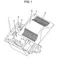
- FIG. 1is a perspective view of configuration of ventilator in a preferred embodiment of the invention.
- FIG. 2is a schematic wiring diagram of configuration of the ventilator.
- FIG. 3is a time chart of automatic operation of the ventilator.
- FIG. 4is a plan view of installation site of the ventilator.
- FIG. 5is a flowchart of automatic operation of the ventilator.
- FIG. 6is a wiring diagram of a conventional ventilator.
- FIG. 7is a time chart of automatic operation of the conventional ventilator.
- FIG. 1 to FIG. 5A preferred embodiment of the invention is described below while referring to FIG. 1 to FIG. 5 .
- the ventilator of the inventioncomprises a ventilator main body 1 , an exhaust fan motor 2 for exhausting room air by force, and a human sensor 4 for detecting the presence of human body. It further comprises a control unit 6 for controlling the fan motor 2 by receiving a signal from the human sensor 4 , and a flow rate adjusting unit 5 for adjusting the ventilation flow rate by the exhaust fan motor 2 .
- the control unit 6when detecting a signal from the human sensor 4 , operates the exhaust fan motor 2 for a specified time at fixed flow rate. While not detecting signal from the human sensor 4 , it operates the exhaust fan motor 2 all the time at ventilated flow rate adjusted by the flow rate adjusting unit 5 . During this ordinary operation, the flow rate may be adjusted by the flow rate adjusting unit 5 either steplessly or in multiple steps at small intervals.
- steplesslyit means to set the flow rate freely in a range of upper limit and lower limit of specified flow rate.
- multiple stepsit means to select the specified flow rate in plural stages in a range of upper limit and lower limit of specified flow rate.
- the ventilator main body 1 shown in FIG. 1 and FIG. 2is built in the ceiling of, for example, bathroom or toilet, and its discharge port (not shown) is disposed so as to communicate with outdoors through a duct (not shown).
- the exhaust fan motor 2is incorporated together with the control unit 6 for feeding power and controlling the exhaust fan motor 2 .
- a suction louver 3 provided at a suction port communicating with the discharge port trough the fan, the human sensor 4 installed in the suction louver 3 , and the flow rate adjusting unit 5 for adjusting the flow rate of the exhaust fan motor 2 from 100% to 30%are disposed at positions opposite from beneath the suction louver 3 .
- a wall switch 7for selecting either automatic operation or continuous operation, not capable of cutting off the power, is built in the room wall.
- a power supply wire 75is connected to the wall switch 7 , but power switch is not provided in the wall switch 7 , and it includes a selector 7 a consisting of automatic operation mode operating unit 72 for automatically changing the flow rate by the human sensor 4 , and a continuous operation mode operating unit 74 for feeding power continuously to the exhaust fan motor 2 by force at specified flow rate.
- a power switch 10 ais provided in the ventilator main body 1 for turning on or off the power supply, or may be provided in the wall switch 7 for turning on or off the power supply between the power supply wire 75 and the selector 7 a , so that it cannot be operated easily from outside of the room in which the ventilator main body is installed.
- the flow rate adjusting unit 5sets the flow rate in two modes, that is, flow rate A of maximum flow rate of exhaust fan motor 2 , and flow rate B adjusted in flow rate steplessly or in multiple steps at small intervals.
- the flow rateis set by adjusting knob, not shown, provided in the flow rate adjusting unit 5 .
- a detection defining unit 8is provided for cutting off the detection range of human sensor 4 in a specific direction only.
- the suction louver 3is disposed rotatably in the ventilator main body 1 .
- the detection defining unit 8is projected to the lower side of the suction louver 3 , and cuts off part of infrared ray or signal entering the human sensor 4 .
- the human sensor 4is formed on the surface of the suction louver 3 , at an end remote from the forming position of the detection defining unit 8 .
- the control unit 6has an arithmetic function of calculating the cumulative time T of the total time of detection of presence of human body.
- the control unit 6also has a function of storing preset time T 1 for judging either use of toilet or use of bathroom, and first delay time t 1 and second delay time t 2 for delay operation of exhaust fan motor 2 after the user leaves the toilet or bathroom.
- the preset time T 1is set as the threshold for judging the toilet time and bathing time. According to statistic data of actual time of use, the preset time T 1 is set at, for example, 5 minutes.
- the second delay time t 2is the time obtained from the experiment of measuring the time required when the moisture is reduced from 100% dew condensation state right after using the bathroom to about 90% by ventilation, and it is set at 2 hours in the preferred embodiment.
- the control unit 6reads the signal from the human sensor 4 , and judges the presence of human body.
- FIG. 3is a chart of automatic operation of the ventilator of the invention.
- the axis of ordinatesshows the flow rate of ventilator and the detection state by the human sensor 4
- the axis of abscissasdenotes the operation time of the ventilator and the detection time by the human sensor 4 .
- the control unit 6operates at flow rate B adjusted by the flow rate adjusting unit 5 as the optimum flow rate between 30% and 100%.
- the prefixed flow rate A100%
- human detection operationstarts.
- delay operationis conducted at flow rate A for the duration of t 1 or t 2 .
- FIG. 4is a plan view of bathroom and toilet at installation site of the ventilator of the invention.
- the ventilator main body 1is built in the ceiling of toilet 42 and bathroom 44 .
- the ventilator main body 1includes the detection defining unit 8 and human sensor 4 .
- the detection defining sensor 8is installed at a position where the detection range of human sensor 4 covers a relatively wide range including the bathroom 44 , but not reaching as far as the toilet 42 . That is, the detection range is the shaded area in the drawing.
- the reason of installation as shown in FIG. 4is to distinguish the toilet using case and the bathroom using case so as to detect the state correctly.
- the flow rateis controlled and the delay operation time is adjusted properly, and ventilation can be operated properly depending on the status of use, such as exhaust of room odor when using the toilet or room moisture when using the bathroom.
- the control unit 6counts the time when the user enters the room, and easily judges whether the bathroom is used or not. It is judged that the bathroom is used when the human detection signal is relatively long, and that the toilet is used when it is as short as several minutes.
- control unit 6can also judge the status of use by measuring the human presence time by the human sensor 4 .
- FIG. 5is a flowchart of automatic operation of the ventilator of the invention. Referring to FIG. 5 , the specific operation until the control unit 6 determines the flow rate by the human sensor 4 is explained below.
- the human sensor 4detects for human presence.
- human presenceis not detected (No at step 1 )
- the operationis conducted at flow rate B selected as ordinary ventilation flow rate.
- the signal detecting human presence by the human sensor 4is fed into the control unit 6 , and the process goes to step 2 .
- the control unit 6counts the human presence time in the toilet or bathroom, and determines the cumulative time T. Judging if the cumulative time T is over, for example, 5 minutes or not, when the cumulative time T is less than 5 minutes, for example, it is judged that the toilet is used. While the user is present in the room, the operation continues at fixed flow rate A. At this time, when the flow rate A is set at the maximum flow rate, a rapid ventilating effect is obtained.
- step 2if the user stays in the room for more than 5 minutes, the process goes to step 4 .
- step 4the control unit 6 judges the use of bathroom, and changes over to flow rate B adjusted as ordinary ventilation flow rate until the user leaves the room in order to lessen the feel of cold draft (No at step 4 ).
- cold draftis feeling of uncomfortable coldness by the user in the bathroom due to invading air by ventilation or air stream caused by ventilation.
- the ventilatoris built in the ceiling of the room, but the same action and effect are obtained in the ventilator of wall mount type.
- the preset time T 1is set at 5 minutes, t 1 at 15 minutes, and t 2 at 2 hours.
- the timemay be set appropriately depending on the bathing time, space ventilation time, and ventilation time required to lower the moisture in consideration of the building materials.
- the control unit 6operates the exhaust fan motor 2 for specified time at fixed flow rate when receiving detection signal from the human sensor 4 .
- the exhaust fan motor 2is operated usually at ventilation flow rate adjusted by the flow rate adjusting unit 5 . Since the ventilation flow rate during ordinary operation can be adjusted by the flow rate adjusting unit 5 steplessly or in multiple steps at small intervals, an appropriate ventilation flow rate can be selected depending on the environment of use, and efficient ventilation is possible all the time.
- the ventilator capable of purifying and ventilating the room air temporarilyis also presented.
- the flow rate in ordinary ventilationcan be set at optimum state suited to the condition of use.
- the wall switch 7does not have power switch, but includes a selector for selecting between automatic operation mode for automatically changing the ventilation flow rate by detection of the human sensor 4 , and continuous operation mode for operating the exhaust fan motor 2 continuously by force at specified ventilation flow rate. Accordingly, the user can select either operation mode, and even in the environment of use where the user selects the continuous operation mode more often than the automatic operation mode, the ventilation is not interrupted, and the ventilator operating ordinary ventilation by priority can be presented.
- the human sensor 4is disposed oppositely to the suction louver 3 provided at the suction port of the ventilator installed in one space including the bathroom and toilet, and the detection defining unit 8 for defining the detection range of the human sensor 4 is provided. Accordingly, the non-detecting position of human sensor 4 can be easily set in the room, and the ventilator capable of selecting control of ventilation operation suited to the environment of use can be presented.
- the ventilatorallowing the user to set the human sensor easily in a desired detecting range can be presented.
- the control unit 6when receiving a signal from the human sensor 4 , measures the human presence time, and varies the operation time of delay ventilation after the user leaves on the basis of the cumulative time, so that delay operation of appropriate ventilation depending on the status of use of toilet or bathroom is realized.
- the control unit 6when receiving a signal from the human sensor 4 , measures the human presence time, and controls the ventilation flow rate in the human presence state on the basis of the cumulative time, thereby preventing excessive ventilation state or insufficient ventilation state.
- the control unit 6when receiving a signal from the human sensor 4 , measures the human presence time, and controls the ventilation flow rate during ventilation delay operation after the user leaves on the basis of the cumulative time, so that delay flow rate of optimum ventilation is realized.
- the ventilator of the inventioncan adjust the ventilation flow rate in ordinary ventilation operation appropriately.
- operationis conducted at appropriate flow rate and for an appropriate time depending on the status of use of toilet or bathroom, and while saving waste of power and ventilating by saving energy, operation is done at necessary ventilation flow rate, and it is useful when installed in a space people enter or leave frequently such as dining room or living room, not limited to toilet or bathroom, and its industrial applicability is very high.
Landscapes
- Engineering & Computer Science (AREA)
- Chemical & Material Sciences (AREA)
- Combustion & Propulsion (AREA)
- Mechanical Engineering (AREA)
- General Engineering & Computer Science (AREA)
- Physics & Mathematics (AREA)
- Fluid Mechanics (AREA)
- Fuzzy Systems (AREA)
- Mathematical Physics (AREA)
- Signal Processing (AREA)
- Air Conditioning Control Device (AREA)
- Ventilation (AREA)
Abstract
Description
Claims (6)
Priority Applications (1)
| Application Number | Priority Date | Filing Date | Title |
|---|---|---|---|
| US11/242,128US7455583B2 (en) | 2005-10-04 | 2005-10-04 | Ventilator including a control unit and human sensor |
Applications Claiming Priority (1)
| Application Number | Priority Date | Filing Date | Title |
|---|---|---|---|
| US11/242,128US7455583B2 (en) | 2005-10-04 | 2005-10-04 | Ventilator including a control unit and human sensor |
Publications (2)
| Publication Number | Publication Date |
|---|---|
| US20070074725A1 US20070074725A1 (en) | 2007-04-05 |
| US7455583B2true US7455583B2 (en) | 2008-11-25 |
Family
ID=37900736
Family Applications (1)
| Application Number | Title | Priority Date | Filing Date |
|---|---|---|---|
| US11/242,128Active2026-03-23US7455583B2 (en) | 2005-10-04 | 2005-10-04 | Ventilator including a control unit and human sensor |
Country Status (1)
| Country | Link |
|---|---|
| US (1) | US7455583B2 (en) |
Cited By (37)
| Publication number | Priority date | Publication date | Assignee | Title |
|---|---|---|---|---|
| US20090108082A1 (en)* | 2007-10-31 | 2009-04-30 | Richard Goldmann | Programmatic climate control of an exercise environment |
| US20100197216A1 (en)* | 2007-04-24 | 2010-08-05 | Panasonic Corporation | Ventilator with illuminating unit and human sensor |
| US20120052792A1 (en)* | 2010-08-31 | 2012-03-01 | Broan-Nutone Llc. | Ventilation Unit Calibration Apparatus, System and Method |
| US8267085B2 (en) | 2009-03-20 | 2012-09-18 | Nellcor Puritan Bennett Llc | Leak-compensated proportional assist ventilation |
| US8272379B2 (en) | 2008-03-31 | 2012-09-25 | Nellcor Puritan Bennett, Llc | Leak-compensated flow triggering and cycling in medical ventilators |
| US8418691B2 (en) | 2009-03-20 | 2013-04-16 | Covidien Lp | Leak-compensated pressure regulated volume control ventilation |
| US8424521B2 (en) | 2009-02-27 | 2013-04-23 | Covidien Lp | Leak-compensated respiratory mechanics estimation in medical ventilators |
| US8457706B2 (en) | 2008-05-16 | 2013-06-04 | Covidien Lp | Estimation of a physiological parameter using a neural network |
| US8551006B2 (en) | 2008-09-17 | 2013-10-08 | Covidien Lp | Method for determining hemodynamic effects |
| US8554298B2 (en) | 2010-09-21 | 2013-10-08 | Cividien LP | Medical ventilator with integrated oximeter data |
| US8676285B2 (en) | 2010-07-28 | 2014-03-18 | Covidien Lp | Methods for validating patient identity |
| US8746248B2 (en) | 2008-03-31 | 2014-06-10 | Covidien Lp | Determination of patient circuit disconnect in leak-compensated ventilatory support |
| US20140190679A1 (en)* | 2013-01-07 | 2014-07-10 | Honeywell International Inc. | Control assembly |
| US8789529B2 (en) | 2009-08-20 | 2014-07-29 | Covidien Lp | Method for ventilation |
| US20150024675A1 (en)* | 2007-03-07 | 2015-01-22 | Sine Kon Hu | Airflow Boosting Assembly for a Forced Air Circulation and Delivery System |
| US9089657B2 (en) | 2011-10-31 | 2015-07-28 | Covidien Lp | Methods and systems for gating user initiated increases in oxygen concentration during ventilation |
| USD745652S1 (en) | 2014-01-28 | 2015-12-15 | Homewerks Worldwide, LLC | Fan grille |
| USD752199S1 (en) | 2014-09-22 | 2016-03-22 | Homewerks Worldwide, LLC | Bath fan with speaker |
| USD752202S1 (en) | 2013-08-08 | 2016-03-22 | Homewerks Worldwide, LLC | Fan grille |
| US9344787B2 (en) | 2012-12-22 | 2016-05-17 | Homewerks Worldwide, LLC | Audio equipped fan |
| US9398357B2 (en) | 2012-12-22 | 2016-07-19 | Homewerks Worldwide, LLC | Audio equipped fan |
| US9609407B2 (en) | 2012-12-22 | 2017-03-28 | Homewerks Worldwide, LLC | Method of manufacturing an audio equipped fan assembly |
| US9649458B2 (en) | 2008-09-30 | 2017-05-16 | Covidien Lp | Breathing assistance system with multiple pressure sensors |
| US9675771B2 (en) | 2013-10-18 | 2017-06-13 | Covidien Lp | Methods and systems for leak estimation |
| USD808001S1 (en) | 2016-03-14 | 2018-01-16 | Homewerks Worldwide, LLC | Square fan grille |
| US9950129B2 (en) | 2014-10-27 | 2018-04-24 | Covidien Lp | Ventilation triggering using change-point detection |
| US9993604B2 (en) | 2012-04-27 | 2018-06-12 | Covidien Lp | Methods and systems for an optimized proportional assist ventilation |
| US20180180320A1 (en)* | 2016-12-28 | 2018-06-28 | Panasonic Intellectual Property Management Co., Ltd. | Ventilation grille and ventilation fan |
| US10207069B2 (en) | 2008-03-31 | 2019-02-19 | Covidien Lp | System and method for determining ventilator leakage during stable periods within a breath |
| US10362967B2 (en) | 2012-07-09 | 2019-07-30 | Covidien Lp | Systems and methods for missed breath detection and indication |
| USD932612S1 (en) | 2019-11-26 | 2021-10-05 | Homewerks Worldwide, LLC | Fan grille |
| USD932611S1 (en) | 2019-06-24 | 2021-10-05 | Homewerks Worldwide, LLC | Fan grille |
| USD933194S1 (en) | 2019-06-24 | 2021-10-12 | Homewerks Worldwide, LLC | Fan grille |
| USD933195S1 (en) | 2019-11-26 | 2021-10-12 | Homewerks Worldwide, LLC | Fan grille |
| USD933809S1 (en) | 2019-11-26 | 2021-10-19 | Homewerks Worldwide, LLC | Fan grille |
| USD948025S1 (en) | 2019-11-26 | 2022-04-05 | Homewerks Worldwide, LLC | Fan grille |
| US11913460B2 (en) | 2020-03-20 | 2024-02-27 | Greenheck Fan Corporation | Exhaust fan |
Families Citing this family (7)
| Publication number | Priority date | Publication date | Assignee | Title |
|---|---|---|---|---|
| CN101576095B (en)* | 2008-05-05 | 2010-12-15 | 广东松下环境系统有限公司 | Air exchange fan with heater |
| JP5268603B2 (en)* | 2008-12-05 | 2013-08-21 | 三洋電機株式会社 | Sensor mounting structure and projector apparatus including the same |
| FR2975610A1 (en)* | 2011-05-26 | 2012-11-30 | Sylvie Criou | FUME EXTRACTION UNIT ADAPTABLE TO ALL TYPES OF CONFINED VOLUMES |
| JP1526824S (en)* | 2014-09-05 | 2015-06-22 | ||
| CN111895558B (en)* | 2020-08-11 | 2021-12-10 | 苏州贝佳新能源科技有限公司 | Air conditioner cooling system based on building body structure |
| JP7731035B2 (en)* | 2021-12-24 | 2025-08-29 | パナソニックIpマネジメント株式会社 | ventilation equipment |
| CN115793489A (en)* | 2022-11-30 | 2023-03-14 | 青岛海尔空调器有限总公司 | Smart home system and control method thereof |
Citations (13)
| Publication number | Priority date | Publication date | Assignee | Title |
|---|---|---|---|---|
| US2619021A (en)* | 1949-08-04 | 1952-11-25 | Ilg Electric Ventilating Compa | Ventilator fan mounting |
| JPS61213542A (en)* | 1985-03-20 | 1986-09-22 | Matsushita Seiko Co Ltd | Control device for ventilation fans in toilets |
| JPS62242743A (en)* | 1986-04-15 | 1987-10-23 | Matsushita Electric Ind Co Ltd | Control device for discharging air |
| JPS63129232A (en)* | 1986-11-19 | 1988-06-01 | Matsushita Seiko Co Ltd | Controller for ventilating fan of toilet |
| JPH0275798A (en)* | 1988-09-09 | 1990-03-15 | Sanyo Electric Co Ltd | Blower device |
| JPH02251036A (en)* | 1989-03-22 | 1990-10-08 | Matsushita Seiko Co Ltd | Automatic operating device for ventilating fan for toilet room |
| US5309146A (en)* | 1988-05-03 | 1994-05-03 | Electronic Environmental Controls Inc. | Room occupancy indicator means and method |
| JPH06249477A (en)* | 1993-02-25 | 1994-09-06 | Sekisui Chem Co Ltd | Lighting and ventilation control device for toilet |
| JPH0979623A (en) | 1995-09-20 | 1997-03-28 | Matsushita Seiko Co Ltd | Ventilating fan |
| US5862981A (en)* | 1997-08-04 | 1999-01-26 | Yiue Feng Enterprise Co., Ltd. | Ventilation control device for a bathroom |
| US5910045A (en)* | 1995-09-07 | 1999-06-08 | Daikin Industries, Ltd. | Air discharge unit for underfloor air conditioning and underfloor air conditioning system using same |
| US6079626A (en)* | 1996-01-16 | 2000-06-27 | Hartman; Thomas B. | Terminal unit with active diffuser |
| US20030211820A1 (en)* | 2002-05-09 | 2003-11-13 | Yoshinori Tsuji | Car defroster |
- 2005
- 2005-10-04USUS11/242,128patent/US7455583B2/enactiveActive
Patent Citations (13)
| Publication number | Priority date | Publication date | Assignee | Title |
|---|---|---|---|---|
| US2619021A (en)* | 1949-08-04 | 1952-11-25 | Ilg Electric Ventilating Compa | Ventilator fan mounting |
| JPS61213542A (en)* | 1985-03-20 | 1986-09-22 | Matsushita Seiko Co Ltd | Control device for ventilation fans in toilets |
| JPS62242743A (en)* | 1986-04-15 | 1987-10-23 | Matsushita Electric Ind Co Ltd | Control device for discharging air |
| JPS63129232A (en)* | 1986-11-19 | 1988-06-01 | Matsushita Seiko Co Ltd | Controller for ventilating fan of toilet |
| US5309146A (en)* | 1988-05-03 | 1994-05-03 | Electronic Environmental Controls Inc. | Room occupancy indicator means and method |
| JPH0275798A (en)* | 1988-09-09 | 1990-03-15 | Sanyo Electric Co Ltd | Blower device |
| JPH02251036A (en)* | 1989-03-22 | 1990-10-08 | Matsushita Seiko Co Ltd | Automatic operating device for ventilating fan for toilet room |
| JPH06249477A (en)* | 1993-02-25 | 1994-09-06 | Sekisui Chem Co Ltd | Lighting and ventilation control device for toilet |
| US5910045A (en)* | 1995-09-07 | 1999-06-08 | Daikin Industries, Ltd. | Air discharge unit for underfloor air conditioning and underfloor air conditioning system using same |
| JPH0979623A (en) | 1995-09-20 | 1997-03-28 | Matsushita Seiko Co Ltd | Ventilating fan |
| US6079626A (en)* | 1996-01-16 | 2000-06-27 | Hartman; Thomas B. | Terminal unit with active diffuser |
| US5862981A (en)* | 1997-08-04 | 1999-01-26 | Yiue Feng Enterprise Co., Ltd. | Ventilation control device for a bathroom |
| US20030211820A1 (en)* | 2002-05-09 | 2003-11-13 | Yoshinori Tsuji | Car defroster |
Non-Patent Citations (1)
| Title |
|---|
| Attached English translation of Japanese Patent No. 09-079623 (machine-generated).* |
Cited By (55)
| Publication number | Priority date | Publication date | Assignee | Title |
|---|---|---|---|---|
| US20150024675A1 (en)* | 2007-03-07 | 2015-01-22 | Sine Kon Hu | Airflow Boosting Assembly for a Forced Air Circulation and Delivery System |
| US10132514B2 (en)* | 2007-03-07 | 2018-11-20 | Sine Kon Hu | Airflow boosting assembly for a forced air circulation and delivery system |
| US20100197216A1 (en)* | 2007-04-24 | 2010-08-05 | Panasonic Corporation | Ventilator with illuminating unit and human sensor |
| US20090108082A1 (en)* | 2007-10-31 | 2009-04-30 | Richard Goldmann | Programmatic climate control of an exercise environment |
| US8272380B2 (en) | 2008-03-31 | 2012-09-25 | Nellcor Puritan Bennett, Llc | Leak-compensated pressure triggering in medical ventilators |
| US11027080B2 (en) | 2008-03-31 | 2021-06-08 | Covidien Lp | System and method for determining ventilator leakage during stable periods within a breath |
| US9421338B2 (en) | 2008-03-31 | 2016-08-23 | Covidien Lp | Ventilator leak compensation |
| US8746248B2 (en) | 2008-03-31 | 2014-06-10 | Covidien Lp | Determination of patient circuit disconnect in leak-compensated ventilatory support |
| US8434480B2 (en) | 2008-03-31 | 2013-05-07 | Covidien Lp | Ventilator leak compensation |
| US8272379B2 (en) | 2008-03-31 | 2012-09-25 | Nellcor Puritan Bennett, Llc | Leak-compensated flow triggering and cycling in medical ventilators |
| US10207069B2 (en) | 2008-03-31 | 2019-02-19 | Covidien Lp | System and method for determining ventilator leakage during stable periods within a breath |
| US8457706B2 (en) | 2008-05-16 | 2013-06-04 | Covidien Lp | Estimation of a physiological parameter using a neural network |
| US8551006B2 (en) | 2008-09-17 | 2013-10-08 | Covidien Lp | Method for determining hemodynamic effects |
| US9414769B2 (en) | 2008-09-17 | 2016-08-16 | Covidien Lp | Method for determining hemodynamic effects |
| US9649458B2 (en) | 2008-09-30 | 2017-05-16 | Covidien Lp | Breathing assistance system with multiple pressure sensors |
| US8424521B2 (en) | 2009-02-27 | 2013-04-23 | Covidien Lp | Leak-compensated respiratory mechanics estimation in medical ventilators |
| US8448641B2 (en) | 2009-03-20 | 2013-05-28 | Covidien Lp | Leak-compensated proportional assist ventilation |
| US8267085B2 (en) | 2009-03-20 | 2012-09-18 | Nellcor Puritan Bennett Llc | Leak-compensated proportional assist ventilation |
| US8973577B2 (en) | 2009-03-20 | 2015-03-10 | Covidien Lp | Leak-compensated pressure regulated volume control ventilation |
| US8978650B2 (en) | 2009-03-20 | 2015-03-17 | Covidien Lp | Leak-compensated proportional assist ventilation |
| US8418691B2 (en) | 2009-03-20 | 2013-04-16 | Covidien Lp | Leak-compensated pressure regulated volume control ventilation |
| US8789529B2 (en) | 2009-08-20 | 2014-07-29 | Covidien Lp | Method for ventilation |
| US8676285B2 (en) | 2010-07-28 | 2014-03-18 | Covidien Lp | Methods for validating patient identity |
| US9638432B2 (en)* | 2010-08-31 | 2017-05-02 | Broan-Nutone Llc | Ventilation unit calibration apparatus, system and method |
| US20120052792A1 (en)* | 2010-08-31 | 2012-03-01 | Broan-Nutone Llc. | Ventilation Unit Calibration Apparatus, System and Method |
| US8554298B2 (en) | 2010-09-21 | 2013-10-08 | Cividien LP | Medical ventilator with integrated oximeter data |
| US9089657B2 (en) | 2011-10-31 | 2015-07-28 | Covidien Lp | Methods and systems for gating user initiated increases in oxygen concentration during ventilation |
| US9993604B2 (en) | 2012-04-27 | 2018-06-12 | Covidien Lp | Methods and systems for an optimized proportional assist ventilation |
| US10806879B2 (en) | 2012-04-27 | 2020-10-20 | Covidien Lp | Methods and systems for an optimized proportional assist ventilation |
| US11642042B2 (en) | 2012-07-09 | 2023-05-09 | Covidien Lp | Systems and methods for missed breath detection and indication |
| US10362967B2 (en) | 2012-07-09 | 2019-07-30 | Covidien Lp | Systems and methods for missed breath detection and indication |
| US9609407B2 (en) | 2012-12-22 | 2017-03-28 | Homewerks Worldwide, LLC | Method of manufacturing an audio equipped fan assembly |
| US9398357B2 (en) | 2012-12-22 | 2016-07-19 | Homewerks Worldwide, LLC | Audio equipped fan |
| US9344787B2 (en) | 2012-12-22 | 2016-05-17 | Homewerks Worldwide, LLC | Audio equipped fan |
| US10181708B2 (en)* | 2013-01-07 | 2019-01-15 | Honeywell International Inc. | Control Assembly |
| US20140190679A1 (en)* | 2013-01-07 | 2014-07-10 | Honeywell International Inc. | Control assembly |
| USD752202S1 (en) | 2013-08-08 | 2016-03-22 | Homewerks Worldwide, LLC | Fan grille |
| US10207068B2 (en) | 2013-10-18 | 2019-02-19 | Covidien Lp | Methods and systems for leak estimation |
| US11235114B2 (en) | 2013-10-18 | 2022-02-01 | Covidien Lp | Methods and systems for leak estimation |
| US9675771B2 (en) | 2013-10-18 | 2017-06-13 | Covidien Lp | Methods and systems for leak estimation |
| USD745652S1 (en) | 2014-01-28 | 2015-12-15 | Homewerks Worldwide, LLC | Fan grille |
| USD752199S1 (en) | 2014-09-22 | 2016-03-22 | Homewerks Worldwide, LLC | Bath fan with speaker |
| US9950129B2 (en) | 2014-10-27 | 2018-04-24 | Covidien Lp | Ventilation triggering using change-point detection |
| US11712174B2 (en) | 2014-10-27 | 2023-08-01 | Covidien Lp | Ventilation triggering |
| US10940281B2 (en) | 2014-10-27 | 2021-03-09 | Covidien Lp | Ventilation triggering |
| USD808001S1 (en) | 2016-03-14 | 2018-01-16 | Homewerks Worldwide, LLC | Square fan grille |
| US10837662B2 (en)* | 2016-12-28 | 2020-11-17 | Panasonic Intellectual Property Management Co., Ltd. | Ventilation grille and ventilation fan |
| US20180180320A1 (en)* | 2016-12-28 | 2018-06-28 | Panasonic Intellectual Property Management Co., Ltd. | Ventilation grille and ventilation fan |
| USD933194S1 (en) | 2019-06-24 | 2021-10-12 | Homewerks Worldwide, LLC | Fan grille |
| USD932611S1 (en) | 2019-06-24 | 2021-10-05 | Homewerks Worldwide, LLC | Fan grille |
| USD933195S1 (en) | 2019-11-26 | 2021-10-12 | Homewerks Worldwide, LLC | Fan grille |
| USD933809S1 (en) | 2019-11-26 | 2021-10-19 | Homewerks Worldwide, LLC | Fan grille |
| USD948025S1 (en) | 2019-11-26 | 2022-04-05 | Homewerks Worldwide, LLC | Fan grille |
| USD932612S1 (en) | 2019-11-26 | 2021-10-05 | Homewerks Worldwide, LLC | Fan grille |
| US11913460B2 (en) | 2020-03-20 | 2024-02-27 | Greenheck Fan Corporation | Exhaust fan |
Also Published As
| Publication number | Publication date |
|---|---|
| US20070074725A1 (en) | 2007-04-05 |
Similar Documents
| Publication | Publication Date | Title |
|---|---|---|
| US7455583B2 (en) | Ventilator including a control unit and human sensor | |
| JP6987264B2 (en) | Ventilation device and ventilation control method | |
| US9933182B2 (en) | System for optimising an environmental parameter of an enclosed space | |
| JP4125354B1 (en) | Air conditioner | |
| JP6282031B2 (en) | Ventilator for air conditioning | |
| JP4434998B2 (en) | Indoor temperature control system | |
| JP4432467B2 (en) | Ventilation control device | |
| JP2010096382A (en) | Ventilation device | |
| JP2007212026A (en) | Residential ventilation system | |
| JP7378338B2 (en) | ventilation system | |
| JP3543053B2 (en) | Residential ventilation equipment | |
| JP4352905B2 (en) | Ventilation equipment | |
| JP2005098573A (en) | Ventilation equipment | |
| JP2002257390A (en) | Ventilation system for building and ventilation method therefor | |
| JP6415876B2 (en) | Room temperature control system | |
| JP5072641B2 (en) | Ventilation equipment | |
| JP2006105473A (en) | Ventilation system | |
| JP3132958B2 (en) | Residential ventilation system | |
| JP2007003085A (en) | Ventilation equipment | |
| KR101153724B1 (en) | Ventilation fan control system for buildings | |
| JP7462594B2 (en) | Ventilation system | |
| JPH06185768A (en) | Ventilator | |
| JP2005016936A (en) | Natural ventilation system for detached house and control method thereof | |
| JP7599381B2 (en) | Ventilation system | |
| JP3375869B2 (en) | Control device for constant ventilation device |
Legal Events
| Date | Code | Title | Description |
|---|---|---|---|
| AS | Assignment | Owner name:MATSUSHITA ELECTRIC INDUSTRIAL CO., LTD., JAPAN Free format text:ASSIGNMENT OF ASSIGNORS INTEREST;ASSIGNOR:TAYA, HITOSHI;REEL/FRAME:017032/0466 Effective date:20051019 | |
| STCF | Information on status: patent grant | Free format text:PATENTED CASE | |
| AS | Assignment | Owner name:PANASONIC CORPORATION, JAPAN Free format text:CHANGE OF NAME;ASSIGNOR:MATSUSHITA ELECTRIC INDUSTRIAL CO., LTD.;REEL/FRAME:021897/0689 Effective date:20081001 Owner name:PANASONIC CORPORATION,JAPAN Free format text:CHANGE OF NAME;ASSIGNOR:MATSUSHITA ELECTRIC INDUSTRIAL CO., LTD.;REEL/FRAME:021897/0689 Effective date:20081001 | |
| FEPP | Fee payment procedure | Free format text:PAYOR NUMBER ASSIGNED (ORIGINAL EVENT CODE: ASPN); ENTITY STATUS OF PATENT OWNER: LARGE ENTITY | |
| FPAY | Fee payment | Year of fee payment:4 | |
| FEPP | Fee payment procedure | Free format text:PAYOR NUMBER ASSIGNED (ORIGINAL EVENT CODE: ASPN); ENTITY STATUS OF PATENT OWNER: LARGE ENTITY Free format text:PAYER NUMBER DE-ASSIGNED (ORIGINAL EVENT CODE: RMPN); ENTITY STATUS OF PATENT OWNER: LARGE ENTITY | |
| FPAY | Fee payment | Year of fee payment:8 | |
| MAFP | Maintenance fee payment | Free format text:PAYMENT OF MAINTENANCE FEE, 12TH YEAR, LARGE ENTITY (ORIGINAL EVENT CODE: M1553); ENTITY STATUS OF PATENT OWNER: LARGE ENTITY Year of fee payment:12 |