US7455370B2 - Brake pipe control system with remote radio car - Google Patents
Brake pipe control system with remote radio carDownload PDFInfo
- Publication number
- US7455370B2 US7455370B2US11/288,316US28831605AUS7455370B2US 7455370 B2US7455370 B2US 7455370B2US 28831605 AUS28831605 AUS 28831605AUS 7455370 B2US7455370 B2US 7455370B2
- Authority
- US
- United States
- Prior art keywords
- brake pipe
- car
- controller
- train
- radio
- Prior art date
- Legal status (The legal status is an assumption and is not a legal conclusion. Google has not performed a legal analysis and makes no representation as to the accuracy of the status listed.)
- Expired - Fee Related, expires
Links
- 230000003137locomotive effectEffects0.000claimsdescription17
- 230000006854communicationEffects0.000abstractdescription18
- 238000004891communicationMethods0.000abstractdescription18
- 238000007459endoscopic retrograde cholangiopancreatographyMethods0.000description7
- 239000003550markerSubstances0.000description2
- 230000007175bidirectional communicationEffects0.000description1
- 230000005540biological transmissionEffects0.000description1
- 230000000694effectsEffects0.000description1
- 239000012530fluidSubstances0.000description1
- 238000012986modificationMethods0.000description1
- 230000004048modificationEffects0.000description1
- 238000011084recoveryMethods0.000description1
Images


Classifications
- B—PERFORMING OPERATIONS; TRANSPORTING
- B60—VEHICLES IN GENERAL
- B60T—VEHICLE BRAKE CONTROL SYSTEMS OR PARTS THEREOF; BRAKE CONTROL SYSTEMS OR PARTS THEREOF, IN GENERAL; ARRANGEMENT OF BRAKING ELEMENTS ON VEHICLES IN GENERAL; PORTABLE DEVICES FOR PREVENTING UNWANTED MOVEMENT OF VEHICLES; VEHICLE MODIFICATIONS TO FACILITATE COOLING OF BRAKES
- B60T17/00—Component parts, details, or accessories of power brake systems not covered by groups B60T8/00, B60T13/00 or B60T15/00, or presenting other characteristic features
- B60T17/18—Safety devices; Monitoring
- B60T17/22—Devices for monitoring or checking brake systems; Signal devices
- B60T17/228—Devices for monitoring or checking brake systems; Signal devices for railway vehicles
- B—PERFORMING OPERATIONS; TRANSPORTING
- B60—VEHICLES IN GENERAL
- B60T—VEHICLE BRAKE CONTROL SYSTEMS OR PARTS THEREOF; BRAKE CONTROL SYSTEMS OR PARTS THEREOF, IN GENERAL; ARRANGEMENT OF BRAKING ELEMENTS ON VEHICLES IN GENERAL; PORTABLE DEVICES FOR PREVENTING UNWANTED MOVEMENT OF VEHICLES; VEHICLE MODIFICATIONS TO FACILITATE COOLING OF BRAKES
- B60T7/00—Brake-action initiating means
- B60T7/12—Brake-action initiating means for automatic initiation; for initiation not subject to will of driver or passenger
- B60T7/16—Brake-action initiating means for automatic initiation; for initiation not subject to will of driver or passenger operated by remote control, i.e. initiating means not mounted on vehicle
Definitions
- the present systemrelates generally to brake control systems and more specifically to a brake pipe control system from both ends of the train and possibly at a point in between.
- the control of a brake pipe of a train from ends of the trainis well known as illustrated by U.S. Pat. Nos. 4,013,323 and 4,056,286.
- This controlis produced by radio communication between the locomotive at the head-end and the caboose at the rear-end of the train.
- Radio control of two locomotiveconsists in a train with the remote consists being substantially in the middle of the train is illustrated in U.S. Pat. No. 3,380,399.
- the radio carreceives the signals from the master locomotive and operates to create locomotive control signals for the locomotives attached to the radio car.
- the radio caris not itself a locomotive.
- Radio communication between the head and mid-train and end of train unit or a multitude of carsis illustrated in U.S. Pat. No. 6,375,276 and U.S. Pat. No. 4,553,723.
- end of train unitsare provided and attached to a regular car which is the last car in the train and is in radio communication with the head of train unit.
- EOTend of train units
- a typical exampleis additionally shown in U.S. Pat. No. 6,126,247.
- the present disclosureis directed to a radio repeater or remote railroad car located within or at the end of the train that charges or exhausts the brake pipe in response to radio commands from the lead unit.
- the brake pipe control systemincludes a first controller at a first car at the lead end for controlling the brake pipe at the first car and transmitting, via a radio link, brake pipe control signals to a second controller in a remote car in the train.
- the second controllercontrols the brake pipe at the remote car in response to the brake pipe control signals from the first controller. If the second controller is on the last car and the last car does not include an independent end of train device, the second controller transmits brake pipe condition signals to the first controller.
- the first controllerestablished separate communication links with the second controller and the end of train device. If the second controller is not on the last car and the last car includes an end of train device, the first controller established separate communication links with the second controller and the end of train device.
- the remote or radio repeater carcharges or exhausts the brake pipe in response to commands received from the first or head car end or unit which is generally a locomotive. It also has the capability of charging or exhausting the brake pipe as well as means for brake pipe cutoff required for brake pipe leakage testing.
- the radio repeater carincludes a source of air pressure, a brake pipe controller and a radio module.
- the lead unitcommunicates with the radio repeater car in parallel to an end of train device EOT. If the radio repeater is the last car, the EOT device is mounted on the radio car. This parallel communication is secured by providing an end of car device at the lead unit. It senses the brake pipe conditions and transmits communication to the repeater car radio module.
- the remote repeater radio moduleis capable of parallel communication to an end of car device at the lead locomotive as well as the end of train control device unit at the lead locomotive.
- the repeater radio moduleis capable of communicating with a end of train control device through a single channel.
- FIG. 1is a schematic representation of a train including a first embodiment of the present brake pipe control system.
- FIG. 2is a schematic representation of a train including a second embodiment of the present brake pipe control system.
- FIG. 3is a schematic representation of a train including a third embodiment of the present brake pipe control system.
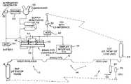
- FIG. 4is a schematic representation of a brake pipe controller in the radio repeater car according to the present brake pipe control system.
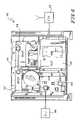
- FIG. 5is a fluid schematic representation of an equalization reservoir control portion of the FIG. 4 controller.
- FIGS. 1-3show a train with a head unit or locomotive 10 , a remote or radio repeater car 12 and a plurality of other cars 14 therebetween and interconnected by brake pipe 16 .
- the radio repeater car 12is at the end of the train, but it may be anywhere within the train.
- the lead unitis at the head end of the train and may be the first car in the train or in any case in the head end consist.
- the trainincludes an end of train device (EOT) 18 connected to the brake pipe at the last car.
- EOTend of train device
- the radio repeater car brake pipe control systemperforms the same function as the end of train device and therefore only requires a marker light 20 since it does not have the marker light that is integrated into the end of train device 18 .
- the lead locomotiveincludes a brake pipe a locomotive brake valve 22 with an input device 24 for the operator.
- Locomotive brake valve 22is a brake pipe controller which controls the pressure on the brake pipe 16 to transmit brake application and release signals on the brake pipe 16 .
- the lead unit 10also includes a communication link for the EOT device 18 .
- a communication devicefor example a cab display unit CDU 26 , communicates directly with EOT 18
- the CDU 26communicates with the radio repeater module 30 since an EOT 18 is not provided.
- An example of a CDUis model 6696 from Union Switch and Signal.
- a separate communication link from the lead unit 10 and the EOT 18is provided between the lead unit 10 and the radio repeater or remote car 12 .
- Thisis provided by an EOT device 28 at the lead unit.
- the EOT device 28 at the lead unit 10communicates with a cab interface unit CIU 32 , which may be the same as the CDU 26 at the lead or just a cab interface unit CIU, for example, a Union Switch & Signal model 6680. If it is a CIU, a separate display and interface or operator interface OIU 34 is provided as illustrated in FIG. 1 . If the CIU 32 is the same as the CDU 26 , it has a display and operator interface integral thereto, and therefore a separate display and interface 34 is then needed. This is illustrated in FIG. 2 as the generic radio module 30 .
- the repeater radio module 30is capable of communicating with a head of train device HOTD 29 .
- Thismay be, for example, a WABTEC Train LinkTM system. If such system is used, the additional EOT device 28 at the lead unit 10 , as shown in FIGS. 1 and 2 , would not be needed for communication to the radio repeater car 12 .
- the transmitter to an end of train devicecan only have a single identifier for the end of train device.
- the CDU 26would be set to an identifier for the EOT 18 different than the identifier that CIU 32 would bet set for the EOT device 28 .
- the repeater radio module 30would have the ID of an end of train device for communication with CDU 26 while the EOT 28 at the lead unit would have a different identifier for transmission with the radio module 30 .
- bidirectional communicationwould be conducted with the repeater radio module 30 having an end of train device identifier to be received by the transmitter 29 .
- the transmitter 29would have the equivalent of a train identifier with respect to the transmitter of the repeater radio module 30 .
- the EOTs 18 and 28 and the remote radio car 12 acting as an EOTshould be two-way communication devices with the “arming” feature for an emergency braking of the brake pipe by the EOTs.
- FIG. 1allows remote radio car 12 to be other than at the end of train device because two separate communication links are established between the lead unit 10 and the end of train device 18 and the remote radio car 12 .
- the remote radio car 12includes a brake pipe controller 40 .
- the brake pipe controller 40includes an equalization reservoir control portion ERCP 42 , a brake pipe control portion BPCP 44 , a power supply and control portion PSCP 46 and a relay control portion RCP 48 mounted to a manifold 49 .
- the brake pipe controller 40includes standard elements part of an electro-pneumatic locomotive brake system, for example CCB® Locomotive Brake Control Unit available from New York Air Brake Corporation and is illustrated in U.S. Pat. No. 6,036,284, which is incorporated herein by reference. Other electro-pneumatic locomotive brake systems may be used.
- the relay control portion RCP 48is effectively the input device equivalent to the electronic brake valve EBV in the CCB® in that it takes the radio received brake signals and provides them as inputs to the control portions.
- the remote radio car 12also includes an engine 50 , for example, diesel engine which drives an alternator/generator 52 to charge battery 54 .
- the engine 50also drives compressor 56 to fill supply reservoirs 58 for the brake pipe controller 40 .
- the brake pipe controller 40is responsive to inputs from the display interface OIU 34 and signals received via CIU 32 or other repeater radio module 30 to control pressure in the brake pipe 16 at its car. Signals are used to vary the value in the equalization reservoir to the desired brake value by ERCP 42 .
- the brake pipe control portion BPCP 44is responsive to the value in the equalization reservoir to control the value of the brake pipe 16 at its car. Measured values of brake pipe and equalization reservoir may also be transmitted from the remote radio car 12 back to the head end unit via 30 or 32 .
- the brake pipe controller 40is that in a CCB® controller. Reference is made to FIG. 10 of U.S. Pat. No. 6,036,284 for the details.
- the brake pipe control portion BPCP 44is responsive to the pressure and equalization reservoir controlled by the equalization regular control portion ERCP 42 and controls the brake pipe as a function of the pressure and equalization reservoir and the brake pipe pressure.
- the equalization reservoir control portion ERCP 42 as illustrated in FIG. 5is a modification of the equalization reservoir control portion ERCP 42 as shown in FIG. 18 of U.S. Pat. No. 6,036,284.
- the input 208 into the MVERis not the ER backup but is exhaust EX.
- the choke and check valve portion DE, DER, C 1 , CV 1 used to interconnect the main reservoir MR and the brake pipe BP 16is disabled by connecting the brake pipe port to exhaust EX, as is shown in portion 220 .
- the present structurehas an addition structure for pneumatic emergency and electronic control similar to portion 240 of the 16 interface portion illustrated in FIG. 22 of U.S. Pat. No. 6,036,284.
- the magnetic valve portion of the MVERwhich is the pilot line for the pneumatic portion, are connected via line 216 , choke C 2 and check valve CV 2 to the output of an emergency pilot valve PVSU.
- Pilot line 216 for emergency pilot valve PVSUis either closed or open via line 252 exhaust EX. If it is connected to exhaust it prevents the pilot pressure for the pilot valve portion of the MVER to build up. This results in the output 212 , which is connected to the equalization reservoir, to be connected to exhaust EX equalization reservoir.
- the pilot portion of the pilot valve PVSUis connected to the output of the double check valve DCV.
- One input on line 254is connected to the main reservoir.
- the other input on line 252is connected to the output of the magnetic valve MV 26 .
- MV 26is selectively controlled to connect line 252 to the main reservoir or MR to the exhaust EX.
- a pilot MV 26has been connected so it has no effect on the ultimate circuit.
- Equalization reservoir (ER) pressureis developed and controlled by the ‘APP & REL’ magnet valves in conjunction with feedback pressure from transducer ERT.
- the ER controlis connected through the pilot valve of magnet valve MVER to the ER Volume and thus the control port of the brake pipe relay within the BPCP 44 , as previously described.
- the MVER magnet valveis normally de-energized. This causes its pilot valve to be in the de-activated position as shown. In this position, the ER Volume is connected to atmosphere either preventing charging of brake pipe or exhausting ER Volume at a prescribed rate (chocked orifice normally set to service rate).
- the MVERIn order to electronically control ER Volume, the MVER must be energized and the pneumatic override must be satisfied.
- the MVERis driven directly by the intelligent controller of the ERCP 42 and is energized when the remote radio car is active and no fault or override condition is present.
- MR supplyWhen the MVER is energized, MR supply is ported to the pilot valve and through check valve CV 2 to the #10 port (blanked optional potential) and to pilot valve PVSU.
- the PVSUde-activated ports through to exhaust.
- the PSVUis the override that must be activated to allow pressure to build at the MVER pilot valve to connect ER Volume.
- the PVSUis activated when the brake pipe trainline is not in emergency (or when brake pipe is greater than ⁇ 20 psi) or when the magnet valve MV 26 is energized as controlled by logic.
- the designis such to de-activate pilot valve PVSU and thus exhaust the #10 port which causes the MVER pilot valve to de-activate and exhaust ER Volume to atmosphere.
- the MV 26is momentarily energized by logic for the recovery of an emergency.
- the 10 T transducerprovides status of the pneumatic override to the logic controller.
- the BCT transducerprovides a secondary brake pipe pressure logic input to that located in the BPCP.
- the BPT transducerso far, is not required.
- the ER pressureis controlled to that brake pipe command as received through the radio interface module or as overridden by logic.
Landscapes
- Engineering & Computer Science (AREA)
- Transportation (AREA)
- Mechanical Engineering (AREA)
- Braking Systems And Boosters (AREA)
Abstract
Description
Claims (5)
Priority Applications (2)
| Application Number | Priority Date | Filing Date | Title |
|---|---|---|---|
| US11/288,316US7455370B2 (en) | 2005-11-29 | 2005-11-29 | Brake pipe control system with remote radio car |
| CA002568461ACA2568461C (en) | 2005-11-29 | 2006-11-21 | Brake pipe control system with remote radio car |
Applications Claiming Priority (1)
| Application Number | Priority Date | Filing Date | Title |
|---|---|---|---|
| US11/288,316US7455370B2 (en) | 2005-11-29 | 2005-11-29 | Brake pipe control system with remote radio car |
Publications (2)
| Publication Number | Publication Date |
|---|---|
| US20070120417A1 US20070120417A1 (en) | 2007-05-31 |
| US7455370B2true US7455370B2 (en) | 2008-11-25 |
Family
ID=38086743
Family Applications (1)
| Application Number | Title | Priority Date | Filing Date |
|---|---|---|---|
| US11/288,316Expired - Fee RelatedUS7455370B2 (en) | 2005-11-29 | 2005-11-29 | Brake pipe control system with remote radio car |
Country Status (2)
| Country | Link |
|---|---|
| US (1) | US7455370B2 (en) |
| CA (1) | CA2568461C (en) |
Cited By (3)
| Publication number | Priority date | Publication date | Assignee | Title |
|---|---|---|---|---|
| US20100109426A1 (en)* | 2006-04-21 | 2010-05-06 | Fugiel Robert V | Portable control device for wireless communication with air brake line airflow manipulating device |
| US20150015060A1 (en)* | 2013-07-12 | 2015-01-15 | Jeffrey Scott Tippey | No-delay overlay pneumatic air brake system |
| RU2578640C1 (en)* | 2015-02-13 | 2016-03-27 | Открытое Акционерное Общество "Российские Железные Дороги" | System for monitoring and control of locomotive and pushing locomotive train via radio channel |
Families Citing this family (2)
| Publication number | Priority date | Publication date | Assignee | Title |
|---|---|---|---|---|
| US8190311B2 (en)* | 2008-03-05 | 2012-05-29 | General Electric Company | Adaptive brake scheme during a locomotive distributed power communication loss |
| US12377891B2 (en)* | 2021-08-31 | 2025-08-05 | Siemens Mobility, Inc. | Communications between end of train devices and head of train devices on multiple trains |
Citations (33)
| Publication number | Priority date | Publication date | Assignee | Title |
|---|---|---|---|---|
| US3380399A (en) | 1965-06-30 | 1968-04-30 | North Electric Co | Remote control and supervision system for a railroad train |
| US4013323A (en) | 1976-06-09 | 1977-03-22 | Westinghouse Air Brake Company | Remote control brake system for a railway train |
| US4056286A (en) | 1976-06-08 | 1977-11-01 | Westinghouse Air Brake Company | Remote control brake system for a railway train |
| US4316640A (en)* | 1980-06-13 | 1982-02-23 | Bi-Modal Corporation | Electro pneumatic brake system for railway car |
| US4344138A (en) | 1980-11-05 | 1982-08-10 | Frasier Cline W | Digital air brake control system |
| US4487060A (en) | 1983-05-18 | 1984-12-11 | Glenayre Electronis, Ltd. | Railway brake pressure monitor |
| US4553723A (en) | 1983-09-15 | 1985-11-19 | Harris Corporation | Railroad air brake system |
| US4582280A (en) | 1983-09-14 | 1986-04-15 | Harris Corporation | Railroad communication system |
| US5374015A (en) | 1992-12-01 | 1994-12-20 | Pulse Electronics, Inc. | Railroad telemetry and control systems |
| US5511749A (en) | 1994-04-01 | 1996-04-30 | Canac International, Inc. | Remote control system for a locomotive |
| US5570284A (en) | 1994-12-05 | 1996-10-29 | Westinghouse Air Brake Company | Method and apparatus for remote control of a locomotive throttle controller |
| US5681015A (en) | 1996-12-20 | 1997-10-28 | Westinghouse Air Brake Company | Radio-based electro-pneumatic control communications system |
| US5720455A (en)* | 1996-11-13 | 1998-02-24 | Westinghouse Air Brake Company | Intra-train radio communication system |
| US5740029A (en) | 1996-02-21 | 1998-04-14 | Westinghouse Air Brake Company | Software algorithm providing dynamic configuration of dead band control criteria within a micro based real time process control environment |
| US5873638A (en) | 1997-03-13 | 1999-02-23 | Westingthouse Air Brake Company | Dual purpose end of train device for electrically controlled pneumatic freight brake systems |
| US6095618A (en) | 1998-03-19 | 2000-08-01 | Ge-Harris Railway Electronics, L.L.C. | Segmented brake pipe train control system and related methods |
| US6102491A (en) | 1997-03-13 | 2000-08-15 | Westinghouse Air Brake Technologies Corporation | Multi-function end of train device for electrically controlled pneumatic freight brake system |
| US6126247A (en) | 1998-03-10 | 2000-10-03 | Westinghouse Air Brake Company | Computer control of railroad train brake system operation |
| US6217126B1 (en) | 1998-12-31 | 2001-04-17 | Westinghouse Air Brake Technologies Corporation | Railway emulation brake |
| US6227625B1 (en) | 1999-08-24 | 2001-05-08 | Westinghouse Air Brake Company | Two way field tester for EOT device |
| US6267062B1 (en)* | 1998-03-30 | 2001-07-31 | Hugh B. Hamilton, Jr. | AC drive industrial switching locomotive |
| US6322025B1 (en) | 1999-11-30 | 2001-11-27 | Wabtec Railway Electronics, Inc. | Dual-protocol locomotive control system and method |
| US6375276B1 (en) | 1998-01-28 | 2002-04-23 | Ge-Harris Railway Electronics, Llc | Railway brake system including enhanced pneumatic brake signal detection and associated methods |
| US6400281B1 (en)* | 1997-03-17 | 2002-06-04 | Albert Donald Darby, Jr. | Communications system and method for interconnected networks having a linear topology, especially railways |
| US6401015B1 (en) | 1997-10-14 | 2002-06-04 | Scot Stewart | Distributed power and electronic air brake control system for a train and associated methods |
| US6505104B2 (en) | 2000-07-07 | 2003-01-07 | Jonathan Collins | Routing method and system for railway brake control devices |
| US6759951B2 (en) | 2001-11-16 | 2004-07-06 | General Electric Company | Method and system for communicating among a plurality of mobile assets |
| US6789004B2 (en) | 2000-07-14 | 2004-09-07 | Beltpack Corporation | Remote control system for locomotives |
| US6824226B2 (en) | 2001-12-10 | 2004-11-30 | General Electric Company | Adaptive brake valve cutout scheme during distributed power communication loss |
| US6839664B1 (en) | 2000-06-09 | 2005-01-04 | Wabtec Holding Corporation | Electrically controlled pneumatic end of train pneumatic emulation system |
| US6854691B2 (en) | 2002-02-11 | 2005-02-15 | General Electric Company | Railroad communication system |
| US6862502B2 (en) | 2002-05-15 | 2005-03-01 | General Electric Company | Intelligent communications, command, and control system for a land-based vehicle |
| US6866347B2 (en)* | 2001-12-10 | 2005-03-15 | General Electric Company | Locomotive brake pipe valve cut-out failure detection and correction |
- 2005
- 2005-11-29USUS11/288,316patent/US7455370B2/ennot_activeExpired - Fee Related
- 2006
- 2006-11-21CACA002568461Apatent/CA2568461C/ennot_activeExpired - Fee Related
Patent Citations (33)
| Publication number | Priority date | Publication date | Assignee | Title |
|---|---|---|---|---|
| US3380399A (en) | 1965-06-30 | 1968-04-30 | North Electric Co | Remote control and supervision system for a railroad train |
| US4056286A (en) | 1976-06-08 | 1977-11-01 | Westinghouse Air Brake Company | Remote control brake system for a railway train |
| US4013323A (en) | 1976-06-09 | 1977-03-22 | Westinghouse Air Brake Company | Remote control brake system for a railway train |
| US4316640A (en)* | 1980-06-13 | 1982-02-23 | Bi-Modal Corporation | Electro pneumatic brake system for railway car |
| US4344138A (en) | 1980-11-05 | 1982-08-10 | Frasier Cline W | Digital air brake control system |
| US4487060A (en) | 1983-05-18 | 1984-12-11 | Glenayre Electronis, Ltd. | Railway brake pressure monitor |
| US4582280A (en) | 1983-09-14 | 1986-04-15 | Harris Corporation | Railroad communication system |
| US4553723A (en) | 1983-09-15 | 1985-11-19 | Harris Corporation | Railroad air brake system |
| US5374015A (en) | 1992-12-01 | 1994-12-20 | Pulse Electronics, Inc. | Railroad telemetry and control systems |
| US5511749A (en) | 1994-04-01 | 1996-04-30 | Canac International, Inc. | Remote control system for a locomotive |
| US5570284A (en) | 1994-12-05 | 1996-10-29 | Westinghouse Air Brake Company | Method and apparatus for remote control of a locomotive throttle controller |
| US5740029A (en) | 1996-02-21 | 1998-04-14 | Westinghouse Air Brake Company | Software algorithm providing dynamic configuration of dead band control criteria within a micro based real time process control environment |
| US5720455A (en)* | 1996-11-13 | 1998-02-24 | Westinghouse Air Brake Company | Intra-train radio communication system |
| US5681015A (en) | 1996-12-20 | 1997-10-28 | Westinghouse Air Brake Company | Radio-based electro-pneumatic control communications system |
| US6102491A (en) | 1997-03-13 | 2000-08-15 | Westinghouse Air Brake Technologies Corporation | Multi-function end of train device for electrically controlled pneumatic freight brake system |
| US5873638A (en) | 1997-03-13 | 1999-02-23 | Westingthouse Air Brake Company | Dual purpose end of train device for electrically controlled pneumatic freight brake systems |
| US6400281B1 (en)* | 1997-03-17 | 2002-06-04 | Albert Donald Darby, Jr. | Communications system and method for interconnected networks having a linear topology, especially railways |
| US6401015B1 (en) | 1997-10-14 | 2002-06-04 | Scot Stewart | Distributed power and electronic air brake control system for a train and associated methods |
| US6375276B1 (en) | 1998-01-28 | 2002-04-23 | Ge-Harris Railway Electronics, Llc | Railway brake system including enhanced pneumatic brake signal detection and associated methods |
| US6126247A (en) | 1998-03-10 | 2000-10-03 | Westinghouse Air Brake Company | Computer control of railroad train brake system operation |
| US6095618A (en) | 1998-03-19 | 2000-08-01 | Ge-Harris Railway Electronics, L.L.C. | Segmented brake pipe train control system and related methods |
| US6267062B1 (en)* | 1998-03-30 | 2001-07-31 | Hugh B. Hamilton, Jr. | AC drive industrial switching locomotive |
| US6217126B1 (en) | 1998-12-31 | 2001-04-17 | Westinghouse Air Brake Technologies Corporation | Railway emulation brake |
| US6227625B1 (en) | 1999-08-24 | 2001-05-08 | Westinghouse Air Brake Company | Two way field tester for EOT device |
| US6322025B1 (en) | 1999-11-30 | 2001-11-27 | Wabtec Railway Electronics, Inc. | Dual-protocol locomotive control system and method |
| US6839664B1 (en) | 2000-06-09 | 2005-01-04 | Wabtec Holding Corporation | Electrically controlled pneumatic end of train pneumatic emulation system |
| US6505104B2 (en) | 2000-07-07 | 2003-01-07 | Jonathan Collins | Routing method and system for railway brake control devices |
| US6789004B2 (en) | 2000-07-14 | 2004-09-07 | Beltpack Corporation | Remote control system for locomotives |
| US6759951B2 (en) | 2001-11-16 | 2004-07-06 | General Electric Company | Method and system for communicating among a plurality of mobile assets |
| US6824226B2 (en) | 2001-12-10 | 2004-11-30 | General Electric Company | Adaptive brake valve cutout scheme during distributed power communication loss |
| US6866347B2 (en)* | 2001-12-10 | 2005-03-15 | General Electric Company | Locomotive brake pipe valve cut-out failure detection and correction |
| US6854691B2 (en) | 2002-02-11 | 2005-02-15 | General Electric Company | Railroad communication system |
| US6862502B2 (en) | 2002-05-15 | 2005-03-01 | General Electric Company | Intelligent communications, command, and control system for a land-based vehicle |
Cited By (4)
| Publication number | Priority date | Publication date | Assignee | Title |
|---|---|---|---|---|
| US20100109426A1 (en)* | 2006-04-21 | 2010-05-06 | Fugiel Robert V | Portable control device for wireless communication with air brake line airflow manipulating device |
| US20150015060A1 (en)* | 2013-07-12 | 2015-01-15 | Jeffrey Scott Tippey | No-delay overlay pneumatic air brake system |
| US9550487B2 (en)* | 2013-07-12 | 2017-01-24 | Jeffrey Scott Tippey | No-delay overlay pneumatic air brake system |
| RU2578640C1 (en)* | 2015-02-13 | 2016-03-27 | Открытое Акционерное Общество "Российские Железные Дороги" | System for monitoring and control of locomotive and pushing locomotive train via radio channel |
Also Published As
| Publication number | Publication date |
|---|---|
| CA2568461C (en) | 2009-06-30 |
| US20070120417A1 (en) | 2007-05-31 |
| CA2568461A1 (en) | 2007-05-29 |
Similar Documents
| Publication | Publication Date | Title |
|---|---|---|
| TWI312324B (en) | Pneumatic emergency brake assurance module | |
| US7367634B2 (en) | Relay configuration for an electro-pneumatic train | |
| US6676229B1 (en) | Interface system from pneumatic to electrically-controlled pneumatic brake systems | |
| US5662391A (en) | Pneumatic empty/load proportioning for electro-pneumatic brake | |
| CA2568461C (en) | Brake pipe control system with remote radio car | |
| US6375277B1 (en) | Manual release valve apparatus for ECP brake equipment | |
| CN109703596A (en) | A rail vehicle dual-mode rescue conversion device, method and vehicle | |
| US7631949B2 (en) | Last car breakaway protection system | |
| US11014585B2 (en) | ECP overlay system for W-type triple valve | |
| US6142442A (en) | Low wattage, high flow electrical control valve | |
| US10994756B2 (en) | Electronically controlled brake overlay system for distributor valve | |
| US11027756B2 (en) | ECP overlay system for UIC-type distributor valve | |
| CN100436217C (en) | Brake valve ecp manifold | |
| CA1255721A (en) | Brake pipe charging cut-off arrangement | |
| US5971498A (en) | Electro-pneumatic valve control | |
| US20040104311A1 (en) | System to provide enhanced security and control of locomotives and trains | |
| US6050650A (en) | Application solenoid valve for electronically controlled freight train brake system | |
| JP4046340B2 (en) | Relay valve based rapid brake pipe action and release system | |
| RU196698U1 (en) | ELECTRIC PNEUMATIC BRAKE OF THE FREIGHT WAGON | |
| EP1273498A1 (en) | Apparatus and method for pneumatically controlled graduated brake pressure release for freight train brake system |
Legal Events
| Date | Code | Title | Description |
|---|---|---|---|
| AS | Assignment | Owner name:NEW YORK AIR BRAKE CORPORATION, NEW YORK Free format text:ASSIGNMENT OF ASSIGNORS INTEREST;ASSIGNORS:ROOT, KEVIN B.;ALLEN, JOHN J.;REEL/FRAME:017292/0847 Effective date:20051122 | |
| AS | Assignment | Owner name:NEW YORK AIR BRAKE CORPORATION, NEW YORK Free format text:RECORD TO CORRECT NAME OF INVENTOR ON AN ASSIGNMENT RECORDATION COVER SHEET PREVIOUSLY RECORDED AT REEL 017292 AND FRAME 0847 ON NOVEMBER 29, 2005;ASSIGNORS:ROOT, KEVIN B.;WRIGHT, ERIC;REEL/FRAME:017809/0429 Effective date:20051122 | |
| STCF | Information on status: patent grant | Free format text:PATENTED CASE | |
| FPAY | Fee payment | Year of fee payment:4 | |
| FPAY | Fee payment | Year of fee payment:8 | |
| FEPP | Fee payment procedure | Free format text:MAINTENANCE FEE REMINDER MAILED (ORIGINAL EVENT CODE: REM.); ENTITY STATUS OF PATENT OWNER: LARGE ENTITY | |
| LAPS | Lapse for failure to pay maintenance fees | Free format text:PATENT EXPIRED FOR FAILURE TO PAY MAINTENANCE FEES (ORIGINAL EVENT CODE: EXP.); ENTITY STATUS OF PATENT OWNER: LARGE ENTITY | |
| STCH | Information on status: patent discontinuation | Free format text:PATENT EXPIRED DUE TO NONPAYMENT OF MAINTENANCE FEES UNDER 37 CFR 1.362 | |
| FP | Lapsed due to failure to pay maintenance fee | Effective date:20201125 |