US7455215B2 - Shipping container convertible to a display container - Google Patents
Shipping container convertible to a display containerDownload PDFInfo
- Publication number
- US7455215B2 US7455215B2US11/047,440US4744005AUS7455215B2US 7455215 B2US7455215 B2US 7455215B2US 4744005 AUS4744005 AUS 4744005AUS 7455215 B2US7455215 B2US 7455215B2
- Authority
- US
- United States
- Prior art keywords
- panels
- tray
- blank
- internal support
- support member
- Prior art date
- Legal status (The legal status is an assumption and is not a legal conclusion. Google has not performed a legal analysis and makes no representation as to the accuracy of the status listed.)
- Expired - Fee Related, expires
Links
- 238000000926separation methodMethods0.000claimsdescription8
- 238000011179visual inspectionMethods0.000claimsdescription2
- 238000010276constructionMethods0.000abstractdescription11
- 238000006243chemical reactionMethods0.000abstractdescription8
- 239000000853adhesiveSubstances0.000abstractdescription6
- 230000001070adhesive effectEffects0.000abstractdescription6
- 239000000463materialSubstances0.000description13
- 239000011087paperboardSubstances0.000description10
- 238000013461designMethods0.000description7
- 239000000123paperSubstances0.000description4
- 238000004026adhesive bondingMethods0.000description3
- 230000008901benefitEffects0.000description3
- 238000011161developmentMethods0.000description3
- 238000000034methodMethods0.000description3
- 238000012986modificationMethods0.000description2
- 230000004048modificationEffects0.000description2
- 230000003190augmentative effectEffects0.000description1
- 239000012611container materialSubstances0.000description1
- 238000003780insertionMethods0.000description1
- 230000037431insertionEffects0.000description1
- 238000004806packaging method and processMethods0.000description1
Images


Classifications
- B—PERFORMING OPERATIONS; TRANSPORTING
- B65—CONVEYING; PACKING; STORING; HANDLING THIN OR FILAMENTARY MATERIAL
- B65D—CONTAINERS FOR STORAGE OR TRANSPORT OF ARTICLES OR MATERIALS, e.g. BAGS, BARRELS, BOTTLES, BOXES, CANS, CARTONS, CRATES, DRUMS, JARS, TANKS, HOPPERS, FORWARDING CONTAINERS; ACCESSORIES, CLOSURES, OR FITTINGS THEREFOR; PACKAGING ELEMENTS; PACKAGES
- B65D5/00—Rigid or semi-rigid containers of polygonal cross-section, e.g. boxes, cartons or trays, formed by folding or erecting one or more blanks made of paper
- B65D5/42—Details of containers or of foldable or erectable container blanks
- B65D5/44—Integral, inserted or attached portions forming internal or external fittings
- B65D5/52—External stands or display elements for contents
- B—PERFORMING OPERATIONS; TRANSPORTING
- B65—CONVEYING; PACKING; STORING; HANDLING THIN OR FILAMENTARY MATERIAL
- B65D—CONTAINERS FOR STORAGE OR TRANSPORT OF ARTICLES OR MATERIALS, e.g. BAGS, BARRELS, BOTTLES, BOXES, CANS, CARTONS, CRATES, DRUMS, JARS, TANKS, HOPPERS, FORWARDING CONTAINERS; ACCESSORIES, CLOSURES, OR FITTINGS THEREFOR; PACKAGING ELEMENTS; PACKAGES
- B65D5/00—Rigid or semi-rigid containers of polygonal cross-section, e.g. boxes, cartons or trays, formed by folding or erecting one or more blanks made of paper
- B65D5/32—Rigid or semi-rigid containers of polygonal cross-section, e.g. boxes, cartons or trays, formed by folding or erecting one or more blanks made of paper having bodies formed by folding and interconnecting two or more blanks
- B65D5/321—Rigid or semi-rigid containers of polygonal cross-section, e.g. boxes, cartons or trays, formed by folding or erecting one or more blanks made of paper having bodies formed by folding and interconnecting two or more blanks at least one container body part formed by folding up portions of a single blank connected to a central panel from all sides
- B—PERFORMING OPERATIONS; TRANSPORTING
- B65—CONVEYING; PACKING; STORING; HANDLING THIN OR FILAMENTARY MATERIAL
- B65D—CONTAINERS FOR STORAGE OR TRANSPORT OF ARTICLES OR MATERIALS, e.g. BAGS, BARRELS, BOTTLES, BOXES, CANS, CARTONS, CRATES, DRUMS, JARS, TANKS, HOPPERS, FORWARDING CONTAINERS; ACCESSORIES, CLOSURES, OR FITTINGS THEREFOR; PACKAGING ELEMENTS; PACKAGES
- B65D5/00—Rigid or semi-rigid containers of polygonal cross-section, e.g. boxes, cartons or trays, formed by folding or erecting one or more blanks made of paper
- B65D5/42—Details of containers or of foldable or erectable container blanks
- B65D5/44—Integral, inserted or attached portions forming internal or external fittings
- B65D5/46—Handles
- B65D5/46072—Handles integral with the container
- B65D5/4608—Handgrip holes
- B—PERFORMING OPERATIONS; TRANSPORTING
- B65—CONVEYING; PACKING; STORING; HANDLING THIN OR FILAMENTARY MATERIAL
- B65D—CONTAINERS FOR STORAGE OR TRANSPORT OF ARTICLES OR MATERIALS, e.g. BAGS, BARRELS, BOTTLES, BOXES, CANS, CARTONS, CRATES, DRUMS, JARS, TANKS, HOPPERS, FORWARDING CONTAINERS; ACCESSORIES, CLOSURES, OR FITTINGS THEREFOR; PACKAGING ELEMENTS; PACKAGES
- B65D5/00—Rigid or semi-rigid containers of polygonal cross-section, e.g. boxes, cartons or trays, formed by folding or erecting one or more blanks made of paper
- B65D5/42—Details of containers or of foldable or erectable container blanks
- B65D5/44—Integral, inserted or attached portions forming internal or external fittings
- B65D5/48—Partitions
- B65D5/48024—Partitions inserted
- B65D5/48026—Squaring or like elements, e.g. honeycomb element, i.e. at least four not aligned compartments
- B65D5/48028—Squaring or like elements, e.g. honeycomb element, i.e. at least four not aligned compartments formed by folding a single blank
- B—PERFORMING OPERATIONS; TRANSPORTING
- B65—CONVEYING; PACKING; STORING; HANDLING THIN OR FILAMENTARY MATERIAL
- B65D—CONTAINERS FOR STORAGE OR TRANSPORT OF ARTICLES OR MATERIALS, e.g. BAGS, BARRELS, BOTTLES, BOXES, CANS, CARTONS, CRATES, DRUMS, JARS, TANKS, HOPPERS, FORWARDING CONTAINERS; ACCESSORIES, CLOSURES, OR FITTINGS THEREFOR; PACKAGING ELEMENTS; PACKAGES
- B65D5/00—Rigid or semi-rigid containers of polygonal cross-section, e.g. boxes, cartons or trays, formed by folding or erecting one or more blanks made of paper
- B65D5/42—Details of containers or of foldable or erectable container blanks
- B65D5/44—Integral, inserted or attached portions forming internal or external fittings
- B65D5/48—Partitions
- B65D5/48024—Partitions inserted
- B65D5/48048—Single partition formed by folding one or more blanks and provided with flaps fixed to or maintained by parts of the container body
- B—PERFORMING OPERATIONS; TRANSPORTING
- B65—CONVEYING; PACKING; STORING; HANDLING THIN OR FILAMENTARY MATERIAL
- B65D—CONTAINERS FOR STORAGE OR TRANSPORT OF ARTICLES OR MATERIALS, e.g. BAGS, BARRELS, BOTTLES, BOXES, CANS, CARTONS, CRATES, DRUMS, JARS, TANKS, HOPPERS, FORWARDING CONTAINERS; ACCESSORIES, CLOSURES, OR FITTINGS THEREFOR; PACKAGING ELEMENTS; PACKAGES
- B65D5/00—Rigid or semi-rigid containers of polygonal cross-section, e.g. boxes, cartons or trays, formed by folding or erecting one or more blanks made of paper
- B65D5/42—Details of containers or of foldable or erectable container blanks
- B65D5/54—Lines of weakness to facilitate opening of container or dividing it into separate parts by cutting or tearing
- B65D5/545—Lines of weakness to facilitate opening of container or dividing it into separate parts by cutting or tearing for opening containers formed by erecting a "cross-like" blank
Definitions
- the present inventionrelates to shipping containers, in particular shipping containers that are fabricated at least in part from paper, paperboard and/or corrugated paperboard material.
- the present inventionalso relates to such containers that are readily openable without implements and/or are convertible from a shipping configuration, to a display configuration.
- Such convertible containersrepresent a challenge in that they must be readily convertible into a form presentable to customers, while at the same time maintaining certain shipping performance characteristics, suitable for the shipment of non-self-supporting or even fragile products.
- the containerIn order to reduce cost in opening and placement of the converted container, the container should be hand-convertible, without the use of a knife or other implement. At the same time, it is desirable to provide a converted display container that is relatively free of unsightly or inconvenient rough edges or debris.
- Retailersrequire packaging that provides maximum performance at a reasonable economic cost, but that is also capable of being easily converted into a merchandisable display package with a minimum of effort.
- Two-piece container designs of the type referred to, as “Bliss” containersare generally known, due to their economic balance of different materials.
- design optionswhich include features that allow the containers to be modified into acceptable tray designs for merchandising
- prior art solutionshave often been at the expense of the performance of the package, e.g., requiring perforations in the vertical support structures, which may compromise significant stacking strength and may negatively impact package integrity during distribution.
- Even after display conversionmany of the known prior art designs leave a large portion of the outer container intact, obscuring much of the product inside the shipper, compromising the overall intent of the display conversion features.
- the present inventionis directed, in part, to a shipping container convertible to a display container, having a top, a bottom, first and second sides, and first and second ends.
- the shipping containercomprises an outer cover member formed from a first blank, including a bottom panel for forming the bottom of the shipping container.
- First and second side panelsemanate from first and second opposing sides of the bottom panel.
- First and second end panelsemanate from first and second opposing ends of the bottom panel, the first and second end panels further including a lower portion, an upper portion, at least one of the first and second end panels further including a zone of weakness enabling separation of the lower portion from the upper portion of the at least one of the first and second end panels.
- Minor flapsemanate from one of the ends of the first and second side panels or the ends of the first and second end panels, and are affixed to one of the outer surfaces of the first and second end panels or the outer surfaces of the first and second side panels, respectively. At least one top panel emanates from a top edge of at least one of the first and second end panels.
- An internal support memberis formed from at least a second blank, for providing support to the at least one top panel.
- the upper portions of the first and second end panelsare affixed to portions of the internal support member.
- both of the first and second end panelsinclude a zone of weakness enabling separation of the lower portion from the upper portion of each of the first and second end panels, and wherein the internal support member is affixed to only at least one of the upper portions of the first and second end panels and the at least one top panel, so that upon separation of the upper portions of the first and second end panels from the lower portions of the first and second end panels, the internal support member may be separated from the lower portions of the first and second end panels, the first and second side panels and the bottom panel, to result in a tray for displaying products that may be contained therein.
- the at least one top panelincludes a first portion connected to the upper portion of the at least one end panel having a zone of weakness between the upper and lower portions thereof, the first portion of the at least one top panel being releasably connected to the internal support member, whereupon separation of the upper portion of the at least one end panel having a zone of weakness between the upper and lower portions thereof from the lower portion, the first portion of the at least one top panel being separable from the internal support member, to expose at least a portion of the interior of the shipping container.
- the at least one top panelcomprises two discrete top panels emanating from the top edges of the upper portions of the first and second end panels.
- the two discrete top panelshave juxtaposed free edges that meet so that a top area of the container is substantially covered by the two discrete top panels.
- the two discrete top panelshave juxtaposed free edges that are spaced apart such that a portion of a top area of the container is left exposed and not covered by the two discrete top panels.
- the at least one top panelfurther comprises at least one top flap, emanating from a side edge of the at least one top panel, and affixed to the internal support member.
- the zone of weaknessis preferably one of the following: a score line; a tear strip; at least one transverse line of perforations; a punch-out formed from a line of perforations defining an enclosed area, the enclosed area within the line of perforations being affixed to the internal support member.
- the shipping containermay further include at least one punch-out formed in at least one side panel, formed from a closed line of perforations defining an enclosed area, the enclosed area within the line of perforations being affixed to the internal support member.
- the shipping containermay further comprise a tape seal connecting the juxtaposed free edges of the two discrete top panels.
- the internal support memberpreferably has one of the following top plan configurations upon articulation: rectangular; C-shaped; C-shaped with flanges at right angles to the ends of the legs of the C; E-shaped; E-shaped with flanges at right angles to the ends of the legs of the E; H-shaped; H-shaped with flanges at right angles to the ends of the legs of the H; H-shaped with L-shaped flanges at right angles to the ends of the legs of the H.
- the present inventionalso comprises a “three-piece” shipping container convertible to a display container, having a top, a bottom, first and second sides, and first and second ends, comprising a tray member formed from a first blank, including a bottom panel for forming the bottom of the shipping container.
- First and second side panelsemanate from first and second opposing sides of the bottom panel.
- First and second end panelsemanate from first and second opposing ends of the bottom panel.
- Minor flapsemanate from one of the end of the first and second side panels or the ends of the first and second end panels, and are affixed to one of the outer surfaces of the first and second end panels or the outer surfaces of the first and second side panels, respectively.
- a cover memberis formed from a second blank, including a top panel.
- First and second side panelsemanate from first and second opposing sides of the top panel.
- An internal support memberis formed from at least a third blank, for providing support to the top panel; the cover member being affixed to the internal support member.
- At least one zone of weaknessis disposed between first and second portions of the tray member for enabling separation of the first portions of the tray member from the second portions of the tray member, the first portions of the tray member being affixed to the internal support member, whereupon separation of the first portions and second portions of the tray member, the cover member, the internal support member and the first portions of the tray member may be separated from the second portions of the tray member to result in a tray for displaying products contained within the shipping container.
- the at least one zone of weaknesscomprises at least one tear strip disposed between the first and second portions of the tray member, and the first portions of the tray member comprise a flap emanating from the tear strip and affixed to the internal support member.
- the at least one zone of weaknessmay further preferably comprise two tear strips disposed between first and second portions of the tray member, and the first portions of the tray member comprise a flap emanating from each tear strip and affixed to the internal support member.
- the at least one zone of weaknesscomprises at least one punch-out formed from a line of perforations defining an enclosed area, the enclosed area within the line of perforations being affixed to the internal support member, whereby the first portions of the tray member comprise the at least one punch-out and the second portions of the tray member comprises regions surrounding and immediately adjacent to the at least one punch-out.
- the cover memberpreferably comprises, in addition to the top panel, first and second top side panels, emanating from side edges of the top panel, and at least one of at least one top end flap emanating from an end edge of the top panel and at least one top side flap emanating from a side edge of the top panel. At least one of the top panel, the first and second top side panels, the at least one top end flap and the at least one top side flap are affixed to the internal support member.
- the first and second top side panelshave bottom edges that are one of the following: straight, arcuately concave, angularly notched.
- the internal support memberhas one of the following top plan configurations upon articulation: rectangular; C-shaped; C-shaped with flanges at right angles to the ends of the legs of the C; E-shaped; E-shaped with flanges at right angles to the ends of the legs of the E; H-shaped; H-shaped with flanges at right angles to the ends of the legs of the H; H-shaped with L-shaped flanges at right angles to the ends of the legs of the H.
- the internal support memberpreferably includes a transversely extending wall having an opening therein, for enabling visual inspection of a rear portion of the interior of the container, through the internal support member.
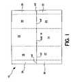
- FIG. 1is a plan view of a blank for forming an interior support structure for a convertible shipping and display container, according to a preferred embodiment of the invention.
- FIG. 2is a plan view of a blank for forming an exterior “Bliss”-style wrap for a convertible shipping and display container, according to a preferred embodiment of the invention.
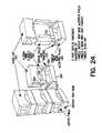
- FIG. 3 ais a perspective view of a container according to one embodiment of the invention, after discharge from the erecting machinery, and possibly prior to product loading (or possibly after), and prior to closure of the top.
- FIG. 3 bis a perspective view of the container of FIG. 3 a , prior to insertion of the internal support/divider.
- FIG. 3 cis a perspective view of a fully erected container according to the embodiment of FIGS. 3 a and 3 b.
- FIG. 3 dis a perspective view of a container according to FIGS. 3 a - 3 c being converted for 360° shopping.
- FIG. 3 eis a perspective view of a container according to FIGS. 3 a - 3 c being converted for stacked pallet or end-of-aisle merchandising.
- FIG. 4is a perspective view of an alternative embodiment of the invention, wherein the top portion of the wrap is provided with shortened top panels, to expose a portion of the top area of the container.
- FIG. 5is a perspective view of a further alternative embodiment of the invention, wherein the top portion of the wrap is provided with even more shortened top panels, to expose a portion of the top area of the container.
- FIG. 6is a perspective view of a further alternative embodiment of the invention, namely, a variation of the embodiment of FIGS. 1-3 e , having hand holes in the sidewalls of the bottom portion of the outer wrap.
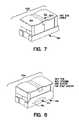
- FIG. 7is a perspective view of a further alternative embodiment of the invention, in which a tape seal is employed to enhance the closure of the top panel members of the outer wrap.
- FIG. 8is a perspective view of a variation of the alternative of the embodiment of FIG. 7 , including hand holes in the sidewalls of the bottom portion of the outer wrap.
- FIG. 9is a perspective view of a further alternative embodiment of the invention, wherein the outer wrap is provided with a side tear strip on one end of the container, and further including lines of weakness for enabling removal of one top panel and one upper end wall, only, leaving one top panel and one end wall in place.
- FIG. 10is a perspective view of the embodiment of FIG. 9 , wherein one tearstrip and one top panel and end wall combination have been removed.
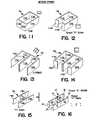
- FIG. 11is a perspective view of an alternative embodiment of the interior support structure for a convertible container according to the present invention, in the form of a simple tube, with a reduced scale top plan view adjacent thereto.
- FIG. 12is a perspective view of an alternative embodiment of the interior support structure for a convertible container according to the present invention, in the form of “C”-shape, with a reduced scale top plan view adjacent thereto.
- FIG. 13is a perspective view of an alternative embodiment of the interior support structure for a convertible container according to the present invention, in the form of an “E”-shape, with a reduced scale top plan view adjacent thereto.
- FIG. 14is a perspective view of an alternative embodiment of the interior support structure for a convertible container according to the present invention, in the form of a flanged “E”-shape, with a reduced scale top plan view adjacent thereto.
- FIG. 15is a perspective view of an alternative embodiment of the interior support structure for a convertible container according to the present invention, in the form of a simple “H”-shape, with a reduced scale top plan view adjacent thereto.
- FIG. 16is a further perspective view of an embodiment of the interior support structure for a convertible container according to the present invention, in the form of a flanged “H”-shape, as shown in the embodiment of FIGS. 1-3 , with a reduced scale top plan view adjacent thereto.
- FIG. 17is a perspective view of an alternative embodiment of the interior support structure for a convertible container according to the present invention, in the form of two spaced-apart “C”-shapes joined by a web, with a reduced scale top plan view adjacent thereto.
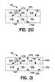
- FIG. 18is a plan view of a blank for forming the interior support structure shown in FIG. 11 .
- FIG. 19is a plan view of a blank for forming the interior support structure shown in FIG. 12 .
- FIG. 20is a plan view of a blank for forming the interior support structure shown in FIG. 13 .
- FIG. 21is a plan view of a blank for forming the interior support structure shown in FIG. 14 .
- FIG. 22is a plan view of a blank for forming the interior support structure shown in FIG. 15 .
- FIG. 23is a plan view of a blank for forming the interior support structure shown in FIG. 17 .
- FIG. 24is a perspective view of an alternative embodiment of the invention, incorporating a three-piece construction.
- FIG. 25is a plan view of a blank for a tray for use in the embodiment of FIG. 24 .
- FIG. 26is a plan view of a blank for a Bliss-style cap for use in the embodiment of FIG. 24 .
- FIG. 27is a plan view of a blank for an H-divider for use in the embodiment of FIG. 24 .
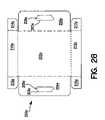
- FIG. 28is a plan view of a blank for an alternative tray construction, for use in the embodiment of FIG. 24 .
- FIG. 29is a plan view of a blank for an alternative tray construction, for use in the embodiment of FIG. 24 .
- FIG. 30is a plan view of a blank for an alternative Bliss-style cap for use in the embodiment of FIG. 24 .
- FIG. 31is a plan view of a blank for an alternative Bliss-style cap for use in the embodiment of FIG. 24 .
- FIG. 32is a plan view of a blank for an alternative H-divider for use in the embodiment of FIG. 24 .
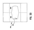
- FIG. 33is a plan view of a blank for an alternative H-divider for use in the embodiment of FIG. 24 .
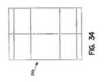
- FIG. 34is a plan view of a blank for an alternative H-divider for use in the embodiment of FIG. 24 .
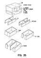
- FIG. 35is a further illustration of the three-piece Bliss-capped convertible shipping display system, with alternative divider/internal vertical support structure configurations.
- FIG. 36is a further illustration of the three-piece container system, showing how a container may be partially openable, through advantageous positioning of lines of weakness in the Bliss-style cap, as demonstrated in the two-piece embodiments.
- FIG. 37is a further illustration of alternative tray configurations for use in the three-piece embodiments of the present invention.
- the present inventionis directed to an improved “Bliss”-style shipping container, fabricated from paper, paperboard and/or corrugated paperboard, that is convertible to a display tray.
- the containergenerally, comprises a strong vertical structure (interior) providing general structural support, and an outer wrap, typically fabricated from a lighter weight paper, paperboard or corrugated paperboard material, providing containment and closure.
- the interior structureis advantageously connected (typically glued) strategically and minimally to the interior surfaces of the outer wrap and can be separated simply through hand articulation and the use of special design features such as perforated holes or tear strips.
- a particular distinguishing feature, among others, which is believed to enhance the performance of the containers of the present inventionrelates to the positioning and configuration of the minor flanges off of the horizontal base panel of the outer wrap.
- these minor flangesare positioned so that when such a container is formed, using known automatic forming equipment, known to those of ordinary skill in the art, the minor flanges fold up, wrap around, and are adhered to the outside surfaces of the vertical ends or sides of the package (depending upon the wrap direction). Erecting the flaps in this manner permits the horizontal base of the wrap to form the basis of a tray.
- Adhesiveis applied in a strategic manner, adhering only the upper portions of the interior to the upper wrap regions and by having the flanges extended off of the horizontal base area adhered to the outer ends or sides of the package.
- perforated design featuressuch as a tear strip and/or holes may be located.
- the designcan also be display converted to reveal only one side of the product. This option may be advantageously employed in a club store environment, for example, when the product is contemplated to be shopped directly out of the shipping container on the pallet, or off the shelf in a cooler.
- the merchandisermay either tear off the front and top of the upper portion of one side of the wrap for pallet or stacked merchandising, or the merchandiser can use the perforations/tear strip at the sides or ends to fully remove the interior for full tray display.
- One advantage of the present inventionis that the special features provide for containment and closure during distribution, but do not negatively affect the interior vertical support structure, which could compromise the stacking performance of the critical components of the container, and of the container itself.
- conversion to a display configurationis accomplished with relative ease and minimal effort.
- FIG. 1is a plan view of a blank for forming an interior support structure for a convertible shipping and display container, according to a preferred embodiment of the invention.
- Blank (interior support structure) 10includes center panels 12 , 14 , which are joined along fold line 16 , side panels 18 , 20 , 22 , 24 , and flanges 26 , 28 , 30 , 32 .
- the blankis formed from a suitably selected corrugated paperboard material, in which the corrugations run in a direction parallel to the short axis of blank 10 , i.e., perpendicular to fold line 16 .
- FIG. 2is a plan view of a blank for forming an exterior “Bliss”-style wrap for a convertible shipping and display container, according to a preferred embodiment of the invention.
- Blank (outer wrap) 40includes bottom panel 42 ; sidewalls 44 , 46 ; lower end panels 48 , 50 ; lower end flanges 52 , 54 , 56 and 58 ; tear strips 60 , 62 ; upper end panels 64 , 66 ; top panels 68 , 70 ; upper end flanges 72 , 74 , 76 and 78 ; and top flanges 80 , 82 , 84 and 86 .
- the blankis formed from a suitably selected corrugated paperboard material, in which the corrugations run in a direction parallel to the long axis of blank 40 .
- Blank (interior support structure) 10is erected in accordance with FIGS. 3 and 16 .
- Blank (outer wrap) 40is erected in accordance with FIG. 3 .
- FIG. 3is a development illustration showing how a container, formed from the components illustrated in FIGS. 1 and 2 , may be opened and broken down, to remove the upper portions of the outer wrap and the entirety of the interior support structure, to leave a display tray, for merchandising of the goods contained in the container.
- FIG. 3 cshows an erected, loaded and sealed container 100 ;
- FIG. 3 ashows the finished mechanically erected container ready for product loading through the top;
- FIG. 3 bshows the detailed erected form of the two package components as they related to one another within the erected, combined package;
- FIG. 3 dshows the package after it is converted for 360° display merchandising by removing the tear strips and drawing off the joined upper top and interior portions;
- FIG. 3 eshows the alternative method of converting the container for stacked pallet or end of aisle merchandising through the removal of a tear strip and a portion of the wrap.
- Flanges 80 , 82 , 84 and 86are firmly adhered to the outside surface panels 18 , 20 , 22 and 24 , and, in preferred embodiments of the invention, are not intended to be released during package articulation and conversion into a display configuration.
- flanges 72 , 74 , 76 and 78are firmly adhered to the inside vertical support structure 10 .
- adhesivemay be applied, e.g., to the inside surfaces of flanges 52 , 54 , 56 and 58 . Additional adhesive may be applied at various locations, as desired, by one of ordinary skill in the art, having the present disclosure before them, as required by the needs of any given application.
- internal flanges 26 , 28 , 30 and 32are preferably only spot adhered or not at all to side wall wrap sections 64 and 66 ( FIG. 3 d ). This gluing preferably should only take place on the internal support flanges 26 , 28 , 30 and 32 at a point above the tear strip 60 and 62 locations. It may be desired with some applications to have the flanges adhered at these locations, while other product applications may not require such a level of structural support.
- FIGS. 4-17illustrate alternative embodiments of either the interior vertical support structure and/or the outer wrap.
- those componentswhich are of particular interest, as having been modified from the basic embodiment of FIGS. 1 through 3 a - 3 e , are denoted by like reference numerals as the counterpart components of the basic embodiment, augmented by a letter.
- FIG. 4is a perspective view of an alternative embodiment of the invention, wherein the top portion of the wrap is provided with shortened top panels, to expose a portion of the top area of the container.
- top panels 68 a and 70 aare shortened, as are flanges 82 a and 86 a and the corresponding flanges (not shown, but present) on the rear side of assembly 100 a .
- the embodiment of FIG. 4may be provided with one or more punch-outs defined by perforations 47 a , in sidewall 46 a and its counterpart (not shown, but present) on the rear side of assembly 100 a . These punch-outs are adhesively affixed to adjoining surfaces of whatever internal support structure is used. To open the container, the punch-outs are pushed through (i.e., toward the tray interior), leaving a tray with newly formed hand holes. The punch-outs remain affixed to the support structure.
- FIG. 5is a perspective view of a further alternative embodiment of the invention, wherein the top portion of the wrap is provided with even more shortened top panels, to expose a portion of the top area of the container.
- top panels 68 b and 70 bare shortened, as are flanges 82 b and 86 b and the corresponding flanges (not shown, but present) on the rear side of assembly 100 b .
- the embodiment of FIG. 5may be provided with one or more punch-outs defined by perforations 47 b , in sidewall 46 b and its counterpart (not shown, but present) on the rear side of assembly 100 b . These punch-outs are adhesively affixed to adjoining surfaces of whatever internal support structure is used. To open the container, the punch-outs are pushed through (i.e., toward the tray interior), leaving a tray with newly formed hand holes. The punch-outs remain affixed to the support structure.
- FIG. 6is a perspective view of a further alternative embodiment of the invention, namely, a variation of the embodiment of FIGS. 1-3 e , having punch-outs defined by perforations 47 c in the sidewalls (e.g., sidewall 46 c ) of the bottom portion of the outer wrap 40 c .
- These punch-outsare adhesively affixed to adjoining surfaces of whatever internal support structure is used. To open the container, the punch-outs are pushed through (i.e., toward the tray interior), leaving a tray with newly formed hand holes. The punch-outs remain affixed to the support structure.
- FIG. 7is a perspective view of a further alternative embodiment 100 d of the invention, in which a tape seal 101 d is employed to provide the closure of the top panel members 68 d , 70 d of the outer wrap 40 d , inasmuch as no top flanges (such as flanges 82 , 84 , 86 and 88 of FIG. 2 ) are provided.
- a tape seal 101 dis employed to provide the closure of the top panel members 68 d , 70 d of the outer wrap 40 d , inasmuch as no top flanges (such as flanges 82 , 84 , 86 and 88 of FIG. 2 ) are provided.
- FIG. 8is a perspective view of a variation 100 e of the alternative of the embodiment of FIG. 7 , including punch-outs defined by perforations 47 e in the sidewalls of the bottom portion of the outer wrap 40 e .
- These punch-outsare adhesively affixed to adjoining surfaces of whatever internal support structure is used. To open the container, the punch-outs are pushed out; leaving a tray with newly formed hand holes. The punch-outs remain affixed to the support structure.
- FIG. 9is a perspective view of a further alternative embodiment 100 f of the invention, wherein the outer wrap 40 f is provided with a side tear strip 60 f on one end of the container, and further including lines of weakness 102 f , 104 f , 106 f , 108 f for enabling removal of one top panel 68 f and one upper end wall 64 f , only, leaving one top panel 70 f and one end wall (not shown but present) in place.
- FIG. 10is a perspective view of the embodiment of FIG. 9 , wherein one tearstrip and one top panel and end wall combination have been removed.
- FIG. 11is a perspective view of an alternative embodiment of the interior support structure 10 a for a convertible container according to the present invention, in the form of a simple tube.
- FIG. 18is a plan view of a blank, according to one embodiment of the invention, for forming the interior support structure shown in FIG. 11 .
- Blank 10 amay include back panel 110 a ; side panels 112 a , 114 a ; and front panels 116 a , 118 a .
- blank 10 amay be fabricated from any suitable paper, paperboard and/or corrugated paperboard material, of any suitable strength and thickness as desired.
- Blank 10 amay be double-ply.
- a double thicknessmay be obtained, by providing a double sized blank, that would comprise two blanks 10 a , as shown, arranged side-by-side, and connected along a fold line that would be placed where side edge 111 a is in FIG. 18 .
- FIG. 12is a perspective view of an alternative embodiment of the interior support structure for a convertible container according to the present invention, in the form of “C”-shape.
- FIG. 19is a plan view of a blank, according to one embodiment of the invention, for forming the interior support structure shown in FIG. 12 .
- Blank 10 bis substantially similar to the construction of blank 10 a , and may be similarly constituted and varied, except that front panels 116 a , 118 a of FIG. 11 have been shortened to provide flanges that give the erected interior vertical support structure a “C”-shape.
- FIG. 13is a perspective view of an alternative embodiment of the interior support structure for a convertible container according to the present invention, in the form of an “E”-shape.
- FIG. 20is a plan view of a blank, according to one embodiment of the invention, for forming the interior support structure shown in FIG. 13 .
- Blank 10 cmay be constructed from the same materials as described with respect to the embodiments of FIGS. 11 and 12 , and may be varied as to material, thickness and numbers of layers as may be desired.
- Blank 10 cis provided with center panels 110 c , 116 c , joined along fold line 111 c .
- Rear panels 112 c , 118 cemanate from center panels 110 c , 116 c , respectively, along fold lines 117 c , 119 c .
- Side panels 114 c , 120 cemanate from rear panels 112 c , 118 c , respectively, along fold lines 121 c , 123 c .
- panels 110 c , 116 care folded about line 111 c and preferably adhesively affixed to one another. Subsequent right angle folds around fold lines 117 c , 119 c , 121 c and 123 c , result in the configuration shown in FIG. 13 .
- FIG. 14is a perspective view of an alternative embodiment of the interior support structure for a convertible container according to the present invention, in the form of a flanged “E”-shape.
- FIG. 21is a plan view of a blank, according to one embodiment of the invention, for forming the interior support structure shown in FIG. 14 .
- Blank 10 dmay be constructed from the same materials as described with respect to the embodiments of FIG. 13 and may be varied as to material, thickness and numbers of layers as may be desired.
- Blank 10 dis provided with center panels 110 d , 116 d , joined along fold line 111 d .
- Rear panels 112 d , 118 demanate from center panels 110 d , 116 d , respectively, along fold lines 117 d , 119 d .
- Side panels 114 d , 120 demanate from rear panels 112 d , 118 d , respectively, along fold lines 121 d , 123 d .
- Flanges 122 d , 124 demanate from side panels 114 d , 120 d , respectively, along fold lines 125 d , 127 d , and are separated by cut 129 d .
- panels 110 d , 116 dare folded about line 111 d and preferably adhesively affixed to one another. Subsequent right-angle folds around fold lines 117 d , 119 d , 121 d , 123 d , 125 d and 127 d , result in the configuration shown in FIG. 14 .
- FIG. 15is a perspective view of an alternative embodiment of the interior support structure for a convertible container according to the present invention, in the form of a simple “H”-shape.
- FIG. 22is a plan view of a blank, according to one embodiment of the invention, for forming the interior support structure shown in FIG. 15 .
- Blank 10 ewhich may be constructed from the same variety and variation of materials, as described hereinabove comprises center panels 110 e , 112 e , joined by fold line 111 e .
- Leg panels 114 e , 118 eemanate from center panel 110 e , along fold lines 121 e , 123 e , respectively.
- Leg panelsare constructed from the same variety and variation of materials, as described hereinabove.
- panels 114 e and 116 eemanate from center panel 112 e , along fold lines 125 e , 127 e , respectively.
- Panels 114 e and 116 eare separated by cut 115 e
- panels 118 e and 120 eare separated by cut 119 e .
- To form the interior vertical support structurepanels 114 e and 116 e are folded about fold line 115 e , juxtaposed to one another and preferably adhesively affixed. Subsequent right angle folds about fold lines 121 e , 123 e , 125 e and 127 e , result in the configuration shown in FIG. 15 .
- FIG. 16is a further perspective view of an embodiment of the interior support structure for a convertible container according to the present invention, in the form of a flanged “H”-shape, as shown in the embodiment of FIGS. 1-3 e.
- FIG. 17is a perspective view of an alternative embodiment of the interior support structure for a convertible container according to the present invention, in the form of two spaced-apart “C”-shapes joined by a web.
- FIG. 23is a plan view of a blank, fabricated from the usual materials, as discussed herein elsewhere, for forming the interior support structure shown in FIG. 17 .
- Blank 10 fcomprises center panels 110 f and 112 f , joined along fold line 111 f .
- Panels 114 f , 116 femanate from center panel 110 f , along fold lines as indicated by the broken lines.
- Panels 118 f , 120 femanate from panels 114 f , 116 f , respectively.
- Flanges 122 f , 124 femanate from panels 118 f , 120 f , respectively.
- Panels 126 f , 128 femanate from center panel 112 f , along fold lines as indicated by the broken lines.
- Panels 130 f , 132 femanate from panels 126 f , 128 f , respectively.
- Flanges 134 f , 136 femanate from panels 130 f , 132 f , respectively.
- panels 110 f and 112 fare folded about fold line 111 f , juxtaposed to one another and preferably adhesively affixed. Subsequent right angle folds of the various panels, about the various fold lines (indicated by the broken lines), result in the configuration shown in FIG. 17 .
- FIG. 24is a perspective view of an alternative embodiment of the invention, incorporating a three-piece construction.
- a trayis formed, from a blank as shown in FIG. 25 .
- a divider for the productwhich also serves as the vertical support structure, is formed, from a blank as shown in FIG. 27 .
- a Bliss-style capis placed on top and adhesively affixed from the blank shown in FIG. 26 .
- tray 200is provided with zipper type tear strips 220 , and tabs 225 .
- the divider/vertical support structure 250is inserted and strategically adhered to the tray during mechanical erecting.
- Bliss-type cap 300is placed on top of support structure 250 , and adhesively affixed thereto. Opening of the container is accomplished by tearing the tear strips 220 (which are not adhesively affixed to the adjacent ends of the support structure 250 ), as shown in the left side of FIG. 24 .
- Tabs 225remain in place, and cap 300 and support structure 250 may be lifted together in their entirety, off of the remaining portions of tray 200 , leaving a 360-degree shoppable display tray.
- FIG. 25is a plan view of a blank for a tray 200 for use in the embodiment of FIG. 24 .
- blank 200includes bottom 202 ; sidewalls 204 , 206 ; end walls 210 , 212 ; and minor flaps 214 , 215 , 216 , 217 (to be adhesively affixed to the inside, or outside (a preferred embodiment) surfaces of sidewalls 204 , 206 ).
- the broken linesindicate the fold lines, and scalloped lines indicate perforations or other cuts for creating lines of weakness.
- the capmay be provided with perforations along the edges of the top panel, and across the top panel, to enable portions or the entirety of the top panel to be removed to enable access to the interior of the container.
- FIG. 26is a plan view of a blank for a Bliss-style cap for use in the embodiment of FIG. 24 .
- Blank 300includes top panel 302 ; top flanges 304 , 306 ; side panels 308 , 310 ; and side flanges 312 , 314 , 316 , 318 (which will be adhesively affixed to adjacent outside surfaces of support structure 250 , as shown in FIG. 24 ).
- FIG. 27is a plan view of a blank 250 for an H-divider for use in the embodiment of FIG. 24 .
- Broken linesindicate fold lines, while solid lines in the interior of the illustrated blank represent through cuts.
- Blank 250includes center panels 252 , 254 ; leg panels 256 , 258 , 260 , 262 ; and flanges 264 , 266 , 268 , 270 .
- Blank 250is folded in a manner similar to a similar support structure illustrated and described herein with respect to the two-piece embodiments.
- FIG. 28is a plan view of a blank for another alternative preferred embodiment of the tray construction, for use in the embodiment of FIG. 24 . Elements similar to those of blank 220 are given like reference numerals, with an “a” appended thereto.
- perforations 203 a , 207 ainstead of tear strips, in sidewalls 204 a and 206 a , are provided perforations 203 a , 207 a , defining punch-outs 205 a , 209 a .
- These punch-outsare adhesively affixed to adjoining surfaces of whatever internal support structure is used. To open the container, the punch-outs are pushed through (i.e., toward the tray interior), leaving a tray with newly formed hand holes.
- FIG. 28shows a preferred embodiment of the minor flaps for the base tray, as is also shown in FIG. 25 . That is, the minor flaps are disposed to the outside, so that firm gluing between the internal support component and the tray wall is possible. Having the minor flaps to the outside allows for flush contact making gluing easier to accomplish.
- FIG. 29is a plan view of a blank for an alternative tray construction 200 b , for use in the embodiment of FIG. 24 .
- Tray blank 200 bdiffers from the embodiment of FIG. 28 , in that instead of one punch-out per sidewall, there are three punch-outs in each sidewall.
- FIG. 30is a plan view of a blank for an alternative Bliss-style cap for use in the embodiment of FIG. 24 .
- Blank 300 aincludes top panel 302 a ; top flanges 304 a , 306 a ; side panels 308 a , 310 a ; and side flanges 312 a , 314 a , 316 a , 318 a (which will be adhesively affixed to adjacent outside surfaces of whatever support structure is used).
- the free edges of side panels 308 a , 310 aare straight.
- FIG. 31is a plan view of a blank for an alternative Bliss-style cap for use in the embodiment of FIG. 24 .
- Blank 300 bincludes top panel 302 b ; top flanges 304 b , 306 b ; side panels 308 b , 310 b ; and side flanges 312 b , 314 b , 316 b , 318 b (which will be adhesively affixed to adjacent outside surfaces of whatever support structure is used).
- a perforation 320 bdivides top panel 302 b , to permit partial opening of the container.
- FIG. 32is a plan view of a blank for an alternative H-divider for use in the embodiment of FIG. 24 .
- Blank 250 ais essentially functionally the same as blank 250 , except that an oblong hole 260 a is formed in the middle of center panels 252 a , 254 a , to define, when the panels are folded together, a “U” or “V” shaped opening or gap in the center of the support structure, which may facilitate access to goods in the interior of the container.
- FIG. 33is a plan view of a blank for an alternative H-divider for use in the embodiment of FIG. 24 .
- Blank 250 bis essentially the same as blank 250 a , except that no flanges are provided emanating from the leg panels.
- FIG. 34is a plan view of a blank 250 c for an alternative H-divider for use in the embodiment of FIG. 24 .
- FIG. 35is a further illustration of the three-piece Bliss-capped convertible shipping display system, with alternative divider/internal vertical support structure configurations. These alternative support structures may be fabricated from blanks, similar to those illustrated and described with respect to the two-piece convertible shipping container constructions described herein.
- FIG. 36is a further illustration of the three-piece container system, showing how a container may be partially openable, through advantageous positioning of lines of weakness in the Bliss-style cap, as demonstrated in the two-piece embodiments.
- FIG. 37is a further illustration of alternative tray configurations for use in the three-piece embodiments of the present invention.
Landscapes
- Engineering & Computer Science (AREA)
- Mechanical Engineering (AREA)
- Cartons (AREA)
Abstract
Description
Claims (6)
Priority Applications (1)
| Application Number | Priority Date | Filing Date | Title |
|---|---|---|---|
| US11/047,440US7455215B2 (en) | 2001-09-06 | 2005-01-31 | Shipping container convertible to a display container |
Applications Claiming Priority (3)
| Application Number | Priority Date | Filing Date | Title |
|---|---|---|---|
| US31761801P | 2001-09-06 | 2001-09-06 | |
| US10/236,618US7066379B2 (en) | 2001-09-06 | 2002-09-06 | Shipping container convertible to a display container |
| US11/047,440US7455215B2 (en) | 2001-09-06 | 2005-01-31 | Shipping container convertible to a display container |
Related Parent Applications (1)
| Application Number | Title | Priority Date | Filing Date |
|---|---|---|---|
| US10/236,618ContinuationUS7066379B2 (en) | 2001-09-06 | 2002-09-06 | Shipping container convertible to a display container |
Publications (2)
| Publication Number | Publication Date |
|---|---|
| US20050161496A1 US20050161496A1 (en) | 2005-07-28 |
| US7455215B2true US7455215B2 (en) | 2008-11-25 |
Family
ID=23234497
Family Applications (2)
| Application Number | Title | Priority Date | Filing Date |
|---|---|---|---|
| US10/236,618Expired - LifetimeUS7066379B2 (en) | 2001-09-06 | 2002-09-06 | Shipping container convertible to a display container |
| US11/047,440Expired - Fee RelatedUS7455215B2 (en) | 2001-09-06 | 2005-01-31 | Shipping container convertible to a display container |
Family Applications Before (1)
| Application Number | Title | Priority Date | Filing Date |
|---|---|---|---|
| US10/236,618Expired - LifetimeUS7066379B2 (en) | 2001-09-06 | 2002-09-06 | Shipping container convertible to a display container |
Country Status (4)
| Country | Link |
|---|---|
| US (2) | US7066379B2 (en) |
| CA (1) | CA2455838C (en) |
| MX (1) | MXPA04002015A (en) |
| WO (1) | WO2003022693A1 (en) |
Cited By (14)
| Publication number | Priority date | Publication date | Assignee | Title |
|---|---|---|---|---|
| US20110098167A1 (en)* | 2005-06-23 | 2011-04-28 | Otor, S.A. | Corrugated cardboard box with open-work flaps and assembly of blanks for obtaining same |
| US20110192809A1 (en)* | 2010-02-09 | 2011-08-11 | Eugenio Bueno Barrera | Structure for the placement, display and packing of merchandise |
| US8342335B2 (en) | 2009-04-30 | 2013-01-01 | Rock-Tenn Shared Services, Llc | Shelf-ready shipper display system |
| US8376141B2 (en) | 2009-04-30 | 2013-02-19 | Rock-Tenn Shared Services, Llc | Shelf-ready shipper display system |
| US20140263307A1 (en)* | 2013-03-15 | 2014-09-18 | Mars, Incorporated | Retail and recycle ready container |
| US20160332769A1 (en)* | 2015-05-11 | 2016-11-17 | Kellogg Company | Display-Ready Retail Case With Divide |
| US9919830B2 (en) | 2015-06-30 | 2018-03-20 | Westrock Shared Services, Llc | Container with a reinforcement structure and method of forming the same |
| US9938040B2 (en) | 2016-03-17 | 2018-04-10 | Westrock Shared Services, Llc | Blanks and methods for forming a shelf-ready display container |
| US9994356B2 (en) | 2016-03-16 | 2018-06-12 | Westrock Shared Services, Llc | Blanks and methods for forming a shelf-ready display container |
| US11270348B2 (en)* | 2017-05-19 | 2022-03-08 | Abl Ip Holding, Llc | Systems and methods for tracking products transported in shipping containers |
| US11507973B2 (en) | 2015-05-13 | 2022-11-22 | Abl Ip Holding, Llc | System and methods for determining location of pop displays with wireless beacons using mobile applications on mobile devices |
| USD980069S1 (en) | 2020-07-14 | 2023-03-07 | Ball Corporation | Metallic dispensing lid |
| US12168551B2 (en) | 2021-03-01 | 2024-12-17 | Ball Corporation | Metal container and end closure with seal |
| US12246909B1 (en) | 2023-02-07 | 2025-03-11 | Brunswick Corporation | Packaging box for outboard motor |
Families Citing this family (41)
| Publication number | Priority date | Publication date | Assignee | Title |
|---|---|---|---|---|
| DE20017940U1 (en) | 2000-10-19 | 2000-12-28 | MAP Medizintechnik für Arzt und Patient GmbH & Co KG, 82152 Planegg | Breathing mask for supplying a breathing gas to a mask user and a derivation device for deriving breathing gas |
| US7604114B2 (en)* | 2001-07-11 | 2009-10-20 | Delkor Systems, Inc. | Package assembly |
| DE10151984C5 (en) | 2001-10-22 | 2008-07-17 | Map Medizin-Technologie Gmbh | Application device for a breathing mask arrangement |
| US7320323B2 (en) | 2001-10-22 | 2008-01-22 | Map Medizin-Technologie Gmbh | Breathing mask device and application device and frontal support device thereof |
| ES2443417T3 (en) | 2002-09-06 | 2014-02-19 | Resmed Limited | Forehead pad for a respiratory mask |
| NZ608551A (en) | 2004-06-16 | 2014-10-31 | Resmed Ltd | Cushion for a respiratory mask assembly |
| CN101142128B (en) | 2005-03-14 | 2011-11-16 | 印刷包装国际公司 | Cartons with dispenser sections, blank and method for opening carton |
| US8459449B2 (en)* | 2005-06-01 | 2013-06-11 | International Paper Company | Easy-opening carton for shipping and storing cut paper |
| US8413801B2 (en)* | 2005-06-01 | 2013-04-09 | International Paper Company | Lidded container with a tear strip |
| CA2636959C (en)* | 2006-01-12 | 2010-10-19 | Graphic Packaging International, Inc. | Carton with dispenser |
| US9027826B2 (en)* | 2007-05-02 | 2015-05-12 | Watson Laboratories, Inc. | Frangible shipping carton and associated methods |
| US7819305B2 (en)* | 2008-05-15 | 2010-10-26 | York Container Company | Materials for and method for manufacturing packaging and resulting packaging |
| US8177117B2 (en)* | 2008-05-15 | 2012-05-15 | York Container Company | Materials for and method for manufacturing container with corner supports and resulting container |
| US8297490B2 (en)* | 2008-05-15 | 2012-10-30 | York Container Company | Materials for and method for manufacturing a container with corner supports and the resulting container |
| TWI340109B (en) | 2008-08-27 | 2011-04-11 | Pegatron Corp | Packing box structure |
| US7861916B2 (en)* | 2008-10-07 | 2011-01-04 | York Container Company | Materials for and method for manufacturing container with integrated divider and resulting container |
| ES1069694Y (en)* | 2009-01-30 | 2009-08-10 | Sanlucar Fruit S L | COMPARTMENTER FOR HORTOFRUTICOLAS AND SIMILAR PRODUCT BOXES |
| US7981017B2 (en)* | 2009-03-27 | 2011-07-19 | York Container Company | Materials for and method for manufacturing retail container and resulting retail container |
| US8292095B2 (en) | 2009-04-29 | 2012-10-23 | Rock-Tenn Shared Services, Llc | Expandable display system |
| US20110011922A1 (en)* | 2009-07-14 | 2011-01-20 | York Container Company | Materials for an method for manufacturing a divided container and resulting divided container |
| US20110030321A1 (en)* | 2009-08-05 | 2011-02-10 | Brand Kirsten L | Carton With Dispensing Feature |
| USD611270S1 (en) | 2009-09-30 | 2010-03-09 | S.C. Johnson & Son, Inc. | Display tray |
| US20110253777A1 (en)* | 2010-04-20 | 2011-10-20 | Georgia-Pacific Corrugated Llc. | Merchandizing carton |
| US8757563B2 (en)* | 2010-06-22 | 2014-06-24 | Pratt Industries, Inc. | Funnel and stand for bag |
| US8840072B2 (en) | 2010-06-22 | 2014-09-23 | Pratt Industries, Inc. | Bag stand |
| US8430297B2 (en) | 2010-10-07 | 2013-04-30 | The Dial Corporation | Shipping and display carton and blanks for producing same |
| US9359103B2 (en) | 2010-12-23 | 2016-06-07 | Green Bay Packaging, Inc. | Two-piece shipping container with frangible overlapping glued retainer areas |
| WO2012130528A1 (en)* | 2011-03-30 | 2012-10-04 | Unilever Plc | Tray and hood package |
| US9056715B2 (en) | 2011-07-18 | 2015-06-16 | Pratt Industries, Inc. | Bag stand |
| JP5783053B2 (en)* | 2012-01-11 | 2015-09-24 | 王子ホールディングス株式会社 | Cardboard box with divider |
| EP2969787A4 (en)* | 2013-03-14 | 2017-01-11 | Standard Knapp Inc. | Reclosable packing case and method of making same |
| US20140263591A1 (en) | 2013-03-14 | 2014-09-18 | Standard Knapp Inc. | Reclosable packing case and method of making same |
| CA2921808C (en) | 2013-08-23 | 2020-11-03 | Delkor Systems, Inc. | Convertible package assembly, blank and method therefor |
| US10046882B2 (en) | 2013-12-12 | 2018-08-14 | Malnove Incorporated | Reduced-width blank for forming a carton and sheet containing such blanks |
| US10543954B2 (en)* | 2016-03-24 | 2020-01-28 | Westrock Shared Services, Llc | Method and blanks for forming a shelf-ready display container |
| US9975662B1 (en)* | 2016-11-18 | 2018-05-22 | Julian Curtis Forman | Multi-chambered drink container |
| US11634277B2 (en) | 2019-09-06 | 2023-04-25 | Pratt Corrugated Holdings, Inc. | Lawn refuse bag insert |
| EP3825244A1 (en) | 2019-11-22 | 2021-05-26 | S.C. Johnson & Son, Inc. | Displayable shipping carton |
| USD929238S1 (en) | 2019-12-04 | 2021-08-31 | Pratt Corrugated Holdings, Inc. | Lawn refuse bag |
| USD935124S1 (en) | 2019-12-04 | 2021-11-02 | Pratt Corrugated Holdings, Inc. | Lawn refuse bag insert |
| US12330845B2 (en)* | 2022-12-07 | 2025-06-17 | Movie Mars, Inc. | Damage-resistant packaging box for shipping planar articles |
Citations (78)
| Publication number | Priority date | Publication date | Assignee | Title |
|---|---|---|---|---|
| US448813A (en) | 1891-03-24 | Collapsible paper box | ||
| US1262992A (en) | 1917-05-08 | 1918-04-16 | Constantine Stephano | Receptacle. |
| US1430149A (en) | 1920-11-15 | 1922-09-26 | Herbert R Bliss | Shipping case |
| US1794821A (en) | 1929-09-04 | 1931-03-03 | Oliver B Andrews | Compound box |
| US2012942A (en) | 1934-12-29 | 1935-09-03 | E N Rowell Co Inc | Container |
| US2193925A (en) | 1938-03-24 | 1940-03-19 | Joseph G Huye | Box |
| US2581105A (en) | 1948-05-25 | 1952-01-01 | Container Corp | Textile container with slotted corners |
| US2671597A (en) | 1949-06-22 | 1954-03-09 | Container Corp | Shipping container |
| US2671600A (en) | 1949-10-25 | 1954-03-09 | Container Corp | Shipping container |
| US2766923A (en) | 1953-10-19 | 1956-10-16 | Container Corp | Container with reinforced closure |
| US2822970A (en) | 1955-08-24 | 1958-02-11 | Shoup Owens Inc | Container |
| US2904239A (en) | 1953-03-30 | 1959-09-15 | Isaac L Wilcox | Collapsible rectangular container |
| US2920757A (en) | 1958-01-30 | 1960-01-12 | Owens Illinois Glass Co | Carton construction |
| US2925210A (en) | 1956-10-08 | 1960-02-16 | Crown Zellerbach Corp | Heavy-duty container for bulk material |
| US2989226A (en) | 1957-06-04 | 1961-06-20 | Henry D Swartz | Collapsible containers |
| US3167179A (en) | 1960-09-29 | 1965-01-26 | Schenley Ind Inc | Merchandising and shipping device |
| US3260440A (en) | 1964-03-09 | 1966-07-12 | Hoerner Boxes Inc | One piece cell former |
| US3348667A (en) | 1966-02-23 | 1967-10-24 | Clorox Co | Combination shipping and display container |
| US3365110A (en)* | 1965-12-09 | 1968-01-23 | Procter & Gamble | Package divider |
| US3425544A (en) | 1965-10-14 | 1969-02-04 | Reynolds Metals Co | Package construction |
| US3428234A (en) | 1967-01-19 | 1969-02-18 | Weyerhaeuser Co | Reinforced telescopic container |
| US3433401A (en) | 1967-06-19 | 1969-03-18 | Owens Illinois Inc | Bulk carrier |
| USRE26557E (en) | 1968-03-26 | 1969-03-25 | Houstoncontainer | |
| US3650459A (en) | 1969-12-11 | 1972-03-21 | Mead Corp | Pallet type shipping container |
| US3653495A (en) | 1970-09-25 | 1972-04-04 | Lone Star Container Corp | Shipping and display container |
| US3810573A (en) | 1972-03-23 | 1974-05-14 | L Russell | Two piece storage and shipping carton |
| US3850363A (en) | 1973-07-16 | 1974-11-26 | L Jacobs | Carton |
| US3899123A (en) | 1972-10-13 | 1975-08-12 | Crown Zellerbach Corp | Collapsible bliss-type container |
| US3921893A (en) | 1974-06-24 | 1975-11-25 | Owens Illinois Inc | Container |
| US3985286A (en) | 1976-04-01 | 1976-10-12 | Continental Can Company, Inc. | Six-cell box divider |
| US4030600A (en) | 1975-06-26 | 1977-06-21 | Connelly Containers, Inc. | Collapsible bulk shipping container |
| US4184625A (en) | 1978-12-28 | 1980-01-22 | Crown Zellerbach Corporation | Container for fresh products such as asparagus |
| US4191288A (en) | 1976-08-11 | 1980-03-04 | Packaging Corporation Of America | Shipper display unit |
| US4282999A (en) | 1978-05-30 | 1981-08-11 | Moen Lenard E | H-divider containers |
| US4328924A (en) | 1981-01-12 | 1982-05-11 | The Mead Corporation | Article container |
| US4427108A (en) | 1982-02-24 | 1984-01-24 | General Foods Limited | Stackable display unit |
| US4512511A (en) | 1982-03-20 | 1985-04-23 | Somerville Belkin Industries Limited | Divided display container |
| US4519538A (en) | 1983-08-12 | 1985-05-28 | Namio Omichi | Packing and displaying carton, and blank plate therefor |
| US4635795A (en) | 1984-10-12 | 1987-01-13 | The Procter & Gamble Company | Easy-openable see-through container |
| US4697699A (en) | 1985-11-06 | 1987-10-06 | Tootsie Roll Industries, Inc. | Shipping container |
| US4705162A (en) | 1986-11-13 | 1987-11-10 | Kupersmit Julius B | Multiple display carton shipping package |
| US4779737A (en) | 1986-02-10 | 1988-10-25 | Lion Corporation | Divisible package box |
| US4784271A (en) | 1987-11-20 | 1988-11-15 | The Procter & Gamble Company | Tear strip openable shipping/display container with butt joint |
| US4793494A (en) | 1987-06-08 | 1988-12-27 | Baxter Travenol Laboratories, Inc. | Break-apart container |
| US4848651A (en) | 1988-08-10 | 1989-07-18 | Hartness International, Inc. | Carton for shipping or displaying of articles |
| US4871067A (en) | 1986-10-30 | 1989-10-03 | In-Pak S.P.A. | Perfected case for packaging products of different kinds in cases |
| GB2221670A (en) | 1988-08-10 | 1990-02-14 | St Regis Packaging Ltd | Cartons having tear strips for opening |
| US4974773A (en) | 1986-10-14 | 1990-12-04 | Alexander Packaging Equipment Pty. Ltd. | Carton and blank therefor |
| US5105950A (en) | 1990-09-17 | 1992-04-21 | Moore Business Forms, Inc. | Zip off lid for two piece crushable carton |
| US5143278A (en) | 1991-05-02 | 1992-09-01 | Packaging Systems, Inc. | Reinforced bulk material box |
| US5293991A (en) | 1990-04-03 | 1994-03-15 | Kraft General Foods R&D, Inc. | Combined shipping and presentation package |
| US5419485A (en) | 1994-06-03 | 1995-05-30 | Packaging Systems, Inc. | End opening reinforced bulk material box |
| US5443205A (en) | 1994-03-24 | 1995-08-22 | Kellogg Company | Shipping/display container |
| US5464149A (en) | 1993-12-29 | 1995-11-07 | Lever Brothers Company | H-partition and display case |
| US5505369A (en) | 1994-03-15 | 1996-04-09 | Kellogg Company | Knocked-down flat preform for a shipping and display container |
| US5507430A (en) | 1994-10-26 | 1996-04-16 | Stone Container Corporation | Shipping container apparatus convertible for use as a display apparatus for goods |
| US5520325A (en) | 1995-01-06 | 1996-05-28 | International Paper Company | Channel H divider pack |
| US5555982A (en) | 1994-12-29 | 1996-09-17 | Stone Container Corporation | Convertible shipping container-display apparatus |
| US5657872A (en) | 1995-02-06 | 1997-08-19 | The Procter & Gamble Company | Shipping/display container |
| GB2313828A (en) | 1996-06-03 | 1997-12-10 | Smith David S Packaging | Carton and blank therefor with tear strips |
| US5758818A (en) | 1997-03-28 | 1998-06-02 | Mott's Inc. | Dividable multi-compartment container |
| US5853120A (en) | 1996-07-31 | 1998-12-29 | Stone Container Corporation | Tray apparatus with reinforced corner structure |
| US5950915A (en) | 1997-10-14 | 1999-09-14 | Moen; Lenard E. | High strength stackable container |
| US5950911A (en) | 1997-06-19 | 1999-09-14 | Union Camp Corporation | Device for holding a plurality of containers |
| US5967406A (en) | 1998-06-09 | 1999-10-19 | Georgia Pacific Corporation | Container convertible between shipping and shipping/display modes |
| US6168027B1 (en) | 1998-10-19 | 2001-01-02 | Fort James Corporation | Shipping/display box having tear-out segments |
| US6311891B1 (en) | 2000-03-02 | 2001-11-06 | Weyerhaeuser Company | Bliss container with E divider |
| US6352199B1 (en) | 2000-05-01 | 2002-03-05 | Weyerhauser Company | Three-piece corrugated paperboard container |
| US6499655B1 (en) | 2000-03-11 | 2002-12-31 | Lenard E. Moen | Compartmented container |
| US6508395B2 (en) | 2001-03-12 | 2003-01-21 | Stone Container Corporation | Stackable shipping container |
| US20030159964A1 (en) | 2002-02-25 | 2003-08-28 | Mcleod Michael B. | Case ready stackable tray designs |
| US20030234284A1 (en) | 2002-06-24 | 2003-12-25 | Chiera Karen M. | Carton with reducibility feature |
| US6719191B1 (en) | 2002-08-22 | 2004-04-13 | Longview Fibre Co | Stackable bliss-type container |
| US20040084515A1 (en) | 2002-11-01 | 2004-05-06 | Oscar Rochefort | Quadcorner tray wrapper designs |
| US20040214705A1 (en) | 2003-04-24 | 2004-10-28 | Gardner Jeffrey M. | Method of forming shipping containers |
| US20040222127A1 (en) | 2003-05-05 | 2004-11-11 | Mcleod Michael B. | Wraparound-style shipping containers convertible to dispensing or display containers |
| US20050000853A1 (en) | 2001-08-02 | 2005-01-06 | Oscar Rochefort | Shipping container convertible to dispensing or all around display container |
| US6935504B2 (en) | 2002-10-18 | 2005-08-30 | Smurfit-Stone Container Enterprises, Inc. | Passive interlock structure |
Family Cites Families (1)
| Publication number | Priority date | Publication date | Assignee | Title |
|---|---|---|---|---|
| US5556982A (en)* | 1985-01-14 | 1996-09-17 | Neorx Corporation | Metal radionuclide labeled proteins for diagnosis and therapy |
- 2002
- 2002-09-06CACA002455838Apatent/CA2455838C/ennot_activeExpired - Fee Related
- 2002-09-06MXMXPA04002015Apatent/MXPA04002015A/enactiveIP Right Grant
- 2002-09-06USUS10/236,618patent/US7066379B2/ennot_activeExpired - Lifetime
- 2002-09-06WOPCT/US2002/028276patent/WO2003022693A1/ennot_activeApplication Discontinuation
- 2005
- 2005-01-31USUS11/047,440patent/US7455215B2/ennot_activeExpired - Fee Related
Patent Citations (80)
| Publication number | Priority date | Publication date | Assignee | Title |
|---|---|---|---|---|
| US448813A (en) | 1891-03-24 | Collapsible paper box | ||
| US1262992A (en) | 1917-05-08 | 1918-04-16 | Constantine Stephano | Receptacle. |
| US1430149A (en) | 1920-11-15 | 1922-09-26 | Herbert R Bliss | Shipping case |
| US1794821A (en) | 1929-09-04 | 1931-03-03 | Oliver B Andrews | Compound box |
| US2012942A (en) | 1934-12-29 | 1935-09-03 | E N Rowell Co Inc | Container |
| US2193925A (en) | 1938-03-24 | 1940-03-19 | Joseph G Huye | Box |
| US2581105A (en) | 1948-05-25 | 1952-01-01 | Container Corp | Textile container with slotted corners |
| US2671597A (en) | 1949-06-22 | 1954-03-09 | Container Corp | Shipping container |
| US2671600A (en) | 1949-10-25 | 1954-03-09 | Container Corp | Shipping container |
| US2904239A (en) | 1953-03-30 | 1959-09-15 | Isaac L Wilcox | Collapsible rectangular container |
| US2766923A (en) | 1953-10-19 | 1956-10-16 | Container Corp | Container with reinforced closure |
| US2822970A (en) | 1955-08-24 | 1958-02-11 | Shoup Owens Inc | Container |
| US2925210A (en) | 1956-10-08 | 1960-02-16 | Crown Zellerbach Corp | Heavy-duty container for bulk material |
| US2989226A (en) | 1957-06-04 | 1961-06-20 | Henry D Swartz | Collapsible containers |
| US2920757A (en) | 1958-01-30 | 1960-01-12 | Owens Illinois Glass Co | Carton construction |
| US3167179A (en) | 1960-09-29 | 1965-01-26 | Schenley Ind Inc | Merchandising and shipping device |
| US3260440A (en) | 1964-03-09 | 1966-07-12 | Hoerner Boxes Inc | One piece cell former |
| US3425544A (en) | 1965-10-14 | 1969-02-04 | Reynolds Metals Co | Package construction |
| US3365110A (en)* | 1965-12-09 | 1968-01-23 | Procter & Gamble | Package divider |
| US3348667A (en) | 1966-02-23 | 1967-10-24 | Clorox Co | Combination shipping and display container |
| US3428234A (en) | 1967-01-19 | 1969-02-18 | Weyerhaeuser Co | Reinforced telescopic container |
| US3433401A (en) | 1967-06-19 | 1969-03-18 | Owens Illinois Inc | Bulk carrier |
| USRE26557E (en) | 1968-03-26 | 1969-03-25 | Houstoncontainer | |
| US3650459A (en) | 1969-12-11 | 1972-03-21 | Mead Corp | Pallet type shipping container |
| US3653495A (en) | 1970-09-25 | 1972-04-04 | Lone Star Container Corp | Shipping and display container |
| US3810573A (en) | 1972-03-23 | 1974-05-14 | L Russell | Two piece storage and shipping carton |
| US3899123A (en) | 1972-10-13 | 1975-08-12 | Crown Zellerbach Corp | Collapsible bliss-type container |
| US3850363A (en) | 1973-07-16 | 1974-11-26 | L Jacobs | Carton |
| US3921893A (en) | 1974-06-24 | 1975-11-25 | Owens Illinois Inc | Container |
| US4030600A (en) | 1975-06-26 | 1977-06-21 | Connelly Containers, Inc. | Collapsible bulk shipping container |
| US3985286A (en) | 1976-04-01 | 1976-10-12 | Continental Can Company, Inc. | Six-cell box divider |
| US4191288A (en) | 1976-08-11 | 1980-03-04 | Packaging Corporation Of America | Shipper display unit |
| US4282999A (en) | 1978-05-30 | 1981-08-11 | Moen Lenard E | H-divider containers |
| US4184625A (en) | 1978-12-28 | 1980-01-22 | Crown Zellerbach Corporation | Container for fresh products such as asparagus |
| US4328924A (en) | 1981-01-12 | 1982-05-11 | The Mead Corporation | Article container |
| US4427108A (en) | 1982-02-24 | 1984-01-24 | General Foods Limited | Stackable display unit |
| US4512511A (en) | 1982-03-20 | 1985-04-23 | Somerville Belkin Industries Limited | Divided display container |
| US4519538A (en) | 1983-08-12 | 1985-05-28 | Namio Omichi | Packing and displaying carton, and blank plate therefor |
| US4635795A (en) | 1984-10-12 | 1987-01-13 | The Procter & Gamble Company | Easy-openable see-through container |
| US4697699A (en) | 1985-11-06 | 1987-10-06 | Tootsie Roll Industries, Inc. | Shipping container |
| US4779737A (en) | 1986-02-10 | 1988-10-25 | Lion Corporation | Divisible package box |
| US4974773A (en) | 1986-10-14 | 1990-12-04 | Alexander Packaging Equipment Pty. Ltd. | Carton and blank therefor |
| US4871067A (en) | 1986-10-30 | 1989-10-03 | In-Pak S.P.A. | Perfected case for packaging products of different kinds in cases |
| US4705162A (en) | 1986-11-13 | 1987-11-10 | Kupersmit Julius B | Multiple display carton shipping package |
| US4793494A (en) | 1987-06-08 | 1988-12-27 | Baxter Travenol Laboratories, Inc. | Break-apart container |
| US4784271A (en) | 1987-11-20 | 1988-11-15 | The Procter & Gamble Company | Tear strip openable shipping/display container with butt joint |
| US4848651A (en) | 1988-08-10 | 1989-07-18 | Hartness International, Inc. | Carton for shipping or displaying of articles |
| GB2221670A (en) | 1988-08-10 | 1990-02-14 | St Regis Packaging Ltd | Cartons having tear strips for opening |
| US5293991A (en) | 1990-04-03 | 1994-03-15 | Kraft General Foods R&D, Inc. | Combined shipping and presentation package |
| US5105950A (en) | 1990-09-17 | 1992-04-21 | Moore Business Forms, Inc. | Zip off lid for two piece crushable carton |
| US5143278A (en) | 1991-05-02 | 1992-09-01 | Packaging Systems, Inc. | Reinforced bulk material box |
| US5464149A (en) | 1993-12-29 | 1995-11-07 | Lever Brothers Company | H-partition and display case |
| US5505369A (en) | 1994-03-15 | 1996-04-09 | Kellogg Company | Knocked-down flat preform for a shipping and display container |
| US5443205A (en) | 1994-03-24 | 1995-08-22 | Kellogg Company | Shipping/display container |
| US5419485A (en) | 1994-06-03 | 1995-05-30 | Packaging Systems, Inc. | End opening reinforced bulk material box |
| US5507430A (en) | 1994-10-26 | 1996-04-16 | Stone Container Corporation | Shipping container apparatus convertible for use as a display apparatus for goods |
| US5555982A (en) | 1994-12-29 | 1996-09-17 | Stone Container Corporation | Convertible shipping container-display apparatus |
| US5520325A (en) | 1995-01-06 | 1996-05-28 | International Paper Company | Channel H divider pack |
| US5657872A (en) | 1995-02-06 | 1997-08-19 | The Procter & Gamble Company | Shipping/display container |
| GB2313828A (en) | 1996-06-03 | 1997-12-10 | Smith David S Packaging | Carton and blank therefor with tear strips |
| US5853120A (en) | 1996-07-31 | 1998-12-29 | Stone Container Corporation | Tray apparatus with reinforced corner structure |
| US5979746A (en) | 1996-07-31 | 1999-11-09 | Stone Container Corporation | Tray apparatus with reinforced corner structure |
| US5758818A (en) | 1997-03-28 | 1998-06-02 | Mott's Inc. | Dividable multi-compartment container |
| US5950911A (en) | 1997-06-19 | 1999-09-14 | Union Camp Corporation | Device for holding a plurality of containers |
| US5950915A (en) | 1997-10-14 | 1999-09-14 | Moen; Lenard E. | High strength stackable container |
| US5967406A (en) | 1998-06-09 | 1999-10-19 | Georgia Pacific Corporation | Container convertible between shipping and shipping/display modes |
| US6168027B1 (en) | 1998-10-19 | 2001-01-02 | Fort James Corporation | Shipping/display box having tear-out segments |
| US6311891B1 (en) | 2000-03-02 | 2001-11-06 | Weyerhaeuser Company | Bliss container with E divider |
| US6520898B1 (en) | 2000-03-11 | 2003-02-18 | Lenard E. Moen | Process of making a compartmented container |
| US6499655B1 (en) | 2000-03-11 | 2002-12-31 | Lenard E. Moen | Compartmented container |
| US6352199B1 (en) | 2000-05-01 | 2002-03-05 | Weyerhauser Company | Three-piece corrugated paperboard container |
| US6508395B2 (en) | 2001-03-12 | 2003-01-21 | Stone Container Corporation | Stackable shipping container |
| US20050000853A1 (en) | 2001-08-02 | 2005-01-06 | Oscar Rochefort | Shipping container convertible to dispensing or all around display container |
| US20030159964A1 (en) | 2002-02-25 | 2003-08-28 | Mcleod Michael B. | Case ready stackable tray designs |
| US20030234284A1 (en) | 2002-06-24 | 2003-12-25 | Chiera Karen M. | Carton with reducibility feature |
| US6719191B1 (en) | 2002-08-22 | 2004-04-13 | Longview Fibre Co | Stackable bliss-type container |
| US6935504B2 (en) | 2002-10-18 | 2005-08-30 | Smurfit-Stone Container Enterprises, Inc. | Passive interlock structure |
| US20040084515A1 (en) | 2002-11-01 | 2004-05-06 | Oscar Rochefort | Quadcorner tray wrapper designs |
| US20040214705A1 (en) | 2003-04-24 | 2004-10-28 | Gardner Jeffrey M. | Method of forming shipping containers |
| US20040222127A1 (en) | 2003-05-05 | 2004-11-11 | Mcleod Michael B. | Wraparound-style shipping containers convertible to dispensing or display containers |
Cited By (22)
| Publication number | Priority date | Publication date | Assignee | Title |
|---|---|---|---|---|
| US20110098167A1 (en)* | 2005-06-23 | 2011-04-28 | Otor, S.A. | Corrugated cardboard box with open-work flaps and assembly of blanks for obtaining same |
| US9180996B2 (en) | 2005-06-23 | 2015-11-10 | Otor, S.A. | Corrugated cardboard box with open-work flaps and set of blanks for obtaining same |
| US9187204B2 (en)* | 2005-06-23 | 2015-11-17 | Otor, S.A. | Corrugated cardboard box with open-work flaps and set of blanks for obtaining same |
| US10273043B2 (en) | 2009-04-30 | 2019-04-30 | Westrock Shared Services, Llc | Shelf-ready shipper display system |
| US8342335B2 (en) | 2009-04-30 | 2013-01-01 | Rock-Tenn Shared Services, Llc | Shelf-ready shipper display system |
| US8376141B2 (en) | 2009-04-30 | 2013-02-19 | Rock-Tenn Shared Services, Llc | Shelf-ready shipper display system |
| US8789703B2 (en) | 2009-04-30 | 2014-07-29 | Rock-Tenn Shared Services, Llc | Shelf-ready shipper display system |
| US11794948B2 (en) | 2009-04-30 | 2023-10-24 | Westrock Shared Services, Llc | Shelf-ready shipper display system |
| US9382041B2 (en) | 2009-04-30 | 2016-07-05 | Westrock Shared Services, Llc | Shelf-ready shipper display system |
| US20110192809A1 (en)* | 2010-02-09 | 2011-08-11 | Eugenio Bueno Barrera | Structure for the placement, display and packing of merchandise |
| US20140263307A1 (en)* | 2013-03-15 | 2014-09-18 | Mars, Incorporated | Retail and recycle ready container |
| US9193521B2 (en)* | 2013-03-15 | 2015-11-24 | Mars, Incorporated | Retail and recycle ready container |
| US9776760B2 (en)* | 2015-05-11 | 2017-10-03 | Kellogg Company | Display-ready retail case with divide |
| US20160332769A1 (en)* | 2015-05-11 | 2016-11-17 | Kellogg Company | Display-Ready Retail Case With Divide |
| US11507973B2 (en) | 2015-05-13 | 2022-11-22 | Abl Ip Holding, Llc | System and methods for determining location of pop displays with wireless beacons using mobile applications on mobile devices |
| US9919830B2 (en) | 2015-06-30 | 2018-03-20 | Westrock Shared Services, Llc | Container with a reinforcement structure and method of forming the same |
| US9994356B2 (en) | 2016-03-16 | 2018-06-12 | Westrock Shared Services, Llc | Blanks and methods for forming a shelf-ready display container |
| US9938040B2 (en) | 2016-03-17 | 2018-04-10 | Westrock Shared Services, Llc | Blanks and methods for forming a shelf-ready display container |
| US11270348B2 (en)* | 2017-05-19 | 2022-03-08 | Abl Ip Holding, Llc | Systems and methods for tracking products transported in shipping containers |
| USD980069S1 (en) | 2020-07-14 | 2023-03-07 | Ball Corporation | Metallic dispensing lid |
| US12168551B2 (en) | 2021-03-01 | 2024-12-17 | Ball Corporation | Metal container and end closure with seal |
| US12246909B1 (en) | 2023-02-07 | 2025-03-11 | Brunswick Corporation | Packaging box for outboard motor |
Also Published As
| Publication number | Publication date |
|---|---|
| WO2003022693A1 (en) | 2003-03-20 |
| CA2455838A1 (en) | 2003-03-20 |
| MXPA04002015A (en) | 2004-06-07 |
| US7066379B2 (en) | 2006-06-27 |
| CA2455838C (en) | 2007-06-19 |
| US20030116613A1 (en) | 2003-06-26 |
| US20050161496A1 (en) | 2005-07-28 |
Similar Documents
| Publication | Publication Date | Title |
|---|---|---|
| US7455215B2 (en) | Shipping container convertible to a display container | |
| US5957294A (en) | Display container having reinforcing insert | |
| US6974033B2 (en) | Wraparound-style shipping containers convertible to dispensing or display containers | |
| US7451878B2 (en) | Shipping container convertible to dispensing or all around display container | |
| US6189780B1 (en) | Display container having integral reinforcement | |
| US6948617B2 (en) | Stackable container with support flanges | |
| US5413276A (en) | Plural-component one-piece shipping and retail display carton | |
| US6129211A (en) | Rectangular shipping box and display container | |
| US5950914A (en) | Shipping and display container | |
| US5588585A (en) | Automatic set-up carton with corner posts | |
| US9221576B2 (en) | Display ready container assembly | |
| KR950005283Y1 (en) | Separable display carton | |
| US20020074388A1 (en) | Container having improved stacking strength | |
| US20010001447A1 (en) | Fold-in-half shipping/display box | |
| US9114904B2 (en) | Stackable display container with box portion and reinforcing layer | |
| EP3184459A1 (en) | Shipping container convertible into a display configuration | |
| US20030146126A1 (en) | Stackable container having support flanges | |
| US6669081B2 (en) | Shipping and display case | |
| US20060038000A1 (en) | Stacking display containers | |
| WO1998003404A1 (en) | Carton with support liner | |
| IES20000799A2 (en) | Stackable carton with reinforced corners | |
| AU2020256374A1 (en) | Shipping and display container and blank for forming same | |
| AU2021221593A1 (en) | Shipping and display container and blank for forming same | |
| GB2274451A (en) | Lid for tray for packs of foodstuff | |
| IE970528A1 (en) | A carton |
Legal Events
| Date | Code | Title | Description |
|---|---|---|---|
| AS | Assignment | Owner name:STONE CONTAINER CORPORATION, ILLINOIS Free format text:ASSIGNMENT OF ASSIGNORS INTEREST;ASSIGNORS:MCLEOD, MICHAEL B.;ROCHEFORT, OSCAR;REEL/FRAME:016238/0268 Effective date:20021111 | |
| AS | Assignment | Owner name:SMURFIT-STONE CONTAINER ENTERPRISES, INC., ILLINOI Free format text:MERGER;ASSIGNOR:STONE CONTAINER CORPORATION;REEL/FRAME:016417/0791 Effective date:20041101 | |
| STCF | Information on status: patent grant | Free format text:PATENTED CASE | |
| AS | Assignment | Owner name:JPMORGAN CHASE BANK, N.A., AS ADMINISTRATIVE AGENT Free format text:SECURITY AGREEMENT;ASSIGNOR:SMURFIT-STONE CONTAINER CORPORATION (F/K/A SMURFIT STONE CONTAINER ENTERPRISES, INC.);REEL/FRAME:024640/0501 Effective date:20100630 | |
| AS | Assignment | Owner name:DEUTSCHE BANK AG NEW YORK BRANCH, AS SECURITY AGEN Free format text:SECURITY AGREEMENT;ASSIGNOR:SMURFIT-STONE CONTAINER CORPORATION (FORMERLY KNOWN AS SMURFIT-STONE CONTAINER ENTERPRISES, INC.);REEL/FRAME:024662/0368 Effective date:20100630 | |
| AS | Assignment | Owner name:SMURFIT STONE CONTAINER CORPORATION, GEORGIA Free format text:RELEASE BY SECURED PARTY;ASSIGNOR:JPMORGAN CHASE BANK, N.A., AS ADMINISTRATIVE AGENT;REEL/FRAME:026415/0130 Effective date:20110527 Owner name:SMURFIT STONE CONTAINER CORPORATION, GEORGIA Free format text:RELEASE BY SECURED PARTY;ASSIGNOR:DEUTSCHE BANK AG NEW YORK BRANCH, AS SECURITY AGENT;REEL/FRAME:026414/0273 Effective date:20110527 | |
| FPAY | Fee payment | Year of fee payment:4 | |
| SULP | Surcharge for late payment | ||
| AS | Assignment | Owner name:SMURFIT-STONE CONTAINER CORPORATION, ILLINOIS Free format text:MERGER;ASSIGNOR:SMURFIT-STONE CONTAINER ENTERPRISES, INC;REEL/FRAME:031074/0590 Effective date:20100708 | |
| AS | Assignment | Owner name:ROCKTENN CP, LLC, GEORGIA Free format text:MERGER;ASSIGNOR:SMURFIT-STONE CONTAINER CORPORATION;REEL/FRAME:031122/0131 Effective date:20110527 | |
| AS | Assignment | Owner name:ROCK-TENN SHARED SERVICES, LLC, GEORGIA Free format text:ASSIGNMENT OF ASSIGNORS INTEREST;ASSIGNOR:ROCKTENN CP, LLC;REEL/FRAME:031247/0991 Effective date:20130920 | |
| AS | Assignment | Owner name:WESTROCK SHARED SERVICES, LLC, GEORGIA Free format text:CHANGE OF NAME;ASSIGNOR:ROCK-TENN SHARED SERVICES, LLC;REEL/FRAME:037057/0404 Effective date:20150901 | |
| FPAY | Fee payment | Year of fee payment:8 | |
| FEPP | Fee payment procedure | Free format text:MAINTENANCE FEE REMINDER MAILED (ORIGINAL EVENT CODE: REM.); ENTITY STATUS OF PATENT OWNER: LARGE ENTITY | |
| LAPS | Lapse for failure to pay maintenance fees | Free format text:PATENT EXPIRED FOR FAILURE TO PAY MAINTENANCE FEES (ORIGINAL EVENT CODE: EXP.); ENTITY STATUS OF PATENT OWNER: LARGE ENTITY | |
| STCH | Information on status: patent discontinuation | Free format text:PATENT EXPIRED DUE TO NONPAYMENT OF MAINTENANCE FEES UNDER 37 CFR 1.362 | |
| FP | Lapsed due to failure to pay maintenance fee | Effective date:20201125 |