US7454494B1 - Apparatus and method for actively analyzing a data packet delivery path - Google Patents
Apparatus and method for actively analyzing a data packet delivery pathDownload PDFInfo
- Publication number
- US7454494B1 US7454494B1US10/337,653US33765303AUS7454494B1US 7454494 B1US7454494 B1US 7454494B1US 33765303 AUS33765303 AUS 33765303AUS 7454494 B1US7454494 B1US 7454494B1
- Authority
- US
- United States
- Prior art keywords
- source
- destination
- packets
- packet
- diagnostic
- Prior art date
- Legal status (The legal status is an assumption and is not a legal conclusion. Google has not performed a legal analysis and makes no representation as to the accuracy of the status listed.)
- Expired - Lifetime, expires
Links
Images


Classifications
- H—ELECTRICITY
- H04—ELECTRIC COMMUNICATION TECHNIQUE
- H04L—TRANSMISSION OF DIGITAL INFORMATION, e.g. TELEGRAPHIC COMMUNICATION
- H04L45/00—Routing or path finding of packets in data switching networks
- H—ELECTRICITY
- H04—ELECTRIC COMMUNICATION TECHNIQUE
- H04L—TRANSMISSION OF DIGITAL INFORMATION, e.g. TELEGRAPHIC COMMUNICATION
- H04L43/00—Arrangements for monitoring or testing data switching networks
- H04L43/50—Testing arrangements
- H—ELECTRICITY
- H04—ELECTRIC COMMUNICATION TECHNIQUE
- H04L—TRANSMISSION OF DIGITAL INFORMATION, e.g. TELEGRAPHIC COMMUNICATION
- H04L41/00—Arrangements for maintenance, administration or management of data switching networks, e.g. of packet switching networks
- H04L41/50—Network service management, e.g. ensuring proper service fulfilment according to agreements
- H04L41/5003—Managing SLA; Interaction between SLA and QoS
- H04L41/5009—Determining service level performance parameters or violations of service level contracts, e.g. violations of agreed response time or mean time between failures [MTBF]
- H—ELECTRICITY
- H04—ELECTRIC COMMUNICATION TECHNIQUE
- H04L—TRANSMISSION OF DIGITAL INFORMATION, e.g. TELEGRAPHIC COMMUNICATION
- H04L41/00—Arrangements for maintenance, administration or management of data switching networks, e.g. of packet switching networks
- H04L41/50—Network service management, e.g. ensuring proper service fulfilment according to agreements
- H04L41/508—Network service management, e.g. ensuring proper service fulfilment according to agreements based on type of value added network service under agreement
- H04L41/5087—Network service management, e.g. ensuring proper service fulfilment according to agreements based on type of value added network service under agreement wherein the managed service relates to voice services
- H—ELECTRICITY
- H04—ELECTRIC COMMUNICATION TECHNIQUE
- H04L—TRANSMISSION OF DIGITAL INFORMATION, e.g. TELEGRAPHIC COMMUNICATION
- H04L43/00—Arrangements for monitoring or testing data switching networks
- H04L43/08—Monitoring or testing based on specific metrics, e.g. QoS, energy consumption or environmental parameters
- H04L43/0823—Errors, e.g. transmission errors
- H04L43/0829—Packet loss
- H—ELECTRICITY
- H04—ELECTRIC COMMUNICATION TECHNIQUE
- H04L—TRANSMISSION OF DIGITAL INFORMATION, e.g. TELEGRAPHIC COMMUNICATION
- H04L43/00—Arrangements for monitoring or testing data switching networks
- H04L43/08—Monitoring or testing based on specific metrics, e.g. QoS, energy consumption or environmental parameters
- H04L43/0852—Delays
- H04L43/087—Jitter
- H—ELECTRICITY
- H04—ELECTRIC COMMUNICATION TECHNIQUE
- H04L—TRANSMISSION OF DIGITAL INFORMATION, e.g. TELEGRAPHIC COMMUNICATION
- H04L43/00—Arrangements for monitoring or testing data switching networks
- H04L43/10—Active monitoring, e.g. heartbeat, ping or trace-route
- H04L43/106—Active monitoring, e.g. heartbeat, ping or trace-route using time related information in packets, e.g. by adding timestamps
- H—ELECTRICITY
- H04—ELECTRIC COMMUNICATION TECHNIQUE
- H04L—TRANSMISSION OF DIGITAL INFORMATION, e.g. TELEGRAPHIC COMMUNICATION
- H04L45/00—Routing or path finding of packets in data switching networks
- H04L45/24—Multipath
- H04L45/243—Multipath using M+N parallel active paths
- H—ELECTRICITY
- H04—ELECTRIC COMMUNICATION TECHNIQUE
- H04L—TRANSMISSION OF DIGITAL INFORMATION, e.g. TELEGRAPHIC COMMUNICATION
- H04L67/00—Network arrangements or protocols for supporting network services or applications
- H04L67/14—Session management
Definitions
- the present inventionrelates to packetized data networks, and more particularly, to characterizing one or more hops along a path traversed by a packet as it travels from a source to a destination.
- Packet communications systemswere originally designed to deliver packets of data that could be fragmented at a source and re-assembled at a destination with little concern for the delays and randomization of packets associated with the traversal of various paths from source to destination. That is, a packet system accepts data packets from a source and sends individual packets that are a part of a larger message through a network of routers. Each packet may take any one of several paths available through the network of routers. The packets may therefore arrive out of sequence, with different delays attributable to the different paths taken. Delivery of the information contained in an email, for example, is not sensitive to the normal delays or disordering of packets associated with such a delivery system.
- Voice datafor example, is very sensitive to loss, latency, and jitter.
- Traceroutesends diagnostic packets having successively higher “time to live” (TTL) values to ports, such as high-numbered ports, unlikely to be providing services, at the destination.
- TTLtime to live
- Each router that receives a packetdecrements the TTL value and passes the packet along. Once the packet's TTL value reaches a threshold, a receiving router returns a “time-expired” message to the source.
- traceroutecan delineate a path between a source and a destination through a network.
- the traceroute diagnostic packetsare going to traverse the same path as previously sent data packets.
- firewalls and other security mechanismsrecognize and deny access to traceroute packets.
- tracerouteprovides no measure of jitter or latency.
- VOIPvoice over Internet protocol
- a packet transmission diagnostic system and method in accordance with the principles of the present inventiontransmits diagnostic packets during a communications session in which data packets are transmitted between a source and destination.
- the diagnostic packetselicit responses from routers along a path between the source and destination.
- the elicited responses, in the form of packetsare used by the diagnostic system to produce a packet-delivery metric for one or more of the routers along a packet transmission path between the source and destination.
- a system in accordance with the principles of the present inventionmay include a monitor, which may take the form of a controller configured to operate as a monitor, that monitors call signaling information to determine when a data packet communications session is underway.
- the diagnostic systemmay begin transmitting diagnostic packets, interleaving them with data packets being exchanged during the communications session.
- a system in accordance with the principles of the present inventionmay include a controller configured to establish a data packet communications session. Once the communications system is underway, the diagnostic system may begin transmitting diagnostic packets, interleaving them with data packets being exchanged during the communications session.
- each diagnostic packethas the same format as data packets transmitted during the communications session.
- this means that each diagnostic packetis the same length as the data packets and each diagnostic packet includes the same user datagram protocol (UDP) destination port number as the data packets.
- each diagnostic packetincludes an RTP header that is valid for the type of data being transmitted during the communications session and includes the same differential services code point as the data packets.
- Each diagnostic packetelicits a response from a router along a path between the source and destination.
- each diagnostic packetelicits a response that includes a timestamp and the address of the responding router.
- the diagnostic packetmay be a packet that includes information that elicits an error response from routers along the path.
- each diagnostic packetmay include in its header a time to live (TTL) value that generates an error response packet from a router along the path. By varying the TTL value, such error response packets may be elicited from each router along the path.
- TTLtime to live
- the systemmay compute the jitter attributable to a particular “hop” or router. Latency, loss, and jitter may also be measured by the return (or lack of return) of elicited packets.
- Basic diagnostic configurationsinclude: peer-to-peer active, peer-to-peer passive, single point active, and single point passive.
- active configurationsa diagnostic element initiates a call for diagnostic purposes.
- passive configurationsdiagnostic elements monitor ongoing calls and employ them for diagnostic purposes.
- Peer-to-peer configurationsemploy diagnostic elements at both the transmitting and receiving ends.
- Single point configurationsemploy a diagnostic element at one end of the path. Because diagnostic packets are sent during an established communications session, the number of “hops” (n+1, where n is the number of routers along a path between the source and destination) in a path may be determined from the system's signaling path.
- diagnostic elements located at either end of a path under testmonitor diagnostic packets.
- the transmitting diagnostic elementinforms the receiving diagnostic element of the diagnostic packet's originating TTL value.
- the receiving diagnostic elementnotes the packet's received TTL value, and the difference between the originating and received values yields the number of hops between the transmitting and receiving diagnostic elements.
- the receiving diagnostic elementmay communicate this information to the transmitting diagnostic element, thereby eliminating the need for the transmitting diagnostic element to discover the number of hops by incrementing diagnostic packets' TTL values. That is, the diagnostic system therefore need not gradually increase the diagnostic packets' TTL value and need not send the diagnostic packets to a port that is unlikely to be offering services.
- the diagnostic packetsare sent during a communications session and are of the same format as data packets, the packets are undetectable by firewalls and other security mechanisms and may, therefore, reach destinations that conventional diagnostic packets may not be able to reach.
- Peer-to-peer passive, single point active, and single point passive embodimentswould employ the altered (incremented or decremented) TTL value method to determine the number of hops in the path.
- FIGS. 1A through 1Eillustrate the major components of a packet communications system that employs a diagnostic method and apparatus in accordance with the principles of the present invention
- FIG. 2illustrates the major components of a controller such as may be employed by a diagnostic system in accordance with the principles of the present invention
- the signal flow graph of FIG. 3illustrates the process of exchanging diagnostic packets during a communications session in accordance with the principles of the present invention
- FIG. 4illustrates key components of a diagnostic packet such as may be employed by a diagnostic system in accordance with the principles of the present invention
- FIG. 5Aillustrates key components of an RTP diagnostic packet such as may be employed by a diagnostic system in accordance with the principles of the present invention
- FIG. 5Billustrates key components of a return packet such as may be elicited by a diagnostic packet in accordance with the principles of the present invention.
- the flow chart of FIG. 6illustrates the process by which a diagnostic system in accordance with the principles of the present invention may evaluate a packet communications system.
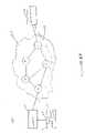
- FIG. 1depicts a packet communications system 100 that employs a diagnostic system an method in accordance with the principles of the present invention.
- a data source 102communicates with a data destination 104 by sending packets of data through a network of routers 106 .
- routers 106In this illustrative example only five routers A, B, C, D, and E, are shown.
- a packetmay travel from the source to the destination through a variety of paths.
- a packetmay travel from the source 102 to the destination 104 through routers A,B, and C; through routers A,D,B, and C, or through routers A,D,E, and C.
- a signaling path 108may wind through a variety of routers, and provides signaling information, such as “Off Hook”, “Answer”, for example, to source and destination.
- a diagnostic system 110 in accordance with the present inventionmay be located at a source 102 (as illustrated) or at other locations throughout the network, including the destination 104 , for example.
- the diagnostic systemincludes a controller 112 and an interface 114 to the source 102 and network.
- the controller 112may be configured to operate as a monitor, a packet source, and/or a call establishment mechanism.
- the interface 114provides access to the data packet transmission resources and signaling resources of the network.
- the diagnostic system 110may be connected, through the interface 114 , in series with or in parallel with the source 102 .
- the interface 114may be through a communications adapter 290 or a bus 230 , as described in the discussion related to FIG. 2 , for example.
- the diagnostic system 110may operate in a passive manner, detecting the establishment of a communications session, then injecting diagnostic packets into the data stream once the communications session has commenced.
- the diagnostic packetsmay be sent at any time during the communications session, that is, for example, before, interleaved with, or after data packets are sent.
- the diagnostic system 110may operate in an active mode, employing the signaling path 108 to establish a communications session, then proceeding to send diagnostic packets.
- the diagnostic system 110in addition to diagnostic packets, in an active mode, the diagnostic system 110 generates and sends data packets having the same characteristics as data packets that would otherwise be transmitted by the source 102 or destination 104 .
- the diagnostic systemwould generate packets having the same characteristics as those packets and send them during a communication session established by the diagnostic system 110 .
- the diagnostic systemwould also, after establishing the communications session, transmit diagnostic packets during the communications session.
- the diagnostic systemwould generate and send diagnostic packets during the communications session, before, interleaves with, or after the data packets.
- the diagnostic packetswould exhibit the same characteristics as the data packets.
- Each diagnostic packetelicits a response from a router along a path between the source 102 and destination 104 .
- the responses elicited by the diagnostic packetsare in the form of packets that include time stamps and the address of the router returning the packet.
- Diagnostic packetsmay be in the form of packets which cause a router to generate and return an “error packet” that includes the router's address and a time stamp.
- FIG. 1Bdepicts a system in which diagnostic elements are arranged in a peer-to-peer active testing configuration.
- FIG. 1Cdepicts a system in which a diagnostic element is arranged in a single point active testing mode.
- FIG. 1Ddepicts a system in which diagnostic elements are arranged in a peer-to-peer passive testing mode
- FIG. 1Edepicts a system in which a diagnostic element is arranged in a single point passive testing mode.
- FIG. 2illustrates the system architecture for a computer system 200 on which a controller in accordance with the principles of the present invention may be implemented.
- the exemplary computer system of FIG. 2is for descriptive purposes only. Although the description may refer to terms commonly used in describing particular computer systems, the description and concepts equally apply to other systems, including systems having architectures dissimilar to FIG. 2 .
- Computer system 200includes a central processing unit (CPU) 205 , which may be implemented with a conventional microprocessor, a random access memory (RAM) 210 for temporary storage of information, and a read only memory (ROM) 215 for permanent storage of information.
- CPUcentral processing unit
- RAMrandom access memory
- ROMread only memory
- a memory controller 220is provided for controlling RAM 210 .
- a bus 230interconnects the components of computer system 200 .
- a bus controller 225is provided for controlling bus 230 .
- An interrupt controller 235is used for receiving and processing various interrupt signals from the system components.
- Mass storagemay be provided by diskette 242 , CD ROM 247 , or hard drive 252 .
- Data and softwaremay be exchanged with computer system 200 via removable media such as diskette 242 and CD ROM 247 .
- Diskette 242is insertable into diskette drive 241 which is, in turn, connected to bus 230 by a controller 240 .
- CD ROM 247is insertable into CD ROM drive 246 which is, in turn, connected to bus 230 by controller 245 .
- Hard disc 252is part of a fixed disc drive 251 which is connected to bus 230 by controller 250 .
- User input to computer system 200may be provided by a number of devices.
- a keyboard 256 and mouse 257are connected to bus 230 by controller 255 .
- An audio transducer 296which may act as both a microphone and a speaker, is connected to bus 230 by audio controller 297 , as illustrated. It will be obvious to those reasonably skilled in the art that other input devices, such as a pen and/or tabloid may be connected to bus 230 and an appropriate controller and software, as required.
- DMA controller 260is provided for performing direct memory access to RAM 210 .
- a visual displayis generated by video controller 265 which controls video display 270 .
- Computer system 200also includes a communications adaptor 290 which allows the system to be interconnected to a local area network (LAN) or a wide area network (WAN), schematically illustrated by bus 291 and network 295 .
- An input interface 299operates in conjunction with an input device 293 to permit a user to send information, whether command and control, data, or other types of information, to the system 200 .
- the input device and interfacemay be any of a number of common interface devices, such as a joystick, a touch-pad, a touch-screen, a speech-recognition device, or other known input device.
- the interface 114 to the network and source 102may be an interface to the bus 230 , to the input interface 299 , or combinations thereof, for example.
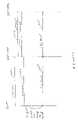
- FIG. 3provides an overview of the process whereby a communications session is established and diagnostic packets are utilized in accordance with the principles of the present invention.
- the source 102signals an “off hook” condition to the packet network 106 through the signaling path 108 .
- the packet networkpasses the “off hook” signal to the destination 104 .
- the destination 104returns and “Answer” signal through the signaling path 108 to the network 106 .
- the “Answer” signalis passed to the source 102 , thereby establishing a communications session. Once a connection session has been established in this manner, the source may begin transmitting data packets.
- a diagnostic system in accordance with the principles of the present inventionsends diagnostic packets during a communications session, as defined by the period between the “Answer” of step 4 and the termination of the session by an “on hook” condition established by either the source or destination in step 5 .
- a diagnostic packet 400such as may be employed by a diagnostic system in accordance with the principles of the present invention, includes a header 402 that contains components as depicted by the block diagram of FIG. 4 .
- Each header 402includes a field 404 that elicits a response from at least one router along a communications path from a source to a destination.
- the elicited responsesinclude a timestamp and the address of the router that returns the response packet.
- the length of the diagnostic packetwhich may be indicated by a header entry 406 is the same as data packets sent during a communications session.
- the data typeas indicated by a header entry 408 , is a valid entry for the type of data being transmitted during the communications session.
- FIG. 5Aillustrates the components of a real time protocol (RTP) diagnostic packet 500 in accordance with the principles of the present invention.
- the diagnostic packetincludes a header that includes a time to live (TTL) value 502 that is set to elicit an error response from a router along the path between the source and destination of a communications session.
- TTLtime to live
- a diagnostic packet sourcein accordance with the principles of the present invention creates a diagnostic packet having a TTL value that will be decremented as the packet traverses a path between the source and destination. The diagnostic packet source sets the TTL value so that the packet causes a router along the way to respond with a “time expired” error packet.
- Each time-expired error packetincludes a time stamp, and the address of the router sending the error packet.
- the diagnostic packet 500is of the same length as data packets being transmitted.
- a data type field 504is set to the same value as that of data packets being transmitted during the communications session.
- the data typemay indicate that the data is voice data or video data, for example.
- the differential services field 506is also set to the same value as that of the data being transmitted during the communications session. This field may allow policy-based preferential routing, giving higher priority to voice packets than to email packets, for example.
- the headeralso includes source 508 and destination 510 addresses. Diagnostic packets are indistinguishable from the regular, in-session, packets.
- FIG. 5Bis a block diagram that illustrates a response packet elicited by an RTP diagnostic packet in accordance with the principles of the present invention.
- the returned packetis an ICMP packet 512 that includes a type field 514 , a code field 516 , and a time stamp 518 .
- the type and code fieldsidentify the returned packet as an ICMP “time exceeded” or type 11 , error packet.
- the time stampmay be used by a diagnostic system in accordance with the principles of the present invention to determine latency and jitter during a communications session.
- the flow chart of FIG. 6depicts the process of determining the performance of a packet network in accordance with the principles of the present invention.
- the processbegins in step 600 then proceeds to step 602 where the diagnostic system either establishes or detects the establishment of a communications session between a source and a destination.
- a controllersuch as the controller 212 described in relation to the discussion of FIGS. 1 and 2 , may be configured to establish and/or detect such an establishment of a communications session, evidenced by the “Answer” of a destination, as described in the discussion related to FIG. 3 .
- the processproceeds to step 604 , where the diagnostic system determines the number of routers, or “hops”, between the source and destination.
- this informationmay be obtained from signaling information available through a signaling path, such as the path 108 described in relation to the discussion of FIG. 1 in a peer-to-peer active testing configuration, whereby a transmitting diagnostic element indicates to a receiving diagnostic element an initial TTL value and the receiving diagnostic element determines the number of hops from the difference between the originating and received TTL values.
- step 606the diagnostic system determines packet parameters, such as packet length and type of service, by examining a data packet that has been transmitted by a source. As described in the discussion of FIG. 4 , diagnostic packets produced by the diagnostic system match the length, data type, and differential services value, of the data packets communicated during a session. If the diagnostic system established, rather than detected, the establishment of the communications session, the diagnostic system produces both the “data” and diagnostic packets and ensures a match between length, data type, and differential services value of the diagnostic and data packets.
- packet parameterssuch as packet length and type of service
- step 608the diagnostic system sends diagnostic packets that elicit responses from every router along at least one path between the source and destination.
- the diagnostic systemmay employ packets having time to live (TTL) values that prompt routers along the path to return ICMP “time exceeded” error messages. Since the diagnostic system has determined the number of hops along the path between the source and destination in step 604 , the diagnostic system may generate and send diagnostic packets having all the TTL values required to elicit responses from all the routers along a communications path in any order. That is, unlike conventional systems, the diagnostic system needn't send packets that address high port numbers, with increasing TTL values, until the destination is reached.
- TTLtime to live
- step 610the diagnostic system analyzes the returned packets.
- latency and loss figuresmay be computed by transmitting a statistically significant number of diagnostic packets and examining the time stamps of returned packets, or, in the case of loss calculations, determining the number of diagnostic packets that don't receive responses.
- a jitter figuremay be associated with each router along the route by analyzing the time stamps of a statistically significant number of packets returned by each router. Loss, latency, and jitter may be computed for each router, as well as for the entire path.
- step 610the process proceeds to step 612 where a measure of service for each hop and/or for the entire path is developed and reported.
- the reportmay be made to a system monitor that can modify the network in order to improve service, for example.
- step 612the process proceeds to end in step 614 .
- a software implementation of the above described embodiment(s)may comprise a series of computer instructions either fixed on a tangible medium, such as a computer storage readable media, e.g. diskette, CD-ROM, ROM, or fixed disc, or computer readable transmission media transmittable to a computer system, via a modem or other interface device, such as communications adapter connected to the network over a medium.
- Mediumcan be either a tangible medium, including but not limited to, optical or analog communications lines, or may be implemented with wireless techniques, including but not limited to microwave, infrared or other transmission techniques.
- the series of computer instructionsembodies all or part of the functionality previously described herein with respect to the invention.
- Such computer instructionscan be written in a number of programming languages for use with many computer architectures, operating systems, or protocols. Further, such instructions may be stored using any memory technology, present or future, including, but not limited to, semiconductor, magnetic, optical or other memory devices, or transmitted using any communications technology, present or future, including but not limited to optical, infrared, microwave, or other transmission technologies. It is contemplated that such a computer program product may be distributed as a removable media with accompanying printed or electronic documentation, e.g., shrink wrapped software, preloaded with a computer system, e.g., on system ROM or fixed disc, or distribution from a server or electronic bulletin board over a network, e.g., the Internet or World Wide Web.
- a removable mediawith accompanying printed or electronic documentation, e.g., shrink wrapped software, preloaded with a computer system, e.g., on system ROM or fixed disc, or distribution from a server or electronic bulletin board over a network, e.g., the Internet or World Wide Web.
Landscapes
- Engineering & Computer Science (AREA)
- Computer Networks & Wireless Communication (AREA)
- Signal Processing (AREA)
- Data Exchanges In Wide-Area Networks (AREA)
Abstract
Description
Claims (63)
Priority Applications (2)
| Application Number | Priority Date | Filing Date | Title |
|---|---|---|---|
| US10/337,653US7454494B1 (en) | 2003-01-07 | 2003-01-07 | Apparatus and method for actively analyzing a data packet delivery path |
| US12/259,914US7840670B2 (en) | 2003-01-07 | 2008-10-28 | Apparatus and method for passively analyzing a data packet delivery path |
Applications Claiming Priority (1)
| Application Number | Priority Date | Filing Date | Title |
|---|---|---|---|
| US10/337,653US7454494B1 (en) | 2003-01-07 | 2003-01-07 | Apparatus and method for actively analyzing a data packet delivery path |
Related Child Applications (1)
| Application Number | Title | Priority Date | Filing Date |
|---|---|---|---|
| US12/259,914ContinuationUS7840670B2 (en) | 2003-01-07 | 2008-10-28 | Apparatus and method for passively analyzing a data packet delivery path |
Publications (1)
| Publication Number | Publication Date |
|---|---|
| US7454494B1true US7454494B1 (en) | 2008-11-18 |
Family
ID=40000841
Family Applications (2)
| Application Number | Title | Priority Date | Filing Date |
|---|---|---|---|
| US10/337,653Expired - LifetimeUS7454494B1 (en) | 2003-01-07 | 2003-01-07 | Apparatus and method for actively analyzing a data packet delivery path |
| US12/259,914Expired - LifetimeUS7840670B2 (en) | 2003-01-07 | 2008-10-28 | Apparatus and method for passively analyzing a data packet delivery path |
Family Applications After (1)
| Application Number | Title | Priority Date | Filing Date |
|---|---|---|---|
| US12/259,914Expired - LifetimeUS7840670B2 (en) | 2003-01-07 | 2008-10-28 | Apparatus and method for passively analyzing a data packet delivery path |
Country Status (1)
| Country | Link |
|---|---|
| US (2) | US7454494B1 (en) |
Cited By (22)
| Publication number | Priority date | Publication date | Assignee | Title |
|---|---|---|---|---|
| US20060126528A1 (en)* | 2004-12-13 | 2006-06-15 | Ramalho Michael A | Method and apparatus for discovering the incoming media path for an internet protocol media session |
| US20070248019A1 (en)* | 2004-12-28 | 2007-10-25 | Jian Feng | Method for Diagnosing the Router Which Supports Policy-Based Routing |
| US20080129464A1 (en)* | 2006-11-30 | 2008-06-05 | Jan Frey | Failure differentiation and recovery in distributed systems |
| US20080159165A1 (en)* | 2006-07-28 | 2008-07-03 | International Business Machines Corporation | Technique of Analyzing An Information System State |
| US20080310316A1 (en)* | 2007-06-18 | 2008-12-18 | Cisco Technology, Inc. | Surrogate Stream for Monitoring Realtime Media |
| US20090086642A1 (en)* | 2007-09-28 | 2009-04-02 | Cisco Technology, Inc. | High availability path audit |
| US20090089619A1 (en)* | 2007-09-27 | 2009-04-02 | Kung-Shiuh Huang | Automatic detection of functional defects and performance bottlenecks in network devices |
| US7599359B1 (en)* | 2004-12-14 | 2009-10-06 | At&T Corp. | Method and apparatus for monitoring end-to-end performance in a network |
| US20100137012A1 (en)* | 2006-04-20 | 2010-06-03 | Merten Gmbh & Co. Kg | Method for Installing a Radio System in a Building |
| US20100205481A1 (en)* | 2007-10-26 | 2010-08-12 | Huawei Technologies Co., Ltd. | Method and Apparatus for Detecting and Handling Peer Faults in Peer-to-Peer Network |
| US7817546B2 (en) | 2007-07-06 | 2010-10-19 | Cisco Technology, Inc. | Quasi RTP metrics for non-RTP media flows |
| WO2011015108A1 (en)* | 2009-08-07 | 2011-02-10 | 华为技术有限公司 | Voice loopback method, gateway and loopback node in voip network |
| US7936695B2 (en) | 2007-05-14 | 2011-05-03 | Cisco Technology, Inc. | Tunneling reports for real-time internet protocol media streams |
| US8023419B2 (en) | 2007-05-14 | 2011-09-20 | Cisco Technology, Inc. | Remote monitoring of real-time internet protocol media streams |
| US20120151043A1 (en)* | 2010-12-14 | 2012-06-14 | At&T Intellectual Property I, L.P. | System for Internet Scale Visualization and Detection of Performance Events |
| US8301982B2 (en) | 2009-11-18 | 2012-10-30 | Cisco Technology, Inc. | RTP-based loss recovery and quality monitoring for non-IP and raw-IP MPEG transport flows |
| US8819714B2 (en) | 2010-05-19 | 2014-08-26 | Cisco Technology, Inc. | Ratings and quality measurements for digital broadcast viewers |
| US8966551B2 (en) | 2007-11-01 | 2015-02-24 | Cisco Technology, Inc. | Locating points of interest using references to media frames within a packet flow |
| US9197857B2 (en) | 2004-09-24 | 2015-11-24 | Cisco Technology, Inc. | IP-based stream splicing with content-specific splice points |
| US9300562B2 (en) | 2012-08-20 | 2016-03-29 | Viavi Solutions Inc. | Validating network traffic policy |
| US20160191401A1 (en)* | 2014-12-31 | 2016-06-30 | Infineon Technologies Ag | Commmunication systems and methods having reduced frame duration |
| US12034588B1 (en)* | 2022-12-30 | 2024-07-09 | Juniper Networks, Inc. | Diagnostics reporting for wide area network assurance system |
Families Citing this family (22)
| Publication number | Priority date | Publication date | Assignee | Title |
|---|---|---|---|---|
| US7280486B2 (en)* | 2004-01-07 | 2007-10-09 | Cisco Technology, Inc. | Detection of forwarding problems for external prefixes |
| US8014322B2 (en)* | 2007-02-26 | 2011-09-06 | Cisco, Technology, Inc. | Diagnostic tool for troubleshooting multimedia streaming applications |
| US7843826B2 (en)* | 2008-11-07 | 2010-11-30 | Avaya Inc. | Automatic detection and re-configuration of priority status in telecommunications networks |
| US8730819B2 (en)* | 2009-10-14 | 2014-05-20 | Cisco Teechnology, Inc. | Flexible network measurement |
| EP2388947A1 (en)* | 2010-05-20 | 2011-11-23 | Thomson Licensing | Method of determination of transmission quality of a communication link and corresponding apparatus |
| US8903893B2 (en) | 2011-11-15 | 2014-12-02 | International Business Machines Corporation | Diagnostic heartbeating in a distributed data processing environment |
| US9244796B2 (en) | 2011-11-15 | 2016-01-26 | International Business Machines Corporation | Diagnostic heartbeat throttling |
| US8769089B2 (en) | 2011-11-15 | 2014-07-01 | International Business Machines Corporation | Distributed application using diagnostic heartbeating |
| US8874974B2 (en) | 2011-11-15 | 2014-10-28 | International Business Machines Corporation | Synchronizing a distributed communication system using diagnostic heartbeating |
| US8756453B2 (en) | 2011-11-15 | 2014-06-17 | International Business Machines Corporation | Communication system with diagnostic capabilities |
| US9521053B1 (en) | 2014-10-28 | 2016-12-13 | Amazon Technologies, Inc. | Providing diagnostic metrics for virtual connections over physical connections into a provider network |
| US9912566B1 (en) | 2015-07-20 | 2018-03-06 | Cisco Technology, Inc. | Method and apparatus for tracing paths in service function chains |
| GB2543838B (en) | 2015-10-30 | 2020-02-12 | Canon Kk | Estimation of network conditions of individual paths in a multi-path connection involving a device not aware of multi-path signaling |
| US10541900B2 (en)* | 2016-02-01 | 2020-01-21 | Arista Networks, Inc. | Hierarchical time stamping |
| US10333962B1 (en) | 2016-03-30 | 2019-06-25 | Amazon Technologies, Inc. | Correlating threat information across sources of distributed computing systems |
| US10079842B1 (en) | 2016-03-30 | 2018-09-18 | Amazon Technologies, Inc. | Transparent volume based intrusion detection |
| US10142290B1 (en) | 2016-03-30 | 2018-11-27 | Amazon Technologies, Inc. | Host-based firewall for distributed computer systems |
| US10178119B1 (en) | 2016-03-30 | 2019-01-08 | Amazon Technologies, Inc. | Correlating threat information across multiple levels of distributed computing systems |
| US10148675B1 (en) | 2016-03-30 | 2018-12-04 | Amazon Technologies, Inc. | Block-level forensics for distributed computing systems |
| US10320750B1 (en)* | 2016-03-30 | 2019-06-11 | Amazon Technologies, Inc. | Source specific network scanning in a distributed environment |
| CN108259261B (en) | 2017-03-31 | 2020-02-11 | 新华三技术有限公司 | Path detection method and device |
| CN108259335B (en) | 2017-03-31 | 2020-09-08 | 新华三技术有限公司 | Path detection method and device |
Citations (37)
| Publication number | Priority date | Publication date | Assignee | Title |
|---|---|---|---|---|
| US4380029A (en) | 1981-03-13 | 1983-04-12 | Bti Computer Systems | Data recording format and method and apparatus for producing same |
| US4569042A (en) | 1983-12-23 | 1986-02-04 | At&T Bell Laboratories | Time measurements in a transmission path |
| US5271000A (en)* | 1991-03-22 | 1993-12-14 | International Business Machines Corporation | Method and apparatus for testing and evaluation of distributed networks |
| US5309428A (en) | 1993-01-11 | 1994-05-03 | John Fluke Mfg. Co., Inc. | Token ring local area network testing apparatus for phase jitter testing |
| US5315580A (en)* | 1990-09-28 | 1994-05-24 | Hewlett-Packard Company | Network monitoring device and system |
| US5337308A (en) | 1992-01-27 | 1994-08-09 | Nec Corporation | Low delay ATM switching system using idle cells stamped with reference time |
| US5539659A (en)* | 1993-02-22 | 1996-07-23 | Hewlett-Packard Company | Network analysis method |
| US5615262A (en) | 1993-12-03 | 1997-03-25 | Thomson-Csf | Device for securing an information system used in microcomputers |
| US5627766A (en)* | 1994-02-08 | 1997-05-06 | International Business Machines Corporation | Performance and status monitoring in a computer network |
| US5675741A (en)* | 1994-10-25 | 1997-10-07 | Cabletron Systems, Inc. | Method and apparatus for determining a communications path between two nodes in an Internet Protocol (IP) network |
| US5822317A (en) | 1995-09-04 | 1998-10-13 | Hitachi, Ltd. | Packet multiplexing transmission apparatus |
| US5892924A (en) | 1996-01-31 | 1999-04-06 | Ipsilon Networks, Inc. | Method and apparatus for dynamically shifting between routing and switching packets in a transmission network |
| US5923902A (en) | 1996-02-20 | 1999-07-13 | Yamaha Corporation | System for synchronizing a plurality of nodes to concurrently generate output signals by adjusting relative timelags based on a maximum estimated timelag |
| US5953483A (en) | 1995-03-28 | 1999-09-14 | U.S. Philips Corporation | Apparatus for recording and reproducing an information signal comprising packets that may occur irregularly as a function of time in a serial datastream of the information signal, and a record carrier carrying the information signal |
| US5966387A (en) | 1995-09-25 | 1999-10-12 | Bell Atlantic Network Services, Inc. | Apparatus and method for correcting jitter in data packets |
| US6006270A (en) | 1996-07-18 | 1999-12-21 | Nec Corporation | Communication system with time stamp controller for regulating datatransmission rate |
| US6104729A (en) | 1996-09-16 | 2000-08-15 | Telefonaktiebolaget Lm Ericsson | Method and apparatus for synchronization of time stamping |
| US20020105911A1 (en)* | 1998-11-24 | 2002-08-08 | Parag Pruthi | Apparatus and method for collecting and analyzing communications data |
| US20020120727A1 (en)* | 2000-12-21 | 2002-08-29 | Robert Curley | Method and apparatus for providing measurement, and utilization of, network latency in transaction-based protocols |
| US6445681B1 (en) | 1999-09-15 | 2002-09-03 | Vocaltec Communications Ltd. | Method for measuring delay parameters in a network |
| US6480898B1 (en)* | 1999-09-10 | 2002-11-12 | Array Telecom Corporation | System, method, and computer program product for managing a carrier exchange network |
| US6515967B1 (en)* | 1998-06-30 | 2003-02-04 | Cisco Technology, Inc. | Method and apparatus for detecting a fault in a multicast routing infrastructure |
| US20030031126A1 (en)* | 2001-03-12 | 2003-02-13 | Mayweather Derek T. | Bandwidth reservation reuse in dynamically allocated ring protection and restoration technique |
| US20030046388A1 (en)* | 2001-09-06 | 2003-03-06 | Milliken Walter Clark | Systems and methods for network performance measurement using packet signature collection |
| US20030086425A1 (en)* | 2001-10-15 | 2003-05-08 | Bearden Mark J. | Network traffic generation and monitoring systems and methods for their use in testing frameworks for determining suitability of a network for target applications |
| US20030093513A1 (en)* | 2001-09-11 | 2003-05-15 | Hicks Jeffrey Todd | Methods, systems and computer program products for packetized voice network evaluation |
| US6621800B1 (en)* | 2000-01-24 | 2003-09-16 | Avaya Technology Corp. | Message monitor application concept and implementation |
| US20030227878A1 (en)* | 2002-06-07 | 2003-12-11 | Krumm-Heller Alexander Michael | Apparatus and method for automatically and dynamically reconfiguring network provisioning |
| US6665317B1 (en) | 1999-10-29 | 2003-12-16 | Array Telecom Corporation | Method, system, and computer program product for managing jitter |
| US6680955B1 (en) | 1999-08-20 | 2004-01-20 | Nokia Networks Oy | Technique for compressing a header field in a data packet |
| US6721272B1 (en) | 1999-10-08 | 2004-04-13 | Cisco Technology, Inc. | Method and apparatus for generating an RSVP message for a non-RSVP-enabled network device |
| US20040073641A1 (en)* | 2002-09-30 | 2004-04-15 | Muneyb Minhazuddin | Instantaneous user initiation voice quality feedback |
| US6785237B1 (en) | 2000-03-31 | 2004-08-31 | Networks Associates Technology, Inc. | Method and system for passive quality of service monitoring of a network |
| US20050123003A1 (en) | 1999-07-01 | 2005-06-09 | Cisco Technology, Inc. | Method and apparatus for measuring network data packet delay, jitter and loss |
| US6944673B2 (en)* | 2000-09-08 | 2005-09-13 | The Regents Of The University Of Michigan | Method and system for profiling network flows at a measurement point within a computer network |
| US6990124B1 (en)* | 1998-03-24 | 2006-01-24 | Nortel Networks Limited | SS7-Internet gateway access signaling protocol |
| US7072305B1 (en)* | 1999-10-29 | 2006-07-04 | Applied Digital Access, Inc. | Method and apparatus for analyzing a communications network link |
Family Cites Families (5)
| Publication number | Priority date | Publication date | Assignee | Title |
|---|---|---|---|---|
| US6366563B1 (en)* | 1999-12-22 | 2002-04-02 | Mci Worldcom, Inc. | Method, computer program product, and apparatus for collecting service level agreement statistics in a communication network |
| US6975629B2 (en) | 2000-03-22 | 2005-12-13 | Texas Instruments Incorporated | Processing packets based on deadline intervals |
| US20020193999A1 (en)* | 2001-06-14 | 2002-12-19 | Michael Keane | Measuring speech quality over a communications network |
| US7127508B2 (en)* | 2001-12-19 | 2006-10-24 | Tropic Networks Inc. | Method and system of measuring latency and packet loss in a network by using probe packets |
| US20040073690A1 (en)* | 2002-09-30 | 2004-04-15 | Neil Hepworth | Voice over IP endpoint call admission |
- 2003
- 2003-01-07USUS10/337,653patent/US7454494B1/ennot_activeExpired - Lifetime
- 2008
- 2008-10-28USUS12/259,914patent/US7840670B2/ennot_activeExpired - Lifetime
Patent Citations (37)
| Publication number | Priority date | Publication date | Assignee | Title |
|---|---|---|---|---|
| US4380029A (en) | 1981-03-13 | 1983-04-12 | Bti Computer Systems | Data recording format and method and apparatus for producing same |
| US4569042A (en) | 1983-12-23 | 1986-02-04 | At&T Bell Laboratories | Time measurements in a transmission path |
| US5315580A (en)* | 1990-09-28 | 1994-05-24 | Hewlett-Packard Company | Network monitoring device and system |
| US5271000A (en)* | 1991-03-22 | 1993-12-14 | International Business Machines Corporation | Method and apparatus for testing and evaluation of distributed networks |
| US5337308A (en) | 1992-01-27 | 1994-08-09 | Nec Corporation | Low delay ATM switching system using idle cells stamped with reference time |
| US5309428A (en) | 1993-01-11 | 1994-05-03 | John Fluke Mfg. Co., Inc. | Token ring local area network testing apparatus for phase jitter testing |
| US5539659A (en)* | 1993-02-22 | 1996-07-23 | Hewlett-Packard Company | Network analysis method |
| US5615262A (en) | 1993-12-03 | 1997-03-25 | Thomson-Csf | Device for securing an information system used in microcomputers |
| US5627766A (en)* | 1994-02-08 | 1997-05-06 | International Business Machines Corporation | Performance and status monitoring in a computer network |
| US5675741A (en)* | 1994-10-25 | 1997-10-07 | Cabletron Systems, Inc. | Method and apparatus for determining a communications path between two nodes in an Internet Protocol (IP) network |
| US5953483A (en) | 1995-03-28 | 1999-09-14 | U.S. Philips Corporation | Apparatus for recording and reproducing an information signal comprising packets that may occur irregularly as a function of time in a serial datastream of the information signal, and a record carrier carrying the information signal |
| US5822317A (en) | 1995-09-04 | 1998-10-13 | Hitachi, Ltd. | Packet multiplexing transmission apparatus |
| US5966387A (en) | 1995-09-25 | 1999-10-12 | Bell Atlantic Network Services, Inc. | Apparatus and method for correcting jitter in data packets |
| US5892924A (en) | 1996-01-31 | 1999-04-06 | Ipsilon Networks, Inc. | Method and apparatus for dynamically shifting between routing and switching packets in a transmission network |
| US5923902A (en) | 1996-02-20 | 1999-07-13 | Yamaha Corporation | System for synchronizing a plurality of nodes to concurrently generate output signals by adjusting relative timelags based on a maximum estimated timelag |
| US6006270A (en) | 1996-07-18 | 1999-12-21 | Nec Corporation | Communication system with time stamp controller for regulating datatransmission rate |
| US6104729A (en) | 1996-09-16 | 2000-08-15 | Telefonaktiebolaget Lm Ericsson | Method and apparatus for synchronization of time stamping |
| US6990124B1 (en)* | 1998-03-24 | 2006-01-24 | Nortel Networks Limited | SS7-Internet gateway access signaling protocol |
| US6515967B1 (en)* | 1998-06-30 | 2003-02-04 | Cisco Technology, Inc. | Method and apparatus for detecting a fault in a multicast routing infrastructure |
| US20020105911A1 (en)* | 1998-11-24 | 2002-08-08 | Parag Pruthi | Apparatus and method for collecting and analyzing communications data |
| US20050123003A1 (en) | 1999-07-01 | 2005-06-09 | Cisco Technology, Inc. | Method and apparatus for measuring network data packet delay, jitter and loss |
| US6680955B1 (en) | 1999-08-20 | 2004-01-20 | Nokia Networks Oy | Technique for compressing a header field in a data packet |
| US6480898B1 (en)* | 1999-09-10 | 2002-11-12 | Array Telecom Corporation | System, method, and computer program product for managing a carrier exchange network |
| US6445681B1 (en) | 1999-09-15 | 2002-09-03 | Vocaltec Communications Ltd. | Method for measuring delay parameters in a network |
| US6721272B1 (en) | 1999-10-08 | 2004-04-13 | Cisco Technology, Inc. | Method and apparatus for generating an RSVP message for a non-RSVP-enabled network device |
| US7072305B1 (en)* | 1999-10-29 | 2006-07-04 | Applied Digital Access, Inc. | Method and apparatus for analyzing a communications network link |
| US6665317B1 (en) | 1999-10-29 | 2003-12-16 | Array Telecom Corporation | Method, system, and computer program product for managing jitter |
| US6621800B1 (en)* | 2000-01-24 | 2003-09-16 | Avaya Technology Corp. | Message monitor application concept and implementation |
| US6785237B1 (en) | 2000-03-31 | 2004-08-31 | Networks Associates Technology, Inc. | Method and system for passive quality of service monitoring of a network |
| US6944673B2 (en)* | 2000-09-08 | 2005-09-13 | The Regents Of The University Of Michigan | Method and system for profiling network flows at a measurement point within a computer network |
| US20020120727A1 (en)* | 2000-12-21 | 2002-08-29 | Robert Curley | Method and apparatus for providing measurement, and utilization of, network latency in transaction-based protocols |
| US20030031126A1 (en)* | 2001-03-12 | 2003-02-13 | Mayweather Derek T. | Bandwidth reservation reuse in dynamically allocated ring protection and restoration technique |
| US20030046388A1 (en)* | 2001-09-06 | 2003-03-06 | Milliken Walter Clark | Systems and methods for network performance measurement using packet signature collection |
| US20030093513A1 (en)* | 2001-09-11 | 2003-05-15 | Hicks Jeffrey Todd | Methods, systems and computer program products for packetized voice network evaluation |
| US20030086425A1 (en)* | 2001-10-15 | 2003-05-08 | Bearden Mark J. | Network traffic generation and monitoring systems and methods for their use in testing frameworks for determining suitability of a network for target applications |
| US20030227878A1 (en)* | 2002-06-07 | 2003-12-11 | Krumm-Heller Alexander Michael | Apparatus and method for automatically and dynamically reconfiguring network provisioning |
| US20040073641A1 (en)* | 2002-09-30 | 2004-04-15 | Muneyb Minhazuddin | Instantaneous user initiation voice quality feedback |
Non-Patent Citations (3)
| Title |
|---|
| Baker, F. "Requirements for IP Version 4 Routers". RFC 1812, Jun. 1995. pp. 52-62.* |
| Dr. AmirAtai and Dr. James Gordon, "Architectural Solutions to Internet Congestion Based on SS7 and Intelligent Network Capabilities," A Bellcore White Paper, 1997, 18 pages.* |
| Shulzrinne et al. "RTP: A Transport Protocol for Real-Time Applications". Jan. 1996, pp. 3-6.* |
Cited By (39)
| Publication number | Priority date | Publication date | Assignee | Title |
|---|---|---|---|---|
| US9197857B2 (en) | 2004-09-24 | 2015-11-24 | Cisco Technology, Inc. | IP-based stream splicing with content-specific splice points |
| US20060126528A1 (en)* | 2004-12-13 | 2006-06-15 | Ramalho Michael A | Method and apparatus for discovering the incoming media path for an internet protocol media session |
| US7633879B2 (en)* | 2004-12-13 | 2009-12-15 | Cisco Technology, Inc. | Method and apparatus for discovering the incoming media path for an internet protocol media session |
| US7599359B1 (en)* | 2004-12-14 | 2009-10-06 | At&T Corp. | Method and apparatus for monitoring end-to-end performance in a network |
| US20070248019A1 (en)* | 2004-12-28 | 2007-10-25 | Jian Feng | Method for Diagnosing the Router Which Supports Policy-Based Routing |
| US8223761B2 (en)* | 2004-12-28 | 2012-07-17 | Zte Corporation | Method for diagnosing the router which supports policy-based routing |
| US8219102B2 (en)* | 2006-04-20 | 2012-07-10 | Merten Gmbh & Co. Kg | Method for installing a radio system in a building |
| US20100137012A1 (en)* | 2006-04-20 | 2010-06-03 | Merten Gmbh & Co. Kg | Method for Installing a Radio System in a Building |
| US7752307B2 (en)* | 2006-07-28 | 2010-07-06 | International Business Machines Corporation | Technique of analyzing an information system state |
| US20080159165A1 (en)* | 2006-07-28 | 2008-07-03 | International Business Machines Corporation | Technique of Analyzing An Information System State |
| US8166156B2 (en)* | 2006-11-30 | 2012-04-24 | Nokia Corporation | Failure differentiation and recovery in distributed systems |
| US20080129464A1 (en)* | 2006-11-30 | 2008-06-05 | Jan Frey | Failure differentiation and recovery in distributed systems |
| US8867385B2 (en) | 2007-05-14 | 2014-10-21 | Cisco Technology, Inc. | Tunneling reports for real-time Internet Protocol media streams |
| US7936695B2 (en) | 2007-05-14 | 2011-05-03 | Cisco Technology, Inc. | Tunneling reports for real-time internet protocol media streams |
| US8023419B2 (en) | 2007-05-14 | 2011-09-20 | Cisco Technology, Inc. | Remote monitoring of real-time internet protocol media streams |
| US7835406B2 (en) | 2007-06-18 | 2010-11-16 | Cisco Technology, Inc. | Surrogate stream for monitoring realtime media |
| US20080310316A1 (en)* | 2007-06-18 | 2008-12-18 | Cisco Technology, Inc. | Surrogate Stream for Monitoring Realtime Media |
| US7817546B2 (en) | 2007-07-06 | 2010-10-19 | Cisco Technology, Inc. | Quasi RTP metrics for non-RTP media flows |
| US7840841B2 (en)* | 2007-09-27 | 2010-11-23 | Cisco Technology, Inc. | Automatic detection of functional defects and performance bottlenecks in network devices |
| US20090089619A1 (en)* | 2007-09-27 | 2009-04-02 | Kung-Shiuh Huang | Automatic detection of functional defects and performance bottlenecks in network devices |
| US20090086642A1 (en)* | 2007-09-28 | 2009-04-02 | Cisco Technology, Inc. | High availability path audit |
| US8381013B2 (en)* | 2007-10-26 | 2013-02-19 | Huawei Technologies Co., Ltd. | Method and apparatus for detecting and handling peer faults in peer-to-peer network |
| US20100205481A1 (en)* | 2007-10-26 | 2010-08-12 | Huawei Technologies Co., Ltd. | Method and Apparatus for Detecting and Handling Peer Faults in Peer-to-Peer Network |
| US9762640B2 (en) | 2007-11-01 | 2017-09-12 | Cisco Technology, Inc. | Locating points of interest using references to media frames within a packet flow |
| US8966551B2 (en) | 2007-11-01 | 2015-02-24 | Cisco Technology, Inc. | Locating points of interest using references to media frames within a packet flow |
| US9118748B2 (en) | 2009-08-07 | 2015-08-25 | Huawei Technologies Co., Ltd. | Voice loopback method, gateway and loopback node in VoIP network |
| WO2011015108A1 (en)* | 2009-08-07 | 2011-02-10 | 华为技术有限公司 | Voice loopback method, gateway and loopback node in voip network |
| US8301982B2 (en) | 2009-11-18 | 2012-10-30 | Cisco Technology, Inc. | RTP-based loss recovery and quality monitoring for non-IP and raw-IP MPEG transport flows |
| US8819714B2 (en) | 2010-05-19 | 2014-08-26 | Cisco Technology, Inc. | Ratings and quality measurements for digital broadcast viewers |
| US8671183B2 (en)* | 2010-12-14 | 2014-03-11 | At&T Intellectual Property I, L.P. | System for internet scale visualization and detection of performance events |
| US20120151043A1 (en)* | 2010-12-14 | 2012-06-14 | At&T Intellectual Property I, L.P. | System for Internet Scale Visualization and Detection of Performance Events |
| US9300562B2 (en) | 2012-08-20 | 2016-03-29 | Viavi Solutions Inc. | Validating network traffic policy |
| US20160191401A1 (en)* | 2014-12-31 | 2016-06-30 | Infineon Technologies Ag | Commmunication systems and methods having reduced frame duration |
| US9654407B2 (en)* | 2014-12-31 | 2017-05-16 | Infineon Technologies Ag | Communication systems and methods having reduced frame duration |
| US10178039B2 (en) | 2014-12-31 | 2019-01-08 | Infineon Technologies Ag | Communication systems and methods having reduced frame duration |
| US10225202B2 (en) | 2014-12-31 | 2019-03-05 | Infineon Technologies Ag | Communication systems and methods having reduced frame duration |
| US12034588B1 (en)* | 2022-12-30 | 2024-07-09 | Juniper Networks, Inc. | Diagnostics reporting for wide area network assurance system |
| US20240356797A1 (en)* | 2022-12-30 | 2024-10-24 | Juniper Networks, Inc. | Diagnostics reporting for wide area network assurance system |
| US12362990B2 (en)* | 2022-12-30 | 2025-07-15 | Juniper Networks, Inc. | Diagnostics reporting for wide area network assurance system |
Also Published As
| Publication number | Publication date |
|---|---|
| US20090086645A1 (en) | 2009-04-02 |
| US7840670B2 (en) | 2010-11-23 |
Similar Documents
| Publication | Publication Date | Title |
|---|---|---|
| US7454494B1 (en) | Apparatus and method for actively analyzing a data packet delivery path | |
| JP5719449B2 (en) | System and method for measuring available capacity and narrow link capacity of an IP path from a single endpoint | |
| US7596096B2 (en) | Method and apparatus for providing trace route and timing information for media streams | |
| US7496044B1 (en) | Method and apparatus for analyzing a media path for an internet protocol (IP) media session | |
| US8219675B2 (en) | System and method for correlating IP flows across network address translation firewalls | |
| EP2001165B1 (en) | Method and system for measuring network performance | |
| US7519006B1 (en) | Method and apparatus for measuring one-way delay at arbitrary points in network | |
| US7738383B2 (en) | Traceroute using address request messages | |
| US8270309B1 (en) | Systems for monitoring delivery performance of a packet flow between reference nodes | |
| US20100150005A1 (en) | System and method for determination of routing information in a network | |
| CN101552703A (en) | A method and device to measure service quality parameters and a method and device to judge service quality | |
| US7843826B2 (en) | Automatic detection and re-configuration of priority status in telecommunications networks | |
| US7881214B2 (en) | Method for performing remote testing of network using IP measurement protocol packets | |
| US20070160050A1 (en) | Diagnostic mechanism for Layer 2 and Layer 3 networks | |
| KR101467137B1 (en) | In-service throughput testing in distributed router/switch architectures | |
| JP2015535669A (en) | Monitoring encrypted sessions | |
| US7894355B2 (en) | Method for enabling non-predetermined testing of network using IP measurement protocol packets | |
| JP2008048131A (en) | P2P traffic monitoring control apparatus and method | |
| Morton | Round-trip packet loss metrics | |
| US20040090921A1 (en) | Method and apparatus for testing an IP network | |
| US20040098479A1 (en) | Method for using different packet type and port options values in an IP measurement protocol packet from those used to process the packet | |
| US20040148386A1 (en) | Dynamic CC/PP-based profile generation framework for network conditions assessment | |
| US8593997B2 (en) | Full duplex/half duplex mismatch detecting method and full duplex/half duplex mismatch detecting apparatus applicable with the method | |
| US7336619B2 (en) | Method for converting an IP measurement protocol packet to a data packet | |
| CN110048913B (en) | BFD-based method for realizing NAT traversal bidirectional detection processing |
Legal Events
| Date | Code | Title | Description |
|---|---|---|---|
| AS | Assignment | Owner name:BRIX NETWORKS, INC., MASSACHUSETTS Free format text:ASSIGNMENT OF ASSIGNORS INTEREST;ASSIGNORS:HEDAYAT, KAYNAM;PYRIK, DANIEL;REEL/FRAME:013646/0174 Effective date:20021230 | |
| AS | Assignment | Owner name:HORIZON TECHNOLOGY FUNDING COMPANY LLC, CONNECTICU Free format text:SECURITY AGREEMENT;ASSIGNOR:BRIX NETWORKS, INC.;REEL/FRAME:019055/0173 Effective date:20070309 | |
| AS | Assignment | Owner name:HORIZON TECHNOLOGY FUNDING COMPANY LLC, CONNECTICU Free format text:RELEASE;ASSIGNOR:BRIX NETWORKS, INC.;REEL/FRAME:021050/0127 Effective date:20080422 | |
| STCF | Information on status: patent grant | Free format text:PATENTED CASE | |
| AS | Assignment | Owner name:EXFO SERVICE ASSURANCE INC., MASSACHUSETTS Free format text:MERGER;ASSIGNOR:BRIX NETWORKS, INC.;REEL/FRAME:021805/0170 Effective date:20080422 | |
| FEPP | Fee payment procedure | Free format text:PAYOR NUMBER ASSIGNED (ORIGINAL EVENT CODE: ASPN); ENTITY STATUS OF PATENT OWNER: LARGE ENTITY | |
| FEPP | Fee payment procedure | Free format text:PAYER NUMBER DE-ASSIGNED (ORIGINAL EVENT CODE: RMPN); ENTITY STATUS OF PATENT OWNER: LARGE ENTITY Free format text:PAYOR NUMBER ASSIGNED (ORIGINAL EVENT CODE: ASPN); ENTITY STATUS OF PATENT OWNER: LARGE ENTITY | |
| FPAY | Fee payment | Year of fee payment:4 | |
| FPAY | Fee payment | Year of fee payment:8 | |
| AS | Assignment | Owner name:EXFO INC., CANADA Free format text:ASSIGNMENT OF ASSIGNORS INTEREST;ASSIGNOR:EXFO SERVICE ASSURANCE INC.;REEL/FRAME:048394/0620 Effective date:20181201 | |
| MAFP | Maintenance fee payment | Free format text:PAYMENT OF MAINTENANCE FEE, 12TH YEAR, LARGE ENTITY (ORIGINAL EVENT CODE: M1553); ENTITY STATUS OF PATENT OWNER: LARGE ENTITY Year of fee payment:12 | |
| AS | Assignment | Owner name:NATIONAL BANK OF CANADA, CANADA Free format text:SECURITY INTEREST;ASSIGNORS:EXFO INC. (A CORPORATION RESULTING FROM THE AMALGAMATION OF 11172239 CANADA INC. AND EXFO INC.);ONTOLOGY-PARTNERS LIMITED;REEL/FRAME:072338/0500 Effective date:20210917 |