US7454222B2 - Apparatus and method for controlling wireless communication signals - Google Patents
Apparatus and method for controlling wireless communication signalsDownload PDFInfo
- Publication number
- US7454222B2 US7454222B2US09/990,349US99034901AUS7454222B2US 7454222 B2US7454222 B2US 7454222B2US 99034901 AUS99034901 AUS 99034901AUS 7454222 B2US7454222 B2US 7454222B2
- Authority
- US
- United States
- Prior art keywords
- signal
- data
- transmitter
- wireless
- power
- Prior art date
- Legal status (The legal status is an assumption and is not a legal conclusion. Google has not performed a legal analysis and makes no representation as to the accuracy of the status listed.)
- Expired - Lifetime, expires
Links
Images


Classifications
- H—ELECTRICITY
- H04—ELECTRIC COMMUNICATION TECHNIQUE
- H04L—TRANSMISSION OF DIGITAL INFORMATION, e.g. TELEGRAPHIC COMMUNICATION
- H04L1/00—Arrangements for detecting or preventing errors in the information received
- H04L1/0001—Systems modifying transmission characteristics according to link quality, e.g. power backoff
- H04L1/0002—Systems modifying transmission characteristics according to link quality, e.g. power backoff by adapting the transmission rate
- H04L1/0003—Systems modifying transmission characteristics according to link quality, e.g. power backoff by adapting the transmission rate by switching between different modulation schemes
- H—ELECTRICITY
- H04—ELECTRIC COMMUNICATION TECHNIQUE
- H04L—TRANSMISSION OF DIGITAL INFORMATION, e.g. TELEGRAPHIC COMMUNICATION
- H04L1/00—Arrangements for detecting or preventing errors in the information received
- H04L1/0001—Systems modifying transmission characteristics according to link quality, e.g. power backoff
- H04L1/0009—Systems modifying transmission characteristics according to link quality, e.g. power backoff by adapting the channel coding
- H—ELECTRICITY
- H04—ELECTRIC COMMUNICATION TECHNIQUE
- H04L—TRANSMISSION OF DIGITAL INFORMATION, e.g. TELEGRAPHIC COMMUNICATION
- H04L27/00—Modulated-carrier systems
- H04L27/0008—Modulated-carrier systems arrangements for allowing a transmitter or receiver to use more than one type of modulation
Definitions
- Another methodis using high order modulation such as Quadrature Amplitude Modulation (QAM) and high efficiency coding schemes such as Turbo code [IEEE802.16.1 Standard]. These methods can both be considered as time domain methods.
- QAMQuadrature Amplitude Modulation
- Turbo codeIEEE802.16.1 Standard
- SNRSignal to Noise Ratio
- a transmitter with higher transmitting power and a receiver with a lower noise figureare needed.
- PALinear Power Amplifier
- CPECustomer Premise Equipment
- PLLPhase Locked Loop
- FECForward Error Coding
- This methodis arranged on the evolution path of the Othogononal Frequency Division Multiple Access (OFDM). But the price of radio and antenna will prevent such a scheme from being deployed.
- OFDMOrthogonal Frequency Division Multiple Access
- An example of a system which involves lower layer hardware assisting higher layer real time software processing, and vice versais an optical device, which is able to directly process transport layer Internet Protocol (IP) headers without intervention of electrical signals at all.
- IPInternet Protocol
- IPInternet Protocol
- ATMAsynchronous Transfer Mode
- TCPTransmission Control Protocol
- ABRAvailable Bit Rate
- Broadband Wireless Access (BWA) servicesare commonly being deployed with Multi-channel Multi-point Distribution System (MMDS) or Local Multi-point Distribution System (LMDS) methods [IEEE Computer July 2000 by Sixto Ortiz Jr.].
- MMDSMulti-channel Multi-point Distribution System
- LMDSLocal Multi-point Distribution System
- the microwave frequency employedis around Ka band, i.e. 11 GHZ to 60 GHz. At this frequency range, rain causes severe attenuation of the signal.
- the rain margin for some radioscan be set as high as 25 dB—and it is only used once in a while (53 minutes downtime per year to meet 99.99% availability).
- the automatic Power Control (APC)is usually controlled by a rain event, i.e. when there is rain on the radio signal path between the CPE and the base station, the power at the transmitter is increased to compensate the rain attenuation.
- an apparatus for generating a signal for wireless transmissioncomprising signal generating means for receiving data and generating a signal containing received data for wireless transmission, and control means for controlling the data carrying capacity of said signal.
- the capacity of the communication channelmay be increased in response to the level of received data for wireless transmission.
- the power level of the communicationmay also be increased to facilitate transmission at the higher capacity.
- thisenables congestion or potential congestion at the transmitter to be alleviated and handed over to the receiver side of the network.
- the receiver side of the networkcomprises a base station, for example connected to a public switched network, for example, by a high speed transmission system such as may be provided by an optical fiber based system
- the receiver endshould be able to handle the additional traffic.
- This techniquemay advantageously take advantage of the additional power available at the power amplifier which is required to compensate for rain fade or other attenuation to maintain the communication link in adverse conditions.
- the capacity of the communication channelmay be reduced in order to render the channel more resilient to interference or attenuation caused by adverse conditions, thereby increasing the availability of the communication link over existing systems.
- the transmittermay be adapted to reduce its power level in response to a low level of incoming data in order to reduce the communication channel's potential to interfere with another communication channel, thereby allowing the other communication channel to increase its capacity throughput to alleviate its own congestion.
- the transmittermay transmit an indication of its ability to lower the power level of its transmission signal to a controller which can then inform other transmitters of this condition so that one or more transmitters may increase the capacity of their transmission channels.
- an apparatus for generating a signal for wireless transmissioncomprising signal generating means for receiving data and generating a signal containing received data for wireless transmission, monitoring means for monitoring the quantity of data supplied to said signal generating means for wireless transmission, and control means for controlling the power of the generated wireless signal in response to said monitored quantity of data for wireless transmission.
- a transmitterfor generating and transmitting a wireless communication signal
- the transmitterincluding signal control means for varying the power of the communication signal and limiting means for limiting the control means to control the power to reduce or substantially prevent interference by said wireless communication signal of a second wireless communication signal from another transmitter.
- a transmitter for generating a communication signal for wireless transmissioncomprising monitoring means for monitoring a quality of said wireless communication signal and capacity control means for controlling the data carrying capacity of said wireless communication signal in response to said monitored quality.
- a controller for controlling the operation of a wireless transmitter in a wireless communication network containing a plurality of wireless transmitterscomprising monitoring means for monitoring interference of a communication channel associated with a wireless transceiver by a wireless signal from another wireless transmitter, signal generating means for generating a signal indicative of interference, and transmitting means for transmitting said interference indicating signal to the transmitter transmitting the wireless signal causing the interferences, to control the level of interference.
- a controllerfor controlling the operation of a wireless transmitter in a wireless communication network containing a plurality of wireless transmitters, comprising monitoring means for monitoring a signal indicative of a power level of a wireless communication signal transmitted by a transmitter, comparing means for comparing the power level with a predetermined value, and transmitting means for transmitting a signal to said transmitter in response to said comparison indicative of the result of said comparison.
- a controller for controlling the operation of a wireless transmitter in a wireless communication network having a plurality of wireless transmitterscomprising receiving means for receiving a signal indicative of a power level for a wireless communication signal from a transmitter in said network, and transmitting means for transmitting a signal in response to the received signal to another transmitter in said network for enabling said transmitter to increase the power level of its wireless transmission signal.
- a method of generating a signal carrying data for wireless transmissioncomprising receiving data for wireless transmission, monitoring a parameter indicative of the quantity of received data and varying the rate at which data is included in said signal in response to said monitored parameter.
- a method of generating a signal for carrying data for wireless transmissioncomprising monitoring a parameter indicative of a quality of said wireless signal, comparing said quality with predetermined value and decreasing the capacity of the wireless signal if said parameter falls below a predetermined value.
- a method of controlling a transmitter in a wireless communication network containing a plurality of transmitterscomprising monitoring interference of a wireless communication channel associated with a transmitter in said network by a second wireless communication channel associated with another transmitter in said network and in response to determining interference, transmitting a signal to the transmitter causing said interference to reduce the power level of its wireless transmission channel.
- a method of determining an acceptable level of transmission power for each of a plurality of transmitters in a wireless communication networkcomprising the steps of increasing the transmission power of each transmitter in turn, monitoring interference of a communication channel associated with at least one of the other transmitters and determining an acceptable level of transmission power for each transmitter based on the power level of each transmitter at which an interference condition is detected.
- an apparatus for generating a signal for wireless transmissioncomprising signal generating means for receiving data and generating an output signal containing received data for wireless transmission, monitoring means for monitoring the quantity of data supplied to said generating means for wireless transmission and a controller for controlling said signal generating means to vary the rate at which data is output from said signal generating means in said output signal in response to said monitored quantity of data for wireless transmission.
- a communication systemcomprising a first wireless transmitter and a second wireless transmitter, the first transmitter having means to vary the power level of the wireless transmission signal transmitted by said first transmitter, said second transmitter comprising signal generating means for generating a signal for wireless transmission containing data and means to vary the rate at which data is placed onto said signal, communication means for communicating from said first transmitter to said second transmitter a signal indicative of the wireless signal power level from said first transmitter, said second transmitter including means for increasing the data transmission rate output by said second transmitter when the power level of said first transmitter communicated by said communicating means is at a predetermined value,
- a communication systemcomprising a first wireless transmitter and a second wireless transmitter, each transmitter having means to vary the output power level of its respective wireless transmission signal and means for communicating a signal from at least one of said first and second transmitter to the other transmitter indicative of the power level of said one transmitter, the other transmitter including means for varying its output power level in response to said signal communicated by said communication means.
- a communication systemcomprising a transmitter for generating and transmitting a wireless data transmission signal, a receiver for receiving said wireless data transmission signal from said transmitter, means responsive to the attenuation of said wireless signal, and/or the presence of a potentially attenuating medium in the path of said signal for causing the output level of said wireless transmission signal to be increased when the attenuation reaches a predetermined level and/or the presence of said potentially attenuating medium is detected, detection means for detecting interference of another signal by said wireless transmission signal and control means for reducing the power level of said transmission signal output by said transmitter in response to the detection. of said interference above an acceptable level.
- an apparatus for generating a signal for wireless transmissioncomprising signal generating means for receiving data and generating an output signal containing received data for wireless transmission, monitoring means for monitoring the quantity of data supplied to said generating means for wireless transmission and a controller for controlling said signal generating means to vary the rate at which data is output from said signal generating means in said output signal in response to said monitored quantity of data for wireless transmission.
- this arrangementallows for example the expensive resource of the variable power amplifier dedicated to compensating for the rain margin to increase the system's best effort throughput and in particular to predict and assist in reducing or preventing congestion or providing congestion control
- the apparatusincludes an automatic power control (APC) which is controlled by the congestion status of the link.
- APCautomatic power control
- the event of a heavy congestionis similar to a heavy rain; it also happens probably once a year (on mother's day or in other special periods), the chance of having both rain and congestion at the same time is very small. For example, it probability for rain is 0.001, and probability for congestion is 0.01, the joint event will have the probability of 0.0001.
- an apparatus for generating a signal for wireless transmissioncomprising signal generating means for receiving data and generating a signal containing received data for wireless transmission, and a controller for controlling the data carrying capacity of said signal, based on one or more of (1) a condition of the wireless signal received by a wireless receiver and (2) an indication of a condition in the path of the wireless signal which affects transmission of the wireless signal.
- a method of generating a signal for wireless transmissioncomprising receiving data to be transmitted, monitoring a parameter indicative of the quantity of data to be transmitted, generating an output signal containing received data for wireless transmission and varying the rate at which data is output on said signal in response co said parameter.
- a method of controlling the output power of a wireless transmission signal from each of a plurality of transmitterscomprising monitoring interference of a said signal by another said signal, and controlling the output power of the transmitter causing said interference to reduce said interference in response to said monitored interference.
- FIG. 1shows a schematic diagram of a wireless transmitter according to an embodiment of the present invention
- FIG. 2shows a schematic diagram of a modulator according to an embodiment of the present invention
- FIG. 3shows a schematic of a wireless transmitter according to another embodiment of the present invention.
- FIG. 4shows a schematic diagram of a wireless receiver according to an embodiment of the present invention
- FIG. 5shows a schematic diagram of a wireless receiver according to another embodiment of the present invention.
- FIG. 6shows a block diagram of a wireless transmitter and receiver according to an embodiment of the present invention
- FIG. 7shows an example of a wireless communication network according to an embodiment of the present invention.
- FIG. 8shows an example of a wireless communication system according to an embodiment of the present invention.
- FIG. 9shows a flow diagram of a transmitter control method according to an embodiment of the present invention.
- FIG. 10shows an example of a wireless communication network according to another embodiment of the present invention.
- FIG. 11shows an example of a wireless communication system according to another embodiment of the present invention.
- FIG. 1shows a wireless transmitter according to an embodiment of the present invention.
- the transmitter 1has an input 3 for receiving data for transmission over a wireless communication link, a modulator 5 for generating a signal representative of the data, an up-converter 7 for up-converting the signal from the modulator to the desired frequency for RF transmission, and an amplifier 9 for amplifying the up-converted signal prior to transmission from an antenna 11 .
- the modulator 5is capable of varying the data or bit carrying capacity of the wireless communication channel by varying the number of bits represented by each symbol or change of state in the output signal of the modulator.
- a particular sequence of a given number of binary bitsmay be represented by a particular phase and/or amplitude of a signal, and the number of bits that can be represented by each or both of these parameters depends on the particular modulation scheme used.
- the modulator 5is capable of changing the number of data bits per baud between at least two different levels.
- the modulation schemes which may be used by the modulatorinclude, but are not limited to, any form of amplitude shift keying (ASK) or phase shift keying (PSK) or a mixture of both, for example Quaternary Phase Shift Keying (QPSK) which provides two bits per symbol, 8-PSK which provides 3 bits per symbol, and Quadrature Amplitude Modulation (QAM), for example 16-QAM, which provides 4 bits per symbol, 32-QAM, which provides 5 bits per symbol, 64-QAM which provides 6 bits per symbol, 256-QAM which carries 8 bits per symbol and any other level of QAM, including 1024-QAM.
- the modulatorincludes an input 13 for receiving a control signal for controlling the modulation rate, i.e. the modulation scheme to be used.
- the power of the transmitter output signalmay be varied to provide the required signal to noise ratio, for example by varying the gain of the amplifier 9 .
- Transmitters for communication systemsare usually provided with a power amplifier in which the gain can be increased in order to allow communication to continue in the event of rain or some other cause which reduces the signal strength at the receiver.
- the amplifier gainmay be increased by between 10 and 30 dB.
- Embodiments of the present inventionmay make use of the additional gain of the power amplifier, which is already required to provide a rain margin, for other purposes described below.
- the amplifier stagehas an input 15 for receiving a control signal for controlling the gain of the amplifier.
- FIG. 2shows an embodiment of the modulator 5 in more detail.
- the modulatorincludes a shift register 21 , a look-up table 23 and a modulation level controller 25 .
- the shift register 21has a first input 27 for receiving data bits and a second input 29 for receiving a reference clock signal.
- the shift register 21further includes a first output 31 for outputting a group or sequence of a predetermined number of bits which is to be represented by a symbol or baud for wireless transmission and a second output 33 for outputting a symbol ready signal.
- the modulation level controller 25which may be responsive to a higher layer command, controls the shift register to output groups of bits, each having a number of bits corresponding to the modulation level selected by the modulation level controller 25 .
- the shift registeris controlled to output 2 bits per group and for 16-QAM the shift register is adapted to output 4 bits of data per group.
- Each groupis passed to the look-up table 23 which contains amplitude and phase information corresponding to the possible sequences of bits for each modulation level and which outputs a signal having an amplitude and phase which uniquely defines the particular group of bits.
- FIG. 3shows a transmitter according to another embodiment of the present invention.
- the transmitter 101includes an encoder 103 , a modulator 105 , an up-converter 107 and an amplifier 109 .
- the encoderhas an input 111 for receiving data to be transmitted over a wireless communication link and is adapted to insert code (i.e. additional bits) into the data to provide a means of verifying and correcting any corrupted data at the receiver, and may for example comprise forward error correction (FEC) code.
- FECforward error correction
- the encoder 103is capable of varying the quantity of code i.e. the number of code bits which are inserted into the data stream.
- the number of actual data bits per symbol or baudmay be varied by varying the amount of code inserted into the data stream.
- the capacity of the channel or wireless transmission signal for carrying actual datamay be varied by varying the proportion of bits which are dedicated to code.
- this embodimentprovides another means of increasing or decreasing the data flow rate which may be implemented as an alternative or in addition to the embodiment shown in FIG. 1 .
- the output power of the wireless transmission signalmay be varied by varying the gain of the amplifier 109 .
- the modulator 105 of the embodiment shown in FIG. 3may either have a fixed predetermined modulation rate, or the modulation rate may be variable, for example as for the embodiment shown in FIGS. 1 and 2 , to provide a second means of varying the capacity or data flow rate of the transmission channel.
- Embodiments of the transmittermay be adapted to vary the capacity of the data transmission channel in response to the amount of incoming data to be transmitted over the wireless communication link.
- a monitor 17shown in FIG. 1 , or 117 , shown in FIG. 3 , may be provided to monitor a parameter indicative of the quantity of the incoming data, and if the parameter reaches or exceeds a predetermined threshold, the monitor causes the transmitter to increase the channel capacity by, for example, causing the modulation controller to increase the modulation level, and/or causing the encoder to reduce the quantity of error correction code inserted into the data, or a combination of both.
- the transmitterincludes a buffer for temporarily storing incoming data and the monitor is adapted to monitor the result of a comparison between a present buffer level and a threshold buffer level, and to generate a signal for causing the. transmitter to increase to channel capacity if the buffer level exceeds the threshold value.
- the output power of the wireless signalmay also be increased, for example by increasing the gain of the power amplifier in response to the monitored buffer level to a value required for proper reception and resolution of the transmitted data at the receiver. For example, as the modulation level is increased or decreased by one bit/baud, the amplifier power level may be increased or decreased by a suitable increment, e.g. in a step of 4 to 6 dB.
- the transmitteris capable of increasing the channel capacity on demand or when required to handle surges in data traffic and to take pre-emptive action to increase the channel capacity before the input buffer becomes full and data is lost.
- the provision of adaptive channel capacitymay also allow the size of the input buffer to be decreased, thereby reducing the cost of the transmitter.
- the transmittermay be controlled to again reduce the channel capacity for example to its normal or basic level.
- the power of the transmission signal-may also be reduced.
- the transmittermay be controlled to reduce the channel capacity or data transmission rate in order to increase the reliability of reception of the transmitted data.
- the reliability of a communication linkmay be expressed as the percentage of time in which the channel is available per year. For example, an availability of 99.99 percent corresponds to a communication link downtime, i.e. when the link is not available, of about 52 minutes per year. While this figure may be acceptable to some customers, other customers may require a higher level of availability. An availability of 99.99% may be achieved by providing the transmitter with the capability to boost the power of the power amplifier in order to allow transmission to continue in the event of adverse weather conditions or other phenomena.
- the maximum operable power level of the amplifiermay be insufficient to sustain the communication link for more extreme conditions such as tropical rain or other extreme phenomena, thereby precluding the possibility of achieving higher levels of availability, for example 99.995% or 99.999%.
- One solutionwould be to increase the maximum power level of the power amplifier, but this would significantly increase the cost of the transmitter.
- the capacity or data rate of the communication channelis reduced, for example, by reducing the modulation level (i.e. the number of bits per baud) or by increasing the level of error code inserted into the data, or a combination of both.
- the modulation leveli.e. the number of bits per baud
- the level of error code inserted into the dataor a combination of both.
- the ability of the transmitter to reduce the capacity or data rate of the communication channelprovides an alternative method of increasing the availability of the communication channel or an additional means of improving the availability of the communication link in combination with increasing the signal strength.
- adapting the capacity or data rate of the channelmay further increase the availability of the communication channel over that which is possible by increasing the power of the transmission signal alone. Therefore, this method of operation makes it possible to maintain the communication link under more extreme conditions than has been possible in the past and makes it possible to increase the availability of the link.
- the link capacity or data ratemay be reduced in response to any suitable signal, for example a signal based on or indicative of the bit error rate of the signal received by the receiver, or any other signal.
- the transmittermay be controlled to reduce the capacity of data rate of the channel in response to a low rate of incoming data traffic.
- the capacity or data ratemay be reduced to below the basic rate to which the subscriber is normally entitled.
- the output power of the wireless signalmay also be reduced, for example by reducing the gain of the power amplifier. Again, the gain of the power amplifier may be reduced to below the basic transmission power.
- This methodmay be implemented by monitoring the level of a buffer for temporarily scoring incoming data prior to wireless transmission. In this case, the transmission channel is appropriately conditioned based on the data throughput requirements and, advantageously, the conditioning of the transmission channel may effectively be driven by the level of incoming data.
- this mode of operationcan be used to reduce the level of interference of another transmission channel by the present channel, so that the power and capacity of the other channel can be increased to handle a surge in data flow.
- the reduction of the capacity and/or power of the transmission channelmay be initiated by the transmitter itself which may also transmit a signal indicating its operating status for use in a communication network, or by a request from another transmitter to make the reduction.
- FIG. 4shows a wireless receiver according to an embodiment of the present invention.
- the wireless receiver 201comprises a power amplifier and down-converter 203 , a demodulator 205 and a demodulator controller 207 .
- the demodulatoris capable of varying the level of demodulation (i.e. the number of bits per baud) in order to match the modulation level of the received signal generated and transmitted by the transmitter.
- the demodulator 205may include a number of different demodulation rates, for example QPSK, 16-QAM and 64-QAM.
- the level of demodulationis controlled by the demodulation controller 207 .
- the transmittermay transmit a control message indicating the modulation rate used.
- This control messagemay be received by the controller 207 which responds by controlling the demodulation rate of the demodulator 205 to the corresponding level.
- the control signalmay be transmitted by the transmitter as a separate signal from the data transmission signal i.e. out-of-band, or may be included as a message with the data (i.e. in-band), for example as a message header with the data packet.
- This latter in-band implementationmay be particularly useful when the receiver is implemented, for example in a base station, which communicates with and receives data from a number of different sources (for example CPEs).
- embedding the modulation rate control signal with the dataenables the controller to readily adapt the demodulation level to the particular data frame so that the correct demodulation scheme is used for each successive data packet, where each successive data packet may arrive from a different source within successive time frames according to a time division multiplexing access (TDMA) scheme.
- TDMAtime division multiplexing access
- the gain of the power amplifier 203may be controlled in accordance with the power of the received signal and the gain may be adapted depending the strength on the received signal.
- FIG. 5shows another embodiment of a wireless receiver which is capable of adapting to different error coding rates used by the transmitter so that the appropriate decoding rate can be applied to the wireless signal.
- the wireless receivercomprises a power amplifier 303 , a down-converter 304 , a demodulator 305 , an error correction decoder 307 and a controller 309 for controlling the, decoder 307 .
- the demodulatormay have a fixed demodulation level or may have a variable demodulation level as for the embodiment of FIG. 4 .
- the controllermay be arranged to respond to a control signal generated and transmitted from the transmitter to control the level of error correction decoding to match the coding level applied by the transmitter.
- the control messagemay be sent in-band, for example with each data packet, or separately from the data packets (i.e. out-of-band).
- the wireless receivers described above with reference to FIGS. 4 and 5allow the receivers to adapt to the different levels of channel capacity or data rate at which the transmitter operates so that the appropriate demodulation and/or error de-coding scheme may be applied at the receiver to recover the data correctly.
- the receiver according to embodiments of the present inventionmay be applied to any communication system and may for example be installed at a base station or at a customer premises.
- FIG. 6shows a communication apparatus in accordance with another embodiment of the present invention.
- the apparatus 401comprises a transmitter 403 , a receiver 405 and a processing engine 407 .
- the transmitter 403comprises an interface 409 , for example a Network Interface Card (NIC), for receiving data for wireless transmission and which may include an input buffer (not shown) for temporarily storing data to be transmitted, an encoder 411 for inserting code, for example forward error correction (FEC) code, into the data to be transmitted, a modulator 413 for generating signals corresponding to the data to be transmitted and which is capable of implementing a plurality of modulation schemes each having a different data rate (or number of bits per baud), and an up-converter and power amplifier section 415 for converting the signal from the modulator 413 to the desired carrier frequency for wireless transmission and for amplifying the RF signal to the required power level.
- NICNetwork Interface Card
- the receiver 405includes a down-converter and power amplifier section 417 for receiving, amplifying and down-converting an RF signal, a demodulator 419 for demodulating the signal from the down-converter section 417 , a bit error correction section 421 for processing the bit stream from the demodulator 419 to extract the transmitted data from the bit stream and to detect and correct errors in the received data, and an interface 423 for outputting the data, for example to end user equipment and/or onto a local area network (LAN).
- LANlocal area network
- the processing engine 407receives information from the receiver 405 and controls functions of the transmitter 403 .
- the receiver 405monitors interference of the received signal and if interference occurs, it sends an interference notification to the processing engine 407 .
- interference of the received signalis monitored by the error correction unit 421 which, for example measures the bit error rate (BER) of the incoming signal.
- the error correction unit 421if the BER exceeds a predetermined threshold level, the error correction unit 421 sends an interference notification to the processing engine 407 , as indicated by arrow A.
- the receiver 405is also arranged to pass instruction messages, which may be carried on the wireless signal from another transmitter, for example a base station (BTS), to the processing engine 407 .
- the instruction messagemay be a power control instruction requesting the transmitter to change the power of the output signal either up or down, a message to vary the capacity or data rate of the wireless up-link or another message.
- the control message for the transmitteris extracted from the data stream from the interface 423 and directed to the processing engine 407 , as is indicated by arrow B.
- the transmitteris adapted to monitor the quantity of data received for wireless transmission and to pass a message indicating the level of incoming traffic to the processing engine 407 .
- a monitor for monitoring the buffer level in the interface 409is arranged to provide a message or notification to the processing engine 407 indicating congestion or the onset of congestion, and a message indicating an underloaded condition.
- a congestion notificationmay be forwarded to the processing engine 407 when the buffer level exceeds a predetermined threshold, and an underloaded notification may be forwarded to the processing engine when the buffer level is below a predetermined threshold, where the threshold levels for congestion and the underloaded condition may be the same or have different values (e.g. the underloaded threshold in below the congestion threshold).
- the congestion or underloaded notification messagingis indicated by arrow C.
- the processing engine 407uses one or more messages described above to control functions of the transmitter and/or to generate messages for wireless transmission to a receiver.
- the processing engine 407On receiving an interference notification from the error correction unit 421 , the processing engine 407 is adapted to generate a message or report indicating that the receiver is suffering interference. In this embodiment, the interference report is passed from the processing engine 407 to the interface 409 as indicated by arrow D, for wireless transmission.
- the processing engineis further adapted to provide a control signal to the error correction unit 411 to control error correction encoding, as indicated by arrow E, to provide a control signal for controlling the modulator 413 , as indicated by arrow F, for example to control the modulation level, and to provide a control signal to the up-converter and power amplifier unit 415 , as indicated by arrow G. to control the output power of the RF signal.
- the processing engine 407may also receive signals indicating the status of one or more components of the transmitter, for example the error correction code being applied, the level of modulation and the power level, and may further be adapted to forward messages indicative of the status of the transmitter over the wireless communication link. For example, this information may be applied from the processing engine 407 to the transmitter interface 409 .
- the embodiment in FIG. 6is capable of detecting interference of the received signal and to forward an indication of this interference over the wireless communication channel.
- this featureprovides an interference notification to the receiver at the end of the communication link and this may be used to determine the cause of the interference, and may further be used to reduce the interference.
- the receiver of the communication linkmay be a base station which communicates with a number of transceivers, for example located at a number of different customer premises.
- a wireless transmission signal from one transceiver to the base stationmay cause interference with a wireless down-link between the base station and another transceiver.
- the base stationmay be adapted to identify the transmitter which is transmitting at that power level and causing interference and to request that transmitter to reduce its power level, thereby reducing or eliminating the interference.
- the transmitter/receiver apparatus shown in FIG. 6is also adapted to receive a control signal on the wireless down-link for controlling the power of the up-link signal.
- this featureallows the power of the output signal to be controlled remotely from the transmitting end of the down-link.
- the base stationmay issue a power control command or request to a CPE to change the power of the up-link signal.
- the base stationmay receive an interference notification from that other CPE and issue a control message to the CPE causing the interference to reduce the power of its up-link signal.
- the transmitter/receiver apparatus shown in FIG. 6allows a base station to co-ordinate the power levels among various transmitters which communicate with the base station to avoid interference between different communication channels, while at the same time allowing the power level of a communication channel to be increased temporarily to facilitate an increase of the data carrying capacity of that channel to cope with an increase in data traffic. For example, if one channel is carrying a relatively low volume of traffic, that channel may reduce its data carrying capacity in which case its ability to tolerate some interference increases. This condition may allow another transmitter to increase its power level, for example to cope with a data surge, up to a power level that can be tolerated by the other channel.
- the transmitter/receiver apparatus shown in FIG. 6may also be adapted to respond to adverse conditions, such as adverse weather conditions affecting the transmission channel
- the apparatusmay detect or be notified of the adverse conditions by any suitable means, including detecting an increase in the bit error rate of the received wireless signal or a message contained in the received wireless signal from the transmitting end of the down link notifying the apparatus of the adverse conditions. For example, such notification may be issued in response to the receiver at the up-link end of the transmission channel detecting an increase in bit error rate or a reduction in power level of the received signal.
- the processing enginemay respond to the detection or notification of adverse conditions by increasing the gain of the amplifier 415 and/or decreasing the capacity of the transmission channel by reducing the modulation level and/or increasing the level of error code inserted into the data stream.
- FIG. 7shows an example of a wireless communication network in accordance with an embodiment of the present invention.
- the communication network Solincludes a first base station 503 serving a plurality of wireless transceiver nodes 505 , 507 , 509 , 511 , 513 , for example each located at a customer premises (CPE).
- the communication network 501further includes a second base station 515 serving a plurality of transceiver nodes 517 , 519 , 521 , 523 , each of which may also be located at or near a customer premises (CPE).
- each of the transceiver nodesare provided with a transmitter/receiver apparatus similar to that shown in FIG. 6 .
- the communication network 501further includes a server 525 connected to the first and second base stations 503 , 515 for storing information for co-ordinating the operation of the transceivers within the network.
- the first and second base stations, 503 , 515communicate with their respective group of transceivers within their cell or sector (the boundary of which is indicated by the dashed line 527 ) over a bi-directional wireless communication link.
- each customer premises equipment (CPE) radio receiveris equipped with an interference detector, for example as shown in the embodiment of FIG. 6 .
- the interference detectormay detect interference by measuring the bit error rate of the received signal. For example, a soft decoding may be used and interference may be determined from a condition whereby a maximum allowed number iterations has been reached, while the convergence criteria is still not met. If the interference exceeds a level that is acceptable (at a particular time), the CPE affected by the interference generates and forwards a message indicative of the interference (for example a “complaint”) to the base station.
- the server 525stores information for each CPE identifying which other CPEs are in its vicinity.
- the base stationOn receiving the complaint message, the base station sends a message to the co-ordination server 525 indicating that a complaint has been made and identifying the CPE raising the complaint.
- the coordination server 525is arranged to check its information database to determine which CPE is in the vicinity of the CPE experiencing interference and forwards a message requesting the identified CPE or CPEs to lower its power if it is operating in a high power mode, i.e. at a power level above its basic or normal level.
- This control message or requestmay be transmitted to the offending CPE(s) from the server to the base station and from the base station to the identified CPE(s) over its respective wireless communication link.
- the information data base at the co-ordination serveridentifies the CPE or CPEs which interfere with a particular CPE based on modelling of the topology of the network, for example, which may include details of the distance between CPE's, their location with respect to the base station, their elevation and a description of obstacles such as vegetation which may absorb or reflect RF energy in the various communication paths.
- modelling of the topology of the networkfor example, which may include details of the distance between CPE's, their location with respect to the base station, their elevation and a description of obstacles such as vegetation which may absorb or reflect RF energy in the various communication paths.
- Another method of coordinating communication between various CPE's and their respective base stationinvolves measuring real interference of a CPE communication channel by other CPE communication channels rather than precalculating interference based on 3-D topological modelling.
- each CPE radiointentionally increases the power of its transmission channel one at a time, and the other radios conduct interference measurements.
- the highest transmitting power achieved for each radio, without incurring a complaint from other radiosis recorded for each radio in the server information data base.
- the interference measurementsmay be restricted to radios served by a particular base station, and in another embodiment, interference measurements may be made for CPEs served by different base stations.
- this training procedureis repeated regularly to account for seasonal or other kinds of change. For example, new building or vegetations grow and fall, new CPEs are installed and existing CPEs are removed or otherwise become inactive.
- the group of radios which cause interference of a given radiois recorded in the data base for future reference.
- the power level at which each radio will cause interference and to which radioare recorded and organized in the server information data base so that information such as what radio will be interfered with by which radio at what level is immediately available upon request.
- a CPEmonitors congestion or the onset of congestion and if congestion is detected, the CPE increases the power of the RP signal from the transmitter without first seeking permission from the base station.
- the CPEmay increase its power to a particular level which may be a small or minimum step or a step which enables the CPE to increase the capacity or data rate of the wireless transmission channel.
- the CPEmaintains the power of the transmission signal at that level and listens or waits for a complaint from the base station. If no complaint is received by the CPE, the CPE may increase the power of the transmission signal further, for example by a minimum step or increment.
- the CPEmaintains the power at that new level and listens or waits for a complaint from the base station. This process may be repeated either until a complaint is received or until the required power level is reached. If the CPE receives a complaint, the CPE reduces the power to a lower level, for example to the power level immediately preceding that at which the complaint was received. If, having reduced the power level, a further complaint is received, the CPE may be arranged to reduce the power level further, preferably incrementally. In implementing this method, preferably the coordinating server is arranged to respond to any complaint as fast as possible. For example a signal requesting the CPE that is causing the interference to reduce its power may be passed to the CPE through the base station from the server as a relatively high priority control message.
- a simulationis conducted based on terrain information.
- the highest achievable power for each CPEis determined from this information and stored in a respective base station or in the CPE itself for use at a time when a CPE is experiencing congestion.
- this embodimentdoes not require a data base containing information for the network, there is no need for a server and no need to exchange information for neighbouring base stations.
- the co-ordination of the operation of the CPE'ssimply relies on the pre-calculated maximum power for each CPE. This method may be attractive when the terrain environment is simple and/or where the network infrastructure, for example the available processing power and internal communication bandwidth is still relatively thin.
- each CPEis equipped with a queue-level or packet rate monitor which monitors congestion. Once the meter exceeds a pre-set threshold a message indicating congestion may be sent to the base station and, the base station is preferably arranged to permit the CPE to increase its power to the level that no other CPE complains within the network. A message indicating permission to increase the power level may be transmitted to the CPE experiencing congestion from the base station over the down-link, and on receiving this signal, the CPE may increase its transmission power.
- a congestion conditionmay be determined only if the buffer level exceeds or reaches a threshold a predetermined number of times. This may be implemented by using a simple “k-out-of-n” rule so that a congestion condition is only determined when the threshold level is reached or exceeded k-out-of-n times.
- this arrangementdesensitizes the congestion detector and assists in avoiding a false indication of a congestion condition.
- the sensitivitymay be adjusted by changing the value of “k” or “n” or the threshold level itself or any combination of these.
- a transmittermay be arranged to reduce power during periods of low data flow.
- thisallows the power drawn by the power amplifier to be reduced and decreases the amount of radiated power which may potentially interfere with other spectral bands or the receiver equipment.
- a low power levelmay be detected at the receiver end of the communication link or the fact that a transmitter is operating in a low power mode may be otherwise communicated to the receiver end of the communication link (e.g. a base station), for example by means of a low power mode message.
- This messagemay be communicated to a co-ordination server (if there is one) and the co-ordination server may be arranged to inform other transmitters of the potential for additional data throughput at this time.
- the base station receiving the low power mode indication from a transmittermay itself be arranged to inform other transmitters of the potential for additional throughput.
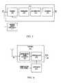
- FIG. 8shows an example of a wireless communication network according to another embodiment of the present invention.
- the networkexemplifies a point-to-multi-point network and includes a plurality of CPE's including a first CPE 603 and a second CPE 605 , and a base station (BTS) 607 .
- the base station 607is connected to a public switched network, and the network further includes a co-ordination server 609 for coordinating the operation of the CPE's within the cell or sector served by the base station 607 , and optionally may co-ordinate the operation of CPE's served by one or more other base stations.
- the first CPE 603is a small office home office (SOHO) and the second CPE is a small or medium enterprise (SME)
- the CPEsmay be of any other type, without limitation.
- the BTSmay be connected to the public switched network by optical fiber and the co-ordination server 609 may be located in a network management center.
- Each CPEincludes one or more data processors 611 , 613 , 615 , 617 , 619 and a router 621 , 623 for transmitting data from the data processor(s) over its respective wireless communication link to the base station 607 .
- Each routermay include a transmitter similar to that described above, for example a transmitter shown in any one of FIGS. 1 to 3 and 6 .
- the data processorsmay communicate with the router through any suitable communication system, for example through an Ethernet link or network.
- the communication channel between the first CPE 603 and the base station 607is experiencing adverse transmission conditions caused for example by adverse weather such as rain, sleet, hail or snow.
- the CPE transmitterincreases the power of the RF signal to compensate for attenuation of the up-link signal caused by the adverse weather conditions.
- the second CPE 605is experiencing heavy traffic flow such that a congestion condition is determined.
- the transmitter of the second CPE 605increases the capacity or data flow rate of its up-link channel to the base station 607 and also increases its power to facilitate transmission at the higher data flow rate.
- the increase in capacity and power of the transmittermay be controlled in accordance with any of the control methods described above, as well as other control methods.
- FIG. 9shows an example of a flow diagram, for example describing an algorithm, which may be used in controlling the operation of a transmitter.
- the algorithmmay, for example, be implemented in the processing engine of the embodiment of FIG. 6 .
- the processorreceives certain data associated with the wireless communication channel on the basis of which the transmitter is controlled.
- the second step 705determines whether adverse conditions, caused for example by rain are affecting the transmission channel and if this is the case, the algorithm passes to step 707 which causes the power of the transmission signal to be increased and the capacity of the transmission channel or the data rate to be decreased.
- the capacity of the communication channelcan be reduced by reducing the modulation rate (i.e.
- the presence of rain or other adverse conditionsmay be detected by any suitable means, for example by an increased bit error rate in the up-link or down-link or by a reduction in power at the receiver of the up-link or down-link.
- step 709determines whether the flow of incoming data to the transmitter is causing a congestion condition. If congestion is detected, the algorithm passes to 711 which determines whether the up-link channel is upsetting another communication channel, for example by interference. If the up-link channel is not upsetting another communication channel, the algorithm passes to step 713 which specifies both a high level of output power and a high data carrying capacity for the transmission channel. However, if at step 711 it is determined that the transmission channel is upsetting another communication channel, the algorithm passes to step 715 which specifies a normal power level and normal data carrying capacity for the transmission channel.
- step 709determines whether the incoming data flow is such that the transmitter is underloaded. If the answer is “No”, the algorithm passes to step 715 which specifies both normal output power and normal data carrying capacity for the wireless transmission channel. On the other hand, if at step 717 , an underloaded condition is determined, the algorithm passes to step 719 which specifies both low output power and low data carrying capacity for the wireless communication channel. Appropriate control signals for controlling the operation of the transmitter are output at step 721 .
- a wireless communication network 801includes a first base station (BTS) 803 and a first CPE 805 which includes a wireless transceiver 807 for sending and receiving data to and from the base station over a bi-directional wireless communication link.
- the communication networkfurther includes a second base station 809 and a second CPE 811 which has a wireless transceiver 813 for communicating with the second base station 809 over a wireless communication channel.
- the respective first and second base stations and CPE'smay be located in neighbouring sectors or cells.
- the first and second base stations 803 , 809are connected to a public switched network, for example by optical fiber, cable or twisted pairs.
- a co-ordination server 815is provided to co-ordinate the operation of the transmitters 807 , 813 of both CPEs 805 , 811 .
- the transceivers 807 , 811 of each CPEmay be similar to that described above and shown in FIG. 6 .
- the control or processing engine 407will increase the power of the wireless transmission signal and may at the same time increase the data carrying capacity of the channel, for example by increasing the modulation level of the modulator 413 .
- the transmittermay also generate and transmit a message indicative of the congestion condition to the base station 803 and the base station passes the message to the server 815 .
- the increased power levelmay or may not be sufficient to cause interference with the communication channel between the second CPE 811 and the second base station 809 .
- the new power levelmay be insufficient to cause interference if the second CPE 811 either has no data to send or is in a low data carrying capacity mode (e.g. operating at a low modulation level, for example QPSK mode) In this case, the communication channel may not be affected by on-channel or co-channel interference (CI). If no interference is detected, the first CPE 805 may increase its power and possibly data carrying capacity further. Before increasing the power level further, the first CPE 805 pauses for a short period of time to allow the second CPE 811 to conduct an interference measurement and issue a complaint or interference notification, if necessary.
- CIco-channel interference
- the second CPEtransmits an interference notification to its base station 809 which passes the notification to the co-ordination server 815 .
- the co-ordination serveridentifies the first CPE 805 as the cause of the interference through information concerning congestion and/or power level received from the first CPE and issues a command or request for the transmitter 807 to reduce its power level. This request or command may be transmitted via the first base station 803 over the wireless down-link channel.
- the processing engine 407 of the first transceiver 807reduces the output power level of the wireless transmission channel by a predetermined amount. If despite the reduction in power level, interference is still detected at the second CPE 811 , an interference notification may again be sent to the co-ordination server 815 and the power level reduced again, and this process may be repeated until interference no longer occurs.
- the transmitter of the first CPE 805continues to transmit data at a higher rate over the higher power, higher capacity channel.
- the processing engineis adapted to reduce the power level and possibly also the data carrying capacity of the channel, as necessary, so that another CPE has the opportunity to use its capability of increasing power and data rate to alleviate its own potential congestion.
- Embodiments of the present inventionmay be implemented in any communication architecture, including point to multi-point, as described above, point-to-point and mesh networks. Furthermore, embodiments of the present invention may be implemented using any suitable access scheme, including time division multiplexing access (TDMA) and frequency division multiplexing access (FDMA).
- TDMAtime division multiplexing access
- FDMAfrequency division multiplexing access
- embodiments of the transmitterhave been described as being implemented in customer premises equipment, other embodiments of the transmitter may be implemented in other equipment, for example in base stations, and embodiments of methods for coordinating operation of the transmitter may be used to co-ordinate operation between base stations.
- the principles of the present inventionmay be applied to satellite systems for example to co-ordinate communication from different satellites, or to co-ordinate communication between a satellite system and a terrestrial wireless system. An example of this latter implementation will now be described with reference to FIG. 11 .
- a communication system 901comprises a terrestrial communication system 903 including first and second transmitters/receivers 905 , 907 .
- the first transmitter/receiveris located at a base station 909 and the second transmitter/receiver is located at a customer premises 911 .
- the communication systemfurther comprises a satellite system 913 which includes an earth based base station 915 which includes a transmitter and receiver 917 and a satellite 919 , which for example may be a low earth orbit (LEO) satellite, which also includes a transmitter and receiver 921 .
- a satellite system 913which includes an earth based base station 915 which includes a transmitter and receiver 917 and a satellite 919 , which for example may be a low earth orbit (LEO) satellite, which also includes a transmitter and receiver 921 .
- LEOlow earth orbit
- Both the terrestrial based communication system and the satellite system 903 , 913may operate at micro-wave frequencies, and depending on the transmission power of the two systems, there may be potential for interference.
- the satellite 919 and/or the satellite base station 915may be controlled to cease communication in order to avoid interference with the terrestrial communication system 903 , if the terrestrial communication system has priority over the satellite communication system.
- the terrestrial based systemmay be controlled to cease communication in order to prevent interference with the satellite communication system.
- an indication of the presence of the satellite over the terrestrial based communication systemmay be transmitted from the satellite base station 915 to the base station 909 , for example through a communication link 923 .
- the base station transmitter and/or the CPE transmittermay cease communication.
- the transmission power of the two systemsmay be co-ordinated, for example depending on the traffic flow through each communication link so that neither the terrestrial based communication system or the satellite communication system need cease communication when the satellite 919 is overhead. For example, if either one or both of the transmitters of the terrestrial based communication system 903 are transmitting at a low data rate, the satellite system 913 may continue to communicate with its base station without causing interference.
- Appropriate messaging between the terrestrial system and the satellitemay be used to control the power of the satellite system 913 to avoid interference, or to prevent interference while obtaining a maximum data rate. Conversely, if the terrestrial based system is transmitting at a high data rate as the satellite passes overhead, the satellite system may be controlled by appropriate messaging between the terrestrial based system and the satellite system to reduce its power to prevent interference with the terrestrial communication system.
- the capacity or data rate of the satellite channelmay be reduced to facilitate reception of the lower power satellite channel.
- the terrestrial communication system 903may continue communication without causing interference of the satellite channel.
- the terrestrial based communication system 903may be controlled to reduce its power to prevent interference with the satellite system.
- the capacity or data rate of one or both of the terrestrial based communication channelsmay be reduced to facilitate reception of the reduced power channel(s).
- any one or more of the transmitters of the terrestrial communication system and the satellite communication systemmay be similar and have similar functions to the embodiments described above, for example as shown in FIGS. 1 , 2 , 3 and 6 .
- the transmittermay be capable of controlling the power of the output signal and also the capacity or data rate of the channel, for example by controlling the modulation or encoding level, for example to compensate for signal attenuation caused by adverse conditions and to handle a congestion condition.
- Co-ordination between the terrestrial communication system and the satellitemay be implemented by a server 925 which may include an information data base which receives and stores information concerning operating conditions of the terrestrial and satellite communication systems, makes decisions based on the received information and issues control signals for controlling the systems.
- the transmitter, receiver, control system and method of communication controlmay be implemented in any wireless communication system, including fixed transmitter and receiver systems, and broad band wireless systems for example operating at micro-wave frequencies at or above about 2 GHz.
Landscapes
- Engineering & Computer Science (AREA)
- Signal Processing (AREA)
- Computer Networks & Wireless Communication (AREA)
- Quality & Reliability (AREA)
- Mobile Radio Communication Systems (AREA)
- Transmitters (AREA)
Abstract
Description
Claims (24)
Priority Applications (1)
| Application Number | Priority Date | Filing Date | Title |
|---|---|---|---|
| US09/990,349US7454222B2 (en) | 2000-11-22 | 2001-11-23 | Apparatus and method for controlling wireless communication signals |
Applications Claiming Priority (2)
| Application Number | Priority Date | Filing Date | Title |
|---|---|---|---|
| US25246300P | 2000-11-22 | 2000-11-22 | |
| US09/990,349US7454222B2 (en) | 2000-11-22 | 2001-11-23 | Apparatus and method for controlling wireless communication signals |
Publications (2)
| Publication Number | Publication Date |
|---|---|
| US20020061073A1 US20020061073A1 (en) | 2002-05-23 |
| US7454222B2true US7454222B2 (en) | 2008-11-18 |
Family
ID=26942339
Family Applications (1)
| Application Number | Title | Priority Date | Filing Date |
|---|---|---|---|
| US09/990,349Expired - LifetimeUS7454222B2 (en) | 2000-11-22 | 2001-11-23 | Apparatus and method for controlling wireless communication signals |
Country Status (1)
| Country | Link |
|---|---|
| US (1) | US7454222B2 (en) |
Cited By (64)
| Publication number | Priority date | Publication date | Assignee | Title |
|---|---|---|---|---|
| US20070258377A1 (en)* | 2006-05-08 | 2007-11-08 | Nokia Corporation | Multi Mode Host Interface for and Remote Register and Memory Access of a Wireless Communication Module |
| US20080032733A1 (en)* | 2006-08-04 | 2008-02-07 | Terrace Communications, Corp. | Techniques to control power by controlling agreggate traffic in a channel |
| US20080274702A1 (en)* | 2003-10-27 | 2008-11-06 | Matthias Keller | Method and Device for Measuring Radio Interference Levels With Frequency Tracking |
| US20090010241A1 (en)* | 2007-06-07 | 2009-01-08 | Shigenori Uchida | Transmission Device, Transmission Method, and Computer-Readable Medium |
| US20090061954A1 (en)* | 2007-08-29 | 2009-03-05 | Ati Technologies Ulc | Server initiated power mode switching in portable communication devices |
| US20090129453A1 (en)* | 2007-11-14 | 2009-05-21 | Andreas Vedral | Method for identifying noise sources for automation devices, and noise source identification unit therefore |
| US20090137264A1 (en)* | 2006-01-03 | 2009-05-28 | Tatsuki Matsumoto | Wireless communication system, communication terminal device, method of controlling transmission power thereof, and program |
| US20090197631A1 (en)* | 2008-02-01 | 2009-08-06 | Qualcomm Incorporated | Interference mitigation for control channels in a wireless communication network |
| US20090279478A1 (en)* | 2008-05-06 | 2009-11-12 | Motorola, Inc. | Method and apparatus for facilitating dynamic cooperative interference reduction |
| US20100120367A1 (en)* | 2008-11-07 | 2010-05-13 | Qualcomm Incorporated | Systems and methods of reducing interference |
| US20100130133A1 (en)* | 2008-11-25 | 2010-05-27 | Yuang Lou | Adaptive sinr control |
| US20100240387A1 (en)* | 2007-12-20 | 2010-09-23 | Fujitsu Limited | Method for controlling an uplink power in a wireless communication system and an apparatus in the system |
| US20110143805A1 (en)* | 2009-12-14 | 2011-06-16 | Apple Inc. | Method and apparatus to improve the robustness of a wireless communication link |
| US20110299644A1 (en)* | 2010-06-08 | 2011-12-08 | Bing Xu | Emission Suppression for Wireless Communication Devices |
| US20120066531A1 (en)* | 2010-09-14 | 2012-03-15 | Sarance Technologies, Inc. | Method and apparatus for adaptive power control in a multi-lane communication channel |
| US8532492B2 (en) | 2009-02-03 | 2013-09-10 | Corning Cable Systems Llc | Optical fiber-based distributed antenna systems, components, and related methods for calibration thereof |
| US8599705B2 (en) | 2008-02-01 | 2013-12-03 | Qualcomm Incorporated | Interference management based on enhanced pilot measurement reports |
| US8639121B2 (en) | 2009-11-13 | 2014-01-28 | Corning Cable Systems Llc | Radio-over-fiber (RoF) system for protocol-independent wired and/or wireless communication |
| US8644844B2 (en) | 2007-12-20 | 2014-02-04 | Corning Mobileaccess Ltd. | Extending outdoor location based services and applications into enclosed areas |
| US20140162564A1 (en)* | 2012-12-11 | 2014-06-12 | Fujitsu Limited | Communication control apparatus, communication control method, mobile station, communication method, and communication system |
| US8831428B2 (en) | 2010-02-15 | 2014-09-09 | Corning Optical Communications LLC | Dynamic cell bonding (DCB) for radio-over-fiber (RoF)-based networks and communication systems and related methods |
| US8873585B2 (en) | 2006-12-19 | 2014-10-28 | Corning Optical Communications Wireless Ltd | Distributed antenna system for MIMO technologies |
| US8983301B2 (en) | 2010-03-31 | 2015-03-17 | Corning Optical Communications LLC | Localization services in optical fiber-based distributed communications components and systems, and related methods |
| US9158864B2 (en) | 2012-12-21 | 2015-10-13 | Corning Optical Communications Wireless Ltd | Systems, methods, and devices for documenting a location of installed equipment |
| US9178635B2 (en) | 2014-01-03 | 2015-11-03 | Corning Optical Communications Wireless Ltd | Separation of communication signal sub-bands in distributed antenna systems (DASs) to reduce interference |
| US9184843B2 (en) | 2011-04-29 | 2015-11-10 | Corning Optical Communications LLC | Determining propagation delay of communications in distributed antenna systems, and related components, systems, and methods |
| US9185674B2 (en) | 2010-08-09 | 2015-11-10 | Corning Cable Systems Llc | Apparatuses, systems, and methods for determining location of a mobile device(s) in a distributed antenna system(s) |
| US9219546B2 (en) | 2011-12-12 | 2015-12-22 | Corning Optical Communications LLC | Extremely high frequency (EHF) distributed antenna systems, and related components and methods |
| US9240835B2 (en) | 2011-04-29 | 2016-01-19 | Corning Optical Communications LLC | Systems, methods, and devices for increasing radio frequency (RF) power in distributed antenna systems |
| US9247543B2 (en) | 2013-07-23 | 2016-01-26 | Corning Optical Communications Wireless Ltd | Monitoring non-supported wireless spectrum within coverage areas of distributed antenna systems (DASs) |
| US9258052B2 (en) | 2012-03-30 | 2016-02-09 | Corning Optical Communications LLC | Reducing location-dependent interference in distributed antenna systems operating in multiple-input, multiple-output (MIMO) configuration, and related components, systems, and methods |
| US9323020B2 (en) | 2008-10-09 | 2016-04-26 | Corning Cable Systems (Shanghai) Co. Ltd | Fiber optic terminal having adapter panel supporting both input and output fibers from an optical splitter |
| US9357551B2 (en) | 2014-05-30 | 2016-05-31 | Corning Optical Communications Wireless Ltd | Systems and methods for simultaneous sampling of serial digital data streams from multiple analog-to-digital converters (ADCS), including in distributed antenna systems |
| US9385810B2 (en) | 2013-09-30 | 2016-07-05 | Corning Optical Communications Wireless Ltd | Connection mapping in distributed communication systems |
| US9420542B2 (en) | 2014-09-25 | 2016-08-16 | Corning Optical Communications Wireless Ltd | System-wide uplink band gain control in a distributed antenna system (DAS), based on per band gain control of remote uplink paths in remote units |
| US9455784B2 (en) | 2012-10-31 | 2016-09-27 | Corning Optical Communications Wireless Ltd | Deployable wireless infrastructures and methods of deploying wireless infrastructures |
| US9525472B2 (en) | 2014-07-30 | 2016-12-20 | Corning Incorporated | Reducing location-dependent destructive interference in distributed antenna systems (DASS) operating in multiple-input, multiple-output (MIMO) configuration, and related components, systems, and methods |
| US9531452B2 (en) | 2012-11-29 | 2016-12-27 | Corning Optical Communications LLC | Hybrid intra-cell / inter-cell remote unit antenna bonding in multiple-input, multiple-output (MIMO) distributed antenna systems (DASs) |
| US9547145B2 (en) | 2010-10-19 | 2017-01-17 | Corning Optical Communications LLC | Local convergence point for multiple dwelling unit fiber optic distribution network |
| US9590763B2 (en)* | 2015-05-11 | 2017-03-07 | Telefonaktiebolaget Lm Ericsson (Publ) | Energy efficient transmitter power control |
| US9590733B2 (en) | 2009-07-24 | 2017-03-07 | Corning Optical Communications LLC | Location tracking using fiber optic array cables and related systems and methods |
| US9602210B2 (en) | 2014-09-24 | 2017-03-21 | Corning Optical Communications Wireless Ltd | Flexible head-end chassis supporting automatic identification and interconnection of radio interface modules and optical interface modules in an optical fiber-based distributed antenna system (DAS) |
| US9621293B2 (en) | 2012-08-07 | 2017-04-11 | Corning Optical Communications Wireless Ltd | Distribution of time-division multiplexed (TDM) management services in a distributed antenna system, and related components, systems, and methods |
| US9648580B1 (en) | 2016-03-23 | 2017-05-09 | Corning Optical Communications Wireless Ltd | Identifying remote units in a wireless distribution system (WDS) based on assigned unique temporal delay patterns |
| US9647758B2 (en) | 2012-11-30 | 2017-05-09 | Corning Optical Communications Wireless Ltd | Cabling connectivity monitoring and verification |
| US9661781B2 (en) | 2013-07-31 | 2017-05-23 | Corning Optical Communications Wireless Ltd | Remote units for distributed communication systems and related installation methods and apparatuses |
| US9673904B2 (en) | 2009-02-03 | 2017-06-06 | Corning Optical Communications LLC | Optical fiber-based distributed antenna systems, components, and related methods for calibration thereof |
| US9681313B2 (en) | 2015-04-15 | 2017-06-13 | Corning Optical Communications Wireless Ltd | Optimizing remote antenna unit performance using an alternative data channel |
| US9715157B2 (en) | 2013-06-12 | 2017-07-25 | Corning Optical Communications Wireless Ltd | Voltage controlled optical directional coupler |
| US9730228B2 (en) | 2014-08-29 | 2017-08-08 | Corning Optical Communications Wireless Ltd | Individualized gain control of remote uplink band paths in a remote unit in a distributed antenna system (DAS), based on combined uplink power level in the remote unit |
| US9729267B2 (en) | 2014-12-11 | 2017-08-08 | Corning Optical Communications Wireless Ltd | Multiplexing two separate optical links with the same wavelength using asymmetric combining and splitting |
| WO2017143315A1 (en)* | 2016-02-18 | 2017-08-24 | The Johns Hopkins University | Pulse ratio modulation |
| US9775123B2 (en) | 2014-03-28 | 2017-09-26 | Corning Optical Communications Wireless Ltd. | Individualized gain control of uplink paths in remote units in a distributed antenna system (DAS) based on individual remote unit contribution to combined uplink power |
| US9781553B2 (en) | 2012-04-24 | 2017-10-03 | Corning Optical Communications LLC | Location based services in a distributed communication system, and related components and methods |
| US9807700B2 (en) | 2015-02-19 | 2017-10-31 | Corning Optical Communications Wireless Ltd | Offsetting unwanted downlink interference signals in an uplink path in a distributed antenna system (DAS) |
| US9948349B2 (en) | 2015-07-17 | 2018-04-17 | Corning Optical Communications Wireless Ltd | IOT automation and data collection system |
| US9974074B2 (en) | 2013-06-12 | 2018-05-15 | Corning Optical Communications Wireless Ltd | Time-division duplexing (TDD) in distributed communications systems, including distributed antenna systems (DASs) |
| US10110307B2 (en) | 2012-03-02 | 2018-10-23 | Corning Optical Communications LLC | Optical network units (ONUs) for high bandwidth connectivity, and related components and methods |
| US10128951B2 (en) | 2009-02-03 | 2018-11-13 | Corning Optical Communications LLC | Optical fiber-based distributed antenna systems, components, and related methods for monitoring and configuring thereof |
| US10136200B2 (en) | 2012-04-25 | 2018-11-20 | Corning Optical Communications LLC | Distributed antenna system architectures |
| US10236924B2 (en) | 2016-03-31 | 2019-03-19 | Corning Optical Communications Wireless Ltd | Reducing out-of-channel noise in a wireless distribution system (WDS) |
| US10448342B1 (en)* | 2018-10-19 | 2019-10-15 | Motorola Mobility Llc | Aggregate transmit power limiting on uncoordinated multiple transmitter device |
| US10560214B2 (en) | 2015-09-28 | 2020-02-11 | Corning Optical Communications LLC | Downlink and uplink communication path switching in a time-division duplex (TDD) distributed antenna system (DAS) |
| US11671914B2 (en) | 2010-10-13 | 2023-06-06 | Corning Optical Communications LLC | Power management for remote antenna units in distributed antenna systems |
Families Citing this family (54)
| Publication number | Priority date | Publication date | Assignee | Title |
|---|---|---|---|---|
| US6690884B1 (en)* | 1999-02-19 | 2004-02-10 | Corvis Corporation | Optical transmission systems including error correction and protection apparatuses and methods |
| US9485010B1 (en) | 2001-09-10 | 2016-11-01 | The Directv Group, Inc. | Adaptive coding and modulation for spot beam satellite broadcast |
| US7646816B2 (en)* | 2001-09-19 | 2010-01-12 | Microsoft Corporation | Generalized reference decoder for image or video processing |
| FI113232B (en)* | 2002-06-28 | 2004-03-15 | Nokia Corp | Arranging a data connection |
| US8306562B2 (en)* | 2003-05-29 | 2012-11-06 | Texas Instruments Incorporated | Signal-to-interference ratio target control for multi-data-rate communication systems |
| US7380028B2 (en)* | 2003-06-13 | 2008-05-27 | Microsoft Corporation | Robust delivery of video data |
| US7653349B1 (en)* | 2003-06-18 | 2010-01-26 | The Directv Group, Inc. | Adaptive return link for two-way satellite communication systems |
| US7817591B2 (en)* | 2003-08-22 | 2010-10-19 | Agere Systems Inc. | Dedicated local internet radio |
| JP4194091B2 (en)* | 2003-09-02 | 2008-12-10 | ソニー・エリクソン・モバイルコミュニケーションズ株式会社 | Wireless communication system and wireless communication apparatus |
| US8107531B2 (en)* | 2003-09-07 | 2012-01-31 | Microsoft Corporation | Signaling and repeat padding for skip frames |
| US7724827B2 (en)* | 2003-09-07 | 2010-05-25 | Microsoft Corporation | Multi-layer run level encoding and decoding |
| US8582659B2 (en) | 2003-09-07 | 2013-11-12 | Microsoft Corporation | Determining a decoding time stamp from buffer fullness |
| US8345754B2 (en)* | 2003-09-07 | 2013-01-01 | Microsoft Corporation | Signaling buffer fullness |
| US7961786B2 (en)* | 2003-09-07 | 2011-06-14 | Microsoft Corporation | Signaling field type information |
| GB0323246D0 (en)* | 2003-10-03 | 2003-11-05 | Fujitsu Ltd | Virtually centralized uplink scheduling |
| US7616888B2 (en)* | 2003-11-06 | 2009-11-10 | Itt Manufacturing Enterprises, Inc. | Method and system for measuring optical properties of a medium using digital communication processing techniques |
| EP1585217B1 (en)* | 2004-04-08 | 2007-09-19 | STMicroelectronics N.V. | Process of controlling the power of the output signal of an amplifier system, and associated system |
| US7664520B2 (en)* | 2004-06-24 | 2010-02-16 | Nokia Corporation | Low current direct conversion transmitter architecture |
| JP2006050306A (en)* | 2004-08-05 | 2006-02-16 | Matsushita Electric Ind Co Ltd | Communication apparatus and communication system using the same |
| US20060084444A1 (en)* | 2004-10-20 | 2006-04-20 | Nokia Corporation | System and method utilizing a cognitive transceiver for ad hoc networking |
| US20060104356A1 (en)* | 2004-11-15 | 2006-05-18 | Microsoft Corporation | Timing for decoder buffer examination |
| US8059539B2 (en)* | 2004-12-29 | 2011-11-15 | Hewlett-Packard Development Company, L.P. | Link throughput enhancer |
| US20060146875A1 (en)* | 2005-01-04 | 2006-07-06 | Yang Luiyang L | Media access controller and methods for distributed hop-by-hop flow control in wireless mesh networks |
| US9204428B2 (en)* | 2005-10-26 | 2015-12-01 | Qualcomm Incorporated | Interference management using resource utilization masks sent at constant PSD |
| US8942161B2 (en)* | 2005-10-26 | 2015-01-27 | Qualcomm Incorporated | Weighted fair sharing of a wireless channel using resource utilization masks |
| US20070115817A1 (en)* | 2005-10-26 | 2007-05-24 | Qualcomm Incorporated | Minimum rate guarantees on wireless channel using resource utilization messages |
| US8081592B2 (en)* | 2005-10-26 | 2011-12-20 | Qualcomm Incorporated | Flexible medium access control (MAC) for ad hoc deployed wireless networks |
| US8918114B2 (en)* | 2005-10-26 | 2014-12-23 | Qualcomm Incorporated | Using resource utilization messages in a multi-carrier MAC to achieve fairness |
| US20070220403A1 (en)* | 2006-02-27 | 2007-09-20 | Honeywell International Inc. | System and method for dynamic allocation of forward error encoding |
| EP1838004A1 (en)* | 2006-03-21 | 2007-09-26 | Nokia Siemens Networks Gmbh & Co. Kg | Method, system and radio station for interference cancellation |
| US20080064400A1 (en)* | 2006-09-13 | 2008-03-13 | Benco David S | Method for detection and recovery from wireless signal interference |
| WO2008118051A1 (en)* | 2007-03-26 | 2008-10-02 | Telefonaktiebolaget Lm Ericsson (Publ) | Method for controlling output power in a radio communications network |
| US20090161797A1 (en)* | 2007-06-08 | 2009-06-25 | Cowles Philip R | Satellite detection of automatic identification system signals |
| US7876865B2 (en)* | 2007-06-08 | 2011-01-25 | COM DEV International Ltd | System and method for decoding automatic identification system signals |
| US8396413B2 (en)* | 2007-10-25 | 2013-03-12 | Agere Systems Llc | Providing a virtual local channel in a satellite broadcast system |
| JP5115179B2 (en)* | 2007-12-20 | 2013-01-09 | 日本電気株式会社 | Wireless communication control device, wireless communication control system, wireless communication control method, wireless communication control program, and recording medium |
| US20090175324A1 (en)* | 2008-01-04 | 2009-07-09 | Qualcomm Incorporated | Dynamic interference control in a wireless communication network |
| US8995559B2 (en) | 2008-03-28 | 2015-03-31 | Qualcomm Incorporated | Signaling message transmission in a wireless communication network |
| US9276787B2 (en)* | 2008-03-28 | 2016-03-01 | Qualcomm Incorporated | Transmission of signaling messages using beacon signals |
| US9226300B2 (en)* | 2008-07-11 | 2015-12-29 | Qualcomm Incorporated | Hierarchical control channel structure for wireless communication |
| US8780788B2 (en) | 2009-09-25 | 2014-07-15 | Com Dev International Ltd. | Systems and methods for decoding automatic identification system signals |
| US10111111B2 (en) | 2009-11-19 | 2018-10-23 | Qualcomm Incorporated | Per-cell timing and/or frequency acquisition and their use on channel estimation in wireless networks |
| US9331774B2 (en) | 2010-06-09 | 2016-05-03 | Exactearth Ltd. | Systems and methods for segmenting a satellite field of view for detecting radio frequency signals |
| US8737925B2 (en)* | 2011-03-10 | 2014-05-27 | Comtech Ef Data Corp. | Method for the control of a wireless communications link for mitigating adjacent satellite interference |
| US9480028B1 (en)* | 2011-06-10 | 2016-10-25 | Arris Enterprises, Inc. | Adjusting transmission power in customer premise equipment |
| US9537794B2 (en)* | 2011-07-29 | 2017-01-03 | Vubiq Networks, Inc. | System and method for wireless communication in a backplane fabric architecture |
| US8849965B2 (en) | 2011-10-19 | 2014-09-30 | Honeywell International Inc. | Wireless network performance monitoring |
| KR20130099689A (en)* | 2012-02-29 | 2013-09-06 | 주식회사 팬택 | Method for reducing intermodulation noise signal between antenas and apparatus using thereof |
| US9015567B2 (en) | 2012-04-12 | 2015-04-21 | Com Dev International Ltd. | Methods and systems for consistency checking and anomaly detection in automatic identification system signal data |
| WO2015136325A1 (en)* | 2014-03-11 | 2015-09-17 | Telefonaktiebolaget L M Ericsson (Publ) | Physical downlink control channel (pdcch) inter-cell-interference coordination |
| AU2017274420B2 (en)* | 2016-06-01 | 2022-06-09 | Anatrope, Inc. | Methods and apparatus for intercepting and analyzing signals emitted from vehicles |
| US10211970B2 (en)* | 2017-03-31 | 2019-02-19 | Intel Corporation | Millimeter wave CMOS engines for waveguide fabrics |
| US20220317898A1 (en)* | 2021-04-03 | 2022-10-06 | EMC IP Holding Company LLC | Managing Application Storage Resource Allocations Based on Application Specific Storage Policies |
| CN118870318A (en)* | 2023-11-28 | 2024-10-29 | 浙江龙感科技有限公司成都分公司 | A passive wireless sensor control system and control method |
Citations (2)
| Publication number | Priority date | Publication date | Assignee | Title |
|---|---|---|---|---|
| US5504938A (en)* | 1994-05-02 | 1996-04-02 | Motorola, Inc. | Method and apparatus for varying apparent cell size in a cellular communication system |
| US5914950A (en)* | 1997-04-08 | 1999-06-22 | Qualcomm Incorporated | Method and apparatus for reverse link rate scheduling |
- 2001
- 2001-11-23USUS09/990,349patent/US7454222B2/ennot_activeExpired - Lifetime
Patent Citations (2)
| Publication number | Priority date | Publication date | Assignee | Title |
|---|---|---|---|---|
| US5504938A (en)* | 1994-05-02 | 1996-04-02 | Motorola, Inc. | Method and apparatus for varying apparent cell size in a cellular communication system |
| US5914950A (en)* | 1997-04-08 | 1999-06-22 | Qualcomm Incorporated | Method and apparatus for reverse link rate scheduling |
Cited By (128)
| Publication number | Priority date | Publication date | Assignee | Title |
|---|---|---|---|---|
| US7801489B2 (en)* | 2003-10-27 | 2010-09-21 | Rohde & Schwarz Gmbh & Co. Kg | Method and device for measuring radio interference levels with frequency tracking |
| US20080274702A1 (en)* | 2003-10-27 | 2008-11-06 | Matthias Keller | Method and Device for Measuring Radio Interference Levels With Frequency Tracking |
| US20090137264A1 (en)* | 2006-01-03 | 2009-05-28 | Tatsuki Matsumoto | Wireless communication system, communication terminal device, method of controlling transmission power thereof, and program |
| US8417278B2 (en)* | 2006-03-01 | 2013-04-09 | Nec Corporation | Wireless communication system, communication terminal device, method of controlling transmission power thereof, and program |
| US8300565B2 (en)* | 2006-05-08 | 2012-10-30 | Nokia Corporation | Multi mode host interface for and remote register and memory access of a wireless communication module |
| US20070258377A1 (en)* | 2006-05-08 | 2007-11-08 | Nokia Corporation | Multi Mode Host Interface for and Remote Register and Memory Access of a Wireless Communication Module |
| US20080032733A1 (en)* | 2006-08-04 | 2008-02-07 | Terrace Communications, Corp. | Techniques to control power by controlling agreggate traffic in a channel |
| US7912492B2 (en)* | 2006-08-04 | 2011-03-22 | Terrace Communications Corporation | Techniques to control power by controlling aggregate traffic in a channel |
| US9130613B2 (en) | 2006-12-19 | 2015-09-08 | Corning Optical Communications Wireless Ltd | Distributed antenna system for MIMO technologies |
| US8873585B2 (en) | 2006-12-19 | 2014-10-28 | Corning Optical Communications Wireless Ltd | Distributed antenna system for MIMO technologies |
| US8861490B2 (en)* | 2007-06-07 | 2014-10-14 | Sony Corporation | Transmission device, transmission method, and computer-readable medium |
| US20090010241A1 (en)* | 2007-06-07 | 2009-01-08 | Shigenori Uchida | Transmission Device, Transmission Method, and Computer-Readable Medium |
| US8165644B2 (en)* | 2007-08-29 | 2012-04-24 | Qualcomm Incorporated | Server initiated power mode switching in portable communication devices |
| US9338744B2 (en) | 2007-08-29 | 2016-05-10 | Qualcomm Incorporated | Server initiated power mode switching in portable communication devices |
| US20090061954A1 (en)* | 2007-08-29 | 2009-03-05 | Ati Technologies Ulc | Server initiated power mode switching in portable communication devices |
| US20090129453A1 (en)* | 2007-11-14 | 2009-05-21 | Andreas Vedral | Method for identifying noise sources for automation devices, and noise source identification unit therefore |
| US8331870B2 (en)* | 2007-11-14 | 2012-12-11 | Wago Verwaltungsgesellschaft Mbh | Method for identifying noise sources for automation devices, and noise source identification unit therefore |
| US8428639B2 (en)* | 2007-12-20 | 2013-04-23 | Fujitsu Limited | Method for controlling an uplink power in a wireless communication system and an apparatus in the system |
| US20100240387A1 (en)* | 2007-12-20 | 2010-09-23 | Fujitsu Limited | Method for controlling an uplink power in a wireless communication system and an apparatus in the system |
| US8644844B2 (en) | 2007-12-20 | 2014-02-04 | Corning Mobileaccess Ltd. | Extending outdoor location based services and applications into enclosed areas |
| US8599705B2 (en) | 2008-02-01 | 2013-12-03 | Qualcomm Incorporated | Interference management based on enhanced pilot measurement reports |
| US9648596B2 (en) | 2008-02-01 | 2017-05-09 | Qualcomm Incorporated | Interference mitigation for control channels in a wireless communication network |
| US20090197631A1 (en)* | 2008-02-01 | 2009-08-06 | Qualcomm Incorporated | Interference mitigation for control channels in a wireless communication network |
| US8504091B2 (en)* | 2008-02-01 | 2013-08-06 | Qualcomm Incorporated | Interference mitigation for control channels in a wireless communication network |
| US20090279478A1 (en)* | 2008-05-06 | 2009-11-12 | Motorola, Inc. | Method and apparatus for facilitating dynamic cooperative interference reduction |
| US9323020B2 (en) | 2008-10-09 | 2016-04-26 | Corning Cable Systems (Shanghai) Co. Ltd | Fiber optic terminal having adapter panel supporting both input and output fibers from an optical splitter |
| US20100120367A1 (en)* | 2008-11-07 | 2010-05-13 | Qualcomm Incorporated | Systems and methods of reducing interference |
| US8676125B2 (en)* | 2008-11-07 | 2014-03-18 | Qualcomm Incorporated | Systems and methods of reducing interference |
| US20150018033A1 (en)* | 2008-11-25 | 2015-01-15 | At&T Intellectual Property I, L.P. | Adaptive sinr control |
| US20100130133A1 (en)* | 2008-11-25 | 2010-05-27 | Yuang Lou | Adaptive sinr control |
| US9713097B2 (en)* | 2008-11-25 | 2017-07-18 | At&T Intellectual Property I, L.P. | Adaptive SINR control |
| US9913224B2 (en)* | 2008-11-25 | 2018-03-06 | At&T Intellectual Property Ii, L.P. | Adaptive SINR control |
| US20170280398A1 (en)* | 2008-11-25 | 2017-09-28 | At&T Intellectual Property I, L.P. | Adaptive sinr control |
| US8849335B2 (en)* | 2008-11-25 | 2014-09-30 | At&T Intellectual Property I, L.P. | Adaptive SINR control |
| US9112611B2 (en) | 2009-02-03 | 2015-08-18 | Corning Optical Communications LLC | Optical fiber-based distributed antenna systems, components, and related methods for calibration thereof |
| US9900097B2 (en) | 2009-02-03 | 2018-02-20 | Corning Optical Communications LLC | Optical fiber-based distributed antenna systems, components, and related methods for calibration thereof |
| US9673904B2 (en) | 2009-02-03 | 2017-06-06 | Corning Optical Communications LLC | Optical fiber-based distributed antenna systems, components, and related methods for calibration thereof |
| US8532492B2 (en) | 2009-02-03 | 2013-09-10 | Corning Cable Systems Llc | Optical fiber-based distributed antenna systems, components, and related methods for calibration thereof |
| US10153841B2 (en) | 2009-02-03 | 2018-12-11 | Corning Optical Communications LLC | Optical fiber-based distributed antenna systems, components, and related methods for calibration thereof |
| US10128951B2 (en) | 2009-02-03 | 2018-11-13 | Corning Optical Communications LLC | Optical fiber-based distributed antenna systems, components, and related methods for monitoring and configuring thereof |
| US9590733B2 (en) | 2009-07-24 | 2017-03-07 | Corning Optical Communications LLC | Location tracking using fiber optic array cables and related systems and methods |
| US10070258B2 (en) | 2009-07-24 | 2018-09-04 | Corning Optical Communications LLC | Location tracking using fiber optic array cables and related systems and methods |
| US9729238B2 (en) | 2009-11-13 | 2017-08-08 | Corning Optical Communications LLC | Radio-over-fiber (ROF) system for protocol-independent wired and/or wireless communication |
| US8639121B2 (en) | 2009-11-13 | 2014-01-28 | Corning Cable Systems Llc | Radio-over-fiber (RoF) system for protocol-independent wired and/or wireless communication |
| US9485022B2 (en) | 2009-11-13 | 2016-11-01 | Corning Optical Communications LLC | Radio-over-fiber (ROF) system for protocol-independent wired and/or wireless communication |
| US9219879B2 (en) | 2009-11-13 | 2015-12-22 | Corning Optical Communications LLC | Radio-over-fiber (ROF) system for protocol-independent wired and/or wireless communication |
| WO2011081853A1 (en)* | 2009-12-14 | 2011-07-07 | Apple Inc. | Method and apparatus to improve the robustness of a wireless communication link |
| US20110143805A1 (en)* | 2009-12-14 | 2011-06-16 | Apple Inc. | Method and apparatus to improve the robustness of a wireless communication link |
| US8554259B2 (en) | 2009-12-14 | 2013-10-08 | Apple Inc. | Method and apparatus to improve the robustness of a wireless communication link |
| US8831428B2 (en) | 2010-02-15 | 2014-09-09 | Corning Optical Communications LLC | Dynamic cell bonding (DCB) for radio-over-fiber (RoF)-based networks and communication systems and related methods |
| US9319138B2 (en) | 2010-02-15 | 2016-04-19 | Corning Optical Communications LLC | Dynamic cell bonding (DCB) for radio-over-fiber (RoF)-based networks and communication systems and related methods |
| US8983301B2 (en) | 2010-03-31 | 2015-03-17 | Corning Optical Communications LLC | Localization services in optical fiber-based distributed communications components and systems, and related methods |
| US9967032B2 (en) | 2010-03-31 | 2018-05-08 | Corning Optical Communications LLC | Localization services in optical fiber-based distributed communications components and systems, and related methods |
| US20110299644A1 (en)* | 2010-06-08 | 2011-12-08 | Bing Xu | Emission Suppression for Wireless Communication Devices |
| US11653175B2 (en) | 2010-08-09 | 2023-05-16 | Corning Optical Communications LLC | Apparatuses, systems, and methods for determining location of a mobile device(s) in a distributed antenna system(s) |
| US9913094B2 (en) | 2010-08-09 | 2018-03-06 | Corning Optical Communications LLC | Apparatuses, systems, and methods for determining location of a mobile device(s) in a distributed antenna system(s) |
| US9185674B2 (en) | 2010-08-09 | 2015-11-10 | Corning Cable Systems Llc | Apparatuses, systems, and methods for determining location of a mobile device(s) in a distributed antenna system(s) |
| US10959047B2 (en) | 2010-08-09 | 2021-03-23 | Corning Optical Communications LLC | Apparatuses, systems, and methods for determining location of a mobile device(s) in a distributed antenna system(s) |
| US12160789B2 (en) | 2010-08-09 | 2024-12-03 | Corning Optical Communications LLC | Apparatuses, systems, and methods for determining location of a mobile device(s) in a distributed antenna system(s) |
| US10448205B2 (en) | 2010-08-09 | 2019-10-15 | Corning Optical Communications LLC | Apparatuses, systems, and methods for determining location of a mobile device(s) in a distributed antenna system(s) |
| US8762760B2 (en)* | 2010-09-14 | 2014-06-24 | Xilinx, Inc. | Method and apparatus for adaptive power control in a multi-lane communication channel |
| US20120066531A1 (en)* | 2010-09-14 | 2012-03-15 | Sarance Technologies, Inc. | Method and apparatus for adaptive power control in a multi-lane communication channel |
| US11671914B2 (en) | 2010-10-13 | 2023-06-06 | Corning Optical Communications LLC | Power management for remote antenna units in distributed antenna systems |
| US9547145B2 (en) | 2010-10-19 | 2017-01-17 | Corning Optical Communications LLC | Local convergence point for multiple dwelling unit fiber optic distribution network |
| US9720197B2 (en) | 2010-10-19 | 2017-08-01 | Corning Optical Communications LLC | Transition box for multiple dwelling unit fiber optic distribution network |
| US10148347B2 (en) | 2011-04-29 | 2018-12-04 | Corning Optical Communications LLC | Systems, methods, and devices for increasing radio frequency (RF) power in distributed antenna systems |
| US9240835B2 (en) | 2011-04-29 | 2016-01-19 | Corning Optical Communications LLC | Systems, methods, and devices for increasing radio frequency (RF) power in distributed antenna systems |
| US9184843B2 (en) | 2011-04-29 | 2015-11-10 | Corning Optical Communications LLC | Determining propagation delay of communications in distributed antenna systems, and related components, systems, and methods |
| US9369222B2 (en) | 2011-04-29 | 2016-06-14 | Corning Optical Communications LLC | Determining propagation delay of communications in distributed antenna systems, and related components, systems, and methods |
| US9807722B2 (en) | 2011-04-29 | 2017-10-31 | Corning Optical Communications LLC | Determining propagation delay of communications in distributed antenna systems, and related components, systems, and methods |
| US9806797B2 (en) | 2011-04-29 | 2017-10-31 | Corning Optical Communications LLC | Systems, methods, and devices for increasing radio frequency (RF) power in distributed antenna systems |
| US9800339B2 (en) | 2011-12-12 | 2017-10-24 | Corning Optical Communications LLC | Extremely high frequency (EHF) distributed antenna systems, and related components and methods |
| US9602209B2 (en) | 2011-12-12 | 2017-03-21 | Corning Optical Communications LLC | Extremely high frequency (EHF) distributed antenna systems, and related components and methods |
| US10110305B2 (en) | 2011-12-12 | 2018-10-23 | Corning Optical Communications LLC | Extremely high frequency (EHF) distributed antenna systems, and related components and methods |
| US9219546B2 (en) | 2011-12-12 | 2015-12-22 | Corning Optical Communications LLC | Extremely high frequency (EHF) distributed antenna systems, and related components and methods |
| US10110307B2 (en) | 2012-03-02 | 2018-10-23 | Corning Optical Communications LLC | Optical network units (ONUs) for high bandwidth connectivity, and related components and methods |
| US9258052B2 (en) | 2012-03-30 | 2016-02-09 | Corning Optical Communications LLC | Reducing location-dependent interference in distributed antenna systems operating in multiple-input, multiple-output (MIMO) configuration, and related components, systems, and methods |
| US9813127B2 (en) | 2012-03-30 | 2017-11-07 | Corning Optical Communications LLC | Reducing location-dependent interference in distributed antenna systems operating in multiple-input, multiple-output (MIMO) configuration, and related components, systems, and methods |
| US9781553B2 (en) | 2012-04-24 | 2017-10-03 | Corning Optical Communications LLC | Location based services in a distributed communication system, and related components and methods |
| US10349156B2 (en) | 2012-04-25 | 2019-07-09 | Corning Optical Communications LLC | Distributed antenna system architectures |
| US10136200B2 (en) | 2012-04-25 | 2018-11-20 | Corning Optical Communications LLC | Distributed antenna system architectures |
| US9621293B2 (en) | 2012-08-07 | 2017-04-11 | Corning Optical Communications Wireless Ltd | Distribution of time-division multiplexed (TDM) management services in a distributed antenna system, and related components, systems, and methods |
| US9973968B2 (en) | 2012-08-07 | 2018-05-15 | Corning Optical Communications Wireless Ltd | Distribution of time-division multiplexed (TDM) management services in a distributed antenna system, and related components, systems, and methods |
| US9455784B2 (en) | 2012-10-31 | 2016-09-27 | Corning Optical Communications Wireless Ltd | Deployable wireless infrastructures and methods of deploying wireless infrastructures |
| US9531452B2 (en) | 2012-11-29 | 2016-12-27 | Corning Optical Communications LLC | Hybrid intra-cell / inter-cell remote unit antenna bonding in multiple-input, multiple-output (MIMO) distributed antenna systems (DASs) |
| US10361782B2 (en) | 2012-11-30 | 2019-07-23 | Corning Optical Communications LLC | Cabling connectivity monitoring and verification |
| US9647758B2 (en) | 2012-11-30 | 2017-05-09 | Corning Optical Communications Wireless Ltd | Cabling connectivity monitoring and verification |
| US20140162564A1 (en)* | 2012-12-11 | 2014-06-12 | Fujitsu Limited | Communication control apparatus, communication control method, mobile station, communication method, and communication system |
| US9037185B2 (en)* | 2012-12-11 | 2015-05-19 | Fujitsu Limited | Communication control apparatus, communication control method, mobile station, communication method, and communication system |
| US9414192B2 (en) | 2012-12-21 | 2016-08-09 | Corning Optical Communications Wireless Ltd | Systems, methods, and devices for documenting a location of installed equipment |
| US9158864B2 (en) | 2012-12-21 | 2015-10-13 | Corning Optical Communications Wireless Ltd | Systems, methods, and devices for documenting a location of installed equipment |
| US9974074B2 (en) | 2013-06-12 | 2018-05-15 | Corning Optical Communications Wireless Ltd | Time-division duplexing (TDD) in distributed communications systems, including distributed antenna systems (DASs) |
| US9715157B2 (en) | 2013-06-12 | 2017-07-25 | Corning Optical Communications Wireless Ltd | Voltage controlled optical directional coupler |
| US11792776B2 (en) | 2013-06-12 | 2023-10-17 | Corning Optical Communications LLC | Time-division duplexing (TDD) in distributed communications systems, including distributed antenna systems (DASs) |
| US11291001B2 (en) | 2013-06-12 | 2022-03-29 | Corning Optical Communications LLC | Time-division duplexing (TDD) in distributed communications systems, including distributed antenna systems (DASs) |
| US9247543B2 (en) | 2013-07-23 | 2016-01-26 | Corning Optical Communications Wireless Ltd | Monitoring non-supported wireless spectrum within coverage areas of distributed antenna systems (DASs) |
| US9526020B2 (en) | 2013-07-23 | 2016-12-20 | Corning Optical Communications Wireless Ltd | Monitoring non-supported wireless spectrum within coverage areas of distributed antenna systems (DASs) |
| US9967754B2 (en) | 2013-07-23 | 2018-05-08 | Corning Optical Communications Wireless Ltd | Monitoring non-supported wireless spectrum within coverage areas of distributed antenna systems (DASs) |
| US10292056B2 (en) | 2013-07-23 | 2019-05-14 | Corning Optical Communications LLC | Monitoring non-supported wireless spectrum within coverage areas of distributed antenna systems (DASs) |
| US9661781B2 (en) | 2013-07-31 | 2017-05-23 | Corning Optical Communications Wireless Ltd | Remote units for distributed communication systems and related installation methods and apparatuses |
| US9385810B2 (en) | 2013-09-30 | 2016-07-05 | Corning Optical Communications Wireless Ltd | Connection mapping in distributed communication systems |
| US9178635B2 (en) | 2014-01-03 | 2015-11-03 | Corning Optical Communications Wireless Ltd | Separation of communication signal sub-bands in distributed antenna systems (DASs) to reduce interference |
| US9775123B2 (en) | 2014-03-28 | 2017-09-26 | Corning Optical Communications Wireless Ltd. | Individualized gain control of uplink paths in remote units in a distributed antenna system (DAS) based on individual remote unit contribution to combined uplink power |
| US9807772B2 (en) | 2014-05-30 | 2017-10-31 | Corning Optical Communications Wireless Ltd. | Systems and methods for simultaneous sampling of serial digital data streams from multiple analog-to-digital converters (ADCs), including in distributed antenna systems |
| US9357551B2 (en) | 2014-05-30 | 2016-05-31 | Corning Optical Communications Wireless Ltd | Systems and methods for simultaneous sampling of serial digital data streams from multiple analog-to-digital converters (ADCS), including in distributed antenna systems |
| US9929786B2 (en) | 2014-07-30 | 2018-03-27 | Corning Incorporated | Reducing location-dependent destructive interference in distributed antenna systems (DASS) operating in multiple-input, multiple-output (MIMO) configuration, and related components, systems, and methods |
| US9525472B2 (en) | 2014-07-30 | 2016-12-20 | Corning Incorporated | Reducing location-dependent destructive interference in distributed antenna systems (DASS) operating in multiple-input, multiple-output (MIMO) configuration, and related components, systems, and methods |
| US10256879B2 (en) | 2014-07-30 | 2019-04-09 | Corning Incorporated | Reducing location-dependent destructive interference in distributed antenna systems (DASS) operating in multiple-input, multiple-output (MIMO) configuration, and related components, systems, and methods |
| US10397929B2 (en) | 2014-08-29 | 2019-08-27 | Corning Optical Communications LLC | Individualized gain control of remote uplink band paths in a remote unit in a distributed antenna system (DAS), based on combined uplink power level in the remote unit |
| US9730228B2 (en) | 2014-08-29 | 2017-08-08 | Corning Optical Communications Wireless Ltd | Individualized gain control of remote uplink band paths in a remote unit in a distributed antenna system (DAS), based on combined uplink power level in the remote unit |
| US9929810B2 (en) | 2014-09-24 | 2018-03-27 | Corning Optical Communications Wireless Ltd | Flexible head-end chassis supporting automatic identification and interconnection of radio interface modules and optical interface modules in an optical fiber-based distributed antenna system (DAS) |
| US9602210B2 (en) | 2014-09-24 | 2017-03-21 | Corning Optical Communications Wireless Ltd | Flexible head-end chassis supporting automatic identification and interconnection of radio interface modules and optical interface modules in an optical fiber-based distributed antenna system (DAS) |
| US9420542B2 (en) | 2014-09-25 | 2016-08-16 | Corning Optical Communications Wireless Ltd | System-wide uplink band gain control in a distributed antenna system (DAS), based on per band gain control of remote uplink paths in remote units |
| US9788279B2 (en) | 2014-09-25 | 2017-10-10 | Corning Optical Communications Wireless Ltd | System-wide uplink band gain control in a distributed antenna system (DAS), based on per-band gain control of remote uplink paths in remote units |
| US10135561B2 (en) | 2014-12-11 | 2018-11-20 | Corning Optical Communications Wireless Ltd | Multiplexing two separate optical links with the same wavelength using asymmetric combining and splitting |
| US9729267B2 (en) | 2014-12-11 | 2017-08-08 | Corning Optical Communications Wireless Ltd | Multiplexing two separate optical links with the same wavelength using asymmetric combining and splitting |
| US10292114B2 (en) | 2015-02-19 | 2019-05-14 | Corning Optical Communications LLC | Offsetting unwanted downlink interference signals in an uplink path in a distributed antenna system (DAS) |
| US9807700B2 (en) | 2015-02-19 | 2017-10-31 | Corning Optical Communications Wireless Ltd | Offsetting unwanted downlink interference signals in an uplink path in a distributed antenna system (DAS) |
| US10009094B2 (en) | 2015-04-15 | 2018-06-26 | Corning Optical Communications Wireless Ltd | Optimizing remote antenna unit performance using an alternative data channel |
| US9681313B2 (en) | 2015-04-15 | 2017-06-13 | Corning Optical Communications Wireless Ltd | Optimizing remote antenna unit performance using an alternative data channel |
| US9590763B2 (en)* | 2015-05-11 | 2017-03-07 | Telefonaktiebolaget Lm Ericsson (Publ) | Energy efficient transmitter power control |
| US9948349B2 (en) | 2015-07-17 | 2018-04-17 | Corning Optical Communications Wireless Ltd | IOT automation and data collection system |
| US10560214B2 (en) | 2015-09-28 | 2020-02-11 | Corning Optical Communications LLC | Downlink and uplink communication path switching in a time-division duplex (TDD) distributed antenna system (DAS) |
| WO2017143315A1 (en)* | 2016-02-18 | 2017-08-24 | The Johns Hopkins University | Pulse ratio modulation |
| US11394377B2 (en) | 2016-02-18 | 2022-07-19 | The Johns Hopkins University | Pulse ratio modulation |
| US9648580B1 (en) | 2016-03-23 | 2017-05-09 | Corning Optical Communications Wireless Ltd | Identifying remote units in a wireless distribution system (WDS) based on assigned unique temporal delay patterns |
| US10236924B2 (en) | 2016-03-31 | 2019-03-19 | Corning Optical Communications Wireless Ltd | Reducing out-of-channel noise in a wireless distribution system (WDS) |
| US10448342B1 (en)* | 2018-10-19 | 2019-10-15 | Motorola Mobility Llc | Aggregate transmit power limiting on uncoordinated multiple transmitter device |
Also Published As
| Publication number | Publication date |
|---|---|
| US20020061073A1 (en) | 2002-05-23 |
Similar Documents
| Publication | Publication Date | Title |
|---|---|---|
| US7454222B2 (en) | Apparatus and method for controlling wireless communication signals | |
| US6947490B1 (en) | Cellular radio communications system | |
| US8537705B2 (en) | Transmit power control | |
| US6714551B1 (en) | Method and apparatus for maintaining a predefined transmission quality in a wireless network for a metropolitan area | |
| US6748021B1 (en) | Cellular radio communications system | |
| USRE40078E1 (en) | Demand-based power and data rate adjustments to a transmitter to optimize channel capacity and power usage with respect to data transmission traffic over a fixed-bandwidth channel | |
| US6404755B1 (en) | Multi-level information mapping system and method | |
| US7016296B2 (en) | Adaptive modulation for fixed wireless link in cable transmission system | |
| US7855948B2 (en) | Interference mitigation in a wireless communication system | |
| US7848731B1 (en) | System and method for communicating a combined digital signal for wireless service via integrated hybrid fiber coax and power line communication devices for a distributed antenna system over shared broadband media | |
| US6990059B1 (en) | Interference mitigation in a wireless communication system | |
| CN107872248B (en) | Power line broadband carrier communication method | |
| CN103229570B (en) | Multi-band channel capacity for meter network | |
| US9301206B2 (en) | Channel bandwidth | |
| US7149188B2 (en) | Distributed processing for optimal QOS in a broadband access system | |
| US7804802B2 (en) | Establishing parameters for transmissions in wireless communications network | |
| KR102183442B1 (en) | Method and apparatus for transmitting and receiving signals using multiple modulation and coding schemes in a wireless communication system | |
| CN108777587A (en) | A kind of power wire broadband carrier communication method | |
| Chatei et al. | Narrow-band channel spacing frequencies metric in one-hop wireless mesh networks | |
| EP1993220A1 (en) | Method for capacity evaluation in OFDM networks | |
| CN102027701B (en) | Apparatus and method for channel error control of non-exclusive multiplexing for control channels | |
| WO2021126547A1 (en) | Satellite blockage tolerant communication | |
| Hole et al. | Adaptive coding and modulation: A key to bandwidth-efficient multimedia communications in future wireless systems | |
| US12389335B2 (en) | Method for transmit power management on a communication link | |
| Damanik et al. | Optimization info rate using APSK modulation scheme for delivery GSM ABIS over satellite communications |
Legal Events
| Date | Code | Title | Description |
|---|---|---|---|
| AS | Assignment | Owner name:DRAGONWAVE, INC., CANADA Free format text:ASSIGNMENT OF ASSIGNORS INTEREST;ASSIGNOR:DUXBURY, TOM;REEL/FRAME:012320/0052 Effective date:20011123 Owner name:DRAGONWAVE, INC., CANADA Free format text:ASSIGNMENT OF ASSIGNORS INTEREST;ASSIGNOR:HUANG, JUN;REEL/FRAME:012320/0050 Effective date:20011123 | |
| STCF | Information on status: patent grant | Free format text:PATENTED CASE | |
| FEPP | Fee payment procedure | Free format text:PAYOR NUMBER ASSIGNED (ORIGINAL EVENT CODE: ASPN); ENTITY STATUS OF PATENT OWNER: SMALL ENTITY | |
| AS | Assignment | Owner name:COMERICA BANK, CANADA Free format text:SECURITY AGREEMENT;ASSIGNOR:DRAGONWAVE INC.;REEL/FRAME:023220/0567 Effective date:20050331 | |
| AS | Assignment | Owner name:4472314 CANADA INC.,CANADA Free format text:ASSIGNMENT OF ASSIGNORS INTEREST;ASSIGNOR:DRAGONWAVE INC.;REEL/FRAME:023882/0101 Effective date:20080414 | |
| AS | Assignment | Owner name:4472314 CANADA INC.,CANADA Free format text:ASSIGNMENT OF ASSIGNORS INTEREST;ASSIGNOR:DRAGONWAVE INC.;REEL/FRAME:023950/0749 Effective date:20080414 | |
| FPAY | Fee payment | Year of fee payment:4 | |
| AS | Assignment | Owner name:DRAGONWAVE INC., CANADA Free format text:ASSIGNMENT OF ASSIGNORS INTEREST;ASSIGNOR:4472314 CANADA INC.;REEL/FRAME:027784/0448 Effective date:20120229 | |
| AS | Assignment | Owner name:COMERICA BANK, A TEXAS BANKING ASSOCIATION AND AUT Free format text:SECURITY AGREEMENT;ASSIGNOR:DRAGONWAVE INC.;REEL/FRAME:028342/0462 Effective date:20120601 | |
| FEPP | Fee payment procedure | Free format text:PAT HOLDER CLAIMS SMALL ENTITY STATUS, ENTITY STATUS SET TO SMALL (ORIGINAL EVENT CODE: LTOS); ENTITY STATUS OF PATENT OWNER: SMALL ENTITY | |
| FPAY | Fee payment | Year of fee payment:8 | |
| AS | Assignment | Owner name:TRANSFORM-X, INC., ARIZONA Free format text:ASSIGNMENT OF ASSIGNORS INTEREST;ASSIGNOR:DRAGONWAVE INC.;REEL/FRAME:048537/0962 Effective date:20171024 | |
| AS | Assignment | Owner name:DRAGONWAVE-X CANADA, INC., ARIZONA Free format text:CORRECTIVE ASSIGNMENT TO CORRECT THE NAME OF THE ASSIGNEE PREVIOUSLY RECORDED AT REEL: 048537 FRAME: 0962. ASSIGNOR(S) HEREBY CONFIRMS THE ASSIGNMENT;ASSIGNOR:DRAGONWAVE INC.;REEL/FRAME:050480/0325 Effective date:20171024 Owner name:DRAGONWAVE-X, LLC, ARIZONA Free format text:ASSIGNMENT OF ASSIGNORS INTEREST;ASSIGNOR:DRAGONWAVE-X CANADA, INC.;REEL/FRAME:050476/0639 Effective date:20190924 | |
| FEPP | Fee payment procedure | Free format text:MAINTENANCE FEE REMINDER MAILED (ORIGINAL EVENT CODE: REM.); ENTITY STATUS OF PATENT OWNER: SMALL ENTITY | |
| FEPP | Fee payment procedure | Free format text:11.5 YR SURCHARGE- LATE PMT W/IN 6 MO, SMALL ENTITY (ORIGINAL EVENT CODE: M2556); ENTITY STATUS OF PATENT OWNER: SMALL ENTITY | |
| MAFP | Maintenance fee payment | Free format text:PAYMENT OF MAINTENANCE FEE, 12TH YR, SMALL ENTITY (ORIGINAL EVENT CODE: M2553); ENTITY STATUS OF PATENT OWNER: SMALL ENTITY Year of fee payment:12 | |
| AS | Assignment | Owner name:COMS IP HOLDINGS, LLC, ARIZONA Free format text:ASSIGNMENT OF ASSIGNORS INTEREST;ASSIGNOR:DRAGONWAVE-X, LLC;REEL/FRAME:060713/0728 Effective date:20220714 |