US7453952B2 - Predistortion circuit for a transmit system - Google Patents
Predistortion circuit for a transmit systemDownload PDFInfo
- Publication number
- US7453952B2 US7453952B2US10/613,355US61335503AUS7453952B2US 7453952 B2US7453952 B2US 7453952B2US 61335503 AUS61335503 AUS 61335503AUS 7453952 B2US7453952 B2US 7453952B2
- Authority
- US
- United States
- Prior art keywords
- signal
- magnitude
- phase
- predistortion
- components
- Prior art date
- Legal status (The legal status is an assumption and is not a legal conclusion. Google has not performed a legal analysis and makes no representation as to the accuracy of the status listed.)
- Expired - Lifetime, expires
Links
Images


Classifications
- H—ELECTRICITY
- H03—ELECTRONIC CIRCUITRY
- H03F—AMPLIFIERS
- H03F1/00—Details of amplifiers with only discharge tubes, only semiconductor devices or only unspecified devices as amplifying elements
- H03F1/32—Modifications of amplifiers to reduce non-linear distortion
- H03F1/3241—Modifications of amplifiers to reduce non-linear distortion using predistortion circuits
- H03F1/3247—Modifications of amplifiers to reduce non-linear distortion using predistortion circuits using feedback acting on predistortion circuits
- H—ELECTRICITY
- H03—ELECTRONIC CIRCUITRY
- H03F—AMPLIFIERS
- H03F2201/00—Indexing scheme relating to details of amplifiers with only discharge tubes, only semiconductor devices or only unspecified devices as amplifying elements covered by H03F1/00
- H03F2201/32—Indexing scheme relating to modifications of amplifiers to reduce non-linear distortion
- H03F2201/3233—Adaptive predistortion using lookup table, e.g. memory, RAM, ROM, LUT, to generate the predistortion
- H—ELECTRICITY
- H04—ELECTRIC COMMUNICATION TECHNIQUE
- H04L—TRANSMISSION OF DIGITAL INFORMATION, e.g. TELEGRAPHIC COMMUNICATION
- H04L25/00—Baseband systems
- H04L25/02—Details ; arrangements for supplying electrical power along data transmission lines
- H04L25/03—Shaping networks in transmitter or receiver, e.g. adaptive shaping networks
- H04L25/03006—Arrangements for removing intersymbol interference
- H04L25/03343—Arrangements at the transmitter end
Definitions
- the present inventionrelates generally to power amplification systems and is specifically applicable but not limited to power amplification systems using a Chireix architecture.
- Chireix architectureOne possible architecture which may be used for such a power amplifier is called a Chireix architecture. Named after Henry Chireix who first proposed such an architecture in the 1930s, the Chireix architecture has fallen out of favor due to its seemingly inherent limitations. However, it has recently been revisited as it provides some advantages that other architectures do not have.
- the present inventionprovides systems and methods related to amplifier systems which use a predistortion subsystem to compensate for expected distortions in the system output signal.
- a predistortion subsystemreceives an input signal and applies a predistortion modification to the input signal.
- the predistortion modificationmay be a phase modification, a magnitude modification, or a combination of both.
- the predistorted signalis then received by an amplifier subsystem.
- the amplifier subsystemdecomposes the predistorted signal into separate components, each having a constant envelope phase modulation, and separately amplifies each component.
- the phase modulated and amplified componentsare then recombined to arrive at an amplitude and phase modulated and amplified output signal.
- the predistortion modificationis applied to the input to compensate for distortions introduced in the signal by the amplifier subsystem.
- the present inventionprovides a system for processing an input signal, the system comprising:
- the present inventionprovides a method of processing an input signal to produce a system output signal, the method comprising:
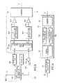
- FIG. 1is a block diagram of a Chireix architecture amplifier subsystem
- FIG. 2is a block diagram of an amplifier system using the subsystem of FIG. 1 and a predistortion subsystem;
- FIGS. 3A and 3Billustrate characteristics of distorted system output signals superimposed on the desired system output signal characteristics
- FIGS. 4A and 4Billustrate the characteristics of FIGS. 3A and 3B with characteristics of predistorted input signals
- FIG. 5is a detailed block diagram of an amplifier subsystem according to the invention incorporating the Chireix amplifier subsystem of FIG. 1 with a predistortion subsystem;
- FIG. 6is a block diagram of a signal processing system according to another embodiment of the invention.
- a signal decomposer 20receives an input complex baseband signal 30 .
- Phase modulated RF signals 80 A, 80 Bare produced after the decomposed output of the decomposer 20 are phase modulated by phase modulation circuitry 85 A, 85 B. These phase modulated signals 80 A, 80 B are received by power amplifiers 90 A, 90 B. The phase modulated signals are thus amplified by the power amplifiers 90 A, 90 B and are received by a signal combiner 100 .
- the system output signal 110(an RF signal corresponding to the input baseband signal 30 ) is output from the combiner 100 and is an amplified and modulated version of the input signal 30 .
- Phase modulation of the phase modulated signals 80 A, 80 Bis executed after the signal decomposer 20 separates input signal 30 into at least two components. These at least two components, after phase modulation, are the signals 80 A, 80 B.
- the Chireix architecture amplifier subsystem 10has been known to introduce distortions in the system output signal 110 .
- a predistortion subsystem 120is provided. Referring to FIG. 2 , the predistortion subsystem 120 receives the input signal 30 and produces a predistorted signal 130 . The predistorted signal 130 is received by the amplifier subsystem 10 . The amplifier subsystem then produces the system output signal 110 .
- the distortions for which the predistortion subsystem is to compensatemay come as a phase distortion, a magnitude distortion, or as a combination of both. It has been found that, without predistortion, the system output signal has an amplitude modulation (AM) envelope that is not equal to the expected and desired AM envelope. Furthermore, the phase modulation (PM) of the system output signal 110 , if predistortion is not present, deviates from the expected and desired PM. Experiments have found that the AM distortion or error (magnitude distortion) of the system output signal 110 depends on the AM of the input signal. Also, it has been found that the PM distortion (or phase distortion) of the system output signal 110 depends on the AM of the input signal 30 .
- AMamplitude modulation
- PMphase modulation
- FIGS. 3A , 3 Bare provided.
- the desired AM characteristic 140is not followed by the resulting AM 150 of the system output signal.
- the resulting PM 160 of the system output signaldeviates from the desired PM characteristic (in this case 0°) as the AM varies.
- the desired AM predistortion output characteristic 170 and the desired PM predistortion output characteristic 180illustrated are the desired AM predistortion output characteristic 170 and the desired PM predistortion output characteristic 180 .
- the resulting AM characteristic 150(with no predistortion) is distorted, then predistortion which results in the AM predistorted output characteristic 170 should produce the desired PM characteristic 140 .
- the distortion of the resulting PM characteristic 160(with no predistortion) can be compensated for by providing predistortion that results in a PM predistorted output characteristic 180 .
- the resulting system output signalshould be generally free of AM/AM and AM/PM distortions.
- the predistortion modificationdefined as any deliberate distortion which has been applied or is to be applied to the input signal to change at least one original characteristic of the input signal, can take many forms.
- Two specific types of predistortion, phase predistortion and magnitude predistortionare currently envisioned although other types are possible. These two types, separately or together, can make up the predistortion modification. In some applications, only a magnitude type predistortion modification may be required while in others only a phase type predistortion is required.
- the predistortion discussion abovecan be implemented in the predistortion subsystem 120 illustrated in FIG. 2 .
- a more detailed illustration of the predistortion subsystem 120is presented in FIG. 5 . While an analog implementation of the predistortion subsystem is possible, it has been found that a digital implementation was simpler to achieve.
- the predistortion subsystem 120has 4 main components: a Cartesian to polar conversion unit 190 , a magnitude lookup table 200 (magnitude LUT), a phase lookup table 210 (phase LUT), and an adder 220 .
- the input signalis received by the conversion unit 190 and is converted from Cartesian coordinates to polar coordinates.
- the converted signalis then received and used by the lookup tables 200 , 210 to determine the proper amount of predistortion to be applied.
- the phase lookup table 210provides the amount of phase distortion to be added to the phase value 214 by way of adder 220 .
- the magnitude LUT 200provides the desired value of the predistorted magnitude. This desired value is then substituted with the magnitude value received from the conversion unit 190 .
- the magnitude value 212 received from the conversion unit 190is determinative of the amount of predistortion required for both magnitude and phase.
- the predistorted signalis then passed on to the amplifier subsystem 10 .
- the input signal 30is a digital signal having a digital representation of its AM envelope and of its PM.
- the conversion unit 190while present, is not necessary but merely convenient and makes the predistortion easier to accomplish.
- the signalis now represented by two values—a magnitude value 212 and a phase value 214 .
- the magnitude of the signalis determinative of the distortion of the system output signal.
- FIG. 5illustrates the different signal paths followed by these two values—one path for the magnitude value 212 and a second path for the phase value 214 .
- the magnitude value 212can be easily replaced by the desired magnitude value. This is done by way of magnitude lookup table block 200 .
- the lookup table internal to the magnitude lookup table block 200represents an input/output relationship with the input being the desired magnitude and the output being the predistorted signal magnitude.
- the magnitude LUT block 200has a table entry with an input value of 0.5 and an output value of 0.4, then if the undistorted magnitude value received by the magnitude LUT block 200 is 0.5, then this value is replaced with 0.4 as the output of the magnitude LUT block 200 .
- the magnitude of the undistorted signalis therefore replaced with the desired predistorted magnitude.
- phase lookup table block 210Similar to the above, the phase value of the converted input signal is adjusted as well. As can be seen in FIG. 5 , the magnitude value 212 is also received by the phase lookup table block 210 . The phase lookup table block 210 , based on the magnitude value, determines the proper amount of phase adjustment and adds this phase adjustment to the phase value 214 by way of the adder 220 . The phase lookup table block 210 also has an lookup table resident within the phase LUT block 210 that details the appropriate phase adjustments for given magnitude values.
- the magnitude LUTreplaces a desired value for the received magnitude
- the magnitude LUTmay provide a corrective value to the received magnitude.
- This corrective valuecan, depending on the implementation, be an additive or a multiplicative corrective value.
- the lookup table entries found in the lookup tables internal to the magnitude LUT block 200 and the phase LUT block 210may be based on experimentally derived data. As an example of how such experimentally derived data can be found, a desired output value from the amplifier subsystem 10 is first chosen. Then, an input signal to the amplifier subsystem 10 is adjusted until the desired output value is achieved. That is, if it is found that a value of q input to the amplifier subsystem 10 produces a desired amplifier output value of t, then, in the lookup table the value of q is entered as the value to be output from the lookup table block for a desired value t. For the magnitude table, the desired amplifier output value is entered as the value to be input to the lookup table block. As such, if a value of t is input to the magnitude LUT block 200 , a value of q is output from the block 200 to produce an amplifier output value of t.
- the table entriescan be found by adjustments of the entries until the desired output is obtained.
- phase tableFor the phase table, if experimentation shows that an input magnitude 214 of r results in a distortion of s in the phase, then the corrective value can easily be found. As such, the phase table would, for an input value 212 corresponding to the magnitude r, contain the corrective value. Again, the table entries can be adjusted.
- lookup tablesmay have the following entries:
- the magnitude and phase correction conceptcan be further refined, if applicable, by using a polynomial to determine the required predistortion. If a mathematical relationship is found to approximate or equate the relationship between the input (such as input magnitude or input phase) and the required predistortion, this mathematical relationship can be used to generate the predistortion.
- interpolationmay be used to formulate the required predistortion value.
- the interpolationmay be linear for simplicity in implementation or it may be a more complex form of interpolation.
- more complex interpolation schemessuch as those using different weight values for different table entries, may be used.
- the circuit of FIG. 5contains features relating to one embodiment of the amplifier subsystem.
- the signal decomposer 20 of FIG. 1contains a phasor fragmentation engine 20 A.
- the fragmentation engine 20 Areceives the magnitude (M) and phase ( ⁇ )) representing the predistorted signal.
- the phasor fragmentation engine 20 Adeconstructs a predetermined modulation waveform (the predistorted signal) into signal components which are of equal magnitude. Further information regarding the phasor fragmentation engines may be found in the applicant's co-pending application U.S. application Ser. No.
- these signal componentsare denoted by angles ⁇ and ⁇ . These components are each received by phase modulation and filtering blocks 60 A, 60 B which process the components to produce phase modulated and filtered versions of the components.
- the signal component 70 Ais an RF signal with phase ⁇ while signal component 70 B is an RF signal with phase ⁇ .
- These components 70 A, 70 Bare then amplified by amplifiers 90 A, 90 B. The amplified components are then recombined using combiner 100 .
- Signal decomposition methods other than the phasor fragmentation referred to abovemay also be used by the signal decomposer 20 .
- switch mode amplifiersare preferred for the amplifiers 90 A, 90 B.
- Such switch mode amplifiersspecifically Class D and Class F power amplifiers, provide low output impedances that allow higher amplification efficiencies.
- a co-pending application filed on Oct. 16, 2002 and having U.S. Ser. No. 10/272,725 entitled CHIREIX ARCHITECTURE USING LOW IMPEDANCE AMPLIFIERSprovides further information on the desirable components and is hereby incorporated by reference.
- Such types of amplifiersare not required for the invention to function but they have been found to provide performance at a desirable level.
- FIG. 5illustrates a parallel implementation of the predistortion
- a serial implementationis possible.
- the magnitude predistortionis applied in parallel with the phase predistortion. While this is preferable for purposes of speed, it is also possible to have cascaded predistortion stages.
- a magnitude predistortioncan be applied to the input signal after first applying a phase predistortion.
- the predistortion subsystem 10does not linearize a power amplifier as is well-known in the field. Instead, the predistortion subsystem linearizes a whole power amplifier system—the output of the whole amplifier system is linearized and not simply the output of a single amplifier. Also, unlike the linearizing systems for power amplifiers that are currently known, the amplifier system discussed in this document compensates for distortions that mostly occur at mid signal amplitudes. Current single amplifier linearization systems linearize distortions that occur at large signal amplitudes.
- the inventionmay be applied to any signal processing system which decomposes a signal into components and recombines them. It has been found that signal combiners (block 100 in FIG. 1 ) invariably cause distortions. These combiners use addition to recombine the components and improper signal addition, such as when recombining sinusoidal components, has been found to be one cause of the distortions in the system output signal. In the above embodiment, the phasor fragmentation engine decomposes the incoming signal into vectors and the improper addition of these vectors by the combiner 100 lead to distortions in the output signal.
- the predistortion subsystem 120predistorts an incoming signal 30 and compensates for distortions introduced in the system output signal 110 by the improper or imperfect recombining of the input signals components.
- These componentsare produced by the signal decomposer 20 and are separately processed by signal component processor blocks 75 A, 75 B.
- the processing executed by the blocks 75 A, 75 Bmay take the form of amplification (as in the embodiment above), phase modulation, a combination of the two, or any other signal processing which may be desired.
- each of the signal components illustrated in FIG. 5may be separately phase modulated in addition to being amplified by amplifiers 90 A- 90 B.
- the phase modulationmay be accomplished separately or be incorporated in the signal decomposer or, as contemplated for the implementation illustrated in FIG. 5 , incorporated into the modulation and filtering blocks 60 A, 60 B.
- the signal processing subsystem 10 Areceives the predistorted signal from the predistortion subsystem 120 . After being received, the predistorted signal is decomposed by the signal decomposer 20 into components. These components are then separately processed by the signal component processor blocks 75 A, 75 B and are then recombined by the recombiner 100 .
- One advantage using the above inventionis that it allows less stringent tolerances to be used for the system components. Previously, components had to be substantially matched so that signal processing could produce acceptable results. By using the above invention, less than substantially matched components may be used together. Errors due to a mismatch may be measured and compensated for by the predistortion subsystem.
Landscapes
- Physics & Mathematics (AREA)
- Nonlinear Science (AREA)
- Engineering & Computer Science (AREA)
- Power Engineering (AREA)
- Amplifiers (AREA)
Abstract
Description
- a predistortion subsystem for receiving said input signal and for producing a predistorted signal by applying a deliberate predistortion to said input signal; and
- a signal processing subsystem receiving and processing said predistorted signal and producing a system output signal,
wherein - said predistortion subsystem distorts said input signal to compensate for distortions in said system output signal;
- said signal processing subsystem decomposes said predistorted signal into separate components, each of said separate components being processed separately; and
- said processing subsystem combines said components after processing to produce said system output signal.
- a) receiving said input signal
- b) applying a deliberate predistortion to said input signal to result in a predistorted signal
- c) decomposing said predistorted signal into at least two component signals
- d) combining said at least two component signals to produce said system output signal.
- AM (amplitude modulation) refers to the AM of an RF (radio frequency) signal and is equal to the magnitude of the RF signal's complex base band equivalent
- PM (phase modulation) refers to the PM of an RF signal and is equal to the phase of the RF signal's complex base band equivalent.
| Input AM Magnitude | AM Predistortion Value | ||
| IN1 | AM1 | ||
| IN2 | AM2 | ||
| IN3 | AM3 | ||
| Input AM Magnitude | Phase Predistortion Adjustment | ||
| IN1 | PM1 | ||
| IN2 | PM2 | ||
| IN3 | PM3 | ||
Thus, if the amplifier system detects the input AM magnitude as IN1, then the AM predistorted magnitude should have a value of AM1 and the phase predistortion should have an added value of PM1. Thus, for predistortion, the input AM magnitude of IN1 is replaced by a value of AM1. Similarly, if the input phase is PM0, then for an input AM magnitude of IN1, then the resulting predistorted phase should be PM0+PM1.
Claims (19)
Priority Applications (7)
| Application Number | Priority Date | Filing Date | Title |
|---|---|---|---|
| US10/613,355US7453952B2 (en) | 2003-07-03 | 2003-07-03 | Predistortion circuit for a transmit system |
| US10/641,370US7409193B2 (en) | 2003-07-03 | 2003-08-13 | Predistortion circuit for a transmit system |
| JP2006517918AJP2007525867A (en) | 2003-07-03 | 2004-06-30 | Adaptive predistortion for transmission systems |
| PCT/CA2004/000972WO2005004323A1 (en) | 2003-07-03 | 2004-06-30 | Adaptive predistortion for a transmit system |
| EP04737911.0AEP1645028B1 (en) | 2003-07-03 | 2004-06-30 | Adaptive predistortion for a transmit system |
| KR1020067000173AKR101122985B1 (en) | 2003-07-03 | 2004-06-30 | Adaptive predistortion for a transmit system |
| US12/167,217US7953378B2 (en) | 2003-07-03 | 2008-07-02 | Predistortion circuit for a transmit system |
Applications Claiming Priority (1)
| Application Number | Priority Date | Filing Date | Title |
|---|---|---|---|
| US10/613,355US7453952B2 (en) | 2003-07-03 | 2003-07-03 | Predistortion circuit for a transmit system |
Related Child Applications (2)
| Application Number | Title | Priority Date | Filing Date |
|---|---|---|---|
| US10/641,370Continuation-In-PartUS7409193B2 (en) | 2003-07-03 | 2003-08-13 | Predistortion circuit for a transmit system |
| US10/641,370ContinuationUS7409193B2 (en) | 2003-07-03 | 2003-08-13 | Predistortion circuit for a transmit system |
Publications (2)
| Publication Number | Publication Date |
|---|---|
| US20050002470A1 US20050002470A1 (en) | 2005-01-06 |
| US7453952B2true US7453952B2 (en) | 2008-11-18 |
Family
ID=33552674
Family Applications (1)
| Application Number | Title | Priority Date | Filing Date |
|---|---|---|---|
| US10/613,355Expired - LifetimeUS7453952B2 (en) | 2003-07-03 | 2003-07-03 | Predistortion circuit for a transmit system |
Country Status (1)
| Country | Link |
|---|---|
| US (1) | US7453952B2 (en) |
Cited By (4)
| Publication number | Priority date | Publication date | Assignee | Title |
|---|---|---|---|---|
| US20080014866A1 (en)* | 2006-07-12 | 2008-01-17 | Lipowski Joseph T | Transceiver architecture and method for wireless base-stations |
| US20080268795A1 (en)* | 2003-07-03 | 2008-10-30 | Zarbana Digital Fund, Llc | Predistortion circuit for a transmit system |
| US20100214018A1 (en)* | 2003-07-03 | 2010-08-26 | Saed Aryan | Adaptive predistortion for a transmit system |
| US20130321084A1 (en)* | 2011-12-15 | 2013-12-05 | Telefonaktiebolaget L M Ericsson (Publ) | Apparatus and method for use with an amplifier circuit |
Families Citing this family (26)
| Publication number | Priority date | Publication date | Assignee | Title |
|---|---|---|---|---|
| US7801244B2 (en) | 2002-05-16 | 2010-09-21 | Rf Micro Devices, Inc. | Am to AM correction system for polar modulator |
| US7991071B2 (en) | 2002-05-16 | 2011-08-02 | Rf Micro Devices, Inc. | AM to PM correction system for polar modulator |
| US7551686B1 (en)* | 2004-06-23 | 2009-06-23 | Rf Micro Devices, Inc. | Multiple polynomial digital predistortion |
| US7529523B1 (en) | 2004-08-23 | 2009-05-05 | Rf Micro Devices, Inc. | N-th order curve fit for power calibration in a mobile terminal |
| US7355470B2 (en) | 2006-04-24 | 2008-04-08 | Parkervision, Inc. | Systems and methods of RF power transmission, modulation, and amplification, including embodiments for amplifier class transitioning |
| US7327803B2 (en) | 2004-10-22 | 2008-02-05 | Parkervision, Inc. | Systems and methods for vector power amplification |
| US8224265B1 (en) | 2005-06-13 | 2012-07-17 | Rf Micro Devices, Inc. | Method for optimizing AM/AM and AM/PM predistortion in a mobile terminal |
| US9106316B2 (en)* | 2005-10-24 | 2015-08-11 | Parkervision, Inc. | Systems and methods of RF power transmission, modulation, and amplification |
| US8334722B2 (en)* | 2007-06-28 | 2012-12-18 | Parkervision, Inc. | Systems and methods of RF power transmission, modulation and amplification |
| US20130078934A1 (en) | 2011-04-08 | 2013-03-28 | Gregory Rawlins | Systems and Methods of RF Power Transmission, Modulation, and Amplification |
| US7911272B2 (en)* | 2007-06-19 | 2011-03-22 | Parkervision, Inc. | Systems and methods of RF power transmission, modulation, and amplification, including blended control embodiments |
| GB2432981B (en)* | 2005-11-30 | 2007-12-27 | Motorola Inc | Apparatus and method for amplitude variation reduction of a signal |
| US7877060B1 (en) | 2006-02-06 | 2011-01-25 | Rf Micro Devices, Inc. | Fast calibration of AM/PM pre-distortion |
| US7962108B1 (en) | 2006-03-29 | 2011-06-14 | Rf Micro Devices, Inc. | Adaptive AM/PM compensation |
| US7782978B2 (en)* | 2006-04-13 | 2010-08-24 | Harris Corporation | Phase correction of a constant envelope signal without introducing amplitude modulation |
| US7937106B2 (en) | 2006-04-24 | 2011-05-03 | ParkerVision, Inc, | Systems and methods of RF power transmission, modulation, and amplification, including architectural embodiments of same |
| US8031804B2 (en)* | 2006-04-24 | 2011-10-04 | Parkervision, Inc. | Systems and methods of RF tower transmission, modulation, and amplification, including embodiments for compensating for waveform distortion |
| US7689182B1 (en) | 2006-10-12 | 2010-03-30 | Rf Micro Devices, Inc. | Temperature compensated bias for AM/PM improvement |
| US7620129B2 (en)* | 2007-01-16 | 2009-11-17 | Parkervision, Inc. | RF power transmission, modulation, and amplification, including embodiments for generating vector modulation control signals |
| US8009762B1 (en) | 2007-04-17 | 2011-08-30 | Rf Micro Devices, Inc. | Method for calibrating a phase distortion compensated polar modulated radio frequency transmitter |
| WO2008144017A1 (en) | 2007-05-18 | 2008-11-27 | Parkervision, Inc. | Systems and methods of rf power transmission, modulation, and amplification |
| WO2008156800A1 (en) | 2007-06-19 | 2008-12-24 | Parkervision, Inc. | Combiner-less multiple input single output (miso) amplification with blended control |
| WO2010026560A2 (en)* | 2008-09-08 | 2010-03-11 | Nxp B.V. | Predistortion unit and method of predistorting signals |
| US8489042B1 (en) | 2009-10-08 | 2013-07-16 | Rf Micro Devices, Inc. | Polar feedback linearization |
| KR20140034895A (en) | 2011-06-02 | 2014-03-20 | 파커비전, 인크. | Antenna control |
| CN106415435B (en) | 2013-09-17 | 2020-08-11 | 帕克维辛股份有限公司 | Method, apparatus, and system for presenting information-carrying time functions |
Citations (40)
| Publication number | Priority date | Publication date | Assignee | Title |
|---|---|---|---|---|
| US5650758A (en) | 1995-11-28 | 1997-07-22 | Radio Frequency Systems, Inc. | Pipelined digital predistorter for a wideband amplifier |
| US5699383A (en) | 1995-03-06 | 1997-12-16 | Nec Corporation | High-power linear amplification using periodically updated amplitude and phase correction values |
| US5880633A (en) | 1997-05-08 | 1999-03-09 | Motorola, Inc. | High efficiency power amplifier |
| EP0930699A1 (en) | 1997-12-19 | 1999-07-21 | Lucent Technologies Inc. | Feed forward amplifier improvement |
| US5990738A (en)* | 1998-06-19 | 1999-11-23 | Datum Telegraphic Inc. | Compensation system and methods for a linear power amplifier |
| US6043707A (en) | 1999-01-07 | 2000-03-28 | Motorola, Inc. | Method and apparatus for operating a radio-frequency power amplifier as a variable-class linear amplifier |
| US6054896A (en) | 1998-12-17 | 2000-04-25 | Datum Telegraphic Inc. | Controller and associated methods for a linc linear power amplifier |
| US6072364A (en) | 1997-06-17 | 2000-06-06 | Amplix | Adaptive digital predistortion for power amplifiers with real time modeling of memoryless complex gains |
| US6075412A (en) | 1998-10-13 | 2000-06-13 | Ophir Rf, Inc. | Linearization for power amplifiers |
| US6141390A (en) | 1997-05-05 | 2000-10-31 | Glenayre Electronics, Inc. | Predistortion in a linear transmitter using orthogonal kernels |
| US6147553A (en)* | 1998-03-06 | 2000-11-14 | Fujant, Inc. | Amplification using amplitude reconstruction of amplitude and/or angle modulated carrier |
| WO2001005026A1 (en) | 1999-07-13 | 2001-01-18 | Pmc-Sierra, Inc. | A wideband digital predistortion linearizer for nonlinear amplifiers |
| US6208207B1 (en) | 1999-05-05 | 2001-03-27 | Simon Fraser University | Adaptive linearizer for RF power amplifiers |
| US6211733B1 (en) | 1999-10-22 | 2001-04-03 | Powerwave Technologies, Inc. | Predistortion compensation for a power amplifier |
| US6215354B1 (en)* | 1998-03-06 | 2001-04-10 | Fujant, Inc. | Closed loop calibration for an amplitude reconstruction amplifier |
| US6246286B1 (en) | 1999-10-26 | 2001-06-12 | Telefonaktiebolaget Lm Ericsson | Adaptive linearization of power amplifiers |
| WO2001056146A1 (en) | 2000-01-26 | 2001-08-02 | Nokia Corporation | Method and system for compensating non-linearities and time-varying changes of a transfer function acting on an input signal |
| US20010054974A1 (en) | 2000-01-26 | 2001-12-27 | Wright Andrew S. | Low noise wideband digital predistortion amplifier |
| EP1170858A2 (en) | 2000-06-21 | 2002-01-09 | Matsushita Electric Industrial Co., Ltd. | Linear amplifying equipment |
| US6342810B1 (en) | 1999-07-13 | 2002-01-29 | Pmc-Sierra, Inc. | Predistortion amplifier system with separately controllable amplifiers |
| US20020034260A1 (en) | 2000-09-15 | 2002-03-21 | Lg Electronics Inc. | Adaptive predistortion transmitter |
| US20020047745A1 (en)* | 2000-06-22 | 2002-04-25 | Kolanek James C. | Management of internal signal levels and control of the net gain for a linc amplifier |
| US6388518B1 (en) | 2000-08-30 | 2002-05-14 | Hitachi Kokusai Electric Inc. | Distortion compensation apparatus |
| US20020101937A1 (en) | 1998-06-26 | 2002-08-01 | Franklin P. Antonio | Predistortion technique for high power amplifiers |
| US20020159532A1 (en)* | 2001-03-23 | 2002-10-31 | Icefyre Semiconductor Corporation | Computational circuits and methods for signal deconstruction/reconstruction in wireless transceivers |
| EP1313278A1 (en) | 2000-07-20 | 2003-05-21 | Huawei Technologies Co., Ltd. | Method and apparatus for adaptive digital predistortion in a radio transmitter |
| US6734731B2 (en) | 2001-06-28 | 2004-05-11 | Simon Fraser University | Self-calibrated power amplifier linearizers |
| US6737914B2 (en)* | 2001-12-07 | 2004-05-18 | 4D Connect, Inc. | Removing effects of gain and phase mismatch in a linear amplification with nonlinear components (LINC) system |
| US6836183B2 (en) | 2002-10-16 | 2004-12-28 | Icefyre Semiconductor Corporation | Chireix architecture using low impedance amplifiers |
| US20050003770A1 (en)* | 2003-07-03 | 2005-01-06 | Icefyre Semiconductor Corporation | Predistortion circuit for a transmit system |
| US20050001677A1 (en) | 2003-07-03 | 2005-01-06 | Icefrye Semiconductor Corporation. | Adaptive predistortion for a transmit system |
| US20050001678A1 (en) | 2003-07-03 | 2005-01-06 | Icefrye Semiconductor Corporation. | Adaptive predistortion for a transmit system with gain, phase and delay adjustments. |
| US6904267B2 (en) | 2001-08-30 | 2005-06-07 | Hitachi Kokusai Electric Inc. | Amplifying device |
| US20050162225A1 (en) | 2004-01-28 | 2005-07-28 | Ntt Docomo, Inc | Multi-band look-up table type predistorter |
| US6940916B1 (en) | 2000-01-27 | 2005-09-06 | Pmc-Sierra, Inc. | Wideband analog quadrature modulator/demodulator with pre-compensation/post-compensation correction |
| US6943627B2 (en) | 2001-08-28 | 2005-09-13 | Telefonaktiebolaget Lm Ericsson (Publ) | Calibration of an adaptive signal conditioning system |
| US6980604B2 (en) | 2001-01-25 | 2005-12-27 | Fujitsu Limited | Transmission device and transmission method |
| US6985704B2 (en) | 2002-05-01 | 2006-01-10 | Dali Yang | System and method for digital memorized predistortion for wireless communication |
| US20060109052A1 (en)* | 2003-07-03 | 2006-05-25 | Aryan Saed | Adaptive predistortion for a transmit system |
| US7127005B2 (en)* | 2001-03-23 | 2006-10-24 | James Stuart Wight | Computational circuits and methods for processing modulated signals having non-constant envelopes |
- 2003
- 2003-07-03USUS10/613,355patent/US7453952B2/ennot_activeExpired - Lifetime
Patent Citations (46)
| Publication number | Priority date | Publication date | Assignee | Title |
|---|---|---|---|---|
| US5699383A (en) | 1995-03-06 | 1997-12-16 | Nec Corporation | High-power linear amplification using periodically updated amplitude and phase correction values |
| US5650758A (en) | 1995-11-28 | 1997-07-22 | Radio Frequency Systems, Inc. | Pipelined digital predistorter for a wideband amplifier |
| US6141390A (en) | 1997-05-05 | 2000-10-31 | Glenayre Electronics, Inc. | Predistortion in a linear transmitter using orthogonal kernels |
| US5880633A (en) | 1997-05-08 | 1999-03-09 | Motorola, Inc. | High efficiency power amplifier |
| US6072364A (en) | 1997-06-17 | 2000-06-06 | Amplix | Adaptive digital predistortion for power amplifiers with real time modeling of memoryless complex gains |
| EP0930699A1 (en) | 1997-12-19 | 1999-07-21 | Lucent Technologies Inc. | Feed forward amplifier improvement |
| US6147553A (en)* | 1998-03-06 | 2000-11-14 | Fujant, Inc. | Amplification using amplitude reconstruction of amplitude and/or angle modulated carrier |
| US6215354B1 (en)* | 1998-03-06 | 2001-04-10 | Fujant, Inc. | Closed loop calibration for an amplitude reconstruction amplifier |
| US5990738A (en)* | 1998-06-19 | 1999-11-23 | Datum Telegraphic Inc. | Compensation system and methods for a linear power amplifier |
| US20020101937A1 (en) | 1998-06-26 | 2002-08-01 | Franklin P. Antonio | Predistortion technique for high power amplifiers |
| US6075412A (en) | 1998-10-13 | 2000-06-13 | Ophir Rf, Inc. | Linearization for power amplifiers |
| US6054896A (en) | 1998-12-17 | 2000-04-25 | Datum Telegraphic Inc. | Controller and associated methods for a linc linear power amplifier |
| US6043707A (en) | 1999-01-07 | 2000-03-28 | Motorola, Inc. | Method and apparatus for operating a radio-frequency power amplifier as a variable-class linear amplifier |
| US6208207B1 (en) | 1999-05-05 | 2001-03-27 | Simon Fraser University | Adaptive linearizer for RF power amplifiers |
| US6342810B1 (en) | 1999-07-13 | 2002-01-29 | Pmc-Sierra, Inc. | Predistortion amplifier system with separately controllable amplifiers |
| WO2001005026A1 (en) | 1999-07-13 | 2001-01-18 | Pmc-Sierra, Inc. | A wideband digital predistortion linearizer for nonlinear amplifiers |
| US6211733B1 (en) | 1999-10-22 | 2001-04-03 | Powerwave Technologies, Inc. | Predistortion compensation for a power amplifier |
| US6246286B1 (en) | 1999-10-26 | 2001-06-12 | Telefonaktiebolaget Lm Ericsson | Adaptive linearization of power amplifiers |
| WO2001056146A1 (en) | 2000-01-26 | 2001-08-02 | Nokia Corporation | Method and system for compensating non-linearities and time-varying changes of a transfer function acting on an input signal |
| US20010054974A1 (en) | 2000-01-26 | 2001-12-27 | Wright Andrew S. | Low noise wideband digital predistortion amplifier |
| US6940916B1 (en) | 2000-01-27 | 2005-09-06 | Pmc-Sierra, Inc. | Wideband analog quadrature modulator/demodulator with pre-compensation/post-compensation correction |
| EP1170858A2 (en) | 2000-06-21 | 2002-01-09 | Matsushita Electric Industrial Co., Ltd. | Linear amplifying equipment |
| US20020047745A1 (en)* | 2000-06-22 | 2002-04-25 | Kolanek James C. | Management of internal signal levels and control of the net gain for a linc amplifier |
| EP1313278A1 (en) | 2000-07-20 | 2003-05-21 | Huawei Technologies Co., Ltd. | Method and apparatus for adaptive digital predistortion in a radio transmitter |
| US6388518B1 (en) | 2000-08-30 | 2002-05-14 | Hitachi Kokusai Electric Inc. | Distortion compensation apparatus |
| US20020034260A1 (en) | 2000-09-15 | 2002-03-21 | Lg Electronics Inc. | Adaptive predistortion transmitter |
| US6980604B2 (en) | 2001-01-25 | 2005-12-27 | Fujitsu Limited | Transmission device and transmission method |
| US7127005B2 (en)* | 2001-03-23 | 2006-10-24 | James Stuart Wight | Computational circuits and methods for processing modulated signals having non-constant envelopes |
| US20020159532A1 (en)* | 2001-03-23 | 2002-10-31 | Icefyre Semiconductor Corporation | Computational circuits and methods for signal deconstruction/reconstruction in wireless transceivers |
| US6734731B2 (en) | 2001-06-28 | 2004-05-11 | Simon Fraser University | Self-calibrated power amplifier linearizers |
| US6943627B2 (en) | 2001-08-28 | 2005-09-13 | Telefonaktiebolaget Lm Ericsson (Publ) | Calibration of an adaptive signal conditioning system |
| US6904267B2 (en) | 2001-08-30 | 2005-06-07 | Hitachi Kokusai Electric Inc. | Amplifying device |
| US6737914B2 (en)* | 2001-12-07 | 2004-05-18 | 4D Connect, Inc. | Removing effects of gain and phase mismatch in a linear amplification with nonlinear components (LINC) system |
| US6985704B2 (en) | 2002-05-01 | 2006-01-10 | Dali Yang | System and method for digital memorized predistortion for wireless communication |
| US6836183B2 (en) | 2002-10-16 | 2004-12-28 | Icefyre Semiconductor Corporation | Chireix architecture using low impedance amplifiers |
| US20050001677A1 (en) | 2003-07-03 | 2005-01-06 | Icefrye Semiconductor Corporation. | Adaptive predistortion for a transmit system |
| US6975167B2 (en)* | 2003-07-03 | 2005-12-13 | Icefyre Semiconductor Corporation | Adaptive predistortion for a transmit system with gain, phase and delay adjustments |
| US20050001678A1 (en) | 2003-07-03 | 2005-01-06 | Icefrye Semiconductor Corporation. | Adaptive predistortion for a transmit system with gain, phase and delay adjustments. |
| US7015752B2 (en)* | 2003-07-03 | 2006-03-21 | Icefyre Semiconductor, Inc. | Adaptive predistortion for a transmit system with gain, phase and delay adjustments |
| US7026871B2 (en)* | 2003-07-03 | 2006-04-11 | Icefyre Semiconductor, Inc. | Adaptive predistortion for a transmit system |
| US7026872B2 (en)* | 2003-07-03 | 2006-04-11 | Icefyre Semiconductor, Inc. | Adaptive predistortion for a transmit system with gain, phase and delay adjustments |
| US7034613B2 (en)* | 2003-07-03 | 2006-04-25 | Icefyre Semiconductor, Inc. | Adaptive predistortion for transmit system with gain, phase and delay adjustments |
| US20060109052A1 (en)* | 2003-07-03 | 2006-05-25 | Aryan Saed | Adaptive predistortion for a transmit system |
| US7068101B2 (en)* | 2003-07-03 | 2006-06-27 | Icefyre Semiconductor Corporation | Adaptive predistortion for a transmit system |
| US20050003770A1 (en)* | 2003-07-03 | 2005-01-06 | Icefyre Semiconductor Corporation | Predistortion circuit for a transmit system |
| US20050162225A1 (en) | 2004-01-28 | 2005-07-28 | Ntt Docomo, Inc | Multi-band look-up table type predistorter |
Non-Patent Citations (4)
| Title |
|---|
| Birafane et al., Phase-Only Predistortion for LINC Amplifiers with Chireix-Outphasing Combiners, Jun. 6, 2005, IEEE Transactions on Microwave Theory and Techniques, vol. 53, Issue 6, Part 2, pp. 2240-2250. □□.* |
| Cox, Linear Amplification with Nonlinear Components, Dec. 1974, IEEE Transactions on Communications, vol. 12, Issue 12, pp. 1942-1945.* |
| Faulkner, Michael, Adaptive Linearization Using Predistortion-Experimental Results, May 1994, IEEE Transactions On Vehicular Technology, vol. 43, No. 2, pp. 323-332.* |
| Michael Faulkner; Adaptive Linearization Using Predistortion-Experimental Results, IEEE Transactions on Vehicular Technology; May 1994; pp. 323-332; vol. 43, No. 2. |
Cited By (8)
| Publication number | Priority date | Publication date | Assignee | Title |
|---|---|---|---|---|
| US20080268795A1 (en)* | 2003-07-03 | 2008-10-30 | Zarbana Digital Fund, Llc | Predistortion circuit for a transmit system |
| US20100214018A1 (en)* | 2003-07-03 | 2010-08-26 | Saed Aryan | Adaptive predistortion for a transmit system |
| US7953378B2 (en)* | 2003-07-03 | 2011-05-31 | Zarbana Digital Fund Llc | Predistortion circuit for a transmit system |
| US8248160B2 (en) | 2003-07-03 | 2012-08-21 | Zarbana Digital Fund Llc | Adaptive predistortion for a transmit system |
| US20080014866A1 (en)* | 2006-07-12 | 2008-01-17 | Lipowski Joseph T | Transceiver architecture and method for wireless base-stations |
| US7962174B2 (en)* | 2006-07-12 | 2011-06-14 | Andrew Llc | Transceiver architecture and method for wireless base-stations |
| US20130321084A1 (en)* | 2011-12-15 | 2013-12-05 | Telefonaktiebolaget L M Ericsson (Publ) | Apparatus and method for use with an amplifier circuit |
| US8836421B2 (en)* | 2011-12-15 | 2014-09-16 | Telefonaktiebolaget L M Ericsson (Publ) | Apparatus and method for use with an amplifier circuit |
Also Published As
| Publication number | Publication date |
|---|---|
| US20050002470A1 (en) | 2005-01-06 |
Similar Documents
| Publication | Publication Date | Title |
|---|---|---|
| US7453952B2 (en) | Predistortion circuit for a transmit system | |
| US7409193B2 (en) | Predistortion circuit for a transmit system | |
| US7068101B2 (en) | Adaptive predistortion for a transmit system | |
| US10728066B2 (en) | Modulation agnostic digital hybrid mode power amplifier system and method | |
| US6975167B2 (en) | Adaptive predistortion for a transmit system with gain, phase and delay adjustments | |
| CN102460956B (en) | Efficient Transmitters for Wireless Communications | |
| US8811917B2 (en) | Digital hybrid mode power amplifier system | |
| EP2143209B1 (en) | Digital hybrid mode power amplifier system | |
| US6930547B2 (en) | Linearizing LINC amplifiers using pre-distortion | |
| US8736365B2 (en) | Broadband linearization module and method | |
| EP1645028B1 (en) | Adaptive predistortion for a transmit system | |
| GB2385730A (en) | An apparatus and method for power amplifier linearisation | |
| HK1228604A (en) | Modulation agnostic digital hybrid mode power amplifier system and method | |
| HK1228604A1 (en) | Modulation agnostic digital hybrid mode power amplifier system and method |
Legal Events
| Date | Code | Title | Description |
|---|---|---|---|
| AS | Assignment | Owner name:ICEFYRE SEMICONDUCTOR CORPORATION, CANADA Free format text:ASSIGNMENT OF ASSIGNORS INTEREST;ASSIGNORS:SAED, ARYAN;DECRUYENAERE, JEAN-PAUL RENE;REEL/FRAME:014267/0749 Effective date:20030624 | |
| AS | Assignment | Owner name:ICEFYRE SEMICONDUCTOR, INC.,CANADA Free format text:ASSIGNMENT OF ASSIGNORS INTEREST;ASSIGNOR:ICEFYRE SEMICONDUCTOR CORPORATION;REEL/FRAME:017262/0905 Effective date:20051031 Owner name:ICEFYRE SEMICONDUCTOR, INC., CANADA Free format text:ASSIGNMENT OF ASSIGNORS INTEREST;ASSIGNOR:ICEFYRE SEMICONDUCTOR CORPORATION;REEL/FRAME:017262/0905 Effective date:20051031 | |
| AS | Assignment | Owner name:ZARBANA DIGITAL FUND, LLC,DELAWARE Free format text:ASSIGNMENT OF ASSIGNORS INTEREST;ASSIGNOR:ICEFYRE SEMICONDUCTOR, INC.;REEL/FRAME:017388/0432 Effective date:20051223 Owner name:ZARBANA DIGITAL FUND, LLC, DELAWARE Free format text:ASSIGNMENT OF ASSIGNORS INTEREST;ASSIGNOR:ICEFYRE SEMICONDUCTOR, INC.;REEL/FRAME:017388/0432 Effective date:20051223 | |
| STCF | Information on status: patent grant | Free format text:PATENTED CASE | |
| CC | Certificate of correction | ||
| FPAY | Fee payment | Year of fee payment:4 | |
| FPAY | Fee payment | Year of fee payment:8 | |
| MAFP | Maintenance fee payment | Free format text:PAYMENT OF MAINTENANCE FEE, 12TH YEAR, LARGE ENTITY (ORIGINAL EVENT CODE: M1553); ENTITY STATUS OF PATENT OWNER: LARGE ENTITY Year of fee payment:12 |