US7453661B1 - Servo writing a disk drive with a controlled overlap near the middle diameter of the disk - Google Patents
Servo writing a disk drive with a controlled overlap near the middle diameter of the diskDownload PDFInfo
- Publication number
- US7453661B1 US7453661B1US11/387,343US38734306AUS7453661B1US 7453661 B1US7453661 B1US 7453661B1US 38734306 AUS38734306 AUS 38734306AUS 7453661 B1US7453661 B1US 7453661B1
- Authority
- US
- United States
- Prior art keywords
- servo
- disk
- tracks
- diameter
- write
- Prior art date
- Legal status (The legal status is an assumption and is not a legal conclusion. Google has not performed a legal analysis and makes no representation as to the accuracy of the status listed.)
- Expired - Fee Related, expires
Links
- 238000000034methodMethods0.000claimsabstractdescription45
- 238000012545processingMethods0.000claimsabstractdescription29
- 230000008569processEffects0.000claimsdescription15
- 238000001514detection methodMethods0.000claimsdescription6
- 238000001914filtrationMethods0.000claimsdescription4
- 238000005259measurementMethods0.000description8
- 238000011084recoveryMethods0.000description8
- 230000007704transitionEffects0.000description5
- 238000004519manufacturing processMethods0.000description4
- 238000010420art techniqueMethods0.000description3
- 238000010586diagramMethods0.000description2
- 230000004044responseEffects0.000description2
- 239000004065semiconductorSubstances0.000description2
- 230000001360synchronised effectEffects0.000description2
- 101000606504Drosophila melanogaster Tyrosine-protein kinase-like otkProteins0.000description1
- 230000002411adverseEffects0.000description1
- 238000013459approachMethods0.000description1
- 230000001427coherent effectEffects0.000description1
- 230000000694effectsEffects0.000description1
- 230000004907fluxEffects0.000description1
- 230000000977initiatory effectEffects0.000description1
- 230000010354integrationEffects0.000description1
- 238000012986modificationMethods0.000description1
- 230000004048modificationEffects0.000description1
- 230000000737periodic effectEffects0.000description1
- 230000001902propagating effectEffects0.000description1
Images


Classifications
- G—PHYSICS
- G11—INFORMATION STORAGE
- G11B—INFORMATION STORAGE BASED ON RELATIVE MOVEMENT BETWEEN RECORD CARRIER AND TRANSDUCER
- G11B5/00—Recording by magnetisation or demagnetisation of a record carrier; Reproducing by magnetic means; Record carriers therefor
- G11B5/48—Disposition or mounting of heads or head supports relative to record carriers ; arrangements of heads, e.g. for scanning the record carrier to increase the relative speed
- G11B5/58—Disposition or mounting of heads or head supports relative to record carriers ; arrangements of heads, e.g. for scanning the record carrier to increase the relative speed with provision for moving the head for the purpose of maintaining alignment of the head relative to the record carrier during transducing operation, e.g. to compensate for surface irregularities of the latter or for track following
- G11B5/596—Disposition or mounting of heads or head supports relative to record carriers ; arrangements of heads, e.g. for scanning the record carrier to increase the relative speed with provision for moving the head for the purpose of maintaining alignment of the head relative to the record carrier during transducing operation, e.g. to compensate for surface irregularities of the latter or for track following for track following on disks
- G11B5/59688—Servo signal format patterns or signal processing thereof, e.g. dual, tri, quad, burst signal patterns
- G—PHYSICS
- G11—INFORMATION STORAGE
- G11B—INFORMATION STORAGE BASED ON RELATIVE MOVEMENT BETWEEN RECORD CARRIER AND TRANSDUCER
- G11B5/00—Recording by magnetisation or demagnetisation of a record carrier; Reproducing by magnetic means; Record carriers therefor
- G11B5/48—Disposition or mounting of heads or head supports relative to record carriers ; arrangements of heads, e.g. for scanning the record carrier to increase the relative speed
- G11B5/58—Disposition or mounting of heads or head supports relative to record carriers ; arrangements of heads, e.g. for scanning the record carrier to increase the relative speed with provision for moving the head for the purpose of maintaining alignment of the head relative to the record carrier during transducing operation, e.g. to compensate for surface irregularities of the latter or for track following
- G11B5/596—Disposition or mounting of heads or head supports relative to record carriers ; arrangements of heads, e.g. for scanning the record carrier to increase the relative speed with provision for moving the head for the purpose of maintaining alignment of the head relative to the record carrier during transducing operation, e.g. to compensate for surface irregularities of the latter or for track following for track following on disks
- G11B5/59633—Servo formatting
- G11B5/59638—Servo formatting apparatuses, e.g. servo-writers
- G—PHYSICS
- G11—INFORMATION STORAGE
- G11B—INFORMATION STORAGE BASED ON RELATIVE MOVEMENT BETWEEN RECORD CARRIER AND TRANSDUCER
- G11B5/00—Recording by magnetisation or demagnetisation of a record carrier; Reproducing by magnetic means; Record carriers therefor
- G11B5/48—Disposition or mounting of heads or head supports relative to record carriers ; arrangements of heads, e.g. for scanning the record carrier to increase the relative speed
- G11B5/58—Disposition or mounting of heads or head supports relative to record carriers ; arrangements of heads, e.g. for scanning the record carrier to increase the relative speed with provision for moving the head for the purpose of maintaining alignment of the head relative to the record carrier during transducing operation, e.g. to compensate for surface irregularities of the latter or for track following
- G11B5/596—Disposition or mounting of heads or head supports relative to record carriers ; arrangements of heads, e.g. for scanning the record carrier to increase the relative speed with provision for moving the head for the purpose of maintaining alignment of the head relative to the record carrier during transducing operation, e.g. to compensate for surface irregularities of the latter or for track following for track following on disks
- G11B5/59633—Servo formatting
- G11B5/59661—Spiral servo format
- G—PHYSICS
- G11—INFORMATION STORAGE
- G11B—INFORMATION STORAGE BASED ON RELATIVE MOVEMENT BETWEEN RECORD CARRIER AND TRANSDUCER
- G11B5/00—Recording by magnetisation or demagnetisation of a record carrier; Reproducing by magnetic means; Record carriers therefor
- G11B5/48—Disposition or mounting of heads or head supports relative to record carriers ; arrangements of heads, e.g. for scanning the record carrier to increase the relative speed
- G11B5/58—Disposition or mounting of heads or head supports relative to record carriers ; arrangements of heads, e.g. for scanning the record carrier to increase the relative speed with provision for moving the head for the purpose of maintaining alignment of the head relative to the record carrier during transducing operation, e.g. to compensate for surface irregularities of the latter or for track following
- G11B5/596—Disposition or mounting of heads or head supports relative to record carriers ; arrangements of heads, e.g. for scanning the record carrier to increase the relative speed with provision for moving the head for the purpose of maintaining alignment of the head relative to the record carrier during transducing operation, e.g. to compensate for surface irregularities of the latter or for track following for track following on disks
- G11B5/59633—Servo formatting
- G11B5/59655—Sector, sample or burst servo format
Definitions
- the present inventionrelates to disk drives. More particularly, the present invention relates to servo writing a disk drive with a controlled overlap near the middle diameter of the disk.
- Disk drives for computer systemscomprise a disk for storing data and a head actuated radially over the disk for writing data to and reading data from the disk.
- the headis connected to the distal end of an actuator arm which is rotated about a pivot by a rotary actuator (e.g., a voice coil motor (VCM)).
- VCMvoice coil motor
- the diskis typically divided into a number of concentric, radially spaced tracks, where each track is divided into a number of data sectors.
- the diskis typically accessed a data sector at a time by positioning the head over the track which comprises the target data sector.
- transitionse.g., magnetic transitions
- a closed loop servo systemtypically performs the seeking and tracking operations by controlling the rotary actuator in response to position information generated from the head.
- FIG. 1shows a disk 2 comprising a number of concentric data tracks 4 and a number of embedded servo sectors 6 0 - 6 N .
- Each servo sector 6comprises a preamble 8 , a sync mark 10 , servo data 12 , and servo bursts 14 .
- the preamble 8comprises a periodic pattern which allows proper gain adjustment and timing synchronization of the read signal
- the sync mark 10comprises a special pattern for symbol synchronizing to the servo data 12 .
- the servo data 12comprises identification information, such as sector identification data and a track address.
- the servo control systemreads the track address during seeks to derive a coarse position for the head with respect to the target track.
- the track addressesare recorded using a phase coherent Gray code so that the track addresses can be accurately detected when the head is flying between tracks.
- the servo bursts 14 in the servo sectors 6comprise groups of consecutive transitions (e.g., A, B, C and D bursts) which are recorded at precise intervals and offsets with respect to the track centerline. Fine head position control information is derived from the servo bursts 14 for use in centerline tracking while writing data to and reading data from the target track.
- the embedded servo sectors 6are written to the disk 2 as part of the manufacturing process.
- an external servo writerhas been employed which writes the embedded servo sectors 6 to the disks by processing each head disk assembly (HDA) in an assembly line fashion.
- the external servo writersemploy very precise head positioning mechanics, such as a laser interferometer, for positioning the head at precise radial locations with respect to previously servo-written tracks so as to achieve very high track densities.
- Certain “self-servo writing” techniquehave also been disclosed wherein components internal to the disk drive are employed to perform the servo writing function.
- FIGS. 2A-2Cillustrate a problem that manifests when servo writing the disk 2 using perpendicular magnetic recording.
- the skew angle of the head's write pole 16 as it approaches the inner diametercauses the inner corner of the write pole 16 to “swing out” and overwrite a band 18 of the previously written servo data.
- the overwritten band 18creates a “seam” between adjacent servo sectors, as well as a seam within each servo sector (including the servo bursts 14 ) if multiple revolutions are used to “stitch” together each servo sector 6 i .
- U.S. Pat. No. 6,504,675discloses a disk drive wherein the write pole has a trapezoidal shape in order to reduce the overwrite problem caused by the skew effect.
- the geometry of the trapezoidal shapevaries between each disk drive due to tolerances in manufacturing the head, resulting in undesirable seams in the servo wedges for some percentage of the disk drives.
- manufacturing the write pole with a trapezoidal shapeincreases the manufacturing cost of the head, as well as reduces the surface area of the write pole leading to an undesirable decrease in the strength of the magnetic write flux.
- U.S. Patent Application No. 2004/0061967suggests an alternative solution to the overwrite problem by writing the servo sectors 6 0 - 6 N from the outer diameter of the disk to the middle diameter, and then from the inner diameter to the middle diameter as illustrated in FIGS. 3A-3B .
- a problem with this techniqueis that a gap is created near the middle diameter of the disk ( FIG. 3B ) where the two segments of a servo wedge “meet”. This gap becomes unusable (wasted) surface area reducing format efficiency.
- the seek operation in the servo systemis adversely affected due to the loss of position information over the gap. This problem is exacerbated due to the disk expanding during the servo writing operation requiring a predetermined margin (wider gap) to account for the worst case deviation in the expansion.
- An embodiment of the present inventioncomprises a method of servo writing a disk of a disk drive, the disk drive comprising the disk and a head actuated over the disk.
- Servo sectorsare written to define servo tracks from a first diameter of the disk to substantially a middle diameter of the disk, wherein the first diameter is selected from one of the outer and inner diameter of the disk.
- Servo sectorsare then written to define servo tracks from a second diameter of the disk toward the middle diameter of the disk by positioning the head over a current servo track, reading the current servo track to generate a read signal, processing the read signal to detect a previously written servo sector, and if a previously written servo sector is not detected, then writing servo sectors to the current servo track and positioning the head over a next servo track.
- the step of writing servo sectors from the second diameter of the disk toward the middle diameter of the diskcomprises the step of continuing to write servo sectors to a predetermined number of servo tracks after detecting the previously written servo sector to form a controlled overlap of servo tracks near the middle diameter of the disk.
- an external servo writeris used to servo write the disk.
- a media writeris used to servo write the disk.
- control circuitry internal to the disk driveis used to servo write the disk.
- the step of processing the read signal to detect the previously written servo sectorcomprises the step of comparing the read signal to a predetermined threshold.
- the step of processing the read signal to detect the previously written servo sectorcomprises the steps of filtering the read signal with a low pass filter to generate a filtered read signal, and comparing the filtered read signal to a predetermined threshold.
- the step of processing the read signal to detect the previously written servo sectorcomprises the step of opening a detection window commensurate with the head approaching an expected circumferential location of a servo sector.
- each servo sectorcomprises a track address and the step of writing servo sectors from the second diameter of the disk toward the middle diameter of the disk comprises the step of processing the read signal to detect the track address in the previously written servo sector.
- the track addresses in the previously written servo sectorsare processed to write the servo sectors that form a controlled overlap of servo tracks near the middle diameter of the disk.
- Another embodiment of the present inventioncomprises a disk drive including a disk, a head actuated over the disk, and control circuitry operable to servo write the disk.
- the control circuitryis operable to write servo sectors to define servo tracks from a first diameter of the disk to substantially a middle diameter of the disk, wherein the first diameter is selected from one of the outer and inner diameter of the disk.
- Servo sectorsare then written to define servo tracks from a second diameter of the disk toward the middle diameter of the disk by positioning the head over a current servo track, reading the current servo track to generate a read signal, processing the read signal to detect a previously written servo sector, and if a previously written servo sector is not detected, then writing servo sectors to the current servo track and positioning the head over a next servo track.
- Another embodiment of the present inventioncomprises a method of servo writing a disk of a disk drive, the disk drive comprising the disk and a head actuated over the disk.
- a plurality of seed tracksare written to the disk.
- the seed tracksare then processed to write servo sectors to define servo tracks from a first diameter of the disk to substantially a middle diameter of the disk, wherein the first diameter is selected from one of the outer and inner diameter of the disk.
- the seed tracksare then processed to write servo sectors to define servo tracks from a second diameter of the disk toward the middle diameter of the disk, wherein the second diameter is selected from one of the outer and inner diameter of the disk.
- Another embodiment of the present inventioncomprises a disk drive including a disk having a plurality of seed tracks, a head actuated over the disk, and control circuitry operable to servo write the disk.
- the control circuitryis operable to process the seed tracks to write servo sectors to define servo tracks from a first diameter of the disk to substantially a middle diameter of the disk, wherein the first diameter is selected from one of the outer and inner diameter of the disk.
- the seed tracksare then processed to write servo sectors to define servo tracks from a second diameter of the disk toward the middle diameter of the disk, wherein the second diameter is selected from one of the outer and inner diameter of the disk.
- FIG. 1shows a prior art disk format comprising a plurality of radially spaced, concentric servo tracks defined by a plurality of servo sectors.
- FIGS. 2A-2Cillustrate a prior art technique of servo writing a disk which exhibits an overwrite problem, particularly when employing perpendicular magnetic recording.
- FIGS. 3A-3Cillustrate a prior art technique for overcoming the overwrite problem by servo writing from the outer diameter to the middle diameter and then from the inner diameter to the middle diameter leaving a gap near the middle diameter.
- FIG. 4shows an embodiment of the present invention wherein the servo sectors previously written to the disk are processed in order to write servo sectors that form a controlled overlap of servo tracks near the middle diameter of the disk.
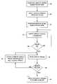
- FIG. 5shows a flow diagram according to an embodiment of the present invention for writing the servo sectors from the outer diameter toward the middle diameter, and from the inner diameter toward the middle diameter until a previously written servo sector is detected.
- FIG. 6Ashows an embodiment of the present invention wherein an external servo writer is used to servo write the disk.
- FIG. 6Bshows an embodiment of the present invention wherein a media writer is used to servo write the disk.
- FIG. 6Cshows an embodiment of the present invention wherein the control circuitry internal to the disk drive is used to servo write the disk.
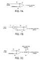
- FIG. 7Ashows circuitry for detecting a previously written servo sector by comparing the read signal to a threshold according to an embodiment of the present invention.
- FIG. 7Bshows circuitry for detecting a previously written servo sector by low pass filtering the read signal and comparing the filtered read signal to a threshold according to an embodiment of the present invention.
- FIG. 7Cshows circuitry for detecting a previously written servo sector by enabling a detection window commensurate with the head approaching an expected circumferential location of a servo sector according to an embodiment of the present invention.
- FIG. 8shows an embodiment of the present invention wherein the track address in a previously written servo sector is used to enable the servo sector detector as well as control the overlap of servo tracks near the middle diameter of the disk.
- FIG. 9Aillustrates an embodiment of the present invention wherein a plurality of seed tracks in the form of spiral tracks are written to the disk for use in writing the servo sectors to the disk.
- FIG. 9Billustrates an embodiment of the present invention wherein each spiral track is written over multiple revolutions of the disk.
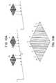
- FIG. 10Ashows an embodiment of the present invention wherein a servo write clock is synchronized by clocking a modulo-N counter relative to when the sync marks in the spiral tracks are detected.
- FIG. 10Bshows an eye pattern generated by reading the spiral track, including the sync marks in the spiral track.
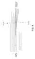
- FIG. 11illustrates writing of servo sectors using a servo write clock generated from reading the spiral tracks.
- FIG. 12Aillustrates an embodiment of the present invention wherein the high frequency signal in the spiral tracks is demodulated by integrating the read signal over a demodulation window and generating the PES relative to a target sync mark and a reference point on the resulting ramp signal.
- FIG. 12Billustrates initiating a seek operation by shifting the demodulation window an integer number of sync marks to generate a non-zero PES.
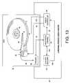
- FIG. 13shows an embodiment of the present invention wherein an external product servo writer is used to process the spiral tracks in order to write the servo sectors to the disk.
- FIG. 14shows an embodiment of the present invention wherein an external spiral servo writer is used to write the spiral tracks, and a plurality of external product servo writers write the servo sectors for the HDAs output by the external spiral servo writer.
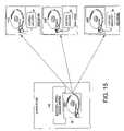
- FIG. 15shows an embodiment of the present invention wherein an external spiral servo writer is used to write the spiral tracks, and the control circuitry within each product disk drive is used to write the servo sectors to the disk.
- FIG. 4shows an embodiment of the present invention as a method of servo writing a disk of a disk drive, the disk drive comprising the disk and a head actuated over the disk.
- Servo sectorsare written to define servo tracks from a first diameter of the disk to substantially a middle diameter of the disk, wherein the first diameter is selected from one of the outer and inner diameter of the disk.
- Servo sectorsare then written to define servo tracks from a second diameter of the disk toward the middle diameter of the disk by positioning the head over a current servo track, reading the current servo track to generate a read signal, processing the read signal to detect a previously written servo sector, and if a previously written servo sector is not detected, then writing servo sectors to the current servo track and positioning the head over a next servo track.
- the step of writing servo sectors from the second diameter of the disk toward the middle diameter of the diskcomprises the step of continuing to write servo sectors to a predetermined number of servo tracks after detecting the previously written servo sector to form a controlled overlap of servo tracks near the middle diameter of the disk. Any suitable number of servo tracks may be written to overlap the previously written servo tracks. Overlapping the servo tracks near the middle diameter of the disk improves format efficiency by effectively eliminating the gap formed when servo writing the disk using the prior art technique shown in FIGS. 3A-3C .
- FIG. 5is a flow diagram according to an embodiment of the present invention for servo writing the disk.
- the headis positioned at the outer diameter of the disk, and at step 20 servo sectors are written to define servo tracks from the outer diameter of the disk to substantially a middle diameter of the disk.
- the headis positioned at the inner diameter of the disk, and at step 24 servo sectors are written to define servo tracks from the inner diameter of the disk toward the middle diameter of the disk.
- the current servo trackis read using the head at step 28 .
- a previously written servo sectoris not detected at the current servo track, then at step 32 servo sectors are written to the current servo track and the head is positioned over a next servo track. This process is repeated until at step 30 a previously written servo sector is detected.
- a predetermined number of servo tracksare written to form a controlled overlap of servo tracks near the middle diameter of the disk.
- the servo tracksare first written from the inner diameter of the disk to the middle diameter, and then from the outer diameter of the disk to the middle diameter.
- FIG. 6Ashows an embodiment of the present invention wherein an external servo writer 36 is used to servo write the disk 2 .
- the disk 2 and head 16are enclosed in a head disk assembly (HDA) 38 .
- the head 16is coupled to the distal end of an actuator arm 40 which is rotated about a pivot by a voice coil motor (VCM) 42 .
- VCMvoice coil motor
- the external servo writer 36generates suitable control signals applied to the VCM 42 while servo writing the disk 2
- the external servo writer 36inserts a push pin into the HDA 38 for use in positioning the actuator arm 40 while servo writing the disk 2 .
- the external servo writer 36comprises suitable circuitry for detecting the position of the actuator arm 40 (e.g., using a laser interferometer) in order to implement a closed loop servo system.
- the external servo writer 36also inserts a clock head into the HDA 38 for use in writing/reading a clock track.
- the clock trackis read during the servo writing process in order to synchronize a servo write clock to the rotation of the disk 2 .
- the external servo writer 36further comprises suitable circuitry for processing a read signal 44 emanating from the head 16 in order to detect the previously written servo sectors while servo writing from the inner diameter toward the middle diameter of the disk 2 .
- FIG. 6Bshows an alternative embodiment of the present invention wherein a media writer 46 is used to servo write one or more of the disks 2 which are then inserted into the HDA 38 of a product disk drive.
- the media writer 46comprises one or more heads 16 attached to the distal ends of actuator arms 40 , and a VCM 42 for rotating the actuator arms 40 about a pivot.
- the actuator arms 16 and VCM 42may be the same or similar to the actuator arms 16 and VCM 42 employed in the HDA 38 of the product disk drive.
- the media writer 46also comprises suitable circuitry for processing a read signal 44 emanating from the head 16 in order to detect the previously written servo sectors while servo writing from the inner diameter toward the middle diameter of the disk 2 in order to control the overlap of servo tracks near the middle diameter.
- FIG. 6Cshows yet another embodiment of the present invention wherein the control circuitry 48 internal to the product disk drive is used to servo write the disk 2 .
- the control circuitry 48comprises suitable circuitry for processing the read signal 44 emanating from the head 16 , and for generating a suitable control signal 50 applied to the VCM 42 for servoing the head 16 .
- the control circuitry 48servo writes the disk 2 by propagating the servo sectors from servo track to servo track.
- the control circuitry 48reads a previously written servo track in order to derive position information for servoing the head 16 and synchronizing the servo write clock.
- seed tracksare written to the disk 2 which are read during the servo writing process to derive the position information used for servoing the head 16 and synchronizing the servo write clock.
- the control circuitry 48also comprises suitable circuitry for detecting the previously written servo sectors while servo writing from the inner diameter toward the middle diameter of the disk 2 in order to control the overlap of servo tracks near the middle diameter.
- control circuitry 48comprises a microprocessor executing instructions, the instructions being operable to cause the microprocessor to perform the steps of FIG. 5 as well as other functions described herein.
- the instructionsmay be stored in any computer-readable medium. In one embodiment, they may be stored on a non-volatile semiconductor memory external to the microprocessor, or integrated with the microprocessor in a system on a chip (SOC). In another embodiment, the instructions are stored on the disk 2 and read into a volatile semiconductor memory when the disk drive is powered on.
- the control circuitry 48comprises suitable logic circuitry, such as state machine circuitry.
- a comparator 52compares the read signal 44 to a predetermined threshold 54 in order to detect the presence of a previously written servo sector.
- FIG. 7Bshows an alternative embodiment wherein the read signal 44 is low-pass filtered, and the filtered read signal 56 compared to the threshold 54 by the comparator 52 .
- a detection windowis opened commensurate with the head 16 approaching an expected circumferential location of a servo sector as determined by the servo write clock.
- the detection window 58enables 60 the output of comparator 52 .
- each servo sectorcomprises a track address (e.g., a Gray coded track address in the servo data field 12 of FIG. 1 ) and the step of writing servo sectors from the second diameter of the disk toward the middle diameter of the disk comprises the step of processing the read signal to detect the track address in the previously written servo sector.
- the servo sector detectoris enabled only if the detected track address is valid.
- the track addresses in the previously written servo sectorsare processed to write servo sectors that form the controlled overlap of servo tracks near the middle diameter of the disk.
- FIG. 8shows suitable circuitry for implementing this embodiment of the present invention including a read channel 62 for processing the read signal 44 to detect the Gray coded track address, and a Gray code decoder 64 for decoding the Gray coded track address into a decoded track address 66 . If at step 68 the decoded track address 66 is valid (i.e., corresponds to a track address near the middle diameter of the disk), then the comparator 52 is enabled 60 . The decoded track address 66 is also processed by other control circuitry in order to control the overlap of servo tracks near the middle diameter of the disk. For example, in one embodiment the servo writing process continues at step 34 of FIG. 5 until a predetermined decoded track address 66 is detected in a previously written servo sector.
- a plurality of seed tracksare written to the disk which are then processed to servo write the disk.
- the seed tracksare processed to generate the position information used to servo the head as well as to synchronize a servo write clock.
- the seed tracksmay be processed to control the amount of overlap of servo tracks at the middle diameter of the disk.
- FIG. 9Ashows an embodiment wherein the seed tracks comprise a plurality of spiral tracks 70 0 - 70 N , wherein each spiral track comprises a high frequency signal 72 interrupted by a sync mark 74 at a sync mark interval ( FIG. 10B ).
- each spiral track 70 iis written over a partial revolution of the disk.
- each spiral track 70 iis written over multiple revolutions of the disk.
- the seed tracks(e.g., spiral tracks) may be written to the disk using any suitable technique, such as with an external servo writer, a media writer, or self-servo written using the control circuitry 48 internal to the product disk drive.
- the product servo sectorsare written to the disk 18 during a “fill operation”.
- the control circuitry 48 within the product disk driveis used to process the spiral tracks 70 0 - 70 N in order to write the product servo sectors to the disk.
- an external product servo writeris used to process the spiral tracks 70 0 - 70 N in order to write the product servo sectors to the disk.
- FIG. 10Billustrates an “eye” pattern in the read signal that is generated when the head 16 passes over a spiral track 70 .
- the read signal representing the spiral trackcomprises high frequency transitions 72 interrupted by sync marks 74 .
- the eye patternwill shift (left or right) while the sync marks 74 remain fixed.
- the shift in the eye pattern (detected from the high frequency signal 72 ) relative to the sync marks 74provides the off-track information (position error signal or PES) for servoing the head 16 .
- FIG. 10Ashows an embodiment of the present invention wherein a saw-tooth waveform 76 is generated by clocking a modulo-N counter with a servo write clock, wherein the frequency of the servo write clock is adjusted until the sync marks 74 in the spiral tracks 70 0 - 70 N are detected at a target modulo-N count value.
- the servo write clockmay be generated using any suitable circuitry, such as a phase locked loop (PLL).
- PLLphase locked loop
- the value of the modulo-N counterrepresents the phase error for adjusting the PLL.
- the PLLis updated when any one of the sync marks 74 within the eye pattern is detected.
- the multiple sync marks 74 in each eye patternprovides redundancy so that the PLL is still updated if one or more of the sync marks 74 are missed due to noise in the read signal.
- the servo write clockis coarsely locked to the desired frequency for writing the product servo sectors to the disk.
- the sync marks 74 in the spiral tracks 70 0 - 70 Nmay comprise any suitable pattern, and in one embodiment, a pattern that is substantially shorter than the sync mark 10 in the conventional product servo sectors of FIG. 1 .
- a shorter sync mark 74allows the spiral tracks 70 0 - 70 N to be written to the disk using a steeper slope (by moving the head faster from the outer diameter to the inner diameter of the disk) which reduces the time required to write each spiral track 70 0 - 70 N .
- the servo write clockis further synchronized by generating a timing recovery measurement from the high frequency signal 72 between the sync marks 74 in the spiral tracks 70 0 - 70 N . Synchronizing the servo write clock to the high frequency signal 72 helps maintain proper radial alignment (phase coherency) of the Gray coded track addresses in the product servo sectors.
- the timing recovery measurementmay be generated in any suitable manner.
- the servo write clockis used to sample the high frequency signal 72 and the signal sample values are processed to generate the timing recovery measurement.
- the timing recovery measurementadjusts the phase of the servo write clock (PLL) so that the high frequency signal 72 is sampled synchronously. In this manner, the sync marks 74 provide a coarse timing recovery measurement and the high frequency signal 72 provides a fine timing recovery measurement for maintaining synchronization of the servo write clock.
- FIG. 11illustrates how the product servo sectors 78 0 - 78 N are written to the disk after synchronizing the servo write clock in response to the high frequency signal 72 and the sync marks 74 in the spiral tracks 70 0 - 70 N .
- the dashed linesrepresent the centerlines of the data tracks.
- the sync marks in the spiral tracks 70 0 - 70 Nare written so that there is a shift of two sync marks 74 in the eye pattern ( FIG. 10B ) between data tracks.
- the sync marks 74 in the spiral tracks 70 0 - 70 Nare written so that there is a shift of N sync marks in the eye pattern between data tracks.
- the data tracksare narrower than the spiral tracks 70 , however, in an alternative embodiment the data tracks are wider than or proximate the width of the spiral tracks 70 .
- the product servo sectors 78 0 - 78 Nare written to the disk using the servo write clock.
- Write circuitryis enabled when the modulo-N counter reaches a predetermined value, wherein the servo write clock clocks the write circuitry to write the product servo sector 78 to the disk.
- the spiral tracks 70 0 - 70 N on the diskare processed in an interleaved manner to account for the product servo sectors 78 0 - 78 N overwriting a spiral track. For example, when writing the product servo sectors 78 1 to the disk, spiral track 70 2 is processed initially to generate the PES tracking error and the timing recovery measurement.
- spiral track 70 3is processed to generate the PES tracking error and the timing recovery measurement.
- the spiral tracks 70are written as pairs to facilitate the interleave processing; however, the spiral tracks may be written using any suitable spacing (e.g., equal spacing) while still implementing the interleaving aspect.
- FIG. 12Ashows an embodiment of the present invention wherein the high frequency signal 72 in a spiral track 70 is demodulated by integrating the read signal to generate a ramp signal 80 .
- the PESis generated relative to a target sync mark 74 in the spiral track 70 and a reference point of the ramp signal 80 .
- This deviationcan be computed as the difference in the amplitude of the ramp signal 80 when the middle sync mark 74 B is detected, or the difference in time between when the middle sync mark 74 B is detected and the middle of the ramp signal 80 .
- the demodulation windowis opened a number of sync mark intervals preceding the expected spiral track crossing (one sync mark interval in this example) and closed a number of sync mark intervals after the expected spiral track crossing (one sync mark interval in this example).
- the ramp signal 80is generated by integrating the high frequency signal 72 between the sync marks 74 ; that is, integration windows within the demodulation window are generated corresponding to the segments of high frequency signal 72 between each sync mark 74 (as determined from servo write clock).
- FIG. 12Billustrates a seek operation by shifting the demodulation window one sync mark interval to generate a non-zero PES which causes the head 16 to move toward the next servo track.
- the head 16is moved radially so that the eye pattern shifts until sync mark 74 C is detected in the middle of the eye pattern corresponding to the middle of the ramp signal 80 .
- FIG. 13shows an embodiment of the present invention wherein after writing the spiral tracks 70 0 - 70 N to the disk, the HDA 38 is inserted into an external product servo writer 82 comprising suitable circuitry for reading and processing the spiral tracks 70 0 - 70 N in order to write the product servo sectors 78 0 - 78 N to the disk.
- the external product servo writer 82comprises a read/write channel 84 for interfacing with a preamp 86 in the HDA 38 .
- the preamp 86amplifies a read signal emanating from the head 16 over line 88 to generate an amplified read signal applied to the read/write channel 84 over line 90 .
- the read/write channel 84comprises circuitry for generating servo burst signals 92 applied to a servo controller 94 .
- the servo controller 94processes the servo burst signals 92 to generate the PES.
- the PESis processed to generate a VCM control signal applied to the VCM 42 over line 96 in order to maintain the head 16 along a circular path while writing the product servo sectors 78 0 - 78 N .
- the servo controller 94also generates a spindle motor control signal applied to a spindle motor 98 over line 100 to maintain the disk at a desired angular velocity.
- Control circuitry 102processes information received from the read/write channel 84 over line 104 associated with the spiral tracks 70 0 - 70 N (e.g., timing information) and provides the product servo sector data to the read/write channel 84 at the appropriate time.
- the product servo sector datais provided to the preamp 86 which modulates a current in the head 16 in order to write the product servo sectors 78 0 - 78 N to the disk.
- the control circuitry 102also transmits control information over line 106 to the servo controller 94 such as the target servo track to be written.
- the HDA 38is removed from the external product servo writer 82 and a printed circuit board assembly (PCBA) comprising the control circuitry 48 is mounted to the HDA 38 .
- PCBAprinted circuit board assembly
- the external product servo writer 82 of FIG. 13interfaces with the HDA 38 over the same connections as the control circuitry 48 to minimize the modifications needed to facilitate the external product servo writer 82 .
- the external product servo writer 82is less expensive than a conventional servo writer because it does not require a clean room or sophisticated head positioning mechanics.
- a plurality of external product servo writers 82 0 - 82 Nprocess the HDAs 38 i - 38 i+N output by an external spiral servo writer 108 in order to write the product servo sectors less expensively and more efficiently than a conventional servo writer.
- an external spiral servo writer 108is used to write the spiral tracks 70 0 - 70 N , and the control circuitry 48 within each product disk drive is used to write the product servo sectors 78 0 - 78 N .
- the entire seed trackis read from the outer to inner diameter of the disk at the beginning of the servo writing operation to determine the maximum number of servo tracks to be written.
- Half of the maximum number of servo tracksare then written from the outer to middle diameter of the disk, and then half of the maximum number of server tracks are written from the inner diameter to the middle diameter (plus a predetermined additional N number of servo tracks in order to form the controlled overlap of servo tracks near the middle diameter of the disk).
Landscapes
- Engineering & Computer Science (AREA)
- Signal Processing (AREA)
- Moving Of The Head To Find And Align With The Track (AREA)
Abstract
Description
Claims (31)
Priority Applications (1)
| Application Number | Priority Date | Filing Date | Title |
|---|---|---|---|
| US11/387,343US7453661B1 (en) | 2006-03-23 | 2006-03-23 | Servo writing a disk drive with a controlled overlap near the middle diameter of the disk |
Applications Claiming Priority (1)
| Application Number | Priority Date | Filing Date | Title |
|---|---|---|---|
| US11/387,343US7453661B1 (en) | 2006-03-23 | 2006-03-23 | Servo writing a disk drive with a controlled overlap near the middle diameter of the disk |
Publications (1)
| Publication Number | Publication Date |
|---|---|
| US7453661B1true US7453661B1 (en) | 2008-11-18 |
Family
ID=40000753
Family Applications (1)
| Application Number | Title | Priority Date | Filing Date |
|---|---|---|---|
| US11/387,343Expired - Fee RelatedUS7453661B1 (en) | 2006-03-23 | 2006-03-23 | Servo writing a disk drive with a controlled overlap near the middle diameter of the disk |
Country Status (1)
| Country | Link |
|---|---|
| US (1) | US7453661B1 (en) |
Cited By (113)
| Publication number | Priority date | Publication date | Assignee | Title |
|---|---|---|---|---|
| US20070285822A1 (en)* | 2006-06-12 | 2007-12-13 | Broadcom Corporation | Self servo writing disk controller and methods for use therewith |
| US20090059415A1 (en)* | 2007-08-31 | 2009-03-05 | Fujitsu Limited | Storage device and servo information writing method |
| US20110026160A1 (en)* | 2008-04-30 | 2011-02-03 | Toshiba Storage Device Corporation | Servo pattern writing method, control circuit, and magnetic disk apparatus |
| US8300348B1 (en)* | 2010-06-25 | 2012-10-30 | Western Digital Technologies, Inc. | Disk drive detecting disk boundaries using microactuator |
| US20130128377A1 (en)* | 2011-11-21 | 2013-05-23 | Siang Huei Leong | Device, method of fabricating a media and method of servo writing |
| US8576506B1 (en) | 2012-06-21 | 2013-11-05 | Western Digital Technologies, Inc. | Disk drive estimating reader/writer gap across servo zones |
| US8724245B1 (en) | 2012-06-21 | 2014-05-13 | Western Digital Technologies, Inc. | Disk drive employing overlapping servo zones to facilitate servo zone crossing |
| US8743504B1 (en) | 2012-07-25 | 2014-06-03 | Western Digital Technologies, Inc. | Servoing on zoned concentric servo sectors of a first disk surface to write a spiral servo track to a second disk surface |
| US8780477B1 (en) | 2012-06-21 | 2014-07-15 | Western Digital Technologies, Inc. | Disk drive adjusting servo timing to compensate for transient when crossing a servo zone boundary |
| US8824081B1 (en) | 2012-03-13 | 2014-09-02 | Western Digital Technologies, Inc. | Disk drive employing radially coherent reference pattern for servo burst demodulation and fly height measurement |
| US8830617B1 (en) | 2013-05-30 | 2014-09-09 | Western Digital Technologies, Inc. | Disk drive adjusting state estimator to compensate for unreliable servo data |
| US8879191B1 (en) | 2012-11-14 | 2014-11-04 | Western Digital Technologies, Inc. | Disk drive modifying rotational position optimization algorithm to achieve target performance for limited stroke |
| US8891194B1 (en) | 2013-05-14 | 2014-11-18 | Western Digital Technologies, Inc. | Disk drive iteratively adapting correction value that compensates for non-linearity of head |
| US8891191B1 (en) | 2014-05-06 | 2014-11-18 | Western Digital Technologies, Inc. | Data storage device initializing read signal gain to detect servo seed pattern |
| US8896957B1 (en) | 2013-05-10 | 2014-11-25 | Western Digital Technologies, Inc. | Disk drive performing spiral scan of disk surface to detect residual data |
| US8902539B1 (en) | 2014-05-13 | 2014-12-02 | Western Digital Technologies, Inc. | Data storage device reducing seek power consumption |
| US8902538B1 (en) | 2013-03-29 | 2014-12-02 | Western Digital Technologies, Inc. | Disk drive detecting crack in microactuator |
| US8913342B1 (en) | 2014-03-21 | 2014-12-16 | Western Digital Technologies, Inc. | Data storage device adjusting range of microactuator digital-to-analog converter based on operating temperature |
| US8917475B1 (en) | 2013-12-20 | 2014-12-23 | Western Digital Technologies, Inc. | Disk drive generating a disk locked clock using radial dependent timing feed-forward compensation |
| US8917474B1 (en) | 2011-08-08 | 2014-12-23 | Western Digital Technologies, Inc. | Disk drive calibrating a velocity profile prior to writing a spiral track |
| US8922931B1 (en) | 2013-05-13 | 2014-12-30 | Western Digital Technologies, Inc. | Disk drive releasing variable amount of buffered write data based on sliding window of predicted servo quality |
| US8922940B1 (en) | 2014-05-27 | 2014-12-30 | Western Digital Technologies, Inc. | Data storage device reducing spindle motor voltage boost during power failure |
| US8922937B1 (en) | 2012-04-19 | 2014-12-30 | Western Digital Technologies, Inc. | Disk drive evaluating multiple vibration sensor outputs to enable write-protection |
| US8922938B1 (en) | 2012-11-02 | 2014-12-30 | Western Digital Technologies, Inc. | Disk drive filtering disturbance signal and error signal for adaptive feed-forward compensation |
| US8929022B1 (en) | 2012-12-19 | 2015-01-06 | Western Digital Technologies, Inc. | Disk drive detecting microactuator degradation by evaluating frequency component of servo signal |
| US8929021B1 (en) | 2012-03-27 | 2015-01-06 | Western Digital Technologies, Inc. | Disk drive servo writing from spiral tracks using radial dependent timing feed-forward compensation |
| US8934186B1 (en) | 2014-03-26 | 2015-01-13 | Western Digital Technologies, Inc. | Data storage device estimating servo zone to reduce size of track address |
| US8937784B1 (en) | 2012-08-01 | 2015-01-20 | Western Digital Technologies, Inc. | Disk drive employing feed-forward compensation and phase shift compensation during seek settling |
| US8941945B1 (en) | 2014-06-06 | 2015-01-27 | Western Digital Technologies, Inc. | Data storage device servoing heads based on virtual servo tracks |
| US8941939B1 (en) | 2013-10-24 | 2015-01-27 | Western Digital Technologies, Inc. | Disk drive using VCM BEMF feed-forward compensation to write servo data to a disk |
| US8947819B1 (en) | 2012-08-28 | 2015-02-03 | Western Digital Technologies, Inc. | Disk drive implementing hysteresis for primary shock detector based on a more sensitive secondary shock detector |
| US8953271B1 (en) | 2013-05-13 | 2015-02-10 | Western Digital Technologies, Inc. | Disk drive compensating for repeatable run out selectively per zone |
| US8953278B1 (en) | 2011-11-16 | 2015-02-10 | Western Digital Technologies, Inc. | Disk drive selecting disturbance signal for feed-forward compensation |
| US8958169B1 (en) | 2014-06-11 | 2015-02-17 | Western Digital Technologies, Inc. | Data storage device re-qualifying state estimator while decelerating head |
| US8970979B1 (en) | 2013-12-18 | 2015-03-03 | Western Digital Technologies, Inc. | Disk drive determining frequency response of actuator near servo sample frequency |
| US8982501B1 (en) | 2014-09-22 | 2015-03-17 | Western Digital Technologies, Inc. | Data storage device compensating for repeatable disturbance when commutating a spindle motor |
| US8982490B1 (en) | 2014-04-24 | 2015-03-17 | Western Digital Technologies, Inc. | Data storage device reading first spiral track while simultaneously writing second spiral track |
| US8995075B1 (en) | 2012-06-21 | 2015-03-31 | Western Digital Technologies, Inc. | Disk drive adjusting estimated servo state to compensate for transient when crossing a servo zone boundary |
| US8995082B1 (en) | 2011-06-03 | 2015-03-31 | Western Digital Technologies, Inc. | Reducing acoustic noise in a disk drive when exiting idle mode |
| US9001454B1 (en) | 2013-04-12 | 2015-04-07 | Western Digital Technologies, Inc. | Disk drive adjusting phase of adaptive feed-forward controller when reconfiguring servo loop |
| US9007714B1 (en) | 2014-07-18 | 2015-04-14 | Western Digital Technologies Inc. | Data storage device comprising slew rate anti-windup compensation for microactuator |
| US9013825B1 (en) | 2014-03-24 | 2015-04-21 | Western Digital Technologies, Inc. | Electronic system with vibration management mechanism and method of operation thereof |
| US9013824B1 (en) | 2014-06-04 | 2015-04-21 | Western Digital Technologies, Inc. | Data storage device comprising dual read sensors and dual servo channels to improve servo demodulation |
| US9026728B1 (en) | 2013-06-06 | 2015-05-05 | Western Digital Technologies, Inc. | Disk drive applying feed-forward compensation when writing consecutive data tracks |
| US9025269B1 (en) | 2014-01-02 | 2015-05-05 | Western Digital Technologies, Inc. | Disk drive compensating for cycle slip of disk locked clock when reading mini-wedge |
| US9047932B1 (en) | 2014-03-21 | 2015-06-02 | Western Digital Technologies, Inc. | Data storage device adjusting a power loss threshold based on samples of supply voltage |
| US9047919B1 (en) | 2013-03-12 | 2015-06-02 | Western Digitial Technologies, Inc. | Disk drive initializing servo read channel by reading data preceding servo preamble during access operation |
| US9047901B1 (en) | 2013-05-28 | 2015-06-02 | Western Digital Technologies, Inc. | Disk drive measuring spiral track error by measuring a slope of a spiral track across a disk radius |
| US9053727B1 (en) | 2014-06-02 | 2015-06-09 | Western Digital Technologies, Inc. | Disk drive opening spiral crossing window based on DC and AC spiral track error |
| US9053712B1 (en) | 2014-05-07 | 2015-06-09 | Western Digital Technologies, Inc. | Data storage device reading servo sector while writing data sector |
| US9053726B1 (en) | 2014-01-29 | 2015-06-09 | Western Digital Technologies, Inc. | Data storage device on-line adapting disturbance observer filter |
| US9058827B1 (en) | 2013-06-25 | 2015-06-16 | Western Digitial Technologies, Inc. | Disk drive optimizing filters based on sensor signal and disturbance signal for adaptive feed-forward compensation |
| US9058834B1 (en) | 2013-11-08 | 2015-06-16 | Western Digital Technologies, Inc. | Power architecture for low power modes in storage devices |
| US9058826B1 (en) | 2014-02-13 | 2015-06-16 | Western Digital Technologies, Inc. | Data storage device detecting free fall condition from disk speed variations |
| US9064537B1 (en) | 2013-09-13 | 2015-06-23 | Western Digital Technologies, Inc. | Disk drive measuring radial offset between heads by detecting a difference between ramp contact |
| US9076490B1 (en)* | 2012-12-12 | 2015-07-07 | Western Digital Technologies, Inc. | Disk drive writing radial offset spiral servo tracks by reading spiral seed tracks |
| US9076473B1 (en) | 2014-08-12 | 2015-07-07 | Western Digital Technologies, Inc. | Data storage device detecting fly height instability of head during load operation based on microactuator response |
| US9076471B1 (en) | 2013-07-31 | 2015-07-07 | Western Digital Technologies, Inc. | Fall detection scheme using FFS |
| US9076472B1 (en) | 2014-08-21 | 2015-07-07 | Western Digital (Fremont), Llc | Apparatus enabling writing servo data when disk reaches target rotation speed |
| US9093105B2 (en) | 2011-12-09 | 2015-07-28 | Western Digital Technologies, Inc. | Disk drive charging capacitor using motor supply voltage during power failure |
| US9099147B1 (en) | 2014-09-22 | 2015-08-04 | Western Digital Technologies, Inc. | Data storage device commutating a spindle motor using closed-loop rotation phase alignment |
| US9111575B1 (en) | 2014-10-23 | 2015-08-18 | Western Digital Technologies, Inc. | Data storage device employing adaptive feed-forward control in timing loop to compensate for vibration |
| US9129630B1 (en) | 2014-12-16 | 2015-09-08 | Western Digital Technologies, Inc. | Data storage device employing full servo sectors on first disk surface and mini servo sectors on second disk surface |
| US9142225B1 (en) | 2014-03-21 | 2015-09-22 | Western Digital Technologies, Inc. | Electronic system with actuator control mechanism and method of operation thereof |
| US9141177B1 (en) | 2014-03-21 | 2015-09-22 | Western Digital Technologies, Inc. | Data storage device employing glitch compensation for power loss detection |
| US9142235B1 (en) | 2009-10-27 | 2015-09-22 | Western Digital Technologies, Inc. | Disk drive characterizing microactuator by injecting sinusoidal disturbance and evaluating feed-forward compensation values |
| US9142249B1 (en) | 2013-12-06 | 2015-09-22 | Western Digital Technologies, Inc. | Disk drive using timing loop control signal for vibration compensation in servo loop |
| US9147428B1 (en) | 2013-04-24 | 2015-09-29 | Western Digital Technologies, Inc. | Disk drive with improved spin-up control |
| US9147418B1 (en) | 2013-06-20 | 2015-09-29 | Western Digital Technologies, Inc. | Disk drive compensating for microactuator gain variations |
| US9153283B1 (en) | 2014-09-30 | 2015-10-06 | Western Digital Technologies, Inc. | Data storage device compensating for hysteretic response of microactuator |
| US9165583B1 (en) | 2014-10-29 | 2015-10-20 | Western Digital Technologies, Inc. | Data storage device adjusting seek profile based on seek length when ending track is near ramp |
| US9171568B1 (en) | 2014-06-25 | 2015-10-27 | Western Digital Technologies, Inc. | Data storage device periodically re-initializing spindle motor commutation sequence based on timing data |
| US9171567B1 (en) | 2014-05-27 | 2015-10-27 | Western Digital Technologies, Inc. | Data storage device employing sliding mode control of spindle motor |
| US9208810B1 (en) | 2014-04-24 | 2015-12-08 | Western Digital Technologies, Inc. | Data storage device attenuating interference from first spiral track when reading second spiral track |
| US9208808B1 (en) | 2014-04-22 | 2015-12-08 | Western Digital Technologies, Inc. | Electronic system with unload management mechanism and method of operation thereof |
| US9208815B1 (en) | 2014-10-09 | 2015-12-08 | Western Digital Technologies, Inc. | Data storage device dynamically reducing coast velocity during seek to reduce power consumption |
| US9214175B1 (en) | 2015-03-16 | 2015-12-15 | Western Digital Technologies, Inc. | Data storage device configuring a gain of a servo control system for actuating a head over a disk |
| US9230593B1 (en) | 2014-12-23 | 2016-01-05 | Western Digital Technologies, Inc. | Data storage device optimizing spindle motor power when transitioning into a power failure mode |
| US9230592B1 (en) | 2014-12-23 | 2016-01-05 | Western Digital Technologies, Inc. | Electronic system with a method of motor spindle bandwidth estimation and calibration thereof |
| US9245577B1 (en) | 2015-03-26 | 2016-01-26 | Western Digital Technologies, Inc. | Data storage device comprising spindle motor current sensing with supply voltage noise attenuation |
| US9245540B1 (en) | 2014-10-29 | 2016-01-26 | Western Digital Technologies, Inc. | Voice coil motor temperature sensing circuit to reduce catastrophic failure due to voice coil motor coil shorting to ground |
| US9245560B1 (en) | 2015-03-09 | 2016-01-26 | Western Digital Technologies, Inc. | Data storage device measuring reader/writer offset by reading spiral track and concentric servo sectors |
| US9251823B1 (en) | 2014-12-10 | 2016-02-02 | Western Digital Technologies, Inc. | Data storage device delaying seek operation to avoid thermal asperities |
| US9269386B1 (en) | 2014-01-29 | 2016-02-23 | Western Digital Technologies, Inc. | Data storage device on-line adapting disturbance observer filter |
| US9286927B1 (en) | 2014-12-16 | 2016-03-15 | Western Digital Technologies, Inc. | Data storage device demodulating servo burst by computing slope of intermediate integration points |
| US9286925B1 (en) | 2015-03-26 | 2016-03-15 | Western Digital Technologies, Inc. | Data storage device writing multiple burst correction values at the same radial location |
| US9343094B1 (en) | 2015-03-26 | 2016-05-17 | Western Digital Technologies, Inc. | Data storage device filtering burst correction values before downsampling the burst correction values |
| US9343102B1 (en) | 2015-03-25 | 2016-05-17 | Western Digital Technologies, Inc. | Data storage device employing a phase offset to generate power from a spindle motor during a power failure |
| US9350278B1 (en) | 2014-06-13 | 2016-05-24 | Western Digital Technologies, Inc. | Circuit technique to integrate voice coil motor support elements |
| US9349401B1 (en) | 2014-07-24 | 2016-05-24 | Western Digital Technologies, Inc. | Electronic system with media scan mechanism and method of operation thereof |
| US9355667B1 (en) | 2014-11-11 | 2016-05-31 | Western Digital Technologies, Inc. | Data storage device saving absolute position at each servo wedge for previous write operations |
| US9355676B1 (en) | 2015-03-25 | 2016-05-31 | Western Digital Technologies, Inc. | Data storage device controlling amplitude and phase of driving voltage to generate power from a spindle motor |
| US9361939B1 (en) | 2014-03-10 | 2016-06-07 | Western Digital Technologies, Inc. | Data storage device characterizing geometry of magnetic transitions |
| US9368131B1 (en) | 2015-04-03 | 2016-06-14 | Western Digital (Fremont), Llc | Data storage device employing mirrored cross-track profiles for top and bottom disk surfaces |
| US9396751B1 (en) | 2015-06-26 | 2016-07-19 | Western Digital Technologies, Inc. | Data storage device compensating for fabrication tolerances when measuring spindle motor current |
| US9407015B1 (en) | 2014-12-29 | 2016-08-02 | Western Digital Technologies, Inc. | Automatic power disconnect device |
| US9418689B2 (en) | 2014-10-09 | 2016-08-16 | Western Digital Technologies, Inc. | Data storage device generating an operating seek time profile as a function of a base seek time profile |
| US9424871B1 (en) | 2012-09-13 | 2016-08-23 | Western Digital Technologies, Inc. | Disk drive correcting an error in a detected gray code |
| US9424868B1 (en) | 2015-05-12 | 2016-08-23 | Western Digital Technologies, Inc. | Data storage device employing spindle motor driving profile during seek to improve power performance |
| US9437231B1 (en) | 2015-09-25 | 2016-09-06 | Western Digital Technologies, Inc. | Data storage device concurrently controlling and sensing a secondary actuator for actuating a head over a disk |
| US9437237B1 (en) | 2015-02-20 | 2016-09-06 | Western Digital Technologies, Inc. | Method to detect power loss through data storage device spindle speed |
| US9454212B1 (en) | 2014-12-08 | 2016-09-27 | Western Digital Technologies, Inc. | Wakeup detector |
| US9471072B1 (en) | 2013-11-14 | 2016-10-18 | Western Digital Technologies, Inc | Self-adaptive voltage scaling |
| US9484733B1 (en) | 2013-09-11 | 2016-11-01 | Western Digital Technologies, Inc. | Power control module for data storage device |
| US9542966B1 (en) | 2015-07-09 | 2017-01-10 | Western Digital Technologies, Inc. | Data storage devices and methods with frequency-shaped sliding mode control |
| US9564162B1 (en) | 2015-12-28 | 2017-02-07 | Western Digital Technologies, Inc. | Data storage device measuring resonant frequency of a shock sensor by applying differential excitation and measuring oscillation |
| US9581978B1 (en) | 2014-12-17 | 2017-02-28 | Western Digital Technologies, Inc. | Electronic system with servo management mechanism and method of operation thereof |
| US9620160B1 (en) | 2015-12-28 | 2017-04-11 | Western Digital Technologies, Inc. | Data storage device measuring resonant frequency of a shock sensor by inserting the shock sensor into an oscillator circuit |
| US9823294B1 (en) | 2013-10-29 | 2017-11-21 | Western Digital Technologies, Inc. | Negative voltage testing methodology and tester |
| US9886285B2 (en) | 2015-03-31 | 2018-02-06 | Western Digital Technologies, Inc. | Communication interface initialization |
| US9899834B1 (en) | 2015-11-18 | 2018-02-20 | Western Digital Technologies, Inc. | Power control module using protection circuit for regulating backup voltage to power load during power fault |
| US9905257B2 (en)* | 2016-02-03 | 2018-02-27 | Kabushiki Kaisha Toshiba | Hard disk drive, manufacturing method of the same, and servo data writing method |
| US9959204B1 (en) | 2015-03-09 | 2018-05-01 | Western Digital Technologies, Inc. | Tracking sequential ranges of non-ordered data |
Citations (16)
| Publication number | Priority date | Publication date | Assignee | Title |
|---|---|---|---|---|
| US5668679A (en) | 1995-12-21 | 1997-09-16 | Quantum Corporation | System for self-servowriting a disk drive |
| JP2000268516A (en)* | 1999-03-18 | 2000-09-29 | Hitachi Ltd | Magnetic recording device and servo information recording device |
| US6304407B1 (en) | 1998-10-27 | 2001-10-16 | Maxtor Corporation | Self-writing of servo patterns based on printed reference pattern in rotating disk drive |
| US20020015253A1 (en) | 2000-07-27 | 2002-02-07 | Dmitri Litvinov | Magnetic recording system which eliminates skew angle effect |
| US20020036858A1 (en) | 2000-09-27 | 2002-03-28 | Seagate Technology Llc | Writing servo sectors to a disc drive using offset heads |
| US6411453B1 (en) | 1998-09-03 | 2002-06-25 | International Business Machines Corporation | Methods, apparatus and program products for determining off-track time shaft estimates to be used in writing timing patterns on a storage medium |
| US6429989B1 (en) | 2000-06-13 | 2002-08-06 | International Business Machines Corporation | Method for self-servowriting timing propagation |
| US6504675B1 (en) | 2000-01-12 | 2003-01-07 | Seagate Technology Llc | Perpendicular magnetic recording heads with write pole shaped to reduce skew effects during writing |
| US6507450B1 (en) | 1999-06-11 | 2003-01-14 | Western Digital Technologies, Inc. | Method of continuously recording servo bursts along one continuous, single helix spiral |
| US6519107B1 (en) | 1999-09-24 | 2003-02-11 | Maxtor Corporation | Hard disk drive having self-written servo burst patterns |
| US20030197968A1 (en) | 2002-04-18 | 2003-10-23 | Sacks Alexei Hiram | Bi-directional servo track writing to minimize sidewall writing at high skew angles |
| US6704156B1 (en) | 2000-01-31 | 2004-03-09 | Maxtor Corporation | Self-writing of servo patterns in a disk drive using a printed reference pattern |
| US20040061967A1 (en) | 2002-09-26 | 2004-04-01 | Lee Hae Jung | Disk drive bi-directional servo track write method and apparatus |
| US6738205B1 (en) | 2001-07-08 | 2004-05-18 | Maxtor Corporation | Self-writing of servo patterns in disk drives |
| US20050264917A1 (en)* | 2004-05-31 | 2005-12-01 | Kabushiki Kaisha Toshiba | Method and apparatus for servo writing in a disk drive |
| US6985316B1 (en) | 2003-06-02 | 2006-01-10 | Maxtor Corporation | Method and apparatus for performing seek operations in a disk drive having a disk surface with spiral servo information written thereon |
- 2006
- 2006-03-23USUS11/387,343patent/US7453661B1/ennot_activeExpired - Fee Related
Patent Citations (16)
| Publication number | Priority date | Publication date | Assignee | Title |
|---|---|---|---|---|
| US5668679A (en) | 1995-12-21 | 1997-09-16 | Quantum Corporation | System for self-servowriting a disk drive |
| US6411453B1 (en) | 1998-09-03 | 2002-06-25 | International Business Machines Corporation | Methods, apparatus and program products for determining off-track time shaft estimates to be used in writing timing patterns on a storage medium |
| US6304407B1 (en) | 1998-10-27 | 2001-10-16 | Maxtor Corporation | Self-writing of servo patterns based on printed reference pattern in rotating disk drive |
| JP2000268516A (en)* | 1999-03-18 | 2000-09-29 | Hitachi Ltd | Magnetic recording device and servo information recording device |
| US6507450B1 (en) | 1999-06-11 | 2003-01-14 | Western Digital Technologies, Inc. | Method of continuously recording servo bursts along one continuous, single helix spiral |
| US6519107B1 (en) | 1999-09-24 | 2003-02-11 | Maxtor Corporation | Hard disk drive having self-written servo burst patterns |
| US6504675B1 (en) | 2000-01-12 | 2003-01-07 | Seagate Technology Llc | Perpendicular magnetic recording heads with write pole shaped to reduce skew effects during writing |
| US6704156B1 (en) | 2000-01-31 | 2004-03-09 | Maxtor Corporation | Self-writing of servo patterns in a disk drive using a printed reference pattern |
| US6429989B1 (en) | 2000-06-13 | 2002-08-06 | International Business Machines Corporation | Method for self-servowriting timing propagation |
| US20020015253A1 (en) | 2000-07-27 | 2002-02-07 | Dmitri Litvinov | Magnetic recording system which eliminates skew angle effect |
| US20020036858A1 (en) | 2000-09-27 | 2002-03-28 | Seagate Technology Llc | Writing servo sectors to a disc drive using offset heads |
| US6738205B1 (en) | 2001-07-08 | 2004-05-18 | Maxtor Corporation | Self-writing of servo patterns in disk drives |
| US20030197968A1 (en) | 2002-04-18 | 2003-10-23 | Sacks Alexei Hiram | Bi-directional servo track writing to minimize sidewall writing at high skew angles |
| US20040061967A1 (en) | 2002-09-26 | 2004-04-01 | Lee Hae Jung | Disk drive bi-directional servo track write method and apparatus |
| US6985316B1 (en) | 2003-06-02 | 2006-01-10 | Maxtor Corporation | Method and apparatus for performing seek operations in a disk drive having a disk surface with spiral servo information written thereon |
| US20050264917A1 (en)* | 2004-05-31 | 2005-12-01 | Kabushiki Kaisha Toshiba | Method and apparatus for servo writing in a disk drive |
Cited By (123)
| Publication number | Priority date | Publication date | Assignee | Title |
|---|---|---|---|---|
| US7667911B2 (en)* | 2006-06-12 | 2010-02-23 | Broadcom Corporation | Self servo writing disk controller and methods for use therewith |
| US20070285822A1 (en)* | 2006-06-12 | 2007-12-13 | Broadcom Corporation | Self servo writing disk controller and methods for use therewith |
| US7706094B2 (en)* | 2007-08-31 | 2010-04-27 | Toshiba Storage Device Corporation | Storage device and servo information writing method |
| US20090059415A1 (en)* | 2007-08-31 | 2009-03-05 | Fujitsu Limited | Storage device and servo information writing method |
| US20110026160A1 (en)* | 2008-04-30 | 2011-02-03 | Toshiba Storage Device Corporation | Servo pattern writing method, control circuit, and magnetic disk apparatus |
| US8559128B2 (en)* | 2008-04-30 | 2013-10-15 | Kabushiki Kaisha Toshiba | Servo pattern writing method, control circuit, and magnetic disk apparatus |
| US9142235B1 (en) | 2009-10-27 | 2015-09-22 | Western Digital Technologies, Inc. | Disk drive characterizing microactuator by injecting sinusoidal disturbance and evaluating feed-forward compensation values |
| US8300348B1 (en)* | 2010-06-25 | 2012-10-30 | Western Digital Technologies, Inc. | Disk drive detecting disk boundaries using microactuator |
| US8995082B1 (en) | 2011-06-03 | 2015-03-31 | Western Digital Technologies, Inc. | Reducing acoustic noise in a disk drive when exiting idle mode |
| US8917474B1 (en) | 2011-08-08 | 2014-12-23 | Western Digital Technologies, Inc. | Disk drive calibrating a velocity profile prior to writing a spiral track |
| US8953278B1 (en) | 2011-11-16 | 2015-02-10 | Western Digital Technologies, Inc. | Disk drive selecting disturbance signal for feed-forward compensation |
| US9177598B2 (en)* | 2011-11-21 | 2015-11-03 | Marvell International Ltd. | Device, method of fabricating a media and method of servo writing |
| US20130128377A1 (en)* | 2011-11-21 | 2013-05-23 | Siang Huei Leong | Device, method of fabricating a media and method of servo writing |
| US9093105B2 (en) | 2011-12-09 | 2015-07-28 | Western Digital Technologies, Inc. | Disk drive charging capacitor using motor supply voltage during power failure |
| US9390749B2 (en) | 2011-12-09 | 2016-07-12 | Western Digital Technologies, Inc. | Power failure management in disk drives |
| US8824081B1 (en) | 2012-03-13 | 2014-09-02 | Western Digital Technologies, Inc. | Disk drive employing radially coherent reference pattern for servo burst demodulation and fly height measurement |
| US8929021B1 (en) | 2012-03-27 | 2015-01-06 | Western Digital Technologies, Inc. | Disk drive servo writing from spiral tracks using radial dependent timing feed-forward compensation |
| US8934191B1 (en) | 2012-03-27 | 2015-01-13 | Western Digital Technologies, Inc. | Disk drive generating a disk locked clock using radial dependent timing feed-forward compensation |
| US8922937B1 (en) | 2012-04-19 | 2014-12-30 | Western Digital Technologies, Inc. | Disk drive evaluating multiple vibration sensor outputs to enable write-protection |
| US8576506B1 (en) | 2012-06-21 | 2013-11-05 | Western Digital Technologies, Inc. | Disk drive estimating reader/writer gap across servo zones |
| US8724245B1 (en) | 2012-06-21 | 2014-05-13 | Western Digital Technologies, Inc. | Disk drive employing overlapping servo zones to facilitate servo zone crossing |
| US9454989B1 (en) | 2012-06-21 | 2016-09-27 | Western Digital Technologies, Inc. | Disk drive adjusting estimated servo state to compensate for transient when crossing a servo zone boundary |
| US8995075B1 (en) | 2012-06-21 | 2015-03-31 | Western Digital Technologies, Inc. | Disk drive adjusting estimated servo state to compensate for transient when crossing a servo zone boundary |
| US8780477B1 (en) | 2012-06-21 | 2014-07-15 | Western Digital Technologies, Inc. | Disk drive adjusting servo timing to compensate for transient when crossing a servo zone boundary |
| US8743504B1 (en) | 2012-07-25 | 2014-06-03 | Western Digital Technologies, Inc. | Servoing on zoned concentric servo sectors of a first disk surface to write a spiral servo track to a second disk surface |
| US8937784B1 (en) | 2012-08-01 | 2015-01-20 | Western Digital Technologies, Inc. | Disk drive employing feed-forward compensation and phase shift compensation during seek settling |
| US8947819B1 (en) | 2012-08-28 | 2015-02-03 | Western Digital Technologies, Inc. | Disk drive implementing hysteresis for primary shock detector based on a more sensitive secondary shock detector |
| US9424871B1 (en) | 2012-09-13 | 2016-08-23 | Western Digital Technologies, Inc. | Disk drive correcting an error in a detected gray code |
| US8922938B1 (en) | 2012-11-02 | 2014-12-30 | Western Digital Technologies, Inc. | Disk drive filtering disturbance signal and error signal for adaptive feed-forward compensation |
| US8879191B1 (en) | 2012-11-14 | 2014-11-04 | Western Digital Technologies, Inc. | Disk drive modifying rotational position optimization algorithm to achieve target performance for limited stroke |
| US9076490B1 (en)* | 2012-12-12 | 2015-07-07 | Western Digital Technologies, Inc. | Disk drive writing radial offset spiral servo tracks by reading spiral seed tracks |
| US8929022B1 (en) | 2012-12-19 | 2015-01-06 | Western Digital Technologies, Inc. | Disk drive detecting microactuator degradation by evaluating frequency component of servo signal |
| US9047919B1 (en) | 2013-03-12 | 2015-06-02 | Western Digitial Technologies, Inc. | Disk drive initializing servo read channel by reading data preceding servo preamble during access operation |
| US8902538B1 (en) | 2013-03-29 | 2014-12-02 | Western Digital Technologies, Inc. | Disk drive detecting crack in microactuator |
| US9001454B1 (en) | 2013-04-12 | 2015-04-07 | Western Digital Technologies, Inc. | Disk drive adjusting phase of adaptive feed-forward controller when reconfiguring servo loop |
| US9147428B1 (en) | 2013-04-24 | 2015-09-29 | Western Digital Technologies, Inc. | Disk drive with improved spin-up control |
| US8896957B1 (en) | 2013-05-10 | 2014-11-25 | Western Digital Technologies, Inc. | Disk drive performing spiral scan of disk surface to detect residual data |
| US8953271B1 (en) | 2013-05-13 | 2015-02-10 | Western Digital Technologies, Inc. | Disk drive compensating for repeatable run out selectively per zone |
| US8922931B1 (en) | 2013-05-13 | 2014-12-30 | Western Digital Technologies, Inc. | Disk drive releasing variable amount of buffered write data based on sliding window of predicted servo quality |
| US8891194B1 (en) | 2013-05-14 | 2014-11-18 | Western Digital Technologies, Inc. | Disk drive iteratively adapting correction value that compensates for non-linearity of head |
| US9047901B1 (en) | 2013-05-28 | 2015-06-02 | Western Digital Technologies, Inc. | Disk drive measuring spiral track error by measuring a slope of a spiral track across a disk radius |
| US8830617B1 (en) | 2013-05-30 | 2014-09-09 | Western Digital Technologies, Inc. | Disk drive adjusting state estimator to compensate for unreliable servo data |
| US9026728B1 (en) | 2013-06-06 | 2015-05-05 | Western Digital Technologies, Inc. | Disk drive applying feed-forward compensation when writing consecutive data tracks |
| US9147418B1 (en) | 2013-06-20 | 2015-09-29 | Western Digital Technologies, Inc. | Disk drive compensating for microactuator gain variations |
| US9058827B1 (en) | 2013-06-25 | 2015-06-16 | Western Digitial Technologies, Inc. | Disk drive optimizing filters based on sensor signal and disturbance signal for adaptive feed-forward compensation |
| US9076471B1 (en) | 2013-07-31 | 2015-07-07 | Western Digital Technologies, Inc. | Fall detection scheme using FFS |
| US9484733B1 (en) | 2013-09-11 | 2016-11-01 | Western Digital Technologies, Inc. | Power control module for data storage device |
| US9064537B1 (en) | 2013-09-13 | 2015-06-23 | Western Digital Technologies, Inc. | Disk drive measuring radial offset between heads by detecting a difference between ramp contact |
| US8941939B1 (en) | 2013-10-24 | 2015-01-27 | Western Digital Technologies, Inc. | Disk drive using VCM BEMF feed-forward compensation to write servo data to a disk |
| US9823294B1 (en) | 2013-10-29 | 2017-11-21 | Western Digital Technologies, Inc. | Negative voltage testing methodology and tester |
| US9058834B1 (en) | 2013-11-08 | 2015-06-16 | Western Digital Technologies, Inc. | Power architecture for low power modes in storage devices |
| US9471072B1 (en) | 2013-11-14 | 2016-10-18 | Western Digital Technologies, Inc | Self-adaptive voltage scaling |
| US9142249B1 (en) | 2013-12-06 | 2015-09-22 | Western Digital Technologies, Inc. | Disk drive using timing loop control signal for vibration compensation in servo loop |
| US8970979B1 (en) | 2013-12-18 | 2015-03-03 | Western Digital Technologies, Inc. | Disk drive determining frequency response of actuator near servo sample frequency |
| US8917475B1 (en) | 2013-12-20 | 2014-12-23 | Western Digital Technologies, Inc. | Disk drive generating a disk locked clock using radial dependent timing feed-forward compensation |
| US9025269B1 (en) | 2014-01-02 | 2015-05-05 | Western Digital Technologies, Inc. | Disk drive compensating for cycle slip of disk locked clock when reading mini-wedge |
| US9269386B1 (en) | 2014-01-29 | 2016-02-23 | Western Digital Technologies, Inc. | Data storage device on-line adapting disturbance observer filter |
| US9053726B1 (en) | 2014-01-29 | 2015-06-09 | Western Digital Technologies, Inc. | Data storage device on-line adapting disturbance observer filter |
| US9058826B1 (en) | 2014-02-13 | 2015-06-16 | Western Digital Technologies, Inc. | Data storage device detecting free fall condition from disk speed variations |
| US9361939B1 (en) | 2014-03-10 | 2016-06-07 | Western Digital Technologies, Inc. | Data storage device characterizing geometry of magnetic transitions |
| US8913342B1 (en) | 2014-03-21 | 2014-12-16 | Western Digital Technologies, Inc. | Data storage device adjusting range of microactuator digital-to-analog converter based on operating temperature |
| US9141177B1 (en) | 2014-03-21 | 2015-09-22 | Western Digital Technologies, Inc. | Data storage device employing glitch compensation for power loss detection |
| US9047932B1 (en) | 2014-03-21 | 2015-06-02 | Western Digital Technologies, Inc. | Data storage device adjusting a power loss threshold based on samples of supply voltage |
| US9142225B1 (en) | 2014-03-21 | 2015-09-22 | Western Digital Technologies, Inc. | Electronic system with actuator control mechanism and method of operation thereof |
| US9013825B1 (en) | 2014-03-24 | 2015-04-21 | Western Digital Technologies, Inc. | Electronic system with vibration management mechanism and method of operation thereof |
| US8934186B1 (en) | 2014-03-26 | 2015-01-13 | Western Digital Technologies, Inc. | Data storage device estimating servo zone to reduce size of track address |
| US9208808B1 (en) | 2014-04-22 | 2015-12-08 | Western Digital Technologies, Inc. | Electronic system with unload management mechanism and method of operation thereof |
| US9208810B1 (en) | 2014-04-24 | 2015-12-08 | Western Digital Technologies, Inc. | Data storage device attenuating interference from first spiral track when reading second spiral track |
| US8982490B1 (en) | 2014-04-24 | 2015-03-17 | Western Digital Technologies, Inc. | Data storage device reading first spiral track while simultaneously writing second spiral track |
| US8891191B1 (en) | 2014-05-06 | 2014-11-18 | Western Digital Technologies, Inc. | Data storage device initializing read signal gain to detect servo seed pattern |
| US9053712B1 (en) | 2014-05-07 | 2015-06-09 | Western Digital Technologies, Inc. | Data storage device reading servo sector while writing data sector |
| US8902539B1 (en) | 2014-05-13 | 2014-12-02 | Western Digital Technologies, Inc. | Data storage device reducing seek power consumption |
| US9171567B1 (en) | 2014-05-27 | 2015-10-27 | Western Digital Technologies, Inc. | Data storage device employing sliding mode control of spindle motor |
| US8922940B1 (en) | 2014-05-27 | 2014-12-30 | Western Digital Technologies, Inc. | Data storage device reducing spindle motor voltage boost during power failure |
| US9053727B1 (en) | 2014-06-02 | 2015-06-09 | Western Digital Technologies, Inc. | Disk drive opening spiral crossing window based on DC and AC spiral track error |
| US9013824B1 (en) | 2014-06-04 | 2015-04-21 | Western Digital Technologies, Inc. | Data storage device comprising dual read sensors and dual servo channels to improve servo demodulation |
| US8941945B1 (en) | 2014-06-06 | 2015-01-27 | Western Digital Technologies, Inc. | Data storage device servoing heads based on virtual servo tracks |
| US8958169B1 (en) | 2014-06-11 | 2015-02-17 | Western Digital Technologies, Inc. | Data storage device re-qualifying state estimator while decelerating head |
| US9350278B1 (en) | 2014-06-13 | 2016-05-24 | Western Digital Technologies, Inc. | Circuit technique to integrate voice coil motor support elements |
| US9171568B1 (en) | 2014-06-25 | 2015-10-27 | Western Digital Technologies, Inc. | Data storage device periodically re-initializing spindle motor commutation sequence based on timing data |
| US9007714B1 (en) | 2014-07-18 | 2015-04-14 | Western Digital Technologies Inc. | Data storage device comprising slew rate anti-windup compensation for microactuator |
| US9349401B1 (en) | 2014-07-24 | 2016-05-24 | Western Digital Technologies, Inc. | Electronic system with media scan mechanism and method of operation thereof |
| US9076473B1 (en) | 2014-08-12 | 2015-07-07 | Western Digital Technologies, Inc. | Data storage device detecting fly height instability of head during load operation based on microactuator response |
| US9076472B1 (en) | 2014-08-21 | 2015-07-07 | Western Digital (Fremont), Llc | Apparatus enabling writing servo data when disk reaches target rotation speed |
| US8982501B1 (en) | 2014-09-22 | 2015-03-17 | Western Digital Technologies, Inc. | Data storage device compensating for repeatable disturbance when commutating a spindle motor |
| US9099147B1 (en) | 2014-09-22 | 2015-08-04 | Western Digital Technologies, Inc. | Data storage device commutating a spindle motor using closed-loop rotation phase alignment |
| US9153283B1 (en) | 2014-09-30 | 2015-10-06 | Western Digital Technologies, Inc. | Data storage device compensating for hysteretic response of microactuator |
| US9208815B1 (en) | 2014-10-09 | 2015-12-08 | Western Digital Technologies, Inc. | Data storage device dynamically reducing coast velocity during seek to reduce power consumption |
| US9418689B2 (en) | 2014-10-09 | 2016-08-16 | Western Digital Technologies, Inc. | Data storage device generating an operating seek time profile as a function of a base seek time profile |
| US9111575B1 (en) | 2014-10-23 | 2015-08-18 | Western Digital Technologies, Inc. | Data storage device employing adaptive feed-forward control in timing loop to compensate for vibration |
| US9165583B1 (en) | 2014-10-29 | 2015-10-20 | Western Digital Technologies, Inc. | Data storage device adjusting seek profile based on seek length when ending track is near ramp |
| US9245540B1 (en) | 2014-10-29 | 2016-01-26 | Western Digital Technologies, Inc. | Voice coil motor temperature sensing circuit to reduce catastrophic failure due to voice coil motor coil shorting to ground |
| US9355667B1 (en) | 2014-11-11 | 2016-05-31 | Western Digital Technologies, Inc. | Data storage device saving absolute position at each servo wedge for previous write operations |
| US9454212B1 (en) | 2014-12-08 | 2016-09-27 | Western Digital Technologies, Inc. | Wakeup detector |
| US9251823B1 (en) | 2014-12-10 | 2016-02-02 | Western Digital Technologies, Inc. | Data storage device delaying seek operation to avoid thermal asperities |
| US9129630B1 (en) | 2014-12-16 | 2015-09-08 | Western Digital Technologies, Inc. | Data storage device employing full servo sectors on first disk surface and mini servo sectors on second disk surface |
| US9286927B1 (en) | 2014-12-16 | 2016-03-15 | Western Digital Technologies, Inc. | Data storage device demodulating servo burst by computing slope of intermediate integration points |
| US9581978B1 (en) | 2014-12-17 | 2017-02-28 | Western Digital Technologies, Inc. | Electronic system with servo management mechanism and method of operation thereof |
| US9230592B1 (en) | 2014-12-23 | 2016-01-05 | Western Digital Technologies, Inc. | Electronic system with a method of motor spindle bandwidth estimation and calibration thereof |
| US9761266B2 (en) | 2014-12-23 | 2017-09-12 | Western Digital Technologies, Inc. | Data storage device optimizing spindle motor power when transitioning into a power failure mode |
| US9230593B1 (en) | 2014-12-23 | 2016-01-05 | Western Digital Technologies, Inc. | Data storage device optimizing spindle motor power when transitioning into a power failure mode |
| US9407015B1 (en) | 2014-12-29 | 2016-08-02 | Western Digital Technologies, Inc. | Automatic power disconnect device |
| US9437237B1 (en) | 2015-02-20 | 2016-09-06 | Western Digital Technologies, Inc. | Method to detect power loss through data storage device spindle speed |
| US9959204B1 (en) | 2015-03-09 | 2018-05-01 | Western Digital Technologies, Inc. | Tracking sequential ranges of non-ordered data |
| US9245560B1 (en) | 2015-03-09 | 2016-01-26 | Western Digital Technologies, Inc. | Data storage device measuring reader/writer offset by reading spiral track and concentric servo sectors |
| US9214175B1 (en) | 2015-03-16 | 2015-12-15 | Western Digital Technologies, Inc. | Data storage device configuring a gain of a servo control system for actuating a head over a disk |
| US9355676B1 (en) | 2015-03-25 | 2016-05-31 | Western Digital Technologies, Inc. | Data storage device controlling amplitude and phase of driving voltage to generate power from a spindle motor |
| US9343102B1 (en) | 2015-03-25 | 2016-05-17 | Western Digital Technologies, Inc. | Data storage device employing a phase offset to generate power from a spindle motor during a power failure |
| US9245577B1 (en) | 2015-03-26 | 2016-01-26 | Western Digital Technologies, Inc. | Data storage device comprising spindle motor current sensing with supply voltage noise attenuation |
| US9286925B1 (en) | 2015-03-26 | 2016-03-15 | Western Digital Technologies, Inc. | Data storage device writing multiple burst correction values at the same radial location |
| US9343094B1 (en) | 2015-03-26 | 2016-05-17 | Western Digital Technologies, Inc. | Data storage device filtering burst correction values before downsampling the burst correction values |
| US9886285B2 (en) | 2015-03-31 | 2018-02-06 | Western Digital Technologies, Inc. | Communication interface initialization |
| US9368131B1 (en) | 2015-04-03 | 2016-06-14 | Western Digital (Fremont), Llc | Data storage device employing mirrored cross-track profiles for top and bottom disk surfaces |
| US9424868B1 (en) | 2015-05-12 | 2016-08-23 | Western Digital Technologies, Inc. | Data storage device employing spindle motor driving profile during seek to improve power performance |
| US9396751B1 (en) | 2015-06-26 | 2016-07-19 | Western Digital Technologies, Inc. | Data storage device compensating for fabrication tolerances when measuring spindle motor current |
| US9542966B1 (en) | 2015-07-09 | 2017-01-10 | Western Digital Technologies, Inc. | Data storage devices and methods with frequency-shaped sliding mode control |
| US9437231B1 (en) | 2015-09-25 | 2016-09-06 | Western Digital Technologies, Inc. | Data storage device concurrently controlling and sensing a secondary actuator for actuating a head over a disk |
| US9899834B1 (en) | 2015-11-18 | 2018-02-20 | Western Digital Technologies, Inc. | Power control module using protection circuit for regulating backup voltage to power load during power fault |
| US10127952B2 (en) | 2015-11-18 | 2018-11-13 | Western Digital Technologies, Inc. | Power control module using protection circuit for regulating backup voltage to power load during power fault |
| US9564162B1 (en) | 2015-12-28 | 2017-02-07 | Western Digital Technologies, Inc. | Data storage device measuring resonant frequency of a shock sensor by applying differential excitation and measuring oscillation |
| US9620160B1 (en) | 2015-12-28 | 2017-04-11 | Western Digital Technologies, Inc. | Data storage device measuring resonant frequency of a shock sensor by inserting the shock sensor into an oscillator circuit |
| US9905257B2 (en)* | 2016-02-03 | 2018-02-27 | Kabushiki Kaisha Toshiba | Hard disk drive, manufacturing method of the same, and servo data writing method |
| US10115422B2 (en)* | 2016-02-03 | 2018-10-30 | Kabushiki Kaisha Toshiba | Hard disk drive, manufacturing method of the same, and servo data writing method |
Similar Documents
| Publication | Publication Date | Title |
|---|---|---|
| US7453661B1 (en) | Servo writing a disk drive with a controlled overlap near the middle diameter of the disk | |
| US8432629B1 (en) | Disk drive centering sync frames on sync marks of a spiral track | |
| US7301717B1 (en) | Servo writing a disk drive by integrating a spiral track read signal | |
| US8451697B1 (en) | Disk drive centering demodulation windows on spiral tracks during a seek operation | |
| US7330327B1 (en) | Servo writing a disk drive by writing discontinuous spiral tracks to prevent overheating | |
| US7843662B1 (en) | Servoing on concentric servo sectors of a first disk surface to write a spiral servo track to a second disk surface | |
| US6987636B1 (en) | Adjusting track density over disk radius by changing slope of spiral tracks used to servo write a disk drive | |
| US8498076B1 (en) | Disk drive biasing timing recovery measurements for spiral tracks based on radial location of head | |
| US7433143B1 (en) | Adjusting track density by changing slope of spiral tracks used to servo write a disk drive | |
| US7468855B1 (en) | Servo writing a disk drive from a number of spiral tracks equal to a non-integer multiple of product servo wedges | |
| US6388833B1 (en) | Method for manufacturing a disk drive having an overwriteable clock track | |
| US7489464B1 (en) | Servo writing a disk drive using a secondary actuator to control skew angle | |
| US7457071B1 (en) | Locating an initial servo track in order to servo write a disk drive from spiral tracks | |
| US7688539B1 (en) | Disk drive self servo writing spiral tracks by propagating bursts | |
| US7068459B1 (en) | Adjusting track density by changing PES algorithm when servo writing a disk drive from spiral tracks | |
| US7440210B1 (en) | Servo writing a disk drive by writing multi-bit sync marks in spiral tracks for improved servo writing | |
| US7839591B1 (en) | Disk drive comprising index spiral track identified by change in sync mark | |
| US6943978B1 (en) | Servo writing a disk drive by synchronizing a servo write clock to a high frequency signal in a spiral track | |
| US7518819B1 (en) | Disk drive rewriting servo sectors by writing and servoing off of temporary servo data written in data sectors | |
| US7876523B1 (en) | Disk drive initializing position feedforward compensation with velocity feedforward compensation | |
| US7391584B1 (en) | Compensating for repeatable phase error when servo writing a disk drive from spiral tracks | |
| US8711506B1 (en) | Disk drive increasing capacity by adjusting a servo gate during write operations | |
| US6967799B1 (en) | Servo writing a disk drive from spiral tracks by generating a time-stamped sync mark detect signal processed by timing recovery firmware | |
| US7898762B1 (en) | Disk drive excluding servo sub-bursts when computing position error signal | |
| US7746592B1 (en) | Disk drive detecting defective spiral servo track |
Legal Events
| Date | Code | Title | Description |
|---|---|---|---|
| AS | Assignment | Owner name:WESTERN DIGITAL TECHNOLOGIES, INC., CALIFORNIA Free format text:ASSIGNMENT OF ASSIGNORS INTEREST;ASSIGNORS:JANG, JINSHENG BILL;LIU, SHIH MIN;REEL/FRAME:017721/0524 Effective date:20060309 | |
| FPAY | Fee payment | Year of fee payment:4 | |
| AS | Assignment | Owner name:U.S. BANK NATIONAL ASSOCIATION, AS COLLATERAL AGENT, CALIFORNIA Free format text:SECURITY AGREEMENT;ASSIGNOR:WESTERN DIGITAL TECHNOLOGIES, INC.;REEL/FRAME:038744/0281 Effective date:20160512 Owner name:JPMORGAN CHASE BANK, N.A., AS COLLATERAL AGENT, ILLINOIS Free format text:SECURITY AGREEMENT;ASSIGNOR:WESTERN DIGITAL TECHNOLOGIES, INC.;REEL/FRAME:038744/0481 Effective date:20160512 Owner name:JPMORGAN CHASE BANK, N.A., AS COLLATERAL AGENT, ILLINOIS Free format text:SECURITY AGREEMENT;ASSIGNOR:WESTERN DIGITAL TECHNOLOGIES, INC.;REEL/FRAME:038722/0229 Effective date:20160512 Owner name:JPMORGAN CHASE BANK, N.A., AS COLLATERAL AGENT, IL Free format text:SECURITY AGREEMENT;ASSIGNOR:WESTERN DIGITAL TECHNOLOGIES, INC.;REEL/FRAME:038722/0229 Effective date:20160512 Owner name:U.S. BANK NATIONAL ASSOCIATION, AS COLLATERAL AGEN Free format text:SECURITY AGREEMENT;ASSIGNOR:WESTERN DIGITAL TECHNOLOGIES, INC.;REEL/FRAME:038744/0281 Effective date:20160512 Owner name:JPMORGAN CHASE BANK, N.A., AS COLLATERAL AGENT, IL Free format text:SECURITY AGREEMENT;ASSIGNOR:WESTERN DIGITAL TECHNOLOGIES, INC.;REEL/FRAME:038744/0481 Effective date:20160512 | |
| REMI | Maintenance fee reminder mailed | ||
| LAPS | Lapse for failure to pay maintenance fees | ||
| STCH | Information on status: patent discontinuation | Free format text:PATENT EXPIRED DUE TO NONPAYMENT OF MAINTENANCE FEES UNDER 37 CFR 1.362 | |
| FP | Lapsed due to failure to pay maintenance fee | Effective date:20161118 | |
| AS | Assignment | Owner name:WESTERN DIGITAL TECHNOLOGIES, INC., CALIFORNIA Free format text:RELEASE BY SECURED PARTY;ASSIGNOR:U.S. BANK NATIONAL ASSOCIATION, AS COLLATERAL AGENT;REEL/FRAME:045501/0714 Effective date:20180227 | |
| AS | Assignment | Owner name:WESTERN DIGITAL TECHNOLOGIES, INC., CALIFORNIA Free format text:RELEASE OF SECURITY INTEREST AT REEL 038744 FRAME 0481;ASSIGNOR:JPMORGAN CHASE BANK, N.A.;REEL/FRAME:058982/0556 Effective date:20220203 |