US7452357B2 - System and method for planning treatment of tissue - Google Patents
System and method for planning treatment of tissueDownload PDFInfo
- Publication number
- US7452357B2 US7452357B2US10/971,419US97141904AUS7452357B2US 7452357 B2US7452357 B2US 7452357B2US 97141904 AUS97141904 AUS 97141904AUS 7452357 B2US7452357 B2US 7452357B2
- Authority
- US
- United States
- Prior art keywords
- surgical device
- target
- treatment
- image
- volume
- Prior art date
- Legal status (The legal status is an assumption and is not a legal conclusion. Google has not performed a legal analysis and makes no representation as to the accuracy of the status listed.)
- Active, expires
Links
- 238000011282treatmentMethods0.000titleclaimsabstractdescription105
- 238000000034methodMethods0.000titleclaimsabstractdescription78
- 238000003384imaging methodMethods0.000claimsabstractdescription24
- 238000011277treatment modalityMethods0.000claimsabstractdescription10
- 239000000523sampleSubstances0.000claimsdescription119
- 238000002679ablationMethods0.000claimsdescription92
- 238000002604ultrasonographyMethods0.000claimsdescription63
- 238000003780insertionMethods0.000claimsdescription31
- 230000037431insertionEffects0.000claimsdescription31
- 238000007674radiofrequency ablationMethods0.000claimsdescription5
- 230000003287optical effectEffects0.000claimsdescription2
- 230000000694effectsEffects0.000claims1
- 206010028980NeoplasmDiseases0.000description74
- 239000000853adhesiveSubstances0.000description12
- 230000001070adhesive effectEffects0.000description12
- 230000033001locomotionEffects0.000description12
- 230000000241respiratory effectEffects0.000description12
- 239000003381stabilizerSubstances0.000description12
- 238000013507mappingMethods0.000description11
- 230000029058respiratory gaseous exchangeEffects0.000description10
- 230000008569processEffects0.000description7
- 238000012285ultrasound imagingMethods0.000description7
- 230000013011matingEffects0.000description6
- 230000008859changeEffects0.000description3
- 238000010586diagramMethods0.000description3
- 230000003902lesionEffects0.000description2
- 238000012544monitoring processMethods0.000description2
- 230000035484reaction timeEffects0.000description2
- 230000003068static effectEffects0.000description2
- 230000008685targetingEffects0.000description2
- 206010002091AnaesthesiaDiseases0.000description1
- 239000004593EpoxySubstances0.000description1
- 230000037005anaesthesiaEffects0.000description1
- 238000001574biopsyMethods0.000description1
- 239000008280bloodSubstances0.000description1
- 210000004369bloodAnatomy0.000description1
- 238000010276constructionMethods0.000description1
- 230000007423decreaseEffects0.000description1
- 230000000881depressing effectEffects0.000description1
- 210000003734kidneyAnatomy0.000description1
- 210000004185liverAnatomy0.000description1
- 238000002595magnetic resonance imagingMethods0.000description1
- 230000003340mental effectEffects0.000description1
- 238000012986modificationMethods0.000description1
- 230000004048modificationEffects0.000description1
- 210000000056organAnatomy0.000description1
- 239000011435rockSubstances0.000description1
- 239000007787solidSubstances0.000description1
- 238000006467substitution reactionMethods0.000description1
- 230000001360synchronised effectEffects0.000description1
- 238000003325tomographyMethods0.000description1
- 210000004881tumor cellAnatomy0.000description1
- 230000000007visual effectEffects0.000description1
Images


Classifications
- A—HUMAN NECESSITIES
- A61—MEDICAL OR VETERINARY SCIENCE; HYGIENE
- A61B—DIAGNOSIS; SURGERY; IDENTIFICATION
- A61B90/00—Instruments, implements or accessories specially adapted for surgery or diagnosis and not covered by any of the groups A61B1/00 - A61B50/00, e.g. for luxation treatment or for protecting wound edges
- A61B90/10—Instruments, implements or accessories specially adapted for surgery or diagnosis and not covered by any of the groups A61B1/00 - A61B50/00, e.g. for luxation treatment or for protecting wound edges for stereotaxic surgery, e.g. frame-based stereotaxis
- A—HUMAN NECESSITIES
- A61—MEDICAL OR VETERINARY SCIENCE; HYGIENE
- A61B—DIAGNOSIS; SURGERY; IDENTIFICATION
- A61B34/00—Computer-aided surgery; Manipulators or robots specially adapted for use in surgery
- A61B34/20—Surgical navigation systems; Devices for tracking or guiding surgical instruments, e.g. for frameless stereotaxis
- A—HUMAN NECESSITIES
- A61—MEDICAL OR VETERINARY SCIENCE; HYGIENE
- A61B—DIAGNOSIS; SURGERY; IDENTIFICATION
- A61B90/00—Instruments, implements or accessories specially adapted for surgery or diagnosis and not covered by any of the groups A61B1/00 - A61B50/00, e.g. for luxation treatment or for protecting wound edges
- A61B90/90—Identification means for patients or instruments, e.g. tags
- A61B90/92—Identification means for patients or instruments, e.g. tags coded with colour
- A—HUMAN NECESSITIES
- A61—MEDICAL OR VETERINARY SCIENCE; HYGIENE
- A61B—DIAGNOSIS; SURGERY; IDENTIFICATION
- A61B18/00—Surgical instruments, devices or methods for transferring non-mechanical forms of energy to or from the body
- A61B18/04—Surgical instruments, devices or methods for transferring non-mechanical forms of energy to or from the body by heating
- A61B18/12—Surgical instruments, devices or methods for transferring non-mechanical forms of energy to or from the body by heating by passing a current through the tissue to be heated, e.g. high-frequency current
- A61B18/14—Probes or electrodes therefor
- A61B18/1477—Needle-like probes
- A—HUMAN NECESSITIES
- A61—MEDICAL OR VETERINARY SCIENCE; HYGIENE
- A61B—DIAGNOSIS; SURGERY; IDENTIFICATION
- A61B18/00—Surgical instruments, devices or methods for transferring non-mechanical forms of energy to or from the body
- A61B18/04—Surgical instruments, devices or methods for transferring non-mechanical forms of energy to or from the body by heating
- A61B18/12—Surgical instruments, devices or methods for transferring non-mechanical forms of energy to or from the body by heating by passing a current through the tissue to be heated, e.g. high-frequency current
- A61B18/14—Probes or electrodes therefor
- A61B2018/1405—Electrodes having a specific shape
- A61B2018/1425—Needle
- A—HUMAN NECESSITIES
- A61—MEDICAL OR VETERINARY SCIENCE; HYGIENE
- A61B—DIAGNOSIS; SURGERY; IDENTIFICATION
- A61B34/00—Computer-aided surgery; Manipulators or robots specially adapted for use in surgery
- A61B34/10—Computer-aided planning, simulation or modelling of surgical operations
- A61B2034/101—Computer-aided simulation of surgical operations
- A61B2034/105—Modelling of the patient, e.g. for ligaments or bones
- A—HUMAN NECESSITIES
- A61—MEDICAL OR VETERINARY SCIENCE; HYGIENE
- A61B—DIAGNOSIS; SURGERY; IDENTIFICATION
- A61B34/00—Computer-aided surgery; Manipulators or robots specially adapted for use in surgery
- A61B34/10—Computer-aided planning, simulation or modelling of surgical operations
- A61B2034/107—Visualisation of planned trajectories or target regions
- A—HUMAN NECESSITIES
- A61—MEDICAL OR VETERINARY SCIENCE; HYGIENE
- A61B—DIAGNOSIS; SURGERY; IDENTIFICATION
- A61B34/00—Computer-aided surgery; Manipulators or robots specially adapted for use in surgery
- A61B34/20—Surgical navigation systems; Devices for tracking or guiding surgical instruments, e.g. for frameless stereotaxis
- A61B2034/2046—Tracking techniques
- A61B2034/2051—Electromagnetic tracking systems
- A—HUMAN NECESSITIES
- A61—MEDICAL OR VETERINARY SCIENCE; HYGIENE
- A61B—DIAGNOSIS; SURGERY; IDENTIFICATION
- A61B90/00—Instruments, implements or accessories specially adapted for surgery or diagnosis and not covered by any of the groups A61B1/00 - A61B50/00, e.g. for luxation treatment or for protecting wound edges
- A61B90/03—Automatic limiting or abutting means, e.g. for safety
- A61B2090/033—Abutting means, stops, e.g. abutting on tissue or skin
- A61B2090/034—Abutting means, stops, e.g. abutting on tissue or skin abutting on parts of the device itself
- A—HUMAN NECESSITIES
- A61—MEDICAL OR VETERINARY SCIENCE; HYGIENE
- A61B—DIAGNOSIS; SURGERY; IDENTIFICATION
- A61B90/00—Instruments, implements or accessories specially adapted for surgery or diagnosis and not covered by any of the groups A61B1/00 - A61B50/00, e.g. for luxation treatment or for protecting wound edges
- A61B90/36—Image-producing devices or illumination devices not otherwise provided for
- A61B90/37—Surgical systems with images on a monitor during operation
- A61B2090/378—Surgical systems with images on a monitor during operation using ultrasound
- A—HUMAN NECESSITIES
- A61—MEDICAL OR VETERINARY SCIENCE; HYGIENE
- A61B—DIAGNOSIS; SURGERY; IDENTIFICATION
- A61B34/00—Computer-aided surgery; Manipulators or robots specially adapted for use in surgery
- A61B34/10—Computer-aided planning, simulation or modelling of surgical operations
- A—HUMAN NECESSITIES
- A61—MEDICAL OR VETERINARY SCIENCE; HYGIENE
- A61B—DIAGNOSIS; SURGERY; IDENTIFICATION
- A61B90/00—Instruments, implements or accessories specially adapted for surgery or diagnosis and not covered by any of the groups A61B1/00 - A61B50/00, e.g. for luxation treatment or for protecting wound edges
- A61B90/10—Instruments, implements or accessories specially adapted for surgery or diagnosis and not covered by any of the groups A61B1/00 - A61B50/00, e.g. for luxation treatment or for protecting wound edges for stereotaxic surgery, e.g. frame-based stereotaxis
- A61B90/11—Instruments, implements or accessories specially adapted for surgery or diagnosis and not covered by any of the groups A61B1/00 - A61B50/00, e.g. for luxation treatment or for protecting wound edges for stereotaxic surgery, e.g. frame-based stereotaxis with guides for needles or instruments, e.g. arcuate slides or ball joints
- A—HUMAN NECESSITIES
- A61—MEDICAL OR VETERINARY SCIENCE; HYGIENE
- A61B—DIAGNOSIS; SURGERY; IDENTIFICATION
- A61B90/00—Instruments, implements or accessories specially adapted for surgery or diagnosis and not covered by any of the groups A61B1/00 - A61B50/00, e.g. for luxation treatment or for protecting wound edges
- A61B90/36—Image-producing devices or illumination devices not otherwise provided for
- A61B90/361—Image-producing devices, e.g. surgical cameras
Definitions
- the present inventionis generally related to a system for treating tissue with a surgical device inserted into the body and guided by an ultrasound or other imaging device.
- a surgical devicesuch as a radio frequency (RF) ablation probe is placed into the tumor and the tumor cells are destroyed using RF energy.
- Placement of the ablation probeis accomplished using an imaging system, such as ultrasound imaging.
- An ultrasound imaging systemgenerates a two-dimensional (2D) image, effectively allowing the doctor or surgeon to view the tissue within the image plane of the ultrasound probe. If the ultrasound probe is positioned such that the axis of the ablation and ultrasound probes are co-aligned, the surgeon can observe the placement of the ablation probe in the tissue on the ultrasound image.
- 2Dtwo-dimensional
- a tumoris large, more than one placement of the ablation probe may be required to address the tumor volume.
- the ablation probeis repositioned as many times as needed and RF energy is applied at each placement of the ablation probe.
- the doctoris required to mentally process the 2D ultrasound image to create a plan for ablation probe placement and then to execute the plan. Ten to fifteen minutes may pass between placements of the ablation probe. Placement of the ablation probe outside of the image plane of the ultrasound probe adds to the mental challenge of three-dimensional (3D) planning and makes the procedure difficult. Leaving unablated tumor can result in tumor reoccurrence.
- Treatment of the tumoris further complicated by the motion of living tissue.
- the tumor volume and shapewill not change within the time frame of the procedure and may not change in days or even longer; however, motions such as breathing and procedural manipulation will continually alter the location of the tumor within the body.
- Ablation targetingmust be performed on a static image. Due to the changes in the tumor location caused by respiration and the like, a plan generated using a static image cannot be used to determine the trajectory of the surgical device from a fixed targeting position to the target tissue.
- a first expression of an embodiment of the inventionprovides a method for treating tissue in a body volume with a surgical device.
- Image data associated with the body volumeis collected using an imaging device.
- An imageis created from the imaging data and displayed on a display screen.
- At least one tissue target in the body volumeis selected for treatment.
- An effective treatment volume of the surgical deviceis determined.
- a treatment modality for treating the tissue target with the surgical deviceis determined, wherein the treatment modality is made up of at least one target treatment volume.
- the position and orientation of the imaging device, the position of the image and the position and orientation of the surgical device with respect to a reference pointare determined.
- the trajectory of the surgical device with respect to the image on the display screenis indicated.
- the surgical deviceis positioned in the body volume based upon the trajectory, and the tissue target is treated with the surgical device.
- a third expression of an embodiment of the inventionis identical to the previously described first expression with the following added steps.
- Information regarding the surgical deviceis input to determine the treatment volume and the treatment volume is indicated on the display screen.
- FIG. 1Ais a block diagram of the components of the tissue treatment system.
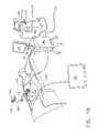
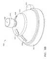
- FIG. 1Bis an illustration of the tissue treatment system.
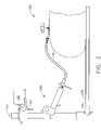
- FIG. 2is a view of the first aspect of the invention illustrating a fixation device.
- FIG. 3Ais a cross section of a first embodiment of a first aspect of the invention illustrating the surgical device guide
- FIG. 3Bis an exploded view of a first embodiment of a first aspect of the invention.
- FIG. 4Ais a cross section of a second embodiment of a first aspect of the invention.
- FIG. 4Bis an exploded view of a second embodiment of a first aspect of the invention.
- FIG. 5is a perspective view of a first aspect of the invention depicting the stem assembly rotated to expose the skin of the patient;
- FIG. 6Ais a perspective view of a first embodiment of a first aspect of the invention depicting the positioner in an unlocked position
- FIG. 6Bis a perspective view of a first embodiment of a first aspect of the invention depicting the positioner in a locked position;
- FIG. 6Cis a perspective view a first aspect of the invention depicting the depth stop assembly
- FIG. 6Dis an exploded view of a first aspect of the invention depicting an alternative embodiment of the depth stop assembly
- FIG. 6Eis a perspective view of a first aspect of the invention depicting an alternative embodiment of the depth stop assembly
- FIG. 7Ais a perspective view of a first aspect of the invention depicting an inserted ablation probe
- FIG. 7Bis a cross section of a first aspect of the invention depicting an inserted ablation probe at the reference position
- FIG. 7Cis a perspective view of a first aspect of the invention depicting the depth stop in the raised position
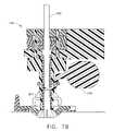
- FIG. 7Dis a cross section of a first aspect of the invention depicting the depth stop in the raised position
- FIG. 8Ais a cross section of a third embodiment of the first aspect of the invention.
- FIG. 8Bis an exploded view of a third embodiment of a first aspect of the invention.
- FIG. 9Ais a cross section of a fourth embodiment of the first aspect of the invention.
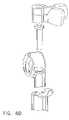
- FIG. 9Bis perspective view of the fourth embodiment of the first aspect of the invention.
- FIGS. 10A and 10Bare a procedure flow diagram of a second aspect of the invention.
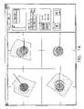
- FIG. 11is an illustration of the acquisition display screen in accordance with the second aspect of the invention.
- FIG. 12is an illustration of a display screen indicating the surgeon selected tumor outline in accordance with the second aspect of the invention.
- FIG. 13is an illustration of a display screen indicating target treatment volumes in accordance with the second aspect of the invention.
- FIG. 14is an illustration of a display screen indicating surgical device guide trajectory in accordance with the second aspect of the invention.
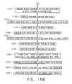
- FIGS. 15A and 15Bare a procedure flow diagram of a third aspect of the invention.
- the inventionrelates to the treating tissue in a patient.
- this descriptionwill discuss RF ablation of tissue targets using an RF ablation probe guided by ultrasound imaging.
- This embodimentis merely exemplary in nature and is in no way intended to limit the invention, its application, or uses.
- FIGS. 1A , 1 B, and 2depict an embodiment of the system components to be used in conjunction with a patient 170 that has been prepared for a laparoscopic procedure.
- Laparoscopic procedure setupis well known in the prior art.
- An ultrasound probe bracket 125 with ultrasound probe sensor 120attaches to a laparoscopic ultrasound probe 110 .
- the present embodimentutilizes an ultrasound imaging system 100
- the inventionis not limited to ultrasound devices and encompasses alternative imaging methodologies including, but not limited to, X-ray, computerized tomography (CT), positive electron emission (PET) or magnetic resonance imaging (MRI).
- the present embodimentutilizes an RF ablation probe 180
- the inventionencompasses the use of additional surgical devices such as a cryogen ablation probe, a microwave ablation probe, an ultrasound ablation probe, an ultrasound transducer, a heated element, and the like.
- the ultrasound system 100generates image data that is transmitted to a control device 140 .
- the ultrasound probe sensor 120provides position and orientation information to the control device 140 to assist in the “stacking” of the 2D ultrasound images to form a simulated 3D volume.
- the control device 140contains navigation circuitry and software to process the ultrasound 2D images generated by ultrasound probe 110 to form the simulated 3D image and the location information provided by the ultrasound probe sensor 120 .
- the control device 140may consist of a singular device or as multiple devices working together. One skilled in the art will appreciate that the functions of the control device 140 may be broken down over several components.
- a display screen 160 , keyboard 161 and mouse 162may be connected to the control device 140 . Alternative embodiments may use other input devices such as track balls, touch screens, styluses or the like.
- the control device 140is mounted on a mobile cart 210 which supports keyboard 161 and mouse 162 input devices as well as the display screen 160 . Images generated by the system are displayed on the display screen 160 .
- the positioner 150is a surgical device guide and includes a positioner sensor 155 which is also connected to the control device 140 .
- the patient 170lies on an operating table 200 and the positioner 150 is placed in contact with the patient 170 .
- the ablation probe 180is inserted into the patient 170 through the positioner 150 .
- the positioner 150is given additional stability by a fixation device 190 that attaches to an operating room table rail 195 .
- the fixation device 190 depicted in FIG. 2is available in the Bookwalter Endoscopic Instrument Kit commercially available from Codman, Inc. of Raynham, Mass. Alternative embodiments may include other fixation devices or adhesives to stabilize the location of the positioner 150 with respect to the patient 170 .
- the fixation device 190has a rigid arm 191 that supports a transmitter 192 .
- the transmitter 192may be attached to the wall or ceiling of the room, or any other fixed location.
- the signal from the transmitter 192is picked up by both the ultrasound probe sensor 120 and positioner sensor 155 and serves as a reference point for the system.
- the fixation devicemay also include a fixed calibration point 193 used to calibrate the positioner 150 .
- orientation and position of the positioner 150 and the ultrasound probe 110are determined based upon magnetic field sensors, such as the sensors described in U.S. Pat. No. 4,945,305 to Blood, the disclosure of which is incorporated herein by reference.
- the systemincludes a magnetic transmitter 192 mounted on the fixation device 190 , a magnetic positioner sensor 155 attached to the positioner 150 , and a magnetic ultrasound probe sensor 120 attached to the ultrasound probe 110 .
- the control device 140is capable of performing the calculations necessary to determine the location of the positioner 150 with respect to the images generated by the ultrasound probe 110 .
- There are several possible methods of determining the position and orientation of the positioner 150 and ultrasound probe 110An alternative embodiment utilizes optical sensors attached to the positioner 150 and ultrasound probe 110 to detect their position and orientation.
- a laparoscopic camera 115may be present and connected to the control device 140 to enable side-by-side viewing of the camera 115 with other displays generated by the control device 140 . Alternatively, the laparoscopic camera may be connected to an independent operating room monitor 116 .
- the positioner 150consists of a stem assembly 300 and a depth stop assembly 320 .
- an outer stem 310that includes a semispherical portion 331 .
- Semisphericalas used herein, means having the shape of a portion of a sphere.
- the semispherical portion 331has a stem radius 330 with slots 311 that enable the stem radius 330 to nestle into a corresponding frame radius 341 of frame 340 .
- the stem radius 330 and the frame radius 341function similarly to a ball joint, allowing the outer stem 310 to rotate with respect to the frame 340 .
- the outer stem 310may be connected to the frame 340 by a ball joint.
- An inner stem 315 including a stem flare feature 322 that mates with the inside surface of the semispherical portion of the outer stem 331is positioned within the outer stem 310 .
- the inner stem 315has a channel 800 into which a needle-like surgical device, such as an RF ablation probe, a biopsy needle or the like may be inserted.
- the surgical devicemay be inserted into the positioner 150 through the entry point 371 , pass through the channel 800 and exit the positioner 150 at the exit point 372 .
- the channel 800may be cylindrical in shape. Alternatively, the channel 800 may be multi-sided or triangular such that the sides of the channel 800 securely grip the surgical device.
- the proximal end of the inner stem 315includes notches 318 that enable the stem head 319 to snap into a recess 470 in knob 380 .
- the knob 380has a ramp surface 326 that engages the outer stem ramp surface 323 . Grasping the knob 380 and rotating it to one side draws the inner stem 315 through the outer stem and, consequently, draws the semispherical portion 331 of the outer stem into the mating frame radius 341 .
- the slots 311allows the stem radius 330 to expand and reactive forces fix the angular position of the outer stem 310 in the chosen orientation, locking the trajectory of any inserted surgical device. Trajectory, as used herein, refers to the path of the surgical device into the body of the patient.
- the frame 340is attached to a holder 325 by a hinged joint.
- the frame 340includes a hinge pin 342 feature that mates with a hinge recess 343 of the holder 325 .
- a snap lever 391engages a snap catch 392 to secure the frame 340 within the holder 325 . Disengaging the snap lever 391 and the snap catch 392 allows the frame 340 to be rotated out of the holder 325 , permitting the surgeon to access the skin of the patient 170 .
- the holder 325has a bottom surface 327 that bears against the skin of the patient 170 .
- the center of the stem radius 330is located on or marginally below the bottom surface 327 , putting the center of stem radius 330 in contact with patient 170 .
- the center of angular rotation of the stem radius 330is at or near the skin of the patient 170 without significant skin deformation, due to the semispherical shape of the stem radius 330 . Placing the center of rotation at or near the surface of the skin maximizes the range of angular motion through the incision in the skin and minimizes the size of the incision required.
- the holder 325has a clip end 303 which may be attached to the mating receptacle 304 of a fixation device 190 .
- the holder 325may also utilize a flexible stabilizer 350 to fix the position of the holder 325 with respect to the patient 170 .
- a flexible stabilizer 350has a ring adhesive 316 that enables it to attach to the flat area 327 of the holder 325 and a patient adhesive 317 which attaches to the patient 170 .
- the patient adhesive 317is covered by a peelable cover 355 to prevent the flexible stabilizer 350 from adhering prior to final placement of the positioner 150 on the patient 170 .
- the depth stop assembly 320is seated on top of the knob 380 and is attached to the outer stem 310 by deflection fingers 360 .
- the depth stop assembly 320consists of a sensor frame 385 , an end disc 370 , two button catches 390 , and their respective elastic bands 395 .
- the shelves 365 of the deflection fingersengage a lip 366 of the end disc 370 .
- the depth stop 320utilizes a positioner sensor 155 embedded in the sensor frame 385 to communicate the positioner 150 location and orientation to the control device 140 .
- the sensor frame 385houses the button catches 390 and their respective elastic bands 395 . Squeezing the button catches 390 bends the deflection fingers 360 and releases the depth stop assembly 320 from the outer stem 310 .
- the end disc 370covers the depth stop assembly 320 and is fixed in place.
- a movable shutter 345is attached to the outer stem 310 and prevents surgical devices from passing through the channel 800 of the positioner 150 .
- the shutter 345incorporates a shutter stop 307 , which passes through the window access port 306 and projects into the channel 800 .
- the shutter 345is held in place by an elastic ring 305 , which allows the shutter 345 to pivot. Surgical devices inserted in the positioner 150 rest upon the shutter stop 307 at a known, fixed reference position.
- the shutter 345is pulled, but not removed, from the window access port 306 to remove the shutter stop 307 from the channel 800 and allow surgical devices to pass through the positioner 150 .
- the shutter 345may be attached to the outer stem 310 by a hinged joint biased by a spring. Pressure on the shutter 345 causes it to pivot and removes the shutter stop 307 from the channel 800 .
- An insert 335may be placed in the channel 800 to accommodate surgical devices of different diameters.
- the positioner 150 ′includes a positioner sensor 155 ′ housed in the outer stem 310 ′, held in place with potted epoxy 314 ′ and connected to a control device 140 ′.
- This alternative embodimentdoes not include a depth stop assembly 320 or a shutter 345 as described in the previous embodiment.
- the proximal end of the inner stem 315 ′has notches 318 ′ that enable the stem head 319 ′ to snap into a recess 470 ′ of knob 380 ′.
- a cap 460 ′inserts into stem head 319 ′ to keep it securely in place.
- An insert 335 ′may be placed in the channel 800 ′ to accommodate surgical devices of different diameters.
- the knob 380 ′has a ramp surface 326 ′ that engages an outer stem ramp surface 323 ′. Grasping the knob 380 ′ and rotating it to one side draws the inner stem 315 ′ through the outer stem and, consequently, draws a semispherical portion 331 ′ of the outer stem into a mating frame radius 341 ′ of a frame 340 ′. Slots 311 ′ allows the stem radius 330 ′ of a stem flare feature 322 ′ of the outer stem 310 ′ to expand and reactive forces fix the angular position of the outer stem 310 ′ in the chosen orientation, locking the trajectory of any inserted surgical device.
- the frame 340 ′is attached to a holder 325 ′ by hinge pin 342 ′ feature that mates with a hinge recess 343 ′ of a holder 325 ′.
- a snap lever 391 ′engages a snap catch 392 ′ to secure the frame 340 ′ within the holder 325 ′.
- the holder 325 ′has a clip end 303 ′ which may be attached to the mating receptacle 304 ′ of a fixation device 190 ′ to hold the positioner 150 ′ in place.
- the holder 325 ′may also utilize a flexible stabilizer 350 ′ to fix the position of the holder 325 ′ with respect to the patient 170 ′.
- the flexible stabilizer 350 ′has a ring adhesive 316 ′ that enables it to attach to a flat area 327 ′ on the holder 325 ′ and a patient adhesive 317 ′ which attaches to the patient 170 ′.
- the patient adhesive 317 ′is covered by a peelable cover 355 ′ to prevent the flexible stabilizer 350 ′ from adhering prior to final placement of the positioner 150 ′ on the patient 170 ′.
- the stem assembly 300 of the positionermay be rotated to expose the patient's skin by disengaging snap lever 391 from snap catch 392 .
- Four slots 410 within the holder 325act as skin nick guides, enabling a scalpel to create a transdermal incision between the slots for easy insertion of the surgical device through the skin.
- Re-engaging the snap lever 391 and snap catch 392returns the outer stem 310 to its fixed position within the positioner 150 .
- the stem assembly 300may be connected to the holder 325 using multiple snap catches rather than a hinged joint, so that the stem assembly 300 may be removed from the holder 325 to expose the skin.
- a lancemay be inserted through the channel 800 to nick the skin without removing the stem assembly 300 from the holder 325 .
- the depth stop assembly 320includes button catches 390 which allow the depth stop assembly 320 to be removed from the outer stem 310 .
- the knob 380covers one of the button catches 390 preventing the depth stop 320 from being removed from the outer stem 310 .
- Rotating the knob 380 to the locked positionexposes the second button catch 390 .
- Squeezing the button catches 390aligns the through holes 397 and allows the depth stop assembly 320 to be removed from the outer stem 310 .
- the button catchesare biased by elastic bands 395 attached to posts 430 of the sensor frame 385 . Squeezing the button catches 390 stretches the elastic bands 395 and aligns the through holes 397 .
- An alternative embodiment of the depth stop 320 construction using a clamp without a positioner sensor 155is depicted in FIGS. 6D and 6E .
- FIGS. 7A , 7 B, 7 C and 7 Dwhen the button catches 390 are squeezed the through holes 397 align.
- An ablation probe 180may be inserted into the channel 800 through the through holes 397 until it rests against the shutter stop 307 at a known, fixed, reference position. Squeezing the button catches 390 moves the deflection fingers, allowing the depth stop 320 to be removed from the outer stem 310 and positioned on the ablation probe 180 .
- the through holes 397become misaligned and grip the ablation probe 180 .
- the through holes 397act as a clamp, fixing the position of the depth stop 320 on the ablation probe 180 .
- a third embodiment of a first aspect of the inventionincludes a sliding disk 310 ′′ which allows the surgeon to adjust the insertion point after the holder 325 has adhered to the patient.
- insertion pointis the point on the skin of the patient where the ablation probe is inserted.
- the stem assembly 200 ′′has a single stem 210 ′′ with a semispherical portion 231 ′′ at its distal end.
- the semispherical portion 231 ′′has a stem radius 230 ′′ that nestles into a corresponding frame radius 241 ′′ of a frame 240 ′′ and a bottom surface that bears against patient 250 ′′.
- the stem radius 230 ′′ and the frame radius 241 ′′function similarly to a ball joint, allowing the stem 210 ′′ to rotate with respect to the frame 240 ′′. Therefore, the center of angular rotation of the stem radius 230 ′′ is at or near the skin of the patient 250 ′′ without significant skin deformation, maximizing the range of motion through a small incision in the skin of the patient 250 ′′.
- a locking knob 220 ′′is attached to the stem 210 ′′ by a threaded surface.
- the locking knob 220 ′′has a locking knob radius 233 ′′ that bears on the disk feature 245 ′′.
- the disk feature 245 ′′bears on the frame 240 ′′.
- the axis 260 ′′ of stem 210 ′′determines the trajectory of positioner 150 ′′. Grasping the knob 215 ′′ and moving it in one direction will cause stem 210 ′′ to pivot about the center of stem radius 230 ′′, changing the trajectory of the positioner 150 ′ and any inserted surgical device.
- the bottom surface on semispherical portion 231 ′′will rock gently on the skin of patient 250 ′′, allowing the center of stem radius 230 ′′ to maintain contact with the patient.
- the stem radius 230 ′′will slide against the abutting corresponding radius on frame 240 ′′. Additionally, the locking knob radius 233 ′′ will slide against the adjacent radius on the disc feature 245 ′′, moving disk feature 245 within the slot in frame 240 ′′.
- the locking knob 220 ′′may be used to lock stem 210 ′′ into a fixed position after the trajectory is planned. Rotating locking knob 220 ′′ in one direction will force the locking knob radius 233 ′′ against its mating radius in the disk feature 245 ′′ and will pull semispherical portion 231 ′′ against frame 240 ′′ at the point where radius stem 230 ′′ abuts frame 240 ′′. The reactive forces will lock the stem 210 ′′ into the chosen position.
- the sliding disk 310 ′′allows the insertion point of the surgical device to be adjusted after the base 320 ′′ is fixed in position.
- Frame 240 ′′is attached to the platform 300 ′′ by a hinge joint.
- the platform 300 ′has a sliding disk 310 ′ that sits upon holder 320 ′′.
- the insertion pointmay be shifted by moving the sliding disk 310 ′′ upon the holder 320 ′′.
- a ring 330 ′′includes threaded surface 335 ′′ that interfaces with threaded surface 225 ′′ of the holder 320 ′′. Rotating the ring 330 ′′ in one direction will force the edge of the ring 330 ′′ against the sliding disk 310 ′′.
- the frictional forces from the ring 330 ′′ and the holder 320 ′′will fix the position of the sliding disk 310 ′′.
- the positioner sensor 175 ′′is embedded into the knob portion 215 ′′ of stem 210 ′′.
- the positioner sensor 175 ′′ wiresenter stem slot 207 a ′′, traverse the inner slot 206 ′′ and exit at stem slot 207 b ′′.
- the wires of positioner sensor 175 ′′then pass through the frame 240 ′′ and terminate on an edge card 208 ′′.
- a positioner transmitter 178 ′′is embedded in the clamp arm 260 ′′ which will be attached to the frame 240 ′′.
- the wires of positioner transmitter 178 ′′are encased within cable 265 ′′.
- the clamp arm 260 ′′includes an embedded edge card 280 ′′ in one of the flex members 290 ′′ that mates with the edge card 208 ′′ in the frame 240 ′′. Wires from the edge card 208 ′′ in the frame 240 ′′ connect with the wires of the edge card 280 ′′ embedded in the clamp arm 260 ′′. The tips 295 ′′ of the flex members 290 ′′ snap into grooves 297 ′′ of the frame 240 ′′. A tab 296 ′′ of the clamp arm 260 ′′ catches the recess 298 ′′ in platform 300 ′′ to hold the clamp arm 260 ′′ in place.
- the positioner 150 ′′includes a skin nick guide 330 ′′ which assists the surgeon in making a transdermal incision aligned with the center of the stem assembly 200 ′′.
- the platform 300 ′′includes a stem hinge 315 ′′ that allows the stem assembly 200 ′′ to be rotated out of the center of the platform 300 ′′.
- the platform 300 ′′includes a skin nick guide hinge 321 ′′ that enables the skin nick guide 360 ′′ to rotate into the center of the platform 300 ′′, such that the slot in the skin nick guide 330 ′′ is aligned with the center of the aperture in the platform 300 ′′. When not in use, the skin nick guide 330 ′′ is rotated out of the platform 300 ′′.
- the holder 320 ′′includes an adhesive 340 ′′ to attach the positioner 150 ′′ to the patient 120 ′′.
- the adhesive 340 ′′has a peelable cover 350 ′′ to prevent the adhesive 340 ′′ from adhering prior to final placement of the positioner 150 ′′.
- An insert 190 ′′may be placed in the stem 210 ′′ to accommodate surgical devices of different diameters.
- positioner 900utilizes domed structure to facilitate changes in the trajectory of the surgical device.
- the positioner 900includes a stem 902 with a stem flare feature 904 at its distal end.
- the stem flare feature 904nestles into a corresponding frame radius 905 of a frame 908 and functions similarly to a ball joint.
- the stem 902has a channel 926 for insertion of a surgical device.
- the stem 902includes a sensor arm 906 which houses the positioner sensor (not shown).
- the frame 908is seated within the holder 910 and attached to the lower dome 912 .
- the lower dome 912has fingers 914 which engage the lip 916 of the holder 910 to attach the lower dome 912 to the holder 910 .
- the snap catch 918is pivotally mounted on the holder 910 . Depressing the snap catch 918 releases one of the fingers 914 of the lower dome 912 and allows the lower dome 912 to be removed from the holder 910 . Removal of the lower dome 912 from the holder 910 , also removes the frame 908 from the holder 910 and allows the surgeon to access the skin of the patient even after the holder 910 is fixed in place.
- the holder 910may be secured to the patient using a flexible stabilizer (not shown) or, in an alternative embodiment, the holder 910 may include a clip end capable of being attached to a fixation device.
- An upper dome 920rests on the lower dome 912 . Wires from the positioner sensor (not shown) seated in the sensor arm 906 may pass through a slot 928 in the upper dome 920 to connect the positioner sensor to the control device.
- the stem 902passes through a collar 922 within the upper dome 920 .
- a knob 924 including a threaded surfaceengages a threaded surface on the stem 902 .
- the knob 924includes the channel 926 into which a surgical device may be inserted
- the configuration of the upper dome 920 and lower dome 912allows the surgeon to manipulate the trajectory of the positioner 900 .
- the upper dome 920slides over the surface of the lower dome 912 , allowing the stem 902 to rotate.
- the surgeonmay change the angle of insertion by grasping and moving the knob 924 , thereby changing the angle of the stem 902 and the channel 926 into which the surgical device will be inserted.
- the angle of insertionis limited by contact between the collar 922 surrounding the stem 902 and the top edge of the lower dome 912 .
- a slot 930 in the lower dome 912 and a matching frame slot 934 in the frame radius 905increase the range of the angle of insertion and therefore the trajectory.
- the collar 922may be inserted in the slot 930 to increase the angle of insertion.
- the stem 902is inserted into the matching frame slot 934 in the frame radius 905 .
- An arrow 932 on the upper dome 920indicates when the upper dome 920 is aligned such that the collar 922 may be inserted into the slot 930 in the lower dome 912 without interference due to the sensor arm 906 .
- the lower dome 912may be rotated three hundred and sixty degrees within the holder 910 , thereby allowing the surgeon to reposition the slot 930 and the frame slot 934 as needed.
- the surgeonmay lock the trajectory of the positioner 900 .
- the trajectorymay be locked by grasping and turning the knob 924 .
- Rotating the knob 924 in one directionwill draw the stem 902 up through the collar 922 , drawing the stem flare feature 904 of the stem 902 into the mating frame radius 905 .
- the bottom of the knob 924will press down on the collar 922 .
- Reactive forcesfix the angular position of the stem 902 in the chosen orientation, locking the trajectory of a surgical device inserted in the channel 926 .
- the depth stop assembly 320may be used independently from the remainder of the positioner 150 .
- the depth stop 320may be used with any surgical device of a fixed geometry to control insertion of the surgical device within a patient 170 .
- the depth stop assemblyincluding the positioner sensor 155 , is associated with an insertion point.
- the depth stop assemblyis positioned on a surgical device that has a known, fixed geometry.
- the tip of the surgical devicemust be located at a known reference point relative to the depth stop assembly.
- the control device 140is able to calculate the position of the tip of the surgical device upon insertion into the patient 170 .
- the depth stopis illustrated in conjunction with a needle-like surgical device.
- the depth stop assemblymay be used with any surgical device of a fixed geometry, if the geometry is known and input into the control device 140 .
- a second aspect of the inventionrelates to a method for treating tumors or lesions in a patient.
- One embodiment of the methodbegins with setting up the equipment at step 500 .
- the procedure set-up for a laparoscopic procedureis well established and documented in independent surgical references. Any manufacturers' ablation probe may be used in this embodiment.
- the ablation probe 180is utilized as presented in the manufacturer's product literature. The method is not limited to the use of ablation probes and may apply to the guidance of any surgical device.
- the mobile cart 210 containing the keyboard 161 , mouse 162 , and display screen 160is present and connected to the control device 140 .
- the ultrasound probe bracket 125 with the ultrasound probe sensor 120is mounted on the ultrasound probe 110 .
- the ultrasound system 100 and positioner sensor 155are also connected to the control device 140 .
- the laparoscopic camera 115is connected to an independently operating room monitor 116 .
- a fixation device 190is mounted to the operating room table bed rail 195 , such that the free, distal end of the fixation device is located proximate to the insertion point in a light friction state.
- the fixation device 190has a second rigid arm 191 that supports a transmitter 192 .
- the transmitter 192serves as a reference point during the method and is connected to the control device 140 .
- the positioner 150is attached to the free end of the fixation device 190 .
- the surgeonpasses the laparoscopic camera 115 and ultrasound probe 110 through their respective trocars to the tissue site.
- the surgeoncalibrates the ultrasound probe 110 and the positioner 150 .
- the location of the ultrasound probe sensor 120 on the ultrasound probe 110is known by the control device 140 .
- the surgeonmay enter information regarding the physical location of the ultrasound probe sensor 120 using the keyboard 161 and mouse 162 .
- the control device 140the location of the positioner sensor 155 on the positioner 150 is known.
- the surgeonmay enter information regarding the physical location of the positioner sensor 155 .
- the locations of the entry point 371 and exit point 372 , and therefore the location and orientation of the channel 800 , relative to the positioner sensor 155may be calculated by the control device 140 .
- the surgeonTo calculate the locations of the entry point 371 and exit point 372 , the surgeon must first place the entry point 371 at a fixed location, such as the calibration point 193 (shown in FIG. 2 ). The surgeon must then pivot the positioner 150 about the entry point 371 , holding the entry point 371 at the calibration point 193 . During the pivot motion, the positioner sensor 155 transcribes a portion of a sphere centered at the entry point 371 . By calculating the center of the sphere transcribed by the positioner sensor 155 , the control device 140 is able to determine the relationship between the positioner sensor 155 and the entry point 371 .
- the control device 140is able to determine the location of the exit point 372 relative to the positioner sensor 155 . Based upon the locations of the entry point 371 and exit point 372 , the control device 140 is able to calculate the trajectory of a surgical device inserted in the channel 800 of the positioner 150 .
- the surgeonmay also calibrate the ultrasound imaging system at step 530 .
- the control device 140may utilize the output data generated by existing ultrasound imaging systems.
- the control device 140may use the output data transmitted by the ultrasound imaging system to the display screen 160 .
- This datamay include not only the ultrasound 2D representation of a portion of the body volume, but also additional information such as the patient name.
- the surgeon or technicianmay identify the portion of the display screen 160 containing the 2D representation of the body volume. Once this portion of the display screen is identified, the control device 140 is able to determine the relationship between the 2D representation of the body volume and the position of the ultrasound probe sensor 120 to determine the position of that 2D representation of the body volume relative to the transmitter 192 which serves as the reference point.
- the control device 140initiates in ultrasound acquisition mode and the ultrasound probe 110 is used to capture the desired tissue image.
- the surgeonmay use an ultrasound probe 110 to generate a 2D representation of a portion of the body volume.
- the surgeonmay generate a data set consisting of a series of 2D representations of the body volume.
- the control device 140uses location information received from the ultrasound probe sensor 120 while the ultrasound probe 110 generates the 2D representations, the control device 140 “stacks” the 2D representations to create a 3D image or model of a portion of the body volume.
- the surgeonIn acquisition mode, the surgeon is able to view the 3D image on the display screen 160 to ensure that the tumor tissue is clearly visible in the 3D image.
- the control device 140may create three orthogonal views and an oblique simulated 3D view of the image on the display screen 160 , as illustrated in FIG. 11 .
- the surgeonis able to generate several data sets of images and select the best data set from which to generate a treatment plan.
- the surgeonscrolls through the 3D image manipulating the views to identify the outline of the tumor using the control device 140 .
- the surgeonis able to identify the outline of the tumor using a variety of methods, including freehand drawing using a mouse, a stylus or a light pen. Additionally, the surgeon may be able to select a circle of interest in any of the orthogonal views. By selecting circular areas in each of the orthogonal views, the surgeon may effectively outline the tissue volume. Software methods for drawing circles are well established in the prior art.
- the surgeonmay define a circle by using a mouse to select two points on an orthogonal view. The first point defines the center of the circle.
- each of the three circles selected in step 550defines a cylinder or column of data within the 3D image.
- the control device 140analyzes the intersection of the three cylinders to define the tumor volume.
- the surgeonmay also utilize additional drawing tools such as a cutting plane to define the outline of the tumor volume. By selecting two points on any one of the orthogonal views to form a line, the surgeon may define a cutting plane. By selecting a third point on one side of the plane, the surgeon may cut away or eliminate all of the data on that side of the cutting plane.
- Alternative embodimentsmay include utilizing additional geometric shapes and methods for defining such shapes.
- One skilled in the artwill appreciate that there are numerous methods for defining volumes.
- the control device 140uses the outline to process the tumor volume in step 560 .
- the control device 140may remove all data outside of the tumor outline from the display screen 160 , as illustrated in the simulated 3D view shown in FIG. 12 .
- the control device 140may also analyze the data within the tumor outline identified by the surgeon. Generally, the density of tumor tissues varies from that of normal tissue. By comparing relative tissue density, as represented by pixel intensity, the control device 140 is able to identify tumor tissue and further refine the tumor outline.
- the surgeonmay identify a point on the display screen 160 as being part of the tumor.
- the control device 140may compare the tissue density of the point selected by the surgeon to the density of the surrounding tissue. By determining the areas in the image where the tissue density changes, the control device 140 may identify the tumor volume. The control device 140 may then highlight the perimeter of the tumor volume in each of the views presented on the display screen 160 . In step 570 , the tumor volume is presented on display screen 160 as a 3D rendered view which can be manipulated and measured.
- the surgeonmay apply a margin offset to expand the tumor volume for ablation planning in step 580 . Based on this expanded volume, the surgeon may select an appropriate ablation probe 180 and inputs the selected probe's ablation parameters, such as length, ablation diameter and ablation diameter offset from the physical probe tip. The parameters may be entered into the control device 140 using the keyboard 161 and the mouse 162 .
- a treatment volumeis the volume of tissue that is affected by the ablation probe 180 when the ablation probe 180 is held stationary and energized.
- a target treatment volumeis a volume of tissue that is to be ablated or treated with the ablation probe.
- planning modethe surgeon may place target treatment volumes onto the tumor volume based on the ablation parameters of the ablation probe 180 until the desired coverage or “mapping scheme” is achieved. The surgeon may select the position of target treatment volumes using an input device such as a mouse 162 to direct a cursor on the display screen 160 .
- a numbered reference table on the display screen 160lists the target treatment volumes in the order in which they are to be treated. By manipulating the reference table, the surgeon may alter the treatment order or delete target treatment volumes.
- Software in the control device 140enables assessment of the tumor volume coverage.
- the control device 140indicates any portions of the tumor volume not incorporated in any of the target treatment volumes.
- the control device 140may automatically calculate the target treatment volumes and generate a mapping scheme.
- the control device 140dynamically displays the individual target treatment volume locations on the orthogonal and 3D views.
- the treatment volumesmay be color-coded to allow the surgeon to distinguish between the selected treatment volume, target treatment volumes that have already been treated and target treatment volumes that are yet to be treated.
- step 610after the mapping scheme is defined, the control device 140 is updated to treatment mode.
- treatment modethe selected treatment volume, which is the next target treatment volume to be treated, is highlighted and the positioner trajectory is indicated on the display screen 160 .
- the trajectoryis an imaginary straight ray emanating from the positioner 150 indicating the projected path of the ablation probe 180 in the patient.
- the trajectory lineis updated on the display screen as the positioner 150 is moved.
- the control device 140is able to calculate the positioner trajectory 150 based upon the position and orientation of the positioner sensor 155 relative to the transmitter 192 , which serves as the reference point.
- the positioner sensor 155is in a fixed relation to the channel 800 into which the ablation probe 180 will be inserted.
- the 3D image of the body volumewas generated by the control device 140 using the transmitter 192 as a reference point. This common reference point allows the control device 140 to project the trajectory of the positioner 150 onto the orthogonal and simulated and 3D views on the display screen 160 .
- the surgeonmay select the insertion point for the ablation probe 180 .
- the positioner 150may be moved over the skin surface and angle of the outer stem 310 may be adjusted until the positioner trajectory and insertion point are in the desired location.
- the peelable cover 355is removed from the flexible stabilizer 350 and the positioner 150 is pressed lightly against the patient 170 .
- the patient adhesive 317 on the flexible stabilizerwill cause the positioner 150 to adhere to the patient 170 .
- the fixation device 190may also be locked into position.
- the positioner 150may be held in place solely by a fixation device 190 , or by the flexible stabilizer 350 .
- the transmitter 178 ′′may be contained within a clamp arm 260 ′′.
- the clamp arm 260 ′′must be held stationary during selection of the insertion point to provide a constant reference point.
- the clamp arm 260 ′′may be attached to the frame 240 ′′ of the positioner 150 ′′ where it will remain in a fixed location. At this point a new 3D image must be generated using the new reference point.
- step 620the frame 340 is unlatched as the snap lever 391 is disengaged from snap catch 392 .
- the frame 340is rotated to expose slots 410 within the holder 325 .
- the slots 410enable a surgeon to create a transdermal incision to permit easy insertion of the ablation probe 180 .
- the frame 340is rotated back into place and the snap lever 391 re-engages the snap catch 392 to secure the frame 340 .
- a lancemay be inserted through the channel 800 to create a transdermal incision.
- the positioner 150 trajectoryis aligned with the selected treatment volume by rotating the outer stem 310 and utilizing the trajectory indicator shown on the display screen 160 .
- the display screen 160will indicate when the trajectory of the positioner 180 is aligned with the selected treatment volume.
- the positioner 150may be locked into position by turning the knob 380 .
- Turning the knob 380exposes the second depth stop button catch 390 , as shown in FIGS. 6A and 6B .
- the display screen 160indicates the distance from the placement of the positioner 150 on the skin to the target point for the selected treatment volume.
- Target pointis the point where the tip of the ablation probe must be located to ablate a target treatment volume.
- the display screen 160may indicate the target points for each of the target treatment volumes. The display screen 160 may also indicate when the positioner trajectory is aligned with the target point of the selected treatment volume.
- step 640depth stop buttons 390 are squeezed, aligning the through holes 397 and allowing the insertion of the ablation probe 180 into channel 800 .
- the ablation probe 180is inserted in the positioner 150 until the distal tip of the ablation probe 180 contacts the shutter stop 307 , as shown in FIGS. 7A and 7B .
- the positioner sensor 155is in a fixed relation to the channel 800 in which the ablation probe 180 is seated, such that the control device 140 is able to calculate the position and orientation of the inserted ablation probe 180 based upon the position and orientation of the positioner sensor 155 .
- the surgeonmay position the depth stop on the ablation probe 180 such that the depth stop limits the insertion of the ablation probe 180 in to the patient to the distance from the insertion point to the target point.
- the surgeonmay select raise depth stop mode using the keyboard 161 or mouse 162 .
- raise depth stop modethe display screen 160 provides a readout based upon depth stop position. The readout decreases to zero as the depth stop 320 is raised along the ablation probe shaft until the height of the depth stop on the ablation probe shaft equals the depth the ablation probe must be inserted to treat the selected treatment volume. This dimension incorporates an adjustment for any offset of the effective ablation volume from the physical end of the ablation probe, as entered by the surgeon at step 580 .
- FIG. 7Cdepicts a depth stop 320 raised along the ablation probe shaft. Once the depth stop 320 is raised to the appropriate height, releasing the depth stop buttons 390 will cause the through holes 397 to become misaligned. The walls of the through holes 397 will then grip the ablation probe 180 like a clamp, holding the depth stop 320 in place.
- FIG. 7Ddepicts the ablation probe 180 inserted in the positioner, in contact with the shutter stop 307 and the depth stop 320 raised to a predetermined height.
- the positioner sensor 155communicates its new coordinates to the control device 140 based on its location relative to the transmitter 192 .
- the surgeonmay then select insert depth stop mode, such that the display screen 160 indicates the depth to which the ablation probe must be inserted to treat the selected treatment volume.
- the surgeoninserts the ablation probe 180 into the patient 170 until the depth stop 320 returns to its reengaged location on the positioner 150 and the display screen 160 depth readout is equal to zero.
- the surgeonenergizes the ablation probe 180 to treat the target volume.
- the surgeonmay select the selected treatment volume using the mouse 162 to indicate the treatment of the selected treatment volume is complete.
- step 680if there are any un-ablated target treatment volumes, the control device 140 advances to the next numbered target treatment volume.
- the display screen 160highlights the next selected treatment volume and grays the completed target treatment volume in the onscreen images and in the reference table listing of target treatment volumes.
- step 690 of the processthe surgeon depresses the depth stop buttons 390 and removes the ablation probe 180 from the tissue. Turning the knob 380 unlocks the positioner trajectory.
- step 700the process returns to step 630 and repeats the trajectory and treatment until all the target treatment volumes are ablated. The surgeon has the option to re-scan the tumor tissue at any point. In one embodiment the control device 140 will indicate unablated tumor tissue on the display screen 160 .
- the control device 140allows the surgeon to store of any of the ultrasound images, orthogonal 2D or 3D views, or ablation plans.
- the informationmay be stored in a hard drive, a disk drive, a CD or any other storage medium known in the art.
- a screen capturemay be taken at any point during the method and printed at a later time. As used herein, a screen capture transfers the current image from the display screen 160 and saves it to a graphics file for later use.
- a third aspect of the present inventionrelates to a method for ablating tumors within a patient using the tumor as a fiducial.
- a fiducialis a reference point.
- the imaging systemis able to capture the motion of the tumor motion due to respiration.
- the systemmay create an image of the tumor at its longest dwell time.
- dwell timeis the brief pause between inhalation and exhalation at each end of the respiratory cycle.
- the dwell time imageis used to generate the ablation plan.
- the ultrasound probeis used to monitor the respiration cycle of the patient as the control device 140 synchronizes the motion of the tumor with the ablation plan image.
- the control device 140indicates to the surgeon when the moving tumor is aligned with the ablation plan image. In one embodiment the control device 140 will alert the surgeon slightly before the tumor is aligned with the ablation plan image to allow for the reaction time of the surgeon. By inserting the surgical device only when the tumor is aligned with the ablation plan image, this method removes error due to respiration motion.
- one embodiment of the third aspect of the inventionbegins at step 1000 with setting up the equipment.
- the procedure set-up for a laparoscopic procedureis well established and documented in independent surgical references.
- the mobile cart 210 containing the keyboard 161 , mouse 162 , and display screen 160is present and connected to the control device 140 .
- Ultrasound probe bracket 125 with ultrasound probe sensor 120is mounted on the ultrasound probe 110 .
- the ultrasound system 100 and the positioner sensor 155are connected to the control device 140 .
- the laparoscopic camera 115is connected to an independently operating room monitor 116 .
- a fixation device 190is mounted to the operating room table bed rail 195 such that the free, distal end is located proximate to the insertion point.
- the fixation device 190is in a light friction state to allow for further adjustments in position.
- the fixation device 190has a second rigid arm 191 that supports the transmitter 192 .
- the transmitter 192acts as a reference point and is connected to the control device 140 .
- the positioner 150is attached to the free end of the fixation device 190 .
- the surgeonpasses the laparoscopic camera 115 and ultrasound probe 110 through their respective trocars to the tissue site.
- step 1030the surgeon calibrates the ultrasound probe 110 and positioner 150 , as described in detail above.
- the control device 140initiates to the ultrasound acquisition mode and the ultrasound probe 110 is used to capture the desired tissue image.
- the ultrasound probe 110moves it generates a data set consisting of a series of 2D representations of the body volume. These 2D representations are stacked to create a 3D image of a portion of the body volume, as described in detail above with respect to the second aspect of the present invention.
- the control device 140creates three orthogonal 2D views and an oblique simulated 3D view on the display screen 160 .
- the surgeonIn acquisition mode the surgeon is able to view the simulated 3D view and the 2D views on the display screen 160 and ensure that the tumor tissue is completely covered by the image of the body volume. In one embodiment, the surgeon is able to generate several images and select the best image from which to create a treatment plan.
- the surgeonscrolls through the 3D image manipulating the views to identify the outline of the tumor using the control device 140 .
- the surgeonis able to identify the outline of the tumor using a variety of methods, including freehand drawing using a mouse, a stylus or a light pen. Additionally, the surgeon may be able to select a circle of interest in any of the orthogonal views. By selecting circular areas in each orthogonal view, the surgeon is effectively able to outline the tissue volume. Software methods for drawing circles are well established in the prior art.
- the surgeonmay define a circle by selecting two points on an orthogonal view. The first point defines the center of the circle.
- each of the three circles selected in step 1050defines a cylinder or column of data within the 3D image.
- the softwareanalyzes the intersection of those three cylinders to define the tumor volume.
- the surgeonmay also utilize additional drawing tools such as a cutting plane to define the outline of the tumor volume. By selecting two points on any one of the orthogonal views to form a line, the surgeon may define a cutting plane. By selecting a third point on one side of the plane, the surgeon may cut away or eliminate all of the data on that side of the cutting plane.
- Alternative embodimentsmay include utilizing additional geometric shapes and methods for defining such shapes.
- One skilled in the artwill appreciate that there are numerous methods for defining volumes. The present invention is not intended to be limited to a particular method.
- the surgeonidentifies a point on the tumor which serves as the fiducial or reference point.
- the control device 140uses the outline to process the tumor volume in step 1070 .
- the control device 140may remove all data outside of the tumor outline from the display screen 160 , as illustrated in the simulated 3D view shown in FIG. 12 .
- the control device 140may analyze the data within the outline identified by the surgeon. By comparing relative tissue density, as represented by pixel intensity, the control device 140 is able to further define the tumor volume within the outline.
- the surgeonmay identify a point on the display screen 160 as being part of the tumor.
- control device 140may automatically generate an outline of the tumor volume and highlight the tumor's perimeter in each of the views presented on the display screen 160 .
- the tumor volumeis presented on display screen 160 as a 3D rendered view that can be manipulated and measured.
- the surgeonmay apply a margin offset to expand the tumor volume for ablation planning in step 1080 . Based on this expanded volume, the surgeon may select an appropriate ablation probe 180 and input the selected probe's ablation parameters, such as length, ablation diameter and ablation diameter offset from the physical probe tip.
- the ablation parametersmay be entered into the control device 140 using a keyboard 161 and a mouse 162 .
- step 1090the surgeon holds the ultrasound probe 110 in a fixed position while collecting image data to capture a complete respiratory cycle of the patient 170 .
- the control device 140records the positional extremes, length of travel and dwell times at the ends of the respiratory cycle.
- the position of the tumor volume at the longest dwell timeis defined as the dwell position.
- the control device 140generates an image of the tumor in the dwell position, referred to herein as the dwell position image.
- the dwell position imageis depicted on the display screen 160 , allowing the surgeon to rotate, pass cutting planes, enlarge or otherwise manipulate the dwell position image.
- the control device 140is updated to the planning mode to generate a mapping scheme at step 1120 .
- the surgeonmay place target treatment volumes onto the tumor volume based on the ablation parameters of the ablation probe 180 , until the desired coverage or mapping scheme is achieved.
- the surgeonmay select the position of target treatment volumes on the display screen 160 using an input device such as a mouse 162 to direct a cursor on the display screen 160 .
- Software in the control device 140enables assessment of the tumor coverage.
- a numbered reference tablelists each of the selected target treatment volumes in the order in which they are to be treated. By manipulating the reference table, the surgeon may alter the treatment order or delete target treatment volumes.
- control device 140may automatically calculate target treatment volumes and generate a mapping scheme.
- the control device 140dynamically displays the individual target treatment volume locations on the orthogonal and 3D images. Once the surgeon is satisfied with the mapping scheme, the control device 140 is updated to treatment mode and the initial selected treatment volume is highlighted.
- the surgeonmoves the positioner 150 to the area of the incision.
- the display screen 160indicates the positioner 150 trajectory and the selected treatment volume. Using the projected trajectory, the surgeon may select the insertion point for the ablation probe 180 .
- the peelable cover 355is peeled off the flexible stabilizer 350 to expose the patient adhesive 317 .
- Positioner 150is returned to the skin surface and outer stem 310 angled until the trajectory alignment and insertion point are in the desired location.
- the flexible stabilizer 350is pressed lightly against the patient and the fixation device 190 is locked into position.
- the frame 340is unlatched as snap lever 391 is disengaged from snap catch 392 .
- the frame 340is rotated to expose slots 410 within holder 325 .
- the slots 410enable the surgeon to create a transdermal incision to permit easy insertion of the ablation probe 180 through the skin.
- the frame 340is rotated back into place and the snap lever 391 re-engages snap catch 392 .
- a lancemay be inserted through the channel 800 to create the transdermal incision, eliminating the need to rotate the frame 340 .
- the surgeononce again holds the ultrasound probe 110 in a fixed position to capture a complete respiratory cycle and determine the positional extremes of the tumor during respiration of the patient.
- the surgeondirects the control device 140 to capture one or more respiratory cycles. Due to the anesthesia, the patient's breathing rate is consistent and controlled and the control device 140 is able to analyze the ultrasound images to monitor the respiratory cycle of the patient. In an alternative embodiment, respiratory cycle may be monitored using a motion detector or accelerometer attached to the chest of the patient 170 . Additional methodologies for monitoring respiration are known in the prior art. After monitoring several respiratory cycles the control device 140 is able to determine when the tumor will be in the dwell position. The control device 140 controls an indicator that signals the surgeon that the tumor is approaching the dwell position.
- the indicatormay be implemented using audio or visual cues, such as a simple light or a moving bar to signal that the respiratory cycle is in the respiratory dwell period. Because the mapping scheme was generated using the dwell position image, the respiratory dwell is now synchronized with the ablation mapping scheme. The surgeon uses the indicator to time the insertion of the ablation probe 180 . In one embodiment the control device 140 will allow for a delay due to the reaction time of the surgeon when indicating that the tumor is approaching the dwell position. By inserting the ablation probe 180 when the tumor is at the dwell position, the accuracy of ablation probe placement is increased by eliminating error due to tissue movement caused by respiration.
- the ablation probe 180is placed into the positioner 150 and the target trajectory finalized.
- the display screen 160will indicate when the trajectory of the positioner 180 is aligned with the selected treatment volume. Once the tractory is aligned, it is locked into position by turning the knob 380 .
- the depth stop 320is raised to a predetermined position, as described in detail above with respect to the second aspect of the present invention. The surgeon then waits for the signal from the control device 140 indicating that the tumor is in the dwell position and then inserts the ablation probe 180 until the depth stop 320 is seated within the positioner 150 . Then at step 1200 , the surgeon energizes the probe to ablate the selected treatment volume.
- the surgeonmay select the selected treatment volume using the mouse 162 to indicate the treatment of that target treatment volume is complete.
- the control device 140advances to the next numbered target treatment volume, highlights its location and grays the completed target treatment volume in the views on the display screen and in the reference table.
- the surgeondepresses the depth stop buttons 390 and removes the ablation probe 180 from the tissue.
- the surgeonturns the knob 380 to unlock the positioner 150 and adjust the trajectory.
- the processis repeated by returning to step 1180 until all the target treatment volumes are ablated.
- the surgeonhas the option to generate additional images of the tumor tissue at any time.
- the surgeonmay elect to store of any of the ultrasound images, orthogonal or 3D views or the mapping scheme. A screen capture may also be taken at any time for printing at a later time.
Landscapes
- Health & Medical Sciences (AREA)
- Surgery (AREA)
- Life Sciences & Earth Sciences (AREA)
- Engineering & Computer Science (AREA)
- Heart & Thoracic Surgery (AREA)
- Biomedical Technology (AREA)
- Nuclear Medicine, Radiotherapy & Molecular Imaging (AREA)
- Medical Informatics (AREA)
- Molecular Biology (AREA)
- Animal Behavior & Ethology (AREA)
- General Health & Medical Sciences (AREA)
- Public Health (AREA)
- Veterinary Medicine (AREA)
- Pathology (AREA)
- Oral & Maxillofacial Surgery (AREA)
- Robotics (AREA)
- Surgical Instruments (AREA)
Abstract
Description
Claims (32)
Priority Applications (6)
| Application Number | Priority Date | Filing Date | Title |
|---|---|---|---|
| US10/971,419US7452357B2 (en) | 2004-10-22 | 2004-10-22 | System and method for planning treatment of tissue |
| AU2005225016AAU2005225016B2 (en) | 2004-10-22 | 2005-10-17 | System and method for planning treatment of tissue |
| EP05256554AEP1649822B1 (en) | 2004-10-22 | 2005-10-21 | System and method for planning treatment of tissue |
| JP2005307830AJP2006116318A (en) | 2004-10-22 | 2005-10-21 | System and method for planning treatment of tissue |
| CA002524085ACA2524085A1 (en) | 2004-10-22 | 2005-10-21 | System and method for planning treatment of tissue |
| CNB2005101140908ACN100508911C (en) | 2004-10-22 | 2005-10-24 | System and method for planning treatment of tissue |
Applications Claiming Priority (1)
| Application Number | Priority Date | Filing Date | Title |
|---|---|---|---|
| US10/971,419US7452357B2 (en) | 2004-10-22 | 2004-10-22 | System and method for planning treatment of tissue |
Publications (2)
| Publication Number | Publication Date |
|---|---|
| US20060089624A1 US20060089624A1 (en) | 2006-04-27 |
| US7452357B2true US7452357B2 (en) | 2008-11-18 |
Family
ID=35613856
Family Applications (1)
| Application Number | Title | Priority Date | Filing Date |
|---|---|---|---|
| US10/971,419Active2026-11-10US7452357B2 (en) | 2004-10-22 | 2004-10-22 | System and method for planning treatment of tissue |
Country Status (6)
| Country | Link |
|---|---|
| US (1) | US7452357B2 (en) |
| EP (1) | EP1649822B1 (en) |
| JP (1) | JP2006116318A (en) |
| CN (1) | CN100508911C (en) |
| AU (1) | AU2005225016B2 (en) |
| CA (1) | CA2524085A1 (en) |
Cited By (63)
| Publication number | Priority date | Publication date | Assignee | Title |
|---|---|---|---|---|
| US20060058678A1 (en)* | 2004-08-26 | 2006-03-16 | Insightec - Image Guided Treatment Ltd. | Focused ultrasound system for surrounding a body tissue mass |
| US20080287794A1 (en)* | 2007-05-16 | 2008-11-20 | General Electric Company | Method for implementing an imaging nd navigation system |
| US20080319342A1 (en)* | 2003-02-24 | 2008-12-25 | Shabaz Martin V | Biopsy device with selectable tissue receiving aperture orientation and site illumination |
| US20090036773A1 (en)* | 2007-07-31 | 2009-02-05 | Mirabilis Medica Inc. | Methods and apparatus for engagement and coupling of an intracavitory imaging and high intensity focused ultrasound probe |
| US20090088636A1 (en)* | 2006-01-13 | 2009-04-02 | Mirabilis Medica, Inc. | Apparatus for delivering high intensity focused ultrasound energy to a treatment site internal to a patient's body |
| US20090118729A1 (en)* | 2007-11-07 | 2009-05-07 | Mirabilis Medica Inc. | Hemostatic spark erosion tissue tunnel generator with integral treatment providing variable volumetric necrotization of tissue |
| US20090209859A1 (en)* | 2005-02-09 | 2009-08-20 | Takehiro Tsujita | Ultrasonic diagnostic apparatus and ultrasonic imaging method |
| US20090240146A1 (en)* | 2007-10-26 | 2009-09-24 | Liposonix, Inc. | Mechanical arm |
| US20100019918A1 (en)* | 2006-05-02 | 2010-01-28 | Galil Medical Ltd. | Probe Insertion Guide with User-Directing Features |
| US20100036291A1 (en)* | 2008-08-06 | 2010-02-11 | Mirabilis Medica Inc. | Optimization and feedback control of hifu power deposition through the frequency analysis of backscattered hifu signals |
| US20100106019A1 (en)* | 2008-10-24 | 2010-04-29 | Mirabilis Medica, Inc. | Method and apparatus for feedback control of hifu treatments |
| US20100156412A1 (en)* | 2008-12-17 | 2010-06-24 | Stephan Biber | Local coil arrangement for magnetic resonance applications with activatable marker |
| US20100198065A1 (en)* | 2009-01-30 | 2010-08-05 | VyntronUS, Inc. | System and method for ultrasonically sensing and ablating tissue |
| US20100317960A1 (en)* | 2009-06-10 | 2010-12-16 | Patrick Gross | Thermotherapy device and method to implement thermotherapy |
| US8251908B2 (en)* | 2007-10-01 | 2012-08-28 | Insightec Ltd. | Motion compensated image-guided focused ultrasound therapy system |
| US20120245576A1 (en)* | 2011-03-23 | 2012-09-27 | Halt Medical Inc. | Merged image user interface and navigational tool for remote control of surgical devices |
| US8277379B2 (en) | 2006-01-13 | 2012-10-02 | Mirabilis Medica Inc. | Methods and apparatus for the treatment of menometrorrhagia, endometrial pathology, and cervical neoplasia using high intensity focused ultrasound energy |
| US8282573B2 (en)* | 2003-02-24 | 2012-10-09 | Senorx, Inc. | Biopsy device with selectable tissue receiving aperture orientation and site illumination |
| USRE43901E1 (en) | 2000-11-28 | 2013-01-01 | Insightec Ltd. | Apparatus for controlling thermal dosing in a thermal treatment system |
| US8425424B2 (en) | 2008-11-19 | 2013-04-23 | Inightee Ltd. | Closed-loop clot lysis |
| US8439907B2 (en) | 2007-11-07 | 2013-05-14 | Mirabilis Medica Inc. | Hemostatic tissue tunnel generator for inserting treatment apparatus into tissue of a patient |
| US8608672B2 (en) | 2005-11-23 | 2013-12-17 | Insightec Ltd. | Hierarchical switching in ultra-high density ultrasound array |
| US8617073B2 (en) | 2009-04-17 | 2013-12-31 | Insightec Ltd. | Focusing ultrasound into the brain through the skull by utilizing both longitudinal and shear waves |
| US8661873B2 (en) | 2009-10-14 | 2014-03-04 | Insightec Ltd. | Mapping ultrasound transducers |
| US8750568B2 (en) | 2012-05-22 | 2014-06-10 | Covidien Lp | System and method for conformal ablation planning |
| US8845559B2 (en) | 2008-10-03 | 2014-09-30 | Mirabilis Medica Inc. | Method and apparatus for treating tissues with HIFU |
| US20140350390A1 (en)* | 2012-01-18 | 2014-11-27 | Koninklijke Philips N.V. | Ultrasonic guidance of a needle path during biopsy |
| US8932237B2 (en) | 2010-04-28 | 2015-01-13 | Insightec, Ltd. | Efficient ultrasound focusing |
| US9050449B2 (en) | 2008-10-03 | 2015-06-09 | Mirabilis Medica, Inc. | System for treating a volume of tissue with high intensity focused ultrasound |
| US9167999B2 (en) | 2013-03-15 | 2015-10-27 | Restoration Robotics, Inc. | Systems and methods for planning hair transplantation |
| US9177543B2 (en) | 2009-08-26 | 2015-11-03 | Insightec Ltd. | Asymmetric ultrasound phased-array transducer for dynamic beam steering to ablate tissues in MRI |
| US9248318B2 (en) | 2008-08-06 | 2016-02-02 | Mirabilis Medica Inc. | Optimization and feedback control of HIFU power deposition through the analysis of detected signal characteristics |
| US9320593B2 (en) | 2013-03-15 | 2016-04-26 | Restoration Robotics, Inc. | Systems and methods for planning hair transplantation |
| US9439627B2 (en) | 2012-05-22 | 2016-09-13 | Covidien Lp | Planning system and navigation system for an ablation procedure |
| US9439622B2 (en) | 2012-05-22 | 2016-09-13 | Covidien Lp | Surgical navigation system |
| US9439623B2 (en) | 2012-05-22 | 2016-09-13 | Covidien Lp | Surgical planning system and navigation system |
| US9498182B2 (en) | 2012-05-22 | 2016-11-22 | Covidien Lp | Systems and methods for planning and navigation |
| US9530219B2 (en) | 2014-07-02 | 2016-12-27 | Covidien Lp | System and method for detecting trachea |
| US9603668B2 (en) | 2014-07-02 | 2017-03-28 | Covidien Lp | Dynamic 3D lung map view for tool navigation inside the lung |
| US9623266B2 (en) | 2009-08-04 | 2017-04-18 | Insightec Ltd. | Estimation of alignment parameters in magnetic-resonance-guided ultrasound focusing |
| US9754367B2 (en) | 2014-07-02 | 2017-09-05 | Covidien Lp | Trachea marking |
| US9770216B2 (en) | 2014-07-02 | 2017-09-26 | Covidien Lp | System and method for navigating within the lung |
| US9836848B2 (en) | 2014-07-02 | 2017-12-05 | Covidien Lp | System and method for segmentation of lung |
| US9852727B2 (en) | 2010-04-28 | 2017-12-26 | Insightec, Ltd. | Multi-segment ultrasound transducers |
| US9981148B2 (en) | 2010-10-22 | 2018-05-29 | Insightec, Ltd. | Adaptive active cooling during focused ultrasound treatment |
| US10064569B2 (en) | 2011-08-09 | 2018-09-04 | Koninklijke Philips N.V. | Displacement feedback device and method for sensing or therapy delivery probes |
| US10387021B2 (en) | 2014-07-31 | 2019-08-20 | Restoration Robotics, Inc. | Robotic hair transplantation system with touchscreen interface for controlling movement of tool |
| US10548666B2 (en) | 2015-11-17 | 2020-02-04 | Covidien Lp | Systems and methods for ultrasound image-guided ablation antenna placement |
| US10643371B2 (en) | 2014-08-11 | 2020-05-05 | Covidien Lp | Treatment procedure planning system and method |
| US10709352B2 (en) | 2015-10-27 | 2020-07-14 | Covidien Lp | Method of using lung airway carina locations to improve ENB registration |
| US10772532B2 (en) | 2014-07-02 | 2020-09-15 | Covidien Lp | Real-time automatic registration feedback |
| USD916749S1 (en) | 2014-07-02 | 2021-04-20 | Covidien Lp | Display screen or portion thereof with graphical user interface |
| US10986990B2 (en) | 2015-09-24 | 2021-04-27 | Covidien Lp | Marker placement |
| US11160468B2 (en)* | 2019-06-26 | 2021-11-02 | Profound Medical Inc. | MRI-compatible patient support system |
| US11224392B2 (en) | 2018-02-01 | 2022-01-18 | Covidien Lp | Mapping disease spread |
| US11707329B2 (en) | 2018-08-10 | 2023-07-25 | Covidien Lp | Systems and methods for ablation visualization |
| US12004821B2 (en) | 2022-02-03 | 2024-06-11 | Medtronic Navigation, Inc. | Systems, methods, and devices for generating a hybrid image |
| WO2024129656A3 (en)* | 2022-12-14 | 2024-07-25 | Intuitive Surgical Operations, Inc. | Systems and methods for planning and/or navigating to treatment zones in a medical procedure |
| US12089902B2 (en) | 2019-07-30 | 2024-09-17 | Coviden Lp | Cone beam and 3D fluoroscope lung navigation |
| US12249099B2 (en) | 2022-02-03 | 2025-03-11 | Medtronic Navigation, Inc. | Systems, methods, and devices for reconstructing a three-dimensional representation |
| US12262935B2 (en) | 2016-02-09 | 2025-04-01 | Ne Scientific, Llc | System and methods for ablation treatment of tissue |
| US12295797B2 (en) | 2022-02-03 | 2025-05-13 | Medtronic Navigation, Inc. | Systems, methods, and devices for providing an augmented display |
| US12402802B2 (en) | 2011-08-31 | 2025-09-02 | Insightec Ltd. | Avoiding MRI-interference with co-existing systems |
Families Citing this family (36)
| Publication number | Priority date | Publication date | Assignee | Title |
|---|---|---|---|---|
| US20080015664A1 (en)* | 2004-10-06 | 2008-01-17 | Podhajsky Ronald J | Systems and methods for thermally profiling radiofrequency electrodes |
| US20060089626A1 (en)* | 2004-10-22 | 2006-04-27 | Vlegele James W | Surgical device guide for use with an imaging system |
| ATE485772T1 (en)* | 2006-01-26 | 2010-11-15 | Univ Nanyang | DEVICE FOR MOTORIZED NEEDLE PLACEMENT |
| US20080086051A1 (en)* | 2006-09-20 | 2008-04-10 | Ethicon Endo-Surgery, Inc. | System, storage medium for a computer program, and method for displaying medical images |
| US8401620B2 (en)* | 2006-10-16 | 2013-03-19 | Perfint Healthcare Private Limited | Needle positioning apparatus and method |
| US9747684B2 (en)* | 2007-01-24 | 2017-08-29 | Koninklijke Philips N.V. | RF ablation planner |
| US8267927B2 (en)* | 2007-01-24 | 2012-09-18 | Koninklijke Philips Electronics N.V. | Advanced ablation planning |
| US8155728B2 (en) | 2007-08-22 | 2012-04-10 | Ethicon Endo-Surgery, Inc. | Medical system, method, and storage medium concerning a natural orifice transluminal medical procedure |
| US20080319307A1 (en)* | 2007-06-19 | 2008-12-25 | Ethicon Endo-Surgery, Inc. | Method for medical imaging using fluorescent nanoparticles |
| US8457718B2 (en)* | 2007-03-21 | 2013-06-04 | Ethicon Endo-Surgery, Inc. | Recognizing a real world fiducial in a patient image data |
| US20080221434A1 (en)* | 2007-03-09 | 2008-09-11 | Voegele James W | Displaying an internal image of a body lumen of a patient |
| US20080234544A1 (en)* | 2007-03-20 | 2008-09-25 | Ethicon Endo-Sugery, Inc. | Displaying images interior and exterior to a body lumen of a patient |
| US8081810B2 (en)* | 2007-03-22 | 2011-12-20 | Ethicon Endo-Surgery, Inc. | Recognizing a real world fiducial in image data of a patient |
| FR2920086A1 (en)* | 2007-08-24 | 2009-02-27 | Univ Grenoble 1 | ANALYSIS SYSTEM AND METHOD FOR ENDOSCOPY SURGICAL OPERATION |
| US20100198052A1 (en)* | 2009-01-28 | 2010-08-05 | Kimble Jenkins | Mri-compatible articulating arms and related systems and methods |
| WO2010144402A2 (en)* | 2009-06-08 | 2010-12-16 | Surgivision, Inc. | Mri-guided surgical systems with preset scan planes |
| CN102625670B (en) | 2009-06-16 | 2015-07-15 | 核磁共振成像介入技术有限公司 | MRI-guided devices and MRI-guided interventional systems that can track and generate dynamic visualizations of the devices in near real time |
| JP6035148B2 (en)* | 2009-12-08 | 2016-11-30 | コーニンクレッカ フィリップス エヌ ヴェKoninklijke Philips N.V. | Ablation treatment plan and device |
| US20120190970A1 (en) | 2010-11-10 | 2012-07-26 | Gnanasekar Velusamy | Apparatus and method for stabilizing a needle |
| US8376948B2 (en)* | 2011-02-17 | 2013-02-19 | Vivant Medical, Inc. | Energy-delivery device including ultrasound transducer array and phased antenna array |
| US8992427B2 (en) | 2012-09-07 | 2015-03-31 | Gynesonics, Inc. | Methods and systems for controlled deployment of needle structures in tissue |
| US9459770B2 (en) | 2013-03-15 | 2016-10-04 | Covidien Lp | Pathway planning system and method |
| US9014851B2 (en) | 2013-03-15 | 2015-04-21 | Hansen Medical, Inc. | Systems and methods for tracking robotically controlled medical instruments |
| US9639666B2 (en)* | 2013-03-15 | 2017-05-02 | Covidien Lp | Pathway planning system and method |
| CN104605926A (en)* | 2013-11-05 | 2015-05-13 | 深圳迈瑞生物医疗电子股份有限公司 | Ultrasound intervention ablation system and working method thereof |
| CN105534593B (en)* | 2014-10-29 | 2019-04-23 | 深圳迈瑞生物医疗电子股份有限公司 | interventional ablation simulation system and method |
| US20170252002A1 (en)* | 2016-03-07 | 2017-09-07 | Toshiba Medical Systems Corporation | Ultrasonic diagnostic apparatus and ultrasonic diagnosis support apparatus |
| CN115715689B (en) | 2016-11-11 | 2025-01-17 | 杰尼索尼克斯公司 | Tissue controlled treatment and dynamic interaction and comparison with tissue and/or treatment data |
| WO2019100212A1 (en)* | 2017-11-21 | 2019-05-31 | 深圳迈瑞生物医疗电子股份有限公司 | Ultrasonic system and method for planning ablation |
| WO2020054852A1 (en)* | 2018-09-14 | 2020-03-19 | オリンパス株式会社 | Medical control device, medical system, marking device, and marking device control method |
| AU2020217000B2 (en)* | 2019-02-01 | 2025-08-21 | Luke DERY | Adjustable apparatus, system, and method for cellular restructuring |
| CN110974299A (en)* | 2019-12-31 | 2020-04-10 | 上海杏脉信息科技有限公司 | Ultrasonic scanning robot system, ultrasonic scanning method and medium |
| EP3895645A1 (en)* | 2020-04-14 | 2021-10-20 | Koninklijke Philips N.V. | Ablation planning system |
| EP4222718A1 (en)* | 2020-10-01 | 2023-08-09 | Covidien LP | Systems and method of planning thoracic surgery |
| JP7744982B2 (en)* | 2020-11-06 | 2025-09-26 | ストライカー・コーポレイション | Handheld robotic surgical instrument systems and methods |
| CN117503344B (en)* | 2023-12-12 | 2024-06-21 | 中国人民解放军总医院第一医学中心 | Method and device for confirming power of multiple puncture needles, electronic equipment and storage medium |
Citations (184)
| Publication number | Priority date | Publication date | Assignee | Title |
|---|---|---|---|---|
| US4315514A (en) | 1980-05-08 | 1982-02-16 | William Drewes | Method and apparatus for selective cell destruction |
| US4323077A (en) | 1980-03-12 | 1982-04-06 | General Electric Company | Acoustic intensity monitor |
| US4484569A (en) | 1981-03-13 | 1984-11-27 | Riverside Research Institute | Ultrasonic diagnostic and therapeutic transducer assembly and method for using |
| US4646756A (en) | 1982-10-26 | 1987-03-03 | The University Of Aberdeen | Ultra sound hyperthermia device |
| US4757820A (en) | 1985-03-15 | 1988-07-19 | Kabushiki Kaisha Toshiba | Ultrasound therapy system |
| US4787394A (en) | 1986-04-24 | 1988-11-29 | Kabushiki Kaisha Toshiba | Ultrasound therapy apparatus |
| US4818954A (en) | 1986-02-15 | 1989-04-04 | Karl Storz Endoscopy-America, Inc. | High-frequency generator with automatic power-control for high-frequency surgery |
| US4849692A (en) | 1986-10-09 | 1989-07-18 | Ascension Technology Corporation | Device for quantitatively measuring the relative position and orientation of two bodies in the presence of metals utilizing direct current magnetic fields |
| US4858613A (en) | 1988-03-02 | 1989-08-22 | Laboratory Equipment, Corp. | Localization and therapy system for treatment of spatially oriented focal disease |
| US4932414A (en) | 1987-11-02 | 1990-06-12 | Cornell Research Foundation, Inc. | System of therapeutic ultrasound and real-time ultrasonic scanning |
| US4945305A (en) | 1986-10-09 | 1990-07-31 | Ascension Technology Corporation | Device for quantitatively measuring the relative position and orientation of two bodies in the presence of metals utilizing direct current magnetic fields |
| US4951653A (en) | 1988-03-02 | 1990-08-28 | Laboratory Equipment, Corp. | Ultrasound brain lesioning system |
| US4955366A (en) | 1987-11-27 | 1990-09-11 | Olympus Optical Co., Ltd. | Ultrasonic therapeutical apparatus |
| US4955365A (en) | 1988-03-02 | 1990-09-11 | Laboratory Equipment, Corp. | Localization and therapy system for treatment of spatially oriented focal disease |
| US4960107A (en) | 1987-09-30 | 1990-10-02 | Kabushiki Kaisha Toshiba | Ultrasonic medical treatment apparatus |
| US4984575A (en) | 1987-04-16 | 1991-01-15 | Olympus Optical Co., Ltd. | Therapeutical apparatus of extracorporeal type |
| US4986275A (en) | 1987-08-05 | 1991-01-22 | Kabushiki Kaisha Toshiba | Ultrasonic therapy apparatus |
| US5015929A (en) | 1987-09-07 | 1991-05-14 | Technomed International, S.A. | Piezoelectric device with reduced negative waves, and use of said device for extracorporeal lithotrity or for destroying particular tissues |
| USRE33590E (en) | 1983-12-14 | 1991-05-21 | Edap International, S.A. | Method for examining, localizing and treating with ultrasound |
| WO1991007726A1 (en) | 1989-11-21 | 1991-05-30 | I.S.G. Technologies Inc. | Probe-correlated viewing of anatomical image data |
| US5036855A (en) | 1988-03-02 | 1991-08-06 | Laboratory Equipment, Corp. | Localization and therapy system for treatment of spatially oriented focal disease |
| US5054470A (en) | 1988-03-02 | 1991-10-08 | Laboratory Equipment, Corp. | Ultrasonic treatment transducer with pressurized acoustic coupling |
| US5056523A (en) | 1989-11-22 | 1991-10-15 | Board Of Regents, The University Of Texas System | Precision breast lesion localizer |
| US5065740A (en) | 1986-12-26 | 1991-11-19 | Kabushiki Kaisha Toshiba | Ultrasonic medical treatment apparatus |
| US5078144A (en) | 1988-08-19 | 1992-01-07 | Olympus Optical Co. Ltd. | System for applying ultrasonic waves and a treatment instrument to a body part |
| US5080101A (en) | 1983-12-14 | 1992-01-14 | Edap International, S.A. | Method for examining and aiming treatment with untrasound |
| US5095910A (en) | 1990-04-18 | 1992-03-17 | Advanced Technology Laboratories, Inc. | Ultrasonic imaging of biopsy needle |
| US5095907A (en) | 1989-06-21 | 1992-03-17 | Kabushiki Kaisha Toshiba | Acoustic wave therapy apparatus |
| US5143074A (en) | 1983-12-14 | 1992-09-01 | Edap International | Ultrasonic treatment device using a focussing and oscillating piezoelectric element |
| US5149319A (en) | 1990-09-11 | 1992-09-22 | Unger Evan C | Methods for providing localized therapeutic heat to biological tissues and fluids |
| US5150711A (en) | 1983-12-14 | 1992-09-29 | Edap International, S.A. | Ultra-high-speed extracorporeal ultrasound hyperthermia treatment device |
| US5150712A (en) | 1983-12-14 | 1992-09-29 | Edap International, S.A. | Apparatus for examining and localizing tumors using ultra sounds, comprising a device for localized hyperthermia treatment |
| US5158071A (en) | 1988-07-01 | 1992-10-27 | Hitachi, Ltd. | Ultrasonic apparatus for therapeutical use |
| US5158070A (en) | 1983-12-14 | 1992-10-27 | Edap International, S.A. | Method for the localized destruction of soft structures using negative pressure elastic waves |
| US5203333A (en) | 1989-05-15 | 1993-04-20 | Kabushiki Kaisha Toshiba | Acoustic wave therapy apparatus |
| US5209221A (en) | 1988-03-01 | 1993-05-11 | Richard Wolf Gmbh | Ultrasonic treatment of pathological tissue |
| US5240005A (en) | 1990-11-22 | 1993-08-31 | Dornier Medizintechnik Gmbh | Acoustic focussing device |
| US5295484A (en) | 1992-05-19 | 1994-03-22 | Arizona Board Of Regents For And On Behalf Of The University Of Arizona | Apparatus and method for intra-cardiac ablation of arrhythmias |
| US5304115A (en) | 1991-01-11 | 1994-04-19 | Baxter International Inc. | Ultrasonic angioplasty device incorporating improved transmission member and ablation probe |
| US5311869A (en) | 1990-03-24 | 1994-05-17 | Kabushiki Kaisha Toshiba | Method and apparatus for ultrasonic wave treatment in which medical progress may be evaluated |
| US5354258A (en) | 1992-01-07 | 1994-10-11 | Edap International | Ultra-high-speed extracorporeal ultrasound hyperthermia treatment method |
| US5391197A (en) | 1992-11-13 | 1995-02-21 | Dornier Medical Systems, Inc. | Ultrasound thermotherapy probe |
| US5391140A (en) | 1993-01-29 | 1995-02-21 | Siemens Aktiengesellschaft | Therapy apparatus for locating and treating a zone in the body of a life form with acoustic waves |
| US5402792A (en) | 1993-03-30 | 1995-04-04 | Shimadzu Corporation | Ultrasonic medical apparatus |
| US5409002A (en) | 1989-07-12 | 1995-04-25 | Focus Surgery Incorporated | Treatment system with localization |
| US5431663A (en) | 1990-12-10 | 1995-07-11 | Coraje, Inc. | Miniature ultrasonic transducer for removal of intravascular plaque and clots |
| US5435304A (en) | 1992-04-24 | 1995-07-25 | Siemens Aktiengesellschaft | Method and apparatus for therapeutic treatment with focussed acoustic waves switchable between a locating mode and a therapy mode |
| US5435311A (en) | 1989-06-27 | 1995-07-25 | Hitachi, Ltd. | Ultrasound therapeutic system |
| US5443069A (en) | 1992-11-16 | 1995-08-22 | Siemens Aktiengesellschaft | Therapeutic ultrasound applicator for the urogenital region |
| US5448994A (en) | 1990-02-28 | 1995-09-12 | Kabushiki Kaisha Toshiba | Apparatus for performing medical treatment by using electroacoustic transducer element |
| US5471988A (en) | 1993-12-24 | 1995-12-05 | Olympus Optical Co., Ltd. | Ultrasonic diagnosis and therapy system in which focusing point of therapeutic ultrasonic wave is locked at predetermined position within observation ultrasonic scanning range |
| US5474071A (en) | 1991-03-05 | 1995-12-12 | Technomed Medical Systems | Therapeutic endo-rectal probe and apparatus constituting an application thereof for destroying cancer tissue, in particular of the prostate, and preferably in combination with an imaging endo-cavitary-probe |
| US5483961A (en) | 1993-03-19 | 1996-01-16 | Kelly; Patrick J. | Magnetic field digitizer for stereotactic surgery |
| US5485839A (en) | 1992-02-28 | 1996-01-23 | Kabushiki Kaisha Toshiba | Method and apparatus for ultrasonic wave medical treatment using computed tomography |
| US5492126A (en) | 1994-05-02 | 1996-02-20 | Focal Surgery | Probe for medical imaging and therapy using ultrasound |
| US5514130A (en) | 1994-10-11 | 1996-05-07 | Dorsal Med International | RF apparatus for controlled depth ablation of soft tissue |
| US5520188A (en) | 1994-11-02 | 1996-05-28 | Focus Surgery Inc. | Annular array transducer |
| US5522869A (en) | 1994-05-17 | 1996-06-04 | Burdette; Everette C. | Ultrasound device for use in a thermotherapy apparatus |
| US5524620A (en) | 1991-11-12 | 1996-06-11 | November Technologies Ltd. | Ablation of blood thrombi by means of acoustic energy |
| US5526822A (en) | 1994-03-24 | 1996-06-18 | Biopsys Medical, Inc. | Method and apparatus for automated biopsy and collection of soft tissue |
| US5526815A (en) | 1993-01-29 | 1996-06-18 | Siemens Aktiengesellschat | Therapy apparatus for locating and treating a zone located in the body of a life form with acoustic waves |
| US5540648A (en) | 1992-08-17 | 1996-07-30 | Yoon; Inbae | Medical instrument stabilizer with anchoring system and methods |
| US5545195A (en) | 1994-08-01 | 1996-08-13 | Boston Scientific Corporation | Interstitial heating of tissue |
| US5569241A (en) | 1994-06-24 | 1996-10-29 | Vidacare, Inc. | Thin layer ablation apparatus |
| US5571088A (en) | 1993-07-01 | 1996-11-05 | Boston Scientific Corporation | Ablation catheters |
| US5573497A (en) | 1994-11-30 | 1996-11-12 | Technomed Medical Systems And Institut National | High-intensity ultrasound therapy method and apparatus with controlled cavitation effect and reduced side lobes |
| US5575789A (en) | 1994-10-27 | 1996-11-19 | Valleylab Inc. | Energizable surgical tool safety device and method |
| US5582588A (en) | 1993-04-19 | 1996-12-10 | Olympus Optical Co., Ltd. | Ultrasonic therapeutic apparatus |
| US5588432A (en) | 1988-03-21 | 1996-12-31 | Boston Scientific Corporation | Catheters for imaging, sensing electrical potentials, and ablating tissue |
| US5590657A (en) | 1995-11-06 | 1997-01-07 | The Regents Of The University Of Michigan | Phased array ultrasound system and method for cardiac ablation |
| US5601526A (en) | 1991-12-20 | 1997-02-11 | Technomed Medical Systems | Ultrasound therapy apparatus delivering ultrasound waves having thermal and cavitation effects |
| US5620479A (en) | 1992-11-13 | 1997-04-15 | The Regents Of The University Of California | Method and apparatus for thermal therapy of tumors |
| US5624382A (en) | 1992-03-10 | 1997-04-29 | Siemens Aktiengesellschaft | Method and apparatus for ultrasound tissue therapy |
| US5628743A (en) | 1994-12-21 | 1997-05-13 | Valleylab Inc. | Dual mode ultrasonic surgical apparatus |
| US5643179A (en) | 1993-12-28 | 1997-07-01 | Kabushiki Kaisha Toshiba | Method and apparatus for ultrasonic medical treatment with optimum ultrasonic irradiation control |
| US5647373A (en) | 1993-11-07 | 1997-07-15 | Ultra-Guide Ltd. | Articulated needle guide for ultrasound imaging and method of using same |
| US5649547A (en) | 1994-03-24 | 1997-07-22 | Biopsys Medical, Inc. | Methods and devices for automated biopsy and collection of soft tissue |
| US5658272A (en) | 1992-09-15 | 1997-08-19 | Hasson; Harrith M. | Surgical instrument support and method of using the same |
| US5665054A (en) | 1994-01-27 | 1997-09-09 | Technomed Medical Systems S.A. | Control method for hyperthermia treatment apparatus using ultrasound |
| US5676692A (en) | 1996-03-28 | 1997-10-14 | Indianapolis Center For Advanced Research, Inc. | Focussed ultrasound tissue treatment method |
| US5687729A (en) | 1994-06-22 | 1997-11-18 | Siemens Aktiengesellschaft | Source of therapeutic acoustic waves introducible into the body of a patient |
| US5694936A (en) | 1994-09-17 | 1997-12-09 | Kabushiki Kaisha Toshiba | Ultrasonic apparatus for thermotherapy with variable frequency for suppressing cavitation |
| US5697897A (en) | 1994-01-14 | 1997-12-16 | Siemens Aktiengesellschaft | Endoscope carrying a source of therapeutic ultrasound |
| US5699804A (en) | 1995-06-07 | 1997-12-23 | Siemens Aktiengesellschaft | Therapy apparatus having a source of acoustic waves |
| US5703922A (en) | 1995-06-07 | 1997-12-30 | Siemens Aktiengesellschaft | Therapy apparatus with a radiation source |
| JPH1014967A (en) | 1996-06-30 | 1998-01-20 | Shimadzu Corp | Ultrasonic hyperthermia device |
| US5720287A (en) | 1993-07-26 | 1998-02-24 | Technomed Medical Systems | Therapy and imaging probe and therapeutic treatment apparatus utilizing it |
| US5722411A (en) | 1993-03-12 | 1998-03-03 | Kabushiki Kaisha Toshiba | Ultrasound medical treatment apparatus with reduction of noise due to treatment ultrasound irradiation at ultrasound imaging device |
| US5728062A (en) | 1995-11-30 | 1998-03-17 | Pharmasonics, Inc. | Apparatus and methods for vibratory intraluminal therapy employing magnetostrictive transducers |
| US5730129A (en) | 1995-04-03 | 1998-03-24 | General Electric Company | Imaging of interventional devices in a non-stationary subject |
| US5733315A (en) | 1992-11-13 | 1998-03-31 | Burdette; Everette C. | Method of manufacture of a transurethral ultrasound applicator for prostate gland thermal therapy |
| US5735280A (en) | 1995-05-02 | 1998-04-07 | Heart Rhythm Technologies, Inc. | Ultrasound energy delivery system and method |
| US5735796A (en) | 1995-11-23 | 1998-04-07 | Siemens Aktiengesellschaft | Therapy apparatus with a source of acoustic waves |
| US5738635A (en) | 1993-01-22 | 1998-04-14 | Technomed Medical Systems | Adjustable focusing therapeutic apparatus with no secondary focusing |
| US5743862A (en) | 1994-09-19 | 1998-04-28 | Kabushiki Kaisha Toshiba | Ultrasonic medical treatment apparatus |
| US5746224A (en) | 1994-06-24 | 1998-05-05 | Somnus Medical Technologies, Inc. | Method for ablating turbinates |
| US5762066A (en) | 1992-02-21 | 1998-06-09 | Ths International, Inc. | Multifaceted ultrasound transducer probe system and methods for its use |
| US5766208A (en) | 1994-08-09 | 1998-06-16 | The Regents Of The University Of California | Body monitoring and imaging apparatus and method |
| US5769086A (en) | 1995-12-06 | 1998-06-23 | Biopsys Medical, Inc. | Control system and method for automated biopsy device |
| US5769790A (en) | 1996-10-25 | 1998-06-23 | General Electric Company | Focused ultrasound surgery system guided by ultrasound imaging |
| US5785705A (en) | 1994-10-11 | 1998-07-28 | Oratec Interventions, Inc. | RF method for controlled depth ablation of soft tissue |
| US5788636A (en) | 1997-02-25 | 1998-08-04 | Acuson Corporation | Method and system for forming an ultrasound image of a tissue while simultaneously ablating the tissue |
| US5787886A (en) | 1993-03-19 | 1998-08-04 | Compass International Incorporated | Magnetic field digitizer for stereotatic surgery |
| US5800379A (en) | 1996-02-23 | 1998-09-01 | Sommus Medical Technologies, Inc. | Method for ablating interior sections of the tongue |
| US5807308A (en) | 1996-02-23 | 1998-09-15 | Somnus Medical Technologies, Inc. | Method and apparatus for treatment of air way obstructions |
| US5810008A (en) | 1996-12-03 | 1998-09-22 | Isg Technologies Inc. | Apparatus and method for visualizing ultrasonic images |
| US5817021A (en) | 1993-04-15 | 1998-10-06 | Siemens Aktiengesellschaft | Therapy apparatus for treating conditions of the heart and heart-proximate vessels |
| US5817049A (en) | 1994-05-09 | 1998-10-06 | Somnus Medical Technologies, Inc. | Method for treatment of airway obstructions |
| US5820580A (en) | 1996-02-23 | 1998-10-13 | Somnus Medical Technologies, Inc. | Method for ablating interior sections of the tongue |
| US5823962A (en) | 1996-09-02 | 1998-10-20 | Siemens Aktiengesellschaft | Ultrasound transducer for diagnostic and therapeutic use |
| US5836896A (en) | 1996-08-19 | 1998-11-17 | Angiosonics | Method of inhibiting restenosis by applying ultrasonic energy |
| US5840031A (en) | 1993-07-01 | 1998-11-24 | Boston Scientific Corporation | Catheters for imaging, sensing electrical potentials and ablating tissue |
| US5860974A (en) | 1993-07-01 | 1999-01-19 | Boston Scientific Corporation | Heart ablation catheter with expandable electrode and method of coupling energy to an electrode on a catheter shaft |
| US5868675A (en) | 1989-10-05 | 1999-02-09 | Elekta Igs S.A. | Interactive system for local intervention inside a nonhumogeneous structure |
| US5868673A (en) | 1995-03-28 | 1999-02-09 | Sonometrics Corporation | System for carrying out surgery, biopsy and ablation of a tumor or other physical anomaly |
| US5873902A (en) | 1995-03-31 | 1999-02-23 | Focus Surgery, Inc. | Ultrasound intensity determining method and apparatus |
| US5873845A (en) | 1997-03-17 | 1999-02-23 | General Electric Company | Ultrasound transducer with focused ultrasound refraction plate |
| US5873828A (en) | 1994-02-18 | 1999-02-23 | Olympus Optical Co., Ltd. | Ultrasonic diagnosis and treatment system |
| US5882302A (en) | 1992-02-21 | 1999-03-16 | Ths International, Inc. | Methods and devices for providing acoustic hemostasis |
| US5895356A (en) | 1995-11-15 | 1999-04-20 | American Medical Systems, Inc. | Apparatus and method for transurethral focussed ultrasound therapy |
| US5897495A (en) | 1993-03-10 | 1999-04-27 | Kabushiki Kaisha Toshiba | Ultrasonic wave medical treatment apparatus suitable for use under guidance of magnetic resonance imaging |
| US5904681A (en) | 1997-02-10 | 1999-05-18 | Hugh S. West, Jr. | Endoscopic surgical instrument with ability to selectively remove different tissue with mechanical and electrical energy |
| US5904691A (en) | 1996-09-30 | 1999-05-18 | Picker International, Inc. | Trackable guide block |
| US5928169A (en) | 1994-12-23 | 1999-07-27 | Siemens Aktiengesellschaft | Apparatus for treating a subject with focused ultrasound waves |
| US5938608A (en) | 1995-03-03 | 1999-08-17 | Siemens Aktiengesellschaft | Therapy apparatus for carrying out treatment with focused ultrasound |
| US5938600A (en) | 1995-12-14 | 1999-08-17 | U.S. Philips Corporation | Method and device for heating by means of ultrasound |
| US5941889A (en) | 1997-10-14 | 1999-08-24 | Civco Medical Instruments Inc. | Multiple angle disposable needle guide system |
| US5944663A (en) | 1995-04-28 | 1999-08-31 | Siemens Aktiengesellschaft | Apparatus for treatment with acoustic waves |
| US5964755A (en) | 1994-06-24 | 1999-10-12 | Vioacare International, Inc. | Thin layer ablation apparatus |
| US5984882A (en) | 1996-08-19 | 1999-11-16 | Angiosonics Inc. | Methods for prevention and treatment of cancer and other proliferative diseases with ultrasonic energy |
| US5984881A (en) | 1995-03-31 | 1999-11-16 | Kabushiki Kaisha Toshiba | Ultrasound therapeutic apparatus using a therapeutic ultrasonic wave source and an ultrasonic probe |
| US6004269A (en) | 1993-07-01 | 1999-12-21 | Boston Scientific Corporation | Catheters for imaging, sensing electrical potentials, and ablating tissue |
| US6006127A (en) | 1997-02-28 | 1999-12-21 | U.S. Philips Corporation | Image-guided surgery system |
| US6007499A (en) | 1997-10-31 | 1999-12-28 | University Of Washington | Method and apparatus for medical procedures using high-intensity focused ultrasound |
| US6024718A (en) | 1996-09-04 | 2000-02-15 | The Regents Of The University Of California | Intraluminal directed ultrasound delivery device |
| US6024740A (en) | 1997-07-08 | 2000-02-15 | The Regents Of The University Of California | Circumferential ablation device assembly |
| US6039689A (en) | 1998-03-11 | 2000-03-21 | Riverside Research Institute | Stripe electrode transducer for use with therapeutic ultrasonic radiation treatment |
| US6042556A (en) | 1998-09-04 | 2000-03-28 | University Of Washington | Method for determining phase advancement of transducer elements in high intensity focused ultrasound |
| US6052611A (en) | 1997-11-28 | 2000-04-18 | Picker International, Inc. | Frameless stereotactic tomographic scanner for image guided interventional procedures |
| US6050943A (en) | 1997-10-14 | 2000-04-18 | Guided Therapy Systems, Inc. | Imaging, therapy, and temperature monitoring ultrasonic system |
| US6064904A (en) | 1997-11-28 | 2000-05-16 | Picker International, Inc. | Frameless stereotactic CT scanner with virtual needle display for planning image guided interventional procedures |
| US6066123A (en) | 1998-04-09 | 2000-05-23 | The Board Of Trustees Of The Leland Stanford Junior University | Enhancement of bioavailability by use of focused energy delivery to a target tissue |
| US6071239A (en) | 1997-10-27 | 2000-06-06 | Cribbs; Robert W. | Method and apparatus for lipolytic therapy using ultrasound energy |
| US6071238A (en) | 1996-06-28 | 2000-06-06 | Technomed Medical Systems | Therapy probe |
| US6071288A (en) | 1994-09-30 | 2000-06-06 | Ohio Medical Instrument Company, Inc. | Apparatus and method for surgical stereotactic procedures |
| US6088613A (en) | 1989-12-22 | 2000-07-11 | Imarx Pharmaceutical Corp. | Method of magnetic resonance focused surgical and therapeutic ultrasound |
| US6106517A (en) | 1994-06-23 | 2000-08-22 | Situs Corporation | Surgical instrument with ultrasound pulse generator |
| US6110112A (en) | 1998-03-06 | 2000-08-29 | Siemens Aktiengesellschaft | Medical guide apparatus for breath-coordinated puncturing of the body or a body cavity |
| US6113558A (en) | 1997-09-29 | 2000-09-05 | Angiosonics Inc. | Pulsed mode lysis method |
| US6117101A (en) | 1997-07-08 | 2000-09-12 | The Regents Of The University Of California | Circumferential ablation device assembly |
| WO2000057767A2 (en) | 1999-03-31 | 2000-10-05 | Ultraguide Ltd. | Apparatus and methods for medical diagnostic and for medical guided interventions and therapy |
| US6135971A (en) | 1995-11-09 | 2000-10-24 | Brigham And Women's Hospital | Apparatus for deposition of ultrasound energy in body tissue |
| US6135963A (en) | 1998-12-07 | 2000-10-24 | General Electric Company | Imaging system with transmit apodization using pulse width variation |
| WO2000063658A3 (en) | 1999-04-15 | 2001-01-04 | Ultraguide Ltd | Apparatus and method for detecting the bending of medical invasive tools in medical interventions |
| US6210330B1 (en) | 1999-08-04 | 2001-04-03 | Rontech Medical Ltd. | Apparatus, system and method for real-time endovaginal sonography guidance of intra-uterine, cervical and tubal procedures |
| US6216029B1 (en) | 1995-07-16 | 2001-04-10 | Ultraguide Ltd. | Free-hand aiming of a needle guide |
| US6241725B1 (en)* | 1993-12-15 | 2001-06-05 | Sherwood Services Ag | High frequency thermal ablation of cancerous tumors and functional targets with image data assistance |
| WO2001045550A2 (en) | 1999-12-23 | 2001-06-28 | Therus Corporation | Ultrasound transducers for imaging and therapy |
| WO2001064124A1 (en) | 2000-03-01 | 2001-09-07 | Surgical Navigation Technologies, Inc. | Multiple cannula image guided tool for image guided procedures |
| US6328748B1 (en) | 1997-09-16 | 2001-12-11 | Elekta Ab (Publ.) | Device and method for setting stereotactic and endoscopically placed equipment |
| US6352532B1 (en) | 1999-12-14 | 2002-03-05 | Ethicon Endo-Surgery, Inc. | Active load control of ultrasonic surgical instruments |
| US6358245B1 (en)* | 1998-02-19 | 2002-03-19 | Curon Medical, Inc. | Graphical user interface for association with an electrode structure deployed in contact with a tissue region |
| US20020040220A1 (en) | 2000-07-31 | 2002-04-04 | Roni Zvuloni | Planning and facilitation systems and methods for cryosurgery |
| US20020042607A1 (en) | 2000-10-11 | 2002-04-11 | Popcab, Llc | Instrument stabilizer for through-a-port surgery |
| US6371903B1 (en) | 2000-06-22 | 2002-04-16 | Technomed Medical Systems, S.A. | Therapy probe |
| US6379320B1 (en) | 1997-06-11 | 2002-04-30 | Institut National De La Santa Et De La Recherche Medicale I.N.S.E.R.M. | Ultrasound applicator for heating an ultrasound absorbent medium |
| US20020068930A1 (en) | 1995-11-22 | 2002-06-06 | Arthrocare Corporation | Systems and methods for electrosurgical tendon vascularization |
| US20020077546A1 (en) | 2000-10-17 | 2002-06-20 | Bernd Aldefeld | Method for intravascular localization and imaging without X-rays |
| US6409722B1 (en) | 1998-07-07 | 2002-06-25 | Medtronic, Inc. | Apparatus and method for creating, maintaining, and controlling a virtual electrode used for the ablation of tissue |
| US6478793B1 (en)* | 1999-06-11 | 2002-11-12 | Sherwood Services Ag | Ablation treatment of bone metastases |
| US6491699B1 (en) | 1999-04-20 | 2002-12-10 | Surgical Navigation Technologies, Inc. | Instrument guidance method and system for image guided surgery |
| US20030018266A1 (en) | 2001-05-29 | 2003-01-23 | Makin Inder Raj. S. | Faceted ultrasound medical transducer assembly |
| US6530922B2 (en)* | 1993-12-15 | 2003-03-11 | Sherwood Services Ag | Cluster ablation electrode system |
| US6575969B1 (en)* | 1995-05-04 | 2003-06-10 | Sherwood Services Ag | Cool-tip radiofrequency thermosurgery electrode system for tumor ablation |
| US6580938B1 (en) | 1997-02-25 | 2003-06-17 | Biosense, Inc. | Image-guided thoracic therapy and apparatus therefor |
| US6599245B1 (en) | 2000-06-27 | 2003-07-29 | Siemens Medical Solutions Usa, Inc. | Ultrasound transmission method and system for simulating a transmit apodization |
| WO2003088852A1 (en) | 2002-04-17 | 2003-10-30 | Orthosoft Inc. | Cas drill guide and drill tracking system |
| US20030220557A1 (en) | 2002-03-01 | 2003-11-27 | Kevin Cleary | Image guided liver interventions based on magnetic tracking of internal organ motion |
| US20040006336A1 (en) | 2002-07-02 | 2004-01-08 | Scimed Life Systems, Inc. | Apparatus and method for RF ablation into conductive fluid-infused tissue |
| US20040019274A1 (en) | 2001-06-27 | 2004-01-29 | Vanderbilt University | Method and apparatus for collecting and processing physical space data for use while performing image-guided surgery |
| WO2004021898A1 (en) | 2002-09-05 | 2004-03-18 | Radi Medical Systems Ab | Guide for a medical device |
| US20040064148A1 (en) | 2001-09-14 | 2004-04-01 | Wolfgang Daum | Navigation of medical instrument |
| US20040092815A1 (en) | 2002-11-12 | 2004-05-13 | Achim Schweikard | Method and apparatus for tracking an internal target region without an implanted fiducial |
| US20040143181A1 (en) | 1999-05-26 | 2004-07-22 | Damasco Sanford D. | Computer guided ablation of tissue using integrated ablative/temperature sensing devices |
Family Cites Families (7)
| Publication number | Priority date | Publication date | Assignee | Title |
|---|---|---|---|---|
| US498275A (en)* | 1893-05-30 | Automatic air-valve | ||
| US431554A (en)* | 1890-07-08 | Car-truck | ||
| US6643535B2 (en)* | 1999-05-26 | 2003-11-04 | Endocare, Inc. | System for providing computer guided ablation of tissue |
| US8175680B2 (en)* | 2001-11-09 | 2012-05-08 | Boston Scientific Scimed, Inc. | Systems and methods for guiding catheters using registered images |
| JP2003153897A (en)* | 2001-11-21 | 2003-05-27 | Ge Medical Systems Global Technology Co Llc | Treatment device and ultrasonic photographing instrument |
| JP4027876B2 (en)* | 2003-10-20 | 2007-12-26 | オリンパス株式会社 | Body cavity observation system |
| WO2005039416A1 (en)* | 2003-10-23 | 2005-05-06 | Hitachi Medical Corporation | Image processor for medical treatment support |
- 2004
- 2004-10-22USUS10/971,419patent/US7452357B2/enactiveActive
- 2005
- 2005-10-17AUAU2005225016Apatent/AU2005225016B2/ennot_activeCeased
- 2005-10-21EPEP05256554Apatent/EP1649822B1/ennot_activeNot-in-force
- 2005-10-21JPJP2005307830Apatent/JP2006116318A/enactivePending
- 2005-10-21CACA002524085Apatent/CA2524085A1/ennot_activeAbandoned
- 2005-10-24CNCNB2005101140908Apatent/CN100508911C/ennot_activeExpired - Fee Related
Patent Citations (197)
| Publication number | Priority date | Publication date | Assignee | Title |
|---|---|---|---|---|
| US4323077A (en) | 1980-03-12 | 1982-04-06 | General Electric Company | Acoustic intensity monitor |
| US4315514A (en) | 1980-05-08 | 1982-02-16 | William Drewes | Method and apparatus for selective cell destruction |
| US4484569A (en) | 1981-03-13 | 1984-11-27 | Riverside Research Institute | Ultrasonic diagnostic and therapeutic transducer assembly and method for using |
| US4646756A (en) | 1982-10-26 | 1987-03-03 | The University Of Aberdeen | Ultra sound hyperthermia device |
| US5080102A (en) | 1983-12-14 | 1992-01-14 | Edap International, S.A. | Examining, localizing and treatment with ultrasound |
| US5080101A (en) | 1983-12-14 | 1992-01-14 | Edap International, S.A. | Method for examining and aiming treatment with untrasound |
| USRE33590E (en) | 1983-12-14 | 1991-05-21 | Edap International, S.A. | Method for examining, localizing and treating with ultrasound |
| US5143074A (en) | 1983-12-14 | 1992-09-01 | Edap International | Ultrasonic treatment device using a focussing and oscillating piezoelectric element |
| US5158070A (en) | 1983-12-14 | 1992-10-27 | Edap International, S.A. | Method for the localized destruction of soft structures using negative pressure elastic waves |
| US5150712A (en) | 1983-12-14 | 1992-09-29 | Edap International, S.A. | Apparatus for examining and localizing tumors using ultra sounds, comprising a device for localized hyperthermia treatment |
| US5150711A (en) | 1983-12-14 | 1992-09-29 | Edap International, S.A. | Ultra-high-speed extracorporeal ultrasound hyperthermia treatment device |
| US5143073A (en) | 1983-12-14 | 1992-09-01 | Edap International, S.A. | Wave apparatus system |
| US4757820A (en) | 1985-03-15 | 1988-07-19 | Kabushiki Kaisha Toshiba | Ultrasound therapy system |
| US4818954A (en) | 1986-02-15 | 1989-04-04 | Karl Storz Endoscopy-America, Inc. | High-frequency generator with automatic power-control for high-frequency surgery |
| US4787394A (en) | 1986-04-24 | 1988-11-29 | Kabushiki Kaisha Toshiba | Ultrasound therapy apparatus |
| US4945305A (en) | 1986-10-09 | 1990-07-31 | Ascension Technology Corporation | Device for quantitatively measuring the relative position and orientation of two bodies in the presence of metals utilizing direct current magnetic fields |
| US4849692A (en) | 1986-10-09 | 1989-07-18 | Ascension Technology Corporation | Device for quantitatively measuring the relative position and orientation of two bodies in the presence of metals utilizing direct current magnetic fields |
| US5065740A (en) | 1986-12-26 | 1991-11-19 | Kabushiki Kaisha Toshiba | Ultrasonic medical treatment apparatus |
| US4984575A (en) | 1987-04-16 | 1991-01-15 | Olympus Optical Co., Ltd. | Therapeutical apparatus of extracorporeal type |
| US4986275A (en) | 1987-08-05 | 1991-01-22 | Kabushiki Kaisha Toshiba | Ultrasonic therapy apparatus |
| US5015929A (en) | 1987-09-07 | 1991-05-14 | Technomed International, S.A. | Piezoelectric device with reduced negative waves, and use of said device for extracorporeal lithotrity or for destroying particular tissues |
| US4960107A (en) | 1987-09-30 | 1990-10-02 | Kabushiki Kaisha Toshiba | Ultrasonic medical treatment apparatus |
| US4932414A (en) | 1987-11-02 | 1990-06-12 | Cornell Research Foundation, Inc. | System of therapeutic ultrasound and real-time ultrasonic scanning |
| US4955366A (en) | 1987-11-27 | 1990-09-11 | Olympus Optical Co., Ltd. | Ultrasonic therapeutical apparatus |
| US5209221A (en) | 1988-03-01 | 1993-05-11 | Richard Wolf Gmbh | Ultrasonic treatment of pathological tissue |
| US4955365A (en) | 1988-03-02 | 1990-09-11 | Laboratory Equipment, Corp. | Localization and therapy system for treatment of spatially oriented focal disease |
| US4858613A (en) | 1988-03-02 | 1989-08-22 | Laboratory Equipment, Corp. | Localization and therapy system for treatment of spatially oriented focal disease |
| US5054470A (en) | 1988-03-02 | 1991-10-08 | Laboratory Equipment, Corp. | Ultrasonic treatment transducer with pressurized acoustic coupling |
| US4951653A (en) | 1988-03-02 | 1990-08-28 | Laboratory Equipment, Corp. | Ultrasound brain lesioning system |
| US5036855A (en) | 1988-03-02 | 1991-08-06 | Laboratory Equipment, Corp. | Localization and therapy system for treatment of spatially oriented focal disease |
| US5588432A (en) | 1988-03-21 | 1996-12-31 | Boston Scientific Corporation | Catheters for imaging, sensing electrical potentials, and ablating tissue |
| US5158071A (en) | 1988-07-01 | 1992-10-27 | Hitachi, Ltd. | Ultrasonic apparatus for therapeutical use |
| US5078144A (en) | 1988-08-19 | 1992-01-07 | Olympus Optical Co. Ltd. | System for applying ultrasonic waves and a treatment instrument to a body part |
| US5203333A (en) | 1989-05-15 | 1993-04-20 | Kabushiki Kaisha Toshiba | Acoustic wave therapy apparatus |
| US5095907A (en) | 1989-06-21 | 1992-03-17 | Kabushiki Kaisha Toshiba | Acoustic wave therapy apparatus |
| US5435311A (en) | 1989-06-27 | 1995-07-25 | Hitachi, Ltd. | Ultrasound therapeutic system |
| US5409002A (en) | 1989-07-12 | 1995-04-25 | Focus Surgery Incorporated | Treatment system with localization |
| US5868675A (en) | 1989-10-05 | 1999-02-09 | Elekta Igs S.A. | Interactive system for local intervention inside a nonhumogeneous structure |
| WO1991007726A1 (en) | 1989-11-21 | 1991-05-30 | I.S.G. Technologies Inc. | Probe-correlated viewing of anatomical image data |
| US5056523A (en) | 1989-11-22 | 1991-10-15 | Board Of Regents, The University Of Texas System | Precision breast lesion localizer |
| US6088613A (en) | 1989-12-22 | 2000-07-11 | Imarx Pharmaceutical Corp. | Method of magnetic resonance focused surgical and therapeutic ultrasound |
| US5448994A (en) | 1990-02-28 | 1995-09-12 | Kabushiki Kaisha Toshiba | Apparatus for performing medical treatment by using electroacoustic transducer element |
| US5311869A (en) | 1990-03-24 | 1994-05-17 | Kabushiki Kaisha Toshiba | Method and apparatus for ultrasonic wave treatment in which medical progress may be evaluated |
| US5095910A (en) | 1990-04-18 | 1992-03-17 | Advanced Technology Laboratories, Inc. | Ultrasonic imaging of biopsy needle |
| US5149319A (en) | 1990-09-11 | 1992-09-22 | Unger Evan C | Methods for providing localized therapeutic heat to biological tissues and fluids |
| US5240005A (en) | 1990-11-22 | 1993-08-31 | Dornier Medizintechnik Gmbh | Acoustic focussing device |
| US5431663A (en) | 1990-12-10 | 1995-07-11 | Coraje, Inc. | Miniature ultrasonic transducer for removal of intravascular plaque and clots |
| US5304115A (en) | 1991-01-11 | 1994-04-19 | Baxter International Inc. | Ultrasonic angioplasty device incorporating improved transmission member and ablation probe |
| US5540656A (en) | 1991-01-11 | 1996-07-30 | Baxter International, Inc. | Ultrasonic angioplasty device having surface disruptions |
| US5666954A (en) | 1991-03-05 | 1997-09-16 | Technomed Medical Systems Inserm-Institut National De La Sante Et De La Recherche Medicale | Therapeutic endo-rectal probe, and apparatus constituting an application thereof for destroying cancer tissue, in particular of the prostate, and preferably in combination with an imaging endo-cavitary-probe |
| US5474071A (en) | 1991-03-05 | 1995-12-12 | Technomed Medical Systems | Therapeutic endo-rectal probe and apparatus constituting an application thereof for destroying cancer tissue, in particular of the prostate, and preferably in combination with an imaging endo-cavitary-probe |
| US5524620A (en) | 1991-11-12 | 1996-06-11 | November Technologies Ltd. | Ablation of blood thrombi by means of acoustic energy |
| US5601526A (en) | 1991-12-20 | 1997-02-11 | Technomed Medical Systems | Ultrasound therapy apparatus delivering ultrasound waves having thermal and cavitation effects |
| US5354258A (en) | 1992-01-07 | 1994-10-11 | Edap International | Ultra-high-speed extracorporeal ultrasound hyperthermia treatment method |
| US5882302A (en) | 1992-02-21 | 1999-03-16 | Ths International, Inc. | Methods and devices for providing acoustic hemostasis |
| US5762066A (en) | 1992-02-21 | 1998-06-09 | Ths International, Inc. | Multifaceted ultrasound transducer probe system and methods for its use |
| US5485839A (en) | 1992-02-28 | 1996-01-23 | Kabushiki Kaisha Toshiba | Method and apparatus for ultrasonic wave medical treatment using computed tomography |
| US5624382A (en) | 1992-03-10 | 1997-04-29 | Siemens Aktiengesellschaft | Method and apparatus for ultrasound tissue therapy |
| US5759162A (en) | 1992-03-10 | 1998-06-02 | Siemens Aktiengesellschaft | Method and apparatus for ultrasound tissue therapy |
| US5435304A (en) | 1992-04-24 | 1995-07-25 | Siemens Aktiengesellschaft | Method and apparatus for therapeutic treatment with focussed acoustic waves switchable between a locating mode and a therapy mode |
| US5295484A (en) | 1992-05-19 | 1994-03-22 | Arizona Board Of Regents For And On Behalf Of The University Of Arizona | Apparatus and method for intra-cardiac ablation of arrhythmias |
| US5540648A (en) | 1992-08-17 | 1996-07-30 | Yoon; Inbae | Medical instrument stabilizer with anchoring system and methods |
| US5658272A (en) | 1992-09-15 | 1997-08-19 | Hasson; Harrith M. | Surgical instrument support and method of using the same |
| US5620479A (en) | 1992-11-13 | 1997-04-15 | The Regents Of The University Of California | Method and apparatus for thermal therapy of tumors |
| US5391197A (en) | 1992-11-13 | 1995-02-21 | Dornier Medical Systems, Inc. | Ultrasound thermotherapy probe |
| US5733315A (en) | 1992-11-13 | 1998-03-31 | Burdette; Everette C. | Method of manufacture of a transurethral ultrasound applicator for prostate gland thermal therapy |
| US5443069A (en) | 1992-11-16 | 1995-08-22 | Siemens Aktiengesellschaft | Therapeutic ultrasound applicator for the urogenital region |
| US5743863A (en) | 1993-01-22 | 1998-04-28 | Technomed Medical Systems And Institut National | High-intensity ultrasound therapy method and apparatus with controlled cavitation effect and reduced side lobes |
| US5738635A (en) | 1993-01-22 | 1998-04-14 | Technomed Medical Systems | Adjustable focusing therapeutic apparatus with no secondary focusing |
| US5526815A (en) | 1993-01-29 | 1996-06-18 | Siemens Aktiengesellschat | Therapy apparatus for locating and treating a zone located in the body of a life form with acoustic waves |
| US5391140A (en) | 1993-01-29 | 1995-02-21 | Siemens Aktiengesellschaft | Therapy apparatus for locating and treating a zone in the body of a life form with acoustic waves |
| US5897495A (en) | 1993-03-10 | 1999-04-27 | Kabushiki Kaisha Toshiba | Ultrasonic wave medical treatment apparatus suitable for use under guidance of magnetic resonance imaging |
| US5722411A (en) | 1993-03-12 | 1998-03-03 | Kabushiki Kaisha Toshiba | Ultrasound medical treatment apparatus with reduction of noise due to treatment ultrasound irradiation at ultrasound imaging device |
| US5787886A (en) | 1993-03-19 | 1998-08-04 | Compass International Incorporated | Magnetic field digitizer for stereotatic surgery |
| US5483961A (en) | 1993-03-19 | 1996-01-16 | Kelly; Patrick J. | Magnetic field digitizer for stereotactic surgery |
| US5402792A (en) | 1993-03-30 | 1995-04-04 | Shimadzu Corporation | Ultrasonic medical apparatus |
| US5817021A (en) | 1993-04-15 | 1998-10-06 | Siemens Aktiengesellschaft | Therapy apparatus for treating conditions of the heart and heart-proximate vessels |
| US5582588A (en) | 1993-04-19 | 1996-12-10 | Olympus Optical Co., Ltd. | Ultrasonic therapeutic apparatus |
| US5575772A (en) | 1993-07-01 | 1996-11-19 | Boston Scientific Corporation | Albation catheters |
| US5571088A (en) | 1993-07-01 | 1996-11-05 | Boston Scientific Corporation | Ablation catheters |
| US6004269A (en) | 1993-07-01 | 1999-12-21 | Boston Scientific Corporation | Catheters for imaging, sensing electrical potentials, and ablating tissue |
| US5840031A (en) | 1993-07-01 | 1998-11-24 | Boston Scientific Corporation | Catheters for imaging, sensing electrical potentials and ablating tissue |
| US5860974A (en) | 1993-07-01 | 1999-01-19 | Boston Scientific Corporation | Heart ablation catheter with expandable electrode and method of coupling energy to an electrode on a catheter shaft |
| US5720287A (en) | 1993-07-26 | 1998-02-24 | Technomed Medical Systems | Therapy and imaging probe and therapeutic treatment apparatus utilizing it |
| US5647373A (en) | 1993-11-07 | 1997-07-15 | Ultra-Guide Ltd. | Articulated needle guide for ultrasound imaging and method of using same |
| US6241725B1 (en)* | 1993-12-15 | 2001-06-05 | Sherwood Services Ag | High frequency thermal ablation of cancerous tumors and functional targets with image data assistance |
| US6530922B2 (en)* | 1993-12-15 | 2003-03-11 | Sherwood Services Ag | Cluster ablation electrode system |
| US5471988A (en) | 1993-12-24 | 1995-12-05 | Olympus Optical Co., Ltd. | Ultrasonic diagnosis and therapy system in which focusing point of therapeutic ultrasonic wave is locked at predetermined position within observation ultrasonic scanning range |
| US5643179A (en) | 1993-12-28 | 1997-07-01 | Kabushiki Kaisha Toshiba | Method and apparatus for ultrasonic medical treatment with optimum ultrasonic irradiation control |
| US5697897A (en) | 1994-01-14 | 1997-12-16 | Siemens Aktiengesellschaft | Endoscope carrying a source of therapeutic ultrasound |
| US5665054A (en) | 1994-01-27 | 1997-09-09 | Technomed Medical Systems S.A. | Control method for hyperthermia treatment apparatus using ultrasound |
| US5873828A (en) | 1994-02-18 | 1999-02-23 | Olympus Optical Co., Ltd. | Ultrasonic diagnosis and treatment system |
| US5649547A (en) | 1994-03-24 | 1997-07-22 | Biopsys Medical, Inc. | Methods and devices for automated biopsy and collection of soft tissue |
| US5526822A (en) | 1994-03-24 | 1996-06-18 | Biopsys Medical, Inc. | Method and apparatus for automated biopsy and collection of soft tissue |
| US5492126A (en) | 1994-05-02 | 1996-02-20 | Focal Surgery | Probe for medical imaging and therapy using ultrasound |
| US5817049A (en) | 1994-05-09 | 1998-10-06 | Somnus Medical Technologies, Inc. | Method for treatment of airway obstructions |
| US5522869A (en) | 1994-05-17 | 1996-06-04 | Burdette; Everette C. | Ultrasound device for use in a thermotherapy apparatus |
| US5549638A (en) | 1994-05-17 | 1996-08-27 | Burdette; Everette C. | Ultrasound device for use in a thermotherapy apparatus |
| US5687729A (en) | 1994-06-22 | 1997-11-18 | Siemens Aktiengesellschaft | Source of therapeutic acoustic waves introducible into the body of a patient |
| US6106517A (en) | 1994-06-23 | 2000-08-22 | Situs Corporation | Surgical instrument with ultrasound pulse generator |
| US5746224A (en) | 1994-06-24 | 1998-05-05 | Somnus Medical Technologies, Inc. | Method for ablating turbinates |
| US5569241A (en) | 1994-06-24 | 1996-10-29 | Vidacare, Inc. | Thin layer ablation apparatus |
| US5964755A (en) | 1994-06-24 | 1999-10-12 | Vioacare International, Inc. | Thin layer ablation apparatus |
| US5545195A (en) | 1994-08-01 | 1996-08-13 | Boston Scientific Corporation | Interstitial heating of tissue |
| US5766208A (en) | 1994-08-09 | 1998-06-16 | The Regents Of The University Of California | Body monitoring and imaging apparatus and method |
| US5694936A (en) | 1994-09-17 | 1997-12-09 | Kabushiki Kaisha Toshiba | Ultrasonic apparatus for thermotherapy with variable frequency for suppressing cavitation |
| US5743862A (en) | 1994-09-19 | 1998-04-28 | Kabushiki Kaisha Toshiba | Ultrasonic medical treatment apparatus |
| US6071288A (en) | 1994-09-30 | 2000-06-06 | Ohio Medical Instrument Company, Inc. | Apparatus and method for surgical stereotactic procedures |
| US6261300B1 (en) | 1994-09-30 | 2001-07-17 | Ohio Medical Instrument Company, Inc. | Apparatus and method for surgical stereotactic procedures |
| US5785705A (en) | 1994-10-11 | 1998-07-28 | Oratec Interventions, Inc. | RF method for controlled depth ablation of soft tissue |
| US5514130A (en) | 1994-10-11 | 1996-05-07 | Dorsal Med International | RF apparatus for controlled depth ablation of soft tissue |
| US5575789A (en) | 1994-10-27 | 1996-11-19 | Valleylab Inc. | Energizable surgical tool safety device and method |
| US5520188A (en) | 1994-11-02 | 1996-05-28 | Focus Surgery Inc. | Annular array transducer |
| US5573497A (en) | 1994-11-30 | 1996-11-12 | Technomed Medical Systems And Institut National | High-intensity ultrasound therapy method and apparatus with controlled cavitation effect and reduced side lobes |
| US5628743A (en) | 1994-12-21 | 1997-05-13 | Valleylab Inc. | Dual mode ultrasonic surgical apparatus |
| US5928169A (en) | 1994-12-23 | 1999-07-27 | Siemens Aktiengesellschaft | Apparatus for treating a subject with focused ultrasound waves |
| US5938608A (en) | 1995-03-03 | 1999-08-17 | Siemens Aktiengesellschaft | Therapy apparatus for carrying out treatment with focused ultrasound |
| US5868673A (en) | 1995-03-28 | 1999-02-09 | Sonometrics Corporation | System for carrying out surgery, biopsy and ablation of a tumor or other physical anomaly |
| US5984881A (en) | 1995-03-31 | 1999-11-16 | Kabushiki Kaisha Toshiba | Ultrasound therapeutic apparatus using a therapeutic ultrasonic wave source and an ultrasonic probe |
| US6086535A (en) | 1995-03-31 | 2000-07-11 | Kabushiki Kaisha Toshiba | Ultrasound therapeutic apparataus |
| US5873902A (en) | 1995-03-31 | 1999-02-23 | Focus Surgery, Inc. | Ultrasound intensity determining method and apparatus |
| US5730129A (en) | 1995-04-03 | 1998-03-24 | General Electric Company | Imaging of interventional devices in a non-stationary subject |
| US5944663A (en) | 1995-04-28 | 1999-08-31 | Siemens Aktiengesellschaft | Apparatus for treatment with acoustic waves |
| US5735280A (en) | 1995-05-02 | 1998-04-07 | Heart Rhythm Technologies, Inc. | Ultrasound energy delivery system and method |
| US6575969B1 (en)* | 1995-05-04 | 2003-06-10 | Sherwood Services Ag | Cool-tip radiofrequency thermosurgery electrode system for tumor ablation |
| US5993389A (en) | 1995-05-22 | 1999-11-30 | Ths International, Inc. | Devices for providing acoustic hemostasis |
| US6083159A (en) | 1995-05-22 | 2000-07-04 | Ths International, Inc. | Methods and devices for providing acoustic hemostasis |
| US5703922A (en) | 1995-06-07 | 1997-12-30 | Siemens Aktiengesellschaft | Therapy apparatus with a radiation source |
| US5699804A (en) | 1995-06-07 | 1997-12-23 | Siemens Aktiengesellschaft | Therapy apparatus having a source of acoustic waves |
| US6216029B1 (en) | 1995-07-16 | 2001-04-10 | Ultraguide Ltd. | Free-hand aiming of a needle guide |
| US5590657A (en) | 1995-11-06 | 1997-01-07 | The Regents Of The University Of Michigan | Phased array ultrasound system and method for cardiac ablation |
| US6135971A (en) | 1995-11-09 | 2000-10-24 | Brigham And Women's Hospital | Apparatus for deposition of ultrasound energy in body tissue |
| US5895356A (en) | 1995-11-15 | 1999-04-20 | American Medical Systems, Inc. | Apparatus and method for transurethral focussed ultrasound therapy |
| US20020068930A1 (en) | 1995-11-22 | 2002-06-06 | Arthrocare Corporation | Systems and methods for electrosurgical tendon vascularization |
| US5735796A (en) | 1995-11-23 | 1998-04-07 | Siemens Aktiengesellschaft | Therapy apparatus with a source of acoustic waves |
| US5728062A (en) | 1995-11-30 | 1998-03-17 | Pharmasonics, Inc. | Apparatus and methods for vibratory intraluminal therapy employing magnetostrictive transducers |
| US5769086A (en) | 1995-12-06 | 1998-06-23 | Biopsys Medical, Inc. | Control system and method for automated biopsy device |
| US5938600A (en) | 1995-12-14 | 1999-08-17 | U.S. Philips Corporation | Method and device for heating by means of ultrasound |
| US5820580A (en) | 1996-02-23 | 1998-10-13 | Somnus Medical Technologies, Inc. | Method for ablating interior sections of the tongue |
| US5807308A (en) | 1996-02-23 | 1998-09-15 | Somnus Medical Technologies, Inc. | Method and apparatus for treatment of air way obstructions |
| US5800379A (en) | 1996-02-23 | 1998-09-01 | Sommus Medical Technologies, Inc. | Method for ablating interior sections of the tongue |
| US5676692A (en) | 1996-03-28 | 1997-10-14 | Indianapolis Center For Advanced Research, Inc. | Focussed ultrasound tissue treatment method |
| US6071238A (en) | 1996-06-28 | 2000-06-06 | Technomed Medical Systems | Therapy probe |
| JPH1014967A (en) | 1996-06-30 | 1998-01-20 | Shimadzu Corp | Ultrasonic hyperthermia device |
| US5836896A (en) | 1996-08-19 | 1998-11-17 | Angiosonics | Method of inhibiting restenosis by applying ultrasonic energy |
| US5984882A (en) | 1996-08-19 | 1999-11-16 | Angiosonics Inc. | Methods for prevention and treatment of cancer and other proliferative diseases with ultrasonic energy |
| US5823962A (en) | 1996-09-02 | 1998-10-20 | Siemens Aktiengesellschaft | Ultrasound transducer for diagnostic and therapeutic use |
| US6024718A (en) | 1996-09-04 | 2000-02-15 | The Regents Of The University Of California | Intraluminal directed ultrasound delivery device |
| US5904691A (en) | 1996-09-30 | 1999-05-18 | Picker International, Inc. | Trackable guide block |
| US5769790A (en) | 1996-10-25 | 1998-06-23 | General Electric Company | Focused ultrasound surgery system guided by ultrasound imaging |
| US5810008A (en) | 1996-12-03 | 1998-09-22 | Isg Technologies Inc. | Apparatus and method for visualizing ultrasonic images |
| US5904681A (en) | 1997-02-10 | 1999-05-18 | Hugh S. West, Jr. | Endoscopic surgical instrument with ability to selectively remove different tissue with mechanical and electrical energy |
| US6580938B1 (en) | 1997-02-25 | 2003-06-17 | Biosense, Inc. | Image-guided thoracic therapy and apparatus therefor |
| US5788636A (en) | 1997-02-25 | 1998-08-04 | Acuson Corporation | Method and system for forming an ultrasound image of a tissue while simultaneously ablating the tissue |
| US6006127A (en) | 1997-02-28 | 1999-12-21 | U.S. Philips Corporation | Image-guided surgery system |
| US5873845A (en) | 1997-03-17 | 1999-02-23 | General Electric Company | Ultrasound transducer with focused ultrasound refraction plate |
| US6379320B1 (en) | 1997-06-11 | 2002-04-30 | Institut National De La Santa Et De La Recherche Medicale I.N.S.E.R.M. | Ultrasound applicator for heating an ultrasound absorbent medium |
| US6117101A (en) | 1997-07-08 | 2000-09-12 | The Regents Of The University Of California | Circumferential ablation device assembly |
| US6024740A (en) | 1997-07-08 | 2000-02-15 | The Regents Of The University Of California | Circumferential ablation device assembly |
| US6328748B1 (en) | 1997-09-16 | 2001-12-11 | Elekta Ab (Publ.) | Device and method for setting stereotactic and endoscopically placed equipment |
| US6113558A (en) | 1997-09-29 | 2000-09-05 | Angiosonics Inc. | Pulsed mode lysis method |
| US5941889A (en) | 1997-10-14 | 1999-08-24 | Civco Medical Instruments Inc. | Multiple angle disposable needle guide system |
| US6050943A (en) | 1997-10-14 | 2000-04-18 | Guided Therapy Systems, Inc. | Imaging, therapy, and temperature monitoring ultrasonic system |
| US6071239A (en) | 1997-10-27 | 2000-06-06 | Cribbs; Robert W. | Method and apparatus for lipolytic therapy using ultrasound energy |
| US6007499A (en) | 1997-10-31 | 1999-12-28 | University Of Washington | Method and apparatus for medical procedures using high-intensity focused ultrasound |
| US6064904A (en) | 1997-11-28 | 2000-05-16 | Picker International, Inc. | Frameless stereotactic CT scanner with virtual needle display for planning image guided interventional procedures |
| US6052611A (en) | 1997-11-28 | 2000-04-18 | Picker International, Inc. | Frameless stereotactic tomographic scanner for image guided interventional procedures |
| US6358245B1 (en)* | 1998-02-19 | 2002-03-19 | Curon Medical, Inc. | Graphical user interface for association with an electrode structure deployed in contact with a tissue region |
| US6110112A (en) | 1998-03-06 | 2000-08-29 | Siemens Aktiengesellschaft | Medical guide apparatus for breath-coordinated puncturing of the body or a body cavity |
| US6039689A (en) | 1998-03-11 | 2000-03-21 | Riverside Research Institute | Stripe electrode transducer for use with therapeutic ultrasonic radiation treatment |
| US6066123A (en) | 1998-04-09 | 2000-05-23 | The Board Of Trustees Of The Leland Stanford Junior University | Enhancement of bioavailability by use of focused energy delivery to a target tissue |
| US6409722B1 (en) | 1998-07-07 | 2002-06-25 | Medtronic, Inc. | Apparatus and method for creating, maintaining, and controlling a virtual electrode used for the ablation of tissue |
| US6042556A (en) | 1998-09-04 | 2000-03-28 | University Of Washington | Method for determining phase advancement of transducer elements in high intensity focused ultrasound |
| US6135963A (en) | 1998-12-07 | 2000-10-24 | General Electric Company | Imaging system with transmit apodization using pulse width variation |
| WO2000057767A2 (en) | 1999-03-31 | 2000-10-05 | Ultraguide Ltd. | Apparatus and methods for medical diagnostic and for medical guided interventions and therapy |
| WO2000057767A3 (en) | 1999-03-31 | 2001-01-11 | Ultraguide Ltd | Apparatus and methods for medical diagnostic and for medical guided interventions and therapy |
| WO2000063658A3 (en) | 1999-04-15 | 2001-01-04 | Ultraguide Ltd | Apparatus and method for detecting the bending of medical invasive tools in medical interventions |
| US6491699B1 (en) | 1999-04-20 | 2002-12-10 | Surgical Navigation Technologies, Inc. | Instrument guidance method and system for image guided surgery |
| US20040143181A1 (en) | 1999-05-26 | 2004-07-22 | Damasco Sanford D. | Computer guided ablation of tissue using integrated ablative/temperature sensing devices |
| US6478793B1 (en)* | 1999-06-11 | 2002-11-12 | Sherwood Services Ag | Ablation treatment of bone metastases |
| US6210330B1 (en) | 1999-08-04 | 2001-04-03 | Rontech Medical Ltd. | Apparatus, system and method for real-time endovaginal sonography guidance of intra-uterine, cervical and tubal procedures |
| US6352532B1 (en) | 1999-12-14 | 2002-03-05 | Ethicon Endo-Surgery, Inc. | Active load control of ultrasonic surgical instruments |
| WO2001045550A2 (en) | 1999-12-23 | 2001-06-28 | Therus Corporation | Ultrasound transducers for imaging and therapy |
| WO2001064124A1 (en) | 2000-03-01 | 2001-09-07 | Surgical Navigation Technologies, Inc. | Multiple cannula image guided tool for image guided procedures |
| US6371903B1 (en) | 2000-06-22 | 2002-04-16 | Technomed Medical Systems, S.A. | Therapy probe |
| US6599245B1 (en) | 2000-06-27 | 2003-07-29 | Siemens Medical Solutions Usa, Inc. | Ultrasound transmission method and system for simulating a transmit apodization |
| US20020040220A1 (en) | 2000-07-31 | 2002-04-04 | Roni Zvuloni | Planning and facilitation systems and methods for cryosurgery |
| US20020042607A1 (en) | 2000-10-11 | 2002-04-11 | Popcab, Llc | Instrument stabilizer for through-a-port surgery |
| US20020077546A1 (en) | 2000-10-17 | 2002-06-20 | Bernd Aldefeld | Method for intravascular localization and imaging without X-rays |
| US20030018266A1 (en) | 2001-05-29 | 2003-01-23 | Makin Inder Raj. S. | Faceted ultrasound medical transducer assembly |
| US20040019274A1 (en) | 2001-06-27 | 2004-01-29 | Vanderbilt University | Method and apparatus for collecting and processing physical space data for use while performing image-guided surgery |
| US20040064148A1 (en) | 2001-09-14 | 2004-04-01 | Wolfgang Daum | Navigation of medical instrument |
| US20030220557A1 (en) | 2002-03-01 | 2003-11-27 | Kevin Cleary | Image guided liver interventions based on magnetic tracking of internal organ motion |
| WO2003088852A1 (en) | 2002-04-17 | 2003-10-30 | Orthosoft Inc. | Cas drill guide and drill tracking system |
| US20040006336A1 (en) | 2002-07-02 | 2004-01-08 | Scimed Life Systems, Inc. | Apparatus and method for RF ablation into conductive fluid-infused tissue |
| WO2004021898A1 (en) | 2002-09-05 | 2004-03-18 | Radi Medical Systems Ab | Guide for a medical device |
| US20040092815A1 (en) | 2002-11-12 | 2004-05-13 | Achim Schweikard | Method and apparatus for tracking an internal target region without an implanted fiducial |
Non-Patent Citations (3)
| Title |
|---|
| Clare, M.C. et al., MRI Guided Focused Ultrasound Surgery (FUS) of uterine leiomyomas: A Feasibility Study, Workshop on MRI-Guided: Focused Ultrasound Surgery, 2002, Syllabus, International Society for Magnetic Resonance in Medicine. |
| Hill, C.R. et al., Lesion Development In Focused Ultrasound Surgery: A General Model, Ultrasound in Med. & Biol., 1994, pp. 259-269, vol. 20, No. 3, Elsevier Science Ltd, New York, USA. |
| Vaezy, S. et al., Treatment Of Uterine Fibroid Tumors In A Nude Mouse Model Using High-Intensity Focused Ultrasound, Am J Obstet Gynecol, 2000, pp. 6-11, vol. 183, No. 1. |
Cited By (125)
| Publication number | Priority date | Publication date | Assignee | Title |
|---|---|---|---|---|
| USRE43901E1 (en) | 2000-11-28 | 2013-01-01 | Insightec Ltd. | Apparatus for controlling thermal dosing in a thermal treatment system |
| US11589849B2 (en) | 2003-02-24 | 2023-02-28 | Senorx, Inc. | Biopsy device with selectable tissue receiving aperature orientation and site illumination |
| US8460204B2 (en) | 2003-02-24 | 2013-06-11 | Senorx, Inc. | Biopsy device with inner cutting member |
| US9204866B2 (en) | 2003-02-24 | 2015-12-08 | Senorx, Inc. | Biopsy device with selectable tissue receiving aperture orientation and site illumination |
| US10172595B2 (en) | 2003-02-24 | 2019-01-08 | Senorx, Inc. | Biopsy device with selectable tissue receiving aperture orientation and site illumination |
| US9044215B2 (en) | 2003-02-24 | 2015-06-02 | Senorx, Inc. | Biopsy device with selectable tissue receiving aperature orientation and site illumination |
| US10335127B2 (en) | 2003-02-24 | 2019-07-02 | Senorx, Inc. | Biopsy device with selectable tissue receiving aperature orientation and site illumination |
| US8282573B2 (en)* | 2003-02-24 | 2012-10-09 | Senorx, Inc. | Biopsy device with selectable tissue receiving aperture orientation and site illumination |
| US11534147B2 (en) | 2003-02-24 | 2022-12-27 | Senorx, Inc. | Biopsy device with a removable sample recieving cartridge |
| US20080319342A1 (en)* | 2003-02-24 | 2008-12-25 | Shabaz Martin V | Biopsy device with selectable tissue receiving aperture orientation and site illumination |
| US20100262037A1 (en)* | 2003-02-24 | 2010-10-14 | Senorx, Inc. | Biopsy device with inner cutting member |
| US10231715B2 (en) | 2003-02-24 | 2019-03-19 | Senorx, Inc. | Biopsy device with inner cutting member |
| US20060058678A1 (en)* | 2004-08-26 | 2006-03-16 | Insightec - Image Guided Treatment Ltd. | Focused ultrasound system for surrounding a body tissue mass |
| US8409099B2 (en) | 2004-08-26 | 2013-04-02 | Insightec Ltd. | Focused ultrasound system for surrounding a body tissue mass and treatment method |
| US20090209859A1 (en)* | 2005-02-09 | 2009-08-20 | Takehiro Tsujita | Ultrasonic diagnostic apparatus and ultrasonic imaging method |
| US8617075B2 (en)* | 2005-02-09 | 2013-12-31 | Hitachi Medical Corporation | Ultrasonic diagnostic apparatus and ultrasonic imaging method |
| US8608672B2 (en) | 2005-11-23 | 2013-12-17 | Insightec Ltd. | Hierarchical switching in ultra-high density ultrasound array |
| US8057391B2 (en) | 2006-01-13 | 2011-11-15 | Mirabilis Medica, Inc. | Apparatus for delivering high intensity focused ultrasound energy to a treatment site internal to a patient's body |
| US8277379B2 (en) | 2006-01-13 | 2012-10-02 | Mirabilis Medica Inc. | Methods and apparatus for the treatment of menometrorrhagia, endometrial pathology, and cervical neoplasia using high intensity focused ultrasound energy |
| US20090088636A1 (en)* | 2006-01-13 | 2009-04-02 | Mirabilis Medica, Inc. | Apparatus for delivering high intensity focused ultrasound energy to a treatment site internal to a patient's body |
| US20100019918A1 (en)* | 2006-05-02 | 2010-01-28 | Galil Medical Ltd. | Probe Insertion Guide with User-Directing Features |
| US8790262B2 (en)* | 2007-05-16 | 2014-07-29 | General Electric Company | Method for implementing an imaging and navigation system |
| US20080287794A1 (en)* | 2007-05-16 | 2008-11-20 | General Electric Company | Method for implementing an imaging nd navigation system |
| US8052604B2 (en) | 2007-07-31 | 2011-11-08 | Mirabilis Medica Inc. | Methods and apparatus for engagement and coupling of an intracavitory imaging and high intensity focused ultrasound probe |
| US20090036773A1 (en)* | 2007-07-31 | 2009-02-05 | Mirabilis Medica Inc. | Methods and apparatus for engagement and coupling of an intracavitory imaging and high intensity focused ultrasound probe |
| US8251908B2 (en)* | 2007-10-01 | 2012-08-28 | Insightec Ltd. | Motion compensated image-guided focused ultrasound therapy system |
| US8548561B2 (en) | 2007-10-01 | 2013-10-01 | Insightec Ltd. | Motion compensated image-guided focused ultrasound therapy system |
| US20090240146A1 (en)* | 2007-10-26 | 2009-09-24 | Liposonix, Inc. | Mechanical arm |
| US20090118729A1 (en)* | 2007-11-07 | 2009-05-07 | Mirabilis Medica Inc. | Hemostatic spark erosion tissue tunnel generator with integral treatment providing variable volumetric necrotization of tissue |
| US8439907B2 (en) | 2007-11-07 | 2013-05-14 | Mirabilis Medica Inc. | Hemostatic tissue tunnel generator for inserting treatment apparatus into tissue of a patient |
| US8187270B2 (en) | 2007-11-07 | 2012-05-29 | Mirabilis Medica Inc. | Hemostatic spark erosion tissue tunnel generator with integral treatment providing variable volumetric necrotization of tissue |
| US20100036291A1 (en)* | 2008-08-06 | 2010-02-11 | Mirabilis Medica Inc. | Optimization and feedback control of hifu power deposition through the frequency analysis of backscattered hifu signals |
| US8216161B2 (en) | 2008-08-06 | 2012-07-10 | Mirabilis Medica Inc. | Optimization and feedback control of HIFU power deposition through the frequency analysis of backscattered HIFU signals |
| US9248318B2 (en) | 2008-08-06 | 2016-02-02 | Mirabilis Medica Inc. | Optimization and feedback control of HIFU power deposition through the analysis of detected signal characteristics |
| US10226646B2 (en) | 2008-08-06 | 2019-03-12 | Mirabillis Medica, Inc. | Optimization and feedback control of HIFU power deposition through the analysis of detected signal characteristics |
| US9050449B2 (en) | 2008-10-03 | 2015-06-09 | Mirabilis Medica, Inc. | System for treating a volume of tissue with high intensity focused ultrasound |
| US8845559B2 (en) | 2008-10-03 | 2014-09-30 | Mirabilis Medica Inc. | Method and apparatus for treating tissues with HIFU |
| US9770605B2 (en) | 2008-10-03 | 2017-09-26 | Mirabilis Medica, Inc. | System for treating a volume of tissue with high intensity focused ultrasound |
| US20100106019A1 (en)* | 2008-10-24 | 2010-04-29 | Mirabilis Medica, Inc. | Method and apparatus for feedback control of hifu treatments |
| US8480600B2 (en) | 2008-10-24 | 2013-07-09 | Mirabilis Medica Inc. | Method and apparatus for feedback control of HIFU treatments |
| US8425424B2 (en) | 2008-11-19 | 2013-04-23 | Inightee Ltd. | Closed-loop clot lysis |
| US20100156412A1 (en)* | 2008-12-17 | 2010-06-24 | Stephan Biber | Local coil arrangement for magnetic resonance applications with activatable marker |
| US8436614B2 (en)* | 2008-12-17 | 2013-05-07 | Siemens Aktiengesellschaft | Local coil arrangement for magnetic resonance applications with activatable marker |
| US20100198065A1 (en)* | 2009-01-30 | 2010-08-05 | VyntronUS, Inc. | System and method for ultrasonically sensing and ablating tissue |
| US8617073B2 (en) | 2009-04-17 | 2013-12-31 | Insightec Ltd. | Focusing ultrasound into the brain through the skull by utilizing both longitudinal and shear waves |
| US20100317960A1 (en)* | 2009-06-10 | 2010-12-16 | Patrick Gross | Thermotherapy device and method to implement thermotherapy |
| US9623266B2 (en) | 2009-08-04 | 2017-04-18 | Insightec Ltd. | Estimation of alignment parameters in magnetic-resonance-guided ultrasound focusing |
| US9177543B2 (en) | 2009-08-26 | 2015-11-03 | Insightec Ltd. | Asymmetric ultrasound phased-array transducer for dynamic beam steering to ablate tissues in MRI |
| US8661873B2 (en) | 2009-10-14 | 2014-03-04 | Insightec Ltd. | Mapping ultrasound transducers |
| US9412357B2 (en) | 2009-10-14 | 2016-08-09 | Insightec Ltd. | Mapping ultrasound transducers |
| US8932237B2 (en) | 2010-04-28 | 2015-01-13 | Insightec, Ltd. | Efficient ultrasound focusing |
| US9852727B2 (en) | 2010-04-28 | 2017-12-26 | Insightec, Ltd. | Multi-segment ultrasound transducers |
| US9981148B2 (en) | 2010-10-22 | 2018-05-29 | Insightec, Ltd. | Adaptive active cooling during focused ultrasound treatment |
| US20120245576A1 (en)* | 2011-03-23 | 2012-09-27 | Halt Medical Inc. | Merged image user interface and navigational tool for remote control of surgical devices |
| US10874453B2 (en)* | 2011-03-23 | 2020-12-29 | Acessa Health Inc. | Merged image user interface and navigational tool for remote control of surgical devices |
| US10064569B2 (en) | 2011-08-09 | 2018-09-04 | Koninklijke Philips N.V. | Displacement feedback device and method for sensing or therapy delivery probes |
| US12402802B2 (en) | 2011-08-31 | 2025-09-02 | Insightec Ltd. | Avoiding MRI-interference with co-existing systems |
| US9597054B2 (en)* | 2012-01-18 | 2017-03-21 | Koninklijke Philips N.V. | Ultrasonic guidance of a needle path during biopsy |
| US20140350390A1 (en)* | 2012-01-18 | 2014-11-27 | Koninklijke Philips N.V. | Ultrasonic guidance of a needle path during biopsy |
| US8750568B2 (en) | 2012-05-22 | 2014-06-10 | Covidien Lp | System and method for conformal ablation planning |
| US9439622B2 (en) | 2012-05-22 | 2016-09-13 | Covidien Lp | Surgical navigation system |
| US9439627B2 (en) | 2012-05-22 | 2016-09-13 | Covidien Lp | Planning system and navigation system for an ablation procedure |
| US9498182B2 (en) | 2012-05-22 | 2016-11-22 | Covidien Lp | Systems and methods for planning and navigation |
| US9439623B2 (en) | 2012-05-22 | 2016-09-13 | Covidien Lp | Surgical planning system and navigation system |
| US10357316B2 (en) | 2013-03-15 | 2019-07-23 | Restoration Robotics, Inc. | Systems and methods for planning hair transplantation |
| US9167999B2 (en) | 2013-03-15 | 2015-10-27 | Restoration Robotics, Inc. | Systems and methods for planning hair transplantation |
| US9743993B2 (en) | 2013-03-15 | 2017-08-29 | Restoration Robotics, Inc. | Systems and methods for planning hair transplantation |
| US9320593B2 (en) | 2013-03-15 | 2016-04-26 | Restoration Robotics, Inc. | Systems and methods for planning hair transplantation |
| US9931169B2 (en)* | 2013-03-15 | 2018-04-03 | Restoration Robotics, Inc. | Systems and methods for planning hair transplantation |
| US10143522B2 (en) | 2013-03-15 | 2018-12-04 | Restoration Robotics, Inc. | Systems and methods for planning hair transplantation |
| US9474583B2 (en) | 2013-03-15 | 2016-10-25 | Restoration Robotics, Inc. | Systems and methods for planning hair transplantation |
| US9770216B2 (en) | 2014-07-02 | 2017-09-26 | Covidien Lp | System and method for navigating within the lung |
| US10772532B2 (en) | 2014-07-02 | 2020-09-15 | Covidien Lp | Real-time automatic registration feedback |
| US10074185B2 (en) | 2014-07-02 | 2018-09-11 | Covidien Lp | System and method for segmentation of lung |
| US10062166B2 (en) | 2014-07-02 | 2018-08-28 | Covidien Lp | Trachea marking |
| US9990721B2 (en) | 2014-07-02 | 2018-06-05 | Covidien Lp | System and method for detecting trachea |
| US9848953B2 (en) | 2014-07-02 | 2017-12-26 | Covidien Lp | Dynamic 3D lung map view for tool navigation inside the lung |
| US9836848B2 (en) | 2014-07-02 | 2017-12-05 | Covidien Lp | System and method for segmentation of lung |
| US9754367B2 (en) | 2014-07-02 | 2017-09-05 | Covidien Lp | Trachea marking |
| US9603668B2 (en) | 2014-07-02 | 2017-03-28 | Covidien Lp | Dynamic 3D lung map view for tool navigation inside the lung |
| US10460441B2 (en) | 2014-07-02 | 2019-10-29 | Covidien Lp | Trachea marking |
| US9530219B2 (en) | 2014-07-02 | 2016-12-27 | Covidien Lp | System and method for detecting trachea |
| US11877804B2 (en) | 2014-07-02 | 2024-01-23 | Covidien Lp | Methods for navigation of catheters inside lungs |
| US10646277B2 (en) | 2014-07-02 | 2020-05-12 | Covidien Lp | Methods of providing a map view of a lung or luminal network using a 3D model |
| US10653485B2 (en) | 2014-07-02 | 2020-05-19 | Covidien Lp | System and method of intraluminal navigation using a 3D model |
| US10660708B2 (en) | 2014-07-02 | 2020-05-26 | Covidien Lp | Dynamic 3D lung map view for tool navigation inside the lung |
| US11823431B2 (en) | 2014-07-02 | 2023-11-21 | Covidien Lp | System and method for detecting trachea |
| US10776914B2 (en) | 2014-07-02 | 2020-09-15 | Covidien Lp | System and method for detecting trachea |
| US11547485B2 (en) | 2014-07-02 | 2023-01-10 | Covidien Lp | Dynamic 3D lung map view for tool navigation inside the lung |
| US10799297B2 (en) | 2014-07-02 | 2020-10-13 | Covidien Lp | Dynamic 3D lung map view for tool navigation inside the lung |
| US9741115B2 (en) | 2014-07-02 | 2017-08-22 | Covidien Lp | System and method for detecting trachea |
| US10878573B2 (en) | 2014-07-02 | 2020-12-29 | Covidien Lp | System and method for segmentation of lung |
| USD916749S1 (en) | 2014-07-02 | 2021-04-20 | Covidien Lp | Display screen or portion thereof with graphical user interface |
| USD916750S1 (en) | 2014-07-02 | 2021-04-20 | Covidien Lp | Display screen or portion thereof with graphical user interface |
| US11607276B2 (en) | 2014-07-02 | 2023-03-21 | Covidien Lp | Dynamic 3D lung map view for tool navigation inside the lung |
| US11026644B2 (en) | 2014-07-02 | 2021-06-08 | Covidien Lp | System and method for navigating within the lung |
| US9607395B2 (en) | 2014-07-02 | 2017-03-28 | Covidien Lp | System and method for detecting trachea |
| US11172989B2 (en) | 2014-07-02 | 2021-11-16 | Covidien Lp | Dynamic 3D lung map view for tool navigation inside the lung |
| US11583205B2 (en) | 2014-07-02 | 2023-02-21 | Covidien Lp | Real-time automatic registration feedback |
| US10105185B2 (en) | 2014-07-02 | 2018-10-23 | Covidien Lp | Dynamic 3D lung map view for tool navigation |
| US11576556B2 (en) | 2014-07-02 | 2023-02-14 | Covidien Lp | System and method for navigating within the lung |
| US11361439B2 (en) | 2014-07-02 | 2022-06-14 | Covidien Lp | System and method for detecting trachea |
| US11389247B2 (en) | 2014-07-02 | 2022-07-19 | Covidien Lp | Methods for navigation of a probe inside a lung |
| US11529192B2 (en) | 2014-07-02 | 2022-12-20 | Covidien Lp | Dynamic 3D lung map view for tool navigation inside the lung |
| US10387021B2 (en) | 2014-07-31 | 2019-08-20 | Restoration Robotics, Inc. | Robotic hair transplantation system with touchscreen interface for controlling movement of tool |
| US11227427B2 (en) | 2014-08-11 | 2022-01-18 | Covidien Lp | Treatment procedure planning system and method |
| US11769292B2 (en) | 2014-08-11 | 2023-09-26 | Covidien Lp | Treatment procedure planning system and method |
| US10643371B2 (en) | 2014-08-11 | 2020-05-05 | Covidien Lp | Treatment procedure planning system and method |
| US11238642B2 (en) | 2014-08-11 | 2022-02-01 | Covidien Lp | Treatment procedure planning system and method |
| US10986990B2 (en) | 2015-09-24 | 2021-04-27 | Covidien Lp | Marker placement |
| US11672415B2 (en) | 2015-09-24 | 2023-06-13 | Covidien Lp | Marker placement |
| US11576588B2 (en) | 2015-10-27 | 2023-02-14 | Covidien Lp | Method of using lung airway carina locations to improve ENB registration |
| US10709352B2 (en) | 2015-10-27 | 2020-07-14 | Covidien Lp | Method of using lung airway carina locations to improve ENB registration |
| US11596475B2 (en) | 2015-11-17 | 2023-03-07 | Covidien Lp | Systems and methods for ultrasound image-guided ablation antenna placement |
| US10548666B2 (en) | 2015-11-17 | 2020-02-04 | Covidien Lp | Systems and methods for ultrasound image-guided ablation antenna placement |
| US12262935B2 (en) | 2016-02-09 | 2025-04-01 | Ne Scientific, Llc | System and methods for ablation treatment of tissue |
| US11224392B2 (en) | 2018-02-01 | 2022-01-18 | Covidien Lp | Mapping disease spread |
| US11707329B2 (en) | 2018-08-10 | 2023-07-25 | Covidien Lp | Systems and methods for ablation visualization |
| US12207891B2 (en) | 2018-08-10 | 2025-01-28 | Covidien Lp | Systems and methods for ablation visualization |
| US11160468B2 (en)* | 2019-06-26 | 2021-11-02 | Profound Medical Inc. | MRI-compatible patient support system |
| US12089902B2 (en) | 2019-07-30 | 2024-09-17 | Coviden Lp | Cone beam and 3D fluoroscope lung navigation |
| US12004821B2 (en) | 2022-02-03 | 2024-06-11 | Medtronic Navigation, Inc. | Systems, methods, and devices for generating a hybrid image |
| US12249099B2 (en) | 2022-02-03 | 2025-03-11 | Medtronic Navigation, Inc. | Systems, methods, and devices for reconstructing a three-dimensional representation |
| US12295797B2 (en) | 2022-02-03 | 2025-05-13 | Medtronic Navigation, Inc. | Systems, methods, and devices for providing an augmented display |
| WO2024129656A3 (en)* | 2022-12-14 | 2024-07-25 | Intuitive Surgical Operations, Inc. | Systems and methods for planning and/or navigating to treatment zones in a medical procedure |
Also Published As
| Publication number | Publication date |
|---|---|
| AU2005225016A1 (en) | 2006-05-11 |
| CA2524085A1 (en) | 2006-04-22 |
| US20060089624A1 (en) | 2006-04-27 |
| CN100508911C (en) | 2009-07-08 |
| EP1649822B1 (en) | 2012-06-06 |
| AU2005225016B2 (en) | 2012-03-08 |
| EP1649822A1 (en) | 2006-04-26 |
| JP2006116318A (en) | 2006-05-11 |
| CN1788693A (en) | 2006-06-21 |
Similar Documents
| Publication | Publication Date | Title |
|---|---|---|
| US7452357B2 (en) | System and method for planning treatment of tissue | |
| US7833221B2 (en) | System and method for treatment of tissue using the tissue as a fiducial | |
| EP1649818B1 (en) | Surgical device guide for use with an imaging system | |
| US12089907B2 (en) | Robotic arms and methods for tissue resection and imaging | |
| US12178537B2 (en) | Systems for defining and modifying range of motion of probe used in patient treatment | |
| US10342411B2 (en) | Handle remote control for use with bronchoscopy navigation system | |
| EP3072472A1 (en) | Stereotactic whole-body guide system for precisely positioning surgical instruments inside the body | |
| US10111716B2 (en) | System for and method of performing sonasurgery | |
| CN103957814B (en) | The method of the assisted control of instrument and the assisted group piece installing of association | |
| Paolucci et al. | Design and implementation of a navigation system for laparoscopic tumor ablation based on intraoperative US |
Legal Events
| Date | Code | Title | Description |
|---|---|---|---|
| AS | Assignment | Owner name:ETHICON ENDO-SURGERY, INC., OHIO Free format text:ASSIGNMENT OF ASSIGNORS INTEREST;ASSIGNORS:VOEGELE, JAMES W.;GILL, ROBERT PERRIN;DUELL, JOYCE A.;AND OTHERS;REEL/FRAME:015959/0940 Effective date:20041021 | |
| STCF | Information on status: patent grant | Free format text:PATENTED CASE | |
| CC | Certificate of correction | ||
| FPAY | Fee payment | Year of fee payment:4 | |
| AS | Assignment | Owner name:ETHICON ENDO-SURGERY, LLC, PUERTO RICO Free format text:ASSIGNMENT OF ASSIGNORS INTEREST;ASSIGNOR:ETHICON ENDO-SURGERY, INC.;REEL/FRAME:037161/0276 Effective date:20151106 | |
| FPAY | Fee payment | Year of fee payment:8 | |
| AS | Assignment | Owner name:ETHICON LLC, PUERTO RICO Free format text:CHANGE OF NAME;ASSIGNOR:ETHICON ENDO-SURGERY, LLC;REEL/FRAME:041821/0186 Effective date:20161230 | |
| MAFP | Maintenance fee payment | Free format text:PAYMENT OF MAINTENANCE FEE, 12TH YEAR, LARGE ENTITY (ORIGINAL EVENT CODE: M1553); ENTITY STATUS OF PATENT OWNER: LARGE ENTITY Year of fee payment:12 | |
| AS | Assignment | Owner name:CILAG GMBH INTERNATIONAL, SWITZERLAND Free format text:ASSIGNMENT OF ASSIGNORS INTEREST;ASSIGNOR:ETHICON LLC;REEL/FRAME:056601/0339 Effective date:20210405 |