US7450994B1 - Estimating flap thickness for cochlear implants - Google Patents
Estimating flap thickness for cochlear implantsDownload PDFInfo
- Publication number
- US7450994B1 US7450994B1US11/016,604US1660404AUS7450994B1US 7450994 B1US7450994 B1US 7450994B1US 1660404 AUS1660404 AUS 1660404AUS 7450994 B1US7450994 B1US 7450994B1
- Authority
- US
- United States
- Prior art keywords
- flap
- thickness
- cochlear implant
- receiver
- energy
- Prior art date
- Legal status (The legal status is an assumption and is not a legal conclusion. Google has not performed a legal analysis and makes no representation as to the accuracy of the status listed.)
- Expired - Fee Related, expires
Links
- 239000007943implantSubstances0.000titleclaimsdescription56
- 230000000638stimulationEffects0.000claimsabstractdescription70
- 238000000034methodMethods0.000claimsabstractdescription57
- 238000005259measurementMethods0.000claimsabstractdescription45
- 230000008569processEffects0.000claimsabstractdescription7
- 230000004936stimulating effectEffects0.000claimsdescription3
- 238000004146energy storageMethods0.000claimsdescription2
- 230000005540biological transmissionEffects0.000claims14
- 238000012546transferMethods0.000description5
- 210000003128headAnatomy0.000description4
- 206010011878DeafnessDiseases0.000description3
- 230000000875corresponding effectEffects0.000description3
- 230000008878couplingEffects0.000description3
- 238000010168coupling processMethods0.000description3
- 238000005859coupling reactionMethods0.000description3
- 238000012545processingMethods0.000description3
- 238000006243chemical reactionMethods0.000description2
- 238000010924continuous productionMethods0.000description2
- 230000003247decreasing effectEffects0.000description2
- 238000013461designMethods0.000description2
- 238000010586diagramMethods0.000description2
- 230000006870functionEffects0.000description2
- 210000004761scalpAnatomy0.000description2
- 210000001088stapediusAnatomy0.000description2
- 210000001519tissueAnatomy0.000description2
- 210000003484anatomyAnatomy0.000description1
- 210000000860cochlear nerveAnatomy0.000description1
- 238000004891communicationMethods0.000description1
- 239000004020conductorSubstances0.000description1
- 230000002596correlated effectEffects0.000description1
- 238000002405diagnostic procedureMethods0.000description1
- 208000016354hearing loss diseaseDiseases0.000description1
- 230000001771impaired effectEffects0.000description1
- 238000002513implantationMethods0.000description1
- 238000004519manufacturing processMethods0.000description1
- 238000000691measurement methodMethods0.000description1
- 230000007246mechanismEffects0.000description1
- 230000017074necrotic cell deathEffects0.000description1
- 210000003625skullAnatomy0.000description1
- 230000005236sound signalEffects0.000description1
- 238000007619statistical methodMethods0.000description1
Images


Classifications
- A—HUMAN NECESSITIES
- A61—MEDICAL OR VETERINARY SCIENCE; HYGIENE
- A61B—DIAGNOSIS; SURGERY; IDENTIFICATION
- A61B5/00—Measuring for diagnostic purposes; Identification of persons
- A61B5/44—Detecting, measuring or recording for evaluating the integumentary system, e.g. skin, hair or nails
- A61B5/441—Skin evaluation, e.g. for skin disorder diagnosis
- A61B5/442—Evaluating skin mechanical properties, e.g. elasticity, hardness, texture, wrinkle assessment
- A—HUMAN NECESSITIES
- A61—MEDICAL OR VETERINARY SCIENCE; HYGIENE
- A61N—ELECTROTHERAPY; MAGNETOTHERAPY; RADIATION THERAPY; ULTRASOUND THERAPY
- A61N1/00—Electrotherapy; Circuits therefor
- A61N1/18—Applying electric currents by contact electrodes
- A61N1/32—Applying electric currents by contact electrodes alternating or intermittent currents
- A61N1/36—Applying electric currents by contact electrodes alternating or intermittent currents for stimulation
- A61N1/36036—Applying electric currents by contact electrodes alternating or intermittent currents for stimulation of the outer, middle or inner ear
- A61N1/36038—Cochlear stimulation
- A—HUMAN NECESSITIES
- A61—MEDICAL OR VETERINARY SCIENCE; HYGIENE
- A61N—ELECTROTHERAPY; MAGNETOTHERAPY; RADIATION THERAPY; ULTRASOUND THERAPY
- A61N1/00—Electrotherapy; Circuits therefor
- A61N1/02—Details
- A61N1/04—Electrodes
- A61N1/05—Electrodes for implantation or insertion into the body, e.g. heart electrode
- A61N1/0526—Head electrodes
- A61N1/0541—Cochlear electrodes
Definitions
- the following descriptionrelates to cochlear implants, and more particularly to fully implantable cochlear implant systems that allow profoundly deaf persons to hear sounds without the need for wearing or carrying external hearing devices or components.
- it is useful to estimate the patient's flap thickness around the area of the implantin general, the thickness of the flap of skin on the patient's skull) using measurements of radiofrequency transfer efficiency.
- Cochlear implantsprovide a new mechanism for hearing when a hearing aid is insufficient to overcome a hearing impairment. Advances in cochlear implants make it possible today for otherwise completely deaf individuals to hear. Unlike a hearing aid that amplifies sound to make it loud enough for an impaired ear to detect it, a cochlear implant bypasses the damaged part of the anatomy and sends sound signals directly to the auditory nerve, thus restoring the ability to hear sound in an individual who is deaf.
- Typical cochlear implant systems todayhave four components: a sound processor; a transmitter; an implant; and an array of electrodes.
- the sound processor and transmitterusually reside outside the human body, while the implant and electrodes are surgically implanted in an individual's head, near the affected ear.
- the sound processorcan be a small hand-held unit, stored in a pocket or attached to a belt clip, or hung around an individual's ear.
- the transmitteris typically a small unit that transmits information received from the sound processor to the implant.
- the transmitterusually sends a radiofrequency (RF) signal to the implant through the individual's skin.
- the implantreceives the information and converts digital information into electrical signals, which are sent to the electrode array.
- RFradiofrequency
- the transmitteris positioned behind the ear juxtaposed to the implant, which is implanted behind the ear on the other side of a flap of skin from the transmitter.
- the transmitteris held in place using magnets in the transmitter and implant, which attract each other across the skin flap and hold the transmitter in place.
- a coilthat is used to inductively or magnetically couple a modulated AC carrier signal to a similar coil that is included within the implant.
- Flap thicknesswhich is the thickness of the skin and accompanying tissue between the two magnets, can vary by individual. Flap thickness can have an impact on efficient coupling between the transmitter and implant. Furthermore, flap thickness data is helpful in determining the appropriate strength of the securing magnets. Magnets with too much strength can lead to discomfort and necrosis, while magnets with too little strength do not secure the transmitter in place. Current measurement techniques for flap thickness include the use of needles and gauss meters, which can be both painful and inconvenient.
- the present inventorsrecognized a need for determining flap thickness with sufficient specificity to enable the design of RF systems that are optimized for the average patient while still covering the range of distances between the transmitter and receiver in the implant, and also for determining the optimum magnet strength for any individual.
- a method of estimating a thickness of a skin flap of a human subject having an implanted cochlear implantincludes collecting measurement data by performing a plurality of measurements of an amount of electrical energy stored in the cochlear implant while varying a stimulation load signal or a power level, or a combination of both, applied to the cochlear implant.
- the collected measurement datais compared with predetermined calibration data, and the skin flap thickness is estimated based at least in part on a result of the comparison.
- a method of obtaining reference data for use in determining flap thicknessincludes transmitting energy at a first power level across a first flap simulator having a first known thickness and obtaining a first set of calibration data representative of a first measurement of tank voltage.
- the methodalso includes transmitting energy at the first power level across a second flap simulator having a second known thickness different from the first known thickness and obtaining a second set of calibration data representative of a second measurement of tank voltage.
- the methodmay also include transmitting energy at a second power level across the first flap simulator and obtaining a third set of calibration data representative of a third measurement of tank voltage, and transmitting energy at the second power level across the second flap simulator and obtaining a fourth set of calibration data representative of a fourth measurement of tank voltage.
- a method of obtaining reference data for use in determining flapincludes obtaining two or more measurements of tank voltage across a flap simulator of a first known thickness, wherein a different power level is applied with respect to each measurement.
- the methodmay further include obtaining two or more measurements of tank voltage across a flap simulator of a second known thickness, wherein a different power level is applied with respect to each measurement.
- a method of obtaining reference data for use in determining flap thicknessincludes measuring an amount of electrical energy stored in a cochlear implant using a predetermined stimulation load and a predetermined power level. The method also includes altering at least one of a stimulation load value and a power level value, and repeating the electrical energy storage measurement using the at least one altered value.
- a flap thickness measurement systemin another aspect, includes a reference cochlear stimulation system.
- the reference cochlear stimulation systemincludes a sound processor, a transmitter that transmits a telemetric signal, and a cochlear stimulator having a receiver that receives the telemetric signal and transmits a signal back to the transmitter.
- the systemfurther includes one or more flap simulators having one or more known thicknesses that is positioned between the transmitter and receiver.
- a microprocessorthat receives and processes data representative of tank voltage from the reference cochlear stimulation system.
- FIG. 1Aillustrates a typical cochlear stimulation system as currently used by many patients, including an implantable cochlear stimulator (ICS) that is inductively coupled with an external headpiece (HP) connected with an external speech processor (SP) and power source.
- ICSimplantable cochlear stimulator
- HPheadpiece
- SPspeech processor
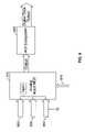
- FIG. 1Billustrates a behind-the-ear (BTE) cochlear stimulation system that includes an implanted cochlear stimulator (ICS) and an external BTE unit that includes a power source, a speech processor and a microphone.
- BTEbehind-the-ear
- FIG. 2is a flow chart depicting a method for obtaining reference data for use in determining flap thickness.
- FIG. 3is a flow chart depicting a method for obtaining reference data for use in determining flap thickness in accordance with another embodiment.
- FIG. 4is a flow chart depicting a method for estimating flap thickness for a cochlear stimulation system.
- FIG. 5is a graph depicting a measurement of an individual's flap thickness plotted against three reference measurements taken at three power levels.
- FIG. 6is a diagram of one embodiment of an analog-to-digital conversion system associated with an implantable cochlear stimulator.
- FIGS. 1A and 1BAn overview of an exemplary cochlear stimulation system is provided below in connection with FIGS. 1A and 1B .
- the following descriptionis exemplary and the devices, systems, and methods described herein can be used with other types and other configurations of cochlear stimulation systems.
- a representative cochlear stimulation system of the type currently used by many patientsis fully described, e.g., in U.S. Pat. No. 5,776,172 (“the '172 patent”), incorporated herein by reference.
- the external componentsinclude a speech processor (SP), a power source (e.g., a replaceable battery), and a headpiece (HP) 106 .
- the SP and power sourceare typically housed within a wearable unit 102 that is worn or carried by the patient.
- the wearable unitis electrically connected to the HP 106 via a cable 104 .
- a microphone 107is also included as part of the headpiece 106 .
- the implanted componentsinclude an implantable cochlear stimulator (ICS) 112 and an array of electrodes 114 .
- the electrode array 114is intended for implantation within the cochlear of the patient.
- the ICS 112is implanted behind the ear, so as to reside near the scalp.
- the electrode array 114is permanently connected to the ICS by way of a multi-conductor implantable cable 116 .
- a coilTransmitter
- a similar coilreceiveriver
- the external coil within the headpiecebe properly aligned with the internal coil inside the ICS.
- a magnetis typically included within both the headpiece 106 and the ICS 112 , and the resulting magnetic attraction between the two magnets not only aligns the coils, as desired, but also provides a holding force that maintains the headpiece 106 securely against the scalp or skin flap 110 of the patient.
- a carrier signalis generated by circuitry within the wearable unit 102 using energy derived from the power source within the speech processor unit 102 .
- Such carrier signalwhich is an AC signal, is conveyed over the cable to the headpiece 106 where it is inductively coupled to the coil within the ICS 112 . There it is rectified and filtered and provides a DC power source for operation of the circuitry within the ICS 112 .
- Soundsare sensed through the external microphone 107 , amplified and processed by circuitry included within the speech processor unit 102 , and converted to appropriate stimulation signals in accordance with a selected speech processing strategy by circuitry within the speech processor unit 102 .
- These stimulation signalsmodulate the carrier signal that transfers power to the ICS 112 .
- the ICSincludes an appropriate demodulation circuit that recovers the stimulation signals from the modulated carrier and applies them to the electrodes within the electrode array 114 .
- the stimulation signalsidentify which electrodes, or electrode pairs, are to be stimulated, the sequence of stimulation and the intensity of the stimulation.
- Some embodiments of the ICS 112include a back telemetry feature that allows data signals to be transmitted from the ICS 112 to the headpiece 106 , and hence to the Speech Processor 102 .
- Such back telemetry dataprovides important feedback information to the speech processor regarding the operation of the ICS, including the amount of power needed by the ICS. See, e.g., U.S. Pat. No. 5,876,425, issued to the same assignee as the present application, and also incorporated herein by reference.
- an external programming unit 108is detachably connected to the SP unit 102 .
- a clinicianor other medical personnel, is able to select the best speech processing strategy for the patient, as well as set other variables associated with the stimulation process. See, e.g., U.S. Pat. No. 5,626,629, incorporated herein by reference, for a description of a representative fitting/diagnostic process.
- FIG. 1Bdepicts a behind-the-ear (BTE) unit 120 .
- the BTE unit 120may include everything that was previously included within the wearable unit 102 , only in a much smaller volume.
- the BTE unit 120thus includes a suitable power source, as well as the circuitry needed for performing a desired speech processing function. With the BTE unit 120 , there is thus no need for the cable 104 , and the patient simply wears the BTE unit behind his or her ear, where it is hardly noticed, especially if the patient has hair to cover the BTE unit.
- the batteries employed within the wearable unit 102 ( FIG. 1A ) or the BTE unit 120 ( FIG. 1B )may be readily replaced when needed.
- the present inventorsrecognized a need to determine the skin flap 110 thickness in a noninvasive and convenient manner. Measurements of flap 110 thickness enable the design of RF systems for cochlear stimulation systems that are optimized for the average patient while still covering the range of distances between the transmitter in the HP 106 or SP/PWR 120 and receiver in the ICS 112 .
- FIG. 2is a flowchart that depicts a method for obtaining reference data for use in determining flap thickness.
- a first series of steps for obtaining data representing tank voltage measurements associated with a first flap simulator having a known thicknessis shown at 200 .
- a second series of steps for obtaining data representing tank voltage measurements associated with a flap simulator having a known thickness that is different from the flap simulator used in 200is shown at 300 .
- a third series of steps for obtaining data representing tank voltage measurements associated with a flap simulator having a known thickness that is different from the flap simulator used in 200 and 300is shown at 400 .
- the three series of steps 200 , 300 and 400can be performed substantially simultaneously as shown in FIG.
- steps 200 - 280may be performed prior to steps 300 - 380 , which may be performed prior to steps 400 - 480 .
- steps 400 - 480may be performed first followed by steps 200 - 280 or 300 - 380 .
- steps 300 - 380may be performed first followed by steps 200 - 280 or 400 - 480 .
- Steps 200 - 280will next be discussed.
- a flap simulator of a known thicknessis used to simulate a human flap of skin just behind the ear.
- a reference cochlear stimulation systemin accordance with those described herein is used.
- the flap simulatoris placed in between a transmitter and receiver of the reference cochlear stimulation system.
- the transmitterwould be secured to the outside of the individual's head and the receiver would be implanted underneath the skin flap juxtaposed with the transmitter.
- an implanted cochlear stimulation systemis simulated by placing the flap simulator in between the transmitter and receiver. Energy is transmitted by the transmitter through the flap simulator to the receiver at a first power level P 1 at 210 .
- the energy transmittedcan be RF energy or any other type of suitable telemetric energy.
- Tank voltage datawhich is a measure of transfer efficiency, is transmitted back to the transmitter from the receiver and received by a microprocessor at 220 .
- the datais stored by the microprocessor at 225 .
- Poweris increased at 230 and a corresponding energy transmitted again by the transmitter through the flap simulator to the receiver at 240 at a second power level P 2 .
- Tank voltage datais transmitted back to the transmitter from the receiver and received by the microprocessor at 250 .
- the datais stored by the microprocessor at 255 .
- Poweris increased again at 260 and a corresponding energy transmitted again by the transmitter through the flap simulator to the receiver at 270 at a third power level P 3 .
- Tank voltageis transmitted back to the transmitter from the receiver and received by the microprocessor at 280 .
- the datais stored by the microprocessor at 285 .
- Steps 260 - 280can be repeated an n number of times with an increase in power each time to collect as much reference data as is practicable or necessary.
- Steps 310 - 380can be carried out simultaneously with steps 210 - 280 , before steps 210 - 280 , or after steps 210 - 280 as shown in FIG. 2 .
- Steps 310 - 380are identical to steps 210 - 280 except that the flap simulator that is used has a different thickness from the flap simulator used in steps 210 - 280 .
- the flap simulatorcan either be thicker than or thinner than the flap simulator used in steps 210 - 280 . Altering the distance between the transmitter and receiver by altering the thickness of the flap simulator is one way to vary the stimulation load that is applied.
- one flap simulatorthat has an adjustable thickness can be used for both series of steps, with the thickness adjusted so that it varies between steps 210 - 280 and 310 - 380 .
- Steps 360 - 380can be repeated an n number of times with an increase in power each time to collect as much reference data as is practicable or necessary.
- steps 310 - 380can be performed under conditions in which the current being applied is varied as well.
- steps 310 - 380would be identical to steps 210 - 280 except that an increased or a decreased level of current is applied in addition to using a flap simulator having a thickness that is different from the one used in steps 210 - 280 .
- Steps 410 - 480can be carried out simultaneously with steps 210 - 280 and/or steps 310 - 380 , before steps 210 - 280 and/or 310 - 380 , or after steps 210 - 280 and/or 310 - 380 .
- the three respective series of steps, 210 - 280 , 310 - 380 , and 410 - 480can be carried at any time with respect to one another as shown in FIG. 2 .
- Steps 410 - 480are identical to steps 210 - 280 and 310 - 380 except that the flap simulator that is used has a different thickness from the flap simulators used in steps 210 - 280 and 310 - 380 .
- Altering the distance between the transmitter and receiver by altering the thickness of the flap simulatoris one way to vary the stimulation load that is applied.
- one flap simulator that has an adjustable thicknesscan be sued for all three series of steps, with the thickness adjusted so that it varies between steps 210 - 280 , 310 - 380 and 410 - 480 .
- Steps 460 - 480can be repeated an n number of times with an increase in power each time to collect as much reference data as is practicable or necessary.
- steps 410 - 480can be performed under conditions in which the current being applied is varied as well.
- steps 410 - 480would be identical to steps 210 - 280 and 310 - 380 except that an increased or a decreased level of current is applied in addition to using a flap simulator having a thickness that is different from the ones used in steps 210 - 280 and 310 - 380 .
- tank voltage datais obtained and stored. This data is later used as reference or calibration data to estimate flap thickness for patient's that use implanted cochlear stimulation systems.
- the method described in FIG. 2is one exemplary embodiment of a method of obtaining reference or calibration data, in which reference data at three different power levels and three different stimulation loads (i.e., flap simulator thicknesses and/or current levels) are used.
- Other embodimentsmay use as few as two power levels and two stimulation loads (i.e., different flap simulator thicknesses or current levels) or as many as five, six, seven, eight, nine, ten or n number of power levels and stimulation loads, with n representing any number above ten.
- FIG. 3represents another method of obtaining reference or calibration data.
- a flap simulator of a known thicknessis used to simulate a human flap of skin just behind the ear.
- a reference cochlear stimulation systemin accordance with those described herein is used.
- the flap simulatoris placed in between a transmitter (SP & PWR) and receiver (ICS) of the reference cochlear stimulation system.
- the transmitterwould be secured to the outside of the individual's head and the receiver would be implanted underneath the skin flap juxtaposed with the transmitter.
- an implanted cochlear stimulation systemis simulated by placing the flap simulator in between the transmitter and receiver.
- Tank voltage datawhich is a measure of transfer efficiency, is transmitted back to the transmitter from the receiver and received by a microprocessor integrated with the speech processor and power source (PROG).
- PROGspeech processor and power source
- the datais stored by the microprocessor for later use.
- the microprocessormay alternatively be a standalone computer that communicates directly with the headpeace speech processor and power source in any manner known to those of skill in the art, such as through a wireless, serial, or parallel connection.
- tank voltage datacan be varied across a predetermined range while recording tank voltage data. This can be accomplished in a continuous process or a sequential process. In either case, tank voltage data is transmitted, either continuously or sequentially, to the transmitter from the receiver and received by the microprocessor. By varying current while measuring tank voltage data, additional data points are gathered for later correlation with data received from human subjects who are fitted for cochlear implants and/or cochlear implant magnets.
- a difference between steps 500 , 600 , and 700is that the flap simulator has a different thickness in each step.
- the flap thickness of the flap simulatoris depicted as increasing from step 500 to 700 , with the flap simulator having the greatest thickness at step 700 .
- Steps 500 - 700can be performed sequentially as shown in FIG. 3 , simultaneously, or at different times in random order. If they are performed simultaneously, then three separate flap simulators having three different thicknesses can be used. If they are performed sequentially or at different times, then one flap simulator that has an adjustable thickness can be used for all three steps, with the thickness adjusted so that it varies between steps 500 , 600 , and 700 .
- any of steps 500 - 700can be repeated an n number of times using a different power level (i.e., RF strength) each time in a predetermined range of power levels so that tank voltage data for different powers levels and different loads can be collected and used as reference or calibration data. This can be accomplished in a continuous process or a sequential process in which both power level and current are being varied while collecting tank voltage data.
- a different power leveli.e., RF strength
- FIG. 4is a flowchart showing steps associated with a method of estimating flap thickness.
- the first stepis to implant a cochlear stimulation system, such as any one of those described herein or incorporated herein by reference.
- a cochlear stimulation systemsuch as any one of those described herein or incorporated herein by reference.
- an implantable cochlear stimulator 112is implanted underneath a flap of skin behind an individual's ear.
- a headpeace 106 or speech processor and power source 120is secured against the individual's head juxtaposed with the ICS 112 on the outer side of the flap of skin.
- step 800energy is transmitted at a first known power level by the transmitter associated with the headpeace or speech processor and power source across the individual's flap of skin and to the receiver associated with the ICS on the other side of the skin flap. Stimulating current transmitted at step 800 may also be a known value.
- Tank voltage datais transmitted back to the transmitter from the receiver and received by a microprocessor in communication with the cochlear stimulation system at 810 .
- the tank voltage datais stored by the microprocessor at 815 .
- the microprocessorcan be a standalone computer that communicates directly with the headpeace 106 or speech processor and power source 120 in any manner known to those of skill in the art, such as through a wireless, serial, or parallel connection.
- the microprocessorcan be integrated with the headpeace 106 or speech processor and power source 120 .
- the microprocessoreither has a display integrated with it, or communicates with a display.
- energyis transmitted at a second known power level different from the first power level by the transmitter across the individual's skin flap and to the receiver on the other side of the skin flap.
- Stimulation currentmay also be a known value that is either the same or different from the stimulation current applied at step 800 .
- Tank voltage datais transmitted back to the transmitter from the receiver and received by the microprocessor at 830 .
- Tank voltage datais stored by the microprocessor at 835 .
- step 840energy is transmitted at a third known power level different from the first and second power levels by the transmitter across the individual's skin flap and to the receiver on the other side of the skin flap.
- Stimulation currentmay also be a known value that is either the same as or different from the stimulation current applied at steps 800 and 820 .
- Tank voltage datais transmitted back to the transmitter from the receiver and received by the microprocessor at 850 .
- Tank voltage datais stored by the microprocessor at 855 .
- the datais correlated with the reference or calibration data obtained by the processes described above and processed at 860 .
- An estimate of the thickness of the individual's flap of skinis displayed on a display at 870 .
- steps 800 , 820 , and 840can correspond with the power levels transmitted during the acquisition of calibration or reference data, but this is not a strict requirement. Also, steps 800 - 815 , 820 - 835 and 840 - 855 , may be replicated an n number of times to obtain an n number of sets of tank voltage data with the power level changing each time.
- steps 840 - 855may be eliminated, consequently obtaining only two sets of tank voltage data to correlate with reference data.
- steps 820 - 855may be eliminated, consequently obtaining only one set of tank voltage data to correlate with reference data.
- the solid linesrepresent calibration or reference data at three power levels and one stimulation load.
- the individual's tank voltageis plotted with the horizontal lines and the point of intersection of these lines with the corresponding calibration line is the estimate flap thickness.
- Tank voltages that are either too low or too high (due to saturation)can be discarded in the estimation.
- Statistical methods(such as a median) may be used to calculate a value.
- Ambiguities in the correct resultsince there can be two points of intersection with the calibration data, can be resolved by observing an increase or decrease in tank voltage with increasing load. Load can be either distance or stimulation. Increasing tank voltage would indicate that the lower estimate is correct.
- FIG. 6is a diagram of an implementation of an analog-to-digital conversion (ADC) system associated with an implantable cochlear stimulator, such as the ICS 112 shown in FIGS. 1A and 1B .
- the INPUT multiplexor 910(“the MUX”) when performing the flap thickness estimation technique described here, is used to shunt current away from the stimulation electrodes 920 .
- the MUX 910is an analog multiplexor, but it could be digital instead in other implementations.
- the MUX 910has the ability, through application of appropriate control signals 915 , to connect together all of its input signals and its output signals simultaneously.
- All of the electrodesincluding the stimulation electrodes 920 , the stapedius electrodes 930 and the indifferent (ground) electrodes 940 , which are connected to signal ground, are substantially simultaneously connected to the outputs of MUX 910 , which is connected to an A/D subsystem 950 .
- the impedance to current flow through the MUX 910 to ground 940is much smaller than the impedance through the stimulation electrodes 920 and tissue and back through the ground electrodes 940 .
- the whole ADC system depicted in FIG. 6can be implemented on a single application specific integrated circuit (ASIC).
- ASICapplication specific integrated circuit
Landscapes
- Health & Medical Sciences (AREA)
- Life Sciences & Earth Sciences (AREA)
- Public Health (AREA)
- Otolaryngology (AREA)
- Engineering & Computer Science (AREA)
- Biomedical Technology (AREA)
- Veterinary Medicine (AREA)
- Animal Behavior & Ethology (AREA)
- General Health & Medical Sciences (AREA)
- Radiology & Medical Imaging (AREA)
- Nuclear Medicine, Radiotherapy & Molecular Imaging (AREA)
- Dermatology (AREA)
- Physics & Mathematics (AREA)
- Biophysics (AREA)
- Pathology (AREA)
- Heart & Thoracic Surgery (AREA)
- Medical Informatics (AREA)
- Molecular Biology (AREA)
- Surgery (AREA)
- Prostheses (AREA)
Abstract
Description
Claims (30)
Priority Applications (2)
| Application Number | Priority Date | Filing Date | Title |
|---|---|---|---|
| US11/016,604US7450994B1 (en) | 2004-12-16 | 2004-12-16 | Estimating flap thickness for cochlear implants |
| US12/244,082US7920924B2 (en) | 2004-12-16 | 2008-10-02 | Estimating flap thickness for cochlear implants |
Applications Claiming Priority (1)
| Application Number | Priority Date | Filing Date | Title |
|---|---|---|---|
| US11/016,604US7450994B1 (en) | 2004-12-16 | 2004-12-16 | Estimating flap thickness for cochlear implants |
Related Child Applications (1)
| Application Number | Title | Priority Date | Filing Date |
|---|---|---|---|
| US12/244,082ContinuationUS7920924B2 (en) | 2004-12-16 | 2008-10-02 | Estimating flap thickness for cochlear implants |
Publications (1)
| Publication Number | Publication Date |
|---|---|
| US7450994B1true US7450994B1 (en) | 2008-11-11 |
Family
ID=39940883
Family Applications (2)
| Application Number | Title | Priority Date | Filing Date |
|---|---|---|---|
| US11/016,604Expired - Fee RelatedUS7450994B1 (en) | 2004-12-16 | 2004-12-16 | Estimating flap thickness for cochlear implants |
| US12/244,082Expired - Fee RelatedUS7920924B2 (en) | 2004-12-16 | 2008-10-02 | Estimating flap thickness for cochlear implants |
Family Applications After (1)
| Application Number | Title | Priority Date | Filing Date |
|---|---|---|---|
| US12/244,082Expired - Fee RelatedUS7920924B2 (en) | 2004-12-16 | 2008-10-02 | Estimating flap thickness for cochlear implants |
Country Status (1)
| Country | Link |
|---|---|
| US (2) | US7450994B1 (en) |
Cited By (23)
| Publication number | Priority date | Publication date | Assignee | Title |
|---|---|---|---|---|
| US20050137651A1 (en)* | 2003-11-21 | 2005-06-23 | Litvak Leonid M. | Optimizing pitch allocation in a cochlear implant |
| US20060280655A1 (en)* | 2005-06-08 | 2006-12-14 | California Institute Of Technology | Intravascular diagnostic and therapeutic sampling device |
| US20090187237A1 (en)* | 2004-11-17 | 2009-07-23 | Advanced Bionics, Llc | Inner Hair Cell Stimulation Model for Use by a Cochlear Implant System |
| US20090222064A1 (en)* | 2005-07-08 | 2009-09-03 | Advanced Bionics, Llc | Autonomous Autoprogram Cochlear Implant |
| US7599500B1 (en) | 2004-12-09 | 2009-10-06 | Advanced Bionics, Llc | Processing signals representative of sound based on the identity of an input element |
| US7729775B1 (en) | 2006-03-21 | 2010-06-01 | Advanced Bionics, Llc | Spectral contrast enhancement in a cochlear implant speech processor |
| US20100179616A1 (en)* | 2004-12-03 | 2010-07-15 | Advanced Bionics, Llc | Outer Hair Cell Stimulation Model for the Use by an Intra-Cochlear Implant |
| US20100249885A1 (en)* | 2005-01-20 | 2010-09-30 | Boston Scientific Neuromodulation Corporation | Implantable microstimulator with plastic housing and methods of manufacture and use |
| US20100292759A1 (en)* | 2005-03-24 | 2010-11-18 | Hahn Tae W | Magnetic field sensor for magnetically-coupled medical implant devices |
| US20110069853A1 (en)* | 2006-09-25 | 2011-03-24 | Advanced Bionics, Llc | Auditory Front End Customization |
| US7995771B1 (en) | 2006-09-25 | 2011-08-09 | Advanced Bionics, Llc | Beamforming microphone system |
| US8027733B1 (en) | 2005-10-28 | 2011-09-27 | Advanced Bionics, Llc | Optimizing pitch allocation in a cochlear stimulation system |
| CN102970648A (en)* | 2012-12-14 | 2013-03-13 | 杭州诺尔康神经电子科技有限公司 | Program downloading and measuring system for PCB (printed circuit board) of signal processing unit |
| US8548604B2 (en) | 2002-06-20 | 2013-10-01 | Boston Scientific Neuromodulation Corporation | Implantable microstimulators and methods for unidirectional propagation of action potentials |
| US8712547B2 (en) | 2002-06-20 | 2014-04-29 | Boston Scientific Neuromodulation Corporation | Cavernous nerve stimulation via unidirectional propagation of action potentials |
| US8818517B2 (en) | 2006-05-05 | 2014-08-26 | Advanced Bionics Ag | Information processing and storage in a cochlear stimulation system |
| WO2015147774A1 (en)* | 2014-03-22 | 2015-10-01 | Advanced Bionics Ag | Headpieceless hearing assistance apparatus, systems and methods with distributed power |
| US9393421B2 (en) | 2005-05-26 | 2016-07-19 | Boston Scientific Neuromodulation Corporation | Controlling charge flow in the electrical stimulation of tissue |
| US9409028B2 (en) | 2002-06-20 | 2016-08-09 | Boston Scientific Neuromodulation Corporation | Implantable microstimulators with programmable multielectrode configuration and uses thereof |
| US20160375242A1 (en)* | 2014-03-12 | 2016-12-29 | Advanced Bionics Ag | Implantable hearing assistance apparatus and corresponding systems and methods |
| US10195444B2 (en) | 2014-03-22 | 2019-02-05 | Advanced Bionics Ag | Implantable hearing assistance apparatus and corresponding systems and methods |
| WO2022079505A1 (en)* | 2020-10-13 | 2022-04-21 | Cochlear Limited | Skin flap thickness estimation |
| WO2022218538A1 (en) | 2021-04-16 | 2022-10-20 | Advanced Bionics Ag | Hearing prosthesis system and method of operating the same |
Families Citing this family (6)
| Publication number | Priority date | Publication date | Assignee | Title |
|---|---|---|---|---|
| US9467690B2 (en) | 2010-01-06 | 2016-10-11 | Dolby Laboratories Licensing Corporation | Complexity-adaptive scalable decoding and streaming for multi-layered video systems |
| US11369283B2 (en) | 2013-10-24 | 2022-06-28 | Med-El Elektromedizinische Geraete Gmbh | Implant magnet distance determination |
| WO2016035026A1 (en) | 2014-09-02 | 2016-03-10 | Cochlear Limited | Event detection in an implantable auditory prosthesis |
| US10482983B2 (en)* | 2016-12-22 | 2019-11-19 | Seagate Technology Llc | Read disturb detection based on dynamic bit error rate estimation |
| WO2024084333A1 (en)* | 2022-10-17 | 2024-04-25 | Cochlear Limited | Techniques for measuring skin flap thickness using ultrasound |
| WO2025062267A1 (en)* | 2023-09-22 | 2025-03-27 | Cochlear Limited | Systems and methods for estimating skin flap thickness |
Citations (110)
| Publication number | Priority date | Publication date | Assignee | Title |
|---|---|---|---|---|
| US3522811A (en) | 1969-02-13 | 1970-08-04 | Medtronic Inc | Implantable nerve stimulator and method of use |
| US3751605A (en) | 1972-02-04 | 1973-08-07 | Beckman Instruments Inc | Method for inducing hearing |
| USRE30366E (en) | 1970-09-21 | 1980-08-12 | Rasor Associates, Inc. | Organ stimulator |
| US4400590A (en) | 1980-12-22 | 1983-08-23 | The Regents Of The University Of California | Apparatus for multichannel cochlear implant hearing aid system |
| US4414979A (en) | 1981-02-23 | 1983-11-15 | Telectronics Pty. Ltd. | Monitorable bone growth stimulator |
| US4495384A (en) | 1982-08-23 | 1985-01-22 | Scott Instruments Corporation | Real time cochlear implant processor |
| US4573481A (en) | 1984-06-25 | 1986-03-04 | Huntington Institute Of Applied Research | Implantable electrode array |
| US4612934A (en) | 1981-06-30 | 1986-09-23 | Borkan William N | Non-invasive multiprogrammable tissue stimulator |
| US4793353A (en) | 1981-06-30 | 1988-12-27 | Borkan William N | Non-invasive multiprogrammable tissue stimulator and method |
| US4819647A (en) | 1984-05-03 | 1989-04-11 | The Regents Of The University Of California | Intracochlear electrode array |
| US4905285A (en) | 1987-04-03 | 1990-02-27 | American Telephone And Telegraph Company, At&T Bell Laboratories | Analysis arrangement based on a model of human neural responses |
| US5002053A (en) | 1989-04-21 | 1991-03-26 | University Of Arkansas | Method of and device for inducing locomotion by electrical stimulation of the spinal cord |
| US5042084A (en)* | 1989-09-07 | 1991-08-20 | Cochlear Pty. Limited | Three wire system for Cochlear implant processor |
| US5105811A (en) | 1982-07-27 | 1992-04-21 | Commonwealth Of Australia | Cochlear prosthetic package |
| US5193540A (en) | 1991-12-18 | 1993-03-16 | Alfred E. Mann Foundation For Scientific Research | Structure and method of manufacture of an implantable microstimulator |
| US5211175A (en) | 1988-11-07 | 1993-05-18 | Regents Of The University Of California | Method for implanting electra-acupuncture needle |
| US5257634A (en) | 1992-07-16 | 1993-11-02 | Angeion Corporation | Low impedence defibrillation catheter electrode |
| US5358514A (en) | 1991-12-18 | 1994-10-25 | Alfred E. Mann Foundation For Scientific Research | Implantable microdevice with self-attaching electrodes |
| US5366493A (en) | 1991-02-04 | 1994-11-22 | Case Western Reserve University | Double helix functional stimulation electrode |
| US5479522A (en) | 1993-09-17 | 1995-12-26 | Audiologic, Inc. | Binaural hearing aid |
| US5591217A (en) | 1995-01-04 | 1997-01-07 | Plexus, Inc. | Implantable stimulator with replenishable, high value capacitive power source and method therefor |
| US5601617A (en) | 1995-04-26 | 1997-02-11 | Advanced Bionics Corporation | Multichannel cochlear prosthesis with flexible control of stimulus waveforms |
| US5603726A (en) | 1989-09-22 | 1997-02-18 | Alfred E. Mann Foundation For Scientific Research | Multichannel cochlear implant system including wearable speech processor |
| US5626629A (en) | 1995-05-31 | 1997-05-06 | Advanced Bionics Corporation | Programming of a speech processor for an implantable cochlear stimulator |
| US5721783A (en) | 1995-06-07 | 1998-02-24 | Anderson; James C. | Hearing aid with wireless remote processor |
| US5741316A (en) | 1996-12-02 | 1998-04-21 | Light Sciences Limited Partnership | Electromagnetic coil configurations for power transmission through tissue |
| US5776172A (en) | 1989-09-22 | 1998-07-07 | Alfred E. Mann Foundation For Scientific Research | Multichannel implantable cochlear stimulator |
| US5824022A (en) | 1996-03-07 | 1998-10-20 | Advanced Bionics Corporation | Cochlear stimulation system employing behind-the-ear speech processor with remote control |
| US5876425A (en) | 1989-09-22 | 1999-03-02 | Advanced Bionics Corporation | Power control loop for implantable tissue stimulator |
| US5938691A (en) | 1989-09-22 | 1999-08-17 | Alfred E. Mann Foundation | Multichannel implantable cochlear stimulator |
| US5991419A (en) | 1997-04-29 | 1999-11-23 | Beltone Electronics Corporation | Bilateral signal processing prosthesis |
| US5991664A (en) | 1997-03-09 | 1999-11-23 | Cochlear Limited | Compact inductive arrangement for medical implant data and power transfer |
| WO2000001200A1 (en) | 1998-06-30 | 2000-01-06 | University Of Stirling | Method and apparatus for processing sound |
| US6052624A (en) | 1999-01-07 | 2000-04-18 | Advanced Bionics Corporation | Directional programming for implantable electrode arrays |
| US6064913A (en) | 1997-04-16 | 2000-05-16 | The University Of Melbourne | Multiple pulse stimulation |
| US6067474A (en) | 1997-08-01 | 2000-05-23 | Advanced Bionics Corporation | Implantable device with improved battery recharging and powering configuration |
| US6078838A (en) | 1998-02-13 | 2000-06-20 | University Of Iowa Research Foundation | Pseudospontaneous neural stimulation system and method |
| US6092531A (en) | 1998-02-10 | 2000-07-25 | Light Sciences Limited Partnership | Movable magnet transmitter for inducing electrical current in an implanted coil |
| US6129753A (en) | 1998-03-27 | 2000-10-10 | Advanced Bionics Corporation | Cochlear electrode array with electrode contacts on medial side |
| US6154678A (en) | 1999-03-19 | 2000-11-28 | Advanced Neuromodulation Systems, Inc. | Stimulation lead connector |
| US6154677A (en) | 1998-08-20 | 2000-11-28 | Implex Aktiengesellschaft Hearing Technology | Implantable device with a charging current feed arrangement which has a receiving coil |
| US6157861A (en) | 1996-06-20 | 2000-12-05 | Advanced Bionics Corporation | Self-adjusting cochlear implant system and method for fitting same |
| US6181969B1 (en) | 1998-06-26 | 2001-01-30 | Advanced Bionics Corporation | Programmable current output stimulus stage for implantable device |
| US6185452B1 (en) | 1997-02-26 | 2001-02-06 | Joseph H. Schulman | Battery-powered patient implantable device |
| US6195585B1 (en) | 1998-06-26 | 2001-02-27 | Advanced Bionics Corporation | Remote monitoring of implantable cochlear stimulator |
| US6198971B1 (en) | 1999-04-08 | 2001-03-06 | Implex Aktiengesellschaft Hearing Technology | Implantable system for rehabilitation of a hearing disorder |
| US6205360B1 (en) | 1995-09-07 | 2001-03-20 | Cochlear Limited | Apparatus and method for automatically determining stimulation parameters |
| US6208882B1 (en) | 1998-06-03 | 2001-03-27 | Advanced Bionics Corporation | Stapedius reflex electrode and connector |
| US6216045B1 (en) | 1999-04-26 | 2001-04-10 | Advanced Neuromodulation Systems, Inc. | Implantable lead and method of manufacture |
| US6219580B1 (en) | 1995-04-26 | 2001-04-17 | Advanced Bionics Corporation | Multichannel cochlear prosthesis with flexible control of stimulus waveforms |
| US6246911B1 (en) | 1999-02-08 | 2001-06-12 | Peter Seligman | Cochlear implants with offset coils for transmission of radio frequency links |
| US6249704B1 (en) | 1998-08-11 | 2001-06-19 | Advanced Bionics Corporation | Low voltage stimulation to elicit stochastic response patterns that enhance the effectiveness of a cochlear implant |
| US6272382B1 (en) | 1998-07-31 | 2001-08-07 | Advanced Bionics Corporation | Fully implantable cochlear implant system |
| US6289247B1 (en) | 1998-06-02 | 2001-09-11 | Advanced Bionics Corporation | Strategy selector for multichannel cochlear prosthesis |
| US6295467B1 (en) | 1996-07-18 | 2001-09-25 | Birger Kollmeier | Method and device for detecting a reflex of the human stapedius muscle |
| US20010031909A1 (en) | 2000-03-31 | 2001-10-18 | Faltys Michael A. | High contact count, sub-miniature, fully implantable cochlear prosthesis |
| US6308101B1 (en) | 1998-07-31 | 2001-10-23 | Advanced Bionics Corporation | Fully implantable cochlear implant system |
| WO2002009808A1 (en) | 2000-07-26 | 2002-02-07 | Advanced Bionics Corporation | Rechargeable spinal cord stimulator system |
| US6393325B1 (en) | 1999-01-07 | 2002-05-21 | Advanced Bionics Corporation | Directional programming for implantable electrode arrays |
| US6415185B1 (en) | 1998-09-04 | 2002-07-02 | Advanced Bionics Corporation | Objective programming and operation of a Cochlear implant based on measured evoked potentials that precede the stapedius reflex |
| US6449372B1 (en) | 1999-01-05 | 2002-09-10 | Phonak Ag | Method for matching hearing aids binaurally |
| US6516227B1 (en) | 1999-07-27 | 2003-02-04 | Advanced Bionics Corporation | Rechargeable spinal cord stimulator system |
| US20030036782A1 (en) | 2001-08-20 | 2003-02-20 | Hartley Lee F. | BioNet for bilateral cochlear implant systems |
| WO2003015863A3 (en) | 2001-08-17 | 2003-04-03 | Advanced Bionics Corp | Gradual recruitment of muscle/neural excitable tissue using high-rate electrical stimulation parameters |
| US6549633B1 (en) | 1998-02-18 | 2003-04-15 | Widex A/S | Binaural digital hearing aid system |
| US20030097254A1 (en) | 2001-11-06 | 2003-05-22 | The Regents Of The University Of California | Ultra-narrow bandwidth voice coding |
| US20030114905A1 (en) | 1999-10-01 | 2003-06-19 | Kuzma Janusz A. | Implantable microdevice with extended lead and remote electrode |
| US20030198953A1 (en) | 2000-03-30 | 2003-10-23 | Spytek Kimberly A. | Novel proteins and nucleic acids encoding same |
| US20040015204A1 (en) | 2002-06-20 | 2004-01-22 | Whitehurst Todd K. | Implantable microstimulators and methods for unidirectional propagation of action potentials |
| US20040015205A1 (en) | 2002-06-20 | 2004-01-22 | Whitehurst Todd K. | Implantable microstimulators with programmable multielectrode configuration and uses thereof |
| US6700982B1 (en) | 1998-06-08 | 2004-03-02 | Cochlear Limited | Hearing instrument with onset emphasis |
| US20040044383A1 (en) | 2002-08-30 | 2004-03-04 | Woods Carla Mann | Status indicator for implantable systems |
| US6728578B1 (en) | 2000-06-01 | 2004-04-27 | Advanced Bionics Corporation | Envelope-based amplitude mapping for cochlear implant stimulus |
| WO2004043537A1 (en) | 2002-11-13 | 2004-05-27 | Advanced Bionics Corporation | Method and system to convey the within-channel fine structure with a cochlear implant |
| US6810289B1 (en)* | 2000-04-20 | 2004-10-26 | Cochlear Limited | Transcutaneous power optimization circuit for cochlear implant |
| US6842647B1 (en) | 2000-10-20 | 2005-01-11 | Advanced Bionics Corporation | Implantable neural stimulator system including remote control unit for use therewith |
| US20050137650A1 (en) | 2003-11-21 | 2005-06-23 | Litvak Leonid M. | Methods and systems for fitting a cochlear implant to a patient |
| US20050137651A1 (en) | 2003-11-21 | 2005-06-23 | Litvak Leonid M. | Optimizing pitch allocation in a cochlear implant |
| US6915166B1 (en) | 1999-08-27 | 2005-07-05 | Cochlear Limited | Optimizing cochlear implant electrode selection |
| US20050209652A1 (en) | 2001-04-26 | 2005-09-22 | Whitehurst Todd K | Methods and systems for electrical and/or drug stimulation as a therapy for erectile dysfunction |
| US20050240229A1 (en) | 2001-04-26 | 2005-10-27 | Whitehurst Tood K | Methods and systems for stimulation as a therapy for erectile dysfunction |
| US20050267555A1 (en) | 2004-05-28 | 2005-12-01 | Marnfeldt Goran N | Engagement tool for implantable medical devices |
| US20060100672A1 (en) | 2004-11-05 | 2006-05-11 | Litvak Leonid M | Method and system of matching information from cochlear implants in two ears |
| US20060106446A1 (en) | 2004-11-17 | 2006-05-18 | Fridman Gene Y | Inner hair cell stimulation model for the use by an intra-cochlear implant |
| US20060161204A1 (en) | 2005-01-20 | 2006-07-20 | Advanced Bionics Corporation | Implantable microstimulator with plastic housing and methods of manufacture and use |
| US20060167521A1 (en) | 2005-01-26 | 2006-07-27 | He Tom X | Casings for implantable stimulators and methods of making the same |
| US20060184204A1 (en) | 2005-02-11 | 2006-08-17 | Advanced Bionics Corporation | Implantable microstimulator having a separate battery unit and methods of use thereof |
| US20060195143A1 (en) | 2005-02-25 | 2006-08-31 | Mcclure Kelly H | Multiple-pronged implantable stimulator and methods of making and using such a stimulator |
| US20060212087A1 (en) | 2005-03-15 | 2006-09-21 | Haller Matthew I | Implantable stimulator |
| US20060229688A1 (en) | 2005-04-08 | 2006-10-12 | Mcclure Kelly H | Controlling stimulation parameters of implanted tissue stimulators |
| US20060271109A1 (en) | 2005-05-25 | 2006-11-30 | Advanced Bionics Corporation | Implantable microstimulator with dissecting tip and/or retrieving anchor and methods of manufacture and use |
| US20070021800A1 (en) | 2002-06-20 | 2007-01-25 | Advanced Bionics Corporation, A California Corporation | Cavernous nerve stimulation via unidirectional propagation of action potentials |
| US20070019988A1 (en) | 2005-07-19 | 2007-01-25 | Xerox Corporation | Release fluid additives |
| US20070055308A1 (en) | 2005-09-06 | 2007-03-08 | Haller Matthew I | Ultracapacitor powered implantable pulse generator with dedicated power supply |
| US20070066997A1 (en) | 2005-09-21 | 2007-03-22 | He Tom X | Methods and systems for placing an implanted stimulator for stimulating tissue |
| US7200504B1 (en) | 2005-05-16 | 2007-04-03 | Advanced Bionics Corporation | Measuring temperature change in an electronic biomedical implant |
| US20070100395A1 (en)* | 2002-09-04 | 2007-05-03 | Ibrahim Ibrahim H | Method and apparatus for measurement of transmitter/receiver separation |
| WO2007059343A2 (en) | 2005-11-16 | 2007-05-24 | Boston Scientific Neuromodulation Corporation | Implantable stimulator configured to be implanted within a patient in a pre-determined orientation |
| US20070122403A1 (en) | 2000-12-12 | 2007-05-31 | Medimmune, Inc. | Molecules with extended half-lives, compositions and uses thereof |
| US20070123938A1 (en) | 2005-11-30 | 2007-05-31 | Haller Matthew I | Magnetically coupled microstimulators |
| US20070122404A1 (en) | 2005-11-17 | 2007-05-31 | O'keefe Theresa L | Humanized immunoglobulin reactive with alpha4beta7 integrin |
| US7242985B1 (en) | 2004-12-03 | 2007-07-10 | Advanced Bionics Corporation | Outer hair cell stimulation model for the use by an intra—cochlear implant |
| US20070219595A1 (en) | 2006-03-14 | 2007-09-20 | Advanced Bionics Corporation | Stimulator system with electrode array and the method of making the same |
| US7277760B1 (en) | 2004-11-05 | 2007-10-02 | Advanced Bionics Corporation | Encoding fine time structure in presence of substantial interaction across an electrode array |
| US7292890B2 (en) | 2002-06-20 | 2007-11-06 | Advanced Bionics Corporation | Vagus nerve stimulation via unidirectional propagation of action potentials |
| WO2007130782A1 (en) | 2006-05-05 | 2007-11-15 | Advanced Bionics, Llc | Information processing and storage in a cochlear stimulation system |
| US7308303B2 (en) | 2001-11-01 | 2007-12-11 | Advanced Bionics Corporation | Thrombolysis and chronic anticoagulation therapy |
| US20070293785A1 (en) | 2004-11-05 | 2007-12-20 | Litvak Leonid M | Encoding Fine Time Structure in Presence of Substantial Interaction Across An Electrode Array |
| US7347746B1 (en) | 2006-10-27 | 2008-03-25 | Boston Scientific Neuromodulation Corporation | Receptacle connector assembly |
| US20080085023A1 (en) | 2006-09-25 | 2008-04-10 | Abhijit Kulkarni | Auditory Front End Customization |
Family Cites Families (2)
| Publication number | Priority date | Publication date | Assignee | Title |
|---|---|---|---|---|
| US6212431B1 (en)* | 1998-09-08 | 2001-04-03 | Advanced Bionics Corporation | Power transfer circuit for implanted devices |
| US7623929B1 (en)* | 2002-08-30 | 2009-11-24 | Advanced Bionics, Llc | Current sensing coil for cochlear implant data detection |
- 2004
- 2004-12-16USUS11/016,604patent/US7450994B1/ennot_activeExpired - Fee Related
- 2008
- 2008-10-02USUS12/244,082patent/US7920924B2/ennot_activeExpired - Fee Related
Patent Citations (118)
| Publication number | Priority date | Publication date | Assignee | Title |
|---|---|---|---|---|
| US3522811A (en) | 1969-02-13 | 1970-08-04 | Medtronic Inc | Implantable nerve stimulator and method of use |
| USRE30366E (en) | 1970-09-21 | 1980-08-12 | Rasor Associates, Inc. | Organ stimulator |
| US3751605A (en) | 1972-02-04 | 1973-08-07 | Beckman Instruments Inc | Method for inducing hearing |
| US4400590A (en) | 1980-12-22 | 1983-08-23 | The Regents Of The University Of California | Apparatus for multichannel cochlear implant hearing aid system |
| US4414979A (en) | 1981-02-23 | 1983-11-15 | Telectronics Pty. Ltd. | Monitorable bone growth stimulator |
| US4612934A (en) | 1981-06-30 | 1986-09-23 | Borkan William N | Non-invasive multiprogrammable tissue stimulator |
| US4793353A (en) | 1981-06-30 | 1988-12-27 | Borkan William N | Non-invasive multiprogrammable tissue stimulator and method |
| US5105811A (en) | 1982-07-27 | 1992-04-21 | Commonwealth Of Australia | Cochlear prosthetic package |
| US4495384A (en) | 1982-08-23 | 1985-01-22 | Scott Instruments Corporation | Real time cochlear implant processor |
| US4819647A (en) | 1984-05-03 | 1989-04-11 | The Regents Of The University Of California | Intracochlear electrode array |
| US4573481A (en) | 1984-06-25 | 1986-03-04 | Huntington Institute Of Applied Research | Implantable electrode array |
| US4905285A (en) | 1987-04-03 | 1990-02-27 | American Telephone And Telegraph Company, At&T Bell Laboratories | Analysis arrangement based on a model of human neural responses |
| US5211175A (en) | 1988-11-07 | 1993-05-18 | Regents Of The University Of California | Method for implanting electra-acupuncture needle |
| US5002053A (en) | 1989-04-21 | 1991-03-26 | University Of Arkansas | Method of and device for inducing locomotion by electrical stimulation of the spinal cord |
| US5042084A (en)* | 1989-09-07 | 1991-08-20 | Cochlear Pty. Limited | Three wire system for Cochlear implant processor |
| US5776172A (en) | 1989-09-22 | 1998-07-07 | Alfred E. Mann Foundation For Scientific Research | Multichannel implantable cochlear stimulator |
| US5876425A (en) | 1989-09-22 | 1999-03-02 | Advanced Bionics Corporation | Power control loop for implantable tissue stimulator |
| US5603726A (en) | 1989-09-22 | 1997-02-18 | Alfred E. Mann Foundation For Scientific Research | Multichannel cochlear implant system including wearable speech processor |
| US5938691A (en) | 1989-09-22 | 1999-08-17 | Alfred E. Mann Foundation | Multichannel implantable cochlear stimulator |
| US5366493A (en) | 1991-02-04 | 1994-11-22 | Case Western Reserve University | Double helix functional stimulation electrode |
| US5358514A (en) | 1991-12-18 | 1994-10-25 | Alfred E. Mann Foundation For Scientific Research | Implantable microdevice with self-attaching electrodes |
| US5405367A (en) | 1991-12-18 | 1995-04-11 | Alfred E. Mann Foundation For Scientific Research | Structure and method of manufacture of an implantable microstimulator |
| US5193540A (en) | 1991-12-18 | 1993-03-16 | Alfred E. Mann Foundation For Scientific Research | Structure and method of manufacture of an implantable microstimulator |
| US5257634A (en) | 1992-07-16 | 1993-11-02 | Angeion Corporation | Low impedence defibrillation catheter electrode |
| US5479522A (en) | 1993-09-17 | 1995-12-26 | Audiologic, Inc. | Binaural hearing aid |
| US5591217A (en) | 1995-01-04 | 1997-01-07 | Plexus, Inc. | Implantable stimulator with replenishable, high value capacitive power source and method therefor |
| US5601617A (en) | 1995-04-26 | 1997-02-11 | Advanced Bionics Corporation | Multichannel cochlear prosthesis with flexible control of stimulus waveforms |
| US6002966A (en) | 1995-04-26 | 1999-12-14 | Advanced Bionics Corporation | Multichannel cochlear prosthesis with flexible control of stimulus waveforms |
| US6219580B1 (en) | 1995-04-26 | 2001-04-17 | Advanced Bionics Corporation | Multichannel cochlear prosthesis with flexible control of stimulus waveforms |
| US5626629A (en) | 1995-05-31 | 1997-05-06 | Advanced Bionics Corporation | Programming of a speech processor for an implantable cochlear stimulator |
| US5721783A (en) | 1995-06-07 | 1998-02-24 | Anderson; James C. | Hearing aid with wireless remote processor |
| US6205360B1 (en) | 1995-09-07 | 2001-03-20 | Cochlear Limited | Apparatus and method for automatically determining stimulation parameters |
| US5824022A (en) | 1996-03-07 | 1998-10-20 | Advanced Bionics Corporation | Cochlear stimulation system employing behind-the-ear speech processor with remote control |
| US6157861A (en) | 1996-06-20 | 2000-12-05 | Advanced Bionics Corporation | Self-adjusting cochlear implant system and method for fitting same |
| US6295467B1 (en) | 1996-07-18 | 2001-09-25 | Birger Kollmeier | Method and device for detecting a reflex of the human stapedius muscle |
| US5741316A (en) | 1996-12-02 | 1998-04-21 | Light Sciences Limited Partnership | Electromagnetic coil configurations for power transmission through tissue |
| US6185452B1 (en) | 1997-02-26 | 2001-02-06 | Joseph H. Schulman | Battery-powered patient implantable device |
| US5991664A (en) | 1997-03-09 | 1999-11-23 | Cochlear Limited | Compact inductive arrangement for medical implant data and power transfer |
| US6064913A (en) | 1997-04-16 | 2000-05-16 | The University Of Melbourne | Multiple pulse stimulation |
| US5991419A (en) | 1997-04-29 | 1999-11-23 | Beltone Electronics Corporation | Bilateral signal processing prosthesis |
| US6067474A (en) | 1997-08-01 | 2000-05-23 | Advanced Bionics Corporation | Implantable device with improved battery recharging and powering configuration |
| US6092531A (en) | 1998-02-10 | 2000-07-25 | Light Sciences Limited Partnership | Movable magnet transmitter for inducing electrical current in an implanted coil |
| US6078838A (en) | 1998-02-13 | 2000-06-20 | University Of Iowa Research Foundation | Pseudospontaneous neural stimulation system and method |
| US6549633B1 (en) | 1998-02-18 | 2003-04-15 | Widex A/S | Binaural digital hearing aid system |
| US6129753A (en) | 1998-03-27 | 2000-10-10 | Advanced Bionics Corporation | Cochlear electrode array with electrode contacts on medial side |
| US6289247B1 (en) | 1998-06-02 | 2001-09-11 | Advanced Bionics Corporation | Strategy selector for multichannel cochlear prosthesis |
| US6208882B1 (en) | 1998-06-03 | 2001-03-27 | Advanced Bionics Corporation | Stapedius reflex electrode and connector |
| US6700982B1 (en) | 1998-06-08 | 2004-03-02 | Cochlear Limited | Hearing instrument with onset emphasis |
| US6195585B1 (en) | 1998-06-26 | 2001-02-27 | Advanced Bionics Corporation | Remote monitoring of implantable cochlear stimulator |
| US6181969B1 (en) | 1998-06-26 | 2001-01-30 | Advanced Bionics Corporation | Programmable current output stimulus stage for implantable device |
| WO2000001200A1 (en) | 1998-06-30 | 2000-01-06 | University Of Stirling | Method and apparatus for processing sound |
| US6272382B1 (en) | 1998-07-31 | 2001-08-07 | Advanced Bionics Corporation | Fully implantable cochlear implant system |
| US6308101B1 (en) | 1998-07-31 | 2001-10-23 | Advanced Bionics Corporation | Fully implantable cochlear implant system |
| US6249704B1 (en) | 1998-08-11 | 2001-06-19 | Advanced Bionics Corporation | Low voltage stimulation to elicit stochastic response patterns that enhance the effectiveness of a cochlear implant |
| US6154677A (en) | 1998-08-20 | 2000-11-28 | Implex Aktiengesellschaft Hearing Technology | Implantable device with a charging current feed arrangement which has a receiving coil |
| US6415185B1 (en) | 1998-09-04 | 2002-07-02 | Advanced Bionics Corporation | Objective programming and operation of a Cochlear implant based on measured evoked potentials that precede the stapedius reflex |
| US6449372B1 (en) | 1999-01-05 | 2002-09-10 | Phonak Ag | Method for matching hearing aids binaurally |
| US6393325B1 (en) | 1999-01-07 | 2002-05-21 | Advanced Bionics Corporation | Directional programming for implantable electrode arrays |
| US6052624A (en) | 1999-01-07 | 2000-04-18 | Advanced Bionics Corporation | Directional programming for implantable electrode arrays |
| US6246911B1 (en) | 1999-02-08 | 2001-06-12 | Peter Seligman | Cochlear implants with offset coils for transmission of radio frequency links |
| US6154678A (en) | 1999-03-19 | 2000-11-28 | Advanced Neuromodulation Systems, Inc. | Stimulation lead connector |
| US6198971B1 (en) | 1999-04-08 | 2001-03-06 | Implex Aktiengesellschaft Hearing Technology | Implantable system for rehabilitation of a hearing disorder |
| US6216045B1 (en) | 1999-04-26 | 2001-04-10 | Advanced Neuromodulation Systems, Inc. | Implantable lead and method of manufacture |
| US6516227B1 (en) | 1999-07-27 | 2003-02-04 | Advanced Bionics Corporation | Rechargeable spinal cord stimulator system |
| US6915166B1 (en) | 1999-08-27 | 2005-07-05 | Cochlear Limited | Optimizing cochlear implant electrode selection |
| US20030114905A1 (en) | 1999-10-01 | 2003-06-19 | Kuzma Janusz A. | Implantable microdevice with extended lead and remote electrode |
| US20030198953A1 (en) | 2000-03-30 | 2003-10-23 | Spytek Kimberly A. | Novel proteins and nucleic acids encoding same |
| US20010031909A1 (en) | 2000-03-31 | 2001-10-18 | Faltys Michael A. | High contact count, sub-miniature, fully implantable cochlear prosthesis |
| US20040082985A1 (en) | 2000-03-31 | 2004-04-29 | Faltys Michael A. | High contact count, sub-miniature, fully implantable cochlear prosthesis |
| US6826430B2 (en) | 2000-03-31 | 2004-11-30 | Advanced Bionics Corporation | High contact count, sub-miniature, fully implantable cochlear prosthesis |
| US6810289B1 (en)* | 2000-04-20 | 2004-10-26 | Cochlear Limited | Transcutaneous power optimization circuit for cochlear implant |
| US6728578B1 (en) | 2000-06-01 | 2004-04-27 | Advanced Bionics Corporation | Envelope-based amplitude mapping for cochlear implant stimulus |
| WO2002009808A1 (en) | 2000-07-26 | 2002-02-07 | Advanced Bionics Corporation | Rechargeable spinal cord stimulator system |
| US6842647B1 (en) | 2000-10-20 | 2005-01-11 | Advanced Bionics Corporation | Implantable neural stimulator system including remote control unit for use therewith |
| US20070122403A1 (en) | 2000-12-12 | 2007-05-31 | Medimmune, Inc. | Molecules with extended half-lives, compositions and uses thereof |
| US20050240229A1 (en) | 2001-04-26 | 2005-10-27 | Whitehurst Tood K | Methods and systems for stimulation as a therapy for erectile dysfunction |
| US20050209652A1 (en) | 2001-04-26 | 2005-09-22 | Whitehurst Todd K | Methods and systems for electrical and/or drug stimulation as a therapy for erectile dysfunction |
| WO2003015863A3 (en) | 2001-08-17 | 2003-04-03 | Advanced Bionics Corp | Gradual recruitment of muscle/neural excitable tissue using high-rate electrical stimulation parameters |
| US20030036782A1 (en) | 2001-08-20 | 2003-02-20 | Hartley Lee F. | BioNet for bilateral cochlear implant systems |
| US7308303B2 (en) | 2001-11-01 | 2007-12-11 | Advanced Bionics Corporation | Thrombolysis and chronic anticoagulation therapy |
| US20030097254A1 (en) | 2001-11-06 | 2003-05-22 | The Regents Of The University Of California | Ultra-narrow bandwidth voice coding |
| US7292890B2 (en) | 2002-06-20 | 2007-11-06 | Advanced Bionics Corporation | Vagus nerve stimulation via unidirectional propagation of action potentials |
| US20070021800A1 (en) | 2002-06-20 | 2007-01-25 | Advanced Bionics Corporation, A California Corporation | Cavernous nerve stimulation via unidirectional propagation of action potentials |
| US20040015205A1 (en) | 2002-06-20 | 2004-01-22 | Whitehurst Todd K. | Implantable microstimulators with programmable multielectrode configuration and uses thereof |
| US20040015204A1 (en) | 2002-06-20 | 2004-01-22 | Whitehurst Todd K. | Implantable microstimulators and methods for unidirectional propagation of action potentials |
| US7203548B2 (en) | 2002-06-20 | 2007-04-10 | Advanced Bionics Corporation | Cavernous nerve stimulation via unidirectional propagation of action potentials |
| US20040044383A1 (en) | 2002-08-30 | 2004-03-04 | Woods Carla Mann | Status indicator for implantable systems |
| US20070100395A1 (en)* | 2002-09-04 | 2007-05-03 | Ibrahim Ibrahim H | Method and apparatus for measurement of transmitter/receiver separation |
| WO2004043537A1 (en) | 2002-11-13 | 2004-05-27 | Advanced Bionics Corporation | Method and system to convey the within-channel fine structure with a cochlear implant |
| US20040136556A1 (en) | 2002-11-13 | 2004-07-15 | Litvak Leonid M. | Method and system to convey the within-channel fine structure with a cochlear implant |
| US20050137650A1 (en) | 2003-11-21 | 2005-06-23 | Litvak Leonid M. | Methods and systems for fitting a cochlear implant to a patient |
| US20050137651A1 (en) | 2003-11-21 | 2005-06-23 | Litvak Leonid M. | Optimizing pitch allocation in a cochlear implant |
| US20050267555A1 (en) | 2004-05-28 | 2005-12-01 | Marnfeldt Goran N | Engagement tool for implantable medical devices |
| US7277760B1 (en) | 2004-11-05 | 2007-10-02 | Advanced Bionics Corporation | Encoding fine time structure in presence of substantial interaction across an electrode array |
| US20070293785A1 (en) | 2004-11-05 | 2007-12-20 | Litvak Leonid M | Encoding Fine Time Structure in Presence of Substantial Interaction Across An Electrode Array |
| US20060100672A1 (en) | 2004-11-05 | 2006-05-11 | Litvak Leonid M | Method and system of matching information from cochlear implants in two ears |
| WO2006053101A1 (en) | 2004-11-05 | 2006-05-18 | Advanced Bionics Corporation | Method and system of matching information from cochlear implants in two ears |
| US20060106446A1 (en) | 2004-11-17 | 2006-05-18 | Fridman Gene Y | Inner hair cell stimulation model for the use by an intra-cochlear implant |
| US7242985B1 (en) | 2004-12-03 | 2007-07-10 | Advanced Bionics Corporation | Outer hair cell stimulation model for the use by an intra—cochlear implant |
| US20060161204A1 (en) | 2005-01-20 | 2006-07-20 | Advanced Bionics Corporation | Implantable microstimulator with plastic housing and methods of manufacture and use |
| US20060167521A1 (en) | 2005-01-26 | 2006-07-27 | He Tom X | Casings for implantable stimulators and methods of making the same |
| US20060184204A1 (en) | 2005-02-11 | 2006-08-17 | Advanced Bionics Corporation | Implantable microstimulator having a separate battery unit and methods of use thereof |
| US20060195143A1 (en) | 2005-02-25 | 2006-08-31 | Mcclure Kelly H | Multiple-pronged implantable stimulator and methods of making and using such a stimulator |
| US20060212087A1 (en) | 2005-03-15 | 2006-09-21 | Haller Matthew I | Implantable stimulator |
| US20060229688A1 (en) | 2005-04-08 | 2006-10-12 | Mcclure Kelly H | Controlling stimulation parameters of implanted tissue stimulators |
| US7200504B1 (en) | 2005-05-16 | 2007-04-03 | Advanced Bionics Corporation | Measuring temperature change in an electronic biomedical implant |
| US20060271109A1 (en) | 2005-05-25 | 2006-11-30 | Advanced Bionics Corporation | Implantable microstimulator with dissecting tip and/or retrieving anchor and methods of manufacture and use |
| US20070019988A1 (en) | 2005-07-19 | 2007-01-25 | Xerox Corporation | Release fluid additives |
| WO2007030496A1 (en) | 2005-09-06 | 2007-03-15 | Advanced Bionics Corporation | Ultracapacitor powered implantable pulse generator with dedicated power supply |
| US20070055308A1 (en) | 2005-09-06 | 2007-03-08 | Haller Matthew I | Ultracapacitor powered implantable pulse generator with dedicated power supply |
| US20070066997A1 (en) | 2005-09-21 | 2007-03-22 | He Tom X | Methods and systems for placing an implanted stimulator for stimulating tissue |
| WO2007059343A2 (en) | 2005-11-16 | 2007-05-24 | Boston Scientific Neuromodulation Corporation | Implantable stimulator configured to be implanted within a patient in a pre-determined orientation |
| US20070122404A1 (en) | 2005-11-17 | 2007-05-31 | O'keefe Theresa L | Humanized immunoglobulin reactive with alpha4beta7 integrin |
| US20070123938A1 (en) | 2005-11-30 | 2007-05-31 | Haller Matthew I | Magnetically coupled microstimulators |
| US20070219595A1 (en) | 2006-03-14 | 2007-09-20 | Advanced Bionics Corporation | Stimulator system with electrode array and the method of making the same |
| WO2007130782A1 (en) | 2006-05-05 | 2007-11-15 | Advanced Bionics, Llc | Information processing and storage in a cochlear stimulation system |
| US20080085023A1 (en) | 2006-09-25 | 2008-04-10 | Abhijit Kulkarni | Auditory Front End Customization |
| US7347746B1 (en) | 2006-10-27 | 2008-03-25 | Boston Scientific Neuromodulation Corporation | Receptacle connector assembly |
Non-Patent Citations (32)
| Title |
|---|
| Eddington et al., "Auditory Prostheses Research with Multiple Channel Intracochlear Stimulation in Man," Ann Otol Rhinol. Laryngol 87:1. |
| Harnsberger, et al., "Perceptual 'vowel spaces' of Cochlear Implant Users: Implications for the Study of Auditory Adaptation to Spectral Shift," J Acoust Soc Am, 109(5 Part 1):2135. |
| Loizon, P.C., "Mimicking the Human Ear," IEEE Signal Processing Magazine, pp. 101. |
| McDermott, H.J. and C.M. McKay, Pitch Ranking with Nonsimultaneous Dual. |
| Morse, R.P and G.F. Meyer, "The practical Use of Noise to Improve Speech Coding by Analogue Cochlear Implants," Chaos, Solutions and Fractals, 11(12): 1885. |
| Rubinstein et al., "The Neurophysiological Effects of Simulated Auditory Prosthesis Simulation" Second Quarterly Progress Report No. 1. |
| Scheirer, et al., "Construction and Evaluation of Robust Multifeature Speech/Music Discriminator", 1997 IEEE International Conference on Acoustics, Speech, and Signal Processing: Apr. 21. |
| Smith, et al., "Chimaeric Sounds Reveal Dichotomies in Auditory Perception," Nature 416 (6876): 87. |
| U.S. Appl. No. 10/188,465, filed Jul. 2, 2002, Kuzma. |
| U.S. Appl. No. 10/364,433, filed Feb. 11, 2003, Unknown. |
| U.S. Appl. No. 11/008,869, filed Dec. 9, 2004, Segel. |
| U.S. Appl. No. 11/089,171, filed Mar. 24, 2005, Hahn. |
| U.S. Appl. No. 11/122,648, filed May 5, 2005, Griffith. |
| U.S. Appl. No. 11/139,296, filed May 26, 2005, Carbunaru. |
| U.S. Appl. No. 11/178,054, filed Jul. 8, 2005, Faltys. |
| U.S. Appl. No. 11/226,777, filed Sep. 13, 2005, Faltys. |
| U.S. Appl. No. 11/261,432, filed Oct. 28, 2005, Mann. |
| U.S. Appl. No. 11/262,055, filed Dec. 28, 2005, Fridman. |
| U.S. Appl. No. 11/285,983, filed Nov. 23, 2005, Unknown. |
| U.S. Appl. No. 11/386,198, filed Mar. 21, 2006, Saoji. |
| U.S. Appl. No. 11/387,206, filed Mar. 23, 2006, Harrison. |
| U.S. Appl. No. 11/534,933, filed Sep. 25, 2006, Faltys. |
| U.S. Appl. No. 11/541,117, filed Sep. 2, 2006, Unknown. |
| U.S. Appl. No. 11/565,564, filed Nov. 30, 2006, Fister. |
| U.S. Appl. No. 11/765,395, filed Jun. 19, 2007, Fridman et al. |
| U.S. Appl. No. 60/665,171, filed Mar. 24, 2005, Harrison. |
| U.S. Appl. No. 60/669,822, filed Apr. 5, 2005, McClure. |
| U.S. Appl. No. 60/950,324, filed Jul. 17, 2007, Fridman et al. |
| U.S. Appl. No. 60/975,111, filed Sep. 25, 2007, Kulkami et al. |
| van Wieringen and J. Wouters, "Comparison of Procedures to Determine Electrical Stimulation Thresholds in Cochlear Implant Users," Ear and Hearing, 22(6): 528. |
| Zeng, et al., "Loudness of Simple and Complex Stimuli in Electric Hearing," Annals of Otology, Rhinology & Laryngology, 104(9):235. |
| Zhang, et al., "Loudness of Dynamic Stimuli in Acoustic and Electric Hearing," J Acoust Soc Am, 102(5 Part 1): 2925-2934 (Nov. 1997). |
Cited By (46)
| Publication number | Priority date | Publication date | Assignee | Title |
|---|---|---|---|---|
| US9409028B2 (en) | 2002-06-20 | 2016-08-09 | Boston Scientific Neuromodulation Corporation | Implantable microstimulators with programmable multielectrode configuration and uses thereof |
| US8548604B2 (en) | 2002-06-20 | 2013-10-01 | Boston Scientific Neuromodulation Corporation | Implantable microstimulators and methods for unidirectional propagation of action potentials |
| US8712547B2 (en) | 2002-06-20 | 2014-04-29 | Boston Scientific Neuromodulation Corporation | Cavernous nerve stimulation via unidirectional propagation of action potentials |
| US9283394B2 (en) | 2002-06-20 | 2016-03-15 | Boston Scientific Neuromodulation Corporation | Implantable microstimulators and methods for unidirectional propagation of action potentials |
| US20100121412A1 (en)* | 2003-11-21 | 2010-05-13 | Advanced Bionics, Llc | Optimizing Pitch Allocation in a Cochlear Implant |
| US20050137651A1 (en)* | 2003-11-21 | 2005-06-23 | Litvak Leonid M. | Optimizing pitch allocation in a cochlear implant |
| US8180455B2 (en) | 2003-11-21 | 2012-05-15 | Advanced Bionics, LLV | Optimizing pitch allocation in a cochlear implant |
| US8620445B2 (en) | 2003-11-21 | 2013-12-31 | Advanced Bionics Ag | Optimizing pitch allocation in a cochlear implant |
| US7702396B2 (en) | 2003-11-21 | 2010-04-20 | Advanced Bionics, Llc | Optimizing pitch allocation in a cochlear implant |
| US9393414B2 (en) | 2004-11-17 | 2016-07-19 | Advanced Bionics Ag | Inner hair cell stimulation model for use by a cochlear implant system |
| US8615302B2 (en) | 2004-11-17 | 2013-12-24 | Advanced Bionics Ag | Inner hair cell stimulation model for use by a cochlear implant system |
| US9254384B2 (en) | 2004-11-17 | 2016-02-09 | Advanced Bionics Ag | Inner hair cell stimulation model for use by a cochlear implant system |
| US20090187237A1 (en)* | 2004-11-17 | 2009-07-23 | Advanced Bionics, Llc | Inner Hair Cell Stimulation Model for Use by a Cochlear Implant System |
| US20100179616A1 (en)* | 2004-12-03 | 2010-07-15 | Advanced Bionics, Llc | Outer Hair Cell Stimulation Model for the Use by an Intra-Cochlear Implant |
| US8121698B2 (en) | 2004-12-03 | 2012-02-21 | Advanced Bionics, Llc | Outer hair cell stimulation model for the use by an intra-cochlear implant |
| US7599500B1 (en) | 2004-12-09 | 2009-10-06 | Advanced Bionics, Llc | Processing signals representative of sound based on the identity of an input element |
| US8265286B2 (en) | 2004-12-09 | 2012-09-11 | Advanced Bionics Corporation | Processing signals representative of sound based on the identity of an input element |
| US20100249885A1 (en)* | 2005-01-20 | 2010-09-30 | Boston Scientific Neuromodulation Corporation | Implantable microstimulator with plastic housing and methods of manufacture and use |
| US20100292759A1 (en)* | 2005-03-24 | 2010-11-18 | Hahn Tae W | Magnetic field sensor for magnetically-coupled medical implant devices |
| US9393421B2 (en) | 2005-05-26 | 2016-07-19 | Boston Scientific Neuromodulation Corporation | Controlling charge flow in the electrical stimulation of tissue |
| US11179568B2 (en) | 2005-05-26 | 2021-11-23 | Boston Scientific Neuromodufation Corporation | Controlling charge flow in the electrical stimulation of tissue |
| US10065039B2 (en) | 2005-05-26 | 2018-09-04 | Boston Scientific Neuromodulation Corporation | Controlling charge flow in the electrical stimulation of tissue |
| US20110125136A1 (en)* | 2005-06-08 | 2011-05-26 | Morteza Gharib | Intravascular diagnostic and therapeutic sampling device |
| US20060280655A1 (en)* | 2005-06-08 | 2006-12-14 | California Institute Of Technology | Intravascular diagnostic and therapeutic sampling device |
| US20090222064A1 (en)* | 2005-07-08 | 2009-09-03 | Advanced Bionics, Llc | Autonomous Autoprogram Cochlear Implant |
| US8027733B1 (en) | 2005-10-28 | 2011-09-27 | Advanced Bionics, Llc | Optimizing pitch allocation in a cochlear stimulation system |
| US8295937B2 (en) | 2005-10-28 | 2012-10-23 | Advanced Bionics, Llc | Optimizing pitch allocation in a cochlear stimulation system |
| US7729775B1 (en) | 2006-03-21 | 2010-06-01 | Advanced Bionics, Llc | Spectral contrast enhancement in a cochlear implant speech processor |
| US8170679B2 (en) | 2006-03-21 | 2012-05-01 | Advanced Bionics, Llc | Spectral contrast enhancement in a cochlear implant speech processor |
| US8818517B2 (en) | 2006-05-05 | 2014-08-26 | Advanced Bionics Ag | Information processing and storage in a cochlear stimulation system |
| US9855425B2 (en) | 2006-05-05 | 2018-01-02 | Advanced Bionics Ag | Information processing and storage in a cochlear stimulation system |
| US20110069853A1 (en)* | 2006-09-25 | 2011-03-24 | Advanced Bionics, Llc | Auditory Front End Customization |
| US9668068B2 (en) | 2006-09-25 | 2017-05-30 | Advanced Bionics, Llc | Beamforming microphone system |
| US8503685B2 (en) | 2006-09-25 | 2013-08-06 | Advanced Bionics Ag | Auditory front end customization |
| US7995771B1 (en) | 2006-09-25 | 2011-08-09 | Advanced Bionics, Llc | Beamforming microphone system |
| CN102970648A (en)* | 2012-12-14 | 2013-03-13 | 杭州诺尔康神经电子科技有限公司 | Program downloading and measuring system for PCB (printed circuit board) of signal processing unit |
| CN102970648B (en)* | 2012-12-14 | 2015-01-21 | 浙江诺尔康神经电子科技股份有限公司 | Program downloading and measuring system for PCB (printed circuit board) of signal processing unit |
| US9968781B2 (en)* | 2014-03-12 | 2018-05-15 | Advanced Bionics Ag | Implantable hearing assistance apparatus and corresponding systems and methods |
| US20160375242A1 (en)* | 2014-03-12 | 2016-12-29 | Advanced Bionics Ag | Implantable hearing assistance apparatus and corresponding systems and methods |
| US10195444B2 (en) | 2014-03-22 | 2019-02-05 | Advanced Bionics Ag | Implantable hearing assistance apparatus and corresponding systems and methods |
| US10406372B2 (en) | 2014-03-22 | 2019-09-10 | Advanced Bionics Ag | Headpieceless hearing assistance apparatus, systems and methods with distributed power |
| US10994129B2 (en) | 2014-03-22 | 2021-05-04 | Advanced Bionics Ag | Headpieceless hearing assistance apparatus, systems and methods with distributed power |
| WO2015147774A1 (en)* | 2014-03-22 | 2015-10-01 | Advanced Bionics Ag | Headpieceless hearing assistance apparatus, systems and methods with distributed power |
| US11865330B2 (en) | 2014-03-22 | 2024-01-09 | Advanced Bionics Ag | Headpieceless hearing assistance apparatus, systems and methods with distributed power |
| WO2022079505A1 (en)* | 2020-10-13 | 2022-04-21 | Cochlear Limited | Skin flap thickness estimation |
| WO2022218538A1 (en) | 2021-04-16 | 2022-10-20 | Advanced Bionics Ag | Hearing prosthesis system and method of operating the same |
Also Published As
| Publication number | Publication date |
|---|---|
| US7920924B2 (en) | 2011-04-05 |
| US20090030485A1 (en) | 2009-01-29 |
Similar Documents
| Publication | Publication Date | Title |
|---|---|---|
| US7920924B2 (en) | Estimating flap thickness for cochlear implants | |
| Wolfe et al. | Programming cochlear implants | |
| US10449357B2 (en) | Automatic determination of the threshold of an evoked neural response | |
| US6428484B1 (en) | Method and apparatus for picking up auditory evoked potentials | |
| US6205360B1 (en) | Apparatus and method for automatically determining stimulation parameters | |
| AU2008362829B2 (en) | Systems and methods for detecting and using an electric cochlear response ('ECR') in the analysis of the operation of a cochlear stimulation system | |
| US7616999B2 (en) | System for generating a cochlear implant program using multi-electrode stimulation to elicit the electrically-evoked compound action potential | |
| US8190268B2 (en) | Automatic measurement of an evoked neural response concurrent with an indication of a psychophysics reaction | |
| US8065017B2 (en) | Method and apparatus for obtaining and registering an Electrical Cochlear Response (“ECR”) | |
| US12295751B2 (en) | Eliminating acquisition-related artifacts in electrophysiological recording | |
| US20100292759A1 (en) | Magnetic field sensor for magnetically-coupled medical implant devices | |
| US20080221640A1 (en) | Multi-electrode stimulation to elicit electrically-evoked compound action potential | |
| TW200946084A (en) | A cochlea implant system in ITE (in the ear) type using infrared data communication | |
| EP3337555B1 (en) | Cochlear implant system | |
| CN104287872A (en) | A hearing assistance device comprising an implanted part for measuring and processing electrically evoked nerve responses | |
| Baumann et al. | Device profile of the MED-EL cochlear implant system for hearing loss: overview of its safety and efficacy | |
| US6944502B2 (en) | Method and apparatus for picking up auditory evoked potentials | |
| Beiter et al. | Cochlear implants | |
| WO2024184790A1 (en) | Electrical stimulation system fault diagnostics |
Legal Events
| Date | Code | Title | Description |
|---|---|---|---|
| AS | Assignment | Owner name:ADVANCED BIONICS CORPORATION, CALIFORNIA Free format text:ASSIGNMENT OF ASSIGNORS INTEREST;ASSIGNORS:MISHRA, LAKSHMI N.;FALTYS, MICHAEL A.;REEL/FRAME:015994/0441 Effective date:20041210 | |
| FEPP | Fee payment procedure | Free format text:PAYER NUMBER DE-ASSIGNED (ORIGINAL EVENT CODE: RMPN); ENTITY STATUS OF PATENT OWNER: LARGE ENTITY Free format text:PAYOR NUMBER ASSIGNED (ORIGINAL EVENT CODE: ASPN); ENTITY STATUS OF PATENT OWNER: LARGE ENTITY | |
| AS | Assignment | Owner name:BOSTON SCIENTIFIC NEUROMODULATION CORPORATION, CAL Free format text:CHANGE OF NAME;ASSIGNOR:ADVANCED BIONICS CORPORATION;REEL/FRAME:020296/0477 Effective date:20071116 Owner name:BOSTON SCIENTIFIC NEUROMODULATION CORPORATION, CALIFORNIA Free format text:CHANGE OF NAME;ASSIGNOR:ADVANCED BIONICS CORPORATION;REEL/FRAME:020296/0477 Effective date:20071116 Owner name:BOSTON SCIENTIFIC NEUROMODULATION CORPORATION,CALI Free format text:CHANGE OF NAME;ASSIGNOR:ADVANCED BIONICS CORPORATION;REEL/FRAME:020296/0477 Effective date:20071116 | |
| AS | Assignment | Owner name:ADVANCED BIONICS, LLC,CALIFORNIA Free format text:ASSIGNMENT OF ASSIGNORS INTEREST;ASSIGNOR:BOSTON SCIENTIFIC NEUROMODULATION CORPORATION;REEL/FRAME:020340/0713 Effective date:20080107 Owner name:ADVANCED BIONICS, LLC, CALIFORNIA Free format text:ASSIGNMENT OF ASSIGNORS INTEREST;ASSIGNOR:BOSTON SCIENTIFIC NEUROMODULATION CORPORATION;REEL/FRAME:020340/0713 Effective date:20080107 | |
| STCF | Information on status: patent grant | Free format text:PATENTED CASE | |
| FPAY | Fee payment | Year of fee payment:4 | |
| AS | Assignment | Owner name:ADVANCED BIONICS AG, SWITZERLAND Free format text:ASSIGNMENT OF ASSIGNORS INTEREST;ASSIGNOR:ADVANCED BIONICS, LLC;REEL/FRAME:030552/0299 Effective date:20130605 | |
| FPAY | Fee payment | Year of fee payment:8 | |
| FEPP | Fee payment procedure | Free format text:MAINTENANCE FEE REMINDER MAILED (ORIGINAL EVENT CODE: REM.); ENTITY STATUS OF PATENT OWNER: LARGE ENTITY | |
| LAPS | Lapse for failure to pay maintenance fees | Free format text:PATENT EXPIRED FOR FAILURE TO PAY MAINTENANCE FEES (ORIGINAL EVENT CODE: EXP.); ENTITY STATUS OF PATENT OWNER: LARGE ENTITY | |
| STCH | Information on status: patent discontinuation | Free format text:PATENT EXPIRED DUE TO NONPAYMENT OF MAINTENANCE FEES UNDER 37 CFR 1.362 | |
| FP | Lapsed due to failure to pay maintenance fee | Effective date:20201111 |