US7450387B2 - System for cooling electronic components - Google Patents
System for cooling electronic componentsDownload PDFInfo
- Publication number
- US7450387B2 US7450387B2US11/366,877US36687706AUS7450387B2US 7450387 B2US7450387 B2US 7450387B2US 36687706 AUS36687706 AUS 36687706AUS 7450387 B2US7450387 B2US 7450387B2
- Authority
- US
- United States
- Prior art keywords
- rigid plate
- circuit board
- spring clip
- heat dissipater
- dissipater according
- Prior art date
- Legal status (The legal status is an assumption and is not a legal conclusion. Google has not performed a legal analysis and makes no representation as to the accuracy of the status listed.)
- Active
Links
- 238000001816coolingMethods0.000titledescription8
- 239000000463materialSubstances0.000claimsabstractdescription30
- 239000002184metalSubstances0.000claimsdescription8
- 229910052751metalInorganic materials0.000claimsdescription8
- 239000004033plasticSubstances0.000claimsdescription6
- 238000000576coating methodMethods0.000claimsdescription5
- 239000011248coating agentSubstances0.000claimsdescription4
- 239000002131composite materialSubstances0.000claimsdescription4
- 239000000919ceramicSubstances0.000claimsdescription2
- 239000000843powderSubstances0.000claimsdescription2
- 238000013461designMethods0.000description6
- 238000000034methodMethods0.000description4
- RYGMFSIKBFXOCR-UHFFFAOYSA-NCopperChemical compound[Cu]RYGMFSIKBFXOCR-UHFFFAOYSA-N0.000description3
- 229910052802copperInorganic materials0.000description3
- 239000010949copperSubstances0.000description3
- 238000010292electrical insulationMethods0.000description3
- 238000012935AveragingMethods0.000description2
- OKTJSMMVPCPJKN-UHFFFAOYSA-NCarbonChemical compound[C]OKTJSMMVPCPJKN-UHFFFAOYSA-N0.000description2
- 238000005452bendingMethods0.000description2
- 230000007423decreaseEffects0.000description2
- 230000000694effectsEffects0.000description2
- 230000005669field effectEffects0.000description2
- 229910002804graphiteInorganic materials0.000description2
- 239000010439graphiteSubstances0.000description2
- 238000002955isolationMethods0.000description2
- 230000007246mechanismEffects0.000description2
- 239000000203mixtureSubstances0.000description2
- 238000012986modificationMethods0.000description2
- 230000004048modificationEffects0.000description2
- 230000008569processEffects0.000description2
- 230000002787reinforcementEffects0.000description2
- 229910000859α-FeInorganic materials0.000description2
- LJQOBQLZTUSEJA-UHFFFAOYSA-N1,2,3,5-tetrachloro-4-(2,3,5,6-tetrachlorophenyl)benzeneChemical compoundClC1=C(Cl)C(Cl)=CC(Cl)=C1C1=C(Cl)C(Cl)=CC(Cl)=C1ClLJQOBQLZTUSEJA-UHFFFAOYSA-N0.000description1
- 241000237858GastropodaSpecies0.000description1
- 239000011449brickSubstances0.000description1
- 239000004020conductorSubstances0.000description1
- 238000005516engineering processMethods0.000description1
- 230000002708enhancing effectEffects0.000description1
- 239000011152fibreglassSubstances0.000description1
- 230000017525heat dissipationEffects0.000description1
- 239000011551heat transfer agentSubstances0.000description1
- 238000009413insulationMethods0.000description1
- 230000002452interceptive effectEffects0.000description1
- 229910044991metal oxideInorganic materials0.000description1
- 150000004706metal oxidesChemical class0.000description1
- 239000005022packaging materialSubstances0.000description1
- 150000003071polychlorinated biphenylsChemical class0.000description1
- 239000011347resinSubstances0.000description1
- 229920005989resinPolymers0.000description1
- 239000004065semiconductorSubstances0.000description1
- 238000005476solderingMethods0.000description1
- 239000000758substrateSubstances0.000description1
- 238000012546transferMethods0.000description1
Images


Classifications
- H—ELECTRICITY
- H01—ELECTRIC ELEMENTS
- H01L—SEMICONDUCTOR DEVICES NOT COVERED BY CLASS H10
- H01L23/00—Details of semiconductor or other solid state devices
- H01L23/34—Arrangements for cooling, heating, ventilating or temperature compensation ; Temperature sensing arrangements
- H01L23/36—Selection of materials, or shaping, to facilitate cooling or heating, e.g. heatsinks
- H01L23/367—Cooling facilitated by shape of device
- H—ELECTRICITY
- H01—ELECTRIC ELEMENTS
- H01L—SEMICONDUCTOR DEVICES NOT COVERED BY CLASS H10
- H01L23/00—Details of semiconductor or other solid state devices
- H01L23/34—Arrangements for cooling, heating, ventilating or temperature compensation ; Temperature sensing arrangements
- H01L23/40—Mountings or securing means for detachable cooling or heating arrangements ; fixed by friction, plugs or springs
- H01L23/4093—Snap-on arrangements, e.g. clips
- H—ELECTRICITY
- H01—ELECTRIC ELEMENTS
- H01L—SEMICONDUCTOR DEVICES NOT COVERED BY CLASS H10
- H01L2924/00—Indexing scheme for arrangements or methods for connecting or disconnecting semiconductor or solid-state bodies as covered by H01L24/00
- H01L2924/0001—Technical content checked by a classifier
- H01L2924/0002—Not covered by any one of groups H01L24/00, H01L24/00 and H01L2224/00
- Y—GENERAL TAGGING OF NEW TECHNOLOGICAL DEVELOPMENTS; GENERAL TAGGING OF CROSS-SECTIONAL TECHNOLOGIES SPANNING OVER SEVERAL SECTIONS OF THE IPC; TECHNICAL SUBJECTS COVERED BY FORMER USPC CROSS-REFERENCE ART COLLECTIONS [XRACs] AND DIGESTS
- Y10—TECHNICAL SUBJECTS COVERED BY FORMER USPC
- Y10T—TECHNICAL SUBJECTS COVERED BY FORMER US CLASSIFICATION
- Y10T24/00—Buckles, buttons, clasps, etc.
- Y10T24/44—Clasp, clip, support-clamp, or required component thereof
- Y10T24/44017—Clasp, clip, support-clamp, or required component thereof with specific mounting means for attaching to rigid or semirigid supporting structure or structure-to-be-secured
Definitions
- the present inventionrelates generally to a cooling mechanism for electronic components. More specifically, the inventions relates to a rigid plate and a spring clip that attach to a power supply to create low-thermal-resistance paths to ambient.
- PCBprinted circuit board
- One prior art exampleuses two mechanical clips to hold two pairs of ferrite cores onto the PCB, and a pair of plastic terminal standoffs to hold tight a combination of a single-board sub-assembly, thermal interface materials, and a base plate.
- the drain leads/terminals of power Metal-Oxide Semiconductor Field-Effect Transistors (MOSFET)faces the base plate instead of the PCB.
- MOSFETMetal-Oxide Semiconductor Field-Effect Transistors
- the mechanism that holds all parts togetheris the press fitting between the metal studs on the base plate and the two ribbed holes of each standoff. The fitting pressure reduces because either the plastic standoff is aged, or incorrect assembly process widens one of the ribbed holes, creating reliability issues.
- a second prior art examplehas all electronic components and terminal pins mounted to a single PCB, with an option of adding four metal, thread inserts and a separate base plate.
- Each insertis installed through a non-plated, pre-drilled hole on the PCB.
- the threadsallow screws from the bottom up to mount this assembly onto a customer's PCB.
- the threadsallow screws from the top down to mount a heat sink onto the base plate.
- the vertical position of the base plateis well maintained, and the clearances between the base plate and each power-generating component are minimized.
- the disadvantage of this designis that part of the PCB must be reserved for the pre-drilled holes and inserts, thus reducing the available area for circuit layout. This is especially disadvantageous when the package size shrinks to industry standard 8 th and even 16 th bricks.
- Another examplecomprises a single-board power module with flat heat spreaders and thermal interface materials.
- the thermally conductive, electrically insulated materialsare filled among a spreader and power components. These power components may be soldered on the spreader.
- the thermal materialsmay also be treated as heat slugs, a kind of underfill.
- Theremay also be two or more spreaders on each side of the PCB, and a heat sink can be added right outside either spreader.
- Yet another prior art exampleuses an add-on base plate mounted on top of the bare power module.
- the base plateis coated with a layer of electrical insulation and has four standoffs in the corners. In each standoff there is a half-way tapped hole matching another tapped hole on the PCB.
- a thermal interface materialis filled between the base plate and power MOSFETs.
- the base plateis fastened to the module, and an additional heat sink with a variable fin height can be mounted onto the base plate.
- the disadvantage of this designis the complicated structure that results in extra labor and material costs, including power coating, different screw sizes, etc.
- the final prior art examplecomprises a spring clip, a heat sink and a base housing with pin sockets.
- the clipprovides a retaining force, cooling is not facilitated by the clip.
- the heat sinkserves as the sole source of heat dissipation within the prior art.
- the clip in the prior artis designed such that air may flow freely through the clip thereby enhancing the ability the heat sink to dissipate heat from the underlying component or components, but the clip itself does not contact the chip heat source directly as a heat dissipating component.
- the present inventionprovides a heat dissipater for use on a printed circuit board.
- the inventionincludes a circuit board having components on at least one side, a rigid plate and a spring clip, both having thermal conductive properties.
- the spring clipcouples the rigid plate to said circuit board and provides a retaining force against the rigid plate.
- Both the rigid plate and spring clipprovide a thermal path to ambient for the circuit board, and in one embodiment, a heat sink or cold plate may be coupled to the rigid plate.
- Thermal interface materialmay be filled in between the rigid plate, circuit board and spring clip to provide an efficient path to ambient.
- the rigid plate, spring clip, and thermal interface materialmay be electrically insulated. To utilize the present invention, it is not required that any changes be implemented for a circuit layout on a printed circuit board.
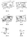
- FIG. 1Ashows a top view of a rigid plate in accordance with the present invention
- FIG. 1Bshows a bottom view of the rigid plate in accordance with the present invention
- FIG. 2Ashows a top view of a power module with which the present invention may be implemented
- FIG. 2Bshows a bottom view of the power module with which the present invention may be implemented
- FIG. 3Ashows a top view of a spring clip in accordance with the present invention
- FIG. 3Bshows a bottom view of the spring clip in accordance with the present invention
- FIG. 4Ashows an exploded perspective, top view of the assembly of the rigid plate, power module, and spring clip
- FIG. 4Bshows an exploded perspective, bottom view of the assembly of the rigid plate, power module, and spring clip.
- the present inventionprovides a method for designing power modules with rigid plates and spring clips to improve air cooling and achieve high useful power output.
- the inventiondoes not require changes in circuit layout and does not require any mechanical fasteners other than the clip between the power supply and the rigid plate.
- the inventionalso allows an end user to utilize a heat sink or a cold plate.
- FIGS. 1A and 1Bshow top and bottom views, respectively, of a rigid plate in accordance with the present invention.
- the rigid plate 100can be made of metal, plastic, ceramic, composite with high thermally conductive media such as graphite, or a mixture thereof.
- the plateis thermally conductive and may be electrically insulated.
- the surface of the plate facing the power module, shown in FIG. 1Bmay have contours that match the “skyline” of the power module components and create thermal paths to ambient from the power components, such as Field-Effect Transistors (FET), ferrite cores, copper traces on the printed circuit board (PCB), PCB sub-assembly, the base of a terminal pin, etc.
- the footprint of the rigid platemay be larger or smaller than the footprint of the matched power module
- the plate surface facing away from the power module, shown in FIG. 1Amay be flat and have mounting holes 101 , 102 (either through or blind) for mounting a heat sink or cold plate.
- the rigid plate 100may also also incorporate one or more heat sink feature, like parallel fins 114 or pin fins 116 . There may be positions 111 , 112 on the rigid plate for spring clips to anchor, but such attachment does not interfere with any heat sink or cold plate due to the recessed anchor points.
- the rigid plate 100has several pedestals 121 , 122 , 123 , 124 , and 125 facing downward that provide flush contact between the rigid plate and the power components, terminal pin bases and copper traces on the module.
- thermal interface materialsmay be utilized to enhance the thermal conductivity from the components on the module to the rigid plate.
- FIGS. 2A and 2Bshow top and bottom views, respectively, of a power module with which the present invention may be implemented.
- the power module itself 200is built on a Printed Circuit Board (PCB) 201 that is sufficiently thick to minimize board warping or relaxation during reflow soldering processes.
- PCBPrinted Circuit Board
- the modulecan be an existing design, treated as a sub-assembly, with the rigid plate and spring clip added to enhance air cooling without modifying the circuit layout.
- the PCB 201employs one or more magnetic devices 210 , 211 such as transformers, that in this case are core-on-board. In the present invention, there is insulation spacing, between the circuits having devices 210 and 211 .
- the rigid platemay attach the large and flat surface of the core-on-board devices without breaking out the isolation requirement.
- the power module 200also has a high-profile device 220 , such as an inductor, with a surface that is large and flat enough to be attached by the rigid plate 100 .
- the module 200may have one or more spots for the clip to anchor.
- the anchor spotscan be a portion of the module's PCB (with or without cutout), a Surface-Mount Technology (SMT) mechanical device, or a mechanical device through a cutout on the PCB.
- the power module 200has at least one power component to which the rigid plate 100 directly attaches. There may not necessarily be a power component to which the spring clip directly attaches, but the thermal path created by the clip provides an additional cooling effect (described below).
- FIGS. 3A and 3Bshow top and bottom views, respectively, of a spring clip in accordance with the present invention.
- the spring clip 300can be made of metal, plastic, composite with high thermally conductive materials such as graphite, or a mixture thereof.
- the spring clipis thermally conductive and may be electrically insulated. The electrical insulation may be powder coating or other interface material known in the art.
- the surface of the clip facing the power module, as shown in FIG. 3Amay have contours 301 , 302 to match the “skyline” of the module components.
- the clipmay also have a flat surface that contacts flush with either the power components or the rigid plate. The clip may create thermal paths to ambient from the power components just as the rigid plate does.
- the clip 300may have reinforcement (e.g., folding, bending or stamping) on at least one section to prevent the contact surface(s) facing the power module from bending or twisting, which would decrease the contact area.
- reinforcemente.g., folding, bending or stamping
- the spring clipmay have a non-uniform width 302 and may have one or more anchor tips 311 and 312 .
- the anchor tipsmay attach to the rigid plate or specific spots on the power module. Additionally, the spring clip does not necessarily have to anchor the rigid plate along a single cross-sectional plane.
- FIGS. 4A and 4Bshow exploded perspective views of the assembly of the rigid plate, power module, and spring clip.
- FIG. 4Ashows the top view perspective
- FIG. 4Bshows the bottom view perspective.
- the spring clip 300surrounds the bottom side of the power module 200 and a portion of each long side of the module.
- the clipprovides 300 a retaining force to hold the rigid plate 100 tight onto the module's notches on the top side and fits into the notches 111 , 112 on each long side of the rigid plate to maintain lateral position.
- Thermal interface materialsmay be filled between the rigid plate 100 and the power module 200 .
- the bottom of the clip 300contacts flush with at least one power component 230 of the pin side of the module 200 , and there is a cutout on the clip that keeps it away from high-profile components 240 , as depicted in FIG. 4B .
- Thermal interface materialis between the spring clip 300 and the power components 230 .
- the clipspans wider than the width of the module to avoid interfering with the module's PCB. Due to notches 111 , 112 , the vertical position of the clip tips does not exceed the top level of the rigid plate, so as not to interfere with the heat sink or cold plate mounting.
- the thermal interface materialscan be rigid, flexible, phase-changeable, paste-like, or any other type of suitable thermal interface material known in the art.
- the materialmay be filled and minimizes the thermal contact resistance between the power module and the rigid plate, and between the power module and the spring clip if necessary.
- the thermal interface materialmay also provide electrical insulation if neither the rigid plate 100 nor spring clip 300 have electrically insulated coatings or properties.
- the thermal interface materialmay also provide electrical isolation between the primary and secondary side of the power train.
- the thermal interface materialcan be tacky to allow for better attachment of the rigid plate 100 and spring clip 300 onto the power module 200 .
- the materialmay be thick enough to eliminate air voids when assembling the rigid plate 100 and spring clip 200 .
- the thermal interface materialmay be pre-installed on either the rigid plate 100 or the spring clip 200 , or it may be installed when the rigid plate, spring clip and power module are assembled.
- the useful power output of the power module 200is limited by the hottest power components.
- the paths to ambient provided by the rigid plate and spring clipfacilitate an averaging function that reduces the operating temperature of the hottest components. This averaging function allows the power module to operate at a power output level that would normally exceed the operating temperature limit of the hottest component.
Landscapes
- Engineering & Computer Science (AREA)
- Physics & Mathematics (AREA)
- Condensed Matter Physics & Semiconductors (AREA)
- General Physics & Mathematics (AREA)
- Computer Hardware Design (AREA)
- Microelectronics & Electronic Packaging (AREA)
- Power Engineering (AREA)
- Chemical & Material Sciences (AREA)
- Materials Engineering (AREA)
- Cooling Or The Like Of Electrical Apparatus (AREA)
Abstract
Description
Claims (16)
Priority Applications (1)
| Application Number | Priority Date | Filing Date | Title |
|---|---|---|---|
| US11/366,877US7450387B2 (en) | 2006-03-02 | 2006-03-02 | System for cooling electronic components |
Applications Claiming Priority (1)
| Application Number | Priority Date | Filing Date | Title |
|---|---|---|---|
| US11/366,877US7450387B2 (en) | 2006-03-02 | 2006-03-02 | System for cooling electronic components |
Publications (2)
| Publication Number | Publication Date |
|---|---|
| US20070206361A1 US20070206361A1 (en) | 2007-09-06 |
| US7450387B2true US7450387B2 (en) | 2008-11-11 |
Family
ID=38471264
Family Applications (1)
| Application Number | Title | Priority Date | Filing Date |
|---|---|---|---|
| US11/366,877ActiveUS7450387B2 (en) | 2006-03-02 | 2006-03-02 | System for cooling electronic components |
Country Status (1)
| Country | Link |
|---|---|
| US (1) | US7450387B2 (en) |
Cited By (23)
| Publication number | Priority date | Publication date | Assignee | Title |
|---|---|---|---|---|
| US20090067134A1 (en)* | 2007-09-10 | 2009-03-12 | Kabushiki Kaisha Toshiba | Electronic device |
| US20090103267A1 (en)* | 2007-10-17 | 2009-04-23 | Andrew Dean Wieland | Electronic assembly and method for making the electronic assembly |
| US20090284931A1 (en)* | 2008-05-15 | 2009-11-19 | International Business Machines Corporation | Nested fin integral heat sink assembly for multiple high power electonic circuit board modules |
| US20100079133A1 (en)* | 2008-09-29 | 2010-04-01 | Hirotaka Kadoshima | Heat sink mounting structure and electronic apparatus |
| US7733659B2 (en)* | 2006-08-18 | 2010-06-08 | Delphi Technologies, Inc. | Lightweight audio system for automotive applications and method |
| US20100296239A1 (en)* | 2008-05-21 | 2010-11-25 | Monem H Alyaser | Thermal interposer liquid cooling system |
| US20110222246A1 (en)* | 2010-03-11 | 2011-09-15 | Delta Electronics, Inc. | Heat-dissipating module and electronic device using same |
| DE102010035169A1 (en)* | 2010-08-23 | 2012-02-23 | Marquardt Verwaltungs-Gmbh | Control device i.e. electrical switch, for e.g. rechargeable battery driller, has heat generating component arranged in opening such that direct heat conducting connection of heat generating component to cooling body is enabled |
| US20120250260A1 (en)* | 2011-03-29 | 2012-10-04 | Eldon Technology Limited | Media content device with customized panel |
| US20140070387A1 (en)* | 2012-09-11 | 2014-03-13 | Lsis Co., Ltd. | Coupling assembly of power semiconductor device and pcb and method for manufacturing the same |
| US8760886B2 (en) | 2006-08-18 | 2014-06-24 | Delphi Technologies, Inc. | Lightweight audio system for automotive applications and method |
| US8902588B2 (en) | 2009-12-09 | 2014-12-02 | Thomson Licensing | Set-top box having microperforations |
| US20150342026A1 (en)* | 2012-12-17 | 2015-11-26 | Phoenix Contact Gmbh & Co. Kg | Electric assembly to be mounted on a top-hat rail |
| US9220185B2 (en) | 2010-05-19 | 2015-12-22 | Thomson Licensing | Set-top box having dissipating thermal loads |
| US9237685B2 (en) | 2006-08-18 | 2016-01-12 | Delphi Technologies, Inc. | Lightweight audio system for automotive applications and method |
| US9392317B2 (en) | 2011-03-09 | 2016-07-12 | Thomson Licensing | Set top box or server having snap-in heat sink and smart card reader |
| US9485884B2 (en) | 2011-07-14 | 2016-11-01 | Thomson Licensing | Set top box having snap-in heat sink and smart card reader with a hold down for retaining the heat sink |
| US9578783B2 (en) | 2010-02-25 | 2017-02-21 | Thomson Licensing | Miniature multilayer radiative cooling case wtih hidden quick release snaps |
| US9961758B1 (en) | 2016-10-10 | 2018-05-01 | Nidec Motor Corporation | Packaging a printed circuit board having a plurality of semiconductors in an inverter |
| US10433458B1 (en) | 2018-05-08 | 2019-10-01 | Hewlett Packard Enterprise Development Lp | Conducting plastic cold plates |
| US10856446B2 (en)* | 2018-02-08 | 2020-12-01 | Juniper Networks, Inc. | Cooling for slot mounted electrical modules |
| US11547018B2 (en)* | 2019-07-09 | 2023-01-03 | Kioxia Corporation | Semiconductor storage device |
| US20230033193A1 (en)* | 2021-07-28 | 2023-02-02 | Team Group Inc. | Water-cooling device for solid-state disk |
Families Citing this family (5)
| Publication number | Priority date | Publication date | Assignee | Title |
|---|---|---|---|---|
| US20070177356A1 (en)* | 2006-02-01 | 2007-08-02 | Jeffrey Panek | Three-dimensional cold plate and method of manufacturing same |
| CN102065662A (en)* | 2011-01-25 | 2011-05-18 | 无锡风光新能源科技有限公司 | Reverse type accurate positioning mechanism of semiconductor transistor |
| FR3002410B1 (en)* | 2013-02-20 | 2016-06-03 | Bull Sas | ELECTRONIC CARD COMPRISING A LIQUID COOLING SYSTEM |
| US11134591B2 (en)* | 2019-12-20 | 2021-09-28 | Astec International Limited | Circuit board assemblies for electronic devices |
| CN115379709A (en)* | 2021-05-18 | 2022-11-22 | 华为技术有限公司 | Heat dissipation device and vehicle-mounted module |
Citations (31)
| Publication number | Priority date | Publication date | Assignee | Title |
|---|---|---|---|---|
| US3268772A (en)* | 1963-03-26 | 1966-08-23 | North American Aviation Inc | Packaged electronic equipment |
| US3579821A (en)* | 1969-08-21 | 1971-05-25 | Us Navy | Method of making conformal blocks for evaporatively cooling circuit assemblies |
| US4029999A (en)* | 1975-04-10 | 1977-06-14 | Ibm Corporation | Thermally conducting elastomeric device |
| US4481525A (en)* | 1982-08-12 | 1984-11-06 | Anthony D. Calabro | Heat dissipator for integrated circuit chips |
| US4563725A (en)* | 1983-01-06 | 1986-01-07 | Welwyn Electronics Limited | Electrical assembly |
| US4635356A (en)* | 1984-12-28 | 1987-01-13 | Kabushiki Kaisha Toshiba | Method of manufacturing a circuit module |
| US4768286A (en)* | 1986-10-01 | 1988-09-06 | Eastman Christensen Co. | Printed circuit packaging for high vibration and temperature environments |
| US4878108A (en)* | 1987-06-15 | 1989-10-31 | International Business Machines Corporation | Heat dissipation package for integrated circuits |
| US5054193A (en)* | 1989-08-28 | 1991-10-08 | Hewlett-Packard Company | Printed circuit board fixture and a method of assembling a printed circuit board |
| US5208733A (en)* | 1990-11-09 | 1993-05-04 | Merlin Gerin | Enclosure and printed circuit card with heat sink |
| US5237485A (en)* | 1985-04-26 | 1993-08-17 | Sgs Microelettronica S.P.A. | Apparatus and method for improved thermal coupling of a semiconductor package to a cooling plate and increased electrical coupling of package leads on more than one side of the package to a circuit board |
| US5285350A (en)* | 1992-08-28 | 1994-02-08 | Aavid Engineering, Inc. | Heat sink plate for multiple semi-conductors |
| US5353191A (en)* | 1993-03-08 | 1994-10-04 | The Whitaker Corporation | Combination heat sink and housing for flexible electrical connector used in an electrical or electronic assembly |
| US5373418A (en)* | 1990-03-28 | 1994-12-13 | Mitsubishi Denki Kabushiki Kaisha | Electrical device for mounting electrical components with enhanced thermal radiating properties |
| US5926369A (en)* | 1998-01-22 | 1999-07-20 | International Business Machines Corporation | Vertically integrated multi-chip circuit package with heat-sink support |
| US6034874A (en)* | 1998-05-27 | 2000-03-07 | Alps Electric Co., Ltd. | Electronic device with heat radiating member |
| US6035524A (en)* | 1995-02-21 | 2000-03-14 | Thomson-Csf | Method for fabricating an electronics board with thermal-conduction cooling |
| US6093249A (en)* | 1995-02-22 | 2000-07-25 | Transition Automation, Inc. | Board matched nested support fixture |
| US6130821A (en)* | 1998-12-03 | 2000-10-10 | Motorola, Inc. | Multi-chip assembly having a heat sink and method thereof |
| US6205023B1 (en)* | 1996-11-22 | 2001-03-20 | Nec Corporation | Cooling arrangement comprising for a heat source a heat sink movable on an external sink |
| US6219236B1 (en)* | 1997-10-20 | 2001-04-17 | Fujitsu, Ltd. | Cooling system for multichip module |
| US6233150B1 (en)* | 1998-12-28 | 2001-05-15 | Foxconn Precision Components Co., Ltd. | Memory module assembly |
| US6625022B2 (en)* | 2000-09-29 | 2003-09-23 | Intel Corporation | Direct heatpipe attachment to die using center point loading |
| US6643135B2 (en) | 2001-03-28 | 2003-11-04 | Densei-Lambda Kabushiki Kaisha | On board mounting electronic apparatus and on board mounting electric power supply |
| US6657866B2 (en)* | 2002-03-15 | 2003-12-02 | Robert C. Morelock | Electronics assembly with improved heatsink configuration |
| US6687126B2 (en)* | 2001-04-30 | 2004-02-03 | Hewlett-Packard Development Company, L.P. | Cooling plate arrangement for electronic components |
| US20040042179A1 (en)* | 2002-08-27 | 2004-03-04 | Murphy Patrick Kevin | PCB heatsink |
| US6724631B2 (en) | 2002-04-22 | 2004-04-20 | Delta Electronics Inc. | Power converter package with enhanced thermal management |
| US20040136161A1 (en)* | 2003-01-10 | 2004-07-15 | Harold Miyamura | Heat sink attachment |
| JP2004336929A (en)* | 2003-05-09 | 2004-11-25 | Yaskawa Electric Corp | Power converter |
| US20070133176A1 (en)* | 2005-12-08 | 2007-06-14 | Ruei-An Lo | Heat dissipating element for a memory |
- 2006
- 2006-03-02USUS11/366,877patent/US7450387B2/enactiveActive
Patent Citations (32)
| Publication number | Priority date | Publication date | Assignee | Title |
|---|---|---|---|---|
| US3268772A (en)* | 1963-03-26 | 1966-08-23 | North American Aviation Inc | Packaged electronic equipment |
| US3579821A (en)* | 1969-08-21 | 1971-05-25 | Us Navy | Method of making conformal blocks for evaporatively cooling circuit assemblies |
| US4029999A (en)* | 1975-04-10 | 1977-06-14 | Ibm Corporation | Thermally conducting elastomeric device |
| US4481525A (en)* | 1982-08-12 | 1984-11-06 | Anthony D. Calabro | Heat dissipator for integrated circuit chips |
| US4563725A (en)* | 1983-01-06 | 1986-01-07 | Welwyn Electronics Limited | Electrical assembly |
| US4635356A (en)* | 1984-12-28 | 1987-01-13 | Kabushiki Kaisha Toshiba | Method of manufacturing a circuit module |
| US5237485A (en)* | 1985-04-26 | 1993-08-17 | Sgs Microelettronica S.P.A. | Apparatus and method for improved thermal coupling of a semiconductor package to a cooling plate and increased electrical coupling of package leads on more than one side of the package to a circuit board |
| US4768286A (en)* | 1986-10-01 | 1988-09-06 | Eastman Christensen Co. | Printed circuit packaging for high vibration and temperature environments |
| US4878108A (en)* | 1987-06-15 | 1989-10-31 | International Business Machines Corporation | Heat dissipation package for integrated circuits |
| US5054193A (en)* | 1989-08-28 | 1991-10-08 | Hewlett-Packard Company | Printed circuit board fixture and a method of assembling a printed circuit board |
| US5373418A (en)* | 1990-03-28 | 1994-12-13 | Mitsubishi Denki Kabushiki Kaisha | Electrical device for mounting electrical components with enhanced thermal radiating properties |
| US5208733A (en)* | 1990-11-09 | 1993-05-04 | Merlin Gerin | Enclosure and printed circuit card with heat sink |
| US5285350A (en)* | 1992-08-28 | 1994-02-08 | Aavid Engineering, Inc. | Heat sink plate for multiple semi-conductors |
| US5353191A (en)* | 1993-03-08 | 1994-10-04 | The Whitaker Corporation | Combination heat sink and housing for flexible electrical connector used in an electrical or electronic assembly |
| US6035524A (en)* | 1995-02-21 | 2000-03-14 | Thomson-Csf | Method for fabricating an electronics board with thermal-conduction cooling |
| US6093249A (en)* | 1995-02-22 | 2000-07-25 | Transition Automation, Inc. | Board matched nested support fixture |
| US6205023B1 (en)* | 1996-11-22 | 2001-03-20 | Nec Corporation | Cooling arrangement comprising for a heat source a heat sink movable on an external sink |
| US6219236B1 (en)* | 1997-10-20 | 2001-04-17 | Fujitsu, Ltd. | Cooling system for multichip module |
| US5926369A (en)* | 1998-01-22 | 1999-07-20 | International Business Machines Corporation | Vertically integrated multi-chip circuit package with heat-sink support |
| US6034874A (en)* | 1998-05-27 | 2000-03-07 | Alps Electric Co., Ltd. | Electronic device with heat radiating member |
| US6130821A (en)* | 1998-12-03 | 2000-10-10 | Motorola, Inc. | Multi-chip assembly having a heat sink and method thereof |
| US6233150B1 (en)* | 1998-12-28 | 2001-05-15 | Foxconn Precision Components Co., Ltd. | Memory module assembly |
| US6625022B2 (en)* | 2000-09-29 | 2003-09-23 | Intel Corporation | Direct heatpipe attachment to die using center point loading |
| US6643135B2 (en) | 2001-03-28 | 2003-11-04 | Densei-Lambda Kabushiki Kaisha | On board mounting electronic apparatus and on board mounting electric power supply |
| US6687126B2 (en)* | 2001-04-30 | 2004-02-03 | Hewlett-Packard Development Company, L.P. | Cooling plate arrangement for electronic components |
| US6657866B2 (en)* | 2002-03-15 | 2003-12-02 | Robert C. Morelock | Electronics assembly with improved heatsink configuration |
| US6724631B2 (en) | 2002-04-22 | 2004-04-20 | Delta Electronics Inc. | Power converter package with enhanced thermal management |
| US20040042179A1 (en)* | 2002-08-27 | 2004-03-04 | Murphy Patrick Kevin | PCB heatsink |
| US20040136161A1 (en)* | 2003-01-10 | 2004-07-15 | Harold Miyamura | Heat sink attachment |
| US6992893B2 (en)* | 2003-01-10 | 2006-01-31 | Hewlett-Packard Development Company, L.P. | Heat sink attachment |
| JP2004336929A (en)* | 2003-05-09 | 2004-11-25 | Yaskawa Electric Corp | Power converter |
| US20070133176A1 (en)* | 2005-12-08 | 2007-06-14 | Ruei-An Lo | Heat dissipating element for a memory |
Non-Patent Citations (1)
| Title |
|---|
| Theral Management Products, Chomerics Cat. No. 5509, Oct. 1999, Parker Hannifin Corp., p. 8.* |
Cited By (55)
| Publication number | Priority date | Publication date | Assignee | Title |
|---|---|---|---|---|
| US8599568B2 (en) | 2006-08-18 | 2013-12-03 | Delphi Technologies, Inc. | Lightweight audio system for automotive applications and method |
| US8593821B2 (en) | 2006-08-18 | 2013-11-26 | Delphi Technologies, Inc. | Lightweight audio system for automotive applications and method |
| US8830687B2 (en) | 2006-08-18 | 2014-09-09 | Delphi Technologies, Inc. | Lightweight audio system for automotive applications and method |
| US9237685B2 (en) | 2006-08-18 | 2016-01-12 | Delphi Technologies, Inc. | Lightweight audio system for automotive applications and method |
| US7733659B2 (en)* | 2006-08-18 | 2010-06-08 | Delphi Technologies, Inc. | Lightweight audio system for automotive applications and method |
| US20100202623A1 (en)* | 2006-08-18 | 2010-08-12 | Snider Chris R | Lightweight audio system for automotive applications and method |
| US9237683B2 (en) | 2006-08-18 | 2016-01-12 | Delphi Technologies, Inc. | Lightweight audio system for automotive applications and method |
| US8749988B2 (en) | 2006-08-18 | 2014-06-10 | Delphi Technologies, Inc. | Lightweight audio system for automotive applications and method |
| US9173332B2 (en) | 2006-08-18 | 2015-10-27 | Delphi Technologies, Inc. | Lightweight audio system for automotive applications and method |
| US8035976B2 (en) | 2006-08-18 | 2011-10-11 | Delphi Technologies, Inc. | Lightweight audio system for automotive applications and method |
| US8087165B2 (en) | 2006-08-18 | 2012-01-03 | Delphi Technologies, Inc. | Lightweight audio system for automotive applications and method |
| US9119288B2 (en) | 2006-08-18 | 2015-08-25 | Delphi Technologies, Inc. | Lightweight audio system for automotive applications and method |
| US8731862B2 (en) | 2006-08-18 | 2014-05-20 | Delphi Technologies, Inc. | Lightweight audio system for automotive applications and method |
| US9013881B2 (en) | 2006-08-18 | 2015-04-21 | Delphi Technologies, Inc. | Lightweight audio system for automotive applications and method |
| US8724335B2 (en) | 2006-08-18 | 2014-05-13 | Delphi Technologies, Inc. | Lightweight audio system for automotive applications and method |
| US8284559B2 (en) | 2006-08-18 | 2012-10-09 | Delphi Technologies, Inc. | Lightweight audio system for automotive applications and method |
| US8625293B2 (en) | 2006-08-18 | 2014-01-07 | Delphi Technologies, Inc. | Lightweight audio system for automotive applications and method |
| US8493739B2 (en) | 2006-08-18 | 2013-07-23 | Delphi Technologies, Inc. | Lightweight audio system for automotive applications and method |
| US8498126B2 (en) | 2006-08-18 | 2013-07-30 | Delphi Technologies, Inc. | Lightweight audio system for automotive applications and method |
| US8570757B2 (en) | 2006-08-18 | 2013-10-29 | Delphi Technologies, Inc. | Lightweight audio system for automotive applications and method |
| US8988884B2 (en) | 2006-08-18 | 2015-03-24 | Delphi Technologies, Inc | Lightweight audio system for automotive applications and method |
| US8760886B2 (en) | 2006-08-18 | 2014-06-24 | Delphi Technologies, Inc. | Lightweight audio system for automotive applications and method |
| US8477509B2 (en) | 2006-08-18 | 2013-07-02 | Delphi Technologies, Inc. | Lightweight audio system for automotive applications and method |
| US8625292B2 (en) | 2006-08-18 | 2014-01-07 | Delphi Technologies, Inc. | Lightweight audio system for automotive applications and method |
| US8982561B2 (en) | 2006-08-18 | 2015-03-17 | Delphi Technologies, Inc. | Lightweight audio system for automotive applications and method |
| US8947860B2 (en) | 2006-08-18 | 2015-02-03 | Delphi Technologies, Inc. | Lightweight audio system for automotive applications and method |
| US20090067134A1 (en)* | 2007-09-10 | 2009-03-12 | Kabushiki Kaisha Toshiba | Electronic device |
| US7864535B2 (en)* | 2007-09-10 | 2011-01-04 | Kabushiki Kaisha Toshiba | Electronic device |
| US20090103267A1 (en)* | 2007-10-17 | 2009-04-23 | Andrew Dean Wieland | Electronic assembly and method for making the electronic assembly |
| US20090284931A1 (en)* | 2008-05-15 | 2009-11-19 | International Business Machines Corporation | Nested fin integral heat sink assembly for multiple high power electonic circuit board modules |
| US8274787B2 (en)* | 2008-05-21 | 2012-09-25 | Asetek A/S | Thermal interposer liquid cooling system |
| US20100296239A1 (en)* | 2008-05-21 | 2010-11-25 | Monem H Alyaser | Thermal interposer liquid cooling system |
| US8755179B2 (en) | 2008-05-21 | 2014-06-17 | Asetek A/S | Thermal interposer liquid cooling system |
| US20100079133A1 (en)* | 2008-09-29 | 2010-04-01 | Hirotaka Kadoshima | Heat sink mounting structure and electronic apparatus |
| US8902588B2 (en) | 2009-12-09 | 2014-12-02 | Thomson Licensing | Set-top box having microperforations |
| US9578783B2 (en) | 2010-02-25 | 2017-02-21 | Thomson Licensing | Miniature multilayer radiative cooling case wtih hidden quick release snaps |
| US20110222246A1 (en)* | 2010-03-11 | 2011-09-15 | Delta Electronics, Inc. | Heat-dissipating module and electronic device using same |
| US8462509B2 (en)* | 2010-03-11 | 2013-06-11 | Delta Electronics, Inc. | Heat-dissipating module and electronic device using same |
| US9220185B2 (en) | 2010-05-19 | 2015-12-22 | Thomson Licensing | Set-top box having dissipating thermal loads |
| DE102010035169A1 (en)* | 2010-08-23 | 2012-02-23 | Marquardt Verwaltungs-Gmbh | Control device i.e. electrical switch, for e.g. rechargeable battery driller, has heat generating component arranged in opening such that direct heat conducting connection of heat generating component to cooling body is enabled |
| US9392317B2 (en) | 2011-03-09 | 2016-07-12 | Thomson Licensing | Set top box or server having snap-in heat sink and smart card reader |
| US9317079B2 (en)* | 2011-03-29 | 2016-04-19 | Echostar Uk Holdings Limited | Media content device with customized panel |
| US20120250260A1 (en)* | 2011-03-29 | 2012-10-04 | Eldon Technology Limited | Media content device with customized panel |
| US9485884B2 (en) | 2011-07-14 | 2016-11-01 | Thomson Licensing | Set top box having snap-in heat sink and smart card reader with a hold down for retaining the heat sink |
| US20140070387A1 (en)* | 2012-09-11 | 2014-03-13 | Lsis Co., Ltd. | Coupling assembly of power semiconductor device and pcb and method for manufacturing the same |
| US9165856B2 (en)* | 2012-09-11 | 2015-10-20 | Lsis Co., Ltd. | Coupling assembly of power semiconductor device and PCB and method for manufacturing the same |
| CN103687303B (en)* | 2012-09-11 | 2017-01-11 | Ls产电株式会社 | Coupling assembly of power semiconductor device and PCB and method for manufacturing the same |
| CN103687303A (en)* | 2012-09-11 | 2014-03-26 | Ls产电株式会社 | Coupling assembly of power semiconductor device and PCB and method for manufacturing the same |
| US20150342026A1 (en)* | 2012-12-17 | 2015-11-26 | Phoenix Contact Gmbh & Co. Kg | Electric assembly to be mounted on a top-hat rail |
| US10104762B2 (en)* | 2012-12-17 | 2018-10-16 | Phoenix Contact Gmbh & Co. Kg | Electric assembly to be mounted on a top-hat rail |
| US9961758B1 (en) | 2016-10-10 | 2018-05-01 | Nidec Motor Corporation | Packaging a printed circuit board having a plurality of semiconductors in an inverter |
| US10856446B2 (en)* | 2018-02-08 | 2020-12-01 | Juniper Networks, Inc. | Cooling for slot mounted electrical modules |
| US10433458B1 (en) | 2018-05-08 | 2019-10-01 | Hewlett Packard Enterprise Development Lp | Conducting plastic cold plates |
| US11547018B2 (en)* | 2019-07-09 | 2023-01-03 | Kioxia Corporation | Semiconductor storage device |
| US20230033193A1 (en)* | 2021-07-28 | 2023-02-02 | Team Group Inc. | Water-cooling device for solid-state disk |
Also Published As
| Publication number | Publication date |
|---|---|
| US20070206361A1 (en) | 2007-09-06 |
Similar Documents
| Publication | Publication Date | Title |
|---|---|---|
| US7450387B2 (en) | System for cooling electronic components | |
| KR100406461B1 (en) | Electronic circuit apparatus and method for assembling the same | |
| US6643135B2 (en) | On board mounting electronic apparatus and on board mounting electric power supply | |
| US20040037044A1 (en) | Heat sink for surface mounted power devices | |
| US20140035118A1 (en) | Semiconductor Module Arrangement and Method for Producing and Operating a Semiconductor Module Arrangement | |
| WO2006132271A1 (en) | Surface illuminator | |
| WO2008122220A1 (en) | Shielding and heat-dissipating device | |
| US20140285972A1 (en) | Housing and power module having the same | |
| US20100246139A1 (en) | Semiconductor apparatus and heat conductive sheet | |
| RU2423803C2 (en) | Wiring board for electronic component | |
| US6449158B1 (en) | Method and apparatus for securing an electronic power device to a heat spreader | |
| KR20070092432A (en) | Printed Circuit Board with Metal Core | |
| JP2022022924A (en) | Printed circuit board with heat dissipation terminal and heat sink for heat dissipation | |
| CN214544075U (en) | Power conversion device | |
| US6351385B1 (en) | Heat sink for integrated circuit packages | |
| JP5068098B2 (en) | Heat dissipation device | |
| JP4165045B2 (en) | Electronics | |
| TW561813B (en) | Power module | |
| US7385285B2 (en) | Light assembly | |
| JP6652144B2 (en) | Electronic parts, manufacturing method of electronic parts, mechanical parts | |
| JPH11163564A (en) | Electronic device and method of manufacturing electronic device | |
| US20090213549A1 (en) | Heat sink assembly | |
| KR20030063178A (en) | Electrical device | |
| US20240096738A1 (en) | Power semiconductor component and method for producing a power semiconductor component | |
| US20090067130A1 (en) | Arrangement for heat dissipation |
Legal Events
| Date | Code | Title | Description |
|---|---|---|---|
| AS | Assignment | Owner name:TDK INNOVETA TECHNOLOGIES, INC., TEXAS Free format text:ASSIGNMENT OF ASSIGNORS INTEREST;ASSIGNORS:CHENG, SUN-WEN CYRUS;WILDRICK, CARL MILTON;REEL/FRAME:017560/0542;SIGNING DATES FROM 20060307 TO 20060309 | |
| STCF | Information on status: patent grant | Free format text:PATENTED CASE | |
| FPAY | Fee payment | Year of fee payment:4 | |
| AS | Assignment | Owner name:TDK INNOVETA INC., TEXAS Free format text:CORRECTIVE ASSIGNMENT TO CORRECT THE TO CORRECT THE ASSIGNEE NAME TO TDK INNOVETA INC. PREVIOUSLY RECORDED ON REEL 017560 FRAME 0542. ASSIGNOR(S) HEREBY CONFIRMS THE THE CORRECT NAME OF THE ASSIGNEE SHOULD BE TDK INNOVETA INC, NOT TDK INNOVETA TECHNOLOGIES, INC.;ASSIGNORS:CHENG, SUN-WEN CYRUS;WILDRICK, CARL MILTON;SIGNING DATES FROM 20060307 TO 20060309;REEL/FRAME:029818/0741 | |
| AS | Assignment | Owner name:DENSEI-LAMBDA K.K., JAPAN Free format text:ASSIGNMENT OF ASSIGNORS INTEREST;ASSIGNOR:TDK INNOVETA INC.;REEL/FRAME:029825/0116 Effective date:20080930 | |
| AS | Assignment | Owner name:TDK-LAMBDA CORPORATION, JAPAN Free format text:CHANGE OF NAME;ASSIGNOR:DENSEI-LAMBDA K.K.;REEL/FRAME:029835/0694 Effective date:20081001 | |
| FPAY | Fee payment | Year of fee payment:8 | |
| MAFP | Maintenance fee payment | Free format text:PAYMENT OF MAINTENANCE FEE, 12TH YEAR, LARGE ENTITY (ORIGINAL EVENT CODE: M1553); ENTITY STATUS OF PATENT OWNER: LARGE ENTITY Year of fee payment:12 |