US7450382B1 - Apparatus for enclosing electronic components - Google Patents
Apparatus for enclosing electronic componentsDownload PDFInfo
- Publication number
- US7450382B1 US7450382B1US11/748,711US74871107AUS7450382B1US 7450382 B1US7450382 B1US 7450382B1US 74871107 AUS74871107 AUS 74871107AUS 7450382 B1US7450382 B1US 7450382B1
- Authority
- US
- United States
- Prior art keywords
- chassis enclosure
- heat sink
- sink fins
- front wall
- support members
- Prior art date
- Legal status (The legal status is an assumption and is not a legal conclusion. Google has not performed a legal analysis and makes no representation as to the accuracy of the status listed.)
- Active
Links
Images


Classifications
- H—ELECTRICITY
- H05—ELECTRIC TECHNIQUES NOT OTHERWISE PROVIDED FOR
- H05K—PRINTED CIRCUITS; CASINGS OR CONSTRUCTIONAL DETAILS OF ELECTRIC APPARATUS; MANUFACTURE OF ASSEMBLAGES OF ELECTRICAL COMPONENTS
- H05K7/00—Constructional details common to different types of electric apparatus
- H05K7/20—Modifications to facilitate cooling, ventilating, or heating
- H05K7/20536—Modifications to facilitate cooling, ventilating, or heating for racks or cabinets of standardised dimensions, e.g. electronic racks for aircraft or telecommunication equipment
- H05K7/20545—Natural convection of gaseous coolant; Heat transfer by conduction from electronic boards
Definitions
- Environmentally protected housingsare used in a wide variety of applications, including containing and protecting electronic components of the type used for transferring signals over long distances.
- the telecommunications industrytransfers signals over optical fibers. If the signal is transferred over a long distance, the signal may be too weak by the time it reaches its destination to be useful. Consequently, electronic circuit cards are used to detect, clean up, and amplify a weak signal for retransmission through another length of fiber-optic cable. These electronic circuit cards are often deployed in environmentally protected housings located above and below ground.
- such an apparatuscomprises a chassis enclosure defining an internal chamber and comprising an upper portion and a lower portion.
- the upper portioncomprises a first front wall having a length dimension greater than a width dimension, and a first pair of opposing side walls that are each contiguous with the first front wall.
- the lower portioncomprises a second front wall having a length dimension less than the length dimension of the first front wall, and a second pair of opposing side walls that are each contiguous with the second front wall.
- a plurality of heat sink finsare on each of the first front wall and the first pair of opposing side walls.
- a plurality of heat sink finsare also on each of the second front wall and the second pair of opposing side walls.
- Each of the heat sink finsare configured to be substantially parallel to the length dimension of the first front wall and the second front wall, and extend continuously along each wall.
- the plurality of heat sink finshas an arcuate-like end view profile on each wall of the chassis enclosure.
- FIG. 1is an elevated perspective view of an apparatus for enclosing electronic components according to one embodiment of the invention
- FIG. 2Ais a side view of the apparatus shown in FIG. 1 ;
- FIG. 2Bis a front view of the apparatus shown in FIG. 1 ;
- FIG. 2Cis a top view of the apparatus shown in FIG. 1 ;
- FIG. 3is an exploded perspective view of an apparatus for enclosing electronic components according to another embodiment of the invention.
- FIG. 4is an elevated perspective view of the apparatus shown in FIG. 3 in an assembled form
- FIG. 5Ais a front view of the apparatus shown in FIG. 4 ;
- FIG. 5Bis a side view of the apparatus shown in FIG. 4 ;
- FIG. 5Cis a top view of the apparatus shown in FIG. 4 ;
- FIG. 6is an elevated perspective view of the apparatus of FIG. 4 shown with an optional shroud according to a further embodiment of the invention
- FIG. 7is a rear perspective view of the apparatus shown in FIG. 6 ;
- FIG. 8is an enlarged sectional view of the apparatus shown in FIG. 7 .
- FIG. 1is a perspective view of one embodiment of an apparatus 100 for enclosing electronic components used in a telecommunication system. Other views of apparatus 100 are shown in FIGS. 2A-2C .
- the apparatus 100has a chassis enclosure 110 with an internal chamber.
- the internal chamber of chassis enclosure 110is configured to hold various components of a telecommunication system, such as a wideband digital radio, a power amplifier, a radio frequency (RF) transport, a wideband digital transceiver, a power supply, or other electronic components.
- the enclosure 110is configured so that one or more telecommunication services can be provided therefrom, such as, for example, 800-A, 800-B, specialized mobile radio (SMR), 1900, 900, and 2100.
- SMRspecialized mobile radio
- the chassis enclosure 110has a length greater than a width thereof, and has a plurality of legs 114 that support apparatus 100 in an upright position.
- the legs 114also protect protruding connectors from damage during shipping or installation.
- the chassis enclosure 110can be made of any material having a suitable combination of thermal properties, corrosion resistance, and strength, such as a metallic material.
- the chassis enclosure 110can be made from welded sheet metal or cast metal. Suitable exemplary materials for chassis enclosure 110 include aluminum, magnesium, zinc, steel, or combinations thereof.
- a divided upper plate 116covers the top of chassis enclosure 110 and has a lifting attachment point 117 thereon, which provides the ability to use a hoist to position and handle enclosure 110 .
- a lower plate 118covers the bottom of chassis enclosure 110 and also has an attachment point 119 thereon useful in handling and assembly.
- a back cover 120is attached to the backside of chassis enclosure 110 .
- a series of duplexers or other non-heat generating electronicscan be attached to an inner surface of back cover 120 so that the duplexers or other electronics are disposed in the chamber of chassis enclosure 110 when back cover 120 is attached thereto.
- the back cover 120can be removably attached to chassis enclosure 110 by conventional fasteners such as bolts, clamps, latches, or other mechanical locking features.
- the back cover 120can be formed of cast metal or machined metal, such as aluminum, magnesium, zinc, steel, or combinations thereof.
- the chassis enclosure 110has an upper portion 122 including a first front wall 124 having a length dimension greater than a width dimension.
- a first pair of opposing side walls 126 , 128are each contiguous with the first front wall 124 .
- the first front wall 124 and first sides walls 126 , 128are movably attached to chassis enclosure 110 by a plurality of hinges 130 . This allows the first front and side walls to be easily opened and closed, thereby providing access to the internal chamber of chassis enclosure 110 .
- the chassis enclosure 110also has a lower portion 132 that includes a second front wall 134 having a length dimension less than the length dimension of the first front wall 124 .
- a second pair of opposing side walls 136 , 138are each contiguous with the second front wall 134 .
- the second front wall 134 and second sides walls 136 , 138are movably attached to chassis enclosure 110 by a plurality of hinges 140 that allow the second front and side walls to be opened and closed as desired.
- a plurality of heat sink fins 150are disposed on each of first front wall 124 and first side walls 126 , 128 .
- a plurality of heat sink fins 152are also disposed on each of second front wall 134 and second side walls 136 , 138 .
- Each of the finsare configured to be substantially parallel with respect to the length dimension of the first and second front walls, and can extend continuously along the length of each wall without a gap. The fins allow apparatus 100 to utilize natural convection cooling, with no fans or heat pipes.
- the plurality of heat sink fins 150 , 152have an arcuate-like end view profile on each wall such as shown in FIGS. 1 and 2C .
- fins that are closer to the hingesprotrude outwardly from each wall a shorter distance than the fins that are toward a middle portion of the wall.
- This configurationserves the purpose of maximizing the fin height of the central fins, which are required to dissipate the most heat, and shorten the fins on the edges that dissipate less heat.
- the substantially arcuate profile of the finsreduces the total cross-section and improves heat dissipation.
- the finscan be formed of a cast metal, an extruded metal, or a machined metal, such as aluminum, magnesium, zinc, steel, or combinations thereof.
- the finscan be attached to the walls of chassis enclosure 110 by welding, latching, bolting, or other means for mechanical clamping.
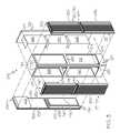
- FIG. 3is an exploded perspective view of another embodiment of an apparatus 200 for enclosing electronic components used in a telecommunication system. Additional views of apparatus 200 in an assembled form are shown in FIGS. 4 and 5 A- 5 C.
- apparatus 200has a chassis enclosure 210 having an open backside that communicates with an internal chamber 212 .
- the chassis enclosure 210has a length greater than a width thereof.
- the chassis enclosure 210has a plurality of elongated legs 214 that are contiguous with a plurality of lateral support members 215 , a plurality of base support members 216 , and a plurality of top support members 217 .
- the lateral support members 215are interposed between the base support members 216 and the top support members 217 .
- a top plate 218is attached to top support members 217 .
- the legs 214 , lateral support members 215 , base support members 216 , and top support members 217are configured to define a pair of openings into the chamber at each side of chassis enclosure 210 along the length thereof except for the backside.
- the chamberis open from the top plate 218 to the base support members 216 .
- the chassis enclosure 210can be made from welded sheet metal or cast metal, such as aluminum, magnesium, zinc, steel, or combinations thereof.
- An elongated mounting plate 220is configured to be removably attached to the backside of chassis enclosure 210 .
- a series of duplexers 222 , 224 , and 226can be attached to an inner surface 227 of mounting plate 220 so that the duplexers are disposed in chamber 212 when mounting plate 220 is attached to chassis enclosure 210 .
- the mounting plate 220can be removably attached to chassis enclosure 210 by conventional fasteners such as bolts, clamps, or latches.
- the mounting plate 220can be formed of cast metal or machined metal, such as aluminum, magnesium, zinc, steel, or combinations thereof.
- a plurality of rectangular upper panels 230are configured to be removably attached to legs 214 , lateral support members 215 , and top support members 217 in order to cover corresponding upper openings 219 of the pair of openings along each side.
- a plurality of rectangular lower panels 231are configured to be removably attached to elongated legs 214 , lateral support members 215 , and base support members 216 in order to cover corresponding lower openings 221 of the pair of openings along each side.
- the upper and lower panelscan be attached to the various portions of chassis enclosure 210 by conventional fasteners such as bolts, clamps or latches.
- An inner surface 232 of upper panels 230is configured to hold a linear power amplifier (LPA) 234 and has a power supply area 236 .
- An inner surface 233 of lower panels 231is configured to hold a printed circuit board (PCB) assembly 240 .
- the apparatus 200is capable of supporting up to three telecommunication bands, with separate access for each band. Clearance is also provided in apparatus 200 for each band to have its own power supply. In an alternative embodiment, separate access is provided for each band, but with the PCB assembly, LPA, and power supply mounted to a single heat sink to reduce the number of openings.
- custom LPA and duplexer designscan be employed to allow the size of apparatus 200 to be reduced.
- This embodimentalso allows for increased LPA cooling by sinking the LPA to the duplexer which is used as a heat sink.
- the apparatus 200utilizes natural convection cooling, with no fans or heat pipes. Accordingly, an outer surface 242 of each of upper panels 230 has a plurality of heat sink fins 250 thereon. Likewise, an outer surface 244 of each of lower panels 231 has a plurality of heat sink fins 252 thereon.
- the heat sink fins 250 , 252can be positioned to be substantially parallel with respect to a length dimension L of apparatus 200 such as shown in FIG. 5A .
- Each of heat sink fins 250 , 252can also extend continuously along each panel without a gap.
- the heat sink fins 250 , 252can be formed of a cast metal, an extruded metal, or a machined metal, such as aluminum, magnesium, zinc, steel, or combinations thereof.
- the heat sink finscan be attached to the upper and lower panels by welding, bolting, latching, or other means of mechanical clamping.
- the apparatus 200can be mounted on a pole inside or outside.
- the apparatus 200can also be mounted on a wall, a vault, or a strand such as a cable strand.
- an optional shroud 300can be placed around apparatus 200 to provide a solar shield.
- the shroud 300has elongated rectangular side panels 310 that cover heat sink fins 250 , 252 on apparatus 200 .
- the shroud 300also has a vented top cover 312 with a plurality of apertures 314 to provide for escape of exhaust air.
- the shroud 300can be formed of a sheet metal or machined metal, such as aluminum, magnesium, zinc, steel, or combinations thereof.
- a plurality of fans 320can be disposed in a compartment of shroud 300 below vented top cover 312 and over top plate 218 .
- the fansprovide assisted forced convection cooling for extreme environments.
- airis drawn up through openings between side panels 310 and heat sink fins 252 adjacent to base support members 216 to provide for increased cooling.
- the exhaust airexits through vented top cover 312 .
- the fansact to increase the air velocity over heat sink fins 250 , 252 by reducing the pressure at the top of the air column. The resulting increased volumetric air flow increases the amount of heat dissipation while still allowing the electronics to remain sealed within the enclosure.
Landscapes
- Engineering & Computer Science (AREA)
- Aviation & Aerospace Engineering (AREA)
- Physics & Mathematics (AREA)
- Thermal Sciences (AREA)
- Microelectronics & Electronic Packaging (AREA)
- Cooling Or The Like Of Electrical Apparatus (AREA)
- Casings For Electric Apparatus (AREA)
Abstract
Description
Claims (27)
Priority Applications (1)
| Application Number | Priority Date | Filing Date | Title |
|---|---|---|---|
| US11/748,711US7450382B1 (en) | 2007-05-15 | 2007-05-15 | Apparatus for enclosing electronic components |
Applications Claiming Priority (1)
| Application Number | Priority Date | Filing Date | Title |
|---|---|---|---|
| US11/748,711US7450382B1 (en) | 2007-05-15 | 2007-05-15 | Apparatus for enclosing electronic components |
Publications (2)
| Publication Number | Publication Date |
|---|---|
| US7450382B1true US7450382B1 (en) | 2008-11-11 |
| US20080285231A1 US20080285231A1 (en) | 2008-11-20 |
Family
ID=39940841
Family Applications (1)
| Application Number | Title | Priority Date | Filing Date |
|---|---|---|---|
| US11/748,711ActiveUS7450382B1 (en) | 2007-05-15 | 2007-05-15 | Apparatus for enclosing electronic components |
Country Status (1)
| Country | Link |
|---|---|
| US (1) | US7450382B1 (en) |
Cited By (34)
| Publication number | Priority date | Publication date | Assignee | Title |
|---|---|---|---|---|
| US20090101382A1 (en)* | 2007-10-17 | 2009-04-23 | Alcatel Lucent | Sealed expansion module |
| US20090231815A1 (en)* | 2008-03-12 | 2009-09-17 | Duk-Yong Kim | Enclosure device of wireless communication apparatus |
| US20090311463A1 (en)* | 2008-06-11 | 2009-12-17 | Adc Telecommunications, Inc. | Solar shields |
| US20090309467A1 (en)* | 2008-06-11 | 2009-12-17 | Adc Telecommunications, Inc. | Angled doors with continuous seal |
| US20090308655A1 (en)* | 2008-06-11 | 2009-12-17 | Adc Telecommunications, Inc. | Combination extruded and cast metal outdoor electronics enclosure |
| US20090310309A1 (en)* | 2008-06-11 | 2009-12-17 | Adc Telecommunications, Inc. | Systems and methods for thermal management |
| US20090311969A1 (en)* | 2008-06-11 | 2009-12-17 | Adc Telecommunications, Inc. | Communication modules |
| US20090310301A1 (en)* | 2008-06-11 | 2009-12-17 | Adc Telecommunications, Inc. | Systems and methods for venturi fan-assisted cooling |
| US20090307983A1 (en)* | 2008-06-11 | 2009-12-17 | Adc Telecommunications, Inc. | L-shaped door with three-surface seal for endplates |
| US20100044008A1 (en)* | 2008-08-20 | 2010-02-25 | Michael Drummy | Portable environmentally robust enclosure optimized for size, weight, and power dissipation |
| US20100085710A1 (en)* | 2008-10-02 | 2010-04-08 | Raytheon Company | Canister Housing |
| US20100116545A1 (en)* | 2008-11-10 | 2010-05-13 | Adc Telecommunications, Inc. | Weather resistant variable enclosure frame |
| USD619992S1 (en)* | 2007-03-27 | 2010-07-20 | Adc Telecommunications, Inc. | Chassis for electronic circuitry |
| USD621812S1 (en)* | 2007-03-27 | 2010-08-17 | Adc Telecommunications, Inc. | Chassis for electronic circuitry |
| US20100302728A1 (en)* | 2007-11-28 | 2010-12-02 | Voltwerk Electronics Gmbh | Chassis for inverter |
| US20100321896A1 (en)* | 2009-06-17 | 2010-12-23 | Yosuke Yamada | Electrical power component attached to chassis of an electrical power apparatus |
| USD651200S1 (en)* | 2010-01-26 | 2011-12-27 | Kyocera Corporation | Base station |
| US20120044633A1 (en)* | 2010-08-30 | 2012-02-23 | Hardcore Computer, Inc. | Extruded server case |
| US8214086B2 (en) | 2010-04-01 | 2012-07-03 | Adc Telecommunications, Inc. | Systems and methods for retractable fan cooling of electronic enclosures |
| US8797169B1 (en) | 2011-04-14 | 2014-08-05 | Adtran, Inc. | Systems and methods for sensing and indicating orientation of electrical equipment with passive cooling |
| US8823531B1 (en) | 2011-04-14 | 2014-09-02 | Adtran, Inc. | Systems and methods for sensing and indicating orientation of electrical equipment with active cooling |
| CN104066299A (en)* | 2013-03-20 | 2014-09-24 | 鸿富锦精密工业(深圳)有限公司 | cabinet |
| US8964401B2 (en) | 2011-10-14 | 2015-02-24 | Sunpower Corporation | Electrical insulator casing |
| US20150124407A1 (en)* | 2013-11-06 | 2015-05-07 | Hamilton Sundstrand Corporation | High-temperature environment electronic chassis |
| US20150169014A1 (en)* | 2011-11-30 | 2015-06-18 | Google, Inc. | Notebook metal hinge as heat sink element |
| CN104782139A (en)* | 2012-11-16 | 2015-07-15 | 株式会社Kmw | Small-sized base station device in mobile communication system |
| US20150305200A1 (en)* | 2014-04-17 | 2015-10-22 | Fujitsu Limited | Heat dissipation device, electronic device, and base station device |
| US20160231424A1 (en)* | 2015-02-10 | 2016-08-11 | Nen-Tsua Li | Laser distance measure |
| USD799651S1 (en)* | 2015-10-29 | 2017-10-10 | Stego-Holding Gmbh | Convector |
| CN108750340A (en)* | 2018-07-04 | 2018-11-06 | 马鞍山市思迪包装材料科技有限公司 | A kind of fin radiator specialized package transport case |
| US20190020713A1 (en)* | 2017-07-14 | 2019-01-17 | Amazon Technologies, Inc. | Antenna structures and isolation chambers of a multi-radio, multi-channel (mrmc) mesh network device |
| US10314193B2 (en)* | 2017-11-01 | 2019-06-04 | Hyundai Autron Co., Ltd. | Electronic control device |
| USD870723S1 (en)* | 2017-08-10 | 2019-12-24 | Arçelik Anonim Sirketi | Electronic information terminal |
| US10615514B2 (en) | 2017-07-14 | 2020-04-07 | Amazon Technologies, Inc. | Antenna structures of a multi-radio, multi-channel (MRMC) mesh network device |
Families Citing this family (7)
| Publication number | Priority date | Publication date | Assignee | Title |
|---|---|---|---|---|
| US20120134114A1 (en)* | 2010-07-22 | 2012-05-31 | Nick Kamenszky | Thermal management of environmentally-sealed electronics enclosure |
| CN103596297B (en)* | 2012-08-13 | 2017-04-12 | 华为技术有限公司 | Radio remote unit devices and assemblies thereof |
| TWM523267U (en)* | 2015-07-16 | 2016-06-01 | 鋐寶科技股份有限公司 | Electronic apparatus |
| USD835040S1 (en) | 2016-09-09 | 2018-12-04 | Corning Research & Development Corporation | 1×4 distribution point unit |
| US10775857B2 (en)* | 2018-05-07 | 2020-09-15 | Dell Products L.P. | Forced convection cooling system |
| CN218005217U (en) | 2019-02-06 | 2022-12-09 | 安德鲁无线系统有限公司 | Modular Filter/Duplexer System |
| US12425053B2 (en) | 2020-11-09 | 2025-09-23 | Outdoor Wireless Networks LLC | Wideband modular filter/duplexer system |
Citations (28)
| Publication number | Priority date | Publication date | Assignee | Title |
|---|---|---|---|---|
| US4656559A (en) | 1984-05-10 | 1987-04-07 | Ultima Electronics Ltd. | Holder and heat sink for electronic components |
| US4962445A (en)* | 1988-04-21 | 1990-10-09 | Societe Anonyme Dite: Alcatel Cit | Housing for submersible equipment |
| US5065278A (en)* | 1990-01-29 | 1991-11-12 | Power Guard | Cast housing encased CATV power supply unit |
| US5089935A (en) | 1990-02-28 | 1992-02-18 | Mitsubishi Denki Kabushiki Kaisha | Control device case |
| US5150278A (en) | 1991-04-16 | 1992-09-22 | J. E. Thomas Specialties Limited | Finned housing |
| US5267122A (en) | 1992-06-15 | 1993-11-30 | Alcatel Network Systems, Inc. | Optical network unit |
| US5842514A (en) | 1997-03-05 | 1998-12-01 | Northern Telecom Limited | Electronic unit |
| US6028769A (en)* | 1996-05-20 | 2000-02-22 | Adc Telecommunication, Inc. | Multiple integrated service unit for communication system |
| US6104611A (en) | 1995-10-05 | 2000-08-15 | Nortel Networks Corporation | Packaging system for thermally controlling the temperature of electronic equipment |
| US6118662A (en)* | 1999-11-05 | 2000-09-12 | Special Product Company | Enclosure for telecommunications equipment |
| US6396691B1 (en)* | 2000-04-17 | 2002-05-28 | Circa Telecom, Usa, Inc. | Thermal cover for T1/HDSL repeater case |
| USD462675S1 (en) | 2000-11-06 | 2002-09-10 | Adc Telecommunications, Inc. | Radiating repeater case |
| US6510223B2 (en) | 1997-11-06 | 2003-01-21 | Anacapa Technology, Inc. | Local loop telecommunication repeater housings employing thermal collection, transfer and distribution via solid thermal conduction |
| US6563050B2 (en) | 2000-11-06 | 2003-05-13 | Adc Telecommunications, Inc. | Cable head assembly |
| US6587339B1 (en) | 2002-03-29 | 2003-07-01 | Thornhurst Manufacturing, Inc. | Protective pot or container |
| US6603660B1 (en)* | 2002-08-12 | 2003-08-05 | Netrix Technologies, Inc. | Remote distribution frame |
| US6611426B2 (en)* | 2000-02-10 | 2003-08-26 | Special Products Company | Telecommunications enclosure with individual, separated card holders |
| US6628521B2 (en) | 2000-11-06 | 2003-09-30 | Adc Telecommunications, Inc. | Mechanical housing |
| US20040007348A1 (en)* | 2002-07-11 | 2004-01-15 | Stoller Harry R. | Systems and methods for weatherproof cabinets with variably cooled compartments |
| US6781830B2 (en) | 2002-11-05 | 2004-08-24 | Adc Dsl Systems, Inc. | Methods and systems of heat transfer for electronic enclosures |
| US6862180B2 (en) | 2002-05-24 | 2005-03-01 | Adc Dsl Systems, Inc. | Housings for circuit cards |
| US6865085B1 (en) | 2003-09-26 | 2005-03-08 | Adc Dsl Systems, Inc. | Heat dissipation for electronic enclosures |
| US6894907B2 (en) | 2001-07-31 | 2005-05-17 | Adc Telecommunications, Inc. | Clamping case |
| US6897377B2 (en) | 2001-07-31 | 2005-05-24 | Adc Telecommunications, Inc. | Clamping receptacle |
| US20060204397A1 (en)* | 2002-08-23 | 2006-09-14 | Nippon Metal Industry Co., Ltd. | Sn-zn lead-free solder alloy, and solder junction portion |
| US7118697B2 (en) | 2002-07-02 | 2006-10-10 | Adc Dsl Systems Inc. | Method of molding composite objects |
| US7245485B1 (en)* | 2004-11-15 | 2007-07-17 | Utstarcom, Inc. | Electronics cabinet with internal air-to-air heat exchanger |
| US7355848B1 (en)* | 2002-01-07 | 2008-04-08 | Wave7 Optics, Inc. | System and method for removing heat from a subscriber optical interface |
- 2007
- 2007-05-15USUS11/748,711patent/US7450382B1/enactiveActive
Patent Citations (31)
| Publication number | Priority date | Publication date | Assignee | Title |
|---|---|---|---|---|
| US4656559A (en) | 1984-05-10 | 1987-04-07 | Ultima Electronics Ltd. | Holder and heat sink for electronic components |
| US4962445A (en)* | 1988-04-21 | 1990-10-09 | Societe Anonyme Dite: Alcatel Cit | Housing for submersible equipment |
| US5065278A (en)* | 1990-01-29 | 1991-11-12 | Power Guard | Cast housing encased CATV power supply unit |
| US5089935A (en) | 1990-02-28 | 1992-02-18 | Mitsubishi Denki Kabushiki Kaisha | Control device case |
| US5150278A (en) | 1991-04-16 | 1992-09-22 | J. E. Thomas Specialties Limited | Finned housing |
| US5267122A (en) | 1992-06-15 | 1993-11-30 | Alcatel Network Systems, Inc. | Optical network unit |
| US6104611A (en) | 1995-10-05 | 2000-08-15 | Nortel Networks Corporation | Packaging system for thermally controlling the temperature of electronic equipment |
| US6028769A (en)* | 1996-05-20 | 2000-02-22 | Adc Telecommunication, Inc. | Multiple integrated service unit for communication system |
| US5842514A (en) | 1997-03-05 | 1998-12-01 | Northern Telecom Limited | Electronic unit |
| US6510223B2 (en) | 1997-11-06 | 2003-01-21 | Anacapa Technology, Inc. | Local loop telecommunication repeater housings employing thermal collection, transfer and distribution via solid thermal conduction |
| US6118662A (en)* | 1999-11-05 | 2000-09-12 | Special Product Company | Enclosure for telecommunications equipment |
| US6611426B2 (en)* | 2000-02-10 | 2003-08-26 | Special Products Company | Telecommunications enclosure with individual, separated card holders |
| US6396691B1 (en)* | 2000-04-17 | 2002-05-28 | Circa Telecom, Usa, Inc. | Thermal cover for T1/HDSL repeater case |
| US6563050B2 (en) | 2000-11-06 | 2003-05-13 | Adc Telecommunications, Inc. | Cable head assembly |
| USD462675S1 (en) | 2000-11-06 | 2002-09-10 | Adc Telecommunications, Inc. | Radiating repeater case |
| US6628521B2 (en) | 2000-11-06 | 2003-09-30 | Adc Telecommunications, Inc. | Mechanical housing |
| US7075789B2 (en) | 2000-11-06 | 2006-07-11 | Adc Telecommunications, Inc. | Mechanical housing |
| US6894907B2 (en) | 2001-07-31 | 2005-05-17 | Adc Telecommunications, Inc. | Clamping case |
| US6992249B2 (en) | 2001-07-31 | 2006-01-31 | Adc Telecommunications, Inc. | Clamping receptacle |
| US20050170681A1 (en) | 2001-07-31 | 2005-08-04 | Adc Telecommunications, Inc. | Clamping case |
| US6897377B2 (en) | 2001-07-31 | 2005-05-24 | Adc Telecommunications, Inc. | Clamping receptacle |
| US7355848B1 (en)* | 2002-01-07 | 2008-04-08 | Wave7 Optics, Inc. | System and method for removing heat from a subscriber optical interface |
| US6587339B1 (en) | 2002-03-29 | 2003-07-01 | Thornhurst Manufacturing, Inc. | Protective pot or container |
| US6862180B2 (en) | 2002-05-24 | 2005-03-01 | Adc Dsl Systems, Inc. | Housings for circuit cards |
| US7118697B2 (en) | 2002-07-02 | 2006-10-10 | Adc Dsl Systems Inc. | Method of molding composite objects |
| US20040007348A1 (en)* | 2002-07-11 | 2004-01-15 | Stoller Harry R. | Systems and methods for weatherproof cabinets with variably cooled compartments |
| US6603660B1 (en)* | 2002-08-12 | 2003-08-05 | Netrix Technologies, Inc. | Remote distribution frame |
| US20060204397A1 (en)* | 2002-08-23 | 2006-09-14 | Nippon Metal Industry Co., Ltd. | Sn-zn lead-free solder alloy, and solder junction portion |
| US6781830B2 (en) | 2002-11-05 | 2004-08-24 | Adc Dsl Systems, Inc. | Methods and systems of heat transfer for electronic enclosures |
| US6865085B1 (en) | 2003-09-26 | 2005-03-08 | Adc Dsl Systems, Inc. | Heat dissipation for electronic enclosures |
| US7245485B1 (en)* | 2004-11-15 | 2007-07-17 | Utstarcom, Inc. | Electronics cabinet with internal air-to-air heat exchanger |
Non-Patent Citations (1)
| Title |
|---|
| Fox et al., "Star-Structure Optical Local Networks", "British Telecommunications Technology Journal", Apr. 1989, pp. 76-88, vol. 7, No. 2, Publisher: Fulcrum. |
Cited By (60)
| Publication number | Priority date | Publication date | Assignee | Title |
|---|---|---|---|---|
| USD619992S1 (en)* | 2007-03-27 | 2010-07-20 | Adc Telecommunications, Inc. | Chassis for electronic circuitry |
| USD621812S1 (en)* | 2007-03-27 | 2010-08-17 | Adc Telecommunications, Inc. | Chassis for electronic circuitry |
| US20090101382A1 (en)* | 2007-10-17 | 2009-04-23 | Alcatel Lucent | Sealed expansion module |
| US8023271B2 (en)* | 2007-10-17 | 2011-09-20 | Alcatel Lucent | Sealed expansion module |
| US20100302728A1 (en)* | 2007-11-28 | 2010-12-02 | Voltwerk Electronics Gmbh | Chassis for inverter |
| US20090231815A1 (en)* | 2008-03-12 | 2009-09-17 | Duk-Yong Kim | Enclosure device of wireless communication apparatus |
| US8004844B2 (en)* | 2008-03-12 | 2011-08-23 | Kmw, Inc. | Enclosure device of wireless communication apparatus |
| US8148648B2 (en) | 2008-06-11 | 2012-04-03 | Adc Telecommunications, Inc. | Combination extruded and cast metal outdoor electronics enclosure |
| US20090309467A1 (en)* | 2008-06-11 | 2009-12-17 | Adc Telecommunications, Inc. | Angled doors with continuous seal |
| US20090307983A1 (en)* | 2008-06-11 | 2009-12-17 | Adc Telecommunications, Inc. | L-shaped door with three-surface seal for endplates |
| US8125785B2 (en)* | 2008-06-11 | 2012-02-28 | Adc Telecommunications, Inc. | Angled doors with continuous seal |
| US20090311463A1 (en)* | 2008-06-11 | 2009-12-17 | Adc Telecommunications, Inc. | Solar shields |
| US8254850B2 (en) | 2008-06-11 | 2012-08-28 | Adc Telecommunications, Inc. | Communication module component assemblies |
| US7724521B2 (en)* | 2008-06-11 | 2010-05-25 | Adc Telecommunications, Inc. | Systems and methods for Venturi fan-assisted cooling |
| US8083302B2 (en) | 2008-06-11 | 2011-12-27 | Adc Telecommunications, Inc. | L-shaped doors with trapezoidal seal |
| US20090311969A1 (en)* | 2008-06-11 | 2009-12-17 | Adc Telecommunications, Inc. | Communication modules |
| US20090310309A1 (en)* | 2008-06-11 | 2009-12-17 | Adc Telecommunications, Inc. | Systems and methods for thermal management |
| US7812254B2 (en) | 2008-06-11 | 2010-10-12 | Adc Telecommunications, Inc. | Solar shields |
| US8031470B2 (en) | 2008-06-11 | 2011-10-04 | Adc Telecommunications, Inc. | Systems and methods for thermal management |
| US20090307984A1 (en)* | 2008-06-11 | 2009-12-17 | Adc Telecommunications, Inc. | L-shaped doors with trapezoidal seal |
| US20090310301A1 (en)* | 2008-06-11 | 2009-12-17 | Adc Telecommunications, Inc. | Systems and methods for venturi fan-assisted cooling |
| US8141965B2 (en) | 2008-06-11 | 2012-03-27 | Adc Telecommunications, Inc. | L-shaped door with three-surface seal for endplates |
| US20090308655A1 (en)* | 2008-06-11 | 2009-12-17 | Adc Telecommunications, Inc. | Combination extruded and cast metal outdoor electronics enclosure |
| US7817420B2 (en)* | 2008-08-20 | 2010-10-19 | Olympus Ndt | Portable environmentally robust enclosure optimized for size, weight, and power dissipation |
| US20100044008A1 (en)* | 2008-08-20 | 2010-02-25 | Michael Drummy | Portable environmentally robust enclosure optimized for size, weight, and power dissipation |
| US7746639B2 (en)* | 2008-10-02 | 2010-06-29 | Raytheon Company | Canister housing |
| US20100085710A1 (en)* | 2008-10-02 | 2010-04-08 | Raytheon Company | Canister Housing |
| US7893365B2 (en)* | 2008-11-10 | 2011-02-22 | Adc Telecommunications, Inc. | Weather resistant variable enclosure frame |
| US20100116545A1 (en)* | 2008-11-10 | 2010-05-13 | Adc Telecommunications, Inc. | Weather resistant variable enclosure frame |
| US20100321896A1 (en)* | 2009-06-17 | 2010-12-23 | Yosuke Yamada | Electrical power component attached to chassis of an electrical power apparatus |
| US8395897B2 (en)* | 2009-06-17 | 2013-03-12 | Toshiba Mitsubishi-Electric Industrial Systems Corporation | Electrical power component attached to chassis of an electrical power apparatus |
| USD651200S1 (en)* | 2010-01-26 | 2011-12-27 | Kyocera Corporation | Base station |
| US8214086B2 (en) | 2010-04-01 | 2012-07-03 | Adc Telecommunications, Inc. | Systems and methods for retractable fan cooling of electronic enclosures |
| US20120044633A1 (en)* | 2010-08-30 | 2012-02-23 | Hardcore Computer, Inc. | Extruded server case |
| US8797169B1 (en) | 2011-04-14 | 2014-08-05 | Adtran, Inc. | Systems and methods for sensing and indicating orientation of electrical equipment with passive cooling |
| US8823531B1 (en) | 2011-04-14 | 2014-09-02 | Adtran, Inc. | Systems and methods for sensing and indicating orientation of electrical equipment with active cooling |
| US9681565B2 (en) | 2011-10-14 | 2017-06-13 | Sunpower Corporation | Electrical insulator casing |
| US8964401B2 (en) | 2011-10-14 | 2015-02-24 | Sunpower Corporation | Electrical insulator casing |
| US9182794B2 (en)* | 2011-11-30 | 2015-11-10 | Google Inc. | Notebook metal hinge as heat sink element |
| US20150169014A1 (en)* | 2011-11-30 | 2015-06-18 | Google, Inc. | Notebook metal hinge as heat sink element |
| EP2922307A4 (en)* | 2012-11-16 | 2016-07-27 | Kmw Inc | SMALL BASE STATION DEVICE IN A MOBILE COMMUNICATION SYSTEM |
| CN104782139A (en)* | 2012-11-16 | 2015-07-15 | 株式会社Kmw | Small-sized base station device in mobile communication system |
| CN104782139B (en)* | 2012-11-16 | 2019-05-03 | 株式会社 Kmw | Small base station equipment in mobile communication system |
| US9572196B2 (en) | 2012-11-16 | 2017-02-14 | Kmw Inc. | Small-sized base station device in mobile communication system |
| CN104066299B (en)* | 2013-03-20 | 2017-04-05 | 鸿富锦精密工业(深圳)有限公司 | Rack |
| CN104066299A (en)* | 2013-03-20 | 2014-09-24 | 鸿富锦精密工业(深圳)有限公司 | cabinet |
| US20150124407A1 (en)* | 2013-11-06 | 2015-05-07 | Hamilton Sundstrand Corporation | High-temperature environment electronic chassis |
| US9386712B2 (en)* | 2013-11-06 | 2016-07-05 | Hamilton Sundstrand Corporation | High-temperature environment electronic chassis |
| US20150305200A1 (en)* | 2014-04-17 | 2015-10-22 | Fujitsu Limited | Heat dissipation device, electronic device, and base station device |
| US9578782B2 (en)* | 2014-04-17 | 2017-02-21 | Fujitsu Limited | Heat dissipation device, electronic device, and base station device |
| US20160231424A1 (en)* | 2015-02-10 | 2016-08-11 | Nen-Tsua Li | Laser distance measure |
| USD799651S1 (en)* | 2015-10-29 | 2017-10-10 | Stego-Holding Gmbh | Convector |
| US20190020713A1 (en)* | 2017-07-14 | 2019-01-17 | Amazon Technologies, Inc. | Antenna structures and isolation chambers of a multi-radio, multi-channel (mrmc) mesh network device |
| US10291698B2 (en)* | 2017-07-14 | 2019-05-14 | Amazon Technologies, Inc. | Antenna structures and isolation chambers of a multi-radio, multi-channel (MRMC) mesh network device |
| US10615514B2 (en) | 2017-07-14 | 2020-04-07 | Amazon Technologies, Inc. | Antenna structures of a multi-radio, multi-channel (MRMC) mesh network device |
| USD870723S1 (en)* | 2017-08-10 | 2019-12-24 | Arçelik Anonim Sirketi | Electronic information terminal |
| USD873268S1 (en) | 2017-08-10 | 2020-01-21 | Arçelik Anonim Sirketi | Electronic information terminal |
| USD879096S1 (en) | 2017-08-10 | 2020-03-24 | Arçelik Anonim Sirketi | Electronic information terminal |
| US10314193B2 (en)* | 2017-11-01 | 2019-06-04 | Hyundai Autron Co., Ltd. | Electronic control device |
| CN108750340A (en)* | 2018-07-04 | 2018-11-06 | 马鞍山市思迪包装材料科技有限公司 | A kind of fin radiator specialized package transport case |
Also Published As
| Publication number | Publication date |
|---|---|
| US20080285231A1 (en) | 2008-11-20 |
Similar Documents
| Publication | Publication Date | Title |
|---|---|---|
| US7450382B1 (en) | Apparatus for enclosing electronic components | |
| US6038129A (en) | Cooling electronic apparatus | |
| AU725769B2 (en) | Electronic apparatus having an environmentally sealed external enclosure | |
| US7426111B2 (en) | Communication apparatus and rack structure | |
| US6185097B1 (en) | Convectively cooled memory storage device housing | |
| US6101090A (en) | Electronic apparatus having an environmentally sealed external enclosure | |
| US6118662A (en) | Enclosure for telecommunications equipment | |
| US7031158B2 (en) | Heat pipe cooled electronics enclosure | |
| US5777846A (en) | Circuit packs and circuit pack and shelf assemblies | |
| US20090227197A1 (en) | Air directing device | |
| US20080278912A1 (en) | Thermal management systems and methods for electronic components in a sealed enclosure | |
| US20110203770A1 (en) | Equipment case | |
| CN106255380B (en) | Device for cooling cabinet | |
| US7274573B2 (en) | Assembly for installation of power electronics modules and installation method | |
| WO2004045264A1 (en) | A housing for electronic circuits and components | |
| JP3983496B2 (en) | Transmission amplification unit for wireless communication device | |
| EP3005851B1 (en) | Housing having configurable airflow exhaust | |
| JP4599984B2 (en) | Rack, electronic device mounting apparatus, and cooling method thereof | |
| US20230403814A1 (en) | Air flow structures for connector assemblies | |
| EP1971196B1 (en) | Clamshell enclosure for electronic circuit assemblies | |
| KR100479561B1 (en) | Heat sink for repeater | |
| CN216134458U (en) | Filter shell with heat dissipation function | |
| JP2000101271A (en) | Outdoor electronics housing | |
| CN222374752U (en) | Rack and vacuum coating equipment | |
| CN218998643U (en) | Heat dissipation mechanism |
Legal Events
| Date | Code | Title | Description |
|---|---|---|---|
| AS | Assignment | Owner name:ADC TELECOMMUNICATIONS, INC., MINNESOTA Free format text:ASSIGNMENT OF ASSIGNORS INTEREST;ASSIGNORS:FISCHER, LARRY G.;WAYMAN, MICHAEL J.;REEL/FRAME:019295/0159 Effective date:20070502 | |
| STCF | Information on status: patent grant | Free format text:PATENTED CASE | |
| FPAY | Fee payment | Year of fee payment:4 | |
| AS | Assignment | Owner name:TYCO ELECTRONICS SERVICES GMBH, SWITZERLAND Free format text:ASSIGNMENT OF ASSIGNORS INTEREST;ASSIGNOR:ADC TELECOMMUNICATIONS, INC.;REEL/FRAME:036060/0174 Effective date:20110930 | |
| AS | Assignment | Owner name:COMMSCOPE EMEA LIMITED, IRELAND Free format text:ASSIGNMENT OF ASSIGNORS INTEREST;ASSIGNOR:TYCO ELECTRONICS SERVICES GMBH;REEL/FRAME:036956/0001 Effective date:20150828 | |
| AS | Assignment | Owner name:COMMSCOPE TECHNOLOGIES LLC, NORTH CAROLINA Free format text:ASSIGNMENT OF ASSIGNORS INTEREST;ASSIGNOR:COMMSCOPE EMEA LIMITED;REEL/FRAME:037012/0001 Effective date:20150828 | |
| AS | Assignment | Owner name:JPMORGAN CHASE BANK, N.A., AS COLLATERAL AGENT, ILLINOIS Free format text:PATENT SECURITY AGREEMENT (TERM);ASSIGNOR:COMMSCOPE TECHNOLOGIES LLC;REEL/FRAME:037513/0709 Effective date:20151220 Owner name:JPMORGAN CHASE BANK, N.A., AS COLLATERAL AGENT, ILLINOIS Free format text:PATENT SECURITY AGREEMENT (ABL);ASSIGNOR:COMMSCOPE TECHNOLOGIES LLC;REEL/FRAME:037514/0196 Effective date:20151220 Owner name:JPMORGAN CHASE BANK, N.A., AS COLLATERAL AGENT, IL Free format text:PATENT SECURITY AGREEMENT (ABL);ASSIGNOR:COMMSCOPE TECHNOLOGIES LLC;REEL/FRAME:037514/0196 Effective date:20151220 Owner name:JPMORGAN CHASE BANK, N.A., AS COLLATERAL AGENT, IL Free format text:PATENT SECURITY AGREEMENT (TERM);ASSIGNOR:COMMSCOPE TECHNOLOGIES LLC;REEL/FRAME:037513/0709 Effective date:20151220 | |
| FPAY | Fee payment | Year of fee payment:8 | |
| AS | Assignment | Owner name:REDWOOD SYSTEMS, INC., NORTH CAROLINA Free format text:RELEASE BY SECURED PARTY;ASSIGNOR:JPMORGAN CHASE BANK, N.A.;REEL/FRAME:048840/0001 Effective date:20190404 Owner name:ANDREW LLC, NORTH CAROLINA Free format text:RELEASE BY SECURED PARTY;ASSIGNOR:JPMORGAN CHASE BANK, N.A.;REEL/FRAME:048840/0001 Effective date:20190404 Owner name:COMMSCOPE, INC. OF NORTH CAROLINA, NORTH CAROLINA Free format text:RELEASE BY SECURED PARTY;ASSIGNOR:JPMORGAN CHASE BANK, N.A.;REEL/FRAME:048840/0001 Effective date:20190404 Owner name:COMMSCOPE TECHNOLOGIES LLC, NORTH CAROLINA Free format text:RELEASE BY SECURED PARTY;ASSIGNOR:JPMORGAN CHASE BANK, N.A.;REEL/FRAME:048840/0001 Effective date:20190404 Owner name:ALLEN TELECOM LLC, ILLINOIS Free format text:RELEASE BY SECURED PARTY;ASSIGNOR:JPMORGAN CHASE BANK, N.A.;REEL/FRAME:048840/0001 Effective date:20190404 Owner name:COMMSCOPE TECHNOLOGIES LLC, NORTH CAROLINA Free format text:RELEASE BY SECURED PARTY;ASSIGNOR:JPMORGAN CHASE BANK, N.A.;REEL/FRAME:049260/0001 Effective date:20190404 Owner name:ALLEN TELECOM LLC, ILLINOIS Free format text:RELEASE BY SECURED PARTY;ASSIGNOR:JPMORGAN CHASE BANK, N.A.;REEL/FRAME:049260/0001 Effective date:20190404 Owner name:REDWOOD SYSTEMS, INC., NORTH CAROLINA Free format text:RELEASE BY SECURED PARTY;ASSIGNOR:JPMORGAN CHASE BANK, N.A.;REEL/FRAME:049260/0001 Effective date:20190404 Owner name:COMMSCOPE, INC. OF NORTH CAROLINA, NORTH CAROLINA Free format text:RELEASE BY SECURED PARTY;ASSIGNOR:JPMORGAN CHASE BANK, N.A.;REEL/FRAME:049260/0001 Effective date:20190404 Owner name:ANDREW LLC, NORTH CAROLINA Free format text:RELEASE BY SECURED PARTY;ASSIGNOR:JPMORGAN CHASE BANK, N.A.;REEL/FRAME:049260/0001 Effective date:20190404 | |
| AS | Assignment | Owner name:WILMINGTON TRUST, NATIONAL ASSOCIATION, AS COLLATE Free format text:PATENT SECURITY AGREEMENT;ASSIGNOR:COMMSCOPE TECHNOLOGIES LLC;REEL/FRAME:049892/0051 Effective date:20190404 Owner name:JPMORGAN CHASE BANK, N.A., NEW YORK Free format text:TERM LOAN SECURITY AGREEMENT;ASSIGNORS:COMMSCOPE, INC. OF NORTH CAROLINA;COMMSCOPE TECHNOLOGIES LLC;ARRIS ENTERPRISES LLC;AND OTHERS;REEL/FRAME:049905/0504 Effective date:20190404 Owner name:JPMORGAN CHASE BANK, N.A., NEW YORK Free format text:ABL SECURITY AGREEMENT;ASSIGNORS:COMMSCOPE, INC. OF NORTH CAROLINA;COMMSCOPE TECHNOLOGIES LLC;ARRIS ENTERPRISES LLC;AND OTHERS;REEL/FRAME:049892/0396 Effective date:20190404 Owner name:WILMINGTON TRUST, NATIONAL ASSOCIATION, AS COLLATERAL AGENT, CONNECTICUT Free format text:PATENT SECURITY AGREEMENT;ASSIGNOR:COMMSCOPE TECHNOLOGIES LLC;REEL/FRAME:049892/0051 Effective date:20190404 | |
| MAFP | Maintenance fee payment | Free format text:PAYMENT OF MAINTENANCE FEE, 12TH YEAR, LARGE ENTITY (ORIGINAL EVENT CODE: M1553); ENTITY STATUS OF PATENT OWNER: LARGE ENTITY Year of fee payment:12 | |
| AS | Assignment | Owner name:WILMINGTON TRUST, DELAWARE Free format text:SECURITY INTEREST;ASSIGNORS:ARRIS SOLUTIONS, INC.;ARRIS ENTERPRISES LLC;COMMSCOPE TECHNOLOGIES LLC;AND OTHERS;REEL/FRAME:060752/0001 Effective date:20211115 | |
| AS | Assignment | Owner name:OUTDOOR WIRELESS NETWORKS LLC, NORTH CAROLINA Free format text:ASSIGNMENT OF ASSIGNORS INTEREST;ASSIGNOR:COMMSCOPE TECHNOLOGIES LLC;REEL/FRAME:068492/0826 Effective date:20240715 | |
| AS | Assignment | Owner name:JPMORGAN CHASE BANK, N.A., AS COLLATERAL AGENT, NEW YORK Free format text:PATENT SECURITY AGREEMENT (TERM);ASSIGNOR:OUTDOOR WIRELESS NETWORKS LLC;REEL/FRAME:068770/0632 Effective date:20240813 Owner name:JPMORGAN CHASE BANK, N.A., AS COLLATERAL AGENT, NEW YORK Free format text:PATENT SECURITY AGREEMENT (ABL);ASSIGNOR:OUTDOOR WIRELESS NETWORKS LLC;REEL/FRAME:068770/0460 Effective date:20240813 | |
| AS | Assignment | Owner name:APOLLO ADMINISTRATIVE AGENCY LLC, NEW YORK Free format text:SECURITY INTEREST;ASSIGNORS:ARRIS ENTERPRISES LLC;COMMSCOPE TECHNOLOGIES LLC;COMMSCOPE INC., OF NORTH CAROLINA;AND OTHERS;REEL/FRAME:069889/0114 Effective date:20241217 | |
| AS | Assignment | Owner name:OUTDOOR WIRELESS NETWORKS LLC, NORTH CAROLINA Free format text:RELEASE OF SECURITY INTEREST AT REEL/FRAME 068770/0632;ASSIGNOR:JPMORGAN CHASE BANK, N.A., AS COLLATERAL AGENT;REEL/FRAME:069743/0264 Effective date:20241217 Owner name:RUCKUS WIRELESS, LLC (F/K/A RUCKUS WIRELESS, INC.), NORTH CAROLINA Free format text:RELEASE OF SECURITY INTEREST AT REEL/FRAME 049905/0504;ASSIGNOR:JPMORGAN CHASE BANK, N.A., AS COLLATERAL AGENT;REEL/FRAME:071477/0255 Effective date:20241217 Owner name:COMMSCOPE TECHNOLOGIES LLC, NORTH CAROLINA Free format text:RELEASE OF SECURITY INTEREST AT REEL/FRAME 049905/0504;ASSIGNOR:JPMORGAN CHASE BANK, N.A., AS COLLATERAL AGENT;REEL/FRAME:071477/0255 Effective date:20241217 Owner name:COMMSCOPE, INC. OF NORTH CAROLINA, NORTH CAROLINA Free format text:RELEASE OF SECURITY INTEREST AT REEL/FRAME 049905/0504;ASSIGNOR:JPMORGAN CHASE BANK, N.A., AS COLLATERAL AGENT;REEL/FRAME:071477/0255 Effective date:20241217 Owner name:ARRIS SOLUTIONS, INC., NORTH CAROLINA Free format text:RELEASE OF SECURITY INTEREST AT REEL/FRAME 049905/0504;ASSIGNOR:JPMORGAN CHASE BANK, N.A., AS COLLATERAL AGENT;REEL/FRAME:071477/0255 Effective date:20241217 Owner name:ARRIS TECHNOLOGY, INC., NORTH CAROLINA Free format text:RELEASE OF SECURITY INTEREST AT REEL/FRAME 049905/0504;ASSIGNOR:JPMORGAN CHASE BANK, N.A., AS COLLATERAL AGENT;REEL/FRAME:071477/0255 Effective date:20241217 Owner name:ARRIS ENTERPRISES LLC (F/K/A ARRIS ENTERPRISES, INC.), NORTH CAROLINA Free format text:RELEASE OF SECURITY INTEREST AT REEL/FRAME 049905/0504;ASSIGNOR:JPMORGAN CHASE BANK, N.A., AS COLLATERAL AGENT;REEL/FRAME:071477/0255 Effective date:20241217 | |
| AS | Assignment | Owner name:OUTDOOR WIRELESS NETWORKS LLC, NORTH CAROLINA Free format text:PARTIAL TERMINATION AND RELEASE OF SECURITY INTEREST IN PATENTS RECORDED AT REEL 069889/FRAME 0114;ASSIGNOR:APOLLO ADMINISTRATIVE AGENCY LLC;REEL/FRAME:070154/0341 Effective date:20250131 Owner name:OUTDOOR WIRELESS NETWORKS LLC, NORTH CAROLINA Free format text:PARTIAL TERMINATION AND RELEASE OF SECURITY INTEREST IN PATENTS;ASSIGNOR:U.S. BANK TRUST COMPANY, NATIONAL ASSOCIATION;REEL/FRAME:070154/0183 Effective date:20250131 Owner name:OUTDOOR WIRELESS NETWORKS LLC, NORTH CAROLINA Free format text:RELEASE (REEL 068770 / FRAME 0460);ASSIGNOR:JPMORGAN CHASE BANK, N.A.;REEL/FRAME:070149/0432 Effective date:20250131 |