US7450001B2 - Power line communications system and method - Google Patents
Power line communications system and methodDownload PDFInfo
- Publication number
- US7450001B2 US7450001B2US11/831,184US83118407AUS7450001B2US 7450001 B2US7450001 B2US 7450001B2US 83118407 AUS83118407 AUS 83118407AUS 7450001 B2US7450001 B2US 7450001B2
- Authority
- US
- United States
- Prior art keywords
- power line
- communication device
- data
- over
- line conductor
- Prior art date
- Legal status (The legal status is an assumption and is not a legal conclusion. Google has not performed a legal analysis and makes no representation as to the accuracy of the status listed.)
- Expired - Fee Related
Links
- 238000004891communicationMethods0.000titleclaimsabstractdescription116
- 238000000034methodMethods0.000titleclaimsdescription30
- 239000004020conductorSubstances0.000claimsabstractdescription112
- 230000007935neutral effectEffects0.000claimsabstractdescription42
- 230000008878couplingEffects0.000claimsdescription6
- 238000010168coupling processMethods0.000claimsdescription6
- 238000005859coupling reactionMethods0.000claimsdescription6
- XLYOFNOQVPJJNP-UHFFFAOYSA-NwaterSubstancesOXLYOFNOQVPJJNP-UHFFFAOYSA-N0.000claimsdescription4
- 238000011144upstream manufacturingMethods0.000description31
- 230000005540biological transmissionEffects0.000description15
- 230000008569processEffects0.000description11
- 239000000835fiberSubstances0.000description7
- 238000009434installationMethods0.000description7
- 230000006870functionEffects0.000description4
- 238000005259measurementMethods0.000description4
- 230000008901benefitEffects0.000description3
- 238000012545processingMethods0.000description3
- 238000001514detection methodMethods0.000description2
- 238000011161developmentMethods0.000description2
- 238000010586diagramMethods0.000description2
- 230000001939inductive effectEffects0.000description2
- 238000007726management methodMethods0.000description2
- 230000004048modificationEffects0.000description2
- 238000012986modificationMethods0.000description2
- 238000013439planningMethods0.000description2
- 238000010248power generationMethods0.000description2
- 230000009467reductionEffects0.000description2
- 230000004044responseEffects0.000description2
- 238000012384transportation and deliveryMethods0.000description2
- 230000002776aggregationEffects0.000description1
- 238000004220aggregationMethods0.000description1
- 230000002238attenuated effectEffects0.000description1
- 238000013475authorizationMethods0.000description1
- 230000008859changeEffects0.000description1
- 238000006243chemical reactionMethods0.000description1
- 238000013461designMethods0.000description1
- 238000001914filtrationMethods0.000description1
- 239000000463materialSubstances0.000description1
- 230000007246mechanismEffects0.000description1
- 238000012544monitoring processMethods0.000description1
- 230000003287optical effectEffects0.000description1
- 230000003071parasitic effectEffects0.000description1
- 238000001907polarising light microscopyMethods0.000description1
- 230000003595spectral effectEffects0.000description1
- 230000001360synchronised effectEffects0.000description1
- 238000004804windingMethods0.000description1
- 229910000859α-FeInorganic materials0.000description1
Images


Classifications
- H—ELECTRICITY
- H04—ELECTRIC COMMUNICATION TECHNIQUE
- H04L—TRANSMISSION OF DIGITAL INFORMATION, e.g. TELEGRAPHIC COMMUNICATION
- H04L12/00—Data switching networks
- H04L12/28—Data switching networks characterised by path configuration, e.g. LAN [Local Area Networks] or WAN [Wide Area Networks]
- H04L12/2801—Broadband local area networks
- H—ELECTRICITY
- H04—ELECTRIC COMMUNICATION TECHNIQUE
- H04B—TRANSMISSION
- H04B3/00—Line transmission systems
- H04B3/54—Systems for transmission via power distribution lines
- H—ELECTRICITY
- H04—ELECTRIC COMMUNICATION TECHNIQUE
- H04B—TRANSMISSION
- H04B2203/00—Indexing scheme relating to line transmission systems
- H04B2203/54—Aspects of powerline communications not already covered by H04B3/54 and its subgroups
- H04B2203/5429—Applications for powerline communications
- H04B2203/5441—Wireless systems or telephone
- H—ELECTRICITY
- H04—ELECTRIC COMMUNICATION TECHNIQUE
- H04B—TRANSMISSION
- H04B2203/00—Indexing scheme relating to line transmission systems
- H04B2203/54—Aspects of powerline communications not already covered by H04B3/54 and its subgroups
- H04B2203/5429—Applications for powerline communications
- H04B2203/5445—Local network
- H—ELECTRICITY
- H04—ELECTRIC COMMUNICATION TECHNIQUE
- H04B—TRANSMISSION
- H04B2203/00—Indexing scheme relating to line transmission systems
- H04B2203/54—Aspects of powerline communications not already covered by H04B3/54 and its subgroups
- H04B2203/5462—Systems for power line communications
- H04B2203/5479—Systems for power line communications using repeaters
- H—ELECTRICITY
- H04—ELECTRIC COMMUNICATION TECHNIQUE
- H04B—TRANSMISSION
- H04B2203/00—Indexing scheme relating to line transmission systems
- H04B2203/54—Aspects of powerline communications not already covered by H04B3/54 and its subgroups
- H04B2203/5462—Systems for power line communications
- H04B2203/5483—Systems for power line communications using coupling circuits
- H—ELECTRICITY
- H04—ELECTRIC COMMUNICATION TECHNIQUE
- H04B—TRANSMISSION
- H04B2203/00—Indexing scheme relating to line transmission systems
- H04B2203/54—Aspects of powerline communications not already covered by H04B3/54 and its subgroups
- H04B2203/5462—Systems for power line communications
- H04B2203/5491—Systems for power line communications using filtering and bypassing
Definitions
- the present inventiongenerally relates to data communications over a power distribution system and more particularly, to a system that employs repeating communications over power line conductors and a method of using the same.
- PLCSpower line communication system
- Power system transformersare one obstacle to using power distribution lines for data communication.
- Transformersact as a low-pass filter, passing the low frequency (e.g., the 50 or 60 Hz) power signals and impeding the high frequency signals (e.g., frequencies typically used for broadband data communication).
- the high frequency signalse.g., frequencies typically used for broadband data communication.
- power line communication systemsface the challenge of communicating the data signals around, or through, the distribution transformers.
- power linesare susceptible to ingress noise, which may vary from location to location.
- layout and network planning of a power line communications systemmay be difficult due to the unpredictability of the power line communications channels.
- one of the more expensive aspects of the power line communications systemsis installing backhaul media, such as fiber optic cables or wireless networks, to provide a backhaul link between a portion of the PLCS and a conventional network connection (e.g., a point of presence or POP).
- backhaul mediasuch as fiber optic cables or wireless networks
- the present inventionprovides a PLCS that provides communications to one or more user devices by repeating data on the electrical power distribution network.
- the PLCSmay employ any or all of the MV power line conductors and/or the neutral conductor and be dynamically and remotely transitioned to one of a plurality of potential configurations.
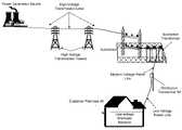
- FIG. 1is a diagram of an exemplary power distribution system with which the present invention may be employed
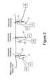
- FIG. 2is a diagram of a portion of an example power line communications system
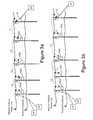
- FIGS. 3 a - bare schematic representations of a portion of example power line communications systems in accordance with example embodiments of the present invention.
- FIGS. 4 a - bare schematic representations of a portion of example power line communications systems in accordance with other example embodiments of the present invention.
- FIGS. 5 a - bare schematic representations of a portion of example power line communications systems in accordance with further example embodiments of the present invention.
- FIG. 6is a schematic representation of a portion of an example power line communications system in accordance with another example embodiment of the present invention.
- power distribution systemstypically include components for power generation, power transmission, and power delivery.
- a transmission substationtypically is used to increase the voltage from the power generation source to high voltage (HV) levels for long distance transmission on HV transmission lines to a substation.
- HVhigh voltage
- Typical voltages found on HV transmission linesrange from 69 kilovolts (kV) to in excess of 800 kV.
- power distribution systemsinclude MV power lines and LV power lines.
- MVtypically ranges from about 1000 V to about 100 kV and LV typically ranges from about 100 V to about 240 V.
- Transformersare used to convert between the respective voltage portions, e.g., between the HV section and the MV section and between the MV section and the LV section. Transformers have a primary side for connection to a first voltage (e.g., the MV section) and a secondary side for outputting another (usually lower) voltage (e.g., the LV section).
- Such transformersare often referred to as distribution transformers or step down transformers, because they “step down” the voltage to some lower voltage. Transformers, therefore, provide voltage conversion for the power distribution system.
- poweris carried from substation transformer to a distribution transformer over one or more MV power lines. Power is carried from the distribution transformer to the customer premises via one or more LV power lines.
- a distribution transformermay function to distribute one, two, three, or more phase voltages to the customer premises, depending upon the demands of the user. In the United States, for example, these local distribution transformers typically feed anywhere from one to ten homes, depending upon the concentration of the customer premises in a particular area. Distribution transformers may be pole-top transformers located on a utility pole, pad-mounted transformers located on the ground, or transformers located under ground level.
- the PLCS of the present inventionmay communicate signals to and from communication devices at the customer premises through the LV power line, wirelessly, or via other means.
- the PLCSmay communicate enhanced power distribution service (EPDS) data such as automated meter reading power usage data.
- EPDSenhanced power distribution service
- FIG. 2One example of portion of such a PLCS is shown in FIG. 2 and includes one or more bypass devices 100 .
- This example embodiment of the present inventionmay employ a bypass device (BD) 100 to communicate data signals past the distribution transformer (e.g., either around or through the transformer).
- the BD 100may act as the gateway between the LV power line subnet (i.e., the devices that are communicatively coupled to the LV power lines) and the MV power line and communicates signals to and from user devices at the customer premises (CP) via the low voltage subnet 61 .
- the BD 100provides communication services for the user, which may include security management, routing of Internet Protocol (IP) packets, filtering data, access control, service level monitoring, signal processing and modulation/demodulation of signals transmitted over the power lines.
- IPInternet Protocol
- This example portion of a PLCSalso includes a backhaul point 10 .
- the backhaul point 10is an interface and gateway between a portion of a PLCS (e.g., an MV run) and a traditional non-power line telecommunications network.
- One or more backhaul points (BP) 10are communicatively coupled to an aggregation point (AP) 20 that in many embodiments may be at (e.g., co-located with), or connected to, the point of presence (POP) to the Internet.
- the BP 10may be connected to the AP 20 using any available mechanism, including fiber optic conductors, T-carrier, Synchronous Optical Network (SONET), or wireless techniques well known to those skilled in the art.
- the BP 10may include a transceiver suited for communicating through the communication medium.
- the AP 20may include a conventional Internet Protocol (IP) data packet router and may be directly connected to an Internet backbone thereby providing access to the Internet. Alternatively, the AP 20 may be connected to a core router (not shown), which provides access to the Internet, or other communication network. Depending on the configuration of the PLCS, a plurality of APs 20 may be connected to a single core router which provides Internet access.
- the core router(or AP 20 as the case may be) may route voice traffic to and from a voice service provider and route Internet traffic to and from an Internet service provider and/or video provider. The routing of packets to the appropriate provider may be determined by any suitable means such as by including information in the data packets to determine whether a packet is voice.
- the packetmay be routed to the voice service provider and, if not, the packet may be routed to the Internet service provider.
- the packetmay include information (which may be a portion of the address) to determine whether a packet is Internet data. If the packet is Internet data, the packet may be routed to the Internet service provider and, if not, the packet may be routed to the voice service provider. Additionally, if the packet includes voice, video or other time sensitive data, it may be accorded a higher priority to thereby reduce the latency thereof.
- a distribution point(not shown) between the BP 10 and the AP 20 .
- the distribution pointwhich include a router, may be coupled to a plurality of BPs 10 and provides routing functions between its BPs 10 and its AP 20 .
- a plurality of BPs 10are connected to each distribution point and each distribution point (of which there are a plurality) is coupled to the AP 20 , which provides access to the Internet.
- the PLCSalso may include a power line server (PLS) that is a computer system with memory for storing a database of information about the PLCS and includes a network element manager (NEM) that monitors and controls the PLCS.
- PLSallows network operations personnel to provision users and network equipment, manage customer data, and monitor system status, performance and usage.
- the PLSmay reside at a remote network operations center (NOC), and/or at a PLCS Point of Presence (POP), to oversee a group of communication devices via the Internet.
- NOCremote network operations center
- POPPoint of Presence
- the PLSmay provide an Internet identity to the network devices by assigning the devices (e.g., user devices, BDs 100 , (e.g., the LV modems and MV modems of BDs), BPs 10 , and AP 20 ) IP addresses and storing the IP addresses and other device identifying information (e.g., the device's location, address, serial number, etc.) in its memory.
- the PLSmay approve or deny user devices authorization requests, command status reports, statistics and measurements from the BDs, and BPs, and provide application software upgrades to the communication devices (e.g., BDs, BPs, and other devices).
- the PLSby collecting electric power distribution information and interfacing with utilities' back-end computer systems may provide enhanced power distribution services such as automated meter reading, outage detection, restoration detection, load balancing, distribution automation, Volt/Volt-Amp Reactance (Volt/VAr) management, and other similar functions.
- the PLSalso may be connected to one or more APs and/or core routers directly or through the Internet and therefore can communicate with any of the BDs, user devices, and BPs through the respective AP and/or core router.
- the PLCSmay further include indoor low voltage repeaters and outdoor low voltage repeaters (not shown).
- Indoor low voltage repeatersmay be plugged into a wall socket inside the customer premises.
- Outdoor low voltage repeatersmay be coupled to the external low voltage power line conductors extending from the transformer and therefore, be located between the customer premises and the BD 100 . Both the indoor low voltage repeaters and outdoor low voltage repeaters repeat data on the low voltage power line to extend the communication range of the BD 100 and power line modem(s) at the customer premises.
- data floworiginates from a user device, which provides the data to a power line modem (PLM) 50 , which is well-known in the art.
- PLMpower line modem
- Various electrical circuits within the customer's premisesdistribute LV power and data signals within the customer premises.
- the customerdraws power on demand by plugging a device into a power outlet.
- the customermay plug the PLM into a power outlet to digitally connect user devices to communicate data signals carried by the LV wiring.
- the PLMthus serves as an interface for user devices to access the PLCS.
- the PLMcan have a variety of interfaces for customer data appliances.
- a PLMcan include a RJ-11 Plain Old Telephone Service (POTS) connector, an RS-232 connector, a USB connector, a Ethernet 10 Base-T connector, RJ-45 connector, and the like.
- POTSPlain Old Telephone Service
- RS-232 connectorRS-232 connector
- USB connectorRS-232 connector
- Ethernet 10 Base-T connectora Ethernet 10 Base-T connector
- RJ-45 connectorEthernet 10 Base-T connector
- the user device connected to the PLMmay be any device capable of supplying data for transmission (or for receiving such data) including, but not limited to a computer, a telephone, a telephone answering machine, a fax, a digital cable box (e.g., for processing digital audio and video, which may then be supplied to a conventional television and for transmitting requests for video programming), a video game, a stereo, a videophone, a television (which may be a digital television), a video recording device (which may be a digital video recorder), a home network device, a utility meter, or other device.
- the PLMtransmits the data received from the user device through the LV power lines to a BD 100 and provides data received from the LV power line to the user device.
- the PLMmay also be integrated with the user device, which may be a computer.
- the functions of the PLMmay be integrated into a smart utility meter such as a gas meter, electric meter, water meter, or other utility meter to thereby provide automated meter reading (AMR).
- AMRautomated meter reading
- the BD 100typically transmits the data to (and receives the data from) the backhaul point 10 , which, in turn, transmits the data to (and receives the data from) the AP 20 .
- the AP 20then transmits the data to (and receives the data from) the appropriate destination (perhaps via a core router), which may be a network destination (such as an Internet address) in which case the packets are transmitted to, and pass through, numerous routers (herein routers are meant to include both network routers and switches) in order to arrive at the desired destination.
- the PLCSmay have a maximum communications distance (MCD) (along the MV power line) over which a BP 10 and a BD 100 may communicate reliably. In addition, this distance may vary from location to location (e.g., from street to street), which makes planning the PLCS network difficult. If, after installation, a communication link between a BD 100 and its BP 10 is unreliable, one option is to install a second BP 10 closer to the BD 100 to service the BD 100 .
- installation of BPs 10can be costly due to costs of installation time, equipment, and the necessity of providing a backhaul link, which may require installing a fiber optic cable or wireless backhaul link.
- the communications link between a BD 100 and its BP 10may be reliable at times and unreliable at other times and/or may become unreliable sometime after installation of the network.
- one solutionis to install a new BP 10 closer to the BD 100 for communications, to service the BD 100 .
- this solutionis costly.
- Another solution to the problemis to install a dedicated repeater between the BP 10 and the BD 100 .
- thisrequires sending personnel to perform the installation of the repeater (i.e., a truck roll), which can be costly and can take days or weeks to complete during which time the subscriber of the PLCS service may be without reliable service or without any service.
- the present inventionmay reduce the need to install additional BPs, backhaul links, and dedicated repeater devices by extending the reach of existing BPs beyond the MCD through the use of existing network elements.
- This example embodiment of the present inventionmay employ a BD 100 that provides communications to one or more user devices (e.g., via the LV power lines, wirelessly, via a coaxial cable, via a fiber optic link, via a twisted pair, or other suitable manner) that also can be configured to repeat communications for other network elements over a power line conductor (MV conductor or neutral conductor).
- Each BD 100may be communicatively coupled to a BP 10 via an upstream link (which may also include other repeating network elements) and receive commands through the upstream link.
- the PLSmay transmit a command to the BD 100 to enable or disable repeating along with configuration information that allows the BD 100 to determine what data is to be repeated (e.g., the address information of the devices for which the BD 100 is to repeat communications).
- configuration informationthat allows the BD 100 to determine what data is to be repeated (e.g., the address information of the devices for which the BD 100 is to repeat communications).
- FIG. 3 aillustrates a first example embodiment of the present invention.
- each BD 100may receive data and transmit the data back on the MV power line for reception by the adjacent BD 100 .
- the BDs 100 of FIG. 3 amay be communicatively coupled to one or more user devices at the customer premises via a user communications link.
- the user communications link and CPare shown in FIG. 3 a and subsequent figures only for BD 100 d , which in this embodiment is a low voltage power line link.
- BDs 100 a - dmay be communicatively coupled to one or more user devices by a user communications link, which may be one or more of a fiber optic link, a wireless link, coaxial cable link, twisted pair link, LV power line link, or other suitable link.
- a user communications linkwhich may be one or more of a fiber optic link, a wireless link, coaxial cable link, twisted pair link, LV power line link, or other suitable link.
- backhaul point 10may transmit a first data packet in a first signal over the MV power line.
- the first signalmay traverse link L 1 and be received by BD 100 a .
- BD 100 amay transmit the packet to the user device (e.g., via the low voltage power line, wirelessly, via a coax cable, via a fiber optic, via twisted pair, or in another manner as the case may be).
- the data packetis addressed to the BD 100 a itself, BD 100 a may process the packet as a command or request from the PLS.
- BD 100 amay demodulate, re-address, and retransmit the data onto the MV power line in a second data packet embodied in a second signal.
- the data included in the second data packetmay include the same data payload received in the first data packet, but may have a different destination address (e.g., media access control (MAC) address) and source address inserted by BD 100 a .
- MACmedia access control
- BD 100 amay use a routing table (e.g., an Address Resolution Protocol (ARP) table) to determine (1) the addresses (e.g., MAC or IP addresses) of devices for which the BD 100 should repeat, (2) addresses for user devices it services (e.g., MAC or IP addresses), and (3) the addresses (e.g., MAC address) that should be included as the destination address for each (e.g., user packet or BD 100 packet).
- ARPAddress Resolution Protocol
- the BD 100 amay insert the MAC address of BD 100 b as the destination address and transmit the second data packet onto the MV power line, which may traverse links L 1 and L 2 .
- Both the backhaul point 10 and BD 100 bmay receive the second data packet transmitted from BD 100 a .
- backhaul point 10may ignore the second data packet because, for example, the destination address of the second packet may not correspond to the address of backhaul point 10 , but instead correspond to the address of the BD 100 b .
- those devicese.g., BDs 100 and BP 10
- those receive packets without appropriate addressingtypically will ignore or discard the data packet.
- the demodulation, address comparison, and ignoring or discarding of such data packetsmay not always be repeated throughout the discussion herein.
- BD 100 bmay receive, demodulate, process, re-address (if necessary), modulate, and re-transmit the data (hereinafter collectively referred to as “repeat the data”) on to the MV power line in a third data packet in a third signal that may traverse links L 3 and L 2 .
- BD 100 amay ignore the third data packet and BD 100 c may repeat the data in a fourth data packet in a fourth signal for reception by BD 100 d via link L 4 , which may further repeat the data in a fifth data packet in a fifth signal for reception by another BD 100 (not shown). Additionally, and as discussed above, BDs 100 b - d also may process the data as a command or transmit the data to a user device if the data packet is address appropriately.
- upstream datamay include data transmitted to a BD 100 or backhaul point 10 from another BD 100 further downstream.
- upstream datamay include data received by the BD 100 or backhaul point 10 from one or more user devices (not shown in FIG. 3 a ) (hereinafter “user data”), including, but not limited to, data transmitted wirelessly, via the low voltage power lines, via a coaxial cable, via a fiber optic cable, via a coaxial cable, via a twisted pair, via surface wave, and/or via any other means or medium of transmission.
- upstream datamay include control data, which may be data originating from a BD 100 or backhaul point 10 such as in response to a request or command from the PLS, transmission of an alert or notification, transmission of measurement data (e.g., low voltage measurement, medium voltage measurement, temperature, etc.) or other data.
- control datamay be data originating from a BD 100 or backhaul point 10 such as in response to a request or command from the PLS, transmission of an alert or notification, transmission of measurement data (e.g., low voltage measurement, medium voltage measurement, temperature, etc.) or other data.
- BD 100 dmay transmit or repeat upstream data in a first upstream data packet via link L 4 for reception by BD 100 c .
- BD 100 c , 100 b , and 100 amay repeat the upstream data via links L 3 , L 2 , and L 1 , respectively.
- backhaul point 10may repeat the data onto the backhaul link for eventual reception by AP 20 .
- BD 100 c , BD 100 b , and BD 100 aalso may originate and transmit upstream control data and user data, which may be repeated by any upstream BDs 100 disposed between the originating BD 100 and BP 10 .
- FIG. 3 billustrates a second embodiment of the present invention.
- some of the BDs 100may repeat the data that they receive, while others do not.
- backhaul point 10may receive data from AP 20 via the backhaul link and transmit that data in a first data packet in a first signal over the MV power line.
- the first signalmay traverse links L 1 and L 2 and be received by BDs 100 a and 100 b , which may receive, demodulate the data packet.
- BD 100 amay process the packet as a command or transmit the data to a subscriber if the packet is appropriately addressed to BD 100 a . If the data packet is not appropriately addressed to BD 100 a , BD 100 a may ignore the packet.
- BD 100 bmay process the packet as a command, ignore the data, or transmit the data to a subscriber if the packet is appropriately addressed to BD 100 b . Additionally, if the destination address of the packet matches a destination in the routing table, BD 100 b may re-address and retransmit (i.e., repeat) the data onto the MV power line in a second data packet embodied in a second signal. The second signal may traverse links L 3 and L 4 and be received by BDs 100 c and 100 d , which may receive and demodulate the data packet.
- BD 100 cmay process the packet as a command or transmit the data to a subscriber if the data packet is appropriately addressed to BD 100 c . If the data packet is not appropriately addressed to BD 100 c , BD 100 c may ignore the data. BD 100 d also may process the data as a command, transmit the data to a subscriber if the packet is appropriately addressed to BD 100 d , or ignore the data if not appropriately addressed.
- BD 100 dmay re-address and retransmit (i.e., repeat) the data onto the MV power line in a third data packet embodied in a third signal, for reception of other BDs 100 further downstream (not shown).
- those BDs 100 and the backhaul point 10 that receive packets that do not have the appropriate destination addressmay ignore by the data packets.
- BD 100 dmay transmit or repeat upstream in a first upstream data packet, which may be received by BDs 100 c and 100 b .
- BD 100 cmay ignore the data packet while BD 100 b may repeat the data for reception by backhaul point 10 .
- backhaul point 10may transmit the data onto the backhaul link for eventual reception by AP 20 .
- every other BD 100repeats data
- other systemsmay repeat the data at every third, fourth, fifth, sixth, seventh, eighth, ninth, tenth, or other incremental BD 100 .
- some portion(s) of the PLCS network connected to a BP 10may repeat the data at every other BD 10 and other portion(s) may repeat the data at the third, fourth, fifth, sixth, seventh, eighth, ninth, tenth and/or other incremental BD 100 .
- the distance between the repeating BDs 100 and the number of non-repeating BDs 100 between repeating BDs 100may not be consistent throughout the PLCS or over an MV run.
- the distance between the repeating BDs 100 and the number of non-repeating BDs 100 between repeating BDs 100may not be constant and may be dynamically changed such as, for example, by commands transmitted from the PLS over the power lines. For example, if network conditions permit, it may be desirable to reduce the number of repeats to a given network element (BD 100 ) so as to reduce the latency of data and/or increase the available bandwidth for data communicated with that network element.
- an increase in humiditymay reduce power line noise in some areas, thereby permitting a reduction in the number of repeats for a device during certain times of the year such as in the summer months.
- certain types of datamay follow a different data path than others. For example, it may be desirable to repeat EPDS data from a given network element more than voice data from that network element because the EPDS data is not time sensitive while significant latency of voice data may be undesirable.
- the BDs 100may have different routing table or rules for different types of data. Additionally, for data being repeated more, the power levels of the transmitter may be dynamically reduced (in comparison to data be repeated less) because the data may need to go a comparatively shorter distance.
- the power reductionmay allow the data to be communicated a shorter distance thereby by allowing more reuse of the MV power line as a communications channel.
- BP 10may be transmitting a first data packet in a first signal onto the MV power line while BD 100 c is simultaneously, or prior to the complete reception of the first data packet, transmitting another data packet in a second signal (i.e., the signals can be transmitted during overlapping time periods).
- the power levels of the transmittersare appropriately set or controlled (e.g., set sufficiently low so that the signal may travel only to the adjacent transformer), neither signal will interfere with the other because no BD 100 (in this example) is positioned to receive both signals.
- the MV power line channel(and neutral conductor) may be used to communicate multiple signals in the same frequency band simultaneously and/or in overlapping time periods.
- the same BD 100repeats data packets for both upstream and for downstream communications
- other embodimentsmay include some BDs 100 that repeat only downstream data and others that repeat only upstream data, (which may use different frequency bands).
- the upstream data and downstream datamay be communicated via different communications schemes. For example, downstream data may be communicated via the embodiment of FIG. 3 b , and the upstream data may be communicated via the embodiment shown in FIG. 3 a (e.g., every device repeats).
- FIG. 4 aillustrates a third embodiment of the present invention.
- BD 100 cmay repeat data for both an “upstream” BD 100 b (i.e., is located between BD 100 c and the BP 10 ) and a downstream BD 100 d (i.e., is not located between BD 100 c and the BP 10 ).
- backhaul point 10may receive data via the backhaul link and transmit that data in a first data packet in a first signal over the MV power line.
- the first signalmay traverse link L 1 , L 2 , and L 5 and be received by BDs 100 a , 100 b , and 100 c , which may receive, demodulate the data packet.
- BD 100 amay process the packet as a command or transmit the data to a subscriber if the packet is appropriately addressed to BD 100 a . If the data packet is not appropriately addressed to BD 100 a , BD 100 a may ignore the packet.
- BD 100 bmay process the packet but typically will ignore the packet because backhaul point 10 typically will not transmit (address) data packets for reception by BD 100 b.
- BD 100 cmay process the packet as a command or transmit the data to a subscriber if the packet is appropriately addressed to BD 100 b .
- BD 100 bmay re-address and retransmit (i.e., repeat) the data onto the MV power line in a second data packet embodied in a second signal.
- the second signalmay traverse links L 3 and L 4 and be received by BDs 100 b and 100 d , which may receive and demodulate the data packet.
- BDs 100 b and 100 dmay process the packet as a command or transmit the data to a subscriber if the data packet is appropriately addressed. If the data packet is not appropriately addressed, BDs 100 b and/or 100 d may ignore the packet. In addition, if the destination address of the data packet matches a destination address in its routing table, BD 100 d may re-address and retransmit (i.e., repeat) the data onto the MV power line in a third data packet embodied in a third signal, for reception of other BDs 100 further downstream (not shown).
- This example embodimentmay be useful in the event of localized noise in which BD 100 c has better reception capabilities from backhaul point 10 than does BD 100 b .
- communications received by BD 100 b from BD 100 cmay be received more reliably than those from backhaul point 10 .
- BD 100 cmay be located at a less noisy, or quiet spot, which thereby permitting reliable communications with backhaul point 10 whereas the noise at BD 100 b does not.
- BD 100 dmay transmit or repeat upstream data in a first upstream data packet, which may be received by BDs 100 c and 100 b .
- BD 100 bmay ignore the data packet while BD 100 c may repeat the data for upstream reception by backhaul point 10 .
- BD 100 bmay transmit upstream data in a first upstream data packet, which may be received by BDs 100 a , 100 c and 100 d .
- BD 100 d and BD 100 amay ignore the data packet while BD 100 c may repeat the data for upstream reception by backhaul point 10 .
- BD 100 bmay transmit the data directly to BP 10 via Link L 5 because, for example, localized noise typically does not hinder transmissions.
- any of the BDs 100 of FIG. 3 a or 3 b , or in other figure herein,may also alternately transmit directly to the BP 10 , but might receive data via repeating BD 100 .
- backhaul point 10may transmit the data onto the backhaul link for eventual reception by AP 20 .
- FIG. 4 billustrates a fourth example embodiment of the present invention.
- the data flow illustrated by FIG. 4 bis substantially similar to that of FIG. 4 a .
- BDs 100 a , 100 b , and 100 dare not physically coupled to the medium voltage power line.
- BDs 100 a , 100 b , and 100 dmay be communicatively coupled to the neutral conductor that extends down the utility pole from the distribution transformer and, preferably, above the horizontal neutral conductor that typically extends from pole to pole.
- An inductive couplercomprising a magnetically permeable toroid, with one or more windings, that clamps around the conductor may be used.
- a “link budget”is a phrase sometimes used to indicate the amount of power necessary to provide a reliable communications link and is often measured in dBs.
- Various objects along the communications channelmay use up a portion of the link budget such as, for example, the MV power line (e.g., which may dissipate 0.5-3 dB per one hundred feet), and the MV coupler of the receiving device.
- the distribution transformersattenuate the data signals, they may not completely block the data signals from traveling through the distribution transformer from the MV power line to the neutral conductor connected to the transformer enclosure. Consequently, if the power of the data signal is of sufficient magnitude upon reaching the distribution transformer, the signals may travel from the MV power line through the distribution transformer (e.g., coupling from the primary to the secondary of the transformer and/or coupling to the transformer enclosure and neutral conductor via parasitic capacitances) and down the low voltage and/or neutral conductors connected to the distribution transformer with sufficient remaining energy to be received by the BD 100 . In other words, in some instances, the distribution transformer simply may be considered another object that consumes the link budget.
- BDs 100 a , 100 b , and 100 dmay be communicatively coupled to the neutral conductor that extends down the utility pole and receive the data signals from the MV power line in such a manner. It will be noted that while BDs 100 a , 100 b , and 100 d may not physically couple “around” the distribution transformer, for purposes of this specification they are referred to as bypass devices because they facilitate the data passing the distribution transformer to the customer premises.
- the transformermay further attenuate the signal to the noise floor (i.e., using up the remaining link budget) in which case the BD 100 may not reliably receive the signals on the neutral or LV conductors. Consequently, the system of FIG. 4 b has been designed so that BDs 100 a , 100 b , and 100 d are all located at a transformer that is adjacent to a transformer co-located with a BD 100 c or BP 10 that is coupled to the MV power line via a MV coupler.
- the close proximity of the BD 100 d and BD 100 b to BD 100 c , and the close proximity of BD 100 a to backhaul point 10result in less attenuation of the data signals via their transmission over the MV power line (for both upstream and downstream communications). Because there is less attenuation of the data signals via the MV power line over these communication channels, there is a greater link budget (power or SNR) remaining than what might be available should the signals have traversed longer MV links. In this embodiment, the close proximity, and associated lower MV power line attenuation, allow for enough remaining link budget for the data signals to travel through the distribution transformers (for both upstream and downstream communications).
- any or all of the BDs 100may be coupled to one or both LV energized conductors instead of, or in addition to, the neutral conductor for communicating via the MV power line.
- such BDs 100might communicate in a first frequency band over the MV power line and a second frequency band over the LV power lines to the one or more user devices.
- itmay be desirable to transmit data signals at a first (e.g., higher) power level when transmitting via a MV coupler onto the MV power line and to transmit data signals at a second (lower) power level when transmitting via the LV power line or neutral conductor to the MV power line.
- every BD 100may be coupled to the LV conductor(s) or neutral conductor extending vertically down from the distribution transformer and the data paths may be substantially similar to or identical to the data paths shown in FIG. 3 a.
- FIG. 5 aillustrates another example embodiment of the present invention.
- the data flow illustrated by FIG. 5 ais substantially similar to that of FIG. 3 b .
- BDs 100 a and 100 care not coupled to the MV power line and, therefore, do not include medium voltage couplers.
- BDs 100 a and 100 dmay be communicatively coupled to the neutral conductor that extends down the utility pole from the distribution transformer and preferably above the horizontal neutral conductor that typically extends from pole to pole.
- either or both of BDs 100 a and 100 dmay be communicatively coupled to one or both LV energized conductors instead of, or in addition to, being coupled to the neutral conductor.
- FIG. 5 billustrates still another example embodiment of the present invention.
- the data flow illustrated by FIG. 5 bis similar to that of FIG. 3 b except that the data is communicated over the neutral conductor instead of the MV power line.
- the backhaul point 10 and the BDs 100may be communicatively coupled to the horizontal neutral conductor that typically extends from pole to pole.
- this systemmay alleviate the need to employ medium voltage couplers altogether and instead employ a neutral coupler (if necessary) at each network element.
- FIG. 6illustrates another example embodiment of the present invention.
- the data flow illustrated by FIG. 6is similar to that of FIG. 3 a except that the data is communicated over the neutral conductor instead of the MV power line.
- the backhaul point 10 and the BDs 100may be communicatively coupled to the horizontal neutral conductor that typically extends from pole to pole.
- this systemalso may alleviate the need to employ medium voltage couplers altogether and instead employ a neutral coupler (if necessary) at each network element.
- the neutral conductormay be connected to ground at the utility poles.
- the grounded neutral conductor at the utility polemay attenuate (or ground) the data signals. Consequently, in some instances, it may be desirable to install a data impedance 501 on the neutral conductor that extends from the horizontal neutral conductor to ground.
- the data impedancemay be a low pass filter formed of ferrite toroids that impedes (or reduces) the amount of the energy of the data signals that is conducted to ground thereby permitting more of the data signal energy to remain on the horizontal neutral conductor to be detected by the BDs 100 and backhaul point 10 .
- the BP 10 and BDs 100 of the disclosed embodimentsmay be remotely configurable via commands communicated over the PLCS (e.g., via the MV power line and/or neutral conductor) from the PLS. Consequently, the present invention may dynamically change between topologies of various embodiments. For example, in response to one or more commands from the PLS, the devices configured to communicate via the embodiment of FIG. 3 a may be remotely reconfigured to communicate via the embodiment of FIG. 3 b and vice versa. Similarly, the devices configured to communicate via the embodiment FIG. 5 b may be remotely reconfigured to communicate via the embodiment of FIG. 6 and vice versa.
- any of the embodiments disclosed hereinmay employ one, two, or three power line MV conductors and/or one or more neutral conductors.
- some of the BDs 100 communicating with a first BP 10may be coupled to a first MV conductor, others may be coupled to a second MV conductor, and others and/or the BP 10 may be coupled to a third MV conductor.
- datamay be transmitted from a BD 100 coupled to a first MV conductor, received and repeated by a BD 100 coupled to a second MV conductor, received and repeated by a BD 100 coupled to a third MV conductor, received and repeated by a BD 100 coupled to a neutral conductor, and subsequently received by a BD 100 or BP 10 coupled to the first MV conductor.
- each set of BDs 100 coupled to each MV conductor or neutralmay employ a different embodiment.
- BDs 100 coupled to a first MV conductormay employ the embodiment and data flow depicted in FIG. 3 b
- BDs 100 coupled to a second MV conductor(which may or may not run parallel to the first conductor) may employ the embodiment and data flow depicted in FIG. 4 b
- BDs 100 coupled to a neutral conductormay employ the embodiment and data flow depicted in FIG. 6 .
- any suitable type of data signalmay communicated via each embodiment or over each link.
- any suitable signal modulation used in communicationsCode Division Multiple Access (CDMA), Time Division Multiple Access (TDMA), Frequency Division Multiplex (FDM), Orthogonal Frequency Division Multiplex (OFDM), and the like
- IEEE 802.11(a, b, or g) signal setand/or IEEE 802.16 (e.g., WIMAX which may be OFDM) signal set
- OFDMincluding WIMAX
- WIMAXmay be used for any or all of communications via the LV power lines, MV power lines, and/or neutral conductor.
- Use of a WIMAX signal, HomePlug or other signal described hereinmay require frequency shifting the signal to the desired frequency band.
- a modulation scheme producing a wideband signalsuch as CDMA or OFDM that is relatively flat in the spectral domain may be used to reduce radiated interference to other systems while still delivering high data communication rates.
- each link in the embodimentsmay be orthogonal to any or all of the other links.
- Link L 1may use a first frequency band
- Link L 2may use a second frequency band
- Link L 3may use a third frequency band, wherein all of the frequency bands may different so as not to interfere with each other.
- Link L 4also might use the first frequency band because, as discussed above, the devices using the first frequency may be sufficiently far apart so that the signals attenuate between those sections thereby allowing for reuse of the frequency band and simultaneous communications in that frequency at different sections of the MV power line or neutral conductor.
- orthogonal linksreferring to FIG.
- Link L 1may use an OFDM signal
- Link L 2may use a surface wave signal
- Link L 3may use a UWB signal so that all of the signals do not interfere with each other.
- any or all of the linksmay include multiple signals.
- any of the linksmay include a first signal type, such as a conventional frequency band conductive signal (e.g., an OFDM signal), and also may include one or more other signal types orthogonal to the first signal type, such as UWB and/or surface wave signals.
- an alternate embodiment of a PLCS systemmay use ultra wideband signals or surface wave signals (Goubau waves) to provide communications.
- BDs 100 or a BP 10 coupled to the MV conductorit may be desirable to couple the device to the connecting conductor that connects the MV power line conductor to the distribution transformer via, for example, an inductive coupler.
- energy from the transmissionmay couple to other conductors or may traverse a return path that includes other conductors.
- signals transmitted on a first power line conductormay cross couple to other power line conductors and/or the neutral conductor.
- signals transmitted on a first power line conductormay travel a return path that includes another power line conductor and/or the neutral conductor.
- the transmitting devicemay include two couplers to transmit substantially equal, but opposite in polarity, signals onto the two MV overhead conductors.
- the receiving devicemay include one or two couplers.
- the LV transmissionsmay be transmitted differentially onto two energized conductors and may be a UWB signal, an OFDM signal, a WIMAX signal, or other signal.
- the backhaul linkmay be any suitable medium including a digital subscriber line (DSL), a coaxial cable (e.g., DOCSIS), and/or a WIMAX or other wireless link.
Landscapes
- Engineering & Computer Science (AREA)
- Computer Networks & Wireless Communication (AREA)
- Signal Processing (AREA)
- Power Engineering (AREA)
- Cable Transmission Systems, Equalization Of Radio And Reduction Of Echo (AREA)
Abstract
Description
Claims (31)
Priority Applications (1)
| Application Number | Priority Date | Filing Date | Title |
|---|---|---|---|
| US11/831,184US7450001B2 (en) | 2005-04-04 | 2007-07-31 | Power line communications system and method |
Applications Claiming Priority (2)
| Application Number | Priority Date | Filing Date | Title |
|---|---|---|---|
| US11/097,132US7265664B2 (en) | 2005-04-04 | 2005-04-04 | Power line communications system and method |
| US11/831,184US7450001B2 (en) | 2005-04-04 | 2007-07-31 | Power line communications system and method |
Related Parent Applications (1)
| Application Number | Title | Priority Date | Filing Date |
|---|---|---|---|
| US11/097,132ContinuationUS7265664B2 (en) | 2005-04-04 | 2005-04-04 | Power line communications system and method |
Publications (2)
| Publication Number | Publication Date |
|---|---|
| US20070268124A1 US20070268124A1 (en) | 2007-11-22 |
| US7450001B2true US7450001B2 (en) | 2008-11-11 |
Family
ID=37069696
Family Applications (2)
| Application Number | Title | Priority Date | Filing Date |
|---|---|---|---|
| US11/097,132Expired - Fee RelatedUS7265664B2 (en) | 2005-04-04 | 2005-04-04 | Power line communications system and method |
| US11/831,184Expired - Fee RelatedUS7450001B2 (en) | 2005-04-04 | 2007-07-31 | Power line communications system and method |
Family Applications Before (1)
| Application Number | Title | Priority Date | Filing Date |
|---|---|---|---|
| US11/097,132Expired - Fee RelatedUS7265664B2 (en) | 2005-04-04 | 2005-04-04 | Power line communications system and method |
Country Status (1)
| Country | Link |
|---|---|
| US (2) | US7265664B2 (en) |
Cited By (163)
| Publication number | Priority date | Publication date | Assignee | Title |
|---|---|---|---|---|
| US8198998B1 (en)* | 2008-01-23 | 2012-06-12 | Adaptive Networks, Inc. | Identification of power line locations by power line signatures |
| US8428511B1 (en)* | 2007-08-10 | 2013-04-23 | Nextel Communications Inc. | System and method for a high available and survivable communication system |
| US8897697B1 (en) | 2013-11-06 | 2014-11-25 | At&T Intellectual Property I, Lp | Millimeter-wave surface-wave communications |
| US9113347B2 (en) | 2012-12-05 | 2015-08-18 | At&T Intellectual Property I, Lp | Backhaul link for distributed antenna system |
| US9209902B2 (en) | 2013-12-10 | 2015-12-08 | At&T Intellectual Property I, L.P. | Quasi-optical coupler |
| US9312919B1 (en) | 2014-10-21 | 2016-04-12 | At&T Intellectual Property I, Lp | Transmission device with impairment compensation and methods for use therewith |
| US9461706B1 (en) | 2015-07-31 | 2016-10-04 | At&T Intellectual Property I, Lp | Method and apparatus for exchanging communication signals |
| US9490869B1 (en) | 2015-05-14 | 2016-11-08 | At&T Intellectual Property I, L.P. | Transmission medium having multiple cores and methods for use therewith |
| US9503189B2 (en) | 2014-10-10 | 2016-11-22 | At&T Intellectual Property I, L.P. | Method and apparatus for arranging communication sessions in a communication system |
| US9509415B1 (en) | 2015-06-25 | 2016-11-29 | At&T Intellectual Property I, L.P. | Methods and apparatus for inducing a fundamental wave mode on a transmission medium |
| US9520945B2 (en) | 2014-10-21 | 2016-12-13 | At&T Intellectual Property I, L.P. | Apparatus for providing communication services and methods thereof |
| US9525524B2 (en) | 2013-05-31 | 2016-12-20 | At&T Intellectual Property I, L.P. | Remote distributed antenna system |
| US9525210B2 (en) | 2014-10-21 | 2016-12-20 | At&T Intellectual Property I, L.P. | Guided-wave transmission device with non-fundamental mode propagation and methods for use therewith |
| US9531427B2 (en) | 2014-11-20 | 2016-12-27 | At&T Intellectual Property I, L.P. | Transmission device with mode division multiplexing and methods for use therewith |
| US9564947B2 (en) | 2014-10-21 | 2017-02-07 | At&T Intellectual Property I, L.P. | Guided-wave transmission device with diversity and methods for use therewith |
| US9577306B2 (en) | 2014-10-21 | 2017-02-21 | At&T Intellectual Property I, L.P. | Guided-wave transmission device and methods for use therewith |
| US9608692B2 (en) | 2015-06-11 | 2017-03-28 | At&T Intellectual Property I, L.P. | Repeater and methods for use therewith |
| US9608740B2 (en) | 2015-07-15 | 2017-03-28 | At&T Intellectual Property I, L.P. | Method and apparatus for launching a wave mode that mitigates interference |
| US9615269B2 (en) | 2014-10-02 | 2017-04-04 | At&T Intellectual Property I, L.P. | Method and apparatus that provides fault tolerance in a communication network |
| US9628116B2 (en) | 2015-07-14 | 2017-04-18 | At&T Intellectual Property I, L.P. | Apparatus and methods for transmitting wireless signals |
| US9628854B2 (en) | 2014-09-29 | 2017-04-18 | At&T Intellectual Property I, L.P. | Method and apparatus for distributing content in a communication network |
| US9640850B2 (en) | 2015-06-25 | 2017-05-02 | At&T Intellectual Property I, L.P. | Methods and apparatus for inducing a non-fundamental wave mode on a transmission medium |
| US9654173B2 (en) | 2014-11-20 | 2017-05-16 | At&T Intellectual Property I, L.P. | Apparatus for powering a communication device and methods thereof |
| US9653770B2 (en) | 2014-10-21 | 2017-05-16 | At&T Intellectual Property I, L.P. | Guided wave coupler, coupling module and methods for use therewith |
| US9667317B2 (en) | 2015-06-15 | 2017-05-30 | At&T Intellectual Property I, L.P. | Method and apparatus for providing security using network traffic adjustments |
| US9680670B2 (en) | 2014-11-20 | 2017-06-13 | At&T Intellectual Property I, L.P. | Transmission device with channel equalization and control and methods for use therewith |
| US9685992B2 (en) | 2014-10-03 | 2017-06-20 | At&T Intellectual Property I, L.P. | Circuit panel network and methods thereof |
| US9692101B2 (en) | 2014-08-26 | 2017-06-27 | At&T Intellectual Property I, L.P. | Guided wave couplers for coupling electromagnetic waves between a waveguide surface and a surface of a wire |
| US9705571B2 (en) | 2015-09-16 | 2017-07-11 | At&T Intellectual Property I, L.P. | Method and apparatus for use with a radio distributed antenna system |
| US9705561B2 (en) | 2015-04-24 | 2017-07-11 | At&T Intellectual Property I, L.P. | Directional coupling device and methods for use therewith |
| US9722318B2 (en) | 2015-07-14 | 2017-08-01 | At&T Intellectual Property I, L.P. | Method and apparatus for coupling an antenna to a device |
| US9729197B2 (en) | 2015-10-01 | 2017-08-08 | At&T Intellectual Property I, L.P. | Method and apparatus for communicating network management traffic over a network |
| US9735833B2 (en) | 2015-07-31 | 2017-08-15 | At&T Intellectual Property I, L.P. | Method and apparatus for communications management in a neighborhood network |
| US9742462B2 (en) | 2014-12-04 | 2017-08-22 | At&T Intellectual Property I, L.P. | Transmission medium and communication interfaces and methods for use therewith |
| US9748626B2 (en) | 2015-05-14 | 2017-08-29 | At&T Intellectual Property I, L.P. | Plurality of cables having different cross-sectional shapes which are bundled together to form a transmission medium |
| US9749053B2 (en) | 2015-07-23 | 2017-08-29 | At&T Intellectual Property I, L.P. | Node device, repeater and methods for use therewith |
| US9749013B2 (en) | 2015-03-17 | 2017-08-29 | At&T Intellectual Property I, L.P. | Method and apparatus for reducing attenuation of electromagnetic waves guided by a transmission medium |
| US9755697B2 (en) | 2014-09-15 | 2017-09-05 | At&T Intellectual Property I, L.P. | Method and apparatus for sensing a condition in a transmission medium of electromagnetic waves |
| US9762289B2 (en) | 2014-10-14 | 2017-09-12 | At&T Intellectual Property I, L.P. | Method and apparatus for transmitting or receiving signals in a transportation system |
| US9769020B2 (en) | 2014-10-21 | 2017-09-19 | At&T Intellectual Property I, L.P. | Method and apparatus for responding to events affecting communications in a communication network |
| US9769128B2 (en) | 2015-09-28 | 2017-09-19 | At&T Intellectual Property I, L.P. | Method and apparatus for encryption of communications over a network |
| US9780834B2 (en) | 2014-10-21 | 2017-10-03 | At&T Intellectual Property I, L.P. | Method and apparatus for transmitting electromagnetic waves |
| US9793951B2 (en) | 2015-07-15 | 2017-10-17 | At&T Intellectual Property I, L.P. | Method and apparatus for launching a wave mode that mitigates interference |
| US9793954B2 (en) | 2015-04-28 | 2017-10-17 | At&T Intellectual Property I, L.P. | Magnetic coupling device and methods for use therewith |
| US9793955B2 (en) | 2015-04-24 | 2017-10-17 | At&T Intellectual Property I, Lp | Passive electrical coupling device and methods for use therewith |
| US9800327B2 (en) | 2014-11-20 | 2017-10-24 | At&T Intellectual Property I, L.P. | Apparatus for controlling operations of a communication device and methods thereof |
| US9820146B2 (en) | 2015-06-12 | 2017-11-14 | At&T Intellectual Property I, L.P. | Method and apparatus for authentication and identity management of communicating devices |
| US9838896B1 (en) | 2016-12-09 | 2017-12-05 | At&T Intellectual Property I, L.P. | Method and apparatus for assessing network coverage |
| US9836957B2 (en) | 2015-07-14 | 2017-12-05 | At&T Intellectual Property I, L.P. | Method and apparatus for communicating with premises equipment |
| US9847566B2 (en) | 2015-07-14 | 2017-12-19 | At&T Intellectual Property I, L.P. | Method and apparatus for adjusting a field of a signal to mitigate interference |
| US9847850B2 (en) | 2014-10-14 | 2017-12-19 | At&T Intellectual Property I, L.P. | Method and apparatus for adjusting a mode of communication in a communication network |
| US9853342B2 (en) | 2015-07-14 | 2017-12-26 | At&T Intellectual Property I, L.P. | Dielectric transmission medium connector and methods for use therewith |
| US9860075B1 (en) | 2016-08-26 | 2018-01-02 | At&T Intellectual Property I, L.P. | Method and communication node for broadband distribution |
| US9865911B2 (en) | 2015-06-25 | 2018-01-09 | At&T Intellectual Property I, L.P. | Waveguide system for slot radiating first electromagnetic waves that are combined into a non-fundamental wave mode second electromagnetic wave on a transmission medium |
| US9866309B2 (en) | 2015-06-03 | 2018-01-09 | At&T Intellectual Property I, Lp | Host node device and methods for use therewith |
| US9871282B2 (en) | 2015-05-14 | 2018-01-16 | At&T Intellectual Property I, L.P. | At least one transmission medium having a dielectric surface that is covered at least in part by a second dielectric |
| US9871283B2 (en) | 2015-07-23 | 2018-01-16 | At&T Intellectual Property I, Lp | Transmission medium having a dielectric core comprised of plural members connected by a ball and socket configuration |
| US9876264B2 (en) | 2015-10-02 | 2018-01-23 | At&T Intellectual Property I, Lp | Communication system, guided wave switch and methods for use therewith |
| US9876571B2 (en) | 2015-02-20 | 2018-01-23 | At&T Intellectual Property I, Lp | Guided-wave transmission device with non-fundamental mode propagation and methods for use therewith |
| US9876605B1 (en) | 2016-10-21 | 2018-01-23 | At&T Intellectual Property I, L.P. | Launcher and coupling system to support desired guided wave mode |
| US9882277B2 (en) | 2015-10-02 | 2018-01-30 | At&T Intellectual Property I, Lp | Communication device and antenna assembly with actuated gimbal mount |
| US9882257B2 (en) | 2015-07-14 | 2018-01-30 | At&T Intellectual Property I, L.P. | Method and apparatus for launching a wave mode that mitigates interference |
| US9893795B1 (en) | 2016-12-07 | 2018-02-13 | At&T Intellectual Property I, Lp | Method and repeater for broadband distribution |
| US9906269B2 (en) | 2014-09-17 | 2018-02-27 | At&T Intellectual Property I, L.P. | Monitoring and mitigating conditions in a communication network |
| US9904535B2 (en) | 2015-09-14 | 2018-02-27 | At&T Intellectual Property I, L.P. | Method and apparatus for distributing software |
| US9913139B2 (en) | 2015-06-09 | 2018-03-06 | At&T Intellectual Property I, L.P. | Signal fingerprinting for authentication of communicating devices |
| US9912382B2 (en) | 2015-06-03 | 2018-03-06 | At&T Intellectual Property I, Lp | Network termination and methods for use therewith |
| US9912027B2 (en) | 2015-07-23 | 2018-03-06 | At&T Intellectual Property I, L.P. | Method and apparatus for exchanging communication signals |
| US9911020B1 (en) | 2016-12-08 | 2018-03-06 | At&T Intellectual Property I, L.P. | Method and apparatus for tracking via a radio frequency identification device |
| US9912419B1 (en) | 2016-08-24 | 2018-03-06 | At&T Intellectual Property I, L.P. | Method and apparatus for managing a fault in a distributed antenna system |
| US9917341B2 (en) | 2015-05-27 | 2018-03-13 | At&T Intellectual Property I, L.P. | Apparatus and method for launching electromagnetic waves and for modifying radial dimensions of the propagating electromagnetic waves |
| US9927517B1 (en) | 2016-12-06 | 2018-03-27 | At&T Intellectual Property I, L.P. | Apparatus and methods for sensing rainfall |
| US9948354B2 (en) | 2015-04-28 | 2018-04-17 | At&T Intellectual Property I, L.P. | Magnetic coupling device with reflective plate and methods for use therewith |
| US9948333B2 (en) | 2015-07-23 | 2018-04-17 | At&T Intellectual Property I, L.P. | Method and apparatus for wireless communications to mitigate interference |
| US9954287B2 (en) | 2014-11-20 | 2018-04-24 | At&T Intellectual Property I, L.P. | Apparatus for converting wireless signals and electromagnetic waves and methods thereof |
| US9967173B2 (en) | 2015-07-31 | 2018-05-08 | At&T Intellectual Property I, L.P. | Method and apparatus for authentication and identity management of communicating devices |
| US9973940B1 (en) | 2017-02-27 | 2018-05-15 | At&T Intellectual Property I, L.P. | Apparatus and methods for dynamic impedance matching of a guided wave launcher |
| US9991580B2 (en) | 2016-10-21 | 2018-06-05 | At&T Intellectual Property I, L.P. | Launcher and coupling system for guided wave mode cancellation |
| US9998870B1 (en) | 2016-12-08 | 2018-06-12 | At&T Intellectual Property I, L.P. | Method and apparatus for proximity sensing |
| US9997819B2 (en) | 2015-06-09 | 2018-06-12 | At&T Intellectual Property I, L.P. | Transmission medium and method for facilitating propagation of electromagnetic waves via a core |
| US9999038B2 (en) | 2013-05-31 | 2018-06-12 | At&T Intellectual Property I, L.P. | Remote distributed antenna system |
| US10009067B2 (en) | 2014-12-04 | 2018-06-26 | At&T Intellectual Property I, L.P. | Method and apparatus for configuring a communication interface |
| US10009065B2 (en) | 2012-12-05 | 2018-06-26 | At&T Intellectual Property I, L.P. | Backhaul link for distributed antenna system |
| US10009063B2 (en) | 2015-09-16 | 2018-06-26 | At&T Intellectual Property I, L.P. | Method and apparatus for use with a radio distributed antenna system having an out-of-band reference signal |
| US10009901B2 (en) | 2015-09-16 | 2018-06-26 | At&T Intellectual Property I, L.P. | Method, apparatus, and computer-readable storage medium for managing utilization of wireless resources between base stations |
| US10020587B2 (en) | 2015-07-31 | 2018-07-10 | At&T Intellectual Property I, L.P. | Radial antenna and methods for use therewith |
| US10020844B2 (en) | 2016-12-06 | 2018-07-10 | T&T Intellectual Property I, L.P. | Method and apparatus for broadcast communication via guided waves |
| US10027397B2 (en) | 2016-12-07 | 2018-07-17 | At&T Intellectual Property I, L.P. | Distributed antenna system and methods for use therewith |
| US10033108B2 (en) | 2015-07-14 | 2018-07-24 | At&T Intellectual Property I, L.P. | Apparatus and methods for generating an electromagnetic wave having a wave mode that mitigates interference |
| US10033107B2 (en) | 2015-07-14 | 2018-07-24 | At&T Intellectual Property I, L.P. | Method and apparatus for coupling an antenna to a device |
| US10044409B2 (en) | 2015-07-14 | 2018-08-07 | At&T Intellectual Property I, L.P. | Transmission medium and methods for use therewith |
| US10051629B2 (en) | 2015-09-16 | 2018-08-14 | At&T Intellectual Property I, L.P. | Method and apparatus for use with a radio distributed antenna system having an in-band reference signal |
| US10051483B2 (en) | 2015-10-16 | 2018-08-14 | At&T Intellectual Property I, L.P. | Method and apparatus for directing wireless signals |
| US10069535B2 (en) | 2016-12-08 | 2018-09-04 | At&T Intellectual Property I, L.P. | Apparatus and methods for launching electromagnetic waves having a certain electric field structure |
| US10074890B2 (en) | 2015-10-02 | 2018-09-11 | At&T Intellectual Property I, L.P. | Communication device and antenna with integrated light assembly |
| US10079661B2 (en) | 2015-09-16 | 2018-09-18 | At&T Intellectual Property I, L.P. | Method and apparatus for use with a radio distributed antenna system having a clock reference |
| US10090594B2 (en) | 2016-11-23 | 2018-10-02 | At&T Intellectual Property I, L.P. | Antenna system having structural configurations for assembly |
| US10090606B2 (en) | 2015-07-15 | 2018-10-02 | At&T Intellectual Property I, L.P. | Antenna system with dielectric array and methods for use therewith |
| US10103801B2 (en) | 2015-06-03 | 2018-10-16 | At&T Intellectual Property I, L.P. | Host node device and methods for use therewith |
| US10103422B2 (en) | 2016-12-08 | 2018-10-16 | At&T Intellectual Property I, L.P. | Method and apparatus for mounting network devices |
| US10136434B2 (en) | 2015-09-16 | 2018-11-20 | At&T Intellectual Property I, L.P. | Method and apparatus for use with a radio distributed antenna system having an ultra-wideband control channel |
| US10135146B2 (en) | 2016-10-18 | 2018-11-20 | At&T Intellectual Property I, L.P. | Apparatus and methods for launching guided waves via circuits |
| US10135147B2 (en) | 2016-10-18 | 2018-11-20 | At&T Intellectual Property I, L.P. | Apparatus and methods for launching guided waves via an antenna |
| US10135145B2 (en) | 2016-12-06 | 2018-11-20 | At&T Intellectual Property I, L.P. | Apparatus and methods for generating an electromagnetic wave along a transmission medium |
| US10139820B2 (en) | 2016-12-07 | 2018-11-27 | At&T Intellectual Property I, L.P. | Method and apparatus for deploying equipment of a communication system |
| US10142086B2 (en) | 2015-06-11 | 2018-11-27 | At&T Intellectual Property I, L.P. | Repeater and methods for use therewith |
| US10148016B2 (en) | 2015-07-14 | 2018-12-04 | At&T Intellectual Property I, L.P. | Apparatus and methods for communicating utilizing an antenna array |
| US10144036B2 (en) | 2015-01-30 | 2018-12-04 | At&T Intellectual Property I, L.P. | Method and apparatus for mitigating interference affecting a propagation of electromagnetic waves guided by a transmission medium |
| US10154493B2 (en) | 2015-06-03 | 2018-12-11 | At&T Intellectual Property I, L.P. | Network termination and methods for use therewith |
| US10170840B2 (en) | 2015-07-14 | 2019-01-01 | At&T Intellectual Property I, L.P. | Apparatus and methods for sending or receiving electromagnetic signals |
| US10168695B2 (en) | 2016-12-07 | 2019-01-01 | At&T Intellectual Property I, L.P. | Method and apparatus for controlling an unmanned aircraft |
| US10178445B2 (en) | 2016-11-23 | 2019-01-08 | At&T Intellectual Property I, L.P. | Methods, devices, and systems for load balancing between a plurality of waveguides |
| US10205655B2 (en) | 2015-07-14 | 2019-02-12 | At&T Intellectual Property I, L.P. | Apparatus and methods for communicating utilizing an antenna array and multiple communication paths |
| US10225025B2 (en) | 2016-11-03 | 2019-03-05 | At&T Intellectual Property I, L.P. | Method and apparatus for detecting a fault in a communication system |
| US10224634B2 (en) | 2016-11-03 | 2019-03-05 | At&T Intellectual Property I, L.P. | Methods and apparatus for adjusting an operational characteristic of an antenna |
| US10243270B2 (en) | 2016-12-07 | 2019-03-26 | At&T Intellectual Property I, L.P. | Beam adaptive multi-feed dielectric antenna system and methods for use therewith |
| US10243784B2 (en) | 2014-11-20 | 2019-03-26 | At&T Intellectual Property I, L.P. | System for generating topology information and methods thereof |
| US10264586B2 (en) | 2016-12-09 | 2019-04-16 | At&T Mobility Ii Llc | Cloud-based packet controller and methods for use therewith |
| US10291334B2 (en) | 2016-11-03 | 2019-05-14 | At&T Intellectual Property I, L.P. | System for detecting a fault in a communication system |
| US10291311B2 (en) | 2016-09-09 | 2019-05-14 | At&T Intellectual Property I, L.P. | Method and apparatus for mitigating a fault in a distributed antenna system |
| US10298293B2 (en) | 2017-03-13 | 2019-05-21 | At&T Intellectual Property I, L.P. | Apparatus of communication utilizing wireless network devices |
| US10305190B2 (en) | 2016-12-01 | 2019-05-28 | At&T Intellectual Property I, L.P. | Reflecting dielectric antenna system and methods for use therewith |
| US10312567B2 (en) | 2016-10-26 | 2019-06-04 | At&T Intellectual Property I, L.P. | Launcher with planar strip antenna and methods for use therewith |
| US10320586B2 (en) | 2015-07-14 | 2019-06-11 | At&T Intellectual Property I, L.P. | Apparatus and methods for generating non-interfering electromagnetic waves on an insulated transmission medium |
| US10326689B2 (en) | 2016-12-08 | 2019-06-18 | At&T Intellectual Property I, L.P. | Method and system for providing alternative communication paths |
| US10326494B2 (en) | 2016-12-06 | 2019-06-18 | At&T Intellectual Property I, L.P. | Apparatus for measurement de-embedding and methods for use therewith |
| US10340983B2 (en) | 2016-12-09 | 2019-07-02 | At&T Intellectual Property I, L.P. | Method and apparatus for surveying remote sites via guided wave communications |
| US10340573B2 (en) | 2016-10-26 | 2019-07-02 | At&T Intellectual Property I, L.P. | Launcher with cylindrical coupling device and methods for use therewith |
| US10341142B2 (en) | 2015-07-14 | 2019-07-02 | At&T Intellectual Property I, L.P. | Apparatus and methods for generating non-interfering electromagnetic waves on an uninsulated conductor |
| US10340603B2 (en) | 2016-11-23 | 2019-07-02 | At&T Intellectual Property I, L.P. | Antenna system having shielded structural configurations for assembly |
| US10340600B2 (en) | 2016-10-18 | 2019-07-02 | At&T Intellectual Property I, L.P. | Apparatus and methods for launching guided waves via plural waveguide systems |
| US10340601B2 (en) | 2016-11-23 | 2019-07-02 | At&T Intellectual Property I, L.P. | Multi-antenna system and methods for use therewith |
| US10348391B2 (en) | 2015-06-03 | 2019-07-09 | At&T Intellectual Property I, L.P. | Client node device with frequency conversion and methods for use therewith |
| US10355367B2 (en) | 2015-10-16 | 2019-07-16 | At&T Intellectual Property I, L.P. | Antenna structure for exchanging wireless signals |
| US10361489B2 (en) | 2016-12-01 | 2019-07-23 | At&T Intellectual Property I, L.P. | Dielectric dish antenna system and methods for use therewith |
| US10359749B2 (en) | 2016-12-07 | 2019-07-23 | At&T Intellectual Property I, L.P. | Method and apparatus for utilities management via guided wave communication |
| US10374316B2 (en) | 2016-10-21 | 2019-08-06 | At&T Intellectual Property I, L.P. | System and dielectric antenna with non-uniform dielectric |
| US10382976B2 (en) | 2016-12-06 | 2019-08-13 | At&T Intellectual Property I, L.P. | Method and apparatus for managing wireless communications based on communication paths and network device positions |
| US10389029B2 (en) | 2016-12-07 | 2019-08-20 | At&T Intellectual Property I, L.P. | Multi-feed dielectric antenna system with core selection and methods for use therewith |
| US10389037B2 (en) | 2016-12-08 | 2019-08-20 | At&T Intellectual Property I, L.P. | Apparatus and methods for selecting sections of an antenna array and use therewith |
| US10396887B2 (en) | 2015-06-03 | 2019-08-27 | At&T Intellectual Property I, L.P. | Client node device and methods for use therewith |
| US10411356B2 (en) | 2016-12-08 | 2019-09-10 | At&T Intellectual Property I, L.P. | Apparatus and methods for selectively targeting communication devices with an antenna array |
| US10439675B2 (en) | 2016-12-06 | 2019-10-08 | At&T Intellectual Property I, L.P. | Method and apparatus for repeating guided wave communication signals |
| US10446936B2 (en) | 2016-12-07 | 2019-10-15 | At&T Intellectual Property I, L.P. | Multi-feed dielectric antenna system and methods for use therewith |
| US10498044B2 (en) | 2016-11-03 | 2019-12-03 | At&T Intellectual Property I, L.P. | Apparatus for configuring a surface of an antenna |
| US10530505B2 (en) | 2016-12-08 | 2020-01-07 | At&T Intellectual Property I, L.P. | Apparatus and methods for launching electromagnetic waves along a transmission medium |
| US10535928B2 (en) | 2016-11-23 | 2020-01-14 | At&T Intellectual Property I, L.P. | Antenna system and methods for use therewith |
| US10547348B2 (en) | 2016-12-07 | 2020-01-28 | At&T Intellectual Property I, L.P. | Method and apparatus for switching transmission mediums in a communication system |
| US10601494B2 (en) | 2016-12-08 | 2020-03-24 | At&T Intellectual Property I, L.P. | Dual-band communication device and method for use therewith |
| US10637149B2 (en) | 2016-12-06 | 2020-04-28 | At&T Intellectual Property I, L.P. | Injection molded dielectric antenna and methods for use therewith |
| US10650940B2 (en) | 2015-05-15 | 2020-05-12 | At&T Intellectual Property I, L.P. | Transmission medium having a conductive material and methods for use therewith |
| US10665942B2 (en) | 2015-10-16 | 2020-05-26 | At&T Intellectual Property I, L.P. | Method and apparatus for adjusting wireless communications |
| US10679767B2 (en) | 2015-05-15 | 2020-06-09 | At&T Intellectual Property I, L.P. | Transmission medium having a conductive material and methods for use therewith |
| US10694379B2 (en) | 2016-12-06 | 2020-06-23 | At&T Intellectual Property I, L.P. | Waveguide system with device-based authentication and methods for use therewith |
| US10727599B2 (en) | 2016-12-06 | 2020-07-28 | At&T Intellectual Property I, L.P. | Launcher with slot antenna and methods for use therewith |
| US10755542B2 (en) | 2016-12-06 | 2020-08-25 | At&T Intellectual Property I, L.P. | Method and apparatus for surveillance via guided wave communication |
| US10777873B2 (en) | 2016-12-08 | 2020-09-15 | At&T Intellectual Property I, L.P. | Method and apparatus for mounting network devices |
| US10784670B2 (en) | 2015-07-23 | 2020-09-22 | At&T Intellectual Property I, L.P. | Antenna support for aligning an antenna |
| US10811767B2 (en) | 2016-10-21 | 2020-10-20 | At&T Intellectual Property I, L.P. | System and dielectric antenna with convex dielectric radome |
| US10819035B2 (en) | 2016-12-06 | 2020-10-27 | At&T Intellectual Property I, L.P. | Launcher with helical antenna and methods for use therewith |
| US10916969B2 (en) | 2016-12-08 | 2021-02-09 | At&T Intellectual Property I, L.P. | Method and apparatus for providing power using an inductive coupling |
| US10938108B2 (en) | 2016-12-08 | 2021-03-02 | At&T Intellectual Property I, L.P. | Frequency selective multi-feed dielectric antenna system and methods for use therewith |
| US11032819B2 (en) | 2016-09-15 | 2021-06-08 | At&T Intellectual Property I, L.P. | Method and apparatus for use with a radio distributed antenna system having a control channel reference signal |
Families Citing this family (41)
| Publication number | Priority date | Publication date | Assignee | Title |
|---|---|---|---|---|
| US6480510B1 (en) | 1998-07-28 | 2002-11-12 | Serconet Ltd. | Local area network of serial intelligent cells |
| US6549616B1 (en) | 2000-03-20 | 2003-04-15 | Serconet Ltd. | Telephone outlet for implementing a local area network over telephone lines and a local area network using such outlets |
| US7248158B2 (en) | 2000-04-14 | 2007-07-24 | Current Technologies, Llc | Automated meter reading power line communication system and method |
| US6842459B1 (en) | 2000-04-19 | 2005-01-11 | Serconet Ltd. | Network combining wired and non-wired segments |
| IL152824A (en) | 2002-11-13 | 2012-05-31 | Mosaid Technologies Inc | Addressable outlet and a network using same |
| US20060291575A1 (en)* | 2003-07-03 | 2006-12-28 | Berkman William H | Power Line Communication System and Method |
| IL160417A (en) | 2004-02-16 | 2011-04-28 | Mosaid Technologies Inc | Outlet add-on module |
| IL161869A (en) | 2004-05-06 | 2014-05-28 | Serconet Ltd | System and method for carrying a wireless based signal over wiring |
| US7873058B2 (en) | 2004-11-08 | 2011-01-18 | Mosaid Technologies Incorporated | Outlet with analog signal adapter, a method for use thereof and a network using said outlet |
| US7265664B2 (en)* | 2005-04-04 | 2007-09-04 | Current Technologies, Llc | Power line communications system and method |
| US7508834B2 (en)* | 2005-06-21 | 2009-03-24 | Current Technologies, Llc | Wireless link for power line communications system |
| US20070054622A1 (en)* | 2005-09-02 | 2007-03-08 | Berkman William H | Hybrid power line wireless communication system |
| US7675897B2 (en) | 2005-09-06 | 2010-03-09 | Current Technologies, Llc | Power line communications system with differentiated data services |
| US20070076666A1 (en)* | 2005-10-03 | 2007-04-05 | Riveiro Juan C | Multi-Wideband Communications over Power Lines |
| EP1770870B1 (en)* | 2005-10-03 | 2019-04-03 | Avago Technologies International Sales Pte. Limited | Powerline communication device and method |
| US8213895B2 (en)* | 2005-10-03 | 2012-07-03 | Broadcom Europe Limited | Multi-wideband communications over multiple mediums within a network |
| US8406239B2 (en)* | 2005-10-03 | 2013-03-26 | Broadcom Corporation | Multi-wideband communications over multiple mediums |
| US7808985B2 (en) | 2006-11-21 | 2010-10-05 | Gigle Networks Sl | Network repeater |
| US7813451B2 (en) | 2006-01-11 | 2010-10-12 | Mobileaccess Networks Ltd. | Apparatus and method for frequency shifting of a wireless signal and systems using frequency shifting |
| US20080012724A1 (en)* | 2006-01-30 | 2008-01-17 | Corcoran Kevin F | Power line communications module and method |
| US20070259644A1 (en)* | 2006-03-21 | 2007-11-08 | Asoka Usa Corporation | Method and system for powerline local area networks over coaxial cable |
| US7764943B2 (en)* | 2006-03-27 | 2010-07-27 | Current Technologies, Llc | Overhead and underground power line communication system and method using a bypass |
| US7860146B2 (en)* | 2006-07-06 | 2010-12-28 | Gigle Networks, Inc. | Adaptative multi-carrier code division multiple access |
| US20080039089A1 (en)* | 2006-08-11 | 2008-02-14 | Berkman William H | System and Method for Providing Dynamically Configurable Wireless Communication Network |
| FR2906098B1 (en)* | 2006-09-14 | 2009-04-03 | Rene Duranton | METHOD AND DEVICE FOR TRANSMITTING INFORMATION ON A COMPLEX NETWORK. |
| US8094034B2 (en) | 2007-09-18 | 2012-01-10 | Georgia Tech Research Corporation | Detecting actuation of electrical devices using electrical noise over a power line |
| WO2009053910A2 (en) | 2007-10-22 | 2009-04-30 | Mobileaccess Networks Ltd. | Communication system using low bandwidth wires |
| US8175649B2 (en) | 2008-06-20 | 2012-05-08 | Corning Mobileaccess Ltd | Method and system for real time control of an active antenna over a distributed antenna system |
| US8279058B2 (en) | 2008-11-06 | 2012-10-02 | Current Technologies International Gmbh | System, device and method for communicating over power lines |
| JP5649588B2 (en) | 2009-02-08 | 2015-01-07 | コーニング モバイルアクセス エルティディ. | Communication system using a cable for carrying an Ethernet signal |
| US20110018704A1 (en)* | 2009-07-24 | 2011-01-27 | Burrows Zachary M | System, Device and Method for Providing Power Line Communications |
| US9766277B2 (en) | 2009-09-25 | 2017-09-19 | Belkin International, Inc. | Self-calibrating contactless power consumption sensing |
| US8159385B2 (en)* | 2010-02-04 | 2012-04-17 | Sensis Corporation | Conductive line communication apparatus and conductive line radar system and method |
| EP2591372A4 (en) | 2010-07-02 | 2017-12-06 | Belkin International, Inc. | System for monitoring electrical power usage of a structure and method of same |
| US9291694B2 (en) | 2010-07-02 | 2016-03-22 | Belkin International, Inc. | System and method for monitoring electrical power usage in an electrical power infrastructure of a building |
| US20120277926A1 (en)* | 2011-04-29 | 2012-11-01 | General Electric Company | Transformer structure for smart load balancing |
| US8924604B2 (en)* | 2011-09-26 | 2014-12-30 | Belkin International, Inc. | Systems and methods for data compression and feature extraction for the purpose of disaggregating loads on an electrical network |
| WO2013142662A2 (en) | 2012-03-23 | 2013-09-26 | Corning Mobile Access Ltd. | Radio-frequency integrated circuit (rfic) chip(s) for providing distributed antenna system functionalities, and related components, systems, and methods |
| US9184960B1 (en) | 2014-09-25 | 2015-11-10 | Corning Optical Communications Wireless Ltd | Frequency shifting a communications signal(s) in a multi-frequency distributed antenna system (DAS) to avoid or reduce frequency interference |
| US10686914B2 (en)* | 2014-11-04 | 2020-06-16 | Texas Instruments Incorporated | Automatic selection of MAC protocol to support multiple prime PLC standards |
| US10951265B1 (en)* | 2019-12-02 | 2021-03-16 | At&T Intellectual Property I, L.P. | Surface wave repeater with cancellation and methods for use therewith |
Citations (116)
| Publication number | Priority date | Publication date | Assignee | Title |
|---|---|---|---|---|
| US2577731A (en) | 1942-02-20 | 1951-12-11 | Int Standard Electric Corp | High-frequency traffic system over power supply lines |
| US3656112A (en) | 1969-03-14 | 1972-04-11 | Constellation Science And Tech | Utility meter remote automatic reading system |
| US3911415A (en) | 1973-12-18 | 1975-10-07 | Westinghouse Electric Corp | Distribution network power line carrier communication system |
| US3942170A (en) | 1975-01-31 | 1976-03-02 | Westinghouse Electric Corporation | Distribution network powerline carrier communication system |
| US3942168A (en) | 1975-01-31 | 1976-03-02 | Westinghouse Electric Corporation | Distribution network power line communication system |
| US3944723A (en) | 1974-12-05 | 1976-03-16 | General Electric Company | Station for power line access data system |
| US3967264A (en) | 1975-01-31 | 1976-06-29 | Westinghouse Electric Corporation | Distribution network power line communication system including addressable interrogation and response repeater |
| US3973087A (en) | 1974-12-05 | 1976-08-03 | General Electric Company | Signal repeater for power line access data system |
| US3973240A (en) | 1974-12-05 | 1976-08-03 | General Electric Company | Power line access data system |
| US4004110A (en) | 1975-10-07 | 1977-01-18 | Westinghouse Electric Corporation | Power supply for power line carrier communication systems |
| US4012733A (en) | 1975-10-16 | 1977-03-15 | Westinghouse Electric Corporation | Distribution power line communication system including a messenger wire communications link |
| US4250489A (en) | 1978-10-31 | 1981-02-10 | Westinghouse Electric Corp. | Distribution network communication system having branch connected repeaters |
| US4357598A (en) | 1981-04-09 | 1982-11-02 | Westinghouse Electric Corp. | Three-phase power distribution network communication system |
| US4408186A (en) | 1981-02-04 | 1983-10-04 | General Electric Co. | Power line communication over ground and neutral conductors of plural residential branch circuits |
| US4475209A (en) | 1982-04-23 | 1984-10-02 | Westinghouse Electric Corp. | Regenerator for an intrabundle power-line communication system |
| US4599598A (en) | 1981-09-14 | 1986-07-08 | Matsushita Electric Works, Ltd. | Data transmission system utilizing power line |
| US4638298A (en) | 1985-07-16 | 1987-01-20 | Telautograph Corporation | Communication system having message repeating terminals |
| US4642607A (en) | 1985-08-06 | 1987-02-10 | National Semiconductor Corporation | Power line carrier communications system transformer bridge |
| US4675648A (en) | 1984-04-17 | 1987-06-23 | Honeywell Inc. | Passive signal coupler between power distribution systems for the transmission of data signals over the power lines |
| US5272462A (en) | 1991-06-03 | 1993-12-21 | Merlin Gerin | Remote transmission device by on-line carrier currents designed for control and monitoring of an electrical power distribution system, notably medium voltage |
| EP0470185B1 (en) | 1989-04-28 | 1995-11-29 | ABRAHAM, Charles | Power-line communication apparatus |
| GB2293950A (en) | 1994-10-04 | 1996-04-10 | Northern Telecom Ltd | Communications system using power distribution network |
| US5559377A (en) | 1989-04-28 | 1996-09-24 | Abraham; Charles | Transformer coupler for communication over various lines |
| US5625863A (en) | 1989-04-28 | 1997-04-29 | Videocom, Inc. | Video distribution system using in-wall wiring |
| US5684450A (en) | 1992-10-22 | 1997-11-04 | Norweb Plc | Electricity distribution and/or power transmission network and filter for telecommunication over power lines |
| US5717685A (en) | 1989-04-28 | 1998-02-10 | Abraham; Charles | Transformer coupler for communication over various lines |
| US5726980A (en) | 1995-03-30 | 1998-03-10 | Northern Telecom Limited | Time division duplex communications repeater |
| US5777769A (en) | 1995-12-28 | 1998-07-07 | Lucent Technologies Inc. | Device and method for providing high speed data transfer through a drop line of a power line carrier communication system |
| US5818821A (en) | 1994-12-30 | 1998-10-06 | Intelogis, Inc. | Universal lan power line carrier repeater system and method |
| US5856776A (en) | 1993-11-24 | 1999-01-05 | Remote Metering Systems, Ltd. | Method and apparatus for signal coupling at medium voltage in a power line carrier communications system |
| US5870016A (en) | 1997-02-03 | 1999-02-09 | Eva Cogenics Inc Euaday Division | Power line carrier data transmission systems having signal conditioning for the carrier data signal |
| EP0913955A2 (en) | 1994-04-21 | 1999-05-06 | Norweb Plc | Transmission network and filter therefor |
| US5937342A (en) | 1997-01-28 | 1999-08-10 | Dynamic Telecommunications, Inc. | Wireless local distribution system using standard power lines |
| US5949327A (en) | 1994-08-26 | 1999-09-07 | Norweb Plc | Coupling of telecommunications signals to a balanced power distribution network |
| US5952914A (en) | 1997-09-10 | 1999-09-14 | At&T Corp. | Power line communication systems |
| US5978371A (en) | 1997-03-31 | 1999-11-02 | Abb Power T&D Company Inc. | Communications module base repeater |
| US5994998A (en) | 1997-05-29 | 1999-11-30 | 3Com Corporation | Power transfer apparatus for concurrently transmitting data and power over data wires |
| US6014386A (en) | 1989-10-30 | 2000-01-11 | Videocom, Inc. | System and method for high speed communication of video, voice and error-free data over in-wall wiring |
| US6040759A (en) | 1998-02-17 | 2000-03-21 | Sanderson; Lelon Wayne | Communication system for providing broadband data services using a high-voltage cable of a power system |
| US6144292A (en) | 1992-10-22 | 2000-11-07 | Norweb Plc | Powerline communications network employing TDMA, FDMA and/or CDMA |
| US6157292A (en) | 1997-12-04 | 2000-12-05 | Digital Security Controls Ltd. | Power distribution grid communication system |
| US6275144B1 (en) | 2000-07-11 | 2001-08-14 | Telenetwork, Inc. | Variable low frequency offset, differential, ook, high-speed power-line communication |
| US6282405B1 (en) | 1992-10-22 | 2001-08-28 | Norweb Plc | Hybrid electricity and telecommunications distribution network |
| US6300881B1 (en) | 1999-06-09 | 2001-10-09 | Motorola, Inc. | Data transfer system and method for communicating utility consumption data over power line carriers |
| US6331814B1 (en) | 1999-11-25 | 2001-12-18 | International Business Machines Corporation | Adapter device for the transmission of digital data over an AC power line |
| US20010054953A1 (en) | 2000-04-14 | 2001-12-27 | Kline Paul A. | Digital communications utilizing medium voltage power distribution lines |
| US20020002040A1 (en) | 2000-04-19 | 2002-01-03 | Kline Paul A. | Method and apparatus for interfacing RF signals to medium voltage power lines |
| US6346875B1 (en) | 2000-01-03 | 2002-02-12 | General Electric Company | GHM aggregator |
| US20020027496A1 (en) | 1999-12-30 | 2002-03-07 | Ambient Corporation | Identifying one of a plurality of wires of a power transmission cable |
| US6373377B1 (en) | 2000-10-05 | 2002-04-16 | Conexant Systems, Inc. | Power supply with digital data coupling for power-line networking |
| US6396392B1 (en) | 2000-05-23 | 2002-05-28 | Wire21, Inc. | High frequency network communications over various lines |
| US6407987B1 (en) | 1989-04-28 | 2002-06-18 | Wire21, Inc. | Transformer coupler for communication over various lines |
| DE10061584A1 (en) | 2000-12-11 | 2002-06-20 | Siemens Ag | System for data communication in an energy distribution network has communications units for information processing and connecting units to connect them to the network. |
| EP1217760A1 (en) | 2000-12-11 | 2002-06-26 | Siemens Aktiengesellschaft | Apparatus and method for data communication over power line network |
| US20020097953A1 (en) | 2000-12-15 | 2002-07-25 | Kline Paul A. | Interfacing fiber optic data with electrical power systems |
| US20020109585A1 (en) | 2001-02-15 | 2002-08-15 | Sanderson Lelon Wayne | Apparatus, method and system for range extension of a data communication signal on a high voltage cable |
| US20020110310A1 (en) | 2001-02-14 | 2002-08-15 | Kline Paul A. | Method and apparatus for providing inductive coupling and decoupling of high-frequency, high-bandwidth data signals directly on and off of a high voltage power line |
| US20020110311A1 (en) | 2001-02-14 | 2002-08-15 | Kline Paul A. | Apparatus and method for providing a power line communication device for safe transmission of high-frequency, high-bandwidth signals over existing power distribution lines |
| US20020118101A1 (en) | 2001-02-14 | 2002-08-29 | Kline Paul A. | Data communication over a power line |
| EP1251646A2 (en) | 2001-04-04 | 2002-10-23 | Siemens Aktiengesellschaft | Method for halfduplex transmission of informations between communication devices with repeaters |
| US6522650B1 (en) | 2000-08-04 | 2003-02-18 | Intellon Corporation | Multicast and broadcast transmission with partial ARQ |
| US20030039257A1 (en) | 2001-08-04 | 2003-02-27 | Manis Constantine N. | Network-to-network adaptor for power line communications |
| US20030054793A1 (en) | 2001-08-17 | 2003-03-20 | Manis Constantine N. | Coupling between power line and customer in power line communication system |
| WO2003030396A2 (en) | 2001-09-27 | 2003-04-10 | Siemens Aktiengesellschaft | Method for operating a transmission system and transmission system in an energy supply network |
| WO2003039022A1 (en) | 2001-11-01 | 2003-05-08 | Inovatech Limited | Powerline communication system |
| US20030169155A1 (en) | 2000-04-14 | 2003-09-11 | Mollenkopf James Douglas | Power line communication system and method of using the same |
| US6624532B1 (en) | 2001-05-18 | 2003-09-23 | Power Wan, Inc. | System and method for utility network load control |
| US20030224784A1 (en) | 2002-05-28 | 2003-12-04 | Amperion, Inc. | Communications system for providing broadband communications using a medium voltage cable of a power system |
| US20030227373A1 (en) | 2002-06-07 | 2003-12-11 | Heng Lou | Last leg utility grid high-speed data communication network having virtual local area network functionality |
| US6668058B2 (en) | 2000-03-07 | 2003-12-23 | Telkonet Communications, Inc. | Power line telephony exchange |
| US6687574B2 (en) | 2001-11-01 | 2004-02-03 | Telcordia Technologies, Inc. | System and method for surveying utility outages |
| US20040056734A1 (en) | 2001-05-18 | 2004-03-25 | Davidow Clifford A. | Medium voltage signal coupling structure for last leg power grid high-speed data network |
| US20040066283A1 (en) | 2002-01-08 | 2004-04-08 | Manis Constantine N. | Power line communications system combining high bitrate and low bitrate transmissions |
| US20040067745A1 (en) | 2002-10-02 | 2004-04-08 | Amperion, Inc. | Method and system for signal repeating in powerline communications |
| US20040083066A1 (en) | 2002-10-25 | 2004-04-29 | Hayes Paul V. | Electrical power metering system |
| US20040090312A1 (en) | 2001-10-27 | 2004-05-13 | Manis Constantine N. | Power line communication system with autonomous network segments |
| US20040110483A1 (en) | 2002-12-10 | 2004-06-10 | Mollenkopf James Douglas | Power line communication sytem and method |
| US20040113756A1 (en) | 2002-12-10 | 2004-06-17 | Mollenkopf James Douglas | Device and method for coupling with electrical distribution network infrastructure to provide communications |
| US20040113757A1 (en) | 2002-12-10 | 2004-06-17 | White Melvin Joseph | Power line communication system and method of operating the same |
| US20040135676A1 (en) | 2002-12-10 | 2004-07-15 | Berkman William H. | Power line communication system and method of operating the same |
| US20040157551A1 (en) | 2002-06-21 | 2004-08-12 | Tantivy Communications, Inc | Repeater for extending range of time division duplex communication system |
| US20040163128A1 (en) | 2003-01-31 | 2004-08-19 | Qwest Communications International Inc. | Fiber optic internet protocol network interface device and methods and systems for using the same |
| US20040168199A1 (en) | 2003-01-31 | 2004-08-26 | Qwest Communications International Inc. | DOCSIS network interface device and methods and systems for using the same |
| US20040223617A1 (en) | 2003-05-08 | 2004-11-11 | Corcoran Kevin F. | Power line communication device and method of using the same |
| US20040227622A1 (en) | 2003-05-13 | 2004-11-18 | Giannini Paul M. | Device and method for communicating data signals through multiple power line conductors |
| US20040227621A1 (en) | 2000-04-14 | 2004-11-18 | Cope Leonard D. | Power line communication apparatus and method of using the same |
| US20040242185A1 (en) | 2003-05-29 | 2004-12-02 | Amperion, Inc. | Method and device for frequency translation in powerline communications |
| US6844809B2 (en) | 2001-12-04 | 2005-01-18 | Constantine N. Manis | Passive optical network backhaul for powerline communications |
| US20050033534A1 (en) | 2003-08-08 | 2005-02-10 | Poweronedata Corporation | Automated utility metering system |
| US20050040809A1 (en) | 2003-08-22 | 2005-02-24 | Uber Arthur E. | Power line property measurement devices and power line fault location methods, devices and systems |
| US20050046550A1 (en) | 2001-10-02 | 2005-03-03 | Crenshaw Ralph E. | Method and apparatus for attaching power line communications to customer premises |
| US20050068223A1 (en) | 2002-01-09 | 2005-03-31 | Vavik Geir Monsen | Analogue regenerative transponders including regenerative transponder systems |
| US20050111533A1 (en) | 2003-10-15 | 2005-05-26 | Berkman William H. | Surface wave power line communications system and method |
| US20050129097A1 (en) | 2003-10-14 | 2005-06-16 | Strumpf David M. | Communication module and process for networking within and between powered communication devices over a multi-phase power distribution system or subsystem |
| US20050128057A1 (en) | 1999-11-15 | 2005-06-16 | Mansfield Amos R. | Preventing unintended communication among power line communication devices associated with different premises power distribution lines of an electric power distribution system |
| US6922135B2 (en) | 2000-05-23 | 2005-07-26 | Satius, Inc. | High frequency network multiplexed communications over various lines using multiple modulated carrier frequencies |
| US20050168326A1 (en) | 2002-12-10 | 2005-08-04 | Current Technologies, Llc | Power line repeater system and method |
| US20050220004A1 (en) | 2002-03-12 | 2005-10-06 | Koninklijke Philips Electronics N.V. | Repeater for power line communication system |
| US6977578B2 (en) | 2000-01-20 | 2005-12-20 | Current Technologies, Llc | Method of isolating data in a power line communications network |
| US6985714B2 (en) | 2001-11-27 | 2006-01-10 | Sony Corporation | Communication system, communication terminal and communication method |
| US20060044076A1 (en) | 2004-09-02 | 2006-03-02 | Law Robinson P S | Serial signal injection using capacitive and transformer couplings for power line communications |
| US20060045105A1 (en) | 2004-08-25 | 2006-03-02 | Dobosz Paul J | System and method for using a utility meter |
| US20060049693A1 (en) | 2004-09-08 | 2006-03-09 | Satius, Inc. | Apparatus and method for transmitting digital data over various communication media |
| US20060073805A1 (en) | 2004-10-04 | 2006-04-06 | Markus Zumkeller | Dynamic FD coexistence method for PLC systems |
| US20060077906A1 (en) | 2003-09-29 | 2006-04-13 | The Kansai Electric Power Co., Inc. Matsushita Electric Works, Ltd | Path setting method, and network, relay station and parent station employing the path setting method |
| US20060082219A1 (en) | 2004-10-12 | 2006-04-20 | At&T Corp. | Broadband coupler technique for electrical connection to power lines |
| US20060097573A1 (en) | 2004-10-26 | 2006-05-11 | Gidge Brett D | Power line communications system and method of operating the same |
| US20060140260A1 (en) | 2003-03-03 | 2006-06-29 | Tdk Corporation | Power supply line communication modem and power supply line communication system |
| US20060146866A1 (en) | 2003-04-08 | 2006-07-06 | Stephan Horvath | System and method for data communication over power lines |
| US7098773B2 (en) | 2003-07-03 | 2006-08-29 | Current Technologies, Llc | Power line communication system and method of operating the same |
| US20060221995A1 (en) | 2005-04-04 | 2006-10-05 | Berkman William H | Multi-function modem device |
| US20060220833A1 (en) | 2005-04-04 | 2006-10-05 | Berkman William H | Power line communications system and method |
| US7142094B1 (en) | 2002-02-20 | 2006-11-28 | Current Grid, Llc | Last leg power grid high-speed data transmitter and receiver structures |
| US20060291575A1 (en) | 2003-07-03 | 2006-12-28 | Berkman William H | Power Line Communication System and Method |
| US7173938B1 (en) | 2001-05-18 | 2007-02-06 | Current Grid, Llc | Method and apparatus for processing outbound data within a powerline based communication system |
| US7194528B1 (en) | 2001-05-18 | 2007-03-20 | Current Grid, Llc | Method and apparatus for processing inbound data within a powerline based communication system |
Family Cites Families (4)
| Publication number | Priority date | Publication date | Assignee | Title |
|---|---|---|---|---|
| US5898904A (en)* | 1995-10-13 | 1999-04-27 | General Wireless Communications, Inc. | Two-way wireless data network having a transmitter having a range greater than portions of the service areas |
| GB2335335A (en)* | 1998-03-13 | 1999-09-15 | Northern Telecom Ltd | Carrying speech-band signals over power lines |
| JP3908445B2 (en)* | 2000-08-01 | 2007-04-25 | 富士通株式会社 | Electronics |
| WO2002036583A1 (en)* | 2000-11-01 | 2002-05-10 | Shionogi & Co., Ltd. | Pgd2 receptor antagonistic pharmaceutical compositions |
- 2005
- 2005-04-04USUS11/097,132patent/US7265664B2/ennot_activeExpired - Fee Related
- 2007
- 2007-07-31USUS11/831,184patent/US7450001B2/ennot_activeExpired - Fee Related
Patent Citations (152)
| Publication number | Priority date | Publication date | Assignee | Title |
|---|---|---|---|---|
| US2577731A (en) | 1942-02-20 | 1951-12-11 | Int Standard Electric Corp | High-frequency traffic system over power supply lines |
| US3656112A (en) | 1969-03-14 | 1972-04-11 | Constellation Science And Tech | Utility meter remote automatic reading system |
| US3911415A (en) | 1973-12-18 | 1975-10-07 | Westinghouse Electric Corp | Distribution network power line carrier communication system |
| US3973087A (en) | 1974-12-05 | 1976-08-03 | General Electric Company | Signal repeater for power line access data system |
| US3973240A (en) | 1974-12-05 | 1976-08-03 | General Electric Company | Power line access data system |
| US3944723A (en) | 1974-12-05 | 1976-03-16 | General Electric Company | Station for power line access data system |
| US3967264A (en) | 1975-01-31 | 1976-06-29 | Westinghouse Electric Corporation | Distribution network power line communication system including addressable interrogation and response repeater |
| US3942168A (en) | 1975-01-31 | 1976-03-02 | Westinghouse Electric Corporation | Distribution network power line communication system |
| US3942170A (en) | 1975-01-31 | 1976-03-02 | Westinghouse Electric Corporation | Distribution network powerline carrier communication system |
| US4004110A (en) | 1975-10-07 | 1977-01-18 | Westinghouse Electric Corporation | Power supply for power line carrier communication systems |
| US4012733A (en) | 1975-10-16 | 1977-03-15 | Westinghouse Electric Corporation | Distribution power line communication system including a messenger wire communications link |
| US4250489A (en) | 1978-10-31 | 1981-02-10 | Westinghouse Electric Corp. | Distribution network communication system having branch connected repeaters |
| US4408186A (en) | 1981-02-04 | 1983-10-04 | General Electric Co. | Power line communication over ground and neutral conductors of plural residential branch circuits |
| US4357598A (en) | 1981-04-09 | 1982-11-02 | Westinghouse Electric Corp. | Three-phase power distribution network communication system |
| US4599598A (en) | 1981-09-14 | 1986-07-08 | Matsushita Electric Works, Ltd. | Data transmission system utilizing power line |
| US4475209A (en) | 1982-04-23 | 1984-10-02 | Westinghouse Electric Corp. | Regenerator for an intrabundle power-line communication system |
| US4675648A (en) | 1984-04-17 | 1987-06-23 | Honeywell Inc. | Passive signal coupler between power distribution systems for the transmission of data signals over the power lines |
| US4638298A (en) | 1985-07-16 | 1987-01-20 | Telautograph Corporation | Communication system having message repeating terminals |
| US4642607A (en) | 1985-08-06 | 1987-02-10 | National Semiconductor Corporation | Power line carrier communications system transformer bridge |
| EP0470185B1 (en) | 1989-04-28 | 1995-11-29 | ABRAHAM, Charles | Power-line communication apparatus |
| US5559377A (en) | 1989-04-28 | 1996-09-24 | Abraham; Charles | Transformer coupler for communication over various lines |
| US5625863A (en) | 1989-04-28 | 1997-04-29 | Videocom, Inc. | Video distribution system using in-wall wiring |
| US6407987B1 (en) | 1989-04-28 | 2002-06-18 | Wire21, Inc. | Transformer coupler for communication over various lines |
| US5717685A (en) | 1989-04-28 | 1998-02-10 | Abraham; Charles | Transformer coupler for communication over various lines |
| US6014386A (en) | 1989-10-30 | 2000-01-11 | Videocom, Inc. | System and method for high speed communication of video, voice and error-free data over in-wall wiring |
| US5272462A (en) | 1991-06-03 | 1993-12-21 | Merlin Gerin | Remote transmission device by on-line carrier currents designed for control and monitoring of an electrical power distribution system, notably medium voltage |
| US5684450A (en) | 1992-10-22 | 1997-11-04 | Norweb Plc | Electricity distribution and/or power transmission network and filter for telecommunication over power lines |
| US6282405B1 (en) | 1992-10-22 | 2001-08-28 | Norweb Plc | Hybrid electricity and telecommunications distribution network |
| US6172597B1 (en) | 1992-10-22 | 2001-01-09 | Norweb Plc | Electricity distribution and/or power transmission network and filter for telecommunication over power lines |
| US6144292A (en) | 1992-10-22 | 2000-11-07 | Norweb Plc | Powerline communications network employing TDMA, FDMA and/or CDMA |
| US5933071A (en) | 1992-10-22 | 1999-08-03 | Norweb Plc | Electricity distribution and/or power transmission network and filter for telecommunication over power lines |
| US5929750A (en) | 1992-10-22 | 1999-07-27 | Norweb Plc | Transmission network and filter therefor |
| US5856776A (en) | 1993-11-24 | 1999-01-05 | Remote Metering Systems, Ltd. | Method and apparatus for signal coupling at medium voltage in a power line carrier communications system |
| EP0913955A2 (en) | 1994-04-21 | 1999-05-06 | Norweb Plc | Transmission network and filter therefor |
| US5949327A (en) | 1994-08-26 | 1999-09-07 | Norweb Plc | Coupling of telecommunications signals to a balanced power distribution network |
| GB2293950A (en) | 1994-10-04 | 1996-04-10 | Northern Telecom Ltd | Communications system using power distribution network |
| US5818821A (en) | 1994-12-30 | 1998-10-06 | Intelogis, Inc. | Universal lan power line carrier repeater system and method |
| US5726980A (en) | 1995-03-30 | 1998-03-10 | Northern Telecom Limited | Time division duplex communications repeater |
| US5777769A (en) | 1995-12-28 | 1998-07-07 | Lucent Technologies Inc. | Device and method for providing high speed data transfer through a drop line of a power line carrier communication system |
| US5937342A (en) | 1997-01-28 | 1999-08-10 | Dynamic Telecommunications, Inc. | Wireless local distribution system using standard power lines |
| US5870016A (en) | 1997-02-03 | 1999-02-09 | Eva Cogenics Inc Euaday Division | Power line carrier data transmission systems having signal conditioning for the carrier data signal |
| US5978371A (en) | 1997-03-31 | 1999-11-02 | Abb Power T&D Company Inc. | Communications module base repeater |
| US5994998A (en) | 1997-05-29 | 1999-11-30 | 3Com Corporation | Power transfer apparatus for concurrently transmitting data and power over data wires |
| US5952914A (en) | 1997-09-10 | 1999-09-14 | At&T Corp. | Power line communication systems |
| US6157292A (en) | 1997-12-04 | 2000-12-05 | Digital Security Controls Ltd. | Power distribution grid communication system |
| US6040759A (en) | 1998-02-17 | 2000-03-21 | Sanderson; Lelon Wayne | Communication system for providing broadband data services using a high-voltage cable of a power system |
| US6300881B1 (en) | 1999-06-09 | 2001-10-09 | Motorola, Inc. | Data transfer system and method for communicating utility consumption data over power line carriers |
| US20050128057A1 (en) | 1999-11-15 | 2005-06-16 | Mansfield Amos R. | Preventing unintended communication among power line communication devices associated with different premises power distribution lines of an electric power distribution system |
| US6331814B1 (en) | 1999-11-25 | 2001-12-18 | International Business Machines Corporation | Adapter device for the transmission of digital data over an AC power line |
| US6646447B2 (en) | 1999-12-30 | 2003-11-11 | Ambient Corporation | Identifying one of a plurality of wires of a power transmission cable |
| US20020105413A1 (en) | 1999-12-30 | 2002-08-08 | Ambient Corporation | Inductive coupling of a data signal to a power transmission cable |
| US20020027496A1 (en) | 1999-12-30 | 2002-03-07 | Ambient Corporation | Identifying one of a plurality of wires of a power transmission cable |
| US20030160684A1 (en) | 1999-12-30 | 2003-08-28 | Ambient Corporation | Inductive coupling of a data signal for a power transmission cable |
| US6452482B1 (en) | 1999-12-30 | 2002-09-17 | Ambient Corporation | Inductive coupling of a data signal to a power transmission cable |
| US6346875B1 (en) | 2000-01-03 | 2002-02-12 | General Electric Company | GHM aggregator |
| US6977578B2 (en) | 2000-01-20 | 2005-12-20 | Current Technologies, Llc | Method of isolating data in a power line communications network |
| US6668058B2 (en) | 2000-03-07 | 2003-12-23 | Telkonet Communications, Inc. | Power line telephony exchange |
| US20050285720A1 (en) | 2000-04-14 | 2005-12-29 | Cope Leonard D | Power line communication apparatus and method of using the same |
| US6998962B2 (en) | 2000-04-14 | 2006-02-14 | Current Technologies, Llc | Power line communication apparatus and method of using the same |
| US20030169155A1 (en) | 2000-04-14 | 2003-09-11 | Mollenkopf James Douglas | Power line communication system and method of using the same |
| US20040227621A1 (en) | 2000-04-14 | 2004-11-18 | Cope Leonard D. | Power line communication apparatus and method of using the same |
| US6958680B2 (en) | 2000-04-14 | 2005-10-25 | Current Technologies, Llc | Power line communication system and method of using the same |
| US20010054953A1 (en) | 2000-04-14 | 2001-12-27 | Kline Paul A. | Digital communications utilizing medium voltage power distribution lines |
| US20020002040A1 (en) | 2000-04-19 | 2002-01-03 | Kline Paul A. | Method and apparatus for interfacing RF signals to medium voltage power lines |
| US6396392B1 (en) | 2000-05-23 | 2002-05-28 | Wire21, Inc. | High frequency network communications over various lines |
| US6922135B2 (en) | 2000-05-23 | 2005-07-26 | Satius, Inc. | High frequency network multiplexed communications over various lines using multiple modulated carrier frequencies |
| US6275144B1 (en) | 2000-07-11 | 2001-08-14 | Telenetwork, Inc. | Variable low frequency offset, differential, ook, high-speed power-line communication |
| US6522650B1 (en) | 2000-08-04 | 2003-02-18 | Intellon Corporation | Multicast and broadcast transmission with partial ARQ |
| US6373377B1 (en) | 2000-10-05 | 2002-04-16 | Conexant Systems, Inc. | Power supply with digital data coupling for power-line networking |
| DE10061584A1 (en) | 2000-12-11 | 2002-06-20 | Siemens Ag | System for data communication in an energy distribution network has communications units for information processing and connecting units to connect them to the network. |
| EP1217760A1 (en) | 2000-12-11 | 2002-06-26 | Siemens Aktiengesellschaft | Apparatus and method for data communication over power line network |
| US20020097953A1 (en) | 2000-12-15 | 2002-07-25 | Kline Paul A. | Interfacing fiber optic data with electrical power systems |
| US20020118101A1 (en) | 2001-02-14 | 2002-08-29 | Kline Paul A. | Data communication over a power line |
| US20020110310A1 (en) | 2001-02-14 | 2002-08-15 | Kline Paul A. | Method and apparatus for providing inductive coupling and decoupling of high-frequency, high-bandwidth data signals directly on and off of a high voltage power line |
| US6933835B2 (en) | 2001-02-14 | 2005-08-23 | Current Technologies, Llc | Data communication over a power line |
| US6950567B2 (en) | 2001-02-14 | 2005-09-27 | Current Technologies, Llc | Method and apparatus for providing inductive coupling and decoupling of high-frequency, high-bandwidth data signals directly on and off of a high voltage power line |
| US20020110311A1 (en) | 2001-02-14 | 2002-08-15 | Kline Paul A. | Apparatus and method for providing a power line communication device for safe transmission of high-frequency, high-bandwidth signals over existing power distribution lines |
| US20020121963A1 (en) | 2001-02-14 | 2002-09-05 | Kline Paul A. | Data communication over a power line |
| US20020154000A1 (en) | 2001-02-14 | 2002-10-24 | Kline Paul A. | Data communication over a power line |
| US7042351B2 (en) | 2001-02-14 | 2006-05-09 | Current Technologies, Llc | Data communication over a power line |
| US7046882B2 (en) | 2001-02-14 | 2006-05-16 | Current Technologies, Llc | Power line communication system and method |
| US7103240B2 (en) | 2001-02-14 | 2006-09-05 | Current Technologies, Llc | Method and apparatus for providing inductive coupling and decoupling of high-frequency, high-bandwidth data signals directly on and off of a high voltage power line |
| US20020109585A1 (en) | 2001-02-15 | 2002-08-15 | Sanderson Lelon Wayne | Apparatus, method and system for range extension of a data communication signal on a high voltage cable |
| US20060079198A1 (en) | 2001-02-15 | 2006-04-13 | Sanderson Lelon W | Apparatus, method and system for range extension of a data communication signal on a high voltage cable |
| EP1251646A2 (en) | 2001-04-04 | 2002-10-23 | Siemens Aktiengesellschaft | Method for halfduplex transmission of informations between communication devices with repeaters |
| US20040056734A1 (en) | 2001-05-18 | 2004-03-25 | Davidow Clifford A. | Medium voltage signal coupling structure for last leg power grid high-speed data network |
| US7173938B1 (en) | 2001-05-18 | 2007-02-06 | Current Grid, Llc | Method and apparatus for processing outbound data within a powerline based communication system |
| US6624532B1 (en) | 2001-05-18 | 2003-09-23 | Power Wan, Inc. | System and method for utility network load control |
| US7194528B1 (en) | 2001-05-18 | 2007-03-20 | Current Grid, Llc | Method and apparatus for processing inbound data within a powerline based communication system |
| US20030039257A1 (en) | 2001-08-04 | 2003-02-27 | Manis Constantine N. | Network-to-network adaptor for power line communications |
| US20030054793A1 (en) | 2001-08-17 | 2003-03-20 | Manis Constantine N. | Coupling between power line and customer in power line communication system |
| WO2003030396A2 (en) | 2001-09-27 | 2003-04-10 | Siemens Aktiengesellschaft | Method for operating a transmission system and transmission system in an energy supply network |
| US20050046550A1 (en) | 2001-10-02 | 2005-03-03 | Crenshaw Ralph E. | Method and apparatus for attaching power line communications to customer premises |
| US20040090312A1 (en) | 2001-10-27 | 2004-05-13 | Manis Constantine N. | Power line communication system with autonomous network segments |
| US6687574B2 (en) | 2001-11-01 | 2004-02-03 | Telcordia Technologies, Inc. | System and method for surveying utility outages |
| WO2003039022A1 (en) | 2001-11-01 | 2003-05-08 | Inovatech Limited | Powerline communication system |
| US6985714B2 (en) | 2001-11-27 | 2006-01-10 | Sony Corporation | Communication system, communication terminal and communication method |
| US6844809B2 (en) | 2001-12-04 | 2005-01-18 | Constantine N. Manis | Passive optical network backhaul for powerline communications |
| US20040066283A1 (en) | 2002-01-08 | 2004-04-08 | Manis Constantine N. | Power line communications system combining high bitrate and low bitrate transmissions |
| US20050068223A1 (en) | 2002-01-09 | 2005-03-31 | Vavik Geir Monsen | Analogue regenerative transponders including regenerative transponder systems |
| US7142094B1 (en) | 2002-02-20 | 2006-11-28 | Current Grid, Llc | Last leg power grid high-speed data transmitter and receiver structures |
| US20050220004A1 (en) | 2002-03-12 | 2005-10-06 | Koninklijke Philips Electronics N.V. | Repeater for power line communication system |
| US20030224784A1 (en) | 2002-05-28 | 2003-12-04 | Amperion, Inc. | Communications system for providing broadband communications using a medium voltage cable of a power system |
| US6885674B2 (en) | 2002-05-28 | 2005-04-26 | Amperion, Inc. | Communications system for providing broadband communications using a medium voltage cable of a power system |
| US20030227373A1 (en) | 2002-06-07 | 2003-12-11 | Heng Lou | Last leg utility grid high-speed data communication network having virtual local area network functionality |
| US20070201494A1 (en) | 2002-06-07 | 2007-08-30 | Heng Lou | Last Leg Utility Grid High-Speed Data Communication Network Having Virtual Local Area Network Functionality |
| US7173935B2 (en) | 2002-06-07 | 2007-02-06 | Current Grid, Llc | Last leg utility grid high-speed data communication network having virtual local area network functionality |
| US20040157551A1 (en) | 2002-06-21 | 2004-08-12 | Tantivy Communications, Inc | Repeater for extending range of time division duplex communication system |
| US6993317B2 (en) | 2002-10-02 | 2006-01-31 | Amperion, Inc. | Method and system for signal repeating in powerline communications |
| US20040067745A1 (en) | 2002-10-02 | 2004-04-08 | Amperion, Inc. | Method and system for signal repeating in powerline communications |
| US20040083066A1 (en) | 2002-10-25 | 2004-04-29 | Hayes Paul V. | Electrical power metering system |
| US20040113756A1 (en) | 2002-12-10 | 2004-06-17 | Mollenkopf James Douglas | Device and method for coupling with electrical distribution network infrastructure to provide communications |
| US7224272B2 (en)* | 2002-12-10 | 2007-05-29 | Current Technologies, Llc | Power line repeater system and method |
| US6965303B2 (en) | 2002-12-10 | 2005-11-15 | Current Technologies, Llc | Power line communication system and method |
| US20050273282A1 (en) | 2002-12-10 | 2005-12-08 | Mollenkopf James D | Power line communication system and method |
| US20040135676A1 (en) | 2002-12-10 | 2004-07-15 | Berkman William H. | Power line communication system and method of operating the same |
| US6980091B2 (en) | 2002-12-10 | 2005-12-27 | Current Technologies, Llc | Power line communication system and method of operating the same |
| US6980090B2 (en) | 2002-12-10 | 2005-12-27 | Current Technologies, Llc | Device and method for coupling with electrical distribution network infrastructure to provide communications |
| US20040113757A1 (en) | 2002-12-10 | 2004-06-17 | White Melvin Joseph | Power line communication system and method of operating the same |
| US20050200459A1 (en) | 2002-12-10 | 2005-09-15 | White Melvin J.Ii | Power line communication apparatus and method of using the same |
| US20050168326A1 (en) | 2002-12-10 | 2005-08-04 | Current Technologies, Llc | Power line repeater system and method |
| US20070236340A1 (en) | 2002-12-10 | 2007-10-11 | White Melvin J Ii | Power Line Communication Apparatus and Method of Using the Same |
| US20040110483A1 (en) | 2002-12-10 | 2004-06-10 | Mollenkopf James Douglas | Power line communication sytem and method |
| US20040163128A1 (en) | 2003-01-31 | 2004-08-19 | Qwest Communications International Inc. | Fiber optic internet protocol network interface device and methods and systems for using the same |
| US20040168199A1 (en) | 2003-01-31 | 2004-08-26 | Qwest Communications International Inc. | DOCSIS network interface device and methods and systems for using the same |
| US20060140260A1 (en) | 2003-03-03 | 2006-06-29 | Tdk Corporation | Power supply line communication modem and power supply line communication system |
| US20060146866A1 (en) | 2003-04-08 | 2006-07-06 | Stephan Horvath | System and method for data communication over power lines |
| US20040223617A1 (en) | 2003-05-08 | 2004-11-11 | Corcoran Kevin F. | Power line communication device and method of using the same |
| US20080037784A1 (en) | 2003-05-08 | 2008-02-14 | Corcoran Kevin F | Power Line Communication Device and Method Of Using The Same |
| US7308103B2 (en) | 2003-05-08 | 2007-12-11 | Current Technologies, Llc | Power line communication device and method of using the same |
| WO2004102868A2 (en) | 2003-05-08 | 2004-11-25 | Current Technologies, Llc | A power line communication device and method of using the same |
| US20040227622A1 (en) | 2003-05-13 | 2004-11-18 | Giannini Paul M. | Device and method for communicating data signals through multiple power line conductors |
| US7075414B2 (en) | 2003-05-13 | 2006-07-11 | Current Technologies, Llc | Device and method for communicating data signals through multiple power line conductors |
| US20040242185A1 (en) | 2003-05-29 | 2004-12-02 | Amperion, Inc. | Method and device for frequency translation in powerline communications |
| US20060291575A1 (en) | 2003-07-03 | 2006-12-28 | Berkman William H | Power Line Communication System and Method |
| US7098773B2 (en) | 2003-07-03 | 2006-08-29 | Current Technologies, Llc | Power line communication system and method of operating the same |
| US20050033534A1 (en) | 2003-08-08 | 2005-02-10 | Poweronedata Corporation | Automated utility metering system |
| US20050040809A1 (en) | 2003-08-22 | 2005-02-24 | Uber Arthur E. | Power line property measurement devices and power line fault location methods, devices and systems |
| US20060077906A1 (en) | 2003-09-29 | 2006-04-13 | The Kansai Electric Power Co., Inc. Matsushita Electric Works, Ltd | Path setting method, and network, relay station and parent station employing the path setting method |
| US20050129097A1 (en) | 2003-10-14 | 2005-06-16 | Strumpf David M. | Communication module and process for networking within and between powered communication devices over a multi-phase power distribution system or subsystem |
| US20050111533A1 (en) | 2003-10-15 | 2005-05-26 | Berkman William H. | Surface wave power line communications system and method |
| US20060045105A1 (en) | 2004-08-25 | 2006-03-02 | Dobosz Paul J | System and method for using a utility meter |
| US20060044076A1 (en) | 2004-09-02 | 2006-03-02 | Law Robinson P S | Serial signal injection using capacitive and transformer couplings for power line communications |
| US20060049693A1 (en) | 2004-09-08 | 2006-03-09 | Satius, Inc. | Apparatus and method for transmitting digital data over various communication media |
| US20060073805A1 (en) | 2004-10-04 | 2006-04-06 | Markus Zumkeller | Dynamic FD coexistence method for PLC systems |
| US20060082219A1 (en) | 2004-10-12 | 2006-04-20 | At&T Corp. | Broadband coupler technique for electrical connection to power lines |
| US20070076505A1 (en) | 2004-10-26 | 2007-04-05 | Radtke William O | Power Line Communications Device and Method of Use |
| US20060192672A1 (en) | 2004-10-26 | 2006-08-31 | Gidge Brett D | Power line communications device and method |
| US20060097573A1 (en) | 2004-10-26 | 2006-05-11 | Gidge Brett D | Power line communications system and method of operating the same |
| US7265664B2 (en)* | 2005-04-04 | 2007-09-04 | Current Technologies, Llc | Power line communications system and method |
| US20060220833A1 (en) | 2005-04-04 | 2006-10-05 | Berkman William H | Power line communications system and method |
| US20060221995A1 (en) | 2005-04-04 | 2006-10-05 | Berkman William H | Multi-function modem device |
Non-Patent Citations (10)
| Title |
|---|
| "Emetcon Automated Distribution System: Communications Guide", Westinghouse ABB Power T & D Company Technical Manual 42-6001A,, (Sep. 1989),1-55. |
| "Outlook Conference 2004: Amperion Deployment Overview", Primen Conference, (May 7, 2004),1-10. |
| "White Paper on Medium Voltage Powerline Communication (PLC) Networks", CIGRE SC D2 WG 14, Broadband PLC, (Mar. 2005),1-58. |
| Barstow, J M., "A Carrier Telephone System for Rural Service", AIEE Transactions, (1947),301-307. |
| Dostert, K, "EMC Aspects of High Speed Powerline Communications", Proceedings of the 15th International Wroclaw Symposium and Exhibition on Electromagnetic Capability, (Jun. 27-30, 2000),98-102. |
| Dostert, K, "Powerline Communications, Ch. 5", Powerline Communications, (2001),286, 288-292. |
| Feduschak, N A., "Waiting in the Wings: Is Powerline Technology Ready to Compete with Cable?", www.cabletoday.com/ic2/archives/0301/0301powerline.htm, (Mar. 2001),1-5. |
| Horiguchi, Akira , "High Speed Power Line Communication Technology", Mitsubishi Electric Advance vol. 109, (Mar. 2005),1-27. |
| Horiguchi, Akira , "High Speed Power Line Communication Technology", Mitsubishi Electric Advance vol. 109, (Mar. 2005),1-27. |
| Jee, G , et al., "Demonstration of the Technical Viability of PLC Systems on Medium- and Low-Voltage Lines in the United States", IEEE Communication Magazine, (May 2003),108-112. |
Cited By (226)
| Publication number | Priority date | Publication date | Assignee | Title |
|---|---|---|---|---|
| US8428511B1 (en)* | 2007-08-10 | 2013-04-23 | Nextel Communications Inc. | System and method for a high available and survivable communication system |
| US8198998B1 (en)* | 2008-01-23 | 2012-06-12 | Adaptive Networks, Inc. | Identification of power line locations by power line signatures |
| US10194437B2 (en) | 2012-12-05 | 2019-01-29 | At&T Intellectual Property I, L.P. | Backhaul link for distributed antenna system |
| US10009065B2 (en) | 2012-12-05 | 2018-06-26 | At&T Intellectual Property I, L.P. | Backhaul link for distributed antenna system |
| US9113347B2 (en) | 2012-12-05 | 2015-08-18 | At&T Intellectual Property I, Lp | Backhaul link for distributed antenna system |
| US9119127B1 (en) | 2012-12-05 | 2015-08-25 | At&T Intellectual Property I, Lp | Backhaul link for distributed antenna system |
| US9699785B2 (en) | 2012-12-05 | 2017-07-04 | At&T Intellectual Property I, L.P. | Backhaul link for distributed antenna system |
| US9788326B2 (en) | 2012-12-05 | 2017-10-10 | At&T Intellectual Property I, L.P. | Backhaul link for distributed antenna system |
| US10091787B2 (en) | 2013-05-31 | 2018-10-02 | At&T Intellectual Property I, L.P. | Remote distributed antenna system |
| US9930668B2 (en) | 2013-05-31 | 2018-03-27 | At&T Intellectual Property I, L.P. | Remote distributed antenna system |
| US9525524B2 (en) | 2013-05-31 | 2016-12-20 | At&T Intellectual Property I, L.P. | Remote distributed antenna system |
| US10051630B2 (en) | 2013-05-31 | 2018-08-14 | At&T Intellectual Property I, L.P. | Remote distributed antenna system |
| US9999038B2 (en) | 2013-05-31 | 2018-06-12 | At&T Intellectual Property I, L.P. | Remote distributed antenna system |
| US9467870B2 (en) | 2013-11-06 | 2016-10-11 | At&T Intellectual Property I, L.P. | Surface-wave communications and methods thereof |
| US9674711B2 (en) | 2013-11-06 | 2017-06-06 | At&T Intellectual Property I, L.P. | Surface-wave communications and methods thereof |
| US9882607B2 (en) | 2013-11-06 | 2018-01-30 | At&T Intellectual Property I, L.P. | Surface-wave communications and methods thereof |
| US9661505B2 (en) | 2013-11-06 | 2017-05-23 | At&T Intellectual Property I, L.P. | Surface-wave communications and methods thereof |
| US9877209B2 (en) | 2013-11-06 | 2018-01-23 | At&T Intellectual Property I, L.P. | Surface-wave communications and methods thereof |
| US9154966B2 (en) | 2013-11-06 | 2015-10-06 | At&T Intellectual Property I, Lp | Surface-wave communications and methods thereof |
| US9042812B1 (en) | 2013-11-06 | 2015-05-26 | At&T Intellectual Property I, Lp | Surface-wave communications and methods thereof |
| US10098011B2 (en) | 2013-11-06 | 2018-10-09 | At&T Intellectual Property I, L.P. | Surface-wave communications and methods thereof |
| US8897697B1 (en) | 2013-11-06 | 2014-11-25 | At&T Intellectual Property I, Lp | Millimeter-wave surface-wave communications |
| US9209902B2 (en) | 2013-12-10 | 2015-12-08 | At&T Intellectual Property I, L.P. | Quasi-optical coupler |
| US9794003B2 (en) | 2013-12-10 | 2017-10-17 | At&T Intellectual Property I, L.P. | Quasi-optical coupler |
| US9876584B2 (en) | 2013-12-10 | 2018-01-23 | At&T Intellectual Property I, L.P. | Quasi-optical coupler |
| US9479266B2 (en) | 2013-12-10 | 2016-10-25 | At&T Intellectual Property I, L.P. | Quasi-optical coupler |
| US10096881B2 (en) | 2014-08-26 | 2018-10-09 | At&T Intellectual Property I, L.P. | Guided wave couplers for coupling electromagnetic waves to an outer surface of a transmission medium |
| US9692101B2 (en) | 2014-08-26 | 2017-06-27 | At&T Intellectual Property I, L.P. | Guided wave couplers for coupling electromagnetic waves between a waveguide surface and a surface of a wire |
| US9768833B2 (en) | 2014-09-15 | 2017-09-19 | At&T Intellectual Property I, L.P. | Method and apparatus for sensing a condition in a transmission medium of electromagnetic waves |
| US9755697B2 (en) | 2014-09-15 | 2017-09-05 | At&T Intellectual Property I, L.P. | Method and apparatus for sensing a condition in a transmission medium of electromagnetic waves |
| US10063280B2 (en) | 2014-09-17 | 2018-08-28 | At&T Intellectual Property I, L.P. | Monitoring and mitigating conditions in a communication network |
| US9906269B2 (en) | 2014-09-17 | 2018-02-27 | At&T Intellectual Property I, L.P. | Monitoring and mitigating conditions in a communication network |
| US9628854B2 (en) | 2014-09-29 | 2017-04-18 | At&T Intellectual Property I, L.P. | Method and apparatus for distributing content in a communication network |
| US9615269B2 (en) | 2014-10-02 | 2017-04-04 | At&T Intellectual Property I, L.P. | Method and apparatus that provides fault tolerance in a communication network |
| US9973416B2 (en) | 2014-10-02 | 2018-05-15 | At&T Intellectual Property I, L.P. | Method and apparatus that provides fault tolerance in a communication network |
| US9998932B2 (en) | 2014-10-02 | 2018-06-12 | At&T Intellectual Property I, L.P. | Method and apparatus that provides fault tolerance in a communication network |
| US9685992B2 (en) | 2014-10-03 | 2017-06-20 | At&T Intellectual Property I, L.P. | Circuit panel network and methods thereof |
| US9866276B2 (en) | 2014-10-10 | 2018-01-09 | At&T Intellectual Property I, L.P. | Method and apparatus for arranging communication sessions in a communication system |
| US9503189B2 (en) | 2014-10-10 | 2016-11-22 | At&T Intellectual Property I, L.P. | Method and apparatus for arranging communication sessions in a communication system |
| US9847850B2 (en) | 2014-10-14 | 2017-12-19 | At&T Intellectual Property I, L.P. | Method and apparatus for adjusting a mode of communication in a communication network |
| US9973299B2 (en) | 2014-10-14 | 2018-05-15 | At&T Intellectual Property I, L.P. | Method and apparatus for adjusting a mode of communication in a communication network |
| US9762289B2 (en) | 2014-10-14 | 2017-09-12 | At&T Intellectual Property I, L.P. | Method and apparatus for transmitting or receiving signals in a transportation system |
| US9312919B1 (en) | 2014-10-21 | 2016-04-12 | At&T Intellectual Property I, Lp | Transmission device with impairment compensation and methods for use therewith |
| US9577306B2 (en) | 2014-10-21 | 2017-02-21 | At&T Intellectual Property I, L.P. | Guided-wave transmission device and methods for use therewith |
| US9571209B2 (en) | 2014-10-21 | 2017-02-14 | At&T Intellectual Property I, L.P. | Transmission device with impairment compensation and methods for use therewith |
| US9627768B2 (en) | 2014-10-21 | 2017-04-18 | At&T Intellectual Property I, L.P. | Guided-wave transmission device with non-fundamental mode propagation and methods for use therewith |
| US9948355B2 (en) | 2014-10-21 | 2018-04-17 | At&T Intellectual Property I, L.P. | Apparatus for providing communication services and methods thereof |
| US9871558B2 (en) | 2014-10-21 | 2018-01-16 | At&T Intellectual Property I, L.P. | Guided-wave transmission device and methods for use therewith |
| US9564947B2 (en) | 2014-10-21 | 2017-02-07 | At&T Intellectual Property I, L.P. | Guided-wave transmission device with diversity and methods for use therewith |
| US9876587B2 (en) | 2014-10-21 | 2018-01-23 | At&T Intellectual Property I, L.P. | Transmission device with impairment compensation and methods for use therewith |
| US9525210B2 (en) | 2014-10-21 | 2016-12-20 | At&T Intellectual Property I, L.P. | Guided-wave transmission device with non-fundamental mode propagation and methods for use therewith |
| US9705610B2 (en) | 2014-10-21 | 2017-07-11 | At&T Intellectual Property I, L.P. | Transmission device with impairment compensation and methods for use therewith |
| US9960808B2 (en) | 2014-10-21 | 2018-05-01 | At&T Intellectual Property I, L.P. | Guided-wave transmission device and methods for use therewith |
| US9520945B2 (en) | 2014-10-21 | 2016-12-13 | At&T Intellectual Property I, L.P. | Apparatus for providing communication services and methods thereof |
| US9912033B2 (en) | 2014-10-21 | 2018-03-06 | At&T Intellectual Property I, Lp | Guided wave coupler, coupling module and methods for use therewith |
| US9954286B2 (en) | 2014-10-21 | 2018-04-24 | At&T Intellectual Property I, L.P. | Guided-wave transmission device with non-fundamental mode propagation and methods for use therewith |
| US9769020B2 (en) | 2014-10-21 | 2017-09-19 | At&T Intellectual Property I, L.P. | Method and apparatus for responding to events affecting communications in a communication network |
| US9653770B2 (en) | 2014-10-21 | 2017-05-16 | At&T Intellectual Property I, L.P. | Guided wave coupler, coupling module and methods for use therewith |
| US9596001B2 (en) | 2014-10-21 | 2017-03-14 | At&T Intellectual Property I, L.P. | Apparatus for providing communication services and methods thereof |
| US9780834B2 (en) | 2014-10-21 | 2017-10-03 | At&T Intellectual Property I, L.P. | Method and apparatus for transmitting electromagnetic waves |
| US9577307B2 (en) | 2014-10-21 | 2017-02-21 | At&T Intellectual Property I, L.P. | Guided-wave transmission device and methods for use therewith |
| US9742521B2 (en) | 2014-11-20 | 2017-08-22 | At&T Intellectual Property I, L.P. | Transmission device with mode division multiplexing and methods for use therewith |
| US9544006B2 (en) | 2014-11-20 | 2017-01-10 | At&T Intellectual Property I, L.P. | Transmission device with mode division multiplexing and methods for use therewith |
| US9654173B2 (en) | 2014-11-20 | 2017-05-16 | At&T Intellectual Property I, L.P. | Apparatus for powering a communication device and methods thereof |
| US9749083B2 (en) | 2014-11-20 | 2017-08-29 | At&T Intellectual Property I, L.P. | Transmission device with mode division multiplexing and methods for use therewith |
| US9800327B2 (en) | 2014-11-20 | 2017-10-24 | At&T Intellectual Property I, L.P. | Apparatus for controlling operations of a communication device and methods thereof |
| US9680670B2 (en) | 2014-11-20 | 2017-06-13 | At&T Intellectual Property I, L.P. | Transmission device with channel equalization and control and methods for use therewith |
| US9954287B2 (en) | 2014-11-20 | 2018-04-24 | At&T Intellectual Property I, L.P. | Apparatus for converting wireless signals and electromagnetic waves and methods thereof |
| US9531427B2 (en) | 2014-11-20 | 2016-12-27 | At&T Intellectual Property I, L.P. | Transmission device with mode division multiplexing and methods for use therewith |
| US10243784B2 (en) | 2014-11-20 | 2019-03-26 | At&T Intellectual Property I, L.P. | System for generating topology information and methods thereof |
| US9712350B2 (en) | 2014-11-20 | 2017-07-18 | At&T Intellectual Property I, L.P. | Transmission device with channel equalization and control and methods for use therewith |
| US10009067B2 (en) | 2014-12-04 | 2018-06-26 | At&T Intellectual Property I, L.P. | Method and apparatus for configuring a communication interface |
| US9742462B2 (en) | 2014-12-04 | 2017-08-22 | At&T Intellectual Property I, L.P. | Transmission medium and communication interfaces and methods for use therewith |
| US10144036B2 (en) | 2015-01-30 | 2018-12-04 | At&T Intellectual Property I, L.P. | Method and apparatus for mitigating interference affecting a propagation of electromagnetic waves guided by a transmission medium |
| US9876570B2 (en) | 2015-02-20 | 2018-01-23 | At&T Intellectual Property I, Lp | Guided-wave transmission device with non-fundamental mode propagation and methods for use therewith |
| US9876571B2 (en) | 2015-02-20 | 2018-01-23 | At&T Intellectual Property I, Lp | Guided-wave transmission device with non-fundamental mode propagation and methods for use therewith |
| US9749013B2 (en) | 2015-03-17 | 2017-08-29 | At&T Intellectual Property I, L.P. | Method and apparatus for reducing attenuation of electromagnetic waves guided by a transmission medium |
| US10224981B2 (en) | 2015-04-24 | 2019-03-05 | At&T Intellectual Property I, Lp | Passive electrical coupling device and methods for use therewith |
| US9705561B2 (en) | 2015-04-24 | 2017-07-11 | At&T Intellectual Property I, L.P. | Directional coupling device and methods for use therewith |
| US9831912B2 (en) | 2015-04-24 | 2017-11-28 | At&T Intellectual Property I, Lp | Directional coupling device and methods for use therewith |
| US9793955B2 (en) | 2015-04-24 | 2017-10-17 | At&T Intellectual Property I, Lp | Passive electrical coupling device and methods for use therewith |
| US9793954B2 (en) | 2015-04-28 | 2017-10-17 | At&T Intellectual Property I, L.P. | Magnetic coupling device and methods for use therewith |
| US9948354B2 (en) | 2015-04-28 | 2018-04-17 | At&T Intellectual Property I, L.P. | Magnetic coupling device with reflective plate and methods for use therewith |
| US9871282B2 (en) | 2015-05-14 | 2018-01-16 | At&T Intellectual Property I, L.P. | At least one transmission medium having a dielectric surface that is covered at least in part by a second dielectric |
| US9748626B2 (en) | 2015-05-14 | 2017-08-29 | At&T Intellectual Property I, L.P. | Plurality of cables having different cross-sectional shapes which are bundled together to form a transmission medium |
| US9490869B1 (en) | 2015-05-14 | 2016-11-08 | At&T Intellectual Property I, L.P. | Transmission medium having multiple cores and methods for use therewith |
| US9887447B2 (en) | 2015-05-14 | 2018-02-06 | At&T Intellectual Property I, L.P. | Transmission medium having multiple cores and methods for use therewith |
| US10679767B2 (en) | 2015-05-15 | 2020-06-09 | At&T Intellectual Property I, L.P. | Transmission medium having a conductive material and methods for use therewith |
| US10650940B2 (en) | 2015-05-15 | 2020-05-12 | At&T Intellectual Property I, L.P. | Transmission medium having a conductive material and methods for use therewith |
| US9917341B2 (en) | 2015-05-27 | 2018-03-13 | At&T Intellectual Property I, L.P. | Apparatus and method for launching electromagnetic waves and for modifying radial dimensions of the propagating electromagnetic waves |
| US9967002B2 (en) | 2015-06-03 | 2018-05-08 | At&T Intellectual I, Lp | Network termination and methods for use therewith |
| US9912381B2 (en) | 2015-06-03 | 2018-03-06 | At&T Intellectual Property I, Lp | Network termination and methods for use therewith |
| US10050697B2 (en) | 2015-06-03 | 2018-08-14 | At&T Intellectual Property I, L.P. | Host node device and methods for use therewith |
| US10103801B2 (en) | 2015-06-03 | 2018-10-16 | At&T Intellectual Property I, L.P. | Host node device and methods for use therewith |
| US10396887B2 (en) | 2015-06-03 | 2019-08-27 | At&T Intellectual Property I, L.P. | Client node device and methods for use therewith |
| US10348391B2 (en) | 2015-06-03 | 2019-07-09 | At&T Intellectual Property I, L.P. | Client node device with frequency conversion and methods for use therewith |
| US10154493B2 (en) | 2015-06-03 | 2018-12-11 | At&T Intellectual Property I, L.P. | Network termination and methods for use therewith |
| US9935703B2 (en) | 2015-06-03 | 2018-04-03 | At&T Intellectual Property I, L.P. | Host node device and methods for use therewith |
| US10812174B2 (en) | 2015-06-03 | 2020-10-20 | At&T Intellectual Property I, L.P. | Client node device and methods for use therewith |
| US9912382B2 (en) | 2015-06-03 | 2018-03-06 | At&T Intellectual Property I, Lp | Network termination and methods for use therewith |
| US10797781B2 (en) | 2015-06-03 | 2020-10-06 | At&T Intellectual Property I, L.P. | Client node device and methods for use therewith |
| US9866309B2 (en) | 2015-06-03 | 2018-01-09 | At&T Intellectual Property I, Lp | Host node device and methods for use therewith |
| US9997819B2 (en) | 2015-06-09 | 2018-06-12 | At&T Intellectual Property I, L.P. | Transmission medium and method for facilitating propagation of electromagnetic waves via a core |
| US9913139B2 (en) | 2015-06-09 | 2018-03-06 | At&T Intellectual Property I, L.P. | Signal fingerprinting for authentication of communicating devices |
| US10027398B2 (en) | 2015-06-11 | 2018-07-17 | At&T Intellectual Property I, Lp | Repeater and methods for use therewith |
| US9608692B2 (en) | 2015-06-11 | 2017-03-28 | At&T Intellectual Property I, L.P. | Repeater and methods for use therewith |
| US10142086B2 (en) | 2015-06-11 | 2018-11-27 | At&T Intellectual Property I, L.P. | Repeater and methods for use therewith |
| US10142010B2 (en) | 2015-06-11 | 2018-11-27 | At&T Intellectual Property I, L.P. | Repeater and methods for use therewith |
| US9820146B2 (en) | 2015-06-12 | 2017-11-14 | At&T Intellectual Property I, L.P. | Method and apparatus for authentication and identity management of communicating devices |
| US9667317B2 (en) | 2015-06-15 | 2017-05-30 | At&T Intellectual Property I, L.P. | Method and apparatus for providing security using network traffic adjustments |
| US9787412B2 (en) | 2015-06-25 | 2017-10-10 | At&T Intellectual Property I, L.P. | Methods and apparatus for inducing a fundamental wave mode on a transmission medium |
| US10069185B2 (en) | 2015-06-25 | 2018-09-04 | At&T Intellectual Property I, L.P. | Methods and apparatus for inducing a non-fundamental wave mode on a transmission medium |
| US9640850B2 (en) | 2015-06-25 | 2017-05-02 | At&T Intellectual Property I, L.P. | Methods and apparatus for inducing a non-fundamental wave mode on a transmission medium |
| US9882657B2 (en) | 2015-06-25 | 2018-01-30 | At&T Intellectual Property I, L.P. | Methods and apparatus for inducing a fundamental wave mode on a transmission medium |
| US10090601B2 (en) | 2015-06-25 | 2018-10-02 | At&T Intellectual Property I, L.P. | Waveguide system and methods for inducing a non-fundamental wave mode on a transmission medium |
| US9509415B1 (en) | 2015-06-25 | 2016-11-29 | At&T Intellectual Property I, L.P. | Methods and apparatus for inducing a fundamental wave mode on a transmission medium |
| US9865911B2 (en) | 2015-06-25 | 2018-01-09 | At&T Intellectual Property I, L.P. | Waveguide system for slot radiating first electromagnetic waves that are combined into a non-fundamental wave mode second electromagnetic wave on a transmission medium |
| US9947982B2 (en) | 2015-07-14 | 2018-04-17 | At&T Intellectual Property I, Lp | Dielectric transmission medium connector and methods for use therewith |
| US9882257B2 (en) | 2015-07-14 | 2018-01-30 | At&T Intellectual Property I, L.P. | Method and apparatus for launching a wave mode that mitigates interference |
| US10170840B2 (en) | 2015-07-14 | 2019-01-01 | At&T Intellectual Property I, L.P. | Apparatus and methods for sending or receiving electromagnetic signals |
| US10205655B2 (en) | 2015-07-14 | 2019-02-12 | At&T Intellectual Property I, L.P. | Apparatus and methods for communicating utilizing an antenna array and multiple communication paths |
| US9853342B2 (en) | 2015-07-14 | 2017-12-26 | At&T Intellectual Property I, L.P. | Dielectric transmission medium connector and methods for use therewith |
| US10320586B2 (en) | 2015-07-14 | 2019-06-11 | At&T Intellectual Property I, L.P. | Apparatus and methods for generating non-interfering electromagnetic waves on an insulated transmission medium |
| US9929755B2 (en) | 2015-07-14 | 2018-03-27 | At&T Intellectual Property I, L.P. | Method and apparatus for coupling an antenna to a device |
| US9628116B2 (en) | 2015-07-14 | 2017-04-18 | At&T Intellectual Property I, L.P. | Apparatus and methods for transmitting wireless signals |
| US10148016B2 (en) | 2015-07-14 | 2018-12-04 | At&T Intellectual Property I, L.P. | Apparatus and methods for communicating utilizing an antenna array |
| US9722318B2 (en) | 2015-07-14 | 2017-08-01 | At&T Intellectual Property I, L.P. | Method and apparatus for coupling an antenna to a device |
| US9836957B2 (en) | 2015-07-14 | 2017-12-05 | At&T Intellectual Property I, L.P. | Method and apparatus for communicating with premises equipment |
| US10044409B2 (en) | 2015-07-14 | 2018-08-07 | At&T Intellectual Property I, L.P. | Transmission medium and methods for use therewith |
| US10033107B2 (en) | 2015-07-14 | 2018-07-24 | At&T Intellectual Property I, L.P. | Method and apparatus for coupling an antenna to a device |
| US10033108B2 (en) | 2015-07-14 | 2018-07-24 | At&T Intellectual Property I, L.P. | Apparatus and methods for generating an electromagnetic wave having a wave mode that mitigates interference |
| US10341142B2 (en) | 2015-07-14 | 2019-07-02 | At&T Intellectual Property I, L.P. | Apparatus and methods for generating non-interfering electromagnetic waves on an uninsulated conductor |
| US9847566B2 (en) | 2015-07-14 | 2017-12-19 | At&T Intellectual Property I, L.P. | Method and apparatus for adjusting a field of a signal to mitigate interference |
| US9793951B2 (en) | 2015-07-15 | 2017-10-17 | At&T Intellectual Property I, L.P. | Method and apparatus for launching a wave mode that mitigates interference |
| US10090606B2 (en) | 2015-07-15 | 2018-10-02 | At&T Intellectual Property I, L.P. | Antenna system with dielectric array and methods for use therewith |
| US9608740B2 (en) | 2015-07-15 | 2017-03-28 | At&T Intellectual Property I, L.P. | Method and apparatus for launching a wave mode that mitigates interference |
| US9749053B2 (en) | 2015-07-23 | 2017-08-29 | At&T Intellectual Property I, L.P. | Node device, repeater and methods for use therewith |
| US9871283B2 (en) | 2015-07-23 | 2018-01-16 | At&T Intellectual Property I, Lp | Transmission medium having a dielectric core comprised of plural members connected by a ball and socket configuration |
| US9806818B2 (en) | 2015-07-23 | 2017-10-31 | At&T Intellectual Property I, Lp | Node device, repeater and methods for use therewith |
| US9948333B2 (en) | 2015-07-23 | 2018-04-17 | At&T Intellectual Property I, L.P. | Method and apparatus for wireless communications to mitigate interference |
| US9912027B2 (en) | 2015-07-23 | 2018-03-06 | At&T Intellectual Property I, L.P. | Method and apparatus for exchanging communication signals |
| US10784670B2 (en) | 2015-07-23 | 2020-09-22 | At&T Intellectual Property I, L.P. | Antenna support for aligning an antenna |
| US10074886B2 (en) | 2015-07-23 | 2018-09-11 | At&T Intellectual Property I, L.P. | Dielectric transmission medium comprising a plurality of rigid dielectric members coupled together in a ball and socket configuration |
| US9967173B2 (en) | 2015-07-31 | 2018-05-08 | At&T Intellectual Property I, L.P. | Method and apparatus for authentication and identity management of communicating devices |
| US9461706B1 (en) | 2015-07-31 | 2016-10-04 | At&T Intellectual Property I, Lp | Method and apparatus for exchanging communication signals |
| US9838078B2 (en) | 2015-07-31 | 2017-12-05 | At&T Intellectual Property I, L.P. | Method and apparatus for exchanging communication signals |
| US9735833B2 (en) | 2015-07-31 | 2017-08-15 | At&T Intellectual Property I, L.P. | Method and apparatus for communications management in a neighborhood network |
| US10020587B2 (en) | 2015-07-31 | 2018-07-10 | At&T Intellectual Property I, L.P. | Radial antenna and methods for use therewith |
| US9904535B2 (en) | 2015-09-14 | 2018-02-27 | At&T Intellectual Property I, L.P. | Method and apparatus for distributing software |
| US10051629B2 (en) | 2015-09-16 | 2018-08-14 | At&T Intellectual Property I, L.P. | Method and apparatus for use with a radio distributed antenna system having an in-band reference signal |
| US10079661B2 (en) | 2015-09-16 | 2018-09-18 | At&T Intellectual Property I, L.P. | Method and apparatus for use with a radio distributed antenna system having a clock reference |
| US10225842B2 (en) | 2015-09-16 | 2019-03-05 | At&T Intellectual Property I, L.P. | Method, device and storage medium for communications using a modulated signal and a reference signal |
| US10349418B2 (en) | 2015-09-16 | 2019-07-09 | At&T Intellectual Property I, L.P. | Method and apparatus for managing utilization of wireless resources via use of a reference signal to reduce distortion |
| US10009901B2 (en) | 2015-09-16 | 2018-06-26 | At&T Intellectual Property I, L.P. | Method, apparatus, and computer-readable storage medium for managing utilization of wireless resources between base stations |
| US10136434B2 (en) | 2015-09-16 | 2018-11-20 | At&T Intellectual Property I, L.P. | Method and apparatus for use with a radio distributed antenna system having an ultra-wideband control channel |
| US10009063B2 (en) | 2015-09-16 | 2018-06-26 | At&T Intellectual Property I, L.P. | Method and apparatus for use with a radio distributed antenna system having an out-of-band reference signal |
| US9705571B2 (en) | 2015-09-16 | 2017-07-11 | At&T Intellectual Property I, L.P. | Method and apparatus for use with a radio distributed antenna system |
| US9769128B2 (en) | 2015-09-28 | 2017-09-19 | At&T Intellectual Property I, L.P. | Method and apparatus for encryption of communications over a network |
| US9729197B2 (en) | 2015-10-01 | 2017-08-08 | At&T Intellectual Property I, L.P. | Method and apparatus for communicating network management traffic over a network |
| US10074890B2 (en) | 2015-10-02 | 2018-09-11 | At&T Intellectual Property I, L.P. | Communication device and antenna with integrated light assembly |
| US9876264B2 (en) | 2015-10-02 | 2018-01-23 | At&T Intellectual Property I, Lp | Communication system, guided wave switch and methods for use therewith |
| US9882277B2 (en) | 2015-10-02 | 2018-01-30 | At&T Intellectual Property I, Lp | Communication device and antenna assembly with actuated gimbal mount |
| US10355367B2 (en) | 2015-10-16 | 2019-07-16 | At&T Intellectual Property I, L.P. | Antenna structure for exchanging wireless signals |
| US10665942B2 (en) | 2015-10-16 | 2020-05-26 | At&T Intellectual Property I, L.P. | Method and apparatus for adjusting wireless communications |
| US10051483B2 (en) | 2015-10-16 | 2018-08-14 | At&T Intellectual Property I, L.P. | Method and apparatus for directing wireless signals |
| US9912419B1 (en) | 2016-08-24 | 2018-03-06 | At&T Intellectual Property I, L.P. | Method and apparatus for managing a fault in a distributed antenna system |
| US9860075B1 (en) | 2016-08-26 | 2018-01-02 | At&T Intellectual Property I, L.P. | Method and communication node for broadband distribution |
| US10291311B2 (en) | 2016-09-09 | 2019-05-14 | At&T Intellectual Property I, L.P. | Method and apparatus for mitigating a fault in a distributed antenna system |
| US11032819B2 (en) | 2016-09-15 | 2021-06-08 | At&T Intellectual Property I, L.P. | Method and apparatus for use with a radio distributed antenna system having a control channel reference signal |
| US10135147B2 (en) | 2016-10-18 | 2018-11-20 | At&T Intellectual Property I, L.P. | Apparatus and methods for launching guided waves via an antenna |
| US10135146B2 (en) | 2016-10-18 | 2018-11-20 | At&T Intellectual Property I, L.P. | Apparatus and methods for launching guided waves via circuits |
| US10340600B2 (en) | 2016-10-18 | 2019-07-02 | At&T Intellectual Property I, L.P. | Apparatus and methods for launching guided waves via plural waveguide systems |
| US9991580B2 (en) | 2016-10-21 | 2018-06-05 | At&T Intellectual Property I, L.P. | Launcher and coupling system for guided wave mode cancellation |
| US10374316B2 (en) | 2016-10-21 | 2019-08-06 | At&T Intellectual Property I, L.P. | System and dielectric antenna with non-uniform dielectric |
| US9876605B1 (en) | 2016-10-21 | 2018-01-23 | At&T Intellectual Property I, L.P. | Launcher and coupling system to support desired guided wave mode |
| US10811767B2 (en) | 2016-10-21 | 2020-10-20 | At&T Intellectual Property I, L.P. | System and dielectric antenna with convex dielectric radome |
| US10312567B2 (en) | 2016-10-26 | 2019-06-04 | At&T Intellectual Property I, L.P. | Launcher with planar strip antenna and methods for use therewith |
| US10340573B2 (en) | 2016-10-26 | 2019-07-02 | At&T Intellectual Property I, L.P. | Launcher with cylindrical coupling device and methods for use therewith |
| US10224634B2 (en) | 2016-11-03 | 2019-03-05 | At&T Intellectual Property I, L.P. | Methods and apparatus for adjusting an operational characteristic of an antenna |
| US10498044B2 (en) | 2016-11-03 | 2019-12-03 | At&T Intellectual Property I, L.P. | Apparatus for configuring a surface of an antenna |
| US10225025B2 (en) | 2016-11-03 | 2019-03-05 | At&T Intellectual Property I, L.P. | Method and apparatus for detecting a fault in a communication system |
| US10291334B2 (en) | 2016-11-03 | 2019-05-14 | At&T Intellectual Property I, L.P. | System for detecting a fault in a communication system |
| US10340601B2 (en) | 2016-11-23 | 2019-07-02 | At&T Intellectual Property I, L.P. | Multi-antenna system and methods for use therewith |
| US10090594B2 (en) | 2016-11-23 | 2018-10-02 | At&T Intellectual Property I, L.P. | Antenna system having structural configurations for assembly |
| US10340603B2 (en) | 2016-11-23 | 2019-07-02 | At&T Intellectual Property I, L.P. | Antenna system having shielded structural configurations for assembly |
| US10178445B2 (en) | 2016-11-23 | 2019-01-08 | At&T Intellectual Property I, L.P. | Methods, devices, and systems for load balancing between a plurality of waveguides |
| US10535928B2 (en) | 2016-11-23 | 2020-01-14 | At&T Intellectual Property I, L.P. | Antenna system and methods for use therewith |
| US10361489B2 (en) | 2016-12-01 | 2019-07-23 | At&T Intellectual Property I, L.P. | Dielectric dish antenna system and methods for use therewith |
| US10305190B2 (en) | 2016-12-01 | 2019-05-28 | At&T Intellectual Property I, L.P. | Reflecting dielectric antenna system and methods for use therewith |
| US10439675B2 (en) | 2016-12-06 | 2019-10-08 | At&T Intellectual Property I, L.P. | Method and apparatus for repeating guided wave communication signals |
| US9927517B1 (en) | 2016-12-06 | 2018-03-27 | At&T Intellectual Property I, L.P. | Apparatus and methods for sensing rainfall |
| US10326494B2 (en) | 2016-12-06 | 2019-06-18 | At&T Intellectual Property I, L.P. | Apparatus for measurement de-embedding and methods for use therewith |
| US10637149B2 (en) | 2016-12-06 | 2020-04-28 | At&T Intellectual Property I, L.P. | Injection molded dielectric antenna and methods for use therewith |
| US10020844B2 (en) | 2016-12-06 | 2018-07-10 | T&T Intellectual Property I, L.P. | Method and apparatus for broadcast communication via guided waves |
| US10819035B2 (en) | 2016-12-06 | 2020-10-27 | At&T Intellectual Property I, L.P. | Launcher with helical antenna and methods for use therewith |
| US10694379B2 (en) | 2016-12-06 | 2020-06-23 | At&T Intellectual Property I, L.P. | Waveguide system with device-based authentication and methods for use therewith |
| US10727599B2 (en) | 2016-12-06 | 2020-07-28 | At&T Intellectual Property I, L.P. | Launcher with slot antenna and methods for use therewith |
| US10755542B2 (en) | 2016-12-06 | 2020-08-25 | At&T Intellectual Property I, L.P. | Method and apparatus for surveillance via guided wave communication |
| US10382976B2 (en) | 2016-12-06 | 2019-08-13 | At&T Intellectual Property I, L.P. | Method and apparatus for managing wireless communications based on communication paths and network device positions |
| US10135145B2 (en) | 2016-12-06 | 2018-11-20 | At&T Intellectual Property I, L.P. | Apparatus and methods for generating an electromagnetic wave along a transmission medium |
| US10243270B2 (en) | 2016-12-07 | 2019-03-26 | At&T Intellectual Property I, L.P. | Beam adaptive multi-feed dielectric antenna system and methods for use therewith |
| US10168695B2 (en) | 2016-12-07 | 2019-01-01 | At&T Intellectual Property I, L.P. | Method and apparatus for controlling an unmanned aircraft |
| US10139820B2 (en) | 2016-12-07 | 2018-11-27 | At&T Intellectual Property I, L.P. | Method and apparatus for deploying equipment of a communication system |
| US9893795B1 (en) | 2016-12-07 | 2018-02-13 | At&T Intellectual Property I, Lp | Method and repeater for broadband distribution |
| US10446936B2 (en) | 2016-12-07 | 2019-10-15 | At&T Intellectual Property I, L.P. | Multi-feed dielectric antenna system and methods for use therewith |
| US10389029B2 (en) | 2016-12-07 | 2019-08-20 | At&T Intellectual Property I, L.P. | Multi-feed dielectric antenna system with core selection and methods for use therewith |
| US10027397B2 (en) | 2016-12-07 | 2018-07-17 | At&T Intellectual Property I, L.P. | Distributed antenna system and methods for use therewith |
| US10359749B2 (en) | 2016-12-07 | 2019-07-23 | At&T Intellectual Property I, L.P. | Method and apparatus for utilities management via guided wave communication |
| US10547348B2 (en) | 2016-12-07 | 2020-01-28 | At&T Intellectual Property I, L.P. | Method and apparatus for switching transmission mediums in a communication system |
| US10777873B2 (en) | 2016-12-08 | 2020-09-15 | At&T Intellectual Property I, L.P. | Method and apparatus for mounting network devices |
| US10069535B2 (en) | 2016-12-08 | 2018-09-04 | At&T Intellectual Property I, L.P. | Apparatus and methods for launching electromagnetic waves having a certain electric field structure |
| US10389037B2 (en) | 2016-12-08 | 2019-08-20 | At&T Intellectual Property I, L.P. | Apparatus and methods for selecting sections of an antenna array and use therewith |
| US10411356B2 (en) | 2016-12-08 | 2019-09-10 | At&T Intellectual Property I, L.P. | Apparatus and methods for selectively targeting communication devices with an antenna array |
| US9998870B1 (en) | 2016-12-08 | 2018-06-12 | At&T Intellectual Property I, L.P. | Method and apparatus for proximity sensing |
| US10326689B2 (en) | 2016-12-08 | 2019-06-18 | At&T Intellectual Property I, L.P. | Method and system for providing alternative communication paths |
| US10938108B2 (en) | 2016-12-08 | 2021-03-02 | At&T Intellectual Property I, L.P. | Frequency selective multi-feed dielectric antenna system and methods for use therewith |
| US10916969B2 (en) | 2016-12-08 | 2021-02-09 | At&T Intellectual Property I, L.P. | Method and apparatus for providing power using an inductive coupling |
| US10530505B2 (en) | 2016-12-08 | 2020-01-07 | At&T Intellectual Property I, L.P. | Apparatus and methods for launching electromagnetic waves along a transmission medium |
| US9911020B1 (en) | 2016-12-08 | 2018-03-06 | At&T Intellectual Property I, L.P. | Method and apparatus for tracking via a radio frequency identification device |
| US10601494B2 (en) | 2016-12-08 | 2020-03-24 | At&T Intellectual Property I, L.P. | Dual-band communication device and method for use therewith |
| US10103422B2 (en) | 2016-12-08 | 2018-10-16 | At&T Intellectual Property I, L.P. | Method and apparatus for mounting network devices |
| US9838896B1 (en) | 2016-12-09 | 2017-12-05 | At&T Intellectual Property I, L.P. | Method and apparatus for assessing network coverage |
| US10264586B2 (en) | 2016-12-09 | 2019-04-16 | At&T Mobility Ii Llc | Cloud-based packet controller and methods for use therewith |
| US10340983B2 (en) | 2016-12-09 | 2019-07-02 | At&T Intellectual Property I, L.P. | Method and apparatus for surveying remote sites via guided wave communications |
| US9973940B1 (en) | 2017-02-27 | 2018-05-15 | At&T Intellectual Property I, L.P. | Apparatus and methods for dynamic impedance matching of a guided wave launcher |
| US10298293B2 (en) | 2017-03-13 | 2019-05-21 | At&T Intellectual Property I, L.P. | Apparatus of communication utilizing wireless network devices |
Also Published As
| Publication number | Publication date |
|---|---|
| US20060220833A1 (en) | 2006-10-05 |
| US20070268124A1 (en) | 2007-11-22 |
| US7265664B2 (en) | 2007-09-04 |
Similar Documents
| Publication | Publication Date | Title |
|---|---|---|
| US7450001B2 (en) | Power line communications system and method | |
| US7259657B2 (en) | Multi-subnet power line communications system and method | |
| US7598844B2 (en) | Power line communications module and method | |
| US7098773B2 (en) | Power line communication system and method of operating the same | |
| US7301440B2 (en) | Power line communication system and method | |
| US6980091B2 (en) | Power line communication system and method of operating the same | |
| US7075414B2 (en) | Device and method for communicating data signals through multiple power line conductors | |
| US7064654B2 (en) | Power line communication system and method of operating the same | |
| US8723667B2 (en) | System, device and method for managing a power distribution network | |
| US7307511B2 (en) | Power line communication system and method | |
| US7561026B2 (en) | Bypass device and method for a power line communications system | |
| US20090085726A1 (en) | Power Line Communications Coupling Device and Method | |
| US20060255930A1 (en) | Power line communications system and method | |
| US20070054622A1 (en) | Hybrid power line wireless communication system | |
| US20060291575A1 (en) | Power Line Communication System and Method | |
| CA2505429A1 (en) | A power line communication system and method of using the same | |
| WO2006062493A2 (en) | Device and method for communicating data signals through multiple power line conductors | |
| KR20120029509A (en) | Signal repeater system arrangement for stable data communication |
Legal Events
| Date | Code | Title | Description |
|---|---|---|---|
| AS | Assignment | Owner name:CURRENT TECHNOLOGIES, LLC, MARYLAND Free format text:ASSIGNMENT OF ASSIGNORS INTEREST;ASSIGNOR:BERKMAN, WILLIAM H.;REEL/FRAME:019717/0787 Effective date:20060331 | |
| AS | Assignment | Owner name:AP CURRENT HOLDINGS, LLC, PENNSYLVANIA Free format text:SECURITY AGREEMENT;ASSIGNOR:CURRENT TECHNOLOGIES, LLC;REEL/FRAME:020518/0001 Effective date:20080129 Owner name:AP CURRENT HOLDINGS, LLC,PENNSYLVANIA Free format text:SECURITY AGREEMENT;ASSIGNOR:CURRENT TECHNOLOGIES, LLC;REEL/FRAME:020518/0001 Effective date:20080129 | |
| AS | Assignment | Owner name:CURRENT TECHNOLOGIES, LLC, MARYLAND Free format text:RELEASE BY SECURED PARTY;ASSIGNOR:AP CURRENT HOLDINGS, LLC;REEL/FRAME:021096/0131 Effective date:20080516 Owner name:CURRENT TECHNOLOGIES, LLC,MARYLAND Free format text:RELEASE BY SECURED PARTY;ASSIGNOR:AP CURRENT HOLDINGS, LLC;REEL/FRAME:021096/0131 Effective date:20080516 | |
| REMI | Maintenance fee reminder mailed | ||
| LAPS | Lapse for failure to pay maintenance fees | ||
| STCH | Information on status: patent discontinuation | Free format text:PATENT EXPIRED DUE TO NONPAYMENT OF MAINTENANCE FEES UNDER 37 CFR 1.362 | |
| FP | Lapsed due to failure to pay maintenance fee | Effective date:20121111 |