US7449165B2 - Robust carbon monolith having hierarchical porosity - Google Patents
Robust carbon monolith having hierarchical porosityDownload PDFInfo
- Publication number
- US7449165B2 US7449165B2US10/770,734US77073404AUS7449165B2US 7449165 B2US7449165 B2US 7449165B2US 77073404 AUS77073404 AUS 77073404AUS 7449165 B2US7449165 B2US 7449165B2
- Authority
- US
- United States
- Prior art keywords
- accordance
- carbon monolith
- carbon
- monolith
- macropores
- Prior art date
- Legal status (The legal status is an assumption and is not a legal conclusion. Google has not performed a legal analysis and makes no representation as to the accuracy of the status listed.)
- Expired - Fee Related, expires
Links
Images


Classifications
- C—CHEMISTRY; METALLURGY
- C01—INORGANIC CHEMISTRY
- C01B—NON-METALLIC ELEMENTS; COMPOUNDS THEREOF; METALLOIDS OR COMPOUNDS THEREOF NOT COVERED BY SUBCLASS C01C
- C01B32/00—Carbon; Compounds thereof
- B—PERFORMING OPERATIONS; TRANSPORTING
- B01—PHYSICAL OR CHEMICAL PROCESSES OR APPARATUS IN GENERAL
- B01J—CHEMICAL OR PHYSICAL PROCESSES, e.g. CATALYSIS OR COLLOID CHEMISTRY; THEIR RELEVANT APPARATUS
- B01J20/00—Solid sorbent compositions or filter aid compositions; Sorbents for chromatography; Processes for preparing, regenerating or reactivating thereof
- B01J20/02—Solid sorbent compositions or filter aid compositions; Sorbents for chromatography; Processes for preparing, regenerating or reactivating thereof comprising inorganic material
- B01J20/20—Solid sorbent compositions or filter aid compositions; Sorbents for chromatography; Processes for preparing, regenerating or reactivating thereof comprising inorganic material comprising free carbon; comprising carbon obtained by carbonising processes
- B—PERFORMING OPERATIONS; TRANSPORTING
- B01—PHYSICAL OR CHEMICAL PROCESSES OR APPARATUS IN GENERAL
- B01J—CHEMICAL OR PHYSICAL PROCESSES, e.g. CATALYSIS OR COLLOID CHEMISTRY; THEIR RELEVANT APPARATUS
- B01J20/00—Solid sorbent compositions or filter aid compositions; Sorbents for chromatography; Processes for preparing, regenerating or reactivating thereof
- B01J20/28—Solid sorbent compositions or filter aid compositions; Sorbents for chromatography; Processes for preparing, regenerating or reactivating thereof characterised by their form or physical properties
- B01J20/28002—Solid sorbent compositions or filter aid compositions; Sorbents for chromatography; Processes for preparing, regenerating or reactivating thereof characterised by their form or physical properties characterised by their physical properties
- B01J20/28004—Sorbent size or size distribution, e.g. particle size
- B—PERFORMING OPERATIONS; TRANSPORTING
- B01—PHYSICAL OR CHEMICAL PROCESSES OR APPARATUS IN GENERAL
- B01J—CHEMICAL OR PHYSICAL PROCESSES, e.g. CATALYSIS OR COLLOID CHEMISTRY; THEIR RELEVANT APPARATUS
- B01J20/00—Solid sorbent compositions or filter aid compositions; Sorbents for chromatography; Processes for preparing, regenerating or reactivating thereof
- B01J20/28—Solid sorbent compositions or filter aid compositions; Sorbents for chromatography; Processes for preparing, regenerating or reactivating thereof characterised by their form or physical properties
- B01J20/28014—Solid sorbent compositions or filter aid compositions; Sorbents for chromatography; Processes for preparing, regenerating or reactivating thereof characterised by their form or physical properties characterised by their form
- B01J20/28042—Shaped bodies; Monolithic structures
- B—PERFORMING OPERATIONS; TRANSPORTING
- B01—PHYSICAL OR CHEMICAL PROCESSES OR APPARATUS IN GENERAL
- B01J—CHEMICAL OR PHYSICAL PROCESSES, e.g. CATALYSIS OR COLLOID CHEMISTRY; THEIR RELEVANT APPARATUS
- B01J20/00—Solid sorbent compositions or filter aid compositions; Sorbents for chromatography; Processes for preparing, regenerating or reactivating thereof
- B01J20/28—Solid sorbent compositions or filter aid compositions; Sorbents for chromatography; Processes for preparing, regenerating or reactivating thereof characterised by their form or physical properties
- B01J20/28054—Solid sorbent compositions or filter aid compositions; Sorbents for chromatography; Processes for preparing, regenerating or reactivating thereof characterised by their form or physical properties characterised by their surface properties or porosity
- B01J20/28078—Pore diameter
- B01J20/28083—Pore diameter being in the range 2-50 nm, i.e. mesopores
- B—PERFORMING OPERATIONS; TRANSPORTING
- B01—PHYSICAL OR CHEMICAL PROCESSES OR APPARATUS IN GENERAL
- B01J—CHEMICAL OR PHYSICAL PROCESSES, e.g. CATALYSIS OR COLLOID CHEMISTRY; THEIR RELEVANT APPARATUS
- B01J20/00—Solid sorbent compositions or filter aid compositions; Sorbents for chromatography; Processes for preparing, regenerating or reactivating thereof
- B01J20/28—Solid sorbent compositions or filter aid compositions; Sorbents for chromatography; Processes for preparing, regenerating or reactivating thereof characterised by their form or physical properties
- B01J20/28054—Solid sorbent compositions or filter aid compositions; Sorbents for chromatography; Processes for preparing, regenerating or reactivating thereof characterised by their form or physical properties characterised by their surface properties or porosity
- B01J20/28078—Pore diameter
- B01J20/28085—Pore diameter being more than 50 nm, i.e. macropores
- B—PERFORMING OPERATIONS; TRANSPORTING
- B01—PHYSICAL OR CHEMICAL PROCESSES OR APPARATUS IN GENERAL
- B01J—CHEMICAL OR PHYSICAL PROCESSES, e.g. CATALYSIS OR COLLOID CHEMISTRY; THEIR RELEVANT APPARATUS
- B01J20/00—Solid sorbent compositions or filter aid compositions; Sorbents for chromatography; Processes for preparing, regenerating or reactivating thereof
- B01J20/281—Sorbents specially adapted for preparative, analytical or investigative chromatography
- B01J20/282—Porous sorbents
- C—CHEMISTRY; METALLURGY
- C01—INORGANIC CHEMISTRY
- C01B—NON-METALLIC ELEMENTS; COMPOUNDS THEREOF; METALLOIDS OR COMPOUNDS THEREOF NOT COVERED BY SUBCLASS C01C
- C01B32/00—Carbon; Compounds thereof
- C01B32/05—Preparation or purification of carbon not covered by groups C01B32/15, C01B32/20, C01B32/25, C01B32/30
- C—CHEMISTRY; METALLURGY
- C04—CEMENTS; CONCRETE; ARTIFICIAL STONE; CERAMICS; REFRACTORIES
- C04B—LIME, MAGNESIA; SLAG; CEMENTS; COMPOSITIONS THEREOF, e.g. MORTARS, CONCRETE OR LIKE BUILDING MATERIALS; ARTIFICIAL STONE; CERAMICS; REFRACTORIES; TREATMENT OF NATURAL STONE
- C04B38/00—Porous mortars, concrete, artificial stone or ceramic ware; Preparation thereof
- C04B38/04—Porous mortars, concrete, artificial stone or ceramic ware; Preparation thereof by dissolving-out added substances
- C04B38/045—Porous mortars, concrete, artificial stone or ceramic ware; Preparation thereof by dissolving-out added substances the dissolved-out substance being a monolitic element having approximately the same dimensions as the final article, e.g. a prepreg obtained by bonding together dissolvable particles
- C—CHEMISTRY; METALLURGY
- C04—CEMENTS; CONCRETE; ARTIFICIAL STONE; CERAMICS; REFRACTORIES
- C04B—LIME, MAGNESIA; SLAG; CEMENTS; COMPOSITIONS THEREOF, e.g. MORTARS, CONCRETE OR LIKE BUILDING MATERIALS; ARTIFICIAL STONE; CERAMICS; REFRACTORIES; TREATMENT OF NATURAL STONE
- C04B38/00—Porous mortars, concrete, artificial stone or ceramic ware; Preparation thereof
- C04B38/06—Porous mortars, concrete, artificial stone or ceramic ware; Preparation thereof by burning-out added substances by burning natural expanding materials or by sublimating or melting out added substances
- C04B38/0615—Porous mortars, concrete, artificial stone or ceramic ware; Preparation thereof by burning-out added substances by burning natural expanding materials or by sublimating or melting out added substances the burned-out substance being a monolitic element having approximately the same dimensions as the final article, e.g. a porous polyurethane sheet or a prepreg obtained by bonding together resin particles
- B—PERFORMING OPERATIONS; TRANSPORTING
- B01—PHYSICAL OR CHEMICAL PROCESSES OR APPARATUS IN GENERAL
- B01J—CHEMICAL OR PHYSICAL PROCESSES, e.g. CATALYSIS OR COLLOID CHEMISTRY; THEIR RELEVANT APPARATUS
- B01J2220/00—Aspects relating to sorbent materials
- B01J2220/80—Aspects related to sorbents specially adapted for preparative, analytical or investigative chromatography
- B01J2220/82—Shaped bodies, e.g. monoliths, plugs, tubes, continuous beds
Definitions
- the present inventionrelates to carbon monoliths having hierarchical porosity, and more particularly to robust carbon monoliths characterized by macropores and mesopores.
- the inventionaddresses two different and independent difficulties in the art of liquid chromatography.
- Electrochemically modulated liquid chromatographyrequires an electrically conductive stationary phase, which generally excludes all silica-based and most polymeric stationary phases.
- Carbon-based particulate stationary phasesare currently the only type of stationary phases used for EMLC.
- Conventional beds packed with porous graphite particlessuffer from a poor electrical conductivity, hence from a heterogeneous distribution of the electric charges of the particles.
- the electrical equilibrium of the columncan only be achieved after washing it for a very long time with the mobile phase. This causes a slow adjustment of the experimental conditions and the waste of valuable chemicals.
- the development of EMLChas been considerably slowed down by the lack of a suitable stationary phase.
- Carbon monoliths having hierarchical porosityhave been made using a silica monolith having hierarchical porosity as a template. Carbon monoliths made thereby take the shape of the voids (pores) of the template and are of very low density and are not structurally robust. Such carbon monoliths are known to undergo structural collapse under an electron beam of an electron microscope. A robust carbon monolith having hierarchical porosity is needed for applications such as chromatography and other chemical separations.
- objects of the present inventioninclude provision of: a robust carbon monolith having hierarchical porosity; a robust carbon monolith characterized by macropores and mesopores; a monolithic column for HPLC that can be used in a wide range of chemical environments and at elevated temperatures; a highly conductive monolithic column for HPLC; a method of synthesis of a porous carbon monolith; use of any of the foregoing as a versatile HPLC column bed; use of any of the foregoing as a highly conductive EMLC column; and a robust material that is characterized by a combination of chemical merits of a high specific surface area carbon adsorbent and superior hydrodynamic properties of a monolithic structure.
- a carbon monoliththat includes a robust carbon monolith characterized by a skeleton size of at least 100 nm, and a hierarchical pore structure having macropores and mesopores.
- a monolithic chromatography columnincludes a robust monolithic carbon stationary phase disposed in a chromatography column, the monolithic carbon stationary phase characterized by a skeleton size of at least 100 nm.
- a method of preparing a robust carbon monolithincludes the steps of: providing a carbon monolith precursor having a porosity-generating fugitive phase dispersed therein, the fugitive phase comprising mesoparticles and microparticles; carbonizing the carbon monolith precursor to form a carbon monolith: and removing the fugitive phase from the carbon monolith to form a robust, porous carbon monolith characterized by a skeleton size of at least 100 nm, and a hierarchical pore structure having macropores and mesopores.
- a method of preparing a robust carbon monolithincludes the steps of: providing a carbon monolith precursor having a particulate porosity-generating fugitive phase dispersed therein, the fugitive phase comprising mesoparticles and microparticles; and heating the carbon monolith precursor to carbonize the carbon monolith precursor, and to remove the fugitive phase from the carbon monolith, to form a robust, porous carbon monolith characterized by a skeleton size of at least 100 nm, and a hierarchical pore structure having macropores and mesopores.
- a method of preparing a monolithic chromatography columnincludes the steps of: providing a carbon monolith precursor having a porosity-generating fugitive phase dispersed therein; carbonizing the carbon monolith precursor to form a carbon monolith; removing the fugitive phase from the carbon monolith to form a robust, porous carbon monolith characterized by a skeleton size of at least 100 nm, and a hierarchical pore structure having macropores and mesopores; and encapsulating the porous carbon monolith to form a chromatographic column.
- a method of preparing a monolithic chromatography columnincludes the steps of: providing a carbon monolith precursor having a porosity-generating fugitive phase dispersed therein; heating the carbon monolith precursor to carbonize the carbon monolith precursor to form a carbon monolith, and to remove the fugitive phase from the carbon monolith; and
- FIG. 1is a schematic illustration of the three-dimensional molecular structure of the resorcinol iron (III) complex.
- FIG. 2is a schematic illustration of the co-polymerization of formaldehyde and resorcinol iron (III) complex.
- FIG. 3is a schematic illustration of a carbon precursor tailored by colloidal spheres in accordance with the present invention.
- FIG. 4is a schematic illustration showing the principle of reaction induced phase separation of a ternary system in accordance with the present invention.
- FIG. 5is a photomicrograph showing the macropore morphology of a carbon monolith made by disordered colloidal templates in accordance with the present invention.
- FIG. 6is a photomicrograph showing the morphology of a carbon monolith made by ordered colloidal array in accordance with the present invention.
- FIG. 7is a photomicrograph showing the secondary porosity of a carbon monolith made by colloidal templates in accordance with the present invention.
- FIG. 8is a photomicrograph showing the morphology of a carbon monolith which has 800 nm macropores with the skeleton size of 250 nm in accordance with the present invention.
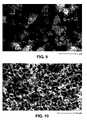
- FIG. 9is a photomicrograph showing the sample has 1.5 ⁇ m macropores in accordance with the present invention.
- FIG. 10is a photomicrograph showing a carbon sample with 2 ⁇ m macropores in accordance with the present invention.
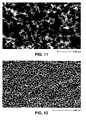
- FIG. 11is a photomicrograph showing a carbon sample with 3 ⁇ m macropores in accordance with the present invention.
- FIG. 12is a photomicrograph showing a carbon sample with 5 ⁇ m macropores in accordance with the present invention.
- FIG. 13is a photomicrograph showing a carbon sample with approximate 10 ⁇ m macropores in accordance with the present invention.
- FIG. 14is a photomicrograph showing a carbon sample with approximate 20 ⁇ m macropores in accordance with the present invention.
- FIG. 15is a photomicrograph showing the secondary porosity of a carbon monolith in accordance with the present invention.
- FIG. 16is a TEM image of the mesopores on a carbon monolith in accordance with the present invention.
- FIG. 17 ais a schematic illustration showing a radial cross-section of a carbon column in accordance with the present invention.
- FIG. 17 bis a schematic illustration showing an axial cross-section of a carbon column in accordance with the present invention.
- a robust, hierarchically porous carbon monolithis characterized by a combination of:
- Graphitized carboncan serve as a highly inert stationary phase that can be used under harsh experimental conditions, e.g., with an extremely acidic or basic solution as the mobile phase in HPLC applications.
- the robust monolithic structurepermits the achievement of a high permeability and fast mass transfer kinetics.
- the columnhas a low backpressure and fast HPLC separations can be performed.
- a carbon monolithic columnis its excellent electrical conductivity. It is possible to modulate retention by adjusting the potential of the carbon surface.
- a carbon monolithic columnis ideal for EMLC because the high electrical conductivity allows a homogeneous surface potential over the entire column and a rapid equilibrium after changes of the applied external electric field.
- the present inventionprovides new liquid chromatography separation patterns, profoundly different from those achieved with known stationary phase materials.
- the present inventionprovides methods of fabricating of a wide variety of carbon monoliths that are especially useful as columns for HPLC and/or EMLC applications. Appropriate modifications to the characteristics of materials used in fabricating the columns allow the achievement of various trade-offs in column efficiency, permeability, rate of separation, column loading capacity, etc.
- the columnis made of a hierarchically porous carbon monolith, which is preferably first clad with a heat shrinkable tube and then encapsulated in a metal or polyether-ether-ketone (PEEK) tube.
- PEEKpolyether-ether-ketone
- a carbon monolith, or “skeleton”is characterized by macropores and mesopores (secondary porosity). The secondary porosity contributes to the surface area which is required to achieve the desired separation.
- Such a hierarchical structureenables fast separation with superior hydraulic properties.
- a robust monolith skeleton wall thicknessmust be at least 100 nm and may be as large as 20 ⁇ m.
- the generally accepted optimal wall thickness for HPLC applicationsis from 200 nm to 5 ⁇ m.
- HPLC applicationsin particular require column material that can sustain pressure from 10 bars to 400 bars.
- Carbon monolithic material of the present inventionis surprisingly robust, and can withstand sustains pressure up to 400 bars without undergoing any structural damage or collapse.
- Fabrication of a robust carbon monolithic column in accordance with the present inventionincludes the following general steps: preparation of a carbon monolith precursor having a porosity-generating fugitive phase; carbonization of the precursor and the removal of the fugitive phase; optional graphitization; and encapsulation to form a chromatographic column.
- a carbon monolith precursoris defined as any material that can be carbonized to form a carbon monolith that can be used for a chromatographic separation.
- the precursormust include a particulate, porosity-generating, fugitive phase which serves as a template for the pores that characterize the final product.
- a carbon monolith precursoris prepared in any desired shape, but is usually rod-shaped to conform to the general shape and size of a liquid chromatography column. Precursors can be prepared by several methods in accordance with the present invention; several examples are described hereinbelow.
- Step 1Silica beads sized from 800 nm to 10 ⁇ m are dispersed in a solvent in a concentration range of 0.1 to 2 g/g using an appropriate dispersing method such as ultrasonic mixing, for example, to form a colloid.
- the solventcan be any polar solvent or solvent mixture. A mixture of ethanol and water is suggested.
- Step 2FeCl 3 is dissolved into the colloid in a concentration range of 0.001 to 0.5 g/g.
- Step 3Resorcinol is dissolved into the colloid in a concentration range of 0.1 to 2.5 g/g.
- Step 4The colloid is agitated to facilitate a reaction to form a resorcinol/Fe(III) complex, illustrated in FIG. 1 .
- Step 5A 5% to 37% solution of formaldehyde in water is cooled to a temperature in the range of about 0° C. to 20° C. and added to the colloid in a concentration range of 0.01 to 2.5 g/g.
- Step 6The colloid is cooled to a temperature in the range of about 0° C. to 20° C. and stirred for a time period of 5 min to 30 min to effect homogeneousness.
- Step 7The colloid is transferred into a mold of desired monolith shape and heated to a temperature in the range of about 50° C. to 95° C. for a time period of 0.5 h to 20 h to effect polymerization of the colloid into a solid monolith, shrinkage of the monolith from the mold wall, and curing of the monolith.
- FIG. 2shows the polymerization reaction.
- Step 8The solid monolith is removed from the mold and the solvent is evaporated therefrom to dryness.
- Step 9The dry monolith is cured at a temperature in the range of about 40° C. to 150° C. for a time period of 3 h to 20 h to effect complete polymerization of the monolith material.
- silica beadswere dispersed in 5 g of an aqueous solution of ethanol (80% ethanol, 20% water) using an ultrasonic mixer. 1.08 g FeCl 3 was then dissolved into the suspension, followed with 2.2 g of resorcinol, dissolved by hand shaking. The colloid solution turned dark immediately after the addition of resorcinol, indicating the formation of a resorcinol/Fe(III) complex. 2.4 g of an ice-cooled, 37% formaldehyde solution in water was introduced into this mixture, in one step, with hand shaking. The mixture was kept in an ice-water bath for 10 minutes with magnetic stirring.
- the mixturewas slowly transferred into 5 mm ID glass tubes which were capped when filled. These tubes were then placed in a 70° C. water bath. The mixture polymerized rapidly into a solid rod inside the glass tube. This rod detached from the tube wall because of the shrinking caused by polymerization.
- the polymer rodwas aged time period of 5 h in the glass tube, which was kept in the hot-water bath.
- the crack-free phenolic resin/silica rodswere removed from the glass tubes by shaking each tube toward its open end.
- the wet rodwas put into the hood for three days, in order to evaporate the solvent. Finally, it was thoroughly dried in a vacuum oven at 80° C., time period of 10 h. The dried rods were further cured at 135° C. for 4 h to ensure complete polymerization.
- This methodis also similar to Method 1, but a suspension of silica beads of two discrete, different particle sizes is used.
- the larger particlescan generally be in a size range of 800 nm to 10 ⁇ m
- the smaller particlescan generally be in a size range of 6 nm to 100 nm
- the population ratio of the larger particles to smaller particlescan generally be in a range of 0.1 to 10.
- the colloidis subject to centrifugation at a sufficient RPM and for a sufficient period of time to effect formation of large particles into a compacted ordered macroporous colloidal array while the small particles remain as a stable suspension in the interstices of the array.
- the porosities of the macropore and mesopore arrayscan be finely adjusted by varying the ratio of the differently sized particles.
- silica beads having a particle size of 5 ⁇ m and 1 g of silica beads having a particle size of 13 nmwere used.
- the colloidwas centrifuged at about 3000 RPM for 30 min. Only the large particles form a compacted ordered colloidal array while the small particles remain as a stable suspension between them. After removal of the supernant, poly-condensation of the colloidal array into a rod was carried out in the centrifuge tube in an oven at 50° C.
- FIG. 3illustrates the fabrication of the precursor monoliths made via methods 1 to 4.
- the colloidal array 30can be silica and/or polystyrene spheres 32 .
- the voids 34are filled with carbon precursor.
- silica spheresare removed by HF or NaOH after carbonization, and polystyrene spheres are removed by thermal decomposition during carbonization, leaving a carbon skeleton.
- TEOStetraethoxylsilane
- P123polyethylene-oxide-propylene-oxide-ethylene-oxide
- 1M HClin a concentration of 0.0001 to 0.04 g/g
- a homogeneous solution of component A, component B, and component Cis induced to perform dual phase separation via reaction.
- the polymerization of component Ainduces a primary phase separation of polymerized component A and component C in micron or submicron scale.
- component Bbecomes enriched in the polymerized phase of component A.
- component Bseparates from component A, resulting in a secondary, nanometer scale phase separation.
- the removal of components B and Cyields the desired hierarchical porous structure of the carbon precursor needed to carry out the present invention.
- FIG. 4shows schematically the principle of the polymerization induced phase separation the ternary system.
- component Ais carbon forming agent
- component Bis a mesopore forming agent
- component Cis a macropore forming agent.
- the three componentsare mixed together, transferred into a mold of desired monolith shape, allowed to settle for a time period of 2 h to 20 h and heated to a temperature in the range of about 40° C. to 50° C. for a time period of 1 h to 72 h to effect curing of the monolith.
- the monolithis then hardened by treating with 20% to 80% sulfuric acid for a time period of 2 h to 10 h.
- Components B and Care then removed by washing the monolith, for example, with copious water.
- the monolithcan then be thoroughly dried. Drying method is not critical, but it is suitable to dry the monolith in a vacuum oven at nominal 100° C.
- Component Ais generally comprised of at least one monomer, and can be selected from at least the following examples: furfuryl alcohol, alkyl substituted furfuryl alcohol, furfuryl aldehyde, alkyl substituted furfuryl alcohol, phenol, alkyl phenol, phenolic alcohol, and alkyl substituted phenolic alcohol, epoxy, and polymers of the aforementioned compositions.
- Component Bcan be comprised of at least one surfactant and/or a low-charring polymer. Nearly all surfactants, including ionic surfactants and nonionic surfactants are contemplated as suitable for use as component B. Polyethylene oxides of various molecular weights, generally in the range of 200 to 100000 Dalton, are suitable candidates for component B.
- Oligomer Ccan be selected from at least the following examples: ethylene glycol, diethylene glycol, triehtylene glycol, tetraenthylene glycol, poly ethylene glycol, oleic acid, propylene glycol, dipropylene glycol, and water.
- Polymerization catalysts, crosslinkers, and/or curing agentscan be added to the mixture.
- Precursors made as described abovecan be carbonized by any conventional carbonization method.
- Carbonizationcan generally comprise heating in an inert environment.
- the particular methodis not critical to the invention, although some methods will be found to be better than others, depending on the desired result.
- soluble fugitive phases and catalystsare removed by dissolution with a solvent that does not harm the carbonized monolith.
- Thermally decomposable and or volatile fugitive phasesare generally removed during carbonization and/or graphitization.
- Carbonized monolithscan then be graphitized by any conventional graphitization method.
- Graphitizationcan generally comprise heating in an inert environment to a temperature exceeding the carbonization temperature. The particular method is not critical to the invention, although some methods will be found to be better than others, depending on the desired result. Graphitization is preferred because it essentially eliminates microporosity (pores ⁇ 18 ⁇ ), but a non-graphitized carbon monolith can be used for some applications. Microporosity can be also blocked by known chemical modification methods.
- FIGS. 5 to 7show the morphologies of carbon monoliths made via colloidal templates.
- Precursor rodswhich were made by Methods 1, 3, and 5 described above were placed into a cylindrical furnace, purged with N2 (45 ml/min). A programmed temperature cycle was applied to the furnace. The temperature was first ramped from 135 to 800° C. at 2.5° C./min and then kept constant at 800° C. for 2 h, to ensure complete carbonization. A second temperature ramp took place from 800° C. to 1250° C. at 10° C./min. The temperature was kept constant at 1250° C. for 1 h. Afterward, the furnace was allowed to cool naturally to ambient temperature. The silica beads and the iron catalyst were removed by washing with a concentrated solution of hydrofluoric acid followed by rinsing with copious amounts of distillated water. The porous carbon rod obtained was thoroughly dried under vacuum at 80° C.
- Porous carbon rods made in accordance with Example VIwere graphitized by high temperature treatment (HTT).
- HHThigh temperature treatment
- the temperature rampswere programmed as a slow ramp from room temperature to 1600° C. at the rate of 5° C./min, and then followed by a rapid ramp to 2400° C. at the rate of 10 to 20° C./min.
- the temperaturewas kept at 2400° C. for 10 to 30 minutes then cooled down to ambient temperature.
- the pore forming agents used in Methods 2, 4, and 6are thermally decomposable and/or volatile. Following carbonization, the carbon monolith does not generally contain any other elements except carbon. Therefore, a single process can be used to carbonize the precursor, remove the fugitive phase (generally via decomposition and/or volatilization), and graphitize the carbon monolith.
- the precursor made via method 6is carbonized and graphitized by heating, preferably in a controlled fashion, from room temperature to graphitization temperature which is in the range of 2100° C. to 2800° C.
- Precursor rods prepared by Methods 2, 4, and 6 described abovewere carbonized and graphitized through a programmed continuous temperature procedure.
- a slow temperature ramp at the rate of 0.1 to 1° C./minwas applied from room temperature to 750° C. to carbonize the polymer rods and followed by a fast temperature ramp at the rate of 2 to 20° C./min to the 2400° C./min and hold at 2400° C. for half an h to graphitize the carbonized rods.
- FIGS. 8 to 14show morphologies of macropores with various sizes. These macropores are the primary porosity of the carbon monoliths. A secondary phase separation results in the secondary porosity on the carbon skeleton.
- FIG. 15shows the secondary porosity on the carbon skeleton.
- FIG. 16shows the mesopores examined by transmission electron microscopy (TEM).
- TEMtransmission electron microscopy
- FIGS. 17 a , 17 bschematically illustrate the cross-section of a carbon column 70 .
- the monolith 72can be clad with an inert cladding 74 , such as polytetrafluoroethylene (PTFE).
- PTFEpolytetrafluoroethylene
- the clad monolithis subsequently coated with a cementing agent such as epoxy cement, and inserted into a structurally robust tube that is suitable for use as a liquid chromatography column.
- Typical tubesare 1 ⁇ 4′′ stainless steel tubing, cut to typical or desired length.
- the columnis complete and ready to be connected to a liquid chromatography system, generally using reduction unions.
- a variety of different columnscan be made by using carbon monoliths of different diameters and lengths. The dimension of the column can thus be varied due to the requirements of applications.
- the carbon rodwas clad in an oven at 340° C. with a section of heat-shrinkable Teflon tubing.
- the encapsulated carbon rodwas then cemented into a precut stainless steel tube, with epoxy cement.
- cladding materialsmay be used to encapsulate the porous carbon monolith in accordance with the present invention.
- the cladding materialscan be thin tubes made of, for example, heat-shrinkable PTFE, PEEK, fluorinated ethylene propylene (FEP), perfluoroalkoxy (PFA), or mixtures of these polymers. They are available in all necessary sizes and grades. Some are resistant to the same chemicals as the carbon monoliths.
- FEPfluorinated ethylene propylene
- PFAperfluoroalkoxy
- FIGS. 17 a , 17 bshow schematically, not to scale, a chromatography column 70 including carbon monolith 72 , cladding 74 , and tube 76 .
- the monolithic carbon columncan be made into any dimensions with any desired shape and dimensions in accordance with the present invention.
- contemplated shapesinclude, but are not limited to rod, disk, tube, annular, angular, helical, coil, etc.
- the monolithic carbon columncan be subject to chemical treatment of the carbon monolith with functionalities for the enhancement of the separation effect.
- chemical treatmentinclude, but are not limited to: chemically oxidizing the carbon surface; chemically grafting ligands and/or organic chains to the carbon surface; electrochemically reducing aryl diazonium salts on the carbon surface; electrochemically oxidizing alkylamines on the carbon surface; electrochemically oxidizing arylacetates on the carbon surface; and electrochemically oxidizing alcohols on the carbon surface.
- the monolithic carbon columncan be subject to physical treatment of the carbon monolith with functionalities for the enhancement of the separation effect.
- physical treatmentinclude, but are not limited to physical absorption of functional molecules such as surfactants, macromolecules, crown ether, porphyrin, and other compositions that are generally used for the purpose of enhancing chromatographic separations.
- the monolithic carbon columncan be used as sorbents for solid phase extraction processes.
- the monolithic carbon columncan be used for gas chromatography and any other type of analytical chromatographic separation.
- the monolithic carbon columncan be used as catalyst bed.
- catalyst particlescan be chemically or electrochemically deposited in the pores of the carbon monolithic column.
- Various catalyst particlescan be used to catalyze various reactions.
- the monolithic carbon columncan be used as porous electrode for any electrochemical system, especially those that require high electrode surface area.
- the carbon monolithic columncan also be used as a flow-through electrode for continuous electrochemical processes.
- Carbon monolithic columns made in accordance with the present inventionhave an extremely high resistance to aggressive chemicals. They can be used with solutions having any pH (from below 0 to above 14, if needed), with nearly any solvent or solvent mixtures, and at any practical temperature.
- the carbon monolithic columnscan generally be attacked only by concentrated hydrogen peroxide, solutions of organic peroxides and of ozone, and are free from many of the disadvantages of silica- or polymer-based columns.
- Carbon monolithic columns made in accordance with the present inventionexhibit a high electrical conductivity and are electrically homogeneous. This makes them ideal for EMLC.
- the present inventioncan be, among other applications, used as the working electrode of EMLC columns.
- the columnmay be configured as a 2-electrode or a 3-electrode EMLC column.
- the counter-electrode and of the reference electrodecould be placed in the column, upstream, or downstream of the column.
Landscapes
- Chemical & Material Sciences (AREA)
- Organic Chemistry (AREA)
- Analytical Chemistry (AREA)
- Chemical Kinetics & Catalysis (AREA)
- Engineering & Computer Science (AREA)
- Ceramic Engineering (AREA)
- Inorganic Chemistry (AREA)
- Nanotechnology (AREA)
- Materials Engineering (AREA)
- Structural Engineering (AREA)
- Carbon And Carbon Compounds (AREA)
- Solid-Sorbent Or Filter-Aiding Compositions (AREA)
Abstract
Description
- encapsulating the porous carbon monolith to form a chromatographic column.
- 1. Macropores having a size in the range of 0.05 μm to 100 μm, preferably in the range of 0.1 μm to 50 μm, more preferably in the range of 0.8 μm to 10 μm;
- 2. Mesopores having a size range of 18 Å to 50 nm, preferably in the range of 0.5 nm to 40 nm, more preferably in the range of 5 nm to 30 nm; and
- 3. A skeleton size (monolith wall thickness) in the range of 100 nm to 20 μm, preferably in the range of 200 nm to 10 μm, more preferably in the range of 400 nm to 1 μm.
Claims (26)
Priority Applications (5)
| Application Number | Priority Date | Filing Date | Title |
|---|---|---|---|
| US10/770,734US7449165B2 (en) | 2004-02-03 | 2004-02-03 | Robust carbon monolith having hierarchical porosity |
| PCT/US2005/002786WO2005075379A2 (en) | 2004-02-03 | 2005-02-01 | Robust carbon monolith having hierarchical porosity |
| US12/145,927US7892516B2 (en) | 2004-02-03 | 2008-06-25 | Robust carbon monolith having hierarchical porosity |
| US13/011,554US8366979B2 (en) | 2004-02-03 | 2011-01-21 | Robust carbon monolith having hierarchical porosity |
| US13/741,745US8628705B2 (en) | 2004-02-03 | 2013-01-15 | Robust carbon monolith having hierarchical porosity |
Applications Claiming Priority (1)
| Application Number | Priority Date | Filing Date | Title |
|---|---|---|---|
| US10/770,734US7449165B2 (en) | 2004-02-03 | 2004-02-03 | Robust carbon monolith having hierarchical porosity |
Related Child Applications (1)
| Application Number | Title | Priority Date | Filing Date |
|---|---|---|---|
| US12/145,927ContinuationUS7892516B2 (en) | 2004-02-03 | 2008-06-25 | Robust carbon monolith having hierarchical porosity |
Publications (2)
| Publication Number | Publication Date |
|---|---|
| US20050169829A1 US20050169829A1 (en) | 2005-08-04 |
| US7449165B2true US7449165B2 (en) | 2008-11-11 |
Family
ID=34808373
Family Applications (4)
| Application Number | Title | Priority Date | Filing Date |
|---|---|---|---|
| US10/770,734Expired - Fee RelatedUS7449165B2 (en) | 2004-02-03 | 2004-02-03 | Robust carbon monolith having hierarchical porosity |
| US12/145,927Expired - Fee RelatedUS7892516B2 (en) | 2004-02-03 | 2008-06-25 | Robust carbon monolith having hierarchical porosity |
| US13/011,554Expired - LifetimeUS8366979B2 (en) | 2004-02-03 | 2011-01-21 | Robust carbon monolith having hierarchical porosity |
| US13/741,745Expired - LifetimeUS8628705B2 (en) | 2004-02-03 | 2013-01-15 | Robust carbon monolith having hierarchical porosity |
Family Applications After (3)
| Application Number | Title | Priority Date | Filing Date |
|---|---|---|---|
| US12/145,927Expired - Fee RelatedUS7892516B2 (en) | 2004-02-03 | 2008-06-25 | Robust carbon monolith having hierarchical porosity |
| US13/011,554Expired - LifetimeUS8366979B2 (en) | 2004-02-03 | 2011-01-21 | Robust carbon monolith having hierarchical porosity |
| US13/741,745Expired - LifetimeUS8628705B2 (en) | 2004-02-03 | 2013-01-15 | Robust carbon monolith having hierarchical porosity |
Country Status (2)
| Country | Link |
|---|---|
| US (4) | US7449165B2 (en) |
| WO (1) | WO2005075379A2 (en) |
Cited By (8)
| Publication number | Priority date | Publication date | Assignee | Title |
|---|---|---|---|---|
| US20110140296A1 (en)* | 2004-02-03 | 2011-06-16 | Ut-Battelle, Llc | Robust carbon monolith having hierarchical porosity |
| WO2014062793A1 (en) | 2012-10-16 | 2014-04-24 | The Board Of Trustees Of The University Of Alabama | Catalysis by metal nanoparticles dispersed within a hierarchically porous carbon material |
| US8828533B2 (en) | 2012-01-12 | 2014-09-09 | Ut-Battelle, Llc | Mesoporous carbon materials |
| US8865351B2 (en) | 2011-03-14 | 2014-10-21 | Ut-Battelle, Llc | Carbon composition with hierarchical porosity, and methods of preparation |
| US9212062B2 (en) | 2011-07-27 | 2015-12-15 | Heraeus Quarzglas Gmbh & Co. Kg | Porous carbon product and method for producing an electrode for a rechargeable lithium battery |
| US9249241B2 (en) | 2013-03-27 | 2016-02-02 | Ut-Battelle, Llc | Surface-functionalized mesoporous carbon materials |
| US10195587B2 (en) | 2016-03-04 | 2019-02-05 | The Board Of Trustees Of The University Of Alabama | Synthesis of hierarchically porous monoliths by a co-gelation method |
| US10702852B2 (en) | 2016-06-16 | 2020-07-07 | Ut-Battelle, Llc | Amidoxime-functionalized materials and their use in extracting metal ions from liquid solutions |
Families Citing this family (57)
| Publication number | Priority date | Publication date | Assignee | Title |
|---|---|---|---|---|
| US8002880B2 (en) | 2002-12-10 | 2011-08-23 | Advanced Technology Materials, Inc. | Gas storage and dispensing system with monolithic carbon adsorbent |
| US20060140843A1 (en)* | 2004-12-23 | 2006-06-29 | In-Kyung Sung | Macroporous structures for heterogeneous catalyst support |
| US8247072B2 (en) | 2006-02-14 | 2012-08-21 | Eastman Chemical Company | Resol beads, methods of making them and methods of using them |
| US20070207917A1 (en)* | 2006-02-14 | 2007-09-06 | Chester Wayne Sink | Activated carbon monoliths and methods of making them |
| WO2007104798A2 (en)* | 2006-03-15 | 2007-09-20 | University Of York | Mesoporous carbonaceous materials, preparation and use thereof |
| CN101610836B (en)* | 2006-05-25 | 2012-08-08 | 通用汽车环球科技运作公司 | Carbon and carbon composites with highly ordered mesosize pores |
| US8164881B2 (en)* | 2006-05-31 | 2012-04-24 | Max-Planck-Gesellschaft Zur Foerderung Der Wissenschaften E.V. | Porous carbon electrode with conductive polymer coating |
| KR20090032050A (en)* | 2006-05-31 | 2009-03-31 | 메르크 파텐트 게엠베하 | Method of Making Porous Carbon Castings |
| JP2008107176A (en)* | 2006-10-25 | 2008-05-08 | Hitachi High-Technologies Corp | Separation column and liquid chromatograph using the same |
| US7872563B2 (en) | 2007-04-09 | 2011-01-18 | The Board Of Trustees Of The University Of Illinois | Variably porous structures |
| BRPI0814731A2 (en)* | 2007-06-22 | 2015-02-24 | Advanced Tech Materials | COMPONENTS FOR SOLAR ADSORTION COOLING SYSTEM AND METHOD FOR MAKING THIS CROSS REFERENCE COMPONENT FOR RELATED APPLICATIONS |
| GB0718263D0 (en)* | 2007-09-19 | 2007-10-31 | Univ York | Polysaccharide derived mesoporous materials |
| US7976587B2 (en)* | 2007-10-31 | 2011-07-12 | Corning Incorporated | High energy density ultracapacitor |
| CN101580246B (en)* | 2009-05-21 | 2012-06-27 | 中国科学院上海硅酸盐研究所 | Porous zeotile sphere material and preparation method thereof |
| DE102010005954B4 (en) | 2010-01-27 | 2020-11-19 | Heraeus Quarzglas Gmbh & Co. Kg | Porous carbon product |
| CN101944396B (en)* | 2010-07-29 | 2013-01-02 | 兰州理工大学 | Method for preparing porous mold charcoal/metal oxide composite material for super capacitor electrode |
| JP5911240B2 (en)* | 2010-10-04 | 2016-04-27 | キヤノン株式会社 | Porous glass, manufacturing method thereof, optical member, and imaging apparatus |
| DE102010049249A1 (en) | 2010-10-25 | 2012-04-26 | Heraeus Quarzglas Gmbh & Co. Kg | Porous carbon product, process for its production and use |
| EP2660198A4 (en)* | 2010-12-29 | 2018-03-28 | Ocean's King Lighting Science&Technology Co., Ltd. | Porous graphene material and preparation method and uses as electrode material thereof |
| US8679231B2 (en) | 2011-01-19 | 2014-03-25 | Advanced Technology Materials, Inc. | PVDF pyrolyzate adsorbent and gas storage and dispensing system utilizing same |
| US8574340B2 (en) | 2011-02-27 | 2013-11-05 | Board Of Trustees Of The University Of Alabama | Methods for preparing and using metal and/or metal oxide porous materials |
| DE102011013075B4 (en) | 2011-03-04 | 2019-03-28 | Heraeus Quarzglas Gmbh & Co. Kg | Process for producing a porous carbon product |
| TWI542537B (en)* | 2011-03-09 | 2016-07-21 | 東洋炭素股份有限公司 | Porous carbon and a method for producing the same |
| DE102011014875B3 (en)* | 2011-03-23 | 2012-04-19 | Heraeus Quarzglas Gmbh & Co. Kg | Process for the production of porous granules of inorganic material and their use |
| JP5751582B2 (en)* | 2011-06-03 | 2015-07-22 | 国立研究開発法人物質・材料研究機構 | Method for producing porous carbon membrane |
| CN103170161B (en)* | 2011-12-22 | 2014-09-24 | 中国科学院大连化学物理研究所 | A kind of preparation method of organic-inorganic hybrid monolithic column |
| WO2013120011A1 (en) | 2012-02-09 | 2013-08-15 | Energ2 Technologies, Inc. | Preparation of polymeric resins and carbon materials |
| CN103855412B (en)* | 2012-11-28 | 2016-07-13 | 中国科学院大连化学物理研究所 | Porous carbon materials for positive electrodes of lithium-air batteries |
| CN105190966B (en) | 2012-12-19 | 2018-06-12 | 锡安能量公司 | Electrode structure and manufacturing method thereof |
| CN110112377A (en) | 2013-03-14 | 2019-08-09 | 14族科技公司 | The complex carbon material of electrochemical modification agent comprising lithium alloyage |
| DE102013106114B4 (en) | 2013-06-12 | 2019-05-09 | Heraeus Quarzglas Gmbh & Co. Kg | Lithium-ion cell for a secondary battery |
| DE102013110453A1 (en) | 2013-09-20 | 2015-03-26 | Heraeus Quarzglas Gmbh & Co. Kg | Process for producing a porous carbon product |
| US10195583B2 (en) | 2013-11-05 | 2019-02-05 | Group 14 Technologies, Inc. | Carbon-based compositions with highly efficient volumetric gas sorption |
| JP2015102351A (en)* | 2013-11-21 | 2015-06-04 | 公立大学法人首都大学東京 | Column packing, column, and column system |
| EP3143051B1 (en) | 2014-03-14 | 2024-12-04 | Group14 Technologies, Inc. | Novel methods for sol-gel polymerization in absence of solvent and creation of tunable carbon structure from same |
| IN2014DE01015A (en) | 2014-04-10 | 2015-10-16 | Indian Inst Technology Kanpur | |
| JP2017515277A (en) | 2014-05-01 | 2017-06-08 | ビーエイエスエフ・ソシエタス・エウロパエアBasf Se | Electrode manufacturing method and related system and article |
| EP3034484A1 (en)* | 2014-12-17 | 2016-06-22 | Leibniz-Institut für Polymerforschung Dresden e.V. | Cathodes for Li-S batteries |
| JP6650756B2 (en)* | 2015-06-10 | 2020-02-19 | アルプスアルパイン株式会社 | Channel unit |
| EP3109550B1 (en) | 2015-06-19 | 2019-09-04 | Rolls-Royce Corporation | Turbine cooled cooling air flowing through a tubular arrangement |
| CN107708851B (en) | 2015-06-30 | 2021-12-21 | 株式会社Sng | Reaction method for reaction by contact with granular porous body |
| US10763501B2 (en) | 2015-08-14 | 2020-09-01 | Group14 Technologies, Inc. | Nano-featured porous silicon materials |
| EP4512791A3 (en) | 2015-08-28 | 2025-09-03 | Group14 Technologies, Inc. | Novel materials with extremely durable intercalation of lithium and manufacturing methods thereof |
| US10434870B2 (en) | 2016-05-11 | 2019-10-08 | GM Global Technology Operations LLC | Adsorption storage tank for natural gas |
| KR101826957B1 (en) | 2016-05-19 | 2018-02-07 | 숭실대학교 산학협력단 | Preparing method of transition metal-nitrogen doped porous carbon catalyst using amino acid |
| KR102571014B1 (en) | 2017-03-09 | 2023-08-25 | 그룹14 테크놀로지스, 인코포레이티드 | Degradation of silicon-containing precursors on porous scaffold materials |
| US10381170B2 (en) | 2017-03-29 | 2019-08-13 | GM Global Technology Operations LLC | Microporous and hierarchical porous carbon |
| KR101972668B1 (en)* | 2017-11-10 | 2019-04-25 | 에스케이씨코오롱피아이 주식회사 | Graphite Sheet Having Excellent Thermal Conductivity and Method for Preparing The Same |
| CN111868126A (en)* | 2018-01-24 | 2020-10-30 | 巴斯夫欧洲公司 | Method for preparing carbon material |
| WO2019159608A1 (en)* | 2018-02-14 | 2019-08-22 | 日本碍子株式会社 | Titania porous body and method for producing same |
| US20200071168A1 (en) | 2018-09-04 | 2020-03-05 | Carnegie Mellon University | Aqueous route to nitrogen-doped mesoporous carbons |
| US12023603B2 (en)* | 2019-09-19 | 2024-07-02 | University Of Utah Research Foundation | Two-electrode configuration for separations based on electrosorption in electrochemically modulated liquid chromatography (EMLC) |
| ES2829958B2 (en)* | 2019-12-02 | 2021-12-21 | Consejo Superior Investigacion | PROCEDURE FOR OBTAINING INTEGRAL CARBON MONOLITHS AND OBTAINED CARBON MONOLITHS |
| US11174167B1 (en) | 2020-08-18 | 2021-11-16 | Group14 Technologies, Inc. | Silicon carbon composites comprising ultra low Z |
| US11335903B2 (en) | 2020-08-18 | 2022-05-17 | Group14 Technologies, Inc. | Highly efficient manufacturing of silicon-carbon composites materials comprising ultra low z |
| JP2023544717A (en) | 2020-09-30 | 2023-10-25 | グループ14・テクノロジーズ・インコーポレイテッド | Passivation method for controlling oxygen content and reactivity of silicon-carbon composites |
| WO2022093989A1 (en)* | 2020-10-27 | 2022-05-05 | Mchref Yehia | Methods and systems for isomeric separation using mesoporous graphitized carbon |
Citations (4)
| Publication number | Priority date | Publication date | Assignee | Title |
|---|---|---|---|---|
| US5902562A (en)* | 1995-12-21 | 1999-05-11 | Sandia Corporation | Method for the preparation of high surface area high permeability carbons |
| US6024899A (en)* | 1998-07-20 | 2000-02-15 | Corning Incorporated | Method of making mesoporous carbon using pore formers |
| US6515845B1 (en)* | 2000-02-22 | 2003-02-04 | Fincell Co., Ltd. | Method for preparing nanoporous carbon materials and electric double-layer capacitors using them |
| US20050169829A1 (en) | 2004-02-03 | 2005-08-04 | Sheng Dai | Robust carbon monolith having hierarchical porosity |
Family Cites Families (12)
| Publication number | Priority date | Publication date | Assignee | Title |
|---|---|---|---|---|
| SU1706690A1 (en)* | 1988-04-19 | 1992-01-23 | Всесоюзный Научно-Исследовательский Институт Технического Углерода | Porous carbon material |
| JP2733191B2 (en)* | 1993-09-27 | 1998-03-30 | 工業技術院長 | Ferromagnetic carbon material and method for producing the same |
| US5902563A (en)* | 1997-10-30 | 1999-05-11 | Pl-Limited | RF/VHF plasma diamond growth method and apparatus and materials produced therein |
| US6261469B1 (en)* | 1998-10-13 | 2001-07-17 | Honeywell International Inc. | Three dimensionally periodic structural assemblies on nanometer and longer scales |
| KR100307692B1 (en)* | 1999-06-02 | 2001-09-24 | 윤덕용 | Carbon molecular sieve materials, methods for preparing the same and uses thereof |
| US6297293B1 (en) | 1999-09-15 | 2001-10-02 | Tda Research, Inc. | Mesoporous carbons and polymers |
| DE10028447A1 (en)* | 2000-06-14 | 2001-12-20 | Merck Patent Gmbh | Monolithic porous molded article production, used for chromatographic separation of substances, comprises repeated filling of gel mold with monomer sol, polymerization and aging gel |
| JP2004534713A (en)* | 2001-07-13 | 2004-11-18 | ケント ステイト ユニバーシティ | Imprinted mesoporous carbon and method for producing the same |
| US7074880B2 (en)* | 2002-07-22 | 2006-07-11 | Aspen Aerogels, Inc. | Polyimide aerogels, carbon aerogels, and metal carbide aerogels and methods of making same |
| KR100489284B1 (en)* | 2002-11-13 | 2005-05-11 | 삼성전자주식회사 | A Method for preparing Nanoporous Carbons with enhanced mechanical strength and the Nanoporous Carbons using the method |
| KR100474854B1 (en)* | 2003-02-13 | 2005-03-10 | 삼성에스디아이 주식회사 | Carbon molecular sieve and preparation method thereof |
| US8164881B2 (en)* | 2006-05-31 | 2012-04-24 | Max-Planck-Gesellschaft Zur Foerderung Der Wissenschaften E.V. | Porous carbon electrode with conductive polymer coating |
- 2004
- 2004-02-03USUS10/770,734patent/US7449165B2/ennot_activeExpired - Fee Related
- 2005
- 2005-02-01WOPCT/US2005/002786patent/WO2005075379A2/enactiveApplication Filing
- 2008
- 2008-06-25USUS12/145,927patent/US7892516B2/ennot_activeExpired - Fee Related
- 2011
- 2011-01-21USUS13/011,554patent/US8366979B2/ennot_activeExpired - Lifetime
- 2013
- 2013-01-15USUS13/741,745patent/US8628705B2/ennot_activeExpired - Lifetime
Patent Citations (4)
| Publication number | Priority date | Publication date | Assignee | Title |
|---|---|---|---|---|
| US5902562A (en)* | 1995-12-21 | 1999-05-11 | Sandia Corporation | Method for the preparation of high surface area high permeability carbons |
| US6024899A (en)* | 1998-07-20 | 2000-02-15 | Corning Incorporated | Method of making mesoporous carbon using pore formers |
| US6515845B1 (en)* | 2000-02-22 | 2003-02-04 | Fincell Co., Ltd. | Method for preparing nanoporous carbon materials and electric double-layer capacitors using them |
| US20050169829A1 (en) | 2004-02-03 | 2005-08-04 | Sheng Dai | Robust carbon monolith having hierarchical porosity |
Non-Patent Citations (4)
| Title |
|---|
| Gzil, Piotr et al., "A Computational Study of the Porosity Effects in Silica Monolithic Columns," J. Sep. Sci., 2004, p. 887-896, vol. 27. |
| Liang, Chengdu, et al., "A Graphitized-Carbon Monolithic Column," Anal. Chemistry, 2003, p. 4904-4912, vol. 75. |
| Polarz, S., et al., "Hierarchical Porous Carbon Structures from Cellulose Acetate Fibers", Chem. Mater., 2002, 14, 2940-2945. |
| Taguchi, Akira, et al., "Carbon Monoliths Possessing a Hierarchical, Fully Interconnected Porosity", Adv. Mater., 2003, 15, No. 14, 1209-1211. |
Cited By (15)
| Publication number | Priority date | Publication date | Assignee | Title |
|---|---|---|---|---|
| US8366979B2 (en)* | 2004-02-03 | 2013-02-05 | Ut-Battelle, Llc | Robust carbon monolith having hierarchical porosity |
| US8628705B2 (en) | 2004-02-03 | 2014-01-14 | Ut-Battelle, Llc | Robust carbon monolith having hierarchical porosity |
| US20110140296A1 (en)* | 2004-02-03 | 2011-06-16 | Ut-Battelle, Llc | Robust carbon monolith having hierarchical porosity |
| US10023480B2 (en) | 2011-03-14 | 2018-07-17 | Ut-Battelle, Llc | Carbon composition with hierarchical porosity, and methods of preparation |
| US8865351B2 (en) | 2011-03-14 | 2014-10-21 | Ut-Battelle, Llc | Carbon composition with hierarchical porosity, and methods of preparation |
| US10626028B2 (en) | 2011-03-14 | 2020-04-21 | Ut-Battelle, Llc | Carbon composition with hierarchical porosity, and methods of preparation |
| US9212062B2 (en) | 2011-07-27 | 2015-12-15 | Heraeus Quarzglas Gmbh & Co. Kg | Porous carbon product and method for producing an electrode for a rechargeable lithium battery |
| US8828533B2 (en) | 2012-01-12 | 2014-09-09 | Ut-Battelle, Llc | Mesoporous carbon materials |
| WO2014062793A1 (en) | 2012-10-16 | 2014-04-24 | The Board Of Trustees Of The University Of Alabama | Catalysis by metal nanoparticles dispersed within a hierarchically porous carbon material |
| US9669388B2 (en) | 2012-10-16 | 2017-06-06 | The Board Trustees of The University of Alabama | Catalysis by metal nanoparticles dispersed within a hierarchically porous carbon material |
| US9233366B2 (en) | 2012-10-16 | 2016-01-12 | Board Of Trustees Of The University Of Alabama | Catalysis by metal nanoparticles dispersed within a hierarchically porous carbon material |
| US9249241B2 (en) | 2013-03-27 | 2016-02-02 | Ut-Battelle, Llc | Surface-functionalized mesoporous carbon materials |
| US10195587B2 (en) | 2016-03-04 | 2019-02-05 | The Board Of Trustees Of The University Of Alabama | Synthesis of hierarchically porous monoliths by a co-gelation method |
| US10702852B2 (en) | 2016-06-16 | 2020-07-07 | Ut-Battelle, Llc | Amidoxime-functionalized materials and their use in extracting metal ions from liquid solutions |
| US11247191B2 (en) | 2016-06-16 | 2022-02-15 | Ut-Battelle, Llc | Amidoxime-functionalized materials and their use in extracting metal ions from liquid solutions |
Also Published As
| Publication number | Publication date |
|---|---|
| WO2005075379A3 (en) | 2006-01-26 |
| US8628705B2 (en) | 2014-01-14 |
| US20110140296A1 (en) | 2011-06-16 |
| US7892516B2 (en) | 2011-02-22 |
| US20090044606A1 (en) | 2009-02-19 |
| WO2005075379A2 (en) | 2005-08-18 |
| US8366979B2 (en) | 2013-02-05 |
| US20130129920A1 (en) | 2013-05-23 |
| US20050169829A1 (en) | 2005-08-04 |
Similar Documents
| Publication | Publication Date | Title |
|---|---|---|
| US7449165B2 (en) | Robust carbon monolith having hierarchical porosity | |
| Yu et al. | Polymerization under hypersaline conditions: a robust route to phenolic polymer‐derived carbon aerogels | |
| Mariyam et al. | Efficient batch and Fixed-Bed sequestration of a basic dye using a novel variant of ordered mesoporous carbon as adsorbent | |
| Al‐Muhtaseb et al. | Preparation and properties of resorcinol–formaldehyde organic and carbon gels | |
| US6297293B1 (en) | Mesoporous carbons and polymers | |
| US5508341A (en) | Organic aerogel microspheres and fabrication method therefor | |
| Che et al. | Synthesis of Large‐Pore Ia ̄3 d Mesoporous Silica and Its Tubelike Carbon Replica | |
| US7326396B2 (en) | Method for preparing nanoporous carbons with enhanced mechanical strength and the nanoporous carbons prepared by the method | |
| Ongkudon et al. | Challenges and strategies in the preparation of large‐volume polymer‐based monolithic chromatography adsorbents | |
| KR20010082910A (en) | Method for Preparing Nanoporous Carbon Materials using Inorganic Templates | |
| JP2010001213A (en) | Material for chromatography, and method for production of the material | |
| US7167354B2 (en) | Mesoporous carbons and polymers from hydroxylated benzenes | |
| CN115624922B (en) | Amidoxime functionalized covalent organic framework and graphene oxide hybrid aerogel as well as preparation method and application thereof | |
| KR101393493B1 (en) | Globular carbon particle, and preparing method of the same | |
| Rojas-Cervantes | Some strategies to lower the production cost of carbon gels | |
| WO2017098314A1 (en) | Method of obtaining mobile magnetic composite adsorbents | |
| US11325831B2 (en) | Carbon nanotube foams with controllable architecture and methods | |
| Santiago Cordoba et al. | Aerobijels: Ultralight carbon monoliths from cocontinuous emulsions | |
| Xia et al. | Wood-derived carbons with hierarchical porous structures and monolithic shapes prepared by biological-template and self-assembly strategies | |
| JP2007016249A (en) | Organic, open cell foam materials | |
| Zhao et al. | Nitrogen, sulfur co‐doped porous carbon via high internal phase emulsion template and its potential application as the electrode of high‐performance supercapacitor | |
| Eltmimi et al. | Preparation, characterisation and modification of carbon‐based monolithic rods for chromatographic applications | |
| Duffy et al. | Hierarchical porous graphitic carbon monoliths with detonation nanodiamonds: synthesis, characterisation and adsorptive properties | |
| JP2024502704A (en) | Method for producing porous carbon structures with increased surface area and total pore volume, and porous carbon structures produced using the same | |
| KR101281139B1 (en) | Method for making the silica nano tube and method for analyzing it |
Legal Events
| Date | Code | Title | Description |
|---|---|---|---|
| AS | Assignment | Owner name:UT-BATTELLE, LLC, TENNESSEE Free format text:ASSIGNMENT OF ASSIGNORS INTEREST;ASSIGNOR:DAI, SHENG;REEL/FRAME:014963/0541 Effective date:20040203 Owner name:UNIVERSITY OF TENNESSEE RESEARCH FOUNDATION, TENNE Free format text:ASSIGNMENT OF ASSIGNORS INTEREST;ASSIGNORS:GUIOCHON, GEORGES A.;LIANG, CHENGDU;REEL/FRAME:014985/0711 Effective date:20040203 | |
| AS | Assignment | Owner name:ENERGY, U.S. DEPARTMENT OF, DISTRICT OF COLUMBIA Free format text:CONFIRMATORY LICENSE;ASSIGNOR:UT-BATTELLE, LLLC;REEL/FRAME:014657/0030 Effective date:20040507 | |
| STCF | Information on status: patent grant | Free format text:PATENTED CASE | |
| FEPP | Fee payment procedure | Free format text:PAYOR NUMBER ASSIGNED (ORIGINAL EVENT CODE: ASPN); ENTITY STATUS OF PATENT OWNER: SMALL ENTITY | |
| FPAY | Fee payment | Year of fee payment:4 | |
| FPAY | Fee payment | Year of fee payment:8 | |
| FEPP | Fee payment procedure | Free format text:MAINTENANCE FEE REMINDER MAILED (ORIGINAL EVENT CODE: REM.); ENTITY STATUS OF PATENT OWNER: SMALL ENTITY | |
| LAPS | Lapse for failure to pay maintenance fees | Free format text:PATENT EXPIRED FOR FAILURE TO PAY MAINTENANCE FEES (ORIGINAL EVENT CODE: EXP.); ENTITY STATUS OF PATENT OWNER: SMALL ENTITY | |
| STCH | Information on status: patent discontinuation | Free format text:PATENT EXPIRED DUE TO NONPAYMENT OF MAINTENANCE FEES UNDER 37 CFR 1.362 | |
| FP | Lapsed due to failure to pay maintenance fee | Effective date:20201111 |