US7448770B2 - Replacement illumination device for a miniature flashlight bulb - Google Patents
Replacement illumination device for a miniature flashlight bulbDownload PDFInfo
- Publication number
- US7448770B2 US7448770B2US11/831,791US83179107AUS7448770B2US 7448770 B2US7448770 B2US 7448770B2US 83179107 AUS83179107 AUS 83179107AUS 7448770 B2US7448770 B2US 7448770B2
- Authority
- US
- United States
- Prior art keywords
- flashlight
- light
- incandescent
- light source
- reflector
- Prior art date
- Legal status (The legal status is an assumption and is not a legal conclusion. Google has not performed a legal analysis and makes no representation as to the accuracy of the status listed.)
- Expired - Fee Related
Links
- 238000005286illuminationMethods0.000titleclaimsdescription7
- 239000007787solidSubstances0.000claimsabstractdescription19
- 238000000034methodMethods0.000claimsabstractdescription9
- CPLXHLVBOLITMK-UHFFFAOYSA-NMagnesium oxideChemical compound[Mg]=OCPLXHLVBOLITMK-UHFFFAOYSA-N0.000abstractdescription6
- 238000009420retrofittingMethods0.000abstractdescription4
- 230000001681protective effectEffects0.000description5
- 239000003990capacitorSubstances0.000description4
- 238000010586diagramMethods0.000description4
- 239000000463materialSubstances0.000description4
- 238000013461designMethods0.000description3
- 230000005855radiationEffects0.000description3
- 239000004020conductorSubstances0.000description2
- 238000004382pottingMethods0.000description2
- 230000001105regulatory effectEffects0.000description2
- 239000004065semiconductorSubstances0.000description2
- 238000012935AveragingMethods0.000description1
- 239000004593EpoxySubstances0.000description1
- 210000004460N cellAnatomy0.000description1
- XAGFODPZIPBFFR-UHFFFAOYSA-NaluminiumChemical compound[Al]XAGFODPZIPBFFR-UHFFFAOYSA-N0.000description1
- 229910052782aluminiumInorganic materials0.000description1
- 238000013459approachMethods0.000description1
- 210000004027cellAnatomy0.000description1
- 239000003086colorantSubstances0.000description1
- 238000004519manufacturing processMethods0.000description1
- 230000013011matingEffects0.000description1
- 230000003287optical effectEffects0.000description1
- 229920003023plasticPolymers0.000description1
- 238000012546transferMethods0.000description1
Images


Classifications
- F—MECHANICAL ENGINEERING; LIGHTING; HEATING; WEAPONS; BLASTING
- F21—LIGHTING
- F21V—FUNCTIONAL FEATURES OR DETAILS OF LIGHTING DEVICES OR SYSTEMS THEREOF; STRUCTURAL COMBINATIONS OF LIGHTING DEVICES WITH OTHER ARTICLES, NOT OTHERWISE PROVIDED FOR
- F21V23/00—Arrangement of electric circuit elements in or on lighting devices
- F21V23/003—Arrangement of electric circuit elements in or on lighting devices the elements being electronics drivers or controllers for operating the light source, e.g. for a LED array
- F21V23/004—Arrangement of electric circuit elements in or on lighting devices the elements being electronics drivers or controllers for operating the light source, e.g. for a LED array arranged on a substrate, e.g. a printed circuit board
- F21V23/005—Arrangement of electric circuit elements in or on lighting devices the elements being electronics drivers or controllers for operating the light source, e.g. for a LED array arranged on a substrate, e.g. a printed circuit board the substrate is supporting also the light source
- F—MECHANICAL ENGINEERING; LIGHTING; HEATING; WEAPONS; BLASTING
- F21—LIGHTING
- F21K—NON-ELECTRIC LIGHT SOURCES USING LUMINESCENCE; LIGHT SOURCES USING ELECTROCHEMILUMINESCENCE; LIGHT SOURCES USING CHARGES OF COMBUSTIBLE MATERIAL; LIGHT SOURCES USING SEMICONDUCTOR DEVICES AS LIGHT-GENERATING ELEMENTS; LIGHT SOURCES NOT OTHERWISE PROVIDED FOR
- F21K9/00—Light sources using semiconductor devices as light-generating elements, e.g. using light-emitting diodes [LED] or lasers
- F21K9/20—Light sources comprising attachment means
- F21K9/23—Retrofit light sources for lighting devices with a single fitting for each light source, e.g. for substitution of incandescent lamps with bayonet or threaded fittings
- F21K9/238—Arrangement or mounting of circuit elements integrated in the light source
- F—MECHANICAL ENGINEERING; LIGHTING; HEATING; WEAPONS; BLASTING
- F21—LIGHTING
- F21L—LIGHTING DEVICES OR SYSTEMS THEREOF, BEING PORTABLE OR SPECIALLY ADAPTED FOR TRANSPORTATION
- F21L4/00—Electric lighting devices with self-contained electric batteries or cells
- F21L4/02—Electric lighting devices with self-contained electric batteries or cells characterised by the provision of two or more light sources
- F—MECHANICAL ENGINEERING; LIGHTING; HEATING; WEAPONS; BLASTING
- F21—LIGHTING
- F21V—FUNCTIONAL FEATURES OR DETAILS OF LIGHTING DEVICES OR SYSTEMS THEREOF; STRUCTURAL COMBINATIONS OF LIGHTING DEVICES WITH OTHER ARTICLES, NOT OTHERWISE PROVIDED FOR
- F21V23/00—Arrangement of electric circuit elements in or on lighting devices
- F21V23/06—Arrangement of electric circuit elements in or on lighting devices the elements being coupling devices, e.g. connectors
- F—MECHANICAL ENGINEERING; LIGHTING; HEATING; WEAPONS; BLASTING
- F21—LIGHTING
- F21V—FUNCTIONAL FEATURES OR DETAILS OF LIGHTING DEVICES OR SYSTEMS THEREOF; STRUCTURAL COMBINATIONS OF LIGHTING DEVICES WITH OTHER ARTICLES, NOT OTHERWISE PROVIDED FOR
- F21V29/00—Protecting lighting devices from thermal damage; Cooling or heating arrangements specially adapted for lighting devices or systems
- F21V29/50—Cooling arrangements
- F21V29/70—Cooling arrangements characterised by passive heat-dissipating elements, e.g. heat-sinks
- F—MECHANICAL ENGINEERING; LIGHTING; HEATING; WEAPONS; BLASTING
- F21—LIGHTING
- F21V—FUNCTIONAL FEATURES OR DETAILS OF LIGHTING DEVICES OR SYSTEMS THEREOF; STRUCTURAL COMBINATIONS OF LIGHTING DEVICES WITH OTHER ARTICLES, NOT OTHERWISE PROVIDED FOR
- F21V5/00—Refractors for light sources
- F21V5/04—Refractors for light sources of lens shape
- F21V5/048—Refractors for light sources of lens shape the lens being a simple lens adapted to cooperate with a point-like source for emitting mainly in one direction and having an axis coincident with the main light transmission direction, e.g. convergent or divergent lenses, plano-concave or plano-convex lenses
- F—MECHANICAL ENGINEERING; LIGHTING; HEATING; WEAPONS; BLASTING
- F21—LIGHTING
- F21V—FUNCTIONAL FEATURES OR DETAILS OF LIGHTING DEVICES OR SYSTEMS THEREOF; STRUCTURAL COMBINATIONS OF LIGHTING DEVICES WITH OTHER ARTICLES, NOT OTHERWISE PROVIDED FOR
- F21V7/00—Reflectors for light sources
- F21V7/04—Optical design
- F21V7/06—Optical design with parabolic curvature
- F—MECHANICAL ENGINEERING; LIGHTING; HEATING; WEAPONS; BLASTING
- F21—LIGHTING
- F21V—FUNCTIONAL FEATURES OR DETAILS OF LIGHTING DEVICES OR SYSTEMS THEREOF; STRUCTURAL COMBINATIONS OF LIGHTING DEVICES WITH OTHER ARTICLES, NOT OTHERWISE PROVIDED FOR
- F21V7/00—Reflectors for light sources
- F21V7/22—Reflectors for light sources characterised by materials, surface treatments or coatings, e.g. dichroic reflectors
- F21V7/24—Reflectors for light sources characterised by materials, surface treatments or coatings, e.g. dichroic reflectors characterised by the material
- F—MECHANICAL ENGINEERING; LIGHTING; HEATING; WEAPONS; BLASTING
- F21—LIGHTING
- F21V—FUNCTIONAL FEATURES OR DETAILS OF LIGHTING DEVICES OR SYSTEMS THEREOF; STRUCTURAL COMBINATIONS OF LIGHTING DEVICES WITH OTHER ARTICLES, NOT OTHERWISE PROVIDED FOR
- F21V7/00—Reflectors for light sources
- F21V7/22—Reflectors for light sources characterised by materials, surface treatments or coatings, e.g. dichroic reflectors
- F21V7/28—Reflectors for light sources characterised by materials, surface treatments or coatings, e.g. dichroic reflectors characterised by coatings
- H—ELECTRICITY
- H05—ELECTRIC TECHNIQUES NOT OTHERWISE PROVIDED FOR
- H05B—ELECTRIC HEATING; ELECTRIC LIGHT SOURCES NOT OTHERWISE PROVIDED FOR; CIRCUIT ARRANGEMENTS FOR ELECTRIC LIGHT SOURCES, IN GENERAL
- H05B45/00—Circuit arrangements for operating light-emitting diodes [LED]
- H05B45/30—Driver circuits
- H05B45/37—Converter circuits
- H05B45/3725—Switched mode power supply [SMPS]
- F—MECHANICAL ENGINEERING; LIGHTING; HEATING; WEAPONS; BLASTING
- F21—LIGHTING
- F21L—LIGHTING DEVICES OR SYSTEMS THEREOF, BEING PORTABLE OR SPECIALLY ADAPTED FOR TRANSPORTATION
- F21L4/00—Electric lighting devices with self-contained electric batteries or cells
- F21L4/02—Electric lighting devices with self-contained electric batteries or cells characterised by the provision of two or more light sources
- F21L4/022—Pocket lamps
- F21L4/027—Pocket lamps the light sources being a LED
- F—MECHANICAL ENGINEERING; LIGHTING; HEATING; WEAPONS; BLASTING
- F21—LIGHTING
- F21V—FUNCTIONAL FEATURES OR DETAILS OF LIGHTING DEVICES OR SYSTEMS THEREOF; STRUCTURAL COMBINATIONS OF LIGHTING DEVICES WITH OTHER ARTICLES, NOT OTHERWISE PROVIDED FOR
- F21V13/00—Producing particular characteristics or distribution of the light emitted by means of a combination of elements specified in two or more of main groups F21V1/00 - F21V11/00
- F21V13/02—Combinations of only two kinds of elements
- F21V13/04—Combinations of only two kinds of elements the elements being reflectors and refractors
- F—MECHANICAL ENGINEERING; LIGHTING; HEATING; WEAPONS; BLASTING
- F21—LIGHTING
- F21Y—INDEXING SCHEME ASSOCIATED WITH SUBCLASSES F21K, F21L, F21S and F21V, RELATING TO THE FORM OR THE KIND OF THE LIGHT SOURCES OR OF THE COLOUR OF THE LIGHT EMITTED
- F21Y2113/00—Combination of light sources
- F21Y2113/10—Combination of light sources of different colours
- F21Y2113/13—Combination of light sources of different colours comprising an assembly of point-like light sources
- F—MECHANICAL ENGINEERING; LIGHTING; HEATING; WEAPONS; BLASTING
- F21—LIGHTING
- F21Y—INDEXING SCHEME ASSOCIATED WITH SUBCLASSES F21K, F21L, F21S and F21V, RELATING TO THE FORM OR THE KIND OF THE LIGHT SOURCES OR OF THE COLOUR OF THE LIGHT EMITTED
- F21Y2115/00—Light-generating elements of semiconductor light sources
- F21Y2115/10—Light-emitting diodes [LED]
- Y—GENERAL TAGGING OF NEW TECHNOLOGICAL DEVELOPMENTS; GENERAL TAGGING OF CROSS-SECTIONAL TECHNOLOGIES SPANNING OVER SEVERAL SECTIONS OF THE IPC; TECHNICAL SUBJECTS COVERED BY FORMER USPC CROSS-REFERENCE ART COLLECTIONS [XRACs] AND DIGESTS
- Y02—TECHNOLOGIES OR APPLICATIONS FOR MITIGATION OR ADAPTATION AGAINST CLIMATE CHANGE
- Y02B—CLIMATE CHANGE MITIGATION TECHNOLOGIES RELATED TO BUILDINGS, e.g. HOUSING, HOUSE APPLIANCES OR RELATED END-USER APPLICATIONS
- Y02B20/00—Energy efficient lighting technologies, e.g. halogen lamps or gas discharge lamps
- Y02B20/30—Semiconductor lamps, e.g. solid state lamps [SSL] light emitting diodes [LED] or organic LED [OLED]
- Y—GENERAL TAGGING OF NEW TECHNOLOGICAL DEVELOPMENTS; GENERAL TAGGING OF CROSS-SECTIONAL TECHNOLOGIES SPANNING OVER SEVERAL SECTIONS OF THE IPC; TECHNICAL SUBJECTS COVERED BY FORMER USPC CROSS-REFERENCE ART COLLECTIONS [XRACs] AND DIGESTS
- Y10—TECHNICAL SUBJECTS COVERED BY FORMER USPC
- Y10S—TECHNICAL SUBJECTS COVERED BY FORMER USPC CROSS-REFERENCE ART COLLECTIONS [XRACs] AND DIGESTS
- Y10S362/00—Illumination
- Y10S362/80—Light emitting diode
Definitions
- This inventionrelates to a solid state replacement for a miniature bulb in a flashlight.
- Non-provisional patent application 10/820930filed on Apr. 8, 2004, described an invention which can replace incandescent light bulbs with more efficient light emitters such as light-emitting diodes (LEDs).
- LEDslight-emitting diodes
- a so-called “grain-of-wheat” bulbis aptly named and would present an implementation challenge to fit all the circuitry of the above invention, as well as a light-emitting, solid state, semiconductor chip in such a small volume at a reasonable cost for a consumer product.
- the first objective of this inventionis to provide a replacement light source for very small incandescent bulbs which employs the principles and circuitry of the aforementioned prior patent application, but where the invention is not limited in size by the envelope of the bulb it is replacing. Implicit in this first objective is the more efficient use of the batteries than with an incandescent bulb: providing longer battery life for the same light intensity or providing brighter light for the same battery life or a compromise in-between. Also implicit in the first objective is presumed advantage that solid state light emitters have over incandescent filaments regarding their relative expected operational lifetimes.
- a second objectiveis to do this is a way which minimizes the cost and the effort for a consumer to retrofit the replacement.
- a third objectiveis to provide a replacement light source which fits entirely within the envelope of a commercially available, consumer flashlight, and which ideally still uses the type and same number of batteries for which the flashlight was designed.
- a fourth objectiveis to preserve the attractive features possessed by the flashlight before the incandescent bulb was replaced. These features may include, for example, user-adjusted beam focus and the on-off switch function (which itself may be integrated with the beam focus feature).
- the principal advantage of such an illumination deviceis that the advantages of solid state illumination can be more quickly offered to consumers for a variety of existing flashlight models, without requiring them to buy a new, custom-designed flashlight. It also allows the consumer to revert back to the incandescent bulb if necessary.
- the present inventioncomprises essentially the same elements as U.S. patent application Ser. No. 10/820930, the summary of which is incorporated herein by reference.
- These elementsinclude a standard light bulb power connector, at least one light emitter, and a driving circuit embedded in a module.
- the power connectorprovides a conductive contact with a electrical power source (typically batteries) and normally also provides physical support too.
- the light emittertypically would be a light emitting diode (LED) or other such solid state device.
- the moduletypically is a miniature printed circuit board.
- the flashlight to be upgraded with the present invention and the batteriesare not elements per se of the invention, but clearly they are necessary for its operation.
- the inventionalso comprises an additional element: namely a resized reflector to replace the original one.
- the elementsare the same as in patent application Ser. No. 10/820930, some constraints on them differ.
- the light emitter and its drive circuitryneed not fit entirely within the spatial envelope defined by the bulb surrounding the filament of the miniature incandescent light source. Nevertheless, the drive circuitry must fit within the flashlight in such a way that the battery compartment volume remains fixed—or at least it is changed so little that the same number and type of batteries can still be used in it.
- existing attractive featuressuch as the on-off switch and user-adjusted beam focusing (if previously present) must not be degraded.
- a specific instance of such a flashlightis the popular, consumer flashlight known as the Mini Maglite®, manufactured by Mag Instrument, Inc.
- Mini Maglite®manufactured by Mag Instrument, Inc.
- the modelshould continue to use the same N cells after retrofitting the flashlight with the present invention.
- space for the driver circuit modulemust be acquired somewhere. In this specific case, this is accomplished by providing an inexpensive replacement parabolic reflector, nearly like the original, but slightly shorter. This approach could be used for retrofitting other flashlights having tiny light bulbs. In other cases, it might be possible to “steal” some space from battery compartment—if for example a spring which holds the batteries in place provides enough extra leeway for the thickness of the driver circuit module.
- the method of retrofitting the illumination source while retaining other existing flashlight features, such as user-adjusted beam focuscomprises steps of providing a power connection equivalent to the original incandescent light bulb, physically and electrically connecting a circuit module to the power connection, physically and electrically connecting the circuit to a light emitter (such as an LED), fitting the module and light emitter into the body of the flashlight, maintaining sufficient spatial volume for the original batteries, and regulating the input power efficiently to supply ideal power to the light emitter.
- the methodcomprises an additional step: replacing the existing reflector with a replacement reflector (generally slightly shorter).
- N batteriesN greater than 1
- a flashlight with N batteriescould be retrofitted with a module which replaces one of the batteries, but this is less than desirable, because it significantly reduces the available energy—negating the advantage of the solid state light source over the incandescent bulb regarding extended battery life.
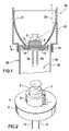
- FIG. 1is a cross-sectional view of the invention, including a reflector.
- FIG. 2is a perspective view, without showing a reflector.
- FIG. 3is a schematic diagram of an exemplary circuit implementing the driving circuit of this invention.
- FIG. 4is similar to FIG. 1 , except that it employs multiple LEDs and a converging lens.
- FIG. 5is a flow diagram of a flashlight related method.
- FIG. 6is another flow diagram of a flashlight related method.
- FIG. 2A perspective view of a preferred physical form for this invention is shown in FIG. 2 .
- FIG. 1A cross-section of FIG. 2 appears as FIG. 1 .
- the standard light bulb power connectoris shown as pins 12 and 14 , respectively conductively connected to the positive and negative power source of the flashlight (presumably batteries).
- the light emitter 3typically would be an LED chip embedded in a transparent plastic lens 2 and a driving circuit embedded in a module. (Of course, potentially more than one light emitting chip could be used, perhaps to simulate white light with multiple chips each emitting a different wavelength.)
- the transparent lens 2 of the light emitterpreferably is so shaped that it refracts a majority of the emitted light laterally toward the reflector 21 .
- Reflector 21would ideally have the shape of a portion of a paraboloid, with the light-emitting chip 3 on the centerline (axis of revolution) near the focal point of the paraboloid.
- reflector 21could simply be a portion of a cone.
- the reflector of the Mini Maglite® and its housingmay be rotated with respect to the flashlight barrel and is attached thereto by the helically threaded, mating portions of the barrel and housing. As the reflector is rotated its focal point is moved along the centerline relative to the light-emitting chip 3 . As the focal point is moved relative to the chip 3 , the shape of the beam reflected off the reflector 21 is changed from a broad cone-like beam to a narrower beam.
- Light ray 23is exemplary of all such rays composing the beam.
- the driver circuit module of the present inventioncomprises a small conventional printed circuit board 4 , circuit components (such as commercially available integrated circuits represented by elements 15 and 17 in FIG. 1 ), a potting layer 6 protecting those circuit components, a socket 9 for the support and conductor leads of the light emitter (LED), and pins 12 and 14 equivalent to the connector of the original incandescent bulb.
- the pins 12 and 14might be instead some other type of connector, such as a standard screw or bayonet light bulb base.
- the dimensions of the module for the Mini Maglite®, for example,would be about 15 mm in diameter and about 3 mm thick—larger than the original incandescent bulb.
- the module 6provides a low friction surface in order for the reflector 21 to readily turn as it contacts module to preserve the focusing capability or to preserve the on-off switch capability.
- the protective material of the module 6must facilitate radiation and conduction of heat away from the light emitters and from the supporting circuit elements in module 6 .
- the materialfor instance, may be a thermally conductive epoxy.
- the moduleis geometrically shaped to maximize surface area within the limited volume to facilitate the radiation of heat from the emitters and the module.
- the surface of the modulemay be textured to increase its surface area.
- the reflectoritself could be fashioned from a thermally conductive material such as stamped aluminum. This would be particularly effective, because it directly contacts the module 6 in the preferred embodiment and because it has a relatively large surface area.
- a replacement reflectoris an optional, additional element of the invention.
- the replacement reflector 21would be essentially identical to the original reflector, except that a small rear portion is removed to account for the thickness of the driver circuit printed circuit board 4 and protective potting 6 .
- the shape of the replacementwould be equivalent to the original, except for the small portion removed from the smaller open end.
- the replacement reflector 21would be modified slightly in shape to account for the new position of the chip relative to the original position of the filament. That is, the relationship of the focal point of the new reflector to the chip would be about the same as the relationship of the focal point of the old reflector to the filament.
- FIG. 4An alternative embodiment is shown in FIG. 4 .
- the LEDsare off the midline axis, so the light will be spread out farther than with the case of FIG. 1 .
- One partial remedywould be to replace the usual flat protective window of the flashlight with a (converging) lens.
- One advantage of multiple LEDsis that they could generate an approximation to white light by mixing the colors of several LEDs (such as that of red, green, and blue LEDs).
- Using a diffusing lens 22 (or reflector 21 )which has a stippled or pebbled surface would smooth the appearance of the light, especially when multiple LEDs are present.
- FIG. 3shows a DC circuit used for a typical embodiment.
- a high frequency, low power DC-to-DC converter circuitis utilized to drive the LED 302 .
- the high frequency of operationallows components of small size to be used.
- a positive voltage sourceis introduced at +Vin 312 and branched to a capacitor Cl 316 and inductor L 1 320 and to two inputs (Vin 324 and EN 326 ) of a switching circuit 304 .
- the solid-state switching circuit 304regulates the input voltage Vin 324 to a specified value to achieve a switched output at SW 328 by receiving an enable signal EN 326 branched from Vin 324 .
- the inductor L 1 320is charged during the ON cycle phase of SW 328 and discharges in the OFF cycle phase to achieve the desired switched voltage output driving a Schottky diode D 1 306 that in turn drives the anode side 308 of the output LED 302 and capacitor C 3 318 which is terminated to ground.
- This Schottky diode D 1 306allows the current to flow in only one direction to the anode side 308 of the LED 302 via SW 328 .
- the Schottky diode D 1 306also assures that there is a quantity of rectification of the AC signal flowing through the circuit so that the LED only sees half of the AC cycle, effectively acting as a DC signal.
- Capacitor C 3 318becomes a charge reservoir, averaging out what would otherwise be a sinusoidally varying voltage with one half of the sine wave missing.
- the cathode side 310 of the LED 302is pass through ground via R- 4 322 and branched to the feedback FB pin 332 of the switching circuit 304 through resistor R 3 320 .
- the FB pin 332acts as half of an operational amplifier that is comparing the voltage at R- 4 322 above ground, to a reference voltage, (i.e., 1.23V).
- a reference voltagei.e. 123V.
- the FB pin 332therefore serves as feedback reference within the switching circuit 304 , determining the current values by comparing a feedback voltage to its internal reference and deciding whether more or less charge is needed, thereby regulating the circuit current.
- ⁇ Vin 314 , capacitors C 1 316 and C 3 318 , resistor R 4 322 and the ground terminal 330 of the switching circuit 304are all terminated to ground.
- a current sense resistoris used to provide the voltage feedback.
- An integrated circuit of small size, Texas Instruments TPS61040 or TPS61041is suitable for this purpose. Although designed for DC-to-DC operation in a suitable voltage range, the circuit can be easily modified to work at higher voltages by using a zener diode resistor combination, or to operate as an AC-to-DC converter by adding a rectifier circuit. Additional operational features such as light sensors, timers, etc., could be added to provide for dimming or automatic shut-off functions. Multiple colored LEDs can be used to vary the desired colored output. Although only one LED is shown, several LEDs can be combined in a series circuit, parallel circuit or series-parallel circuit up to the limitations of the IC used.
- An appropriate LEDmay be chosen for use in this circuit to suit the particular application and sized to closely match the bulb dimensions and intensities of conventional lamps.
- the circuit shown in FIG. 3can be implemented in either a constant voltage output design or a constant current output design.
- the constant current designhas advantages since light output is directly proportional to current, whereas slight variations in the LED manufacture require different operating voltages for a specific light output.
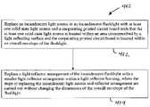
- an incandescent light source in an incandescent flashlightcan be replaced with at least one solid state light source and a cooperating printed circuit board such that the at least one solid state light source is located within an area circumscribed by a light reflecting surface and the cooperating printed circuit board is located within an overall envelope of the flashlight, (step 402 ).
- a light reflector arrangement of the incandescent flashlightcan be replaced with a smaller light reflector arrangement within a light reflector housing, and the steps of replacing the incandescent light source and reflector arrangement are carried out without changing the dimensions of the overall envelope of the flashlight, (step 404 ).
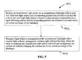
- an incandescent light sourcecan be replaced in an incandescent flashlight with at least one solid state light source and a cooperating printed circuit board such that the at least one solid state light source is located within an area circumscribed by a light reflecting surface and the cooperating printed circuit board is located within an overall envelope of the flashlight, (step 502 ).
- a given battery compartment volume of the flashlightcan be reduced such that the dimensions of an overall envelope of the flashlight remains unchanged, (step 504 ).
Landscapes
- Engineering & Computer Science (AREA)
- General Engineering & Computer Science (AREA)
- Microelectronics & Electronic Packaging (AREA)
- Physics & Mathematics (AREA)
- Optics & Photonics (AREA)
- Circuit Arrangement For Electric Light Sources In General (AREA)
- Arrangement Of Elements, Cooling, Sealing, Or The Like Of Lighting Devices (AREA)
Abstract
Description
| 2 | a transparent lens adapted to emit a majority of the light |
| peripherally | |
| 3 | at least one light-emitting semiconductor chip |
| 4 | a small (round) printed |
| 6 | hard protective material encasing the |
| components | |
| 15 and 17 | |
| 9 | a socket for the LED module comprising 2 and 3 |
| 12 | the pin to be electrically connected to the positive side of |
| the | |
| 14 | the pin to be electrically connected to the negative side of |
| the | |
| 15 | an exemplary integrated circuit (IC) |
| 17 | another integrated circuit (IC) |
| 21 | replacement reflector (shorter than original), if necessary |
| 22 | lens replacing normal protective |
| 23 | exemplary focused |
| 302, . . . , 333 | components of the driving circuit |
Claims (6)
Priority Applications (10)
| Application Number | Priority Date | Filing Date | Title |
|---|---|---|---|
| US11/831,791US7448770B2 (en) | 2004-04-08 | 2007-07-31 | Replacement illumination device for a miniature flashlight bulb |
| US12/244,645US7699494B2 (en) | 2004-04-08 | 2008-10-02 | Replacement illumination device for a miniature flashlight bulb |
| US12/716,633US8033682B2 (en) | 2004-04-08 | 2010-03-03 | Replacement illumination device for an incandescent lamp |
| US13/225,688US8328385B2 (en) | 2003-09-12 | 2011-09-06 | Universal light emitting diode illumination device and method |
| US13/225,691US8328386B2 (en) | 2003-09-12 | 2011-09-06 | Universal light emitting diode illumination device and method |
| US13/225,695US8240873B2 (en) | 2003-09-12 | 2011-09-06 | Universal light emitting diode illumination device and method |
| US13/545,449US8529088B2 (en) | 2003-09-12 | 2012-07-10 | Universal light emitting diode illumination device and method |
| US13/961,454US9103511B2 (en) | 2003-09-12 | 2013-08-07 | Universal light emitting diode illumination device and method |
| US13/961,498US9057489B2 (en) | 2003-09-12 | 2013-08-07 | Universal light emitting diode illumination device and method |
| US14/711,328US20150241044A1 (en) | 2003-09-12 | 2015-05-13 | Universal light emitting diode illumiation device and method |
Applications Claiming Priority (3)
| Application Number | Priority Date | Filing Date | Title |
|---|---|---|---|
| US10/820,930US7318661B2 (en) | 2003-09-12 | 2004-04-08 | Universal light emitting illumination device and method |
| US11/026,796US7300173B2 (en) | 2004-04-08 | 2004-12-31 | Replacement illumination device for a miniature flashlight bulb |
| US11/831,791US7448770B2 (en) | 2004-04-08 | 2007-07-31 | Replacement illumination device for a miniature flashlight bulb |
Related Parent Applications (1)
| Application Number | Title | Priority Date | Filing Date |
|---|---|---|---|
| US11/026,796ContinuationUS7300173B2 (en) | 2003-09-12 | 2004-12-31 | Replacement illumination device for a miniature flashlight bulb |
Related Child Applications (1)
| Application Number | Title | Priority Date | Filing Date |
|---|---|---|---|
| US12/244,645ContinuationUS7699494B2 (en) | 2003-09-12 | 2008-10-02 | Replacement illumination device for a miniature flashlight bulb |
Publications (2)
| Publication Number | Publication Date |
|---|---|
| US20080019123A1 US20080019123A1 (en) | 2008-01-24 |
| US7448770B2true US7448770B2 (en) | 2008-11-11 |
Family
ID=38971262
Family Applications (11)
| Application Number | Title | Priority Date | Filing Date |
|---|---|---|---|
| US11/026,796Expired - Fee RelatedUS7300173B2 (en) | 2003-09-12 | 2004-12-31 | Replacement illumination device for a miniature flashlight bulb |
| US11/831,791Expired - Fee RelatedUS7448770B2 (en) | 2003-09-12 | 2007-07-31 | Replacement illumination device for a miniature flashlight bulb |
| US12/244,645Expired - LifetimeUS7699494B2 (en) | 2003-09-12 | 2008-10-02 | Replacement illumination device for a miniature flashlight bulb |
| US12/716,633Expired - LifetimeUS8033682B2 (en) | 2003-09-12 | 2010-03-03 | Replacement illumination device for an incandescent lamp |
| US13/225,695Expired - Fee RelatedUS8240873B2 (en) | 2003-09-12 | 2011-09-06 | Universal light emitting diode illumination device and method |
| US13/225,691Expired - Fee RelatedUS8328386B2 (en) | 2003-09-12 | 2011-09-06 | Universal light emitting diode illumination device and method |
| US13/225,688Expired - LifetimeUS8328385B2 (en) | 2003-09-12 | 2011-09-06 | Universal light emitting diode illumination device and method |
| US13/545,449Expired - Fee RelatedUS8529088B2 (en) | 2003-09-12 | 2012-07-10 | Universal light emitting diode illumination device and method |
| US13/961,498Expired - LifetimeUS9057489B2 (en) | 2003-09-12 | 2013-08-07 | Universal light emitting diode illumination device and method |
| US13/961,454Expired - LifetimeUS9103511B2 (en) | 2003-09-12 | 2013-08-07 | Universal light emitting diode illumination device and method |
| US14/711,328AbandonedUS20150241044A1 (en) | 2003-09-12 | 2015-05-13 | Universal light emitting diode illumiation device and method |
Family Applications Before (1)
| Application Number | Title | Priority Date | Filing Date |
|---|---|---|---|
| US11/026,796Expired - Fee RelatedUS7300173B2 (en) | 2003-09-12 | 2004-12-31 | Replacement illumination device for a miniature flashlight bulb |
Family Applications After (9)
| Application Number | Title | Priority Date | Filing Date |
|---|---|---|---|
| US12/244,645Expired - LifetimeUS7699494B2 (en) | 2003-09-12 | 2008-10-02 | Replacement illumination device for a miniature flashlight bulb |
| US12/716,633Expired - LifetimeUS8033682B2 (en) | 2003-09-12 | 2010-03-03 | Replacement illumination device for an incandescent lamp |
| US13/225,695Expired - Fee RelatedUS8240873B2 (en) | 2003-09-12 | 2011-09-06 | Universal light emitting diode illumination device and method |
| US13/225,691Expired - Fee RelatedUS8328386B2 (en) | 2003-09-12 | 2011-09-06 | Universal light emitting diode illumination device and method |
| US13/225,688Expired - LifetimeUS8328385B2 (en) | 2003-09-12 | 2011-09-06 | Universal light emitting diode illumination device and method |
| US13/545,449Expired - Fee RelatedUS8529088B2 (en) | 2003-09-12 | 2012-07-10 | Universal light emitting diode illumination device and method |
| US13/961,498Expired - LifetimeUS9057489B2 (en) | 2003-09-12 | 2013-08-07 | Universal light emitting diode illumination device and method |
| US13/961,454Expired - LifetimeUS9103511B2 (en) | 2003-09-12 | 2013-08-07 | Universal light emitting diode illumination device and method |
| US14/711,328AbandonedUS20150241044A1 (en) | 2003-09-12 | 2015-05-13 | Universal light emitting diode illumiation device and method |
Country Status (1)
| Country | Link |
|---|---|
| US (11) | US7300173B2 (en) |
Cited By (9)
| Publication number | Priority date | Publication date | Assignee | Title |
|---|---|---|---|---|
| US20080130288A1 (en)* | 2003-09-12 | 2008-06-05 | Anthony Catalano | Light Emitting Diode Replacement Lamp |
| US20100027085A1 (en)* | 2008-08-01 | 2010-02-04 | Anthony Catalano | Adjustable Beam Portable Light |
| US20110095690A1 (en)* | 2009-10-22 | 2011-04-28 | Thermal Solution Resources, Llc | Overmolded LED Light Assembly and Method of Manufacture |
| US8240873B2 (en) | 2003-09-12 | 2012-08-14 | Terralux, Inc. | Universal light emitting diode illumination device and method |
| US8632215B2 (en) | 2003-11-04 | 2014-01-21 | Terralux, Inc. | Light emitting diode replacement lamp |
| US8702275B2 (en) | 2003-11-04 | 2014-04-22 | Terralux, Inc. | Light-emitting diode replacement lamp |
| US8746930B2 (en) | 2003-11-04 | 2014-06-10 | Terralux, Inc. | Methods of forming direct and decorative illumination |
| US8870408B2 (en) | 2012-04-02 | 2014-10-28 | Streamlight, Inc. | Portable light and work light adapter therefor |
| USD740987S1 (en) | 2012-10-01 | 2015-10-13 | Streamlight, Inc. | Portable light |
Families Citing this family (87)
| Publication number | Priority date | Publication date | Assignee | Title |
|---|---|---|---|---|
| US7758223B2 (en)* | 2005-04-08 | 2010-07-20 | Toshiba Lighting & Technology Corporation | Lamp having outer shell to radiate heat of light source |
| US7633177B2 (en)* | 2005-04-14 | 2009-12-15 | Natural Forces, Llc | Reduced friction wind turbine apparatus and method |
| US20070025109A1 (en)* | 2005-07-26 | 2007-02-01 | Yu Jing J | C7, C9 LED bulb and embedded PCB circuit board |
| US7563070B2 (en)* | 2005-10-27 | 2009-07-21 | Hong Fu Jin Precision Industry (Shen Zhen) Co., Ltd. | Cooling fan |
| ES2718085T3 (en)* | 2005-11-17 | 2019-06-27 | Signify Holding Bv | Lamp set |
| US7488097B2 (en)* | 2006-02-21 | 2009-02-10 | Cml Innovative Technologies, Inc. | LED lamp module |
| DE102006021055A1 (en)* | 2006-05-05 | 2007-11-08 | Patent-Treuhand-Gesellschaft für elektrische Glühlampen mbH | Adapter for a built-in lamp |
| WO2008049381A1 (en)* | 2006-10-25 | 2008-05-02 | Osram Gesellschaft mit beschränkter Haftung | Illumination device |
| WO2008136654A1 (en)* | 2007-05-07 | 2008-11-13 | Thean Kwai Kong | The replacement of all light bulb systems to advanced technology light emitting diode (led) lamps |
| JP4569683B2 (en) | 2007-10-16 | 2010-10-27 | 東芝ライテック株式会社 | Light emitting element lamp and lighting apparatus |
| US10655837B1 (en) | 2007-11-13 | 2020-05-19 | Silescent Lighting Corporation | Light fixture assembly having a heat conductive cover with sufficiently large surface area for improved heat dissipation |
| JP5353216B2 (en)* | 2008-01-07 | 2013-11-27 | 東芝ライテック株式会社 | LED bulb and lighting fixture |
| US8212483B2 (en)* | 2008-06-12 | 2012-07-03 | Infineon Technologies Austria Ag | Brightness controlled light source |
| CN103470983A (en)* | 2008-06-27 | 2013-12-25 | 东芝照明技术株式会社 | Light-emitting element lamp and lighting equipment |
| US8858032B2 (en)* | 2008-10-24 | 2014-10-14 | Cree, Inc. | Lighting device, heat transfer structure and heat transfer element |
| US7922366B2 (en)* | 2008-11-07 | 2011-04-12 | Chia-Mao Li | LED light source with light refractor and reflector |
| JP5333758B2 (en) | 2009-02-27 | 2013-11-06 | 東芝ライテック株式会社 | Lighting device and lighting fixture |
| US8465177B2 (en)* | 2009-06-19 | 2013-06-18 | Chih-Ming Yu | Heat dissipation enhanced LED lamp |
| JP5348410B2 (en) | 2009-06-30 | 2013-11-20 | 東芝ライテック株式会社 | Lamp with lamp and lighting equipment |
| JP2011049527A (en) | 2009-07-29 | 2011-03-10 | Toshiba Lighting & Technology Corp | Led lighting equipment |
| JP2011065979A (en)* | 2009-08-18 | 2011-03-31 | Sharp Corp | Light source device |
| JP2011071242A (en) | 2009-09-24 | 2011-04-07 | Toshiba Lighting & Technology Corp | Light emitting device and illuminating device |
| JP2011091033A (en) | 2009-09-25 | 2011-05-06 | Toshiba Lighting & Technology Corp | Light-emitting module, bulb-shaped lamp and lighting equipment |
| CN102032481B (en) | 2009-09-25 | 2014-01-08 | 东芝照明技术株式会社 | Lighting lamps and lighting fixtures with sockets |
| US8678618B2 (en) | 2009-09-25 | 2014-03-25 | Toshiba Lighting & Technology Corporation | Self-ballasted lamp having a light-transmissive member in contact with light emitting elements and lighting equipment incorporating the same |
| US8324789B2 (en)* | 2009-09-25 | 2012-12-04 | Toshiba Lighting & Technology Corporation | Self-ballasted lamp and lighting equipment |
| JP5174835B2 (en)* | 2010-01-08 | 2013-04-03 | シャープ株式会社 | LED bulb |
| JP5257622B2 (en) | 2010-02-26 | 2013-08-07 | 東芝ライテック株式会社 | Light bulb shaped lamp and lighting equipment |
| DE102010013484A1 (en)* | 2010-03-30 | 2011-10-06 | Hella Kgaa Hueck & Co. | Lighting device for vehicles |
| CN103189684B (en)* | 2010-10-29 | 2016-08-17 | 欧司朗股份有限公司 | Light fixture |
| CN102720983B (en)* | 2011-03-29 | 2015-03-25 | 海洋王照明科技股份有限公司 | Power-optional tunnel lamp |
| CN102734647B (en)* | 2011-04-01 | 2015-07-29 | 亿光电子(中国)有限公司 | White lumination system |
| JP6010116B2 (en)* | 2011-06-06 | 2016-10-19 | フィリップス ライティング ホールディング ビー ヴィ | Socket, lighting module, and lighting fixture |
| CN102261591A (en)* | 2011-08-10 | 2011-11-30 | 戴培钧 | Light emitting diode (LED) lamp capable of emitting light reversely |
| US8692473B2 (en)* | 2011-08-23 | 2014-04-08 | Mag Instrument, Inc. | Portable lighting device |
| CN102364210A (en)* | 2011-10-25 | 2012-02-29 | 江门海琪电子科技有限公司 | LED (Light-Emitting Diode) lamp with hidden heat radiator |
| CN102364214A (en)* | 2011-11-01 | 2012-02-29 | 西安金诺光电科技有限公司 | Light-emitting diode (LED) bulb |
| TWM426729U (en)* | 2011-11-15 | 2012-04-11 | Unity Opto Technology Co Ltd | Improved LED bulb structure |
| US8777443B2 (en)* | 2011-12-13 | 2014-07-15 | Kuo-Fu Yang | Split type LED lamp |
| JP2014011045A (en)* | 2012-06-29 | 2014-01-20 | Toshiba Lighting & Technology Corp | Lighting device and lighting system |
| CN102809128B (en)* | 2012-07-27 | 2014-03-05 | 重庆雷士实业有限公司 | Semiconductor lighting device |
| CN102818190A (en)* | 2012-08-08 | 2012-12-12 | 上海微分节能科技有限公司 | Crystal flower type light source, lamp bulb and pendant lamp |
| US9204504B2 (en) | 2012-09-17 | 2015-12-01 | Energy Focus, Inc. | LED lamp system |
| US20140092590A1 (en)* | 2012-10-01 | 2014-04-03 | Rambus Delaware Llc | Led flashlight |
| US20140153241A1 (en)* | 2012-12-01 | 2014-06-05 | Lsi Industries, Inc. | Display board and display board components |
| US9062863B2 (en)* | 2012-12-10 | 2015-06-23 | Avago Technologies General Ip (Singapore) Pte. Ltd. | System, device, and method for adjusting color output through active cooling mechanism |
| US9313849B2 (en) | 2013-01-23 | 2016-04-12 | Silescent Lighting Corporation | Dimming control system for solid state illumination source |
| DE102013201219A1 (en)* | 2013-01-25 | 2014-07-31 | Osram Opto Semiconductors Gmbh | Lamp |
| TWM462333U (en)* | 2013-02-05 | 2013-09-21 | Hep Tech Co Ltd | Switchable dimming apparatus for LED |
| US8884530B2 (en)* | 2013-02-07 | 2014-11-11 | Wen-Sung Lee | Intelligent illuminating device |
| EP2775598B1 (en)* | 2013-03-05 | 2018-01-17 | Dialog Semiconductor GmbH | Active avalanche protection for flyback converter |
| USD715481S1 (en)* | 2013-03-11 | 2014-10-14 | Wan-Jiong Lin | Lens |
| USD715991S1 (en)* | 2013-03-11 | 2014-10-21 | Wan-Jiong Lin | Lens |
| USD715990S1 (en)* | 2013-03-11 | 2014-10-21 | Wan-Jiong Lin | Lens |
| US10265539B2 (en) | 2013-04-30 | 2019-04-23 | Lpi, Inc. | Therapeutic LED system for a hot tub |
| CN104344355A (en)* | 2013-08-08 | 2015-02-11 | 欧司朗股份有限公司 | Light-emitting device with zoom function |
| US9976710B2 (en) | 2013-10-30 | 2018-05-22 | Lilibrand Llc | Flexible strip lighting apparatus and methods |
| JP6467206B2 (en)* | 2014-01-28 | 2019-02-06 | 株式会社小糸製作所 | Light source unit |
| US20150272262A1 (en)* | 2014-03-31 | 2015-10-01 | Sam Escamilla | Illuminated Shoe Insert |
| US9562677B2 (en)* | 2014-04-09 | 2017-02-07 | Cree, Inc. | LED lamp having at least two sectors |
| US9410688B1 (en) | 2014-05-09 | 2016-08-09 | Mark Sutherland | Heat dissipating assembly |
| US9488352B2 (en)* | 2014-05-28 | 2016-11-08 | Technical Consumer Products, Inc. | Radio frequency (RF) signal pathway for a lamp antenna |
| US9380653B1 (en) | 2014-10-31 | 2016-06-28 | Dale Stepps | Driver assembly for solid state lighting |
| EP3238278B1 (en)* | 2014-12-22 | 2020-03-04 | MAG Instrument, Inc. | Improved efficiency lighting apparatus with led directly mounted to a heatsink |
| FR3032516B1 (en)* | 2015-02-06 | 2021-04-16 | Valeo Vision | LUMINOUS MODULE REFLECTOR DEVICE WITH ELECTROMAGNETIC SHIELDING |
| DE202015102507U1 (en)* | 2015-05-15 | 2015-06-10 | Bernd Beisse | LED light |
| USD811627S1 (en) | 2016-06-16 | 2018-02-27 | Curtis Alan Roys | LED lamp |
| JP6508468B2 (en)* | 2015-07-24 | 2019-05-08 | 東芝ライテック株式会社 | Vehicle lighting device and vehicle lighting device |
| US11060702B2 (en) | 2016-03-08 | 2021-07-13 | Ecosense Lighting Inc. | Lighting system with lens assembly |
| MY170228A (en)* | 2016-03-31 | 2019-07-10 | Fuji Oil Holdings Inc | Fat composition for low-trans fat, non-tempered chocolate and chocolate |
| US10041657B2 (en)* | 2016-06-13 | 2018-08-07 | Rebo Lighting & Electronics, Llc | Clip unit and edge mounted light emitting diode (LED) assembly comprising a clip unit |
| WO2018140727A1 (en) | 2017-01-27 | 2018-08-02 | Lilibrand Llc | Lighting systems with high color rendering index and uniform planar illumination |
| US12388056B1 (en) | 2017-01-27 | 2025-08-12 | Korrus, Inc. | Linear lighting systems and processes |
| US10435175B2 (en) | 2017-01-31 | 2019-10-08 | Honeywell International Inc. | Light emitting diode lamp assembly |
| US20180328552A1 (en) | 2017-03-09 | 2018-11-15 | Lilibrand Llc | Fixtures and lighting accessories for lighting devices |
| USD901754S1 (en) | 2017-04-14 | 2020-11-10 | RetroLED Components, LLC | Lamp support |
| USD851816S1 (en) | 2017-04-14 | 2019-06-18 | Curtis A. Roys | Lamp support |
| US10690312B2 (en) | 2017-05-18 | 2020-06-23 | Tri Lite, Inc. | Light emitting diode signal light |
| US10856679B2 (en)* | 2017-07-28 | 2020-12-08 | Just Funky Llc | Illumination element receptacle |
| US11041609B2 (en) | 2018-05-01 | 2021-06-22 | Ecosense Lighting Inc. | Lighting systems and devices with central silicone module |
| US10443834B1 (en)* | 2018-06-06 | 2019-10-15 | Mag Instrument, Inc. | LED flashlight with improved heat sink |
| US10683988B2 (en)* | 2018-10-04 | 2020-06-16 | Elemental LED, Inc. | Mirrored LED lighting |
| US10605412B1 (en) | 2018-11-16 | 2020-03-31 | Emeryallen, Llc | Miniature integrated omnidirectional LED bulb |
| US11353200B2 (en) | 2018-12-17 | 2022-06-07 | Korrus, Inc. | Strip lighting system for direct input of high voltage driving power |
| CN109695842B (en)* | 2019-01-07 | 2024-06-11 | 佛山电器照明股份有限公司 | LED lamp |
| US11002438B2 (en) | 2019-04-03 | 2021-05-11 | Sidney Howard Norton | Adjustable clip-on base for LED assembly |
| CN113503475B (en)* | 2021-06-25 | 2023-02-24 | 浙江浩腾电子科技股份有限公司 | A multifunctional solar voice lighting system |
Citations (47)
| Publication number | Priority date | Publication date | Assignee | Title |
|---|---|---|---|---|
| US3795830A (en) | 1972-08-17 | 1974-03-05 | Shelton J | Led slidebase switchboard lamp |
| US4211955A (en) | 1978-03-02 | 1980-07-08 | Ray Stephen W | Solid state lamp |
| US4727289A (en) | 1985-07-22 | 1988-02-23 | Stanley Electric Co., Ltd. | LED lamp |
| US5097180A (en) | 1990-09-14 | 1992-03-17 | Roger Ignon | Flickering candle lamp |
| US5189339A (en) | 1990-09-05 | 1993-02-23 | Applied Lumens, Ltd. | Fluorescent lamp assemblies |
| US5222800A (en) | 1992-01-28 | 1993-06-29 | The Genlyte Group Incorporated | Recessed lighting fixture |
| US5463280A (en) | 1994-03-03 | 1995-10-31 | National Service Industries, Inc. | Light emitting diode retrofit lamp |
| US5465197A (en) | 1994-06-07 | 1995-11-07 | Chien; Tseng-Lu | Portable light |
| US5561346A (en) | 1994-08-10 | 1996-10-01 | Byrne; David J. | LED lamp construction |
| US5575459A (en) | 1995-04-27 | 1996-11-19 | Uniglo Canada Inc. | Light emitting diode lamp |
| US5632551A (en) | 1994-07-18 | 1997-05-27 | Grote Industries, Inc. | LED vehicle lamp assembly |
| US5655830A (en) | 1993-12-01 | 1997-08-12 | General Signal Corporation | Lighting device |
| US5663719A (en) | 1993-04-29 | 1997-09-02 | Electro-Tech's | LED traffic signal light with automatic low-line voltage compensating circuit |
| US5850126A (en) | 1997-04-11 | 1998-12-15 | Kanbar; Maurice S. | Screw-in led lamp |
| US5936599A (en) | 1995-01-27 | 1999-08-10 | Reymond; Welles | AC powered light emitting diode array circuits for use in traffic signal displays |
| US5994845A (en) | 1997-04-24 | 1999-11-30 | Ventur Research & Development Inc. | Electrical light socket |
| US6019493A (en) | 1998-03-13 | 2000-02-01 | Kuo; Jeffrey | High efficiency light for use in a traffic signal light, using LED's |
| US6091614A (en) | 1997-12-17 | 2000-07-18 | Ecolux Inc. | Voltage booster for enabling the power factor controller of a LED lamp upon low ac or dc supply |
| US6140776A (en) | 1999-04-06 | 2000-10-31 | Rachwal; Erwin J. | Flashlight |
| US6150771A (en) | 1997-06-11 | 2000-11-21 | Precision Solar Controls Inc. | Circuit for interfacing between a conventional traffic signal conflict monitor and light emitting diodes replacing a conventional incandescent bulb in the signal |
| US6190020B1 (en)* | 1999-06-23 | 2001-02-20 | Fred Jack Hartley | Light producing assembly for a flashlight |
| US6218785B1 (en) | 1999-03-19 | 2001-04-17 | Incerti & Simonini Di Incerti Edda & C. S.N.C. | Low-tension lighting device |
| US6232784B1 (en) | 1997-09-22 | 2001-05-15 | Richard Dulasky | Circuit continuity tester and method |
| US6234648B1 (en) | 1998-09-28 | 2001-05-22 | U.S. Philips Corporation | Lighting system |
| US6310445B1 (en) | 2000-01-03 | 2001-10-30 | Dialight Corporation | Led indicator disable circuit and led indicator incorporating the led indicator disable circuit |
| US6371636B1 (en) | 1999-05-24 | 2002-04-16 | Jam Strait, Inc. | LED light module for vehicles |
| US6380865B1 (en) | 1999-04-06 | 2002-04-30 | 911 Emergency Products, Inc. | Replacement led lamp assembly and modulated power intensity for light source |
| US20020141196A1 (en) | 2001-03-30 | 2002-10-03 | Richard Camarota | Lamp assembly with selectively positionable bulb |
| US6485160B1 (en) | 2001-06-25 | 2002-11-26 | Gelcore Llc | Led flashlight with lens |
| US6528954B1 (en) | 1997-08-26 | 2003-03-04 | Color Kinetics Incorporated | Smart light bulb |
| US20030067787A1 (en) | 2001-10-04 | 2003-04-10 | Koito Manufacturing Co., Ltd. | Vehicle lamp |
| US6570505B1 (en) | 1997-12-30 | 2003-05-27 | Gelcore Llc | LED lamp with a fault-indicating impedance-changing circuit |
| US20030112627A1 (en) | 2000-09-28 | 2003-06-19 | Deese Raymond E. | Flexible sign illumination apparatus, system and method |
| US6644841B2 (en) | 2002-03-01 | 2003-11-11 | Gelcore Llc | Light emitting diode reflector |
| US20030210552A1 (en) | 2002-03-13 | 2003-11-13 | Reinhold Barlian | Indicating light |
| US20040070990A1 (en) | 2002-10-01 | 2004-04-15 | Witold Szypszak | LED illuminator and method of manufacture |
| US6727652B2 (en) | 2000-12-21 | 2004-04-27 | Gamesman Limited | Lamps |
| JP2004146205A (en) | 2002-10-24 | 2004-05-20 | Fuji Photo Film Co Ltd | Battery storing device |
| US6791283B2 (en) | 2001-09-07 | 2004-09-14 | Opalec | Dual mode regulated light-emitting diode module for flashlights |
| US20040189262A1 (en) | 2003-03-10 | 2004-09-30 | Leddynamics | Circuit devices, circuit devices which include light emitting diodes, assemblies which include such circuit devices, flashlights which include such assemblies, and methods for directly replacing flashlight bulbs |
| US6819056B2 (en) | 2003-04-15 | 2004-11-16 | Yeoujyi Electronics Co., Ltd. | Color-changing bulb of instrument panel of a vehicle |
| US20050052865A1 (en) | 2003-09-05 | 2005-03-10 | Guide Corporation | Lamp housing containing an integrated LED support structure |
| US6893140B2 (en) | 2002-12-13 | 2005-05-17 | W. T. Storey, Inc. | Flashlight |
| US6924606B2 (en) | 2003-09-16 | 2005-08-02 | Beyond Innovation Technology Co., Ltd. | Low-visual noise, jitterized pulse width modulation brightness control circuit |
| US6957897B1 (en)* | 2000-06-27 | 2005-10-25 | General Electric Company | Flashlight with light emitting diode source |
| US6981784B2 (en) | 2002-05-30 | 2006-01-03 | Gelcore, Llc | Side projecting LED signal |
| US7008084B2 (en) | 2003-01-03 | 2006-03-07 | Galli Robert D | Lighting head assembly with integrated heat sink |
Family Cites Families (65)
| Publication number | Priority date | Publication date | Assignee | Title |
|---|---|---|---|---|
| US4214295A (en) | 1975-12-22 | 1980-07-22 | Oldham Batteries Limited | Portable electric lamp adjustable from spot beam to diffused beam |
| US4783726A (en) | 1987-06-12 | 1988-11-08 | Wang Chern J | Modular light device |
| US4999750A (en)* | 1989-07-20 | 1991-03-12 | Gammache Richard J | Flashlight with rotatable head assembly |
| US6733152B2 (en)* | 1991-06-21 | 2004-05-11 | Mag Instrument, Inc. | Flashlight |
| US5749646A (en)* | 1992-01-17 | 1998-05-12 | Brittell; Gerald A. | Special effect lamps |
| US5473525A (en) | 1993-02-24 | 1995-12-05 | Stout; Gary F. | Discreet display lamp |
| DE4321823C2 (en) | 1993-07-01 | 1997-03-06 | Telefunken Microelectron | Illumination unit for illuminated signs |
| US5555161A (en) | 1995-09-11 | 1996-09-10 | Delco Electronics Corporation | Bi-functional light pipe and display assembly |
| US5806973A (en) | 1996-06-28 | 1998-09-15 | The L.D. Kichler Co. | Lamp with illuminated body |
| JP3449898B2 (en) | 1997-10-16 | 2003-09-22 | 富士通株式会社 | Light emitting element drive circuit |
| WO2000017569A1 (en)* | 1998-09-17 | 2000-03-30 | Koninklijke Philips Electronics N.V. | Led lamp |
| US6793374B2 (en)* | 1998-09-17 | 2004-09-21 | Simon H. A. Begemann | LED lamp |
| TW417842U (en) | 1998-09-28 | 2001-01-01 | Koninkl Philips Electronics Nv | Lighting system |
| JP2000258495A (en) | 1999-03-12 | 2000-09-22 | Oki Electric Ind Co Ltd | Semiconductor device testing device |
| JP2001028427A (en)* | 1999-07-14 | 2001-01-30 | Mitsubishi Electric Corp | Nonvolatile semiconductor memory device |
| US6111739A (en) | 1999-08-11 | 2000-08-29 | Leotek Electronics Corporation | LED power supply with temperature compensation |
| US6504301B1 (en) | 1999-09-03 | 2003-01-07 | Lumileds Lighting, U.S., Llc | Non-incandescent lightbulb package using light emitting diodes |
| JP3445540B2 (en) | 1999-11-16 | 2003-09-08 | 常盤電業株式会社 | Power circuit |
| US6184628B1 (en)* | 1999-11-30 | 2001-02-06 | Douglas Ruthenberg | Multicolor led lamp bulb for underwater pool lights |
| US6357889B1 (en) | 1999-12-01 | 2002-03-19 | General Electric Company | Color tunable light source |
| US6161910A (en) | 1999-12-14 | 2000-12-19 | Aerospace Lighting Corporation | LED reading light |
| US6285139B1 (en) | 1999-12-23 | 2001-09-04 | Gelcore, Llc | Non-linear light-emitting load current control |
| US6626557B1 (en) | 1999-12-29 | 2003-09-30 | Spx Corporation | Multi-colored industrial signal device |
| US6595671B2 (en) | 2000-05-10 | 2003-07-22 | Maxime Lefebvre | Rugged, waterproof LED array lighting system |
| US6580228B1 (en)* | 2000-08-22 | 2003-06-17 | Light Sciences Corporation | Flexible substrate mounted solid-state light sources for use in line current lamp sockets |
| US7262752B2 (en) | 2001-01-16 | 2007-08-28 | Visteon Global Technologies, Inc. | Series led backlight control circuit |
| US6857756B2 (en) | 2001-04-11 | 2005-02-22 | General Manufacturing, Inc. | LED work light |
| WO2002097884A1 (en) | 2001-05-26 | 2002-12-05 | Gelcore, Llc | High power led module for spot illumination |
| US6634770B2 (en)* | 2001-08-24 | 2003-10-21 | Densen Cao | Light source using semiconductor devices mounted on a heat sink |
| US6634771B2 (en)* | 2001-08-24 | 2003-10-21 | Densen Cao | Semiconductor light source using a primary and secondary heat sink combination |
| US7331681B2 (en) | 2001-09-07 | 2008-02-19 | Litepanels Llc | Lighting apparatus with adjustable lenses or filters |
| US7204602B2 (en)* | 2001-09-07 | 2007-04-17 | Super Vision International, Inc. | Light emitting diode pool assembly |
| US6871983B2 (en)* | 2001-10-25 | 2005-03-29 | Tir Systems Ltd. | Solid state continuous sealed clean room light fixture |
| US20030103348A1 (en) | 2001-11-30 | 2003-06-05 | Sheng-Tien Hung | Projection lamp |
| EP1461979B1 (en) | 2002-01-07 | 2008-12-31 | Patent-Treuhand-Gesellschaft für elektrische Glühlampen mbH | Lamp |
| US7273987B2 (en) | 2002-03-21 | 2007-09-25 | General Electric Company | Flexible interconnect structures for electrical devices and light sources incorporating the same |
| US6880951B2 (en)* | 2002-04-04 | 2005-04-19 | Altec Co., Ltd. | Flashlight using a light emitting diode as a lamp |
| JP4108400B2 (en) | 2002-07-24 | 2008-06-25 | 富士通株式会社 | Driving circuit and driving method of semiconductor laser module having electroabsorption optical modulator |
| JP2004119287A (en) | 2002-09-27 | 2004-04-15 | Toto Ltd | Lighting equipment for toilet |
| US6853151B2 (en) | 2002-11-19 | 2005-02-08 | Denovo Lighting, Llc | LED retrofit lamp |
| US6924605B2 (en) | 2002-11-27 | 2005-08-02 | James K. Chun | Combination voltage detector and LED flashlight |
| US20040190286A1 (en)* | 2003-03-25 | 2004-09-30 | Chapman Leonard T. | Flashlight |
| US7604378B2 (en) | 2003-07-02 | 2009-10-20 | S.C. Johnson & Son, Inc. | Color changing outdoor lights with active ingredient and sound emission |
| US6882111B2 (en)* | 2003-07-09 | 2005-04-19 | Tir Systems Ltd. | Strip lighting system incorporating light emitting devices |
| US7300173B2 (en) | 2004-04-08 | 2007-11-27 | Technology Assessment Group, Inc. | Replacement illumination device for a miniature flashlight bulb |
| US7318661B2 (en) | 2003-09-12 | 2008-01-15 | Anthony Catalano | Universal light emitting illumination device and method |
| US7777430B2 (en) | 2003-09-12 | 2010-08-17 | Terralux, Inc. | Light emitting diode replacement lamp |
| US7296913B2 (en) | 2004-07-16 | 2007-11-20 | Technology Assessment Group | Light emitting diode replacement lamp |
| US8702275B2 (en) | 2003-11-04 | 2014-04-22 | Terralux, Inc. | Light-emitting diode replacement lamp |
| US8632215B2 (en) | 2003-11-04 | 2014-01-21 | Terralux, Inc. | Light emitting diode replacement lamp |
| US8746930B2 (en) | 2003-11-04 | 2014-06-10 | Terralux, Inc. | Methods of forming direct and decorative illumination |
| US7118249B2 (en) | 2004-01-16 | 2006-10-10 | Fu-Hsien Hsu | Decorative illuminated article adapted for use with a lighting string |
| US6948829B2 (en)* | 2004-01-28 | 2005-09-27 | Dialight Corporation | Light emitting diode (LED) light bulbs |
| US20070019415A1 (en) | 2005-04-22 | 2007-01-25 | Itt Industries | LED floodlight system |
| US20060250270A1 (en) | 2005-05-05 | 2006-11-09 | Kyrre Tangen | System and method for mounting a light emitting diode to a printed circuit board |
| JP4577846B2 (en) | 2006-02-28 | 2010-11-10 | スタンレー電気株式会社 | Lighting device |
| US7806574B2 (en) | 2006-04-16 | 2010-10-05 | Albeo Technologies, Inc. | Thermal management of LED-based lighting systems |
| US20080080184A1 (en) | 2006-10-03 | 2008-04-03 | Cao Group Inc. | Pixilated LED Light Source for Channel Letter Illumination |
| US7852015B1 (en) | 2006-10-11 | 2010-12-14 | SemiLEDs Optoelectronics Co., Ltd. | Solid state lighting system and maintenance method therein |
| US7808013B2 (en) | 2006-10-31 | 2010-10-05 | Cree, Inc. | Integrated heat spreaders for light emitting devices (LEDs) and related assemblies |
| US8297796B2 (en) | 2008-08-01 | 2012-10-30 | Terralux, Inc. | Adjustable beam portable light |
| JP5379166B2 (en) | 2009-01-20 | 2013-12-25 | パナソニック株式会社 | Lighting device |
| JP5298389B2 (en) | 2009-07-06 | 2013-09-25 | 株式会社エルム | LED bulb |
| CN102109103B (en) | 2009-12-28 | 2013-02-27 | 旭丽电子(广州)有限公司 | Lamp and lamp holder module thereof |
| JP2012099297A (en) | 2010-11-01 | 2012-05-24 | Keiji Iimura | Led lamp and led bulb |
- 2004
- 2004-12-31USUS11/026,796patent/US7300173B2/ennot_activeExpired - Fee Related
- 2007
- 2007-07-31USUS11/831,791patent/US7448770B2/ennot_activeExpired - Fee Related
- 2008
- 2008-10-02USUS12/244,645patent/US7699494B2/ennot_activeExpired - Lifetime
- 2010
- 2010-03-03USUS12/716,633patent/US8033682B2/ennot_activeExpired - Lifetime
- 2011
- 2011-09-06USUS13/225,695patent/US8240873B2/ennot_activeExpired - Fee Related
- 2011-09-06USUS13/225,691patent/US8328386B2/ennot_activeExpired - Fee Related
- 2011-09-06USUS13/225,688patent/US8328385B2/ennot_activeExpired - Lifetime
- 2012
- 2012-07-10USUS13/545,449patent/US8529088B2/ennot_activeExpired - Fee Related
- 2013
- 2013-08-07USUS13/961,498patent/US9057489B2/ennot_activeExpired - Lifetime
- 2013-08-07USUS13/961,454patent/US9103511B2/ennot_activeExpired - Lifetime
- 2015
- 2015-05-13USUS14/711,328patent/US20150241044A1/ennot_activeAbandoned
Patent Citations (48)
| Publication number | Priority date | Publication date | Assignee | Title |
|---|---|---|---|---|
| US3795830A (en) | 1972-08-17 | 1974-03-05 | Shelton J | Led slidebase switchboard lamp |
| US4211955A (en) | 1978-03-02 | 1980-07-08 | Ray Stephen W | Solid state lamp |
| US4727289A (en) | 1985-07-22 | 1988-02-23 | Stanley Electric Co., Ltd. | LED lamp |
| US5189339A (en) | 1990-09-05 | 1993-02-23 | Applied Lumens, Ltd. | Fluorescent lamp assemblies |
| US5097180A (en) | 1990-09-14 | 1992-03-17 | Roger Ignon | Flickering candle lamp |
| US5222800A (en) | 1992-01-28 | 1993-06-29 | The Genlyte Group Incorporated | Recessed lighting fixture |
| US5663719A (en) | 1993-04-29 | 1997-09-02 | Electro-Tech's | LED traffic signal light with automatic low-line voltage compensating circuit |
| US5655830A (en) | 1993-12-01 | 1997-08-12 | General Signal Corporation | Lighting device |
| US5463280A (en) | 1994-03-03 | 1995-10-31 | National Service Industries, Inc. | Light emitting diode retrofit lamp |
| US5465197A (en) | 1994-06-07 | 1995-11-07 | Chien; Tseng-Lu | Portable light |
| US5632551A (en) | 1994-07-18 | 1997-05-27 | Grote Industries, Inc. | LED vehicle lamp assembly |
| US5561346A (en) | 1994-08-10 | 1996-10-01 | Byrne; David J. | LED lamp construction |
| US5936599A (en) | 1995-01-27 | 1999-08-10 | Reymond; Welles | AC powered light emitting diode array circuits for use in traffic signal displays |
| US5575459A (en) | 1995-04-27 | 1996-11-19 | Uniglo Canada Inc. | Light emitting diode lamp |
| US5850126A (en) | 1997-04-11 | 1998-12-15 | Kanbar; Maurice S. | Screw-in led lamp |
| US5994845A (en) | 1997-04-24 | 1999-11-30 | Ventur Research & Development Inc. | Electrical light socket |
| US6150771A (en) | 1997-06-11 | 2000-11-21 | Precision Solar Controls Inc. | Circuit for interfacing between a conventional traffic signal conflict monitor and light emitting diodes replacing a conventional incandescent bulb in the signal |
| US6528954B1 (en) | 1997-08-26 | 2003-03-04 | Color Kinetics Incorporated | Smart light bulb |
| US6232784B1 (en) | 1997-09-22 | 2001-05-15 | Richard Dulasky | Circuit continuity tester and method |
| US6091614A (en) | 1997-12-17 | 2000-07-18 | Ecolux Inc. | Voltage booster for enabling the power factor controller of a LED lamp upon low ac or dc supply |
| US6570505B1 (en) | 1997-12-30 | 2003-05-27 | Gelcore Llc | LED lamp with a fault-indicating impedance-changing circuit |
| US6019493A (en) | 1998-03-13 | 2000-02-01 | Kuo; Jeffrey | High efficiency light for use in a traffic signal light, using LED's |
| US6234648B1 (en) | 1998-09-28 | 2001-05-22 | U.S. Philips Corporation | Lighting system |
| US6218785B1 (en) | 1999-03-19 | 2001-04-17 | Incerti & Simonini Di Incerti Edda & C. S.N.C. | Low-tension lighting device |
| US6140776A (en) | 1999-04-06 | 2000-10-31 | Rachwal; Erwin J. | Flashlight |
| US6380865B1 (en) | 1999-04-06 | 2002-04-30 | 911 Emergency Products, Inc. | Replacement led lamp assembly and modulated power intensity for light source |
| US6371636B1 (en) | 1999-05-24 | 2002-04-16 | Jam Strait, Inc. | LED light module for vehicles |
| US6190020B1 (en)* | 1999-06-23 | 2001-02-20 | Fred Jack Hartley | Light producing assembly for a flashlight |
| US6310445B1 (en) | 2000-01-03 | 2001-10-30 | Dialight Corporation | Led indicator disable circuit and led indicator incorporating the led indicator disable circuit |
| US6957897B1 (en)* | 2000-06-27 | 2005-10-25 | General Electric Company | Flashlight with light emitting diode source |
| US20030112627A1 (en) | 2000-09-28 | 2003-06-19 | Deese Raymond E. | Flexible sign illumination apparatus, system and method |
| US6727652B2 (en) | 2000-12-21 | 2004-04-27 | Gamesman Limited | Lamps |
| US20020141196A1 (en) | 2001-03-30 | 2002-10-03 | Richard Camarota | Lamp assembly with selectively positionable bulb |
| US6485160B1 (en) | 2001-06-25 | 2002-11-26 | Gelcore Llc | Led flashlight with lens |
| US6791283B2 (en) | 2001-09-07 | 2004-09-14 | Opalec | Dual mode regulated light-emitting diode module for flashlights |
| US20030067787A1 (en) | 2001-10-04 | 2003-04-10 | Koito Manufacturing Co., Ltd. | Vehicle lamp |
| US6644841B2 (en) | 2002-03-01 | 2003-11-11 | Gelcore Llc | Light emitting diode reflector |
| US20030210552A1 (en) | 2002-03-13 | 2003-11-13 | Reinhold Barlian | Indicating light |
| US6981784B2 (en) | 2002-05-30 | 2006-01-03 | Gelcore, Llc | Side projecting LED signal |
| US20040070990A1 (en) | 2002-10-01 | 2004-04-15 | Witold Szypszak | LED illuminator and method of manufacture |
| JP2004146205A (en) | 2002-10-24 | 2004-05-20 | Fuji Photo Film Co Ltd | Battery storing device |
| US6893140B2 (en) | 2002-12-13 | 2005-05-17 | W. T. Storey, Inc. | Flashlight |
| US7008084B2 (en) | 2003-01-03 | 2006-03-07 | Galli Robert D | Lighting head assembly with integrated heat sink |
| US20040189262A1 (en) | 2003-03-10 | 2004-09-30 | Leddynamics | Circuit devices, circuit devices which include light emitting diodes, assemblies which include such circuit devices, flashlights which include such assemblies, and methods for directly replacing flashlight bulbs |
| US7015650B2 (en)* | 2003-03-10 | 2006-03-21 | Leddynamics | Circuit devices, circuit devices which include light emitting diodes, assemblies which include such circuit devices, flashlights which include such assemblies, and methods for directly replacing flashlight bulbs |
| US6819056B2 (en) | 2003-04-15 | 2004-11-16 | Yeoujyi Electronics Co., Ltd. | Color-changing bulb of instrument panel of a vehicle |
| US20050052865A1 (en) | 2003-09-05 | 2005-03-10 | Guide Corporation | Lamp housing containing an integrated LED support structure |
| US6924606B2 (en) | 2003-09-16 | 2005-08-02 | Beyond Innovation Technology Co., Ltd. | Low-visual noise, jitterized pulse width modulation brightness control circuit |
Cited By (23)
| Publication number | Priority date | Publication date | Assignee | Title |
|---|---|---|---|---|
| US8529088B2 (en) | 2003-09-12 | 2013-09-10 | Terralux, Inc. | Universal light emitting diode illumination device and method |
| US8400081B2 (en) | 2003-09-12 | 2013-03-19 | Terralux, Inc. | Light emitting diode replacement lamp |
| US7777430B2 (en) | 2003-09-12 | 2010-08-17 | Terralux, Inc. | Light emitting diode replacement lamp |
| US20100320499A1 (en)* | 2003-09-12 | 2010-12-23 | Terralux, Inc. | Light emitting diode replacement lamp |
| US9622316B2 (en) | 2003-09-12 | 2017-04-11 | Terralux, Inc. | Light emitting diode replacement lamp |
| US8240873B2 (en) | 2003-09-12 | 2012-08-14 | Terralux, Inc. | Universal light emitting diode illumination device and method |
| US20080130288A1 (en)* | 2003-09-12 | 2008-06-05 | Anthony Catalano | Light Emitting Diode Replacement Lamp |
| US9057489B2 (en) | 2003-09-12 | 2015-06-16 | Terralux, Inc. | Universal light emitting diode illumination device and method |
| US9103511B2 (en) | 2003-09-12 | 2015-08-11 | Terralux, Inc. | Universal light emitting diode illumination device and method |
| US9049768B2 (en) | 2003-09-12 | 2015-06-02 | Terralux, Inc. | Light emitting diode replacement lamp |
| US8823290B2 (en) | 2003-09-12 | 2014-09-02 | Terralux, Inc. | Light emitting diode replacement lamp |
| US8328385B2 (en) | 2003-09-12 | 2012-12-11 | Terralux, Inc. | Universal light emitting diode illumination device and method |
| US8328386B2 (en) | 2003-09-12 | 2012-12-11 | Terralux, Inc. | Universal light emitting diode illumination device and method |
| US8746930B2 (en) | 2003-11-04 | 2014-06-10 | Terralux, Inc. | Methods of forming direct and decorative illumination |
| US9429280B2 (en) | 2003-11-04 | 2016-08-30 | Terralux, Inc. | Light emitting diode replacement lamp |
| US8632215B2 (en) | 2003-11-04 | 2014-01-21 | Terralux, Inc. | Light emitting diode replacement lamp |
| US8702275B2 (en) | 2003-11-04 | 2014-04-22 | Terralux, Inc. | Light-emitting diode replacement lamp |
| US8297796B2 (en) | 2008-08-01 | 2012-10-30 | Terralux, Inc. | Adjustable beam portable light |
| US20100027085A1 (en)* | 2008-08-01 | 2010-02-04 | Anthony Catalano | Adjustable Beam Portable Light |
| US8827508B2 (en) | 2009-10-22 | 2014-09-09 | Thermal Solution Resources, Llc | Overmolded LED light assembly and method of manufacture |
| US20110095690A1 (en)* | 2009-10-22 | 2011-04-28 | Thermal Solution Resources, Llc | Overmolded LED Light Assembly and Method of Manufacture |
| US8870408B2 (en) | 2012-04-02 | 2014-10-28 | Streamlight, Inc. | Portable light and work light adapter therefor |
| USD740987S1 (en) | 2012-10-01 | 2015-10-13 | Streamlight, Inc. | Portable light |
Also Published As
| Publication number | Publication date |
|---|---|
| US7300173B2 (en) | 2007-11-27 |
| US8033682B2 (en) | 2011-10-11 |
| US8328385B2 (en) | 2012-12-11 |
| US8240873B2 (en) | 2012-08-14 |
| US9103511B2 (en) | 2015-08-11 |
| US8328386B2 (en) | 2012-12-11 |
| US20120320575A1 (en) | 2012-12-20 |
| US20150241044A1 (en) | 2015-08-27 |
| US9057489B2 (en) | 2015-06-16 |
| US20120044673A1 (en) | 2012-02-23 |
| US20100165611A1 (en) | 2010-07-01 |
| US20140036488A1 (en) | 2014-02-06 |
| US8529088B2 (en) | 2013-09-10 |
| US20120044674A1 (en) | 2012-02-23 |
| US20090034262A1 (en) | 2009-02-05 |
| US20080019123A1 (en) | 2008-01-24 |
| US20140036489A1 (en) | 2014-02-06 |
| US20050225985A1 (en) | 2005-10-13 |
| US20120051035A1 (en) | 2012-03-01 |
| US7699494B2 (en) | 2010-04-20 |
Similar Documents
| Publication | Publication Date | Title |
|---|---|---|
| US7448770B2 (en) | Replacement illumination device for a miniature flashlight bulb | |
| US7318661B2 (en) | Universal light emitting illumination device and method | |
| US6803607B1 (en) | Surface mountable light emitting device | |
| KR101340256B1 (en) | Improved led flashlight | |
| US6648496B1 (en) | Nightlight with light emitting diode source | |
| US6758573B1 (en) | Undercabinet lighting with light emitting diode source | |
| US6672735B2 (en) | Suction head for a suction cleaning device | |
| US20080024067A1 (en) | LED lighting device | |
| US20030180037A1 (en) | LED flash device for camera | |
| US20100238672A1 (en) | Light-emitting diode light bulb and application thereof | |
| US20120217861A1 (en) | LED Heat Sink Assembly | |
| JP2007048638A (en) | Lighting fixture | |
| US7221105B2 (en) | Electromagnetic radiation emitting bulb and method using same in a portable device | |
| JP3863028B2 (en) | Luminescent body and signal lamp | |
| CN201047510Y (en) | High power LED lamp and LED element thereof | |
| KR200336197Y1 (en) | Front irradiating Light using by LED | |
| US20050174772A1 (en) | Lighting devices and apparatus | |
| JP5939774B2 (en) | Straight tube LED lighting device | |
| CN108954033A (en) | A lens type LED light bulb | |
| KR20040030736A (en) | LED Electric Bulb Interface By One Solid Body | |
| TWM341151U (en) | Light-emitting diode light source apparatus |
Legal Events
| Date | Code | Title | Description |
|---|---|---|---|
| AS | Assignment | Owner name:TECHNOLOGY ASSESSMENT GROUP, INC., COLORADO Free format text:ASSIGNMENT OF ASSIGNORS INTEREST;ASSIGNORS:CATALANO, ANTHONY;HARRISON, DANIEL;REEL/FRAME:019627/0139;SIGNING DATES FROM 20050128 TO 20050201 | |
| STCF | Information on status: patent grant | Free format text:PATENTED CASE | |
| AS | Assignment | Owner name:TERRALUX, INC., COLORADO Free format text:ASSIGNMENT OF ASSIGNORS INTEREST;ASSIGNORS:CATALANO, ANTHONY;CATALANO, PATRICIA;TECHNOLOGY ASSESSMENT GROUP, INC.;REEL/FRAME:022368/0383 Effective date:20090224 Owner name:TERRALUX, INC.,COLORADO Free format text:ASSIGNMENT OF ASSIGNORS INTEREST;ASSIGNORS:CATALANO, ANTHONY;CATALANO, PATRICIA;TECHNOLOGY ASSESSMENT GROUP, INC.;REEL/FRAME:022368/0383 Effective date:20090224 | |
| AS | Assignment | Owner name:ACCESS VENTURE PARTNERS II, LP, COLORADO Free format text:SECURITY AGREEMENT;ASSIGNOR:TERRALUX, INC.;REEL/FRAME:022368/0766 Effective date:20090224 Owner name:TECHNOLOGY ASSESSMENT GROUP, INC., COLORADO Free format text:SECURITY AGREEMENT;ASSIGNOR:TERRALUX, INC.;REEL/FRAME:022368/0794 Effective date:20090224 Owner name:CATALANO, ANTHONY, COLORADO Free format text:SECURITY AGREEMENT;ASSIGNOR:TERRALUX, INC.;REEL/FRAME:022390/0341 Effective date:20090224 Owner name:CATALANO, PATRICIA, COLORADO Free format text:SECURITY AGREEMENT;ASSIGNOR:TERRALUX, INC.;REEL/FRAME:022390/0341 Effective date:20090224 Owner name:ACCESS VENTURE PARTNERS II, LP,COLORADO Free format text:SECURITY AGREEMENT;ASSIGNOR:TERRALUX, INC.;REEL/FRAME:022368/0766 Effective date:20090224 Owner name:TECHNOLOGY ASSESSMENT GROUP, INC.,COLORADO Free format text:SECURITY AGREEMENT;ASSIGNOR:TERRALUX, INC.;REEL/FRAME:022368/0794 Effective date:20090224 Owner name:CATALANO, ANTHONY,COLORADO Free format text:SECURITY AGREEMENT;ASSIGNOR:TERRALUX, INC.;REEL/FRAME:022390/0341 Effective date:20090224 Owner name:CATALANO, PATRICIA,COLORADO Free format text:SECURITY AGREEMENT;ASSIGNOR:TERRALUX, INC.;REEL/FRAME:022390/0341 Effective date:20090224 | |
| FEPP | Fee payment procedure | Free format text:PAYOR NUMBER ASSIGNED (ORIGINAL EVENT CODE: ASPN); ENTITY STATUS OF PATENT OWNER: SMALL ENTITY Free format text:PAYER NUMBER DE-ASSIGNED (ORIGINAL EVENT CODE: RMPN); ENTITY STATUS OF PATENT OWNER: SMALL ENTITY | |
| AS | Assignment | Owner name:EMERALD CLEANTECH FUND II LP, CANADA Free format text:SECURITY AGREEMENT;ASSIGNOR:TERRALUX, INC.;REEL/FRAME:026622/0338 Effective date:20110706 | |
| FEPP | Fee payment procedure | Free format text:PAYOR NUMBER ASSIGNED (ORIGINAL EVENT CODE: ASPN); ENTITY STATUS OF PATENT OWNER: SMALL ENTITY Free format text:PAYER NUMBER DE-ASSIGNED (ORIGINAL EVENT CODE: RMPN); ENTITY STATUS OF PATENT OWNER: SMALL ENTITY | |
| AS | Assignment | Owner name:TERRALUX, INC., COLORADO Free format text:RELEASE BY SECURED PARTY;ASSIGNOR:ACCESS VENTURE PARTNERS II, LP;REEL/FRAME:027734/0754 Effective date:20120215 | |
| FPAY | Fee payment | Year of fee payment:4 | |
| AS | Assignment | Owner name:J. BAXTER BRINKMANN INTERNATIONAL CORPORATION, TEX Free format text:ASSIGNMENT OF ASSIGNORS INTEREST;ASSIGNOR:TERRALUX, INC.;REEL/FRAME:033496/0386 Effective date:20140709 | |
| AS | Assignment | Owner name:TERRALUX, INC., COLORADO Free format text:RELEASE BY SECURED PARTY;ASSIGNOR:TECHNOLOGY ASSESSMENT GROUP, INC.;REEL/FRAME:037787/0277 Effective date:20160217 Owner name:TERRALUX, INC., COLORADO Free format text:RELEASE BY SECURED PARTY;ASSIGNORS:CATALANO, ANTHONY;CATALANO, PATRICIA;REEL/FRAME:037787/0396 Effective date:20160217 Owner name:TERRALUX, INC., COLORADO Free format text:RELEASE BY SECURED PARTY;ASSIGNOR:EMERALD CLEANTECH FUND II, LP;REEL/FRAME:037787/0511 Effective date:20120215 | |
| FPAY | Fee payment | Year of fee payment:8 | |
| AS | Assignment | Owner name:NEUGEBOREN O'DOWD PC, COLORADO Free format text:SECURITY INTEREST;ASSIGNOR:TERRALUX, INC. D/B/A SIELO, INC.;REEL/FRAME:043747/0262 Effective date:20150901 | |
| AS | Assignment | Owner name:NEUGEBOREN O'DOWD PC, COLORADO Free format text:RELEASE BY SECURED PARTY;ASSIGNOR:TERRALUX, INC.;REEL/FRAME:044878/0226 Effective date:20171121 | |
| FEPP | Fee payment procedure | Free format text:MAINTENANCE FEE REMINDER MAILED (ORIGINAL EVENT CODE: REM.); ENTITY STATUS OF PATENT OWNER: SMALL ENTITY | |
| LAPS | Lapse for failure to pay maintenance fees | Free format text:PATENT EXPIRED FOR FAILURE TO PAY MAINTENANCE FEES (ORIGINAL EVENT CODE: EXP.); ENTITY STATUS OF PATENT OWNER: SMALL ENTITY | |
| STCH | Information on status: patent discontinuation | Free format text:PATENT EXPIRED DUE TO NONPAYMENT OF MAINTENANCE FEES UNDER 37 CFR 1.362 | |
| FP | Lapsed due to failure to pay maintenance fee | Effective date:20201111 |