US7447525B2 - System and method for receiving and transmitting information in a multipath environment - Google Patents
System and method for receiving and transmitting information in a multipath environmentDownload PDFInfo
- Publication number
- US7447525B2 US7447525B2US11/459,518US45951806AUS7447525B2US 7447525 B2US7447525 B2US 7447525B2US 45951806 AUS45951806 AUS 45951806AUS 7447525 B2US7447525 B2US 7447525B2
- Authority
- US
- United States
- Prior art keywords
- antenna
- wireless communications
- reception
- communications device
- characteristic
- Prior art date
- Legal status (The legal status is an assumption and is not a legal conclusion. Google has not performed a legal analysis and makes no representation as to the accuracy of the status listed.)
- Expired - Fee Related, expires
Links
- 238000000034methodMethods0.000titleclaimsabstractdescription20
- 230000005540biological transmissionEffects0.000claimsabstractdescription48
- 238000012360testing methodMethods0.000claimsdescription11
- 238000012544monitoring processMethods0.000claimsdescription10
- 230000008878couplingEffects0.000claimsdescription9
- 238000010168coupling processMethods0.000claimsdescription9
- 238000005859coupling reactionMethods0.000claimsdescription9
- 230000000694effectsEffects0.000claimsdescription4
- 230000005855radiationEffects0.000description24
- 238000011156evaluationMethods0.000description3
- 230000001960triggered effectEffects0.000description2
- 230000001413cellular effectEffects0.000description1
- 230000001066destructive effectEffects0.000description1
- 238000012552reviewMethods0.000description1
- 238000013519translationMethods0.000description1
- 230000014616translationEffects0.000description1
Images


Classifications
- H—ELECTRICITY
- H04—ELECTRIC COMMUNICATION TECHNIQUE
- H04W—WIRELESS COMMUNICATION NETWORKS
- H04W88/00—Devices specially adapted for wireless communication networks, e.g. terminals, base stations or access point devices
- H04W88/02—Terminal devices
- H—ELECTRICITY
- H01—ELECTRIC ELEMENTS
- H01Q—ANTENNAS, i.e. RADIO AERIALS
- H01Q1/00—Details of, or arrangements associated with, antennas
- H01Q1/12—Supports; Mounting means
- H01Q1/22—Supports; Mounting means by structural association with other equipment or articles
- H01Q1/24—Supports; Mounting means by structural association with other equipment or articles with receiving set
- H01Q1/241—Supports; Mounting means by structural association with other equipment or articles with receiving set used in mobile communications, e.g. GSM
- H—ELECTRICITY
- H01—ELECTRIC ELEMENTS
- H01Q—ANTENNAS, i.e. RADIO AERIALS
- H01Q3/00—Arrangements for changing or varying the orientation or the shape of the directional pattern of the waves radiated from an antenna or antenna system
- H01Q3/24—Arrangements for changing or varying the orientation or the shape of the directional pattern of the waves radiated from an antenna or antenna system varying the orientation by switching energy from one active radiating element to another, e.g. for beam switching
- H—ELECTRICITY
- H04—ELECTRIC COMMUNICATION TECHNIQUE
- H04B—TRANSMISSION
- H04B7/00—Radio transmission systems, i.e. using radiation field
- H04B7/02—Diversity systems; Multi-antenna system, i.e. transmission or reception using multiple antennas
- H04B7/022—Site diversity; Macro-diversity
- H—ELECTRICITY
- H04—ELECTRIC COMMUNICATION TECHNIQUE
- H04B—TRANSMISSION
- H04B7/00—Radio transmission systems, i.e. using radiation field
- H04B7/02—Diversity systems; Multi-antenna system, i.e. transmission or reception using multiple antennas
- H04B7/04—Diversity systems; Multi-antenna system, i.e. transmission or reception using multiple antennas using two or more spaced independent antennas
- H04B7/06—Diversity systems; Multi-antenna system, i.e. transmission or reception using multiple antennas using two or more spaced independent antennas at the transmitting station
- H04B7/0602—Diversity systems; Multi-antenna system, i.e. transmission or reception using multiple antennas using two or more spaced independent antennas at the transmitting station using antenna switching
- H04B7/0608—Antenna selection according to transmission parameters
- H—ELECTRICITY
- H04—ELECTRIC COMMUNICATION TECHNIQUE
- H04B—TRANSMISSION
- H04B7/00—Radio transmission systems, i.e. using radiation field
- H04B7/02—Diversity systems; Multi-antenna system, i.e. transmission or reception using multiple antennas
- H04B7/04—Diversity systems; Multi-antenna system, i.e. transmission or reception using multiple antennas using two or more spaced independent antennas
- H04B7/08—Diversity systems; Multi-antenna system, i.e. transmission or reception using multiple antennas using two or more spaced independent antennas at the receiving station
- H04B7/0802—Diversity systems; Multi-antenna system, i.e. transmission or reception using multiple antennas using two or more spaced independent antennas at the receiving station using antenna selection
- H04B7/0805—Diversity systems; Multi-antenna system, i.e. transmission or reception using multiple antennas using two or more spaced independent antennas at the receiving station using antenna selection with single receiver and antenna switching
- H04B7/0814—Diversity systems; Multi-antenna system, i.e. transmission or reception using multiple antennas using two or more spaced independent antennas at the receiving station using antenna selection with single receiver and antenna switching based on current reception conditions, e.g. switching to different antenna when signal level is below threshold
- H—ELECTRICITY
- H04—ELECTRIC COMMUNICATION TECHNIQUE
- H04B—TRANSMISSION
- H04B7/00—Radio transmission systems, i.e. using radiation field
- H04B7/02—Diversity systems; Multi-antenna system, i.e. transmission or reception using multiple antennas
- H04B7/04—Diversity systems; Multi-antenna system, i.e. transmission or reception using multiple antennas using two or more spaced independent antennas
- H04B7/06—Diversity systems; Multi-antenna system, i.e. transmission or reception using multiple antennas using two or more spaced independent antennas at the transmitting station
- H04B7/0602—Diversity systems; Multi-antenna system, i.e. transmission or reception using multiple antennas using two or more spaced independent antennas at the transmitting station using antenna switching
- H04B7/0608—Antenna selection according to transmission parameters
- H04B7/061—Antenna selection according to transmission parameters using feedback from receiving side
- H—ELECTRICITY
- H04—ELECTRIC COMMUNICATION TECHNIQUE
- H04B—TRANSMISSION
- H04B7/00—Radio transmission systems, i.e. using radiation field
- H04B7/02—Diversity systems; Multi-antenna system, i.e. transmission or reception using multiple antennas
- H04B7/10—Polarisation diversity; Directional diversity
Definitions
- the present inventiongenerally relates to a system and a method for receiving and transmitting information using wireless networks and, more specifically, to an antenna system and a method for receiving and transmitting information in a wireless multipath environment.
- a signal that is received or transmitted by a conventional wireless communications device in a wireless communications networkis influenced by the surrounding environment.
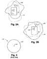
- a conventional wireless communications device that has a single antenna 200would have a radiation pattern as shown in a polar plot illustrated in FIG. 3 .
- the single antenna 200has an isotropic radiation pattern 210 illustrated with an isotropic gain line 220 of, for example, 0 dBi.
- radiation patternsare three dimensional, it is understood that the polar plots are merely two-dimensional representations. Thus, a polar plot may represent, for example, a cross section of a three-dimensional radiation pattern.
- the phrase “radiation pattern”is to be defined as including at least transmission patterns or reception patterns.
- the isotropic radiation pattern 210is a theoretical, ideal model occurring, for example, in the remote vacuum of space with a point source of radiation.
- FIG. 4shows another polar plot illustrating an example of a multipath radiation pattern 260 including a gain line 230 generated from the single antenna 200 .
- the gain line 230has been distorted due to multipath interference.
- points 240 , 250although equidistant from the single antenna, effectively see different radiation patterns in which the point 240 sees greater signal gain than the point 250 .
- a user of the conventional wireless communications devicetypically may need to physically move around in a random search for an improved signal (e.g., move from the point 250 to the point 240 without knowledge of the shape of the radiation pattern 260 ).
- Such physical translations of the conventional wireless communications deviceare not convenient and may not even be available under certain conditions such as, for example, when the user may not be free to move around.
- a first gain line 270is generated by the single antenna 200 at a first frequency f 1 and a second gain line 280 is generated by the single antenna 200 at a second frequency f 2 .
- the conventional wireless communications devicemay transmit and receive signals at different frequencies.
- the conventional wireless communications devicemay transmit at the first frequency f 1 and receive at the second frequency f 2 .
- the conventional wireless communications deviceeffectively experiences, for example, a radiation pattern for transmission as represented by the gain line 270 and a radiation pattern for reception as represented by the gain line 280 .
- the consequences during, for example, two-way wireless communications between the single antenna 200 and a point 290are further illustrated in FIG. 5 .
- the point 290 and the antenna 200effectively experience disparate radiation patterns depending upon whether the single antenna 200 is transmitting or receiving.
- the single antenna 200effectively experiences substantially more gain in receiving signals from the point 290 than in transmitting signals to the point 290 .
- the signal from the point 290is successfully received, the signal transmitted to the point 290 may be lost.
- the present inventionprovides a system and a method for receiving and transmitting information in a multipath environment including a first antenna, a second antenna, a switching module, a receiver module and a transmitter module.
- the switching moduleis adapted to couple the receiver module to one of the first antenna or the second antenna as a function of reception characteristics of the first antenna and the second antenna.
- the switching moduleis also adapted to couple the transmitter module to one of the first antenna or the second antenna as a function of transmission characteristics of the first antenna and the second antenna.
- the present inventionhas an advantage in that the wireless communications device provides the first antenna and the second antenna from which the wireless communications device can select to optimize transmission characteristics or reception characteristics.
- the present inventionhas an advantage in that the wireless communications device can automatically couple the transmitting module to the antenna that provides the best transmission characteristics.
- the present inventionalso has an advantage in that the wireless communications device can automatically couple the receiving module to the antenna that provides the best reception characteristics.
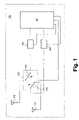
- FIG. 1shows a schematic representation of some components of a wireless communications device according to the present invention.
- FIG. 2Ais an illustration of a wireless device according to the present invention.
- FIG. 2Bis an illustration of a wireless device according to the present invention.
- FIG. 3shows a polar plot of an isotropic radiation pattern for a conventional antenna.
- FIG. 4shows a polar plot of a radiation pattern in a multipath environment for a conventional antenna.
- FIG. 5shows a polar plot of a radiation pattern at different frequencies in a multipath environment for a conventional antenna.
- FIG. 1illustrates an exemplary embodiment of a wireless communications system including a wireless communications device 100 according to the present invention.
- the wireless communications device 100may include, for example, a handheld wireless communications device, a mobile phone, a car phone, a cellular or a personal communications services (PCS) phone, a cordless phone, a laptop computer or other computing device with a wireless modem, a pager or a personal digital assistant (PDA).
- the wireless device 100may be digital or analog or some combination thereof. Indeed, the present invention also contemplates other forms of wireless communications devices known to one of ordinary skill in the art.
- the wireless communications device 100may include, for example, a first antenna 110 , a second antenna 120 , a switching module 130 , a transmitter module 140 , a receiver module 150 and a main controller 160 .
- the switching module 130may include, for example, a receiver switch 170 and a transmitter switch 180 .
- the main controller 160may include, for example, a mobile station modem (MSM) or other processor that is programmable.
- MSMmobile station modem
- the wireless communications device 100may also include other components (e.g., duplexers, diplexers, amplifiers, mixers, filters, oscillators, etc.) which are known to one of ordinary skill in the art and not shown or described further herein.
- the wireless communications device 100includes two antennas: the first antenna 110 in a first orientation, and the second antenna 120 oriented in a second orientation.
- the first antenna 110will be positioned in an orthogonal relationship or in another relationship that accentuates differing gain patterns from the first antenna 110 and the second antenna 120 .
- the first antenna 110is mounted such that the antenna extends, at least in part, outside the housing of the wireless communications device 100 , while the second antenna 120 is mounted inside the housing. It will be appreciated that other antenna mounting orientations and locations may be selected to support specific applications and aesthetic considerations.
- the wireless communications device 100transmits at frequency f 1 as shown in FIG. 2A and receives at frequency f 2 as shown in FIG. 2B .
- each antenna 110 , 120will have a different gain line at the frequency f 1 as compared to the gain line at the frequency f 2 .
- the first antenna 110has a radiation pattern with a gain line 115 when operating at the frequency f 1 as illustrated in FIG. 2A and a radiation pattern with a gain line 116 when operating at frequency f 2 as illustrated in FIG. 2B .
- the second antenna 120has a radiation pattern with a gain line 125 when operating at frequency f 1 as illustrated in FIG. 2A and a radiation pattern with a gain line 126 when operating at frequency f 2 as illustrated in FIG. 2B .
- the wireless communications device 100advantageously uses the difference in gain lines, such as, for example, between the gain line 115 and the gain line 125 or between the gain line 116 and the gain line 126 , to enhance operation of the wireless communications device 100 .
- the wireless communications device 100may determine which of the first antenna 110 or the second antenna 120 is better for transmitting or receiving a communications signal and may select the better antenna for current communications. In such a manner, more consistent signal quality may be obtained, which may, for example, reduce dropped calls, enable lower power usage, or permit faster data transmissions.
- gain linesmay vary in response, for example, to movements of the wireless communications device 100 or to changes in the environment, the wireless communications device 100 may continually determine and select the better antenna. Accordingly, the wireless communications device 100 may maintain a more consistent signal quality even when moving or when operated in an active, dynamic environment.
- the main controller 160is coupled to the transmitter module 140 , the receiver module 150 and the switching module 130 .
- the transmitter module 140is coupled to the transmitter switch 180 of the switching module 130 . Via the transmitter switch 180 , the transmitter module 140 can be coupled to one of the first antenna 110 or the second antenna 120 .
- the receiver module 150is coupled to the receiver switch 170 of the switching module 130 . Via the receiver switch 170 , the receiver module 160 can be coupled to one of the first antenna 110 or the second antenna 120 .
- the first antenna 110 and the second antenna 120can be disposed at an angle to each other.
- the first antenna 110is preferably disposed in a direction that is approximately orthogonal to the second antenna 120 . Since the orientation of an antenna affects its radiation pattern, the first antenna 110 and the second antenna 120 may have different radiation patterns. Thus, the second antenna 120 may provide an alternative radiation pattern for the wireless communications device 100 .
- the main controller 160receives a signal from a base station of a wireless communications network via the first antenna 110 or the second antenna 120 . Based on the signal, the main controller 160 sets the transmitting module 140 to transmit, for example, at a frequency f 1 and the receiving module 150 to receive at a frequency f 2 .
- the main controller 160can evaluate which antenna 110 , 120 provides the best reception characteristics at the frequency f 2 in the present environment, which may include multiple paths.
- the main controller 160can also evaluate which antenna 110 , 120 provides the best transmission characteristics (e.g., signal strength, clarity, bit error rate, etc.) at the frequency f 1 in the present environment.
- the evaluationscan take place periodically or aperiodically (e.g., triggered by a particular condition). Based on the evaluations, the main controller 160 can control the switching module 130 to switch the transmitter module 140 or the receiver module 150 to the appropriate antenna 110 , 120 .
- the main controller 160may determine, for example, that for the assigned channel at frequency f 2 , the first antenna 110 provides superior reception to the second antenna 120 in the present environment. Thus, the main controller 160 sends a control signal to the switching module 130 that causes the first switch 170 to couple the receiver module 150 to the first antenna 110 .
- the main controller 160may also determine, for example, that for the assigned channel at frequency f 1 , the first antenna 110 provides superior transmission in the present environment. Thus, the main controller 160 sends a control signal to the switching module 130 that causes the second switch 180 to couple the transmitter module 140 to the first antenna 110 .
- the receiver module 150is coupled to, for example, the first antenna 110 via the first switch 170 of the switching module 130 .
- the main controller 160monitors the reception characteristics of the first antenna 110 . If the reception characteristics become poor (e.g., the bit error rate exceeds or is nearing an applicable error threshold), then the main controller 160 tests the reception characteristics of the second antenna 110 .
- the main controller 160may control the switching module 130 such that the first switch 170 couples the receiver module 150 to the second antenna 120 in order to evaluate the reception characteristics of the second antenna 120 . This can be accomplished relatively quickly. For example, if the reception characteristic of the second antenna 120 is evaluated based on, for example, the error bit rate of the second antenna 120 , then an evaluation can be determined even on a bit-by-bit basis.
- the main controller 160may keep the receiver module 150 coupled to the second antenna 120 .
- the main controller 160then monitors the reception characteristics of the second antenna 120 .
- the main controller 160may control the switching module such that the first switch maintains the coupling between the receiver module 150 and the first antenna 110 .
- a similar proceduremay be implemented by the main controller 160 in monitoring the transmission characteristics of the antennas 110 , 120 .
- the main controller 160may monitor transmission characteristics (e.g., signal strength) via feedback from the base station.
- transmission characteristicse.g., signal strength
- the main controller 160can test the transmission characteristics of the other antenna, for example, the first antenna 110 , by coupling the transmitter module 140 to the first antenna 110 .
- the main controller 160may use feedback information from the base station (e.g., closed loop power control).
- the main controller 160may control the switching module such that the second switch 180 couples the transmitter module 140 to the second antenna 120 .
- the main controller 160can then attempt to match the reception characteristics with the new transmission characteristics.
- the main controller 160tests the reception characteristics of the first antenna 110 and the second antenna 120 to evaluate which one has the reception characteristic, in particular, for this example, the strength parameter, closest to the particular quantity.
- the antenna 110 , 120 selecteddoes not necessarily have, for example, the largest strength parameter, but only the closest matched strength parameter.
- the main controller 160maintains a list of base stations in range for at least one of the first antenna 110 and the second antenna 120 .
- This listcan be compiled when the wireless communications device 100 receives signals from all the base stations in range of the wireless communications device 100 during, for example, a registration process or other initial process.
- the listcan be updated periodically or aperiodically (e.g., triggered by a particular condition or event). Accordingly, if the transmission characteristics of the antenna presently being used for transmission becomes poor, then the main controller 160 can test the transmission characteristics for each of the antennas with each of the base stations on the list. Based upon such tests, a switch in antenna or base station may follow. If the reception characteristics of the antenna presently being used for reception becomes poor, then the main controller 160 can test the reception characteristics for each of the antennas with each of the base stations on the list. Based upon such tests, a switch in antenna or base station may follow.
Landscapes
- Engineering & Computer Science (AREA)
- Computer Networks & Wireless Communication (AREA)
- Signal Processing (AREA)
- Mobile Radio Communication Systems (AREA)
- Radio Transmission System (AREA)
- Variable-Direction Aerials And Aerial Arrays (AREA)
- Circuits Of Receivers In General (AREA)
Abstract
Description
Claims (20)
Priority Applications (1)
| Application Number | Priority Date | Filing Date | Title |
|---|---|---|---|
| US11/459,518US7447525B2 (en) | 2001-07-10 | 2006-07-24 | System and method for receiving and transmitting information in a multipath environment |
Applications Claiming Priority (2)
| Application Number | Priority Date | Filing Date | Title |
|---|---|---|---|
| US09/902,035US7103382B2 (en) | 2001-07-10 | 2001-07-10 | System and method for receiving and transmitting information in a multipath environment |
| US11/459,518US7447525B2 (en) | 2001-07-10 | 2006-07-24 | System and method for receiving and transmitting information in a multipath environment |
Related Parent Applications (1)
| Application Number | Title | Priority Date | Filing Date |
|---|---|---|---|
| US09/902,035ContinuationUS7103382B2 (en) | 2001-07-10 | 2001-07-10 | System and method for receiving and transmitting information in a multipath environment |
Publications (2)
| Publication Number | Publication Date |
|---|---|
| US20060252383A1 US20060252383A1 (en) | 2006-11-09 |
| US7447525B2true US7447525B2 (en) | 2008-11-04 |
Family
ID=25415220
Family Applications (3)
| Application Number | Title | Priority Date | Filing Date |
|---|---|---|---|
| US09/902,035Expired - Fee RelatedUS7103382B2 (en) | 2001-07-10 | 2001-07-10 | System and method for receiving and transmitting information in a multipath environment |
| US10/080,948Expired - Fee RelatedUS7035654B2 (en) | 2001-07-10 | 2002-02-21 | System and method for providing GPS-enabled wireless communications |
| US11/459,518Expired - Fee RelatedUS7447525B2 (en) | 2001-07-10 | 2006-07-24 | System and method for receiving and transmitting information in a multipath environment |
Family Applications Before (2)
| Application Number | Title | Priority Date | Filing Date |
|---|---|---|---|
| US09/902,035Expired - Fee RelatedUS7103382B2 (en) | 2001-07-10 | 2001-07-10 | System and method for receiving and transmitting information in a multipath environment |
| US10/080,948Expired - Fee RelatedUS7035654B2 (en) | 2001-07-10 | 2002-02-21 | System and method for providing GPS-enabled wireless communications |
Country Status (8)
| Country | Link |
|---|---|
| US (3) | US7103382B2 (en) |
| EP (1) | EP1405439B1 (en) |
| JP (1) | JP2004537207A (en) |
| CN (2) | CN101047413B (en) |
| AT (1) | ATE321381T1 (en) |
| DE (1) | DE60210083T2 (en) |
| ES (1) | ES2259711T3 (en) |
| WO (1) | WO2003007502A1 (en) |
Cited By (1)
| Publication number | Priority date | Publication date | Assignee | Title |
|---|---|---|---|---|
| US20100184386A1 (en)* | 2007-06-27 | 2010-07-22 | Max Ward Muterspaugh | Apparatus and method for controlling a signal |
Families Citing this family (32)
| Publication number | Priority date | Publication date | Assignee | Title |
|---|---|---|---|---|
| US7181171B2 (en)* | 2001-07-20 | 2007-02-20 | Kyocera Wireless Corp. | System and method for providing auxiliary reception in a wireless communications system |
| JP3744883B2 (en)* | 2002-06-05 | 2006-02-15 | 日本電気株式会社 | Mobile phone, analysis device built in the same, and analysis method thereof |
| JP4540936B2 (en)* | 2003-02-10 | 2010-09-08 | 富士通株式会社 | Mobile terminal |
| US6924766B2 (en) | 2003-04-03 | 2005-08-02 | Kyocera Wireless Corp. | Wireless telephone antenna diversity system |
| EP1627446A1 (en)* | 2003-05-16 | 2006-02-22 | Philips Intellectual Property & Standards GmbH | Switchable multiband antenna for the high-frequency and microwave range |
| JP3915763B2 (en)* | 2003-09-19 | 2007-05-16 | 株式会社日立製作所 | Mobile device |
| KR100600707B1 (en) | 2004-07-23 | 2006-07-14 | 삼성전자주식회사 | Wireless signal reception method considering multipath |
| US7627296B2 (en) | 2004-10-18 | 2009-12-01 | Research In Motion Limited | Method of controlling a plurality of internal antennas in a mobile communication device |
| US7176835B2 (en)* | 2005-01-28 | 2007-02-13 | Motorola, Inc. | Selecting an optimal antenna in a GPS receiver and methods thereof |
| US7890133B2 (en)* | 2005-02-09 | 2011-02-15 | Research In Motion Limited | Mobile wireless communications device providing pattern/frequency control features and related methods |
| JP2008538886A (en)* | 2005-04-28 | 2008-11-06 | エヌエックスピー ビー ヴィ | Wireless device |
| US7729714B2 (en)* | 2005-12-20 | 2010-06-01 | Qualcomm Incorporated | Method and apparatus for reverse link transmit beam-forming |
| TWI275203B (en)* | 2005-12-30 | 2007-03-01 | Inventec Appliances Corp | Antenna system of GPS receiver and switching method of antenna |
| EP1976131A4 (en)* | 2006-01-20 | 2011-08-03 | Panasonic Corp | MOBILE TERMINAL DEVICE |
| TW200744332A (en)* | 2006-05-30 | 2007-12-01 | Benq Corp | Method and apparatus of receiving signals and wireless multimode wideband receiver |
| US8085786B2 (en)* | 2007-03-16 | 2011-12-27 | Qualcomm Incorporated | H-ARQ throughput optimization by prioritized decoding |
| US20090191897A1 (en)* | 2008-01-24 | 2009-07-30 | Cortxt, Inc. | Environment Characterization for Mobile Devices |
| CN101778444B (en)* | 2009-01-12 | 2013-04-24 | 瑞昱半导体股份有限公司 | Transmission path selection device and method in wireless network |
| KR20100107801A (en)* | 2009-03-26 | 2010-10-06 | 삼성전자주식회사 | Apparatus and method for antenna selection in wireless communication system |
| US9184821B2 (en)* | 2009-11-04 | 2015-11-10 | Nec Corporation | Control method of radio communication system, radio communication system, and radio communication apparatus |
| JP5356185B2 (en)* | 2009-11-05 | 2013-12-04 | 前田金属工業株式会社 | Antenna switching method for wireless communication system |
| US8874041B2 (en) | 2011-10-03 | 2014-10-28 | Apple Inc. | Electronic device with service acquisition antenna switching |
| US9344174B2 (en) | 2012-05-21 | 2016-05-17 | Qualcomm Incorporated | Systems, apparatus, and methods for antenna selection |
| US9070974B2 (en) | 2012-05-21 | 2015-06-30 | Qualcomm Incorporated | Antenna switching devices, methods, and systems for simultaneous communication |
| CN104617993B (en)* | 2014-12-23 | 2019-02-05 | 武汉正维电子技术有限公司 | A kind of orthogonal double antenna micro power radio communication method and apparatus |
| US10615499B2 (en) | 2015-01-14 | 2020-04-07 | Skywave Mobile Communications Inc. | Dual role antenna assembly |
| CN106539569A (en)* | 2015-12-10 | 2017-03-29 | 悦享趋势科技(北京)有限责任公司 | Wearable physiological monitoring equipment and its antenna system |
| US9947993B2 (en)* | 2016-08-12 | 2018-04-17 | Microsoft Technology Licensing, Llc | Antenna stack |
| CN106299700B (en)* | 2016-09-12 | 2018-04-20 | 广东欧珀移动通信有限公司 | Antenna structure and mobile terminal |
| CN108965560B (en)* | 2018-07-16 | 2020-04-24 | 厦门美图移动科技有限公司 | Antenna state detection method and terminal equipment |
| KR20200121176A (en)* | 2019-04-15 | 2020-10-23 | 삼성전자주식회사 | Positioning signal receiver and operating method thereof |
| US11635528B2 (en) | 2020-08-12 | 2023-04-25 | Rockwell Collins, Inc. | GPS receiver module |
Citations (28)
| Publication number | Priority date | Publication date | Assignee | Title |
|---|---|---|---|---|
| US4513412A (en) | 1983-04-25 | 1985-04-23 | At&T Bell Laboratories | Time division adaptive retransmission technique for portable radio telephones |
| US4780885A (en) | 1982-12-01 | 1988-10-25 | Paul Haim D | Frequency management system |
| EP0364190A2 (en) | 1988-10-12 | 1990-04-18 | Sumitomo Electric Industries, Ltd. | Diversity transmission and reception method and equipment |
| US5095535A (en) | 1988-07-28 | 1992-03-10 | Motorola, Inc. | High bit rate communication system for overcoming multipath |
| EP0624007A2 (en) | 1993-05-06 | 1994-11-09 | NCR International, Inc. | Wireless communication system having antenna diversity |
| EP0740430A2 (en) | 1995-04-27 | 1996-10-30 | Sharp Kabushiki Kaisha | Diversity radio communication system |
| US5657325A (en) | 1995-03-31 | 1997-08-12 | Lucent Technologies Inc. | Transmitter and method for transmitting information packets with incremental redundancy |
| EP0844801A2 (en) | 1996-11-25 | 1998-05-27 | Nec Corporation | Cellsite station having switcher units to implement intra-cell handover |
| US5822699A (en) | 1996-01-30 | 1998-10-13 | Motorola, Inc. | Method and apparatus for maintaining call in a communication system |
| US6002672A (en)* | 1996-10-25 | 1999-12-14 | Nortel Networks Corporation | Diversity antenna selection |
| US6021317A (en)* | 1997-04-30 | 2000-02-01 | Ericsson Inc. | Dual antenna radiotelephone systems including an antenna-management matrix switch and associated methods of operation |
| US6052605A (en)* | 1997-03-31 | 2000-04-18 | Radio Frequency Systems, Inc. | Continuous interference assessment and avoidance in a land mobile radio system |
| US6108525A (en) | 1997-08-06 | 2000-08-22 | Nec Corporation | Transceiver |
| US6137830A (en) | 1998-01-16 | 2000-10-24 | Motorola | Measuring bit error rate performance of a receiver by the receiver and conveying measurement acoustically |
| GB2350978A (en) | 1998-12-28 | 2000-12-13 | Toshiba Kk | Cdma mobile radio terminal |
| EP1063789A1 (en) | 1999-06-23 | 2000-12-27 | Sony International (Europe) GmbH | Transmit and receiving antenna diversity |
| US6178323B1 (en) | 1997-11-07 | 2001-01-23 | Nec Corporation | System and method for determining a tentative master of a radio conference system |
| JP2001077736A (en) | 1999-09-02 | 2001-03-23 | Matsushita Electric Ind Co Ltd | Communication device |
| US6212368B1 (en) | 1998-05-27 | 2001-04-03 | Ericsson Inc. | Measurement techniques for diversity and inter-frequency mobile assisted handoff (MAHO) |
| WO2001041330A1 (en) | 1999-11-30 | 2001-06-07 | Fraunhofer-Gesellschaft zur Förderung der angewandten Forschung e.V. | Dect transmitting-receiving terminal and method for communicating between a dect transmitting-receiving terminal and a dect base station |
| US6393287B1 (en) | 1999-05-24 | 2002-05-21 | Nec Corporation | System for switching speech channel between loosely couple radio base stations |
| US6456245B1 (en) | 2000-12-13 | 2002-09-24 | Magis Networks, Inc. | Card-based diversity antenna structure for wireless communications |
| US6532369B1 (en) | 1999-08-20 | 2003-03-11 | Lucent Technologies Inc. | System and method for mobile controlled direct mode wireless local calling |
| US20030073410A1 (en)* | 2000-04-10 | 2003-04-17 | Ari Hottinen | Data transmission method and radio system |
| US6594473B1 (en)* | 1999-05-28 | 2003-07-15 | Texas Instruments Incorporated | Wireless system with transmitter having multiple transmit antennas and combining open loop and closed loop transmit diversities |
| US6633759B1 (en) | 1999-09-30 | 2003-10-14 | Kabushiki Kaisha Toshiba | Communication system, and mobile communication device, portable information processing device, and data communication method used in the system |
| US6694131B1 (en) | 2001-02-21 | 2004-02-17 | Mitsubishi Electric Corporation | Method and apparatus for adaptive image rejection |
| US20040213178A1 (en)* | 2001-01-26 | 2004-10-28 | Dell Products L.P. | Reducing multipath fade of RF signals in a wireless data application |
Family Cites Families (18)
| Publication number | Priority date | Publication date | Assignee | Title |
|---|---|---|---|---|
| US3628149A (en)* | 1968-12-19 | 1971-12-14 | Bell Telephone Labor Inc | Diversity switch for digital transmission |
| JPH0778532B2 (en) | 1988-06-20 | 1995-08-23 | 日本無線株式会社 | Diversity reception GPS receiver |
| US5561673A (en) | 1993-04-16 | 1996-10-01 | Matsushita Electric Industrial Co., Ltd. | Antenna switched diversity reciever |
| KR960009446B1 (en) | 1993-12-23 | 1996-07-19 | Hyundai Electronics Ind | A diversity device of gps antenna |
| US5594454A (en)* | 1994-04-13 | 1997-01-14 | The Johns Hopkins University | Global positioning system (GPS) linked satellite and missile communication systems |
| CN1092847C (en)* | 1994-09-14 | 2002-10-16 | 皇家菲利浦电子有限公司 | Radio transmission systems and radio equipment for use with such systems |
| CA2213848A1 (en) | 1995-03-20 | 1996-09-26 | Edmund J. Ring | Dual frequency antenna with integral diplexer |
| FI105515B (en)* | 1995-05-24 | 2000-08-31 | Nokia Networks Oy | A method for accelerating handoff and a cellular radio system |
| EP0857359A4 (en) | 1995-10-27 | 1999-01-27 | Geotek Communications Inc | A linear diversity antenna |
| US5945944A (en)* | 1996-03-08 | 1999-08-31 | Snaptrack, Inc. | Method and apparatus for determining time for GPS receivers |
| US6049705A (en) | 1998-02-03 | 2000-04-11 | Ericsson Inc. | Diversity for mobile terminals |
| US5986609A (en) | 1998-06-03 | 1999-11-16 | Ericsson Inc. | Multiple frequency band antenna |
| GB9913697D0 (en) | 1999-06-11 | 1999-08-11 | Adaptive Broadband Ltd | Dynamic channel allocation in a wireless network |
| EP1069706B1 (en)* | 1999-06-23 | 2016-10-05 | Texas Instruments Inc. | Radio communications apparatus and method with a steerable directional beam antenna |
| JP2001284943A (en) | 2000-03-30 | 2001-10-12 | Sony Corp | Equipment and method for radio communication |
| US6542119B2 (en)* | 2000-05-23 | 2003-04-01 | Varitek Industries, Inc. | GPS antenna array |
| GB0013148D0 (en)* | 2000-05-31 | 2000-07-19 | Koninkl Philips Electronics Nv | A method of despreading GPS stread spectrum signals |
| JP2001356159A (en) | 2000-06-15 | 2001-12-26 | Seiko Epson Corp | GPS receiving system |
- 2001
- 2001-07-10USUS09/902,035patent/US7103382B2/ennot_activeExpired - Fee Related
- 2002
- 2002-02-21USUS10/080,948patent/US7035654B2/ennot_activeExpired - Fee Related
- 2002-07-10EPEP02743511Apatent/EP1405439B1/ennot_activeExpired - Lifetime
- 2002-07-10CNCN2006101272456Apatent/CN101047413B/ennot_activeExpired - Fee Related
- 2002-07-10DEDE60210083Tpatent/DE60210083T2/ennot_activeExpired - Lifetime
- 2002-07-10WOPCT/IB2002/002721patent/WO2003007502A1/enactiveIP Right Grant
- 2002-07-10JPJP2003513147Apatent/JP2004537207A/enactivePending
- 2002-07-10ATAT02743511Tpatent/ATE321381T1/ennot_activeIP Right Cessation
- 2002-07-10CNCNB028136780Apatent/CN1305231C/ennot_activeExpired - Fee Related
- 2002-07-10ESES02743511Tpatent/ES2259711T3/ennot_activeExpired - Lifetime
- 2006
- 2006-07-24USUS11/459,518patent/US7447525B2/ennot_activeExpired - Fee Related
Patent Citations (30)
| Publication number | Priority date | Publication date | Assignee | Title |
|---|---|---|---|---|
| US4780885A (en) | 1982-12-01 | 1988-10-25 | Paul Haim D | Frequency management system |
| US4513412A (en) | 1983-04-25 | 1985-04-23 | At&T Bell Laboratories | Time division adaptive retransmission technique for portable radio telephones |
| US5095535A (en) | 1988-07-28 | 1992-03-10 | Motorola, Inc. | High bit rate communication system for overcoming multipath |
| EP0364190A2 (en) | 1988-10-12 | 1990-04-18 | Sumitomo Electric Industries, Ltd. | Diversity transmission and reception method and equipment |
| EP0624007A2 (en) | 1993-05-06 | 1994-11-09 | NCR International, Inc. | Wireless communication system having antenna diversity |
| US5491723A (en) | 1993-05-06 | 1996-02-13 | Ncr Corporation | Wireless communication system having antenna diversity |
| US5657325A (en) | 1995-03-31 | 1997-08-12 | Lucent Technologies Inc. | Transmitter and method for transmitting information packets with incremental redundancy |
| EP0740430A2 (en) | 1995-04-27 | 1996-10-30 | Sharp Kabushiki Kaisha | Diversity radio communication system |
| US5822699A (en) | 1996-01-30 | 1998-10-13 | Motorola, Inc. | Method and apparatus for maintaining call in a communication system |
| US6002672A (en)* | 1996-10-25 | 1999-12-14 | Nortel Networks Corporation | Diversity antenna selection |
| EP0844801A2 (en) | 1996-11-25 | 1998-05-27 | Nec Corporation | Cellsite station having switcher units to implement intra-cell handover |
| US6052605A (en)* | 1997-03-31 | 2000-04-18 | Radio Frequency Systems, Inc. | Continuous interference assessment and avoidance in a land mobile radio system |
| US6021317A (en)* | 1997-04-30 | 2000-02-01 | Ericsson Inc. | Dual antenna radiotelephone systems including an antenna-management matrix switch and associated methods of operation |
| US6108525A (en) | 1997-08-06 | 2000-08-22 | Nec Corporation | Transceiver |
| US6178323B1 (en) | 1997-11-07 | 2001-01-23 | Nec Corporation | System and method for determining a tentative master of a radio conference system |
| US6137830A (en) | 1998-01-16 | 2000-10-24 | Motorola | Measuring bit error rate performance of a receiver by the receiver and conveying measurement acoustically |
| US6212368B1 (en) | 1998-05-27 | 2001-04-03 | Ericsson Inc. | Measurement techniques for diversity and inter-frequency mobile assisted handoff (MAHO) |
| GB2350978A (en) | 1998-12-28 | 2000-12-13 | Toshiba Kk | Cdma mobile radio terminal |
| US6393287B1 (en) | 1999-05-24 | 2002-05-21 | Nec Corporation | System for switching speech channel between loosely couple radio base stations |
| US6594473B1 (en)* | 1999-05-28 | 2003-07-15 | Texas Instruments Incorporated | Wireless system with transmitter having multiple transmit antennas and combining open loop and closed loop transmit diversities |
| EP1063789A1 (en) | 1999-06-23 | 2000-12-27 | Sony International (Europe) GmbH | Transmit and receiving antenna diversity |
| US6532369B1 (en) | 1999-08-20 | 2003-03-11 | Lucent Technologies Inc. | System and method for mobile controlled direct mode wireless local calling |
| JP2001077736A (en) | 1999-09-02 | 2001-03-23 | Matsushita Electric Ind Co Ltd | Communication device |
| GB2358769A (en) | 1999-09-02 | 2001-08-01 | Matsushita Electric Industrial Co Ltd | Communications Apparatus |
| US6633759B1 (en) | 1999-09-30 | 2003-10-14 | Kabushiki Kaisha Toshiba | Communication system, and mobile communication device, portable information processing device, and data communication method used in the system |
| WO2001041330A1 (en) | 1999-11-30 | 2001-06-07 | Fraunhofer-Gesellschaft zur Förderung der angewandten Forschung e.V. | Dect transmitting-receiving terminal and method for communicating between a dect transmitting-receiving terminal and a dect base station |
| US20030073410A1 (en)* | 2000-04-10 | 2003-04-17 | Ari Hottinen | Data transmission method and radio system |
| US6456245B1 (en) | 2000-12-13 | 2002-09-24 | Magis Networks, Inc. | Card-based diversity antenna structure for wireless communications |
| US20040213178A1 (en)* | 2001-01-26 | 2004-10-28 | Dell Products L.P. | Reducing multipath fade of RF signals in a wireless data application |
| US6694131B1 (en) | 2001-02-21 | 2004-02-17 | Mitsubishi Electric Corporation | Method and apparatus for adaptive image rejection |
Non-Patent Citations (1)
| Title |
|---|
| Akaiwa Y, "Antenna selection diversity for framed digital signal transmission in mobile radio channel" IEEE XP010086167, pp. 470-472, 1989. |
Cited By (2)
| Publication number | Priority date | Publication date | Assignee | Title |
|---|---|---|---|---|
| US20100184386A1 (en)* | 2007-06-27 | 2010-07-22 | Max Ward Muterspaugh | Apparatus and method for controlling a signal |
| US8515482B2 (en)* | 2007-06-27 | 2013-08-20 | Thomson Licensing | Apparatus and method for controlling a signal |
Also Published As
| Publication number | Publication date |
|---|---|
| US7103382B2 (en) | 2006-09-05 |
| EP1405439B1 (en) | 2006-03-22 |
| US7035654B2 (en) | 2006-04-25 |
| US20030013470A1 (en) | 2003-01-16 |
| JP2004537207A (en) | 2004-12-09 |
| CN1305231C (en) | 2007-03-14 |
| EP1405439A1 (en) | 2004-04-07 |
| WO2003007502A1 (en) | 2003-01-23 |
| ATE321381T1 (en) | 2006-04-15 |
| ES2259711T3 (en) | 2006-10-16 |
| US20030013469A1 (en) | 2003-01-16 |
| US20060252383A1 (en) | 2006-11-09 |
| CN101047413B (en) | 2010-08-18 |
| DE60210083T2 (en) | 2006-10-12 |
| CN1524356A (en) | 2004-08-25 |
| CN101047413A (en) | 2007-10-03 |
| DE60210083D1 (en) | 2006-05-11 |
Similar Documents
| Publication | Publication Date | Title |
|---|---|---|
| US7447525B2 (en) | System and method for receiving and transmitting information in a multipath environment | |
| EP1476961B1 (en) | System and method for providing gps-enabled wireless communications | |
| US8717930B2 (en) | Wireless communication system | |
| US20080111748A1 (en) | Antenna system having plural selectable antenna feed points and method of operation thereof | |
| US20040114535A1 (en) | Method and apparatus for antenna steering for WLAN | |
| US20050037822A1 (en) | Antenna steering method and apparatus for an 802.11 station | |
| JP2004537207A5 (en) | ||
| EP1554900B1 (en) | Method and apparatus for antenna steering for wlan | |
| US20230300690A1 (en) | Local Coordinated Communications for User Equipment Devices | |
| US20060052069A1 (en) | Communication apparatus | |
| US20230268668A1 (en) | Electronic Devices with Polarization Management Capabilities | |
| US10091742B2 (en) | Wireless communication device | |
| KR20050057449A (en) | Radio communication system, radio communication device, and radio communication method | |
| JP3886445B2 (en) | Wireless LAN access point and method of operating the same | |
| HK1081040B (en) | Method and apparatus for antenna steering for wlan |
Legal Events
| Date | Code | Title | Description |
|---|---|---|---|
| AS | Assignment | Owner name:KYOCERA WIRELESS CORP., CALIFORNIA Free format text:ASSIGNMENT OF ASSIGNORS INTEREST;ASSIGNOR:FORRESTER, TIMOTHY D.;REEL/FRAME:018717/0129 Effective date:20010926 | |
| STCF | Information on status: patent grant | Free format text:PATENTED CASE | |
| AS | Assignment | Owner name:KYOCERA CORPORATION,JAPAN Free format text:ASSIGNMENT OF ASSIGNORS INTEREST;ASSIGNOR:KYOCERA WIRELESS CORP.;REEL/FRAME:024170/0005 Effective date:20100326 Owner name:KYOCERA CORPORATION, JAPAN Free format text:ASSIGNMENT OF ASSIGNORS INTEREST;ASSIGNOR:KYOCERA WIRELESS CORP.;REEL/FRAME:024170/0005 Effective date:20100326 | |
| FPAY | Fee payment | Year of fee payment:4 | |
| FPAY | Fee payment | Year of fee payment:8 | |
| SULP | Surcharge for late payment | Year of fee payment:7 | |
| FEPP | Fee payment procedure | Free format text:MAINTENANCE FEE REMINDER MAILED (ORIGINAL EVENT CODE: REM.); ENTITY STATUS OF PATENT OWNER: LARGE ENTITY | |
| LAPS | Lapse for failure to pay maintenance fees | Free format text:PATENT EXPIRED FOR FAILURE TO PAY MAINTENANCE FEES (ORIGINAL EVENT CODE: EXP.); ENTITY STATUS OF PATENT OWNER: LARGE ENTITY | |
| STCH | Information on status: patent discontinuation | Free format text:PATENT EXPIRED DUE TO NONPAYMENT OF MAINTENANCE FEES UNDER 37 CFR 1.362 | |
| FP | Lapsed due to failure to pay maintenance fee | Effective date:20201104 |