US7447380B2 - Efficient method for creating a viewpoint from plurality of images - Google Patents
Efficient method for creating a viewpoint from plurality of imagesDownload PDFInfo
- Publication number
- US7447380B2 US7447380B2US10/660,751US66075103AUS7447380B2US 7447380 B2US7447380 B2US 7447380B2US 66075103 AUS66075103 AUS 66075103AUS 7447380 B2US7447380 B2US 7447380B2
- Authority
- US
- United States
- Prior art keywords
- image
- images
- correspondence
- background
- real
- Prior art date
- Legal status (The legal status is an assumption and is not a legal conclusion. Google has not performed a legal analysis and makes no representation as to the accuracy of the status listed.)
- Expired - Lifetime, expires
Links
Images


Classifications
- G—PHYSICS
- G06—COMPUTING OR CALCULATING; COUNTING
- G06T—IMAGE DATA PROCESSING OR GENERATION, IN GENERAL
- G06T7/00—Image analysis
- G06T7/97—Determining parameters from multiple pictures
Definitions
- the present inventionrelates to the field of imagery in multimedia, video (including interactive, immersive, Internet and networked streaming video), virtual reality, telepresence and television. More particularly, the present invention relates to a method by which an image from an uncaptured viewpoint, caused by a change in observation position that provides a new line of sight, is efficiently created from a plurality of captured images.
- PPSBMper-pixel search based matching
- the selective techniques that limit processing time for PPSBMoften employ temporal change detection.
- change detection techniquesdetect changes in many areas that are part of the background. For example, the shadows of moving foreground objects that are usually projected onto background objects are detected. As a result, these photogrametric changes give rise to significantly more processing than is necessary.
- interior points of objectsare not detected using conventional techniques, leading to errors in matching that subsequently lead to errors in the correspondences.
- PPSBMtends to give sparse results (few correspondences with respect to the number of pixels in the image), whereas dense results (up to the number of pixels in the image) are needed.
- PPSBMcan give noisy results inside objects where contrast is low or features are lacking.
- the present inventionsatisfies, to a great extent, the foregoing and other needs not currently satisfied by existing techniques.
- This resultis achieved, in an exemplary embodiment, by a method wherein multi-image correspondence of a scene's background, which is free of movable objects is determined in advance, a multiple of foreground objects is detected, and correspondence fields for those detected objects are found and joined with the background correspondences, all in real time.
- two or more imagesare obtained simultaneously from one or more pairs of cameras, each camera of which is located in differently, but with significantly overlapping views of a scene.
- the camerasare stationary and, in advance of processing, one or more pair of images are obtained.
- a background scene free of movable object(s)is imaged.
- an original set of correspondencesis determined. This set is called the “background correspondence field” for the said camera pair.
- the background correspondence fieldis used thereafter in real-time to detect movable objects that are not in the previously determined background scene, and is also used in later real-time steps.
- Each detection of a movable objectis spatially grouped and assigned a distance value based on its position relative to the background scene. These distance values are used to create new correspondences, which are incorporated into the original of background correspondence field. In an iterative manner, the new correspondences are further refined. This refinement consists of one or more steps of determining the quality of the new correspondences and adjusting the object parameters to improve that quality.
- the resulting correspondence field(s)become final, and along with the geometric relationship of the cameras are used to generate a warping field.
- Said warping fieldis then applied to one or more of the real-time images captured from an actual fixed camera. In this regard, the result of applying the warping field is to generate an uncaptured viewpoint image.
- the above-mentioned method of the present inventiondramatically simplifies conventional correspondence matching from a per-pixel based search operation to a warping and an image differencing operation that is easily performed on existing digital video processing devices or the like, for example, and in real time.
- Real-time processingis an important advantage, since a primary purpose for determining image correspondence data is its use in generating virtual reality imagery, or a visual telepresence experience by users who are viewing an actual scene in real-time.
- the method of the present inventionprovides a high degree of satisfaction in correspondence results, such that any matching errors result in visually pleasing images that are adequate for a number of useful applications. This is because the correspondences always agree with those that a realistic three-dimensional scene object would project.
- the method of the present inventionproduces a dense correspondence field without additional processing steps.
- a Correspondence Fieldthat is generated on the basis of images of a scene where there are no movable objects present.
- a Correspondence Fieldthat has nearly as many, or just as many elements as there are pixels in one of the images.
- a Differenced Imageis the result of applying the difference operation to two images, or “differencing” them.
- a regular array of point valuesusually representing brightness and color values as samples of a picture.
- an imageis an array of values, still registered with the image frame, but representing quantities other than brightness or color, such as correspondence or image difference.
- An element of a digital image, or Picture Elementusually corresponding to one sample at one spatial location.
- a process for finding correspondences between imagesthat selects pixels in one image and searches for the best match in the second image.
- a selection processmay cause the search to avoid some or many pixels.
- the visual worldusually limited as can be viewed from some viewpoint or in some area.
- a camera position that is not the position of an actual cameraalso called a “novel viewpoint”.
- Nounsame as Viewpoint, Verb: to see or create an image.
- An image captured from a viewpointor one that appears to be captured from a viewpoint.
- a regular array of two-dimensional vectorsthat describe the way that one image is to be distorted, on a pixel-by-pixel basis, to create a second image.
- each vector of the fieldis used to acquire image values from one image and deposit them into another.
- the Warping processis the collective application of the entire field of vectors.
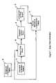
- FIG. 1is a flow chart describing a method for efficiently creating an uncaptured viewpoint from a plurality of images, in accordance with a preferred embodiment of the present invention.
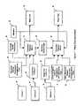
- FIG. 2is a block diagram of exemplary devices useful to generate an uncaptured viewpoint image, in accordance with FIG. 1 .
- FIG. 3is a diagram showing a preferred orientation of one or more cameras employed in the present invention.
- FIG. 4is a flow diagram showing a process for differencing a warped image and a captured image.
- FIG. 5is a flow diagram showing a process for generation of a correspondence field for a body of connected components.
- FIG. 6is a flow diagram showing a process for generation of refined correspondence field(s).
- FIG. 7is a flow diagram showing a process for generation of warp fields which will subsequently be used to warp a captured image to create an novel viewpoint image.
- the present inventionis directed to an efficient method for generating an uncaptured viewpoint derived from a plurality of captured images.
- the methodignores photogrametric changes in an image in favor of true three-dimensional changes in the scene.
- the present inventionis more efficient than conventional techniques, such as per-pixel search-based matching, in that direct detection and heuristically implied correspondences provide nearly correct results. These results are usually very adequate data for subsequent viewpoint generation steps. When they are in error, the results will still produce adequate visual displays for many applications such as (but not limited to) real-time virtual telepresence in indoor and outdoor scenes for entertainment, tourism, and security.
- FIG. 1there is shown a flow chart of the method of the present invention.
- a background scenepreferably free of movable object(s) is imaged (S 10 ).
- Each such pairs of imagesare obtained, simultaneously, from one or more pairs of cameras, each camera of a pair located differently, but with significantly overlapping views of a scene.
- the camerasare preferably stationary in their respective locations.
- a dense correspondence field of the background sceneis also determined in advance for each pair (S 11 ). If more than one pair shares a camera, dense correspondence fields are determined for all such pairs.
- imageare acquired as at S 12 .
- the original set of correspondence data for the backgroundis used to detect movable objects that are not in the background scene previously determined, as at S 12 .
- Thisis accomplished by using the correspondence data as a warp field, warping one image so as to come into correspondence with the other image, and differencing the other said image and the warped one.
- a thresholdis applied to the resulting difference values resulting in a binary image where all pixels above the threshold are detections. These detections are spatially grouped. All of these detection steps occur within the step S 13 .
- Each spatially grouped detectionis assigned a distance value based on the group's position relative to the background scene.
- the distance value of each groupis used in turn to create new correspondence data, which are integrated into the original set of correspondences as in S 14 .
- the resulting correspondence dataare again refined and used as a warp field. Again, images are differenced and detections indicate remaining errors in estimating correspondences as in S 15 .
- the refinement of the correspondence fieldcan repeat (iterate) until either a sufficiently small residual error is achieved, or a specified amount of time has elapsed as in S 16 and S 17 .
- the final correspondence fieldis thus used (along with other information) in the formation of a warping field (S 18 ), which in turn is used to warp an existing real image or images to generate an uncaptured viewpoint image (S 19 ). At least one image is warped to generate the uncaptured viewpoint image.
- the correspondence field for the next time instantmay either be the updated and refined correspondence field from the previous time instant, or the original background correspondence field (as is shown in FIG. 1 by the dashed line).
- FIG. 2 and FIG. 3there is shown a block diagram of exemplary devices, which is useful to generate an uncaptured viewpoint image, in accordance with a preferred embodiment of the present invention.
- a plurality of electronic imaging devicessuch as video or digital cameras 20 , 22 and 24 (hereinafter referred to as “cameras”), is positioned so that a moving or stationary scene is captured as in FIG. 2 .
- One or more images of the sceneis of appropriate resolution and view for a desired application.
- each camera 20 , 22 and 24provides a continuous stream of images, as in a video signal.
- the camera arrangementmay be less carefully placed or randomly placed, where sufficient quantity of overlapping views with sufficient parallax exists to produce short sequences that are joined to form useful visual reality paths. Random or nearly random placements of the cameras 20 , 22 and 24 may be necessary for military or law enforcement applications, or where rapid placement, stealth or covert camera placement is necessary.
- the cameras 20 , 22 and 24 depicted in FIG. 2are oriented so that at least pairs of cameras (e.g. cameras 20 , 22 or cameras 22 , 24 ) have similar views, per angles ⁇ 1 , ⁇ 2 , ⁇ 3 , into a scene and provide parallax information sufficient to produce relative image displacements sufficient for subsequent image and/or correspondence processing.
- imaging data 21 collected by the cameras 20are communicated to a first warping device 27 , which is capable of warping a digital image. Warping may be performed very quickly, and in less the time required to acquire a video image, so that a single device while maintaining an acceptable frame rate, for instance, may process all the image's color channels.
- one (or more) image 21is transmitted to a warping device 27 .
- a background correspondence field 26is inputted into the warping device 27 and applied to the image 21 , to warp the image 21 .
- This background correspondence fieldis the field that contains correspondences between the respective camera 20 for that image 21 and the another camera 23 .
- the warping device 27generally creates and outputs a single warped image 35 for each input correspondence field and image (see FIG. 4 ). Each resulting warped image 35 will be in registration with the actual image 23 from camera 22 . Places where there are differences between the warped image and the actual image 23 from camera 22 will be places were movable (non-background) objects exist in the scene. In instances where more than one image is used, additional images 25 , etc are also warped by additional background correspondence fields to bring them also into correspondence with said other one image 23 .
- a difference meansis a set of steps that compare a warped image 35 with an image 23 to produce an image for each warped image 35 wherein larger numeric values are set that represent image locations where novel objects are more likely to exist than not.
- This difference means 36is followed by some normalization means 37 .
- An examplemay be as simple as a subtraction (difference means 36 ) followed by an absolute value operation (normalization means 37 ). It may, however be more complex, such as the determination of geometric difference, or an area based difference. In general, after normalization, all resulting data have similar low numeric values except those for which the correspondence will be poor.
- a threshold process 38reduces the result to a binary image representing areas where change occurs relative to the said single non-warped image.
- Further standard binary image processing 39is performed to improve the result. This includes morphological operations such as dilation and erosion to fill in small gaps and remove very small, unconnected blobs.
- the resultis a binary image, or a set of binary images 40 in the case of more than one warped image 35 was taken as input.
- a connected components means 29is applied to the binary image 40 resulting from the previous difference means process.
- This processassigns unique labels to each connected blob; thereby creating identified regions in the image.
- a label assignment processis applied that is easily implemented in common digital video apparatus. Once completed, each region is not touching another region save the background, which contains a single unique label. The result is a connected components image 41 .
- a body field generator meanstakes the region label image from the connected components means 29 , and the set of background correspondence field(s) 26 to develop a field of suggested correspondences for all the non-background regions and adds these to the background correspondence field(s). This (these) revised background correspondence field(s) 45 is then used in subsequent processing.
- a bottom finder means 42discovers the lowest point in a non-background region from the connected component image(s) 41 .
- One or more orientationsare selected 43 to assign to the particular connected component, and the background correspondence field(s) are filled with appropriate correspondences for the assigned orientation(s) 44 . This results in revised background correspondence field(s) 45 .
- a refinement meansis a reiteration of some of the previous steps with some modification, not including the image capture step, but again using the same input images. If some error was made in the first iteration of the algorithms to this point, then the connected components means and body field generator means will be applied to resolve two cases for refinement.
- the first caseis error caused by an object having sufficient parallax but not being relatively flat in depth. Such an object will have error that increases in some fashion across the respective region. In such a case, the region must be segmented so that the areas where the error is greatest will be refined. This is done by thresholding, connected components, and the application of a small set of perturbations in distance to the new region body field prior to subsequent warp based differencing.
- the second caseis where an object has been split and must be re-joined.
- An examplemight be a parcel being held by a pedestrian, where the parcel became segmented into its own separate region and was therefore assigned a distance value as though it were touching the background, where in fact, it is not.
- the correction for this type of erroris to join it to the nearby region, apply the correspondence field of the later region to the incorrectly separated one, and apply warp based differencing again.
- Refinementproceeds by first re-application 46 of earlier steps, except that the results of the differencing step are accumulated over each connected component and called an “error measure” for that component.
- a choosing means 47then orders regions and warp images based on the error.
- a satisfaction means 48determines whether the refinement process is done. If it is not, a variation means 49 produces changes in the correspondence fields of the high error regions, and the process is repeated. The result is a revised and refined background correspondence field(s) 50 .
- a warp field generator for novel viewpoint meanstakes as input images 22 and 24 , revised and refined correspondence fields 50 , 51 and 52 , camera spatial parameters 53 , and a viewpoint 57 and produces warp field(s) 58 (and 59 , etc.) to be used in subsequent processing.
- a geometric mapping means 54takes camera spatial parameters 53 that express the necessary transform between a camera pair correspondence and a novel correspondence given a viewpoint 57 . These parameters are normally expressed in a tri-focal tensor.
- the geometric mapping means 54will detect occlusions and disocclusions because there will be areas of the warp field for which there are no warp vectors. These areas are marked as a binary image 55 and passed to a second geometric mapping means 56 .
- This meansneeds only to process data in those areas, and does so based on an image source known in advance 25 to be likely to be able to resolve such occlusions due to its respective camera's spatial location 24 . A series of such processes may be implemented.
- Each such geometric mapping meansproduces an individual warp field 58 , 59 etc, that may be applied independently in the generation of the final novel viewpoint image.
- the present inventionis a method that may be realized with existing computer systems c. 2002 because of its efficiencies and tradeoffs.
- generalized computer systems of this eraare powerful, the demanding requirements of the embodiment as taught takes advantage of modern digital video processing systems, such as those constructed by DataCube Corporation.
- these tradeoffsmay change so that certain improvements in performance may be appreciated.
- Factors that are affected by and affect performanceare 1) the number of images used for the differencing step, 2) the size (resolution) of images, 3) the frame rate, and 4) the criteria for refinement.
- the greatest benefit the present invention enjoysis the performance of real-time processing. This is due to efficiencies of the method taught.
Landscapes
- Engineering & Computer Science (AREA)
- Computer Vision & Pattern Recognition (AREA)
- Physics & Mathematics (AREA)
- General Physics & Mathematics (AREA)
- Theoretical Computer Science (AREA)
- Image Analysis (AREA)
- Image Processing (AREA)
Abstract
Description
Claims (16)
Priority Applications (1)
| Application Number | Priority Date | Filing Date | Title |
|---|---|---|---|
| US10/660,751US7447380B2 (en) | 2002-09-12 | 2003-09-12 | Efficient method for creating a viewpoint from plurality of images |
Applications Claiming Priority (2)
| Application Number | Priority Date | Filing Date | Title |
|---|---|---|---|
| US41033602P | 2002-09-12 | 2002-09-12 | |
| US10/660,751US7447380B2 (en) | 2002-09-12 | 2003-09-12 | Efficient method for creating a viewpoint from plurality of images |
Publications (2)
| Publication Number | Publication Date |
|---|---|
| US20040096119A1 US20040096119A1 (en) | 2004-05-20 |
| US7447380B2true US7447380B2 (en) | 2008-11-04 |
Family
ID=32302516
Family Applications (1)
| Application Number | Title | Priority Date | Filing Date |
|---|---|---|---|
| US10/660,751Expired - LifetimeUS7447380B2 (en) | 2002-09-12 | 2003-09-12 | Efficient method for creating a viewpoint from plurality of images |
Country Status (1)
| Country | Link |
|---|---|
| US (1) | US7447380B2 (en) |
Cited By (6)
| Publication number | Priority date | Publication date | Assignee | Title |
|---|---|---|---|---|
| US20050041737A1 (en)* | 2003-08-19 | 2005-02-24 | Kddi Corporation | Concealed regions complementing system of free viewpoint video images |
| US8527340B2 (en) | 2011-03-07 | 2013-09-03 | Kba2, Inc. | Systems and methods for analytic data gathering from image providers at an event or geographic location |
| US20140161323A1 (en)* | 2010-09-21 | 2014-06-12 | Mobileye Technologies Limited | Dense structure from motion |
| US9264474B2 (en) | 2013-05-07 | 2016-02-16 | KBA2 Inc. | System and method of portraying the shifting level of interest in an object or location |
| US10078788B2 (en) | 2010-09-21 | 2018-09-18 | Mobileye Vision Technologies Ltd. | Barrier and guardrail detection using a single camera |
| US11361448B2 (en)* | 2018-09-19 | 2022-06-14 | Canon Kabushiki Kaisha | Image processing apparatus, method of controlling image processing apparatus, and storage medium |
Families Citing this family (60)
| Publication number | Priority date | Publication date | Assignee | Title |
|---|---|---|---|---|
| US7631261B2 (en) | 2002-09-12 | 2009-12-08 | Inoue Technologies, LLC | Efficient method for creating a visual telepresence for large numbers of simultaneous users |
| CN100355272C (en)* | 2005-06-24 | 2007-12-12 | 清华大学 | Synthesis method of virtual viewpoint in interactive multi-viewpoint video system |
| US8866920B2 (en) | 2008-05-20 | 2014-10-21 | Pelican Imaging Corporation | Capturing and processing of images using monolithic camera array with heterogeneous imagers |
| US11792538B2 (en) | 2008-05-20 | 2023-10-17 | Adeia Imaging Llc | Capturing and processing of images including occlusions focused on an image sensor by a lens stack array |
| DK3876510T3 (en) | 2008-05-20 | 2024-11-11 | Adeia Imaging Llc | CAPTURE AND PROCESSING OF IMAGES USING MONOLITHIC CAMERA ARRAY WITH HETEROGENEOUS IMAGES |
| EP2502115A4 (en) | 2009-11-20 | 2013-11-06 | Pelican Imaging Corp | CAPTURE AND IMAGE PROCESSING USING A MONOLITHIC CAMERAS NETWORK EQUIPPED WITH HETEROGENEOUS IMAGERS |
| US8928793B2 (en) | 2010-05-12 | 2015-01-06 | Pelican Imaging Corporation | Imager array interfaces |
| US8878950B2 (en) | 2010-12-14 | 2014-11-04 | Pelican Imaging Corporation | Systems and methods for synthesizing high resolution images using super-resolution processes |
| EP2708019B1 (en) | 2011-05-11 | 2019-10-16 | FotoNation Limited | Systems and methods for transmitting and receiving array camera image data |
| US20130070060A1 (en) | 2011-09-19 | 2013-03-21 | Pelican Imaging Corporation | Systems and methods for determining depth from multiple views of a scene that include aliasing using hypothesized fusion |
| CN104081414B (en) | 2011-09-28 | 2017-08-01 | Fotonation开曼有限公司 | Systems and methods for encoding and decoding light field image files |
| EP2817955B1 (en) | 2012-02-21 | 2018-04-11 | FotoNation Cayman Limited | Systems and methods for the manipulation of captured light field image data |
| US9210392B2 (en) | 2012-05-01 | 2015-12-08 | Pelican Imaging Coporation | Camera modules patterned with pi filter groups |
| JP2015534734A (en) | 2012-06-28 | 2015-12-03 | ペリカン イメージング コーポレイション | System and method for detecting defective camera arrays, optical arrays, and sensors |
| US20140002674A1 (en) | 2012-06-30 | 2014-01-02 | Pelican Imaging Corporation | Systems and Methods for Manufacturing Camera Modules Using Active Alignment of Lens Stack Arrays and Sensors |
| PL4296963T3 (en) | 2012-08-21 | 2025-04-28 | Adeia Imaging Llc | Method for depth detection in images captured using array cameras |
| WO2014032020A2 (en) | 2012-08-23 | 2014-02-27 | Pelican Imaging Corporation | Feature based high resolution motion estimation from low resolution images captured using an array source |
| EP4307659A1 (en) | 2012-09-28 | 2024-01-17 | Adeia Imaging LLC | Generating images from light fields utilizing virtual viewpoints |
| WO2014078443A1 (en) | 2012-11-13 | 2014-05-22 | Pelican Imaging Corporation | Systems and methods for array camera focal plane control |
| US9462164B2 (en) | 2013-02-21 | 2016-10-04 | Pelican Imaging Corporation | Systems and methods for generating compressed light field representation data using captured light fields, array geometry, and parallax information |
| US9374512B2 (en) | 2013-02-24 | 2016-06-21 | Pelican Imaging Corporation | Thin form factor computational array cameras and modular array cameras |
| US9774789B2 (en) | 2013-03-08 | 2017-09-26 | Fotonation Cayman Limited | Systems and methods for high dynamic range imaging using array cameras |
| US8866912B2 (en) | 2013-03-10 | 2014-10-21 | Pelican Imaging Corporation | System and methods for calibration of an array camera using a single captured image |
| US9521416B1 (en) | 2013-03-11 | 2016-12-13 | Kip Peli P1 Lp | Systems and methods for image data compression |
| WO2014165244A1 (en) | 2013-03-13 | 2014-10-09 | Pelican Imaging Corporation | Systems and methods for synthesizing images from image data captured by an array camera using restricted depth of field depth maps in which depth estimation precision varies |
| US9124831B2 (en) | 2013-03-13 | 2015-09-01 | Pelican Imaging Corporation | System and methods for calibration of an array camera |
| US9106784B2 (en) | 2013-03-13 | 2015-08-11 | Pelican Imaging Corporation | Systems and methods for controlling aliasing in images captured by an array camera for use in super-resolution processing |
| US9888194B2 (en) | 2013-03-13 | 2018-02-06 | Fotonation Cayman Limited | Array camera architecture implementing quantum film image sensors |
| US9578259B2 (en) | 2013-03-14 | 2017-02-21 | Fotonation Cayman Limited | Systems and methods for reducing motion blur in images or video in ultra low light with array cameras |
| WO2014153098A1 (en) | 2013-03-14 | 2014-09-25 | Pelican Imaging Corporation | Photmetric normalization in array cameras |
| US10122993B2 (en) | 2013-03-15 | 2018-11-06 | Fotonation Limited | Autofocus system for a conventional camera that uses depth information from an array camera |
| US9445003B1 (en) | 2013-03-15 | 2016-09-13 | Pelican Imaging Corporation | Systems and methods for synthesizing high resolution images using image deconvolution based on motion and depth information |
| US9497429B2 (en) | 2013-03-15 | 2016-11-15 | Pelican Imaging Corporation | Extended color processing on pelican array cameras |
| US9438888B2 (en) | 2013-03-15 | 2016-09-06 | Pelican Imaging Corporation | Systems and methods for stereo imaging with camera arrays |
| US9898856B2 (en) | 2013-09-27 | 2018-02-20 | Fotonation Cayman Limited | Systems and methods for depth-assisted perspective distortion correction |
| US9264592B2 (en) | 2013-11-07 | 2016-02-16 | Pelican Imaging Corporation | Array camera modules incorporating independently aligned lens stacks |
| US10119808B2 (en) | 2013-11-18 | 2018-11-06 | Fotonation Limited | Systems and methods for estimating depth from projected texture using camera arrays |
| WO2015081279A1 (en) | 2013-11-26 | 2015-06-04 | Pelican Imaging Corporation | Array camera configurations incorporating multiple constituent array cameras |
| US10089740B2 (en) | 2014-03-07 | 2018-10-02 | Fotonation Limited | System and methods for depth regularization and semiautomatic interactive matting using RGB-D images |
| JP2017531976A (en) | 2014-09-29 | 2017-10-26 | フォトネイション ケイマン リミテッド | System and method for dynamically calibrating an array camera |
| JP6511283B2 (en)* | 2015-02-12 | 2019-05-15 | 日立オートモティブシステムズ株式会社 | Object detection device |
| US9942474B2 (en) | 2015-04-17 | 2018-04-10 | Fotonation Cayman Limited | Systems and methods for performing high speed video capture and depth estimation using array cameras |
| US10460453B2 (en)* | 2015-12-30 | 2019-10-29 | Texas Instruments Incorporated | Feature point identification in sparse optical flow based tracking in a computer vision system |
| US10482618B2 (en) | 2017-08-21 | 2019-11-19 | Fotonation Limited | Systems and methods for hybrid depth regularization |
| US11270110B2 (en) | 2019-09-17 | 2022-03-08 | Boston Polarimetrics, Inc. | Systems and methods for surface modeling using polarization cues |
| WO2021071992A1 (en) | 2019-10-07 | 2021-04-15 | Boston Polarimetrics, Inc. | Systems and methods for augmentation of sensor systems and imaging systems with polarization |
| DE112020005932T5 (en) | 2019-11-30 | 2023-01-05 | Boston Polarimetrics, Inc. | SYSTEMS AND METHODS FOR SEGMENTATION OF TRANSPARENT OBJECTS USING POLARIZATION CHARACTERISTICS |
| EP4081933A4 (en) | 2020-01-29 | 2024-03-20 | Intrinsic Innovation LLC | Systems and methods for characterizing object pose detection and measurement systems |
| US11797863B2 (en) | 2020-01-30 | 2023-10-24 | Intrinsic Innovation Llc | Systems and methods for synthesizing data for training statistical models on different imaging modalities including polarized images |
| US11953700B2 (en) | 2020-05-27 | 2024-04-09 | Intrinsic Innovation Llc | Multi-aperture polarization optical systems using beam splitters |
| US12069227B2 (en) | 2021-03-10 | 2024-08-20 | Intrinsic Innovation Llc | Multi-modal and multi-spectral stereo camera arrays |
| US12020455B2 (en) | 2021-03-10 | 2024-06-25 | Intrinsic Innovation Llc | Systems and methods for high dynamic range image reconstruction |
| US11954886B2 (en) | 2021-04-15 | 2024-04-09 | Intrinsic Innovation Llc | Systems and methods for six-degree of freedom pose estimation of deformable objects |
| US11290658B1 (en) | 2021-04-15 | 2022-03-29 | Boston Polarimetrics, Inc. | Systems and methods for camera exposure control |
| US12067746B2 (en) | 2021-05-07 | 2024-08-20 | Intrinsic Innovation Llc | Systems and methods for using computer vision to pick up small objects |
| US12175741B2 (en) | 2021-06-22 | 2024-12-24 | Intrinsic Innovation Llc | Systems and methods for a vision guided end effector |
| US12340538B2 (en) | 2021-06-25 | 2025-06-24 | Intrinsic Innovation Llc | Systems and methods for generating and using visual datasets for training computer vision models |
| US12172310B2 (en) | 2021-06-29 | 2024-12-24 | Intrinsic Innovation Llc | Systems and methods for picking objects using 3-D geometry and segmentation |
| US11689813B2 (en) | 2021-07-01 | 2023-06-27 | Intrinsic Innovation Llc | Systems and methods for high dynamic range imaging using crossed polarizers |
| US12293535B2 (en) | 2021-08-03 | 2025-05-06 | Intrinsic Innovation Llc | Systems and methods for training pose estimators in computer vision |
Citations (22)
| Publication number | Priority date | Publication date | Assignee | Title |
|---|---|---|---|---|
| US4635203A (en)* | 1984-04-06 | 1987-01-06 | Honeywell Inc. | Passive range measurement apparatus and method |
| US5067014A (en)* | 1990-01-23 | 1991-11-19 | David Sarnoff Research Center, Inc. | Three-frame technique for analyzing two motions in successive image frames dynamically |
| US5150209A (en)* | 1990-05-11 | 1992-09-22 | Picturetel Corporation | Hierarchical entropy coded lattice threshold quantization encoding method and apparatus for image and video compression |
| US5251271A (en)* | 1991-10-21 | 1993-10-05 | R. R. Donnelley & Sons Co. | Method for automatic registration of digitized multi-plane images |
| US5598515A (en) | 1994-01-10 | 1997-01-28 | Gen Tech Corp. | System and method for reconstructing surface elements of solid objects in a three-dimensional scene from a plurality of two dimensional images of the scene |
| US5684935A (en)* | 1993-02-25 | 1997-11-04 | Hughes Electronics | Rendering and warping image generation system and method |
| US5729471A (en) | 1995-03-31 | 1998-03-17 | The Regents Of The University Of California | Machine dynamic selection of one video camera/image of a scene from multiple video cameras/images of the scene in accordance with a particular perspective on the scene, an object in the scene, or an event in the scene |
| US5850352A (en) | 1995-03-31 | 1998-12-15 | The Regents Of The University Of California | Immersive video, including video hypermosaicing to generate from multiple video views of a scene a three-dimensional video mosaic from which diverse virtual video scene images are synthesized, including panoramic, scene interactive and stereoscopic images |
| US6006257A (en) | 1995-09-29 | 1999-12-21 | Comverse Networks Systems, Inc. | Multimedia architecture for interactive advertising in which secondary programming is varied based upon viewer demographics and content of primary programming |
| US6084979A (en) | 1996-06-20 | 2000-07-04 | Carnegie Mellon University | Method for creating virtual reality |
| US6185314B1 (en)* | 1997-06-19 | 2001-02-06 | Ncr Corporation | System and method for matching image information to object model information |
| US6198852B1 (en) | 1998-06-01 | 2001-03-06 | Yeda Research And Development Co., Ltd. | View synthesis from plural images using a trifocal tensor data structure in a multi-view parallax geometry |
| US6201541B1 (en) | 1997-12-11 | 2001-03-13 | Cognitens, Ltd. | System and method for “Stitching” a plurality of reconstructions of three-dimensional surface features of object(s) in a scene defined relative to respective coordinate systems to relate them to a common coordinate system |
| US6219444B1 (en) | 1997-02-03 | 2001-04-17 | Yissum Research Development Corporation Of The Hebrew University Of Jerusalem | Synthesizing virtual two dimensional images of three dimensional space from a collection of real two dimensional images |
| US6353678B1 (en)* | 1999-07-14 | 2002-03-05 | Sarnoff Corporation | Method and apparatus for detecting independent motion in three-dimensional scenes |
| US20020154695A1 (en)* | 2001-04-20 | 2002-10-24 | Cornog Katherine H. | Correcting motion vector maps for image processing |
| US20030035592A1 (en)* | 2000-09-08 | 2003-02-20 | Cornog Katherine H. | Interpolation of a sequence of images using motion analysis |
| US6587601B1 (en)* | 1999-06-29 | 2003-07-01 | Sarnoff Corporation | Method and apparatus for performing geo-spatial registration using a Euclidean representation |
| US6646655B1 (en)* | 1999-03-09 | 2003-11-11 | Webex Communications, Inc. | Extracting a time-sequence of slides from video |
| US20040169676A1 (en)* | 2002-09-12 | 2004-09-02 | Inoe Technologies, Llc | Efficient method for creating a visual telepresence for large numbers of simultaneous users |
| US6924832B1 (en)* | 1998-08-07 | 2005-08-02 | Be Here Corporation | Method, apparatus & computer program product for tracking objects in a warped video image |
| US7277118B2 (en)* | 1999-08-09 | 2007-10-02 | Fuji Xerox Co., Ltd. | Method and system for compensating for parallax in multiple camera systems |
- 2003
- 2003-09-12USUS10/660,751patent/US7447380B2/ennot_activeExpired - Lifetime
Patent Citations (22)
| Publication number | Priority date | Publication date | Assignee | Title |
|---|---|---|---|---|
| US4635203A (en)* | 1984-04-06 | 1987-01-06 | Honeywell Inc. | Passive range measurement apparatus and method |
| US5067014A (en)* | 1990-01-23 | 1991-11-19 | David Sarnoff Research Center, Inc. | Three-frame technique for analyzing two motions in successive image frames dynamically |
| US5150209A (en)* | 1990-05-11 | 1992-09-22 | Picturetel Corporation | Hierarchical entropy coded lattice threshold quantization encoding method and apparatus for image and video compression |
| US5251271A (en)* | 1991-10-21 | 1993-10-05 | R. R. Donnelley & Sons Co. | Method for automatic registration of digitized multi-plane images |
| US5684935A (en)* | 1993-02-25 | 1997-11-04 | Hughes Electronics | Rendering and warping image generation system and method |
| US5598515A (en) | 1994-01-10 | 1997-01-28 | Gen Tech Corp. | System and method for reconstructing surface elements of solid objects in a three-dimensional scene from a plurality of two dimensional images of the scene |
| US5729471A (en) | 1995-03-31 | 1998-03-17 | The Regents Of The University Of California | Machine dynamic selection of one video camera/image of a scene from multiple video cameras/images of the scene in accordance with a particular perspective on the scene, an object in the scene, or an event in the scene |
| US5850352A (en) | 1995-03-31 | 1998-12-15 | The Regents Of The University Of California | Immersive video, including video hypermosaicing to generate from multiple video views of a scene a three-dimensional video mosaic from which diverse virtual video scene images are synthesized, including panoramic, scene interactive and stereoscopic images |
| US6006257A (en) | 1995-09-29 | 1999-12-21 | Comverse Networks Systems, Inc. | Multimedia architecture for interactive advertising in which secondary programming is varied based upon viewer demographics and content of primary programming |
| US6084979A (en) | 1996-06-20 | 2000-07-04 | Carnegie Mellon University | Method for creating virtual reality |
| US6219444B1 (en) | 1997-02-03 | 2001-04-17 | Yissum Research Development Corporation Of The Hebrew University Of Jerusalem | Synthesizing virtual two dimensional images of three dimensional space from a collection of real two dimensional images |
| US6185314B1 (en)* | 1997-06-19 | 2001-02-06 | Ncr Corporation | System and method for matching image information to object model information |
| US6201541B1 (en) | 1997-12-11 | 2001-03-13 | Cognitens, Ltd. | System and method for “Stitching” a plurality of reconstructions of three-dimensional surface features of object(s) in a scene defined relative to respective coordinate systems to relate them to a common coordinate system |
| US6198852B1 (en) | 1998-06-01 | 2001-03-06 | Yeda Research And Development Co., Ltd. | View synthesis from plural images using a trifocal tensor data structure in a multi-view parallax geometry |
| US6924832B1 (en)* | 1998-08-07 | 2005-08-02 | Be Here Corporation | Method, apparatus & computer program product for tracking objects in a warped video image |
| US6646655B1 (en)* | 1999-03-09 | 2003-11-11 | Webex Communications, Inc. | Extracting a time-sequence of slides from video |
| US6587601B1 (en)* | 1999-06-29 | 2003-07-01 | Sarnoff Corporation | Method and apparatus for performing geo-spatial registration using a Euclidean representation |
| US6353678B1 (en)* | 1999-07-14 | 2002-03-05 | Sarnoff Corporation | Method and apparatus for detecting independent motion in three-dimensional scenes |
| US7277118B2 (en)* | 1999-08-09 | 2007-10-02 | Fuji Xerox Co., Ltd. | Method and system for compensating for parallax in multiple camera systems |
| US20030035592A1 (en)* | 2000-09-08 | 2003-02-20 | Cornog Katherine H. | Interpolation of a sequence of images using motion analysis |
| US20020154695A1 (en)* | 2001-04-20 | 2002-10-24 | Cornog Katherine H. | Correcting motion vector maps for image processing |
| US20040169676A1 (en)* | 2002-09-12 | 2004-09-02 | Inoe Technologies, Llc | Efficient method for creating a visual telepresence for large numbers of simultaneous users |
Non-Patent Citations (5)
| Title |
|---|
| Avidan, S. et al, "Novel View Synthesis by Cascading Trilinear Tensors," IEEE Transactions on Visualization and Computer Graphics, vol. 4, No. 4, pp. 293-306, Oct.-Dec., 1998. |
| Barrett, E.B. et al., "Some Invariant Linear Methods in Photogrammetry and Model-Matching," IEEE, O-8186-2855, pp. 122-128, Mar. 1992. |
| Faugeras, O. et al, "What can two images tell us about a third?", Inria, Programme 4-Robotique, image et vision, Projet Robotvis, pp. 1-23, Jul. 1993, Sophia Antipolis, France. |
| Shashua, A. et al., "Trilinearity of Perspective Views and its Associated Tensor," Institute of Computer Science, Jun. 1995, Hebrew University of Jerusalem. |
| Title: Human Tracking in multiple cameras Authors: Kahn,s. Javed, O. Rasheed, Z. and Shah, M. Publication: Computer Vision, 2001. Proceedings.Eighth IEEE International Conference on Publication Date: Jul. 7-14, 2001. , vol. 1 And INSPEC Accession No. 7024192.* |
Cited By (16)
| Publication number | Priority date | Publication date | Assignee | Title |
|---|---|---|---|---|
| US20050041737A1 (en)* | 2003-08-19 | 2005-02-24 | Kddi Corporation | Concealed regions complementing system of free viewpoint video images |
| US7675540B2 (en)* | 2003-08-19 | 2010-03-09 | Kddi Corporation | Concealed regions complementing system of free viewpoint video images |
| US20100079577A1 (en)* | 2003-08-19 | 2010-04-01 | Kddi Corporation | Concealed regions complementing system of free viewpoint video images |
| US8189036B2 (en) | 2003-08-19 | 2012-05-29 | Kddi Corporation | Concealed regions complementing system of free viewpoint video images |
| US10685424B2 (en) | 2010-09-21 | 2020-06-16 | Mobileye Vision Technologies Ltd. | Dense structure from motion |
| US20140161323A1 (en)* | 2010-09-21 | 2014-06-12 | Mobileye Technologies Limited | Dense structure from motion |
| US9959595B2 (en)* | 2010-09-21 | 2018-05-01 | Mobileye Vision Technologies Ltd. | Dense structure from motion |
| US10078788B2 (en) | 2010-09-21 | 2018-09-18 | Mobileye Vision Technologies Ltd. | Barrier and guardrail detection using a single camera |
| US10115027B2 (en) | 2010-09-21 | 2018-10-30 | Mibileye Vision Technologies Ltd. | Barrier and guardrail detection using a single camera |
| US10445595B2 (en) | 2010-09-21 | 2019-10-15 | Mobileye Vision Technologies Ltd. | Barrier and guardrail detection using a single camera |
| US11087148B2 (en) | 2010-09-21 | 2021-08-10 | Mobileye Vision Technologies Ltd. | Barrier and guardrail detection using a single camera |
| US11170466B2 (en) | 2010-09-21 | 2021-11-09 | Mobileye Vision Technologies Ltd. | Dense structure from motion |
| US9020832B2 (en) | 2011-03-07 | 2015-04-28 | KBA2 Inc. | Systems and methods for analytic data gathering from image providers at an event or geographic location |
| US8527340B2 (en) | 2011-03-07 | 2013-09-03 | Kba2, Inc. | Systems and methods for analytic data gathering from image providers at an event or geographic location |
| US9264474B2 (en) | 2013-05-07 | 2016-02-16 | KBA2 Inc. | System and method of portraying the shifting level of interest in an object or location |
| US11361448B2 (en)* | 2018-09-19 | 2022-06-14 | Canon Kabushiki Kaisha | Image processing apparatus, method of controlling image processing apparatus, and storage medium |
Also Published As
| Publication number | Publication date |
|---|---|
| US20040096119A1 (en) | 2004-05-20 |
Similar Documents
| Publication | Publication Date | Title |
|---|---|---|
| US7447380B2 (en) | Efficient method for creating a viewpoint from plurality of images | |
| US10958854B2 (en) | Computer-implemented method for generating an output video from multiple video sources | |
| KR101121034B1 (en) | System and method for obtaining camera parameters from multiple images and computer program products thereof | |
| CN104685513B (en) | According to the high-resolution estimation of the feature based of the low-resolution image caught using array source | |
| US7054491B2 (en) | Scalable architecture for corresponding multiple video streams at frame rate | |
| US20210174539A1 (en) | A method for estimating the pose of a camera in the frame of reference of a three-dimensional scene, device, augmented reality system and computer program therefor | |
| US7162083B2 (en) | Image segmentation by means of temporal parallax difference induction | |
| US9373174B2 (en) | Cloud based video detection and tracking system | |
| US6181345B1 (en) | Method and apparatus for replacing target zones in a video sequence | |
| JP2004515832A (en) | Apparatus and method for spatio-temporal normalization matching of image sequence | |
| JP2009139995A (en) | Apparatus and program for real-time pixel matching in stereo image pairs | |
| US9911195B2 (en) | Method of sampling colors of images of a video sequence, and application to color clustering | |
| TW201436552A (en) | Method and apparatus for increasing frame rate of an image stream using at least one higher frame rate image stream | |
| US9208549B2 (en) | Method and apparatus for color transfer between images | |
| Mirante et al. | A fast image segmentation algorithm using color and depth map | |
| Huang et al. | Image registration among UAV image sequence and Google satellite image under quality mismatch | |
| US12182935B2 (en) | Method and apparatus for training a neural network | |
| US9936189B2 (en) | Method for predicting stereoscopic depth and apparatus thereof | |
| WO2024096339A1 (en) | Semi-global neural image alignment | |
| Halperin et al. | Clear Skies Ahead: Towards Real‐Time Automatic Sky Replacement in Video | |
| KR101718309B1 (en) | The method of auto stitching and panoramic image genertation using color histogram | |
| Chang et al. | Real-time Hybrid Stereo Vision System for HD Resolution Disparity Map. | |
| US10616550B1 (en) | Generating a representation of an object from depth information determined in parallel from images captured by multiple cameras | |
| Chang et al. | Range guided depth refinement and uncertainty-aware aggregation for view synthesis | |
| JP2003179930A (en) | Moving object extraction method and extraction device |
Legal Events
| Date | Code | Title | Description |
|---|---|---|---|
| AS | Assignment | Owner name:INOE TECHNOLOGIES, LLC, MASSACHUSETTS Free format text:ASSIGNMENT OF ASSIGNORS INTEREST;ASSIGNORS:WILLIAMS, THOMAS D.;VAIDYA, NITIN M.;REEL/FRAME:014492/0466;SIGNING DATES FROM 20020910 TO 20030910 | |
| STCF | Information on status: patent grant | Free format text:PATENTED CASE | |
| FPAY | Fee payment | Year of fee payment:4 | |
| FPAY | Fee payment | Year of fee payment:8 | |
| FEPP | Fee payment procedure | Free format text:MAINTENANCE FEE REMINDER MAILED (ORIGINAL EVENT CODE: REM.); ENTITY STATUS OF PATENT OWNER: SMALL ENTITY | |
| FEPP | Fee payment procedure | Free format text:11.5 YR SURCHARGE- LATE PMT W/IN 6 MO, SMALL ENTITY (ORIGINAL EVENT CODE: M2556); ENTITY STATUS OF PATENT OWNER: SMALL ENTITY | |
| MAFP | Maintenance fee payment | Free format text:PAYMENT OF MAINTENANCE FEE, 12TH YR, SMALL ENTITY (ORIGINAL EVENT CODE: M2553); ENTITY STATUS OF PATENT OWNER: SMALL ENTITY Year of fee payment:12 | |
| AS | Assignment | Owner name:IP3 2020, SERIES 500 OF ALLIED SECURITY TRUST I, NEW JERSEY Free format text:ASSIGNMENT OF ASSIGNORS INTEREST;ASSIGNOR:INOE TECHNOLOGIES LLC;REEL/FRAME:054294/0449 Effective date:20201030 | |
| FEPP | Fee payment procedure | Free format text:ENTITY STATUS SET TO UNDISCOUNTED (ORIGINAL EVENT CODE: BIG.); ENTITY STATUS OF PATENT OWNER: LARGE ENTITY | |
| AS | Assignment | Owner name:OMNISLASH DIGITAL LLC, TEXAS Free format text:ASSIGNMENT OF ASSIGNORS INTEREST;ASSIGNOR:IP3 2020, SERIES 500 OF ALLIED SECURITY TRUST I;REEL/FRAME:061510/0823 Effective date:20211223 | |
| AS | Assignment | Owner name:OMNISLASH DIGITAL LLC, TEXAS Free format text:CORRECTIVE ASSIGNMENT TO CORRECT THE TWO APPLICATION NUMBERS INCORRECTLY LISTED AS PCT NUMBERS PREVIOUSLY RECORDED AT REEL: 061510 FRAME: 0823. ASSIGNOR(S) HEREBY CONFIRMS THE ASSIGNMENT;ASSIGNOR:IP3 2020, SERIES 500 OF ALLIED SECURITY TRUST I;REEL/FRAME:061773/0552 Effective date:20211223 |