US7445684B2 - Catheter having fibrous reinforcement and method of making the same - Google Patents
Catheter having fibrous reinforcement and method of making the sameDownload PDFInfo
- Publication number
- US7445684B2 US7445684B2US10/735,352US73535203AUS7445684B2US 7445684 B2US7445684 B2US 7445684B2US 73535203 AUS73535203 AUS 73535203AUS 7445684 B2US7445684 B2US 7445684B2
- Authority
- US
- United States
- Prior art keywords
- core member
- filament
- filaments
- group
- catheter
- Prior art date
- Legal status (The legal status is an assumption and is not a legal conclusion. Google has not performed a legal analysis and makes no representation as to the accuracy of the status listed.)
- Expired - Fee Related, expires
Links
- 238000004519manufacturing processMethods0.000titleclaimsdescription11
- 230000002787reinforcementEffects0.000titleabstractdescription19
- 238000004804windingMethods0.000claimsabstractdescription28
- 238000004873anchoringMethods0.000claimsabstract3
- 239000000758substrateSubstances0.000claimsdescription12
- 238000000034methodMethods0.000description23
- 238000009730filament windingMethods0.000description20
- 239000006223plastic coatingSubstances0.000description7
- 239000003550markerSubstances0.000description4
- 238000009954braidingMethods0.000description2
- 238000010030laminatingMethods0.000description2
- 239000000463materialSubstances0.000description2
- 239000002184metalSubstances0.000description2
- 239000011248coating agentSubstances0.000description1
- 238000000576coating methodMethods0.000description1
- 239000000835fiberSubstances0.000description1
- 229920000642polymerPolymers0.000description1
- 239000002861polymer materialSubstances0.000description1
Images


Classifications
- A—HUMAN NECESSITIES
- A61—MEDICAL OR VETERINARY SCIENCE; HYGIENE
- A61M—DEVICES FOR INTRODUCING MEDIA INTO, OR ONTO, THE BODY; DEVICES FOR TRANSDUCING BODY MEDIA OR FOR TAKING MEDIA FROM THE BODY; DEVICES FOR PRODUCING OR ENDING SLEEP OR STUPOR
- A61M25/00—Catheters; Hollow probes
- A61M25/0009—Making of catheters or other medical or surgical tubes
- A61M25/0012—Making of catheters or other medical or surgical tubes with embedded structures, e.g. coils, braids, meshes, strands or radiopaque coils
- A—HUMAN NECESSITIES
- A61—MEDICAL OR VETERINARY SCIENCE; HYGIENE
- A61M—DEVICES FOR INTRODUCING MEDIA INTO, OR ONTO, THE BODY; DEVICES FOR TRANSDUCING BODY MEDIA OR FOR TAKING MEDIA FROM THE BODY; DEVICES FOR PRODUCING OR ENDING SLEEP OR STUPOR
- A61M25/00—Catheters; Hollow probes
- A61M25/0043—Catheters; Hollow probes characterised by structural features
- A61M25/005—Catheters; Hollow probes characterised by structural features with embedded materials for reinforcement, e.g. wires, coils, braids
- A61M25/0053—Catheters; Hollow probes characterised by structural features with embedded materials for reinforcement, e.g. wires, coils, braids having a variable stiffness along the longitudinal axis, e.g. by varying the pitch of the coil or braid
Definitions
- the present inventionrelates generally to medical devices and, in particular, to medical catheters having fibrous reinforcement layers, and improved methods for making the same.
- Filament windingis also used to make catheters, as described in the Applicant's prior U.S. Pat. No. 6,030,371.
- a filament wound reinforcementFor example, it is possible to wind very small filaments (e.g., 0.0005′′ wires), which allows catheters to be constructed having a very small wall thickness.
- FIGS. 1 to 4show conventional process steps for making a filament wound catheter having a variable pitch.
- FIG. 1shows a mandrel on which the catheter is formed;
- FIG. 2shows the mandrel with a substrate placed thereon; and
- FIG. 3shows the mandrel and substrate being rotated as a single filament is fed off a bobbin or spool and wrapped around the substrate.
- the single filament windinghas a variable pitch over a length of the catheter, with the windings spaced closer together at a distal portion of the catheter as compared to a proximal portion of the catheter.
- FIG. 4shows a cross section of the filament winding applied in a single pass over a length of the catheter.
- the distal end of the filamenteither protrudes from the distal end of the substrate or is anchored thereto.
- the filament wound substrate shown in FIG. 4is then coated with plastic (e.g., by applying a polymer in a particulate preform over the outer surface of the filament wound substrate, by laminating additional plastic tubes on top of the filament wound substrate, by extruding plastic over the filament wound substrate, or by applying the plastic as a molecular strand using electrostatic forces).
- the catheter having a fibrous reinforcement formed by the process described abovesuffers from a number of disadvantages.
- the filamenttends to fray out of the wall or the distal end of the catheter and does not always remain intact during torque induced during use of the catheter.
- the method of making a catheter according to the present inventioncomprises: winding a filament onto a core member while rotating the core member relative to a filament source and passing the filament source in a first direction of axial movement relative to the core member; and reversing a direction of axial movement of the filament source while continuing to wind the filament onto the core member, whereby the filament is continuously wound onto the core member to form a first fibrous layer as the filament source is moved relative to the core member from a first axial position to a second axial position and then back to the first axial position.
- a method of making a cathetercomprising the step of winding a group of filaments simultaneously onto a core member while rotating the core member relative to a source of the filaments and passing the source of filaments in a first direction of axial movement relative to the core member.
- a catheterhaving a proximal end, a distal end, and a lumen extending between the proximal and distal ends.
- the catheterfurther comprises a fibrous reinforcement layer in a wall of the catheter comprising a continuous filament having first and second ends and a series of windings formed between the first and second ends.
- the first end of the filamentis anchored in the proximal end of the catheter, the windings extend from the proximal end to the distal end of the catheter and then back to the proximal end, and the second end of the filament is anchored in the proximal end.
- a catheterhaving a proximal end, a distal end, a lumen extending between the proximal and distal ends, and a fibrous reinforcement layer in a wall of the catheter.
- the fibrous layercomprises a group of filaments which are wound around the lumen between the proximal and distal ends with a variable pitch.
- FIG. 1is a perspective view of a core mandrel on which a catheter can be formed.
- FIG. 2is a perspective view of the mandrel and an inner liner of a catheter placed over the mandrel.
- FIG. 3is a perspective view of a single filament being wrapped with a variable pitch around the inner liner from the proximal end to the distal end as the mandrel is rotated.
- FIG. 4is a cross section view of the inner liner with the variable pitch, single filament winding shown in FIG. 3 .
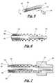
- FIG. 5is a perspective view of the inner liner having the single filament winding applied in a second pass from the distal end to the proximal end.
- FIG. 6is a cross section of the inner liner showing the second pass of the single filament winding.
- FIG. 7is a cross section of the catheter with two passes of the filament winding and a plastic coating applied over the filament winding.
- FIG. 8is a perspective view of a catheter having additional layers of filament winding applied over the initial layer and marker bands at the distal ends of each layer.
- FIG. 9is a cross section view of the catheter shown in FIG. 8 .
- FIG. 10shows the use of multiple bobbins to apply multiple strands of filament winding at the same time.
- FIG. 11shows the use of wire guides in conjunction with the multiple bobbins for varying the spacing between the filaments as the bobbins move along a length of the catheter.
- FIG. 12is a plan view of the process shown in FIG. 11 .
- FIG. 13is a cross section of a catheter having a bundle of filament wires wound about the inner lining with a closely packed filament spacing within the bundle and a variable pitch along the length of the catheter.
- FIG. 14is a perspective view of the bundle of filaments being applied to the catheter of FIG. 13 .
- FIG. 15is a perspective view of the catheter of FIGS. 13 and 14 with a wire guide assembly for guiding the bundle of filaments onto the catheter.
- FIG. 1shows a mandrel 11 on which the catheter 10 is formed.
- the catheter 10can be formed directly on the mandrel 11 , or on a core substrate 12 that forms an inner lining of the catheter 10 and is slid over the mandrel 11 as shown in FIG. 2 .
- the phrase “core member”will be used in this application to refer to either the mandrel 11 or the substrate 12 , whichever is used to form the core of the catheter 10 .
- FIG. 3shows the process of winding a single filament 13 around the core member 12 (i.e., the substrate).
- the filament 13is anchored at or near a proximal end 14 of the core member 12 before the winding starts.
- the core member 12is then rotated about its longitudinal axis by a suitable apparatus 15 .
- the filament 13is fed onto the rotating core member 12 from a filament source 16 , such as a filament spool or bobbin.
- the filament source 16is moved along a guide 17 in a direction generally parallel to the longitudinal axis of the core member 12 from a starting position near the proximal end 14 of the core member 12 toward the distal end 18 .
- the speed of rotation of the core member 12 and/or the speed of translation of the filament source 16can be varied to change the pitch (i.e., turning angle) of the filament winding 19 .
- the pitch of the winding 19can be changed so that the turns of the winding 19 are spaced differently near the proximal end 14 than near the distal end 18 .
- the pitchcan be changed to provide closely spaced turns of the filament 13
- the pitchcan be changed to provide loosely spaced turns.
- FIG. 3shows a process in which the core member 12 is rotated about its axis and the filament source 16 is moved parallel to the core member 12
- the core member 12can be held stationary while the filament source 16 orbits around the core member 12 and also moves along a length of the core member 12 to wind the filament 13 on the core member 12
- the filament source 16can be held stationary while the core member 12 rotates about its axis and also moves in an axial direction. It will be understood that each of these process variations and others can be used to accomplish the desired relative movement between the core member 12 and the filament source 16 .
- a first pass 20 of the filament winding 19 over the core member 12is completed as shown in FIG. 4 .
- the filament winding 19can have a variable pitch in which the turns of the winding 19 become closer together near the distal end 18 of the core member 12 .
- the filament winding 19can have a constant pitch in which the turns of the winding 19 are evenly spaced over the entire length of the core member 12 .
- a second pass 21 of the filament winding 19is then applied over the core member 12 (and over the first pass 20 of the filament winding 19 ) as the filament source 16 moves back toward the proximal end 14 .
- the filament winding 19is continuous from its initial anchor at the proximal end 14 , to the end of the first pass 20 at the distal end 18 of the core member 12 , and then back to the end of the second pass 21 at the proximal end 14 .
- the second pass 21 of the winding 19can be applied with a variable pitch similar to the first pass 20 .
- a plastic coating 23is applied over the first fibrous layer 22 as shown in FIG. 7 .
- the plastic coating 23can be formed by applying a polymer material in a particulate preform over an outer surface of the core member 12 and the fibrous layer 22 .
- a suitable process for applying the plastic coating in this manneris disclosed, for example, in the Applicant's U.S. Pat. No. 6,030,371, which is incorporated herein by reference.
- the plastic coating 23can be applied by laminating a plastic tube over an outer surface of the core member 12 and the fibrous layer 22 , or by extruding the plastic material over the fibrous layer 22 , or by using electrostatic forces to apply the plastic material as a molecular strand using a nanospinning process. After the plastic coating 23 is applied, the proximal end 14 of the catheter 10 is anchored in a suitable hub 24 .
- a catheter 30 having multiple fibrous reinforcement layers 31 , 32 , 33can be formed by repeating the process described above.
- the first fibrous layer 31 of the cathetercan be formed using the same process used to forming the first layer 22 in the above-described catheter 10 .
- the additional fibrous layers 32 , 33can be applied over the first fibrous layer 31 to impart different properties along a length of the catheter 30 .
- Each additional fibrous layer 32 , 33can be formed in a manner similar to the first layer 31 .
- the filament for the first additional layer 32is anchored in the proximal end, and then the filament is wound over the first fibrous layer 31 as the filament source is moved axially along the core member from the proximal end to a distal position and then back to the proximal end.
- the distal end 34 of the first additional layer 32can be an intermediate point along the catheter 30 between the proximal and distal ends, as shown in FIGS. 8 and 9 .
- the second additional layer 33can be formed in a similar manner to the first additional layer 32 .
- the distal end 35 of the second additional layer 33can be at another intermediate point along the catheter 30 .
- the additional layers 32 , 33can be progressively shorter than the first layer 31 so that the catheter 30 has a tapering profile and variable properties along its length.
- the pitch of the windings in each fibrous layer 31 - 33can be varied as shown in FIGS. 8 and 9 , or the pitch can be constant (not shown) so that the windings are spaced uniformly over a length of the catheter.
- a plastic coatingcan be applied over all of the fibrous layers 31 - 33 simultaneously, or the coating can be applied over each of the fibrous layers separately before the next fibrous layer is formed.
- each fibrous layer 31 - 33provides an ideal location to place marker bands 36 , 37 , 38 for the catheter 30 .
- the marker bands 36 - 38are typically formed of thin metal and can be selected to have approximately the same thickness as the corresponding fibrous layer 31 - 33 .
- the fibrous layers 31 - 33can each be formed using two passes of 0.0005 inch diameter filament, and the marker bands 36 - 38 can be formed using metal bands having a 0.001 inch thickness.
- a group of filaments 40are wound on the core member 41 simultaneously.
- the group of filaments 40can be supplied from a plurality of filament sources 42 - 45 (e.g., bobbins or spools).
- the filament sources 42 - 45are moved in a controlled manner relative to the core member 41 so that windings having either a constant or a variable pitch can be applied over a length of the core member 41 .
- the group of filaments 40can be wound with a variable pitch such that a filament group spacing at a distal end 46 of the core member 41 is narrower than a filament group spacing at a proximal end 47 of the core member 41 , as shown in detail in FIG. 13 .
- the filament sources 42 - 45can also be moved relative to each other to vary the spacing between the filaments within the group 40 as the winding progresses over a length of the catheter.
- the filament spacing between the filaments within the group 40 at a distal end 46 of the core member 41can be made narrower than the filament spacing at a proximal end 47 thereof.
- the group of filaments 40can be wound with a variable pitch and a variable spacing between the filaments within the filament group 40 .
- a plurality of wire guides 51 - 54can be used to control the filament spacing within a group of filaments 50 .
- the spacing between the wire guides 51 - 54can be varied as the winding proceeds along a length of the core member 55 to change the filament spacing within the filament group 50 .
- the use of wire guides 51 - 54eliminates the slight fluctuations in spacing that would otherwise occur if the filaments were simply fed off of a spool or bobbin and directly onto the core member 55 .
- FIGS. 13 to 15show an additional embodiment in which a group 60 of filaments 61 - 64 are wound onto the core member 65 in a close side-by-side arrangement.
- the closely packed group 60is formed using a guide assembly 66 , depicted in FIG. 15 , which has a filament engaging surface 67 that lies in a plane generally perpendicular to a longitudinal axis of the core member 65 .
- the guide assembly 66functions as the filament source.
- the filaments 61 - 64are arranged in a common plane which is approximately perpendicular to a plane containing the filaments 61 - 64 as they first engage an outer surface of the core member 65 .
- the filament engaging surface 67 of the guide assembly 66can extend along a vertical line.
- the guide assembly 66 arranged in this mannercauses the filaments 61 - 64 within the group 60 of filaments to be positioned side-by-side and packed tightly against one another as the group 60 of filaments are wound onto the core member 65 .
- the pitch of the group 60 of filaments being wound onto the core member 65can be varied by varying a rotation speed of the core member 65 and/or a translation speed of the guide assembly 66 as the filament source, in the manner described above.
- the guide assembly 66can be used to apply a group 60 of filament windings in two continuous passes to form a first fibrous layer over the outer surface of the core member 65 .
- all of the ends of the filaments 61 - 64can be anchored in the proximal end of the catheter, and the filaments 61 - 64 will be continuous at the distal end 68 of the catheter to avoid fraying and improving the performance of the catheter.
- the guide assembly and the other methods described herein for applying a group of filaments simultaneouslycan be used to form a fibrous layer in the catheter with a single pass over the core member and the distal ends of the filaments anchored at the distal end of the catheter.
- catheters having superior properties over the prior artcan be formed by the methods described above.
- the catheters in each embodimentwill have a proximal end, a distal end, a lumen extending between the proximal and distal ends, and at least one fibrous reinforcement layer in a wall of the catheter.
- the fibrous layer according to the preferred embodimentwill have a continuous filament with first and second ends and a series of windings formed between the first and second ends. The first and second ends of the filament are anchored in the proximal end of the catheter, and the windings extend over a length of the catheter from the proximal end to the distal end. It will be understood that the catheters formed by each of the methods described herein are also considered part of the present invention.
Landscapes
- Health & Medical Sciences (AREA)
- Life Sciences & Earth Sciences (AREA)
- Biophysics (AREA)
- Pulmonology (AREA)
- Engineering & Computer Science (AREA)
- Anesthesiology (AREA)
- Biomedical Technology (AREA)
- Heart & Thoracic Surgery (AREA)
- Hematology (AREA)
- Animal Behavior & Ethology (AREA)
- General Health & Medical Sciences (AREA)
- Public Health (AREA)
- Veterinary Medicine (AREA)
- Media Introduction/Drainage Providing Device (AREA)
Abstract
Description
Claims (7)
Priority Applications (1)
| Application Number | Priority Date | Filing Date | Title |
|---|---|---|---|
| US10/735,352US7445684B2 (en) | 2003-12-11 | 2003-12-11 | Catheter having fibrous reinforcement and method of making the same |
Applications Claiming Priority (1)
| Application Number | Priority Date | Filing Date | Title |
|---|---|---|---|
| US10/735,352US7445684B2 (en) | 2003-12-11 | 2003-12-11 | Catheter having fibrous reinforcement and method of making the same |
Publications (2)
| Publication Number | Publication Date |
|---|---|
| US20050131387A1 US20050131387A1 (en) | 2005-06-16 |
| US7445684B2true US7445684B2 (en) | 2008-11-04 |
Family
ID=34653597
Family Applications (1)
| Application Number | Title | Priority Date | Filing Date |
|---|---|---|---|
| US10/735,352Expired - Fee RelatedUS7445684B2 (en) | 2003-12-11 | 2003-12-11 | Catheter having fibrous reinforcement and method of making the same |
Country Status (1)
| Country | Link |
|---|---|
| US (1) | US7445684B2 (en) |
Cited By (15)
| Publication number | Priority date | Publication date | Assignee | Title |
|---|---|---|---|---|
| US7785439B2 (en) | 2004-09-29 | 2010-08-31 | Abbott Laboratories Vascular Enterprises Limited | Method for connecting a catheter balloon with a catheter shaft of a balloon catheter |
| US8323432B2 (en) | 2002-12-31 | 2012-12-04 | Abbott Laboratories Vascular Enterprises Limited | Catheter and method of manufacturing same |
| US8968383B1 (en) | 2013-08-27 | 2015-03-03 | Covidien Lp | Delivery of medical devices |
| US9108017B2 (en) | 2011-03-22 | 2015-08-18 | Applied Medical Resources Corporation | Method of making tubing have drainage holes |
| US9782186B2 (en) | 2013-08-27 | 2017-10-10 | Covidien Lp | Vascular intervention system |
| US10376396B2 (en) | 2017-01-19 | 2019-08-13 | Covidien Lp | Coupling units for medical device delivery systems |
| US10537452B2 (en) | 2012-02-23 | 2020-01-21 | Covidien Lp | Luminal stenting |
| US10786377B2 (en) | 2018-04-12 | 2020-09-29 | Covidien Lp | Medical device delivery |
| US11071637B2 (en) | 2018-04-12 | 2021-07-27 | Covidien Lp | Medical device delivery |
| US11123209B2 (en) | 2018-04-12 | 2021-09-21 | Covidien Lp | Medical device delivery |
| US11413176B2 (en) | 2018-04-12 | 2022-08-16 | Covidien Lp | Medical device delivery |
| US11413174B2 (en) | 2019-06-26 | 2022-08-16 | Covidien Lp | Core assembly for medical device delivery systems |
| US11944558B2 (en) | 2021-08-05 | 2024-04-02 | Covidien Lp | Medical device delivery devices, systems, and methods |
| US12042413B2 (en) | 2021-04-07 | 2024-07-23 | Covidien Lp | Delivery of medical devices |
| US12109137B2 (en) | 2021-07-30 | 2024-10-08 | Covidien Lp | Medical device delivery |
Families Citing this family (31)
| Publication number | Priority date | Publication date | Assignee | Title |
|---|---|---|---|---|
| US7316677B1 (en)* | 1999-04-30 | 2008-01-08 | Applied Medical Resources Corporation | Ureteral access sheath |
| US20050004515A1 (en)* | 2002-11-15 | 2005-01-06 | Hart Charles C. | Steerable kink resistant sheath |
| US8529719B2 (en) | 2002-11-15 | 2013-09-10 | Applied Medical Resources Corporation | Method of making medical tubing having variable characteristics using thermal winding |
| US7005026B2 (en)* | 2002-11-15 | 2006-02-28 | Applied Medical Resources Corporation | Kink-resistant access sheath and method of making same |
| US20050165366A1 (en) | 2004-01-28 | 2005-07-28 | Brustad John R. | Medical tubing having variable characteristics and method of making same |
| US7658723B2 (en)* | 2004-05-27 | 2010-02-09 | Abbott Laboratories | Catheter having plurality of stiffening members |
| US7785318B2 (en)* | 2004-05-27 | 2010-08-31 | Abbott Laboratories | Catheter having plurality of stiffening members |
| US7794448B2 (en)* | 2004-05-27 | 2010-09-14 | Abbott Laboratories | Multiple lumen catheter and method of making same |
| US7625353B2 (en)* | 2004-05-27 | 2009-12-01 | Abbott Laboratories | Catheter having first and second guidewire tubes and overlapping stiffening members |
| US7628769B2 (en)* | 2004-05-27 | 2009-12-08 | Abbott Laboratories | Catheter having overlapping stiffening members |
| US7815627B2 (en)* | 2004-05-27 | 2010-10-19 | Abbott Laboratories | Catheter having plurality of stiffening members |
| GB201020512D0 (en)* | 2010-12-03 | 2011-01-19 | Magma Global Ltd | Composite pipe |
| GB2490685B (en)* | 2011-05-10 | 2017-05-24 | Salunda Ltd | Fluid conduit |
| US10238406B2 (en) | 2013-10-21 | 2019-03-26 | Inari Medical, Inc. | Methods and apparatus for treating embolism |
| EP3164086B1 (en)* | 2014-07-01 | 2020-04-08 | Boston Scientific Scimed, Inc. | Overlapped braid termination |
| US10357631B2 (en)* | 2015-05-29 | 2019-07-23 | Covidien Lp | Catheter with tapering outer diameter |
| EP3302669B1 (en)* | 2015-05-29 | 2020-10-07 | Covidien LP | Catheter with tapering outer diameter |
| CN113796927B (en) | 2015-10-23 | 2025-03-04 | 伊纳里医疗公司 | Intravascular treatment of vascular occlusion and related devices, systems and methods |
| US11721476B1 (en)* | 2015-11-05 | 2023-08-08 | St Jude Medical International Holding S.À R.L. | Sensor coil assembly |
| US10118334B2 (en)* | 2016-07-14 | 2018-11-06 | Custom Wire Technologies, Inc. | Wire-reinforced tubing and method of making the same |
| FI3528717T3 (en) | 2016-10-24 | 2024-08-09 | Inari Medical Inc | Devices for treating vascular occlusion |
| EP3593848B1 (en)* | 2017-03-10 | 2022-04-20 | Asahi Intecc Co., Ltd. | Catheter |
| WO2019050765A1 (en) | 2017-09-06 | 2019-03-14 | Inari Medical, Inc. | Hemostasis valves and methods of use |
| US10773051B2 (en) | 2018-01-24 | 2020-09-15 | Covidien Lp | Methods of manufacturing a catheter having a sensor |
| US11154314B2 (en) | 2018-01-26 | 2021-10-26 | Inari Medical, Inc. | Single insertion delivery system for treating embolism and associated systems and methods |
| CA3114285A1 (en) | 2018-08-13 | 2020-02-20 | Inari Medical, Inc. | System for treating embolism and associated devices and methods |
| JP7638273B2 (en) | 2019-10-16 | 2025-03-03 | イナリ メディカル, インコーポレイテッド | Systems, devices and methods for treating vascular obstructions |
| EP4463083A1 (en) | 2022-01-11 | 2024-11-20 | Inari Medical, Inc. | Devices for removing clot material from intravascularly implanted devices, and associated systems and methods |
| CN116650794A (en)* | 2022-02-21 | 2023-08-29 | 微创神通医疗科技(上海)有限公司 | catheter |
| EP4583954A2 (en)* | 2022-09-09 | 2025-07-16 | Inari Medical, Inc. | Catheters having multiple coil layers, and associated systems and methods |
| WO2025054176A1 (en)* | 2023-09-08 | 2025-03-13 | Merit Medical Systems, Inc. | Systems and methods of forming a continuous reinforced catheter shaft |
Citations (10)
| Publication number | Priority date | Publication date | Assignee | Title |
|---|---|---|---|---|
| US3701489A (en)* | 1968-03-01 | 1972-10-31 | William D Goldsworthy | Apparatus for winding filament about three axes of a mandrel |
| US4484586A (en)* | 1982-05-27 | 1984-11-27 | Berkley & Company, Inc. | Hollow conductive medical tubing |
| US4878984A (en)* | 1985-05-28 | 1989-11-07 | Manufacture D'appareillage Electrique De Cahors | Apparatus for forming a filament-wound structure on a cylindrical pole |
| US4952312A (en)* | 1988-11-24 | 1990-08-28 | Sorin Biomedica S.P.A. | Method for winding the fibres of exchange devices, such as blood oxygenators and the like, and an exchange device produced by this method |
| US5888436A (en)* | 1994-10-28 | 1999-03-30 | Hv Technologies, Inc. | Manufacture of variable stiffness microtubing |
| US6030371A (en)* | 1996-08-23 | 2000-02-29 | Pursley; Matt D. | Catheters and method for nonextrusion manufacturing of catheters |
| US6152912A (en)* | 1997-06-10 | 2000-11-28 | Target Therapeutics, Inc. | Optimized high performance spiral-wound vascular catheter |
| US20010041881A1 (en)* | 1999-07-28 | 2001-11-15 | Scimed Life Systems, Inc. | Catheter having continuous lattice and coil reinforcement |
| US20010044633A1 (en)* | 2000-01-28 | 2001-11-22 | Klint Henrik Sonderskov | Endovascular medical device with plurality of wires |
| US6511462B1 (en)* | 1999-07-16 | 2003-01-28 | Terumo Kabushiki Kaisha | Catheter and method of manufacturing the same |
- 2003
- 2003-12-11USUS10/735,352patent/US7445684B2/ennot_activeExpired - Fee Related
Patent Citations (10)
| Publication number | Priority date | Publication date | Assignee | Title |
|---|---|---|---|---|
| US3701489A (en)* | 1968-03-01 | 1972-10-31 | William D Goldsworthy | Apparatus for winding filament about three axes of a mandrel |
| US4484586A (en)* | 1982-05-27 | 1984-11-27 | Berkley & Company, Inc. | Hollow conductive medical tubing |
| US4878984A (en)* | 1985-05-28 | 1989-11-07 | Manufacture D'appareillage Electrique De Cahors | Apparatus for forming a filament-wound structure on a cylindrical pole |
| US4952312A (en)* | 1988-11-24 | 1990-08-28 | Sorin Biomedica S.P.A. | Method for winding the fibres of exchange devices, such as blood oxygenators and the like, and an exchange device produced by this method |
| US5888436A (en)* | 1994-10-28 | 1999-03-30 | Hv Technologies, Inc. | Manufacture of variable stiffness microtubing |
| US6030371A (en)* | 1996-08-23 | 2000-02-29 | Pursley; Matt D. | Catheters and method for nonextrusion manufacturing of catheters |
| US6152912A (en)* | 1997-06-10 | 2000-11-28 | Target Therapeutics, Inc. | Optimized high performance spiral-wound vascular catheter |
| US6511462B1 (en)* | 1999-07-16 | 2003-01-28 | Terumo Kabushiki Kaisha | Catheter and method of manufacturing the same |
| US20010041881A1 (en)* | 1999-07-28 | 2001-11-15 | Scimed Life Systems, Inc. | Catheter having continuous lattice and coil reinforcement |
| US20010044633A1 (en)* | 2000-01-28 | 2001-11-22 | Klint Henrik Sonderskov | Endovascular medical device with plurality of wires |
Cited By (29)
| Publication number | Priority date | Publication date | Assignee | Title |
|---|---|---|---|---|
| US8323432B2 (en) | 2002-12-31 | 2012-12-04 | Abbott Laboratories Vascular Enterprises Limited | Catheter and method of manufacturing same |
| US8092634B2 (en) | 2004-09-29 | 2012-01-10 | Abbott Laboratories Vascular Enterprises Limited | Method for connecting a catheter balloon with a catheter shaft of a balloon catheter |
| US7785439B2 (en) | 2004-09-29 | 2010-08-31 | Abbott Laboratories Vascular Enterprises Limited | Method for connecting a catheter balloon with a catheter shaft of a balloon catheter |
| US9108017B2 (en) | 2011-03-22 | 2015-08-18 | Applied Medical Resources Corporation | Method of making tubing have drainage holes |
| US11259946B2 (en) | 2012-02-23 | 2022-03-01 | Covidien Lp | Luminal stenting |
| US10537452B2 (en) | 2012-02-23 | 2020-01-21 | Covidien Lp | Luminal stenting |
| US10265207B2 (en) | 2013-08-27 | 2019-04-23 | Covidien Lp | Delivery of medical devices |
| US10695204B2 (en) | 2013-08-27 | 2020-06-30 | Covidien Lp | Delivery of medical devices |
| US10045867B2 (en) | 2013-08-27 | 2018-08-14 | Covidien Lp | Delivery of medical devices |
| US10092431B2 (en) | 2013-08-27 | 2018-10-09 | Covidien Lp | Delivery of medical devices |
| US9782186B2 (en) | 2013-08-27 | 2017-10-10 | Covidien Lp | Vascular intervention system |
| US11103374B2 (en) | 2013-08-27 | 2021-08-31 | Covidien Lp | Delivery of medical devices |
| US9775733B2 (en) | 2013-08-27 | 2017-10-03 | Covidien Lp | Delivery of medical devices |
| US9827126B2 (en) | 2013-08-27 | 2017-11-28 | Covidien Lp | Delivery of medical devices |
| US8968383B1 (en) | 2013-08-27 | 2015-03-03 | Covidien Lp | Delivery of medical devices |
| US11076972B2 (en) | 2013-08-27 | 2021-08-03 | Covidien Lp | Delivery of medical devices |
| US12343273B2 (en) | 2013-08-27 | 2025-07-01 | Covidien Lp | Delivery of medical devices |
| US10945867B2 (en) | 2017-01-19 | 2021-03-16 | Covidien Lp | Coupling units for medical device delivery systems |
| US10376396B2 (en) | 2017-01-19 | 2019-08-13 | Covidien Lp | Coupling units for medical device delivery systems |
| US11833069B2 (en) | 2017-01-19 | 2023-12-05 | Covidien Lp | Coupling units for medical device delivery systems |
| US10786377B2 (en) | 2018-04-12 | 2020-09-29 | Covidien Lp | Medical device delivery |
| US11413176B2 (en) | 2018-04-12 | 2022-08-16 | Covidien Lp | Medical device delivery |
| US11648140B2 (en) | 2018-04-12 | 2023-05-16 | Covidien Lp | Medical device delivery |
| US11123209B2 (en) | 2018-04-12 | 2021-09-21 | Covidien Lp | Medical device delivery |
| US11071637B2 (en) | 2018-04-12 | 2021-07-27 | Covidien Lp | Medical device delivery |
| US11413174B2 (en) | 2019-06-26 | 2022-08-16 | Covidien Lp | Core assembly for medical device delivery systems |
| US12042413B2 (en) | 2021-04-07 | 2024-07-23 | Covidien Lp | Delivery of medical devices |
| US12109137B2 (en) | 2021-07-30 | 2024-10-08 | Covidien Lp | Medical device delivery |
| US11944558B2 (en) | 2021-08-05 | 2024-04-02 | Covidien Lp | Medical device delivery devices, systems, and methods |
Also Published As
| Publication number | Publication date |
|---|---|
| US20050131387A1 (en) | 2005-06-16 |
Similar Documents
| Publication | Publication Date | Title |
|---|---|---|
| US7445684B2 (en) | Catheter having fibrous reinforcement and method of making the same | |
| US4534163A (en) | Rope or cable and method of making same | |
| US4870887A (en) | Braided sleeve | |
| US4516972A (en) | Guiding catheter and method of manufacture | |
| US12064565B2 (en) | Filament wrapping and reflow system and methods to manufacture an elongate medical device | |
| JPH0238271A (en) | Manufacture of bound body without spool, bound body manufactured through said method, device for executing said method and device for winding and unbinding bound body | |
| JP2010018443A (en) | Optical fiber spool and method for winding optical fiber around optical fiber spool | |
| HU179313B (en) | Method and apparatus for sz-twisting by layers of kink elements on flexible core | |
| US4309865A (en) | Method and apparatus for producing windings of fiber compound material on a core | |
| US20070125487A1 (en) | Method and apparatus for maintaining filaments in position in a filament winding process | |
| CA1290995C (en) | Apparatus and process of manufacturing a metal cord | |
| GB1573331A (en) | Methods of and apparatuses for producing multiple core power current cables or conductors | |
| KR950008366B1 (en) | Manufacturing method and apparatus for steel cord | |
| JPS6351773B2 (en) | ||
| US4925125A (en) | Deep nested filament winding | |
| JPH04303618A (en) | Manufacture of heat-shrinkable plastic hose with heat-shrinkable yarn and plastic hose thereof | |
| EP0336052B1 (en) | Assembly for winding filaments or threadlike material to a longish mandrel | |
| EP0436505B1 (en) | Deep nested filament winding | |
| CA1146026A (en) | Stranding stock of large cross sections | |
| CA1083393A (en) | Load bearing optical fiber cables | |
| US5154366A (en) | High density filament winding and method for producing improved crossovers and inside payout | |
| US4961545A (en) | Deep nested filament winding | |
| JPH0248475Y2 (en) | ||
| JP2018180329A (en) | Method of manufacturing optical fiber cable and manufacturing apparatus of optical fiber cable | |
| AU617564B2 (en) | High density filament winding and method for producing improved crossovers and inside payout |
Legal Events
| Date | Code | Title | Description |
|---|---|---|---|
| STCF | Information on status: patent grant | Free format text:PATENTED CASE | |
| AS | Assignment | Owner name:IMPACT MEDICAL TECHNOLOGIES, LLC, GEORGIA Free format text:ASSIGNMENT OF ASSIGNORS INTEREST;ASSIGNOR:PURSLEY, MATT D.;REEL/FRAME:021861/0049 Effective date:20081105 | |
| AS | Assignment | Owner name:VOLCANO CORPORATION,CALIFORNIA Free format text:ASSIGNMENT OF ASSIGNORS INTEREST;ASSIGNOR:IMPACT MEDICAL TECHNOLOGIES LLC;REEL/FRAME:024023/0106 Effective date:20081110 Owner name:VOLCANO CORPORATION, CALIFORNIA Free format text:ASSIGNMENT OF ASSIGNORS INTEREST;ASSIGNOR:IMPACT MEDICAL TECHNOLOGIES LLC;REEL/FRAME:024023/0106 Effective date:20081110 | |
| FPAY | Fee payment | Year of fee payment:4 | |
| FPAY | Fee payment | Year of fee payment:8 | |
| FEPP | Fee payment procedure | Free format text:MAINTENANCE FEE REMINDER MAILED (ORIGINAL EVENT CODE: REM.); ENTITY STATUS OF PATENT OWNER: SMALL ENTITY | |
| LAPS | Lapse for failure to pay maintenance fees | Free format text:PATENT EXPIRED FOR FAILURE TO PAY MAINTENANCE FEES (ORIGINAL EVENT CODE: EXP.); ENTITY STATUS OF PATENT OWNER: SMALL ENTITY | |
| STCH | Information on status: patent discontinuation | Free format text:PATENT EXPIRED DUE TO NONPAYMENT OF MAINTENANCE FEES UNDER 37 CFR 1.362 | |
| FP | Lapsed due to failure to pay maintenance fee | Effective date:20201104 |