US7444838B2 - Holey optical fiber with random pattern of holes and method for making same - Google Patents
Holey optical fiber with random pattern of holes and method for making sameDownload PDFInfo
- Publication number
- US7444838B2 US7444838B2US10/863,805US86380504AUS7444838B2US 7444838 B2US7444838 B2US 7444838B2US 86380504 AUS86380504 AUS 86380504AUS 7444838 B2US7444838 B2US 7444838B2
- Authority
- US
- United States
- Prior art keywords
- fiber
- holes
- gas
- generating material
- gas generating
- Prior art date
- Legal status (The legal status is an assumption and is not a legal conclusion. Google has not performed a legal analysis and makes no representation as to the accuracy of the status listed.)
- Expired - Lifetime, expires
Links
Images

Classifications
- G—PHYSICS
- G02—OPTICS
- G02B—OPTICAL ELEMENTS, SYSTEMS OR APPARATUS
- G02B6/00—Light guides; Structural details of arrangements comprising light guides and other optical elements, e.g. couplings
- G02B6/02—Optical fibres with cladding with or without a coating
- G02B6/02295—Microstructured optical fibre
- G02B6/02314—Plurality of longitudinal structures extending along optical fibre axis, e.g. holes
- G02B6/02385—Comprising liquid, e.g. fluid filled holes
- C—CHEMISTRY; METALLURGY
- C03—GLASS; MINERAL OR SLAG WOOL
- C03B—MANUFACTURE, SHAPING, OR SUPPLEMENTARY PROCESSES
- C03B37/00—Manufacture or treatment of flakes, fibres, or filaments from softened glass, minerals, or slags
- C03B37/01—Manufacture of glass fibres or filaments
- C03B37/012—Manufacture of preforms for drawing fibres or filaments
- C03B37/0128—Manufacture of preforms for drawing fibres or filaments starting from pulverulent glass
- C03B37/01291—Manufacture of preforms for drawing fibres or filaments starting from pulverulent glass by progressive melting, e.g. melting glass powder during delivery to and adhering the so-formed melt to a target or preform, e.g. the Plasma Oxidation Deposition [POD] process
- C03B37/01297—Manufacture of preforms for drawing fibres or filaments starting from pulverulent glass by progressive melting, e.g. melting glass powder during delivery to and adhering the so-formed melt to a target or preform, e.g. the Plasma Oxidation Deposition [POD] process by melting glass powder in a mould
- C—CHEMISTRY; METALLURGY
- C03—GLASS; MINERAL OR SLAG WOOL
- C03B—MANUFACTURE, SHAPING, OR SUPPLEMENTARY PROCESSES
- C03B37/00—Manufacture or treatment of flakes, fibres, or filaments from softened glass, minerals, or slags
- C03B37/01—Manufacture of glass fibres or filaments
- C03B37/012—Manufacture of preforms for drawing fibres or filaments
- C03B37/014—Manufacture of preforms for drawing fibres or filaments made entirely or partially by chemical means, e.g. vapour phase deposition of bulk porous glass either by outside vapour deposition [OVD], or by outside vapour phase oxidation [OVPO] or by vapour axial deposition [VAD]
- C03B37/016—Manufacture of preforms for drawing fibres or filaments made entirely or partially by chemical means, e.g. vapour phase deposition of bulk porous glass either by outside vapour deposition [OVD], or by outside vapour phase oxidation [OVPO] or by vapour axial deposition [VAD] by a liquid phase reaction process, e.g. through a gel phase
- C—CHEMISTRY; METALLURGY
- C03—GLASS; MINERAL OR SLAG WOOL
- C03B—MANUFACTURE, SHAPING, OR SUPPLEMENTARY PROCESSES
- C03B37/00—Manufacture or treatment of flakes, fibres, or filaments from softened glass, minerals, or slags
- C03B37/01—Manufacture of glass fibres or filaments
- C03B37/02—Manufacture of glass fibres or filaments by drawing or extruding, e.g. direct drawing of molten glass from nozzles; Cooling fins therefor
- C03B37/025—Manufacture of glass fibres or filaments by drawing or extruding, e.g. direct drawing of molten glass from nozzles; Cooling fins therefor from reheated softened tubes, rods, fibres or filaments, e.g. drawing fibres from preforms
- C03B37/027—Fibres composed of different sorts of glass, e.g. glass optical fibres
- C03B37/02781—Hollow fibres, e.g. holey fibres
- C—CHEMISTRY; METALLURGY
- C03—GLASS; MINERAL OR SLAG WOOL
- C03C—CHEMICAL COMPOSITION OF GLASSES, GLAZES OR VITREOUS ENAMELS; SURFACE TREATMENT OF GLASS; SURFACE TREATMENT OF FIBRES OR FILAMENTS MADE FROM GLASS, MINERALS OR SLAGS; JOINING GLASS TO GLASS OR OTHER MATERIALS
- C03C11/00—Multi-cellular glass ; Porous or hollow glass or glass particles
- C03C11/007—Foam glass, e.g. obtained by incorporating a blowing agent and heating
- C—CHEMISTRY; METALLURGY
- C03—GLASS; MINERAL OR SLAG WOOL
- C03C—CHEMICAL COMPOSITION OF GLASSES, GLAZES OR VITREOUS ENAMELS; SURFACE TREATMENT OF GLASS; SURFACE TREATMENT OF FIBRES OR FILAMENTS MADE FROM GLASS, MINERALS OR SLAGS; JOINING GLASS TO GLASS OR OTHER MATERIALS
- C03C13/00—Fibre or filament compositions
- C03C13/04—Fibre optics, e.g. core and clad fibre compositions
- G—PHYSICS
- G01—MEASURING; TESTING
- G01L—MEASURING FORCE, STRESS, TORQUE, WORK, MECHANICAL POWER, MECHANICAL EFFICIENCY, OR FLUID PRESSURE
- G01L1/00—Measuring force or stress, in general
- G01L1/24—Measuring force or stress, in general by measuring variations of optical properties of material when it is stressed, e.g. by photoelastic stress analysis using infrared, visible light, ultraviolet
- G01L1/242—Measuring force or stress, in general by measuring variations of optical properties of material when it is stressed, e.g. by photoelastic stress analysis using infrared, visible light, ultraviolet the material being an optical fibre
- G01L1/243—Measuring force or stress, in general by measuring variations of optical properties of material when it is stressed, e.g. by photoelastic stress analysis using infrared, visible light, ultraviolet the material being an optical fibre using means for applying force perpendicular to the fibre axis
- G—PHYSICS
- G02—OPTICS
- G02B—OPTICAL ELEMENTS, SYSTEMS OR APPARATUS
- G02B6/00—Light guides; Structural details of arrangements comprising light guides and other optical elements, e.g. couplings
- G02B6/02—Optical fibres with cladding with or without a coating
- G02B6/02295—Microstructured optical fibre
- G02B6/02314—Plurality of longitudinal structures extending along optical fibre axis, e.g. holes
- G02B6/02319—Plurality of longitudinal structures extending along optical fibre axis, e.g. holes characterised by core or core-cladding interface features
- G02B6/02333—Core having higher refractive index than cladding, e.g. solid core, effective index guiding
- G—PHYSICS
- G02—OPTICS
- G02B—OPTICAL ELEMENTS, SYSTEMS OR APPARATUS
- G02B6/00—Light guides; Structural details of arrangements comprising light guides and other optical elements, e.g. couplings
- G02B6/02—Optical fibres with cladding with or without a coating
- G02B6/02295—Microstructured optical fibre
- G02B6/02314—Plurality of longitudinal structures extending along optical fibre axis, e.g. holes
- G02B6/02319—Plurality of longitudinal structures extending along optical fibre axis, e.g. holes characterised by core or core-cladding interface features
- G02B6/02338—Structured core, e.g. core contains more than one material, non-constant refractive index distribution in core, asymmetric or non-circular elements in core unit, multiple cores, insertions between core and clad
- G—PHYSICS
- G02—OPTICS
- G02B—OPTICAL ELEMENTS, SYSTEMS OR APPARATUS
- G02B6/00—Light guides; Structural details of arrangements comprising light guides and other optical elements, e.g. couplings
- G02B6/02—Optical fibres with cladding with or without a coating
- G02B6/02295—Microstructured optical fibre
- G02B6/02314—Plurality of longitudinal structures extending along optical fibre axis, e.g. holes
- G02B6/02342—Plurality of longitudinal structures extending along optical fibre axis, e.g. holes characterised by cladding features, i.e. light confining region
- G02B6/02357—Property of longitudinal structures or background material varies radially and/or azimuthally in the cladding, e.g. size, spacing, periodicity, shape, refractive index, graded index, quasiperiodic, quasicrystals
- G—PHYSICS
- G02—OPTICS
- G02B—OPTICAL ELEMENTS, SYSTEMS OR APPARATUS
- G02B6/00—Light guides; Structural details of arrangements comprising light guides and other optical elements, e.g. couplings
- G02B6/02—Optical fibres with cladding with or without a coating
- G02B6/02295—Microstructured optical fibre
- G02B6/02314—Plurality of longitudinal structures extending along optical fibre axis, e.g. holes
- G02B6/02342—Plurality of longitudinal structures extending along optical fibre axis, e.g. holes characterised by cladding features, i.e. light confining region
- G02B6/02366—Single ring of structures, e.g. "air clad"
- G—PHYSICS
- G02—OPTICS
- G02B—OPTICAL ELEMENTS, SYSTEMS OR APPARATUS
- G02B6/00—Light guides; Structural details of arrangements comprising light guides and other optical elements, e.g. couplings
- G02B6/02—Optical fibres with cladding with or without a coating
- G02B6/032—Optical fibres with cladding with or without a coating with non solid core or cladding
- C—CHEMISTRY; METALLURGY
- C03—GLASS; MINERAL OR SLAG WOOL
- C03B—MANUFACTURE, SHAPING, OR SUPPLEMENTARY PROCESSES
- C03B2203/00—Fibre product details, e.g. structure, shape
- C03B2203/10—Internal structure or shape details
- C03B2203/14—Non-solid, i.e. hollow products, e.g. hollow clad or with core-clad interface
- C—CHEMISTRY; METALLURGY
- C03—GLASS; MINERAL OR SLAG WOOL
- C03B—MANUFACTURE, SHAPING, OR SUPPLEMENTARY PROCESSES
- C03B2203/00—Fibre product details, e.g. structure, shape
- C03B2203/42—Photonic crystal fibres, e.g. fibres using the photonic bandgap PBG effect, microstructured or holey optical fibres
Definitions
- the present inventionwas developed, at least in part, with funding from the Air Force Office of Scientific Research, grant no. F49620-01-1-0191. Accordingly, the U.S. Government may have certain rights to this invention.
- the present inventionrelates generally to holey optical fibers and methods for making holey optical fibers. More specifically, the present invention relates to a new technique for making holey optical fibers having random patterns of holes. In the present method, a gas-generating material included in the fiber preform forms the holes as the fiber is drawn.
- Holey optical fibershave microscopic holes or voids for guiding light.
- the coreis solid (e.g. SiO2) and is surrounded by an array of holes containing inert gas or air.
- the light guided in the optical fibermay be confined to the central core region by one of two basic mechanisms.
- the first mechanismlight is confined to the central core region by a refractive index difference between the core and cladding material.
- the refractive index differenceis produced by dopants in either the core or cladding material in order to raise or lower the refractive indices of these regions.
- the index of the cladding regioncan also be lowered by introducing porosity in that region.
- the microscopic holeshave a much lower refractive index compared to the solid core, so light is confined to the core.
- the size and spacing of the holesis controlled in a very uniform and well defined pattern such that a photonic band gap is produced.
- the holesmust be periodically spaced and carefully arranged and maintained in the fiber to achieve the photonic band gap effects. These fibers are often referred to as photonic crystal fibers owing to their period arrangement of air holes in the fiber.
- the microscopic holesprovide unusual optical properties such as single-mode operation over a wide wavelength range, low zero-dispersion wavelength, and highly controllable birefringence. As a result, holey optical fibers are expected to have a wide range of applications in optical sensors and telecommunications.
- Holey optical fibersare conventionally manufactured by stacking an array of hollow silica tubes to form a preform.
- the tubesare carefully arranged to control the spacing between them and to ensure the crystalline arrangement.
- the preformis then heated and drawn into fibers as known in the art.
- the tubesgenerally experience a uniform scale reduction during drawing so that the tubes create the microscopic holes in the fiber.
- the present inventionincludes an optical fiber having a holey region with a random array of holes.
- the holesare created by gas generated during fiber drawing.
- the holey regioncan be disposed around a fiber core, so that the holey region functions as a cladding.
- the gascan be generated by nitride or carbide compounds. Silicon nitride and silicon carbide are exemplary gas generating materials. Carbides will typically produce carbon monoxide or carbon dioxide gas by decomposition and oxidation of carbon.
- the holesmay be filled with the gas generated during fiber drawing.
- the gasmay be nitrogen, carbon monoxide, carbon dioxide or mixed nitrogen oxides, for example.
- the random holescan have a uniform or nonuniform hole distribution.
- the present inventionincludes a method for making the present random hole optical fiber.
- a preformcontains the gas generating material that produces gas bubbles when heated.
- the preformis heated and drawn so that the gas bubbles are drawn into long holes.
- the preformmay comprise a glass powder mixed with the gas generating material.
- the gas generating materialmay be provided in the form of a liquid precursor.
- the liquid precursormay convert to a nitride or carbide material when heated.
- Oxygenmay be provided to the interior of the fiber preform so that the gas generating material is exposed to oxygen as it is heated.
- the present inventionincludes a pressure sensor or force sensor having the present random hole optical fiber.
- the present random hole optical fiberexhibits increased optical loss when in response to applied pressure or force.
- the random hole fibercan be used as a pressure or force sensor by monitoring optical loss in the fiber.
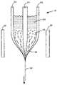
- FIG. 1illustrates the present method for making random hole optical fiber.
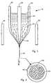
- FIG. 2shows a cross-sectional view of a random hole optical fiber.
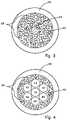
- FIG. 3shows a cross-sectional view of a fiber having random holes in the core.
- FIG. 4shows a cross sectional view of a fiber having random holes in combination with holes made from stacked tubes.
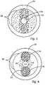
- FIG. 5shows a cross sectional view of a fiber having a non-uniform distribution of random holes.
- FIG. 6shows a cross sectional view of a fiber having a non-uniform distribution of random holes in which the random holes are confined by hollow tubes.
- FIG. 7shows a pressure sensor according to the present invention.
- FIG. 8shows plots of loss versus wavelength when 500 gram and 300 gram weights are rested on a random hole fiber.
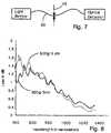
- FIG. 9shows plots of loss versus wavelength when 4000, 2000, and 800 gram weights are rested on a random hole fiber.
- the present inventionprovides a holey optical fiber with a random array of holes.
- the holey optical fiberis made by including a gas-generating material in the fiber preform.
- the gas generating materialis located around a solid core (e.g., made of solid SiO2).
- the gas generating materialmay be a nitride ceramic (e.g., silicon nitride, rare earth nitrides, AlN, TiN) or carbide ceramic (e.g. silicon carbide, rare earth carbides) that decomposes at or close to the fiber drawing temperature (e.g., 1500-1600 Celsius in the case of pure fused silica fibers).
- Decompositionproduces gas bubbles (e.g., N 2 , CO 2 , carbon monoxide or nitrogen oxides) in the molten preform material as it is drawn.
- the gas bubblesare randomly distributed and are drawn into long thin holes (or tubes) that remain in the optical fiber.
- the holesreduce the refractive index in the region surrounding the solid core, and so provide light confinement.
- the number and size of the holescan be influenced by the preform composition, drawing temperature, parent material particle size and drawing speed, among other factors. Though the holes have random locations, they can have nonuniform distribution by nonuniformly distributing the gas generating material.
- FIG. 1illustrates the present method for making random-hole optical fiber.
- a fiber preform 18comprises a silica tube 20 filled with a holey region forming powder 22 and a solid silica rod 24 .
- the holey region forming powder 22forms a fiber cladding and the solid rod 24 forms a fiber core.
- Heaters 26heat the preform 18 so that it can be pulled to form a fiber 28 , as known in the art.
- the holey region forming powder 22comprises a mixture of a glass material (e.g., high purity silica powder) and a gas-generating material (e.g., silicon nitride).
- the gas generating materialproduces a gas when heated above the sintering temperature of the glass material.
- the gas generating materialcan produce gas by thermal decomposition or by chemical reactions (e.g. oxidation) with other components of the holey region forming powder, for example.
- the gas generated within the holey region forming powder 22forms trapped bubbles 30 as the holey region forming powder 22 sinters and softens.
- the bubbles 30are stretched and drawn into elongated tubes 32 as the fiber 28 is pulled.
- the glass materialis silica
- the gas generating materialis a nitride or carbide ceramic.
- FIG. 2shows a magnified, cross sectional view of the present random hole optical fiber.
- the fiberhas a core 34 formed from the solid rod 24 , and a solid covering 36 formed from the tube 20 .
- a holey region 38provides a cladding around the core 34 .
- the holey regionis formed from the holey region forming powder 22 and contains a large number (e.g., >50 or >200) of holes 40 .
- the holes 40are created from the bubbles 30 .
- the holes 40are preferably long tubes that may be centimeters, meters, or kilometers long, for example, depending upon the size of the starting bubble in the preform and the additional gas generated (if any) during the drawing of the bubble into the tube.
- the holeswill typically have finely tapered ends, such that the diameter of the tube will reduce in size gradually as it reaches the end.
- the holesmay have typical diameters of 0.01-5 microns, for example, and may be even smaller at the ends.
- the holescan be as large as tens of microns.
- the holestypically lack continuity, but new ones form as old ones end so that the holey region 38 has a relatively constant porosity.
- the holes 40are filled with gas and so tend to reduce the average refractive index of the cladding region 38 .
- optical energywill be confined within the core 34 as known in the art.
- the holes 40are smaller than a wavelength of light in the fiber core, so that optical energy is minimally perturbed by individual bubbles 40 .
- Very small holes(e.g., less than 100 nm in diameter) may be required in applications where perturbation of the optical energy is undesirable.
- the holey region forming powder 20comprises mostly glass material (e.g., high purity silica powder) with a portion of a gas generating material.
- the gas generating materialis preferably a ceramic (e.g., nitride or carbide) that generates gas at or close to the temperature required for fiber drawing.
- the gas generating materialcan generate gas at temperatures in the range of about 1000-1600 C for silica fibers.
- the gas generating materialshould generate gas at temperatures above the sintering temperature of the holey region forming powder so that generated gas is trapped and cannot escape.
- the gascan be generated by decomposition and/or oxidation, for example.
- the gas that forms the bubbles 30can be any gas, but is preferably a relatively inert gas that does not interfere with desired light transmission properties of the optical fiber.
- the gas generating materialis silicon nitride.
- the silicon nitridecan be a powder mixed into the holey region forming powder 22 .
- the silicon nitridecan be a coating on the particles of glass material.
- Silicon nitrideis a preferred material for generating the gas bubbles 30 because it produces a relatively large amount of gas at the drawing temperature, and because it oxidizes to SiO2 (a preferred fiber material) during drawing. Silicon nitride is a preferred gas generating material when silica is the glass material.
- Silicon nitridecan be present in amounts less than about 1% by weight of the holey region forming powder when the balance is silica.
- silicon nitridecomprises about 0.01-0.5%, or, more typically, 0.04-0.1% of the holey region forming powder by weight, with the balance of the holey region forming powder being high purity silica.
- the amount of silicon nitridewill influence the porosity of the holey region. Larger amounts of silicon nitride will tend to produce higher porosity, and hence, a relatively lower average refractive index in the holey regions.
- the porosity of the holey regioncan vary widely.
- the present inventioncan produce porosities from less than 1% to 95% and higher.
- Low porositiescan be used in the cladding region of index-guiding fiber.
- High porositiescan be used to reduce optical loss from Rayleigh scattering, for example.
- silicon nitrideproduces gas by oxidation during drawing.
- Oxygen present in the holey region forming powderoxidizes the silicon nitride, producing SiO 2 , and nitrogen or nitrogen oxides or some mixture thereof.
- Oxygenmight also oxidize the nitrogen to form mixed nitrogen oxides.
- the oxygenmay be adsorbed on the surfaces of holey region forming powder particles, may be trapped in voids during sintering, or may be dissolved in the silica. Oxygen bound to silica may also contribute to the oxidation.
- the nitrogen and nitrogen oxide gasesmay remain in the holes of the final, drawn fiber.
- oxygen or other gasesmay be incorporated into the holey region forming powder during drawing.
- gasese.g., inert gases
- flowing oxygen gas into the holey region forming powdermay increase the oxidation of the silicon nitride and gas generation.
- the fiber preformcan also be filled with ambient air.
- Solid oxygen sourcese.g., nitrates
- the holey region forming powdercan have a wide range of particle sizes. Typical fibers made by the present inventors have employed 325 mesh and 100 mesh silica powder and sub-micron diameter silicon nitride powder. Other particle sizes can also be used and may influence the size of the holes 40 or porosity of the holey region. The size of the powder particles can affect the sintering temperature and amount of gas generated. If mixtures of powders are used, they should be thoroughly mixed before drawing, unless non-uniform hole distributions are desired.
- pre-oxidation of the gas generating material, drawing speed, pulling force and drawing temperaturemay also influence the porosity of the holey regions or the size of the holes.
- the glass material of the holey region forming powderis preferably high purity silica.
- other glassy materialscan be used instead.
- fluoride-containing glasses, borosilicate glasses, or other optical glassescan be used instead of silica. These other glasses may require different drawing conditions (e.g. different temperatures, absence of oxygen) and so may require use with specific gas generating materials.
- Silicon carbidecan also be used as the gas generating material. Silicon carbide tends to oxidize in the presence of oxygen at high temperature, forming SiO 2 and carbon monoxide or carbon dioxide. The carbon monoxide or carbon dioxide provides the bubbles 30 .
- the oxygen sourcecan be elemental oxygen present in the preform. Pure gaseous oxygen can be flowed into the preform to increase the amount of available oxygen.
- silicon carbidetends to form less gas than silicon nitride, on a weight percentage basis. For this reason, the holey region forming powder may require more than 1% by weight silicon carbide (e.g., 1-5%) for adequate gas generation, when combined with silica. Of course, the required amount of silicon carbide depends upon the desired porosity and application of the optical fiber.
- the gas generating materialshould have the following characteristics:
- nitride materialscan be used as the gas-generating material.
- nitride materialsinclude aluminum nitride, titanium nitride, rare earth metal nitrides (e.g. erbium nitride, nyodimuim nitride), and boron nitride.
- Other metal nitrides or intermetallic nitridescan also be used. Metal nitrides and intermetallic nitrides tend to decompose at high temperature, or oxidize in the presence of oxygen, thereby forming gas bubbles of nitrogen or nitrogen oxides.
- Carbide materialscan be used as the gas generating material.
- Carbide materials that can be usedinclude aluminum carbide, titanium carbide, rare earth carbides and other metal or intermetallic carbides. Carbide materials tend to decompose and oxidize into carbon dioxide and carbon monoxide in the presence of oxygen.
- nitrate and carbonate compoundsmay be used as the gas generating material.
- the nitrate or carbonate materialshould be a metal compound.
- sodium nitrate or sodium carbonatecan be used.
- Nitrateswill form nitrogen, nitrogen oxides, and possibly oxygen; carbonates will form carbon dioxide, carbon monoxide and possibly oxygen.
- the nitrate or carbonate materialcan be added to the preform as a powder, or an aqueous solution, for example.
- Other nitrates or carbonates that can be usedinclude potassium nitrate or carbonate, rare earth nitrates and carbonates, and aluminum nitrate or carbonate.
- Rare earth metal nitrides, carbides, nitrates and carbonatesin addition to providing gas bubbles, can provide rare earth dopants (e.g., erbium, neodymium, etc.) or other dopants with desirable optical functions such as optical amplification, fluoresence or frequency shifting. Other dopants can also be incorporated into the fiber. Useful optical properties of rare earth dopants and other dopants are known in the art.
- rare earth dopants or other dopantscan be incorporated into the holey region forming powder as dopants in the glass material.
- a liquid precursor materialis used to provide the gas generating material.
- the liquid precursorcan decompose with heating to produce carbides or nitrides that subsequently release bubble-forming gas.
- the liquid precursoris mixed with glass powder to form the holey region forming powder.
- the holey region forming powderwill be a slurry or paste in this embodiment.
- the liquid precursorcan be a polysilizane (e.g. polyureasilizane), alumoxane, or polyurethane, or other suitable liquid as know in the art to produce solid compounds that generate gases when heated. Specifically, these liquid materials are known to form nitrides and carbides when heated.
- liquid precursorin general be subject to the considerations addressed above, including decomposition temperature, gases produced and resulting oxidation processes.
- An advantage of using a liquid precursoris that the liquid forms coatings or particles of gas generating material with extremely high uniformity.
- the liquid precursormay form a thin coating of gas generating material on each particle of glass material in the holey region forming powder. A coating on each particle will tend to produce more uniform distribution of gas generating material compared to a mixture of particles.
- a highly uniform distribution of gas generating materialwill tend to create a highly uniform distribution of holes, and holes with smaller sizes. Uniform hole distribution and small hole size are typically preferred in optical fiber applications.
- the liquid precursorcan be diluted with a solvent.
- a highly diluted liquid precursor materialwill tend to produce fewer bubbles and lower porosity in the optical fiber.
- Solvents that can be usedinclude alcohol, chlorinated hydrocarbons, acetates, ethers, etc., depending upon the liquid precursor used, with different solvents being suitable for different precursors, as known in the art. 4h.
- FIG. 3shows an alternative optical fiber that has holes in the core region 34 .
- This fibercan be made by replacing the solid rod 24 of FIG. 1 with a column of glass powder having a lower concentration of gas generating material.
- the glass powdercan be disposed within a hollow tube so that it has a well defined diameter.
- the hollow tubecould be made of glass and remain during the draw or could be withdrawn before the fiber drawing occurs so that the tube is not incorporated into the fiber.
- the tubecould be made from a thin polymeric material that vaporizes at low temperature.
- a possible advantage of providing holes in the core regionis that it could reduce Rayleigh scattering and optical loss by minimizing the amount of glass material in the core. In order to reduce Rayleigh scattering as much as possible, high porosities may be desirable.
- the coremay have a 97% porosity and the cladding a 98% porosity.
- FIG. 4shows a cross-section of an optical fiber with random holes generated by gas 40 , in combination with an organized array of six holes 42 formed from drawn hollow glass tubes.
- This embodimentcan be created by stacking six hollow glass tubes around the solid rod 34 in the preform of FIG. 1 , as known in the conventional art of making holey fibers. The space around the tubes is filled with holey region forming powder.
- FIG. 5shows a cross-section of an optical fiber with a non-uniform distribution of random holes 40 .
- the fiber of FIG. 5may have strong birefringence and may have useful polarization maintaining properties.
- the fiber of FIG. 5can be made by non-uniformly distributing gas generating material in the preform. Alternatively, the fiber of FIG. 5 can be made by including large D-shaped solid glass rods in the preform.
- FIG. 6shows another embodiment of the invention in which holey regions are confined within two drawn hollow glass tubes 44 . Areas 46 outside the tubes 44 may be created from glass powder lacking gas generating material or having a smaller amount of gas generating material.
- the fiber of FIG. 6can be made by packing tubes 44 with holey region forming powder before drawing.
- fiber structurescan be made by combining gas generating powder with glass powder, hollow glass tubes, and solid glass tubes. Holey regions can be localized by disposing gas generating material within a hollow glass tube. Solid regions can be created from glass powder lacking gas generating material or from using solid glass elements. An infinite variety of structures are possible within the scope of the present invention.
- the present random hole optical fibersare pressure sensitive and can be used in pressure and force sensing applications. Specifically, the random hole fiber experiences an increase in optical loss when pressure is applied in a direction orthogonal to the fiber axis, or when the pressure is hydrostatically applied.
- the optical loss of the random hole fibervaries with wavelength.
- the lossis generally greater for relatively short wavelengths (e.g., wavelengths shorter than 600 nm) than for long wavelengths.
- the wavelength dependence of lossis complex and a function of the physical structure of the fiber.
- the random hole fiberis sensitive to linear force, and to isotropic hydrostatic pressure applied by a fluid medium.
- a linear forcecan be applied by placing a weight on top of the fiber, for example.
- FIG. 7shows a simple pressure sensor according to the present invention having a section of random hole optical fiber 50 .
- the optical loss of the optical fiberis responsive to applied pressure 52 .
- the applied pressurecan therefore be determined by monitoring the loss of the fiber with an optical detector.
- FIG. 8shows plots of optical loss as a function of wavelength for a random hole optical fiber.
- the fiberhas a solid core and a holey cladding, like the fiber of FIG. 2 .
- FIG. 8illustrates the optical loss when a 300-gram weight rests on a 5 centimeter length of the fiber, and the optical loss when a 500-gram weight rests on a 5 centimeter length of the fiber.
- the optical lossincreases substantially in the short wavelength (i.e. less than 600 nm) as the weight is increased.
- the optical losscontinues to increase as the weight is increased beyond 500 grams, although this is not illustrated.
- Optical losscan be used to determine pressure or force applied to the fiber.
- FIG. 9shows plots of optical loss as a function of wavelength for a random hole fiber different from the fiber used to generate FIG. 8 .
- the fiber used to generate FIG. 9has a solid core and a holey cladding, like the fiber of FIG. 2 .
- FIG. 9illustrates the optical loss when 4000 g, 2000 g, and 800 g, weights rest on 2.85 centimeter lengths of the fiber. Also, the loss with zero pressure applied (zero weight) is also shown. From FIG. 9 it is clear that the optical loss increases dramatically with increasing pressure.
- optical loss due to pressure or applied forceis repeatable and does not exhibit hysteresis. Repeated tests confirm that applied pressure does not produce permanent alterations in the optical loss of the fiber. Also, it is noted that the optical loss is relatively insensitive to temperature changes. These features make the present random hole optical fibers ideal for applications in pressure and force sensing applications. Also, the relative lack of pressure sensitivity in the longer wavelengths provides a ready means for calibrating such a sensor, and providing self-calibration during operation.
- optical loss variationsis a distributed measurement.
- the optical lossis a function of the pressure magnitude in addition to the length of fiber experiencing the pressure.
- pressure induced loss in the random hole optical fibersis a result of stress induced birefringence, optical tunneling, or highly localized microbends.
- the random pattern of holesmay create nonuniform structural deformation in the fiber, and therefore loss-inducing microbends.
- the present random hole optical fibercan be used to sense force or pressure in a wide range of sensing applications.
- the fibercan be used to detect pressure by monitoring the amount of optical loss detected.
- the present method for making random hole optical fiberprovides several significant advantages including ease of fabrication, potential for continuous fiber drawing, and lower fabrication costs compared to convention techniques for making holey fiber.
Landscapes
- Physics & Mathematics (AREA)
- Chemical & Material Sciences (AREA)
- Engineering & Computer Science (AREA)
- Optics & Photonics (AREA)
- General Physics & Mathematics (AREA)
- Life Sciences & Earth Sciences (AREA)
- Geochemistry & Mineralogy (AREA)
- Materials Engineering (AREA)
- Organic Chemistry (AREA)
- Chemical Kinetics & Catalysis (AREA)
- Manufacturing & Machinery (AREA)
- General Life Sciences & Earth Sciences (AREA)
- General Chemical & Material Sciences (AREA)
- Dispersion Chemistry (AREA)
- Optical Fibers, Optical Fiber Cores, And Optical Fiber Bundles (AREA)
Abstract
Description
- 1) The gas generating material should produce gas at a temperature at or above the sintering temperature of the holey region forming powder. If the gas generating material produces all of its gas at a temperature below the sintering temperature of the powder, then gas will not be trapped within the preform, and bubbles will not be formed. Sintering temperature will be affected by heating duration, particle size, particle compaction, and particle surface chemistry. For example, 325 mesh silica powder typically can be sintered at about 1000-1500 Celsius. Silicon nitride is suitable for use with silica because it continues to produce gas at typical silica sintering temperatures.
- 2) The gas generating material should produce gases that do not impair desired optical properties of the optical fiber. In many cases, and depending upon the application, the reaction products of the gas generating material must not exhibit too high of optical losses to the propagating signal. Silicon nitride meets this guideline because the nitrogen, nitrogen oxides and SiO2do not interfere with optical transmission significantly in most of the wavelength regions of interest (e.g., optical and near-infrared).
Claims (6)
Priority Applications (5)
| Application Number | Priority Date | Filing Date | Title |
|---|---|---|---|
| US10/863,805US7444838B2 (en) | 2003-10-30 | 2004-06-09 | Holey optical fiber with random pattern of holes and method for making same |
| US11/929,058US7567742B2 (en) | 2003-10-30 | 2007-10-30 | Holey optical fiber with random pattern of holes and method for making same |
| US12/263,831US20090056383A1 (en) | 2003-10-30 | 2008-11-03 | Holey optical fiber with random pattern of holes and method for making same |
| US13/476,622US8861912B2 (en) | 2003-10-30 | 2012-05-21 | Holey optical fiber with random pattern of holes and method for making same |
| US14/023,031US8983258B2 (en) | 2003-10-30 | 2013-09-10 | Holey optical fiber with random pattern of holes and method for making same |
Applications Claiming Priority (2)
| Application Number | Priority Date | Filing Date | Title |
|---|---|---|---|
| US51544703P | 2003-10-30 | 2003-10-30 | |
| US10/863,805US7444838B2 (en) | 2003-10-30 | 2004-06-09 | Holey optical fiber with random pattern of holes and method for making same |
Related Child Applications (2)
| Application Number | Title | Priority Date | Filing Date |
|---|---|---|---|
| US11/929,058ContinuationUS7567742B2 (en) | 2003-10-30 | 2007-10-30 | Holey optical fiber with random pattern of holes and method for making same |
| US12/263,831ContinuationUS20090056383A1 (en) | 2003-10-30 | 2008-11-03 | Holey optical fiber with random pattern of holes and method for making same |
Publications (2)
| Publication Number | Publication Date |
|---|---|
| US20050094954A1 US20050094954A1 (en) | 2005-05-05 |
| US7444838B2true US7444838B2 (en) | 2008-11-04 |
Family
ID=34555990
Family Applications (5)
| Application Number | Title | Priority Date | Filing Date |
|---|---|---|---|
| US10/863,805Expired - LifetimeUS7444838B2 (en) | 2003-10-30 | 2004-06-09 | Holey optical fiber with random pattern of holes and method for making same |
| US11/929,058Expired - Fee RelatedUS7567742B2 (en) | 2003-10-30 | 2007-10-30 | Holey optical fiber with random pattern of holes and method for making same |
| US12/263,831AbandonedUS20090056383A1 (en) | 2003-10-30 | 2008-11-03 | Holey optical fiber with random pattern of holes and method for making same |
| US13/476,622Expired - Fee RelatedUS8861912B2 (en) | 2003-10-30 | 2012-05-21 | Holey optical fiber with random pattern of holes and method for making same |
| US14/023,031Expired - Fee RelatedUS8983258B2 (en) | 2003-10-30 | 2013-09-10 | Holey optical fiber with random pattern of holes and method for making same |
Family Applications After (4)
| Application Number | Title | Priority Date | Filing Date |
|---|---|---|---|
| US11/929,058Expired - Fee RelatedUS7567742B2 (en) | 2003-10-30 | 2007-10-30 | Holey optical fiber with random pattern of holes and method for making same |
| US12/263,831AbandonedUS20090056383A1 (en) | 2003-10-30 | 2008-11-03 | Holey optical fiber with random pattern of holes and method for making same |
| US13/476,622Expired - Fee RelatedUS8861912B2 (en) | 2003-10-30 | 2012-05-21 | Holey optical fiber with random pattern of holes and method for making same |
| US14/023,031Expired - Fee RelatedUS8983258B2 (en) | 2003-10-30 | 2013-09-10 | Holey optical fiber with random pattern of holes and method for making same |
Country Status (1)
| Country | Link |
|---|---|
| US (5) | US7444838B2 (en) |
Cited By (18)
| Publication number | Priority date | Publication date | Assignee | Title |
|---|---|---|---|---|
| US20080056657A1 (en)* | 2003-10-30 | 2008-03-06 | Gary Pickrell | Holey optical fiber with random pattern of holes and method for making same |
| US20090060436A1 (en)* | 2007-02-28 | 2009-03-05 | Scott Robertson Bickham | Large effective area high SBS threshold optical fiber |
| US20090175583A1 (en)* | 2007-11-09 | 2009-07-09 | Overton Bob J | Microbend-Resistant Optical Fiber |
| US20090199597A1 (en)* | 2008-02-07 | 2009-08-13 | Danley Jeffrey D | Systems and methods for collapsing air lines in nanostructured optical fibers |
| US20090219516A1 (en)* | 2008-02-29 | 2009-09-03 | Dana Craig Bookbinder | Fiber Optic Sensing System, Method of Using Such and Sensor Fiber |
| US20090279835A1 (en)* | 2008-05-06 | 2009-11-12 | Draka Comteq B.V. | Single-Mode Optical Fiber Having Reduced Bending Losses |
| US20100092139A1 (en)* | 2007-11-09 | 2010-04-15 | Draka Comteq, B.V. | Reduced-Diameter, Easy-Access Loose Tube Cable |
| US20100092138A1 (en)* | 2007-11-09 | 2010-04-15 | Draka Comteq, B.V. | ADSS Cables with High-Performance Optical Fiber |
| US20100135623A1 (en)* | 2007-11-09 | 2010-06-03 | Draka Comteq, B.V. | Single-Fiber Drop Cables for MDU Deployments |
| US20100135624A1 (en)* | 2007-11-09 | 2010-06-03 | Draka Comteq, B.V. | Reduced-Size Flat Drop Cable |
| US20100135625A1 (en)* | 2007-11-09 | 2010-06-03 | Draka Comteq, B.V. | Reduced-Diameter Ribbon Cables with High-Performance Optical Fiber |
| US20100189397A1 (en)* | 2009-01-23 | 2010-07-29 | Draka Comteq, B.V. | Single-Mode Optical Fiber |
| US20110069932A1 (en)* | 2007-11-09 | 2011-03-24 | Draka Comteq, B.V. | High-Fiber-Density Optical-Fiber Cable |
| US20110091171A1 (en)* | 2009-10-19 | 2011-04-21 | Draka Comteq B.V. | Optical-Fiber Cable Having High Fiber Count and High Fiber Density |
| US20110100061A1 (en)* | 2009-10-30 | 2011-05-05 | James Fleming | Formation of microstructured fiber preforms using porous glass deposition |
| US8041167B2 (en) | 2007-11-09 | 2011-10-18 | Draka Comteq, B.V. | Optical-fiber loose tube cables |
| US8600206B2 (en) | 2008-11-07 | 2013-12-03 | Draka Comteq, B.V. | Reduced-diameter optical fiber |
| US11993535B2 (en) | 2020-01-03 | 2024-05-28 | Weinert Industries Ag | Fiber optic temperature measurement with quantum dot nanocomposite |
Families Citing this family (40)
| Publication number | Priority date | Publication date | Assignee | Title |
|---|---|---|---|---|
| KR100617713B1 (en)* | 2004-02-12 | 2006-08-28 | 삼성전자주식회사 | Method of manufacturing porous fiber |
| US8132429B2 (en)* | 2004-04-27 | 2012-03-13 | Silitec Fibers Sa | Method for fabricating an optical fiber, preform for fabricating an optical fiber, optical fiber and apparatus |
| DE102004026931B3 (en)* | 2004-06-01 | 2005-12-22 | Schott Ag | Broadband light source having a broadband spectrum, and a short coherence meter having such a light source |
| US7450806B2 (en)* | 2005-11-08 | 2008-11-11 | Corning Incorporated | Microstructured optical fibers and methods |
| US7412142B2 (en)* | 2006-05-19 | 2008-08-12 | Corning Incorporated | Optical fiber with plurality of air holes and stress rods |
| US7505660B2 (en)* | 2006-06-30 | 2009-03-17 | Corning Incorporated | Microstructured transmission optical fiber |
| WO2008013627A2 (en)* | 2006-06-30 | 2008-01-31 | Corning Incorporated | Low bend loss optical fiber with high modulus coating |
| US7526169B2 (en)* | 2006-11-29 | 2009-04-28 | Corning Incorporated | Low bend loss quasi-single-mode optical fiber and optical fiber line |
| US7787731B2 (en)* | 2007-01-08 | 2010-08-31 | Corning Incorporated | Bend resistant multimode optical fiber |
| US20080170828A1 (en)* | 2007-01-12 | 2008-07-17 | Robert Bruce Elkins | Indoor cable assemblies with flexible network access point |
| US7844154B2 (en)* | 2007-05-07 | 2010-11-30 | Corning Incorporated | Optical fiber for optical power transmission |
| WO2008136918A2 (en)* | 2007-05-07 | 2008-11-13 | Corning Incorporated | Large effective area fiber |
| US8464556B2 (en) | 2007-05-08 | 2013-06-18 | Corning Incorporated | Microstructured optical fibers and methods |
| ES2557994T3 (en)* | 2007-07-12 | 2016-02-01 | Abb Research Ltd. | Pressure sensor |
| US8178020B2 (en)* | 2007-07-24 | 2012-05-15 | Pascale Industries, Inc. | Multicomponent textile fibers, methods for their production, and products made using them |
| US7921675B2 (en)* | 2007-11-16 | 2011-04-12 | Corning Incorporated | Methods for making optical fiber preforms and microstructured optical fibers |
| US7853110B2 (en)* | 2007-11-28 | 2010-12-14 | Corning Incorporated | Large effective area optical fiber |
| US20090169163A1 (en)* | 2007-12-13 | 2009-07-02 | Abbott Iii John Steele | Bend Resistant Multimode Optical Fiber |
| US8175437B2 (en)* | 2008-02-07 | 2012-05-08 | Corning Incorporated | Microstructured transmission optical fiber |
| DE102008046892B4 (en)* | 2008-09-11 | 2012-10-31 | Heraeus Quarzglas Gmbh & Co. Kg | Process for the production of a microstructured optical fiber |
| US7769263B1 (en) | 2009-02-02 | 2010-08-03 | Corning Incorporated | Optical fiber and a method for making such |
| EP2226301A1 (en)* | 2009-02-22 | 2010-09-08 | Silitec Fibers SA | Method for producing and processing a preform, preform and optical fiber |
| WO2010116762A1 (en)* | 2009-04-09 | 2010-10-14 | 株式会社フジクラ | Method and device for measuring hole diameter of optical fiber with hole, and method and device for manufacturing optical fiber with hole |
| CN101894438A (en)* | 2009-05-20 | 2010-11-24 | 上海华魏光纤传感技术有限公司 | Positioning optical fiber vibration intrusion-detection system capable of measuring pressure |
| KR101069034B1 (en) | 2009-08-18 | 2011-09-29 | 주식회사 옵토매직 | Manufacturing method of optical fiber |
| US8591087B2 (en) | 2009-11-20 | 2013-11-26 | Corning Incorporated | Optical fiber illumination systems and methods |
| US8948560B1 (en)* | 2010-03-15 | 2015-02-03 | Cirrex Systems, Llc | Elevating numerical aperture of optical systems |
| US9481599B2 (en) | 2010-12-21 | 2016-11-01 | Corning Incorporated | Method of making a multimode optical fiber |
| US8805141B2 (en)* | 2011-10-07 | 2014-08-12 | Corning Incorporated | Optical fiber illumination systems and methods |
| US9612395B2 (en)* | 2012-01-26 | 2017-04-04 | Corning Incorporated | Optical fiber with a variable refractive index profile |
| KR101302412B1 (en)* | 2012-08-01 | 2013-09-02 | 광주과학기술원 | Optical fiber for chemical sensor |
| WO2014130936A1 (en)* | 2013-02-24 | 2014-08-28 | Esmaeil Banaei | Method of thermally drawing structured sheets |
| CN105359013A (en)* | 2013-05-01 | 2016-02-24 | 康宁股份有限公司 | Random air line rod |
| US10577536B2 (en)* | 2015-06-30 | 2020-03-03 | Halliburton Energy Services, Inc. | Vertical proppant suspension in hydraulic fractures |
| US10052831B2 (en) | 2015-07-17 | 2018-08-21 | Incom, Inc. | Wave guiding element and method of manufacture |
| JP6887201B2 (en)* | 2016-12-22 | 2021-06-16 | 古河電気工業株式会社 | Optical fiber manufacturing method and optical fiber |
| US10578797B2 (en)* | 2018-01-24 | 2020-03-03 | Stc.Unm | Hollow core optical fiber with light guiding within a hollow region based on transverse anderson localization of light |
| US11203547B2 (en) | 2018-07-23 | 2021-12-21 | Ofs Fitel, Llc | Hollow core optical fiber with controlled diameter hollow regions and method of making the same |
| US11534995B1 (en) | 2019-07-03 | 2022-12-27 | Apple Inc. | Methods for forming image transport layers for electronic devices |
| JP7620405B2 (en) | 2020-09-17 | 2025-01-23 | 古河電気工業株式会社 | Object detection device |
Citations (12)
| Publication number | Priority date | Publication date | Assignee | Title |
|---|---|---|---|---|
| US5627921A (en) | 1993-10-14 | 1997-05-06 | Telefonaktiebolaget Lm Ericsson | Optical fiber for sensors including holes in cladding |
| US6355587B1 (en)* | 1994-06-30 | 2002-03-12 | Ted A. Loxley | Quartz glass products and methods for making same |
| US6418258B1 (en)* | 2000-06-09 | 2002-07-09 | Gazillion Bits, Inc. | Microstructured optical fiber with improved transmission efficiency and durability |
| US6539155B1 (en) | 1998-06-09 | 2003-03-25 | Jes Broeng | Microstructured optical fibres |
| US6705126B2 (en) | 2000-04-18 | 2004-03-16 | Samsung Electronics Co, Ltd. | Method for fabricating holey optical fiber |
| US20040071423A1 (en) | 2000-11-20 | 2004-04-15 | Libori Stig Eigil Barkou | Micro-structured optical fibre |
| US20040258353A1 (en)* | 2001-10-17 | 2004-12-23 | Jesper Gluckstad | System for electromagnetic field conversion |
| US20050094954A1 (en) | 2003-10-30 | 2005-05-05 | Gary Pickrell | Holey optical fiber with random pattern of holes and method for making same |
| US20050111805A1 (en)* | 2003-06-09 | 2005-05-26 | Erik Hertz | Optical fiber with quantum dots |
| US6931188B2 (en) | 2003-02-21 | 2005-08-16 | Weatherford/Lamb, Inc. | Side-hole cane waveguide sensor |
| US7099552B1 (en)* | 2003-02-18 | 2006-08-29 | Kilolambda Technologies Ltd. | Optical terminator |
| US20070104437A1 (en) | 2005-11-08 | 2007-05-10 | Bookbinder Dana C | Microstructured optical fibers and methods |
Family Cites Families (22)
| Publication number | Priority date | Publication date | Assignee | Title |
|---|---|---|---|---|
| US2261022A (en)* | 1937-12-24 | 1941-10-28 | Pittsburgh Plate Glass Co | Manufacture of vesicular glass |
| NL232500A (en)* | 1957-10-22 | |||
| US4038063A (en)* | 1975-12-17 | 1977-07-26 | E. C. P., Inc. | Method and apparatus for making continuous foam glass product |
| US5191206A (en)* | 1991-04-16 | 1993-03-02 | Electric Power Research Institute, Inc. | Distributed fiber optic sensor using clad material light backscattering |
| JPH09101225A (en)* | 1995-10-06 | 1997-04-15 | Hitachi Ltd | Optical fiber pressure sensor |
| US5802236A (en)* | 1997-02-14 | 1998-09-01 | Lucent Technologies Inc. | Article comprising a micro-structured optical fiber, and method of making such fiber |
| DE69716822T2 (en)* | 1996-07-04 | 2003-09-11 | Tosoh Corp., Shinnanyo | Opaque quartz glass and process for its manufacture |
| US6210612B1 (en)* | 1997-03-31 | 2001-04-03 | Pouvair Corporation | Method for the manufacture of porous ceramic articles |
| US6795635B1 (en)* | 1998-09-15 | 2004-09-21 | Corning Incorporated | Waveguides having axially varying structure |
| GB9907848D0 (en)* | 1999-04-07 | 1999-06-02 | Shipley Co Llc | Processes and apparatus for removal of copper from fluids |
| JP2004508255A (en)* | 2000-02-02 | 2004-03-18 | ミネラルポール・アクチェンゲゼルシャフト | Method and apparatus for foaming molten material |
| US6766088B2 (en)* | 2000-05-01 | 2004-07-20 | Sumitomo Electric Industries, Ltd. | Optical fiber and method for making the same |
| FI20010556A7 (en) | 2001-03-19 | 2002-09-20 | Liekki Oy | Optical fiber and method for manufacturing an optical fiber blank |
| JP4203320B2 (en)* | 2001-04-11 | 2008-12-24 | クリスタル ファイバー アクティーゼルスカブ | Double core crystal optical fiber (PCF) with spectral dispersion characteristics |
| US6574994B2 (en) | 2001-06-18 | 2003-06-10 | Corning Incorporated | Method of manufacturing multi-segmented optical fiber and preform |
| US6687445B2 (en)* | 2001-06-25 | 2004-02-03 | Nufern | Double-clad optical fiber for lasers and amplifiers |
| AU2003289741A1 (en)* | 2002-05-31 | 2004-03-11 | Corning Incorporated | Low macrobending loss optical fiber |
| JP4052121B2 (en)* | 2003-01-10 | 2008-02-27 | 住友電気工業株式会社 | Optical waveguide |
| EP2469314B1 (en) | 2003-04-17 | 2015-07-29 | Nippon Telegraph And Telephone Corporation | Hole-assisted single mode optical fiber |
| KR100617713B1 (en) | 2004-02-12 | 2006-08-28 | 삼성전자주식회사 | Method of manufacturing porous fiber |
| US7292762B2 (en)* | 2004-04-14 | 2007-11-06 | Fujikura Ltd. | Hole-assisted holey fiber and low bending loss multimode holey fiber |
| US7072552B2 (en)* | 2004-12-02 | 2006-07-04 | Nufern | Optical fiber with micro-structured cladding |
- 2004
- 2004-06-09USUS10/863,805patent/US7444838B2/ennot_activeExpired - Lifetime
- 2007
- 2007-10-30USUS11/929,058patent/US7567742B2/ennot_activeExpired - Fee Related
- 2008
- 2008-11-03USUS12/263,831patent/US20090056383A1/ennot_activeAbandoned
- 2012
- 2012-05-21USUS13/476,622patent/US8861912B2/ennot_activeExpired - Fee Related
- 2013
- 2013-09-10USUS14/023,031patent/US8983258B2/ennot_activeExpired - Fee Related
Patent Citations (13)
| Publication number | Priority date | Publication date | Assignee | Title |
|---|---|---|---|---|
| US5627921A (en) | 1993-10-14 | 1997-05-06 | Telefonaktiebolaget Lm Ericsson | Optical fiber for sensors including holes in cladding |
| US6355587B1 (en)* | 1994-06-30 | 2002-03-12 | Ted A. Loxley | Quartz glass products and methods for making same |
| US6539155B1 (en) | 1998-06-09 | 2003-03-25 | Jes Broeng | Microstructured optical fibres |
| US6705126B2 (en) | 2000-04-18 | 2004-03-16 | Samsung Electronics Co, Ltd. | Method for fabricating holey optical fiber |
| US6418258B1 (en)* | 2000-06-09 | 2002-07-09 | Gazillion Bits, Inc. | Microstructured optical fiber with improved transmission efficiency and durability |
| US20040071423A1 (en) | 2000-11-20 | 2004-04-15 | Libori Stig Eigil Barkou | Micro-structured optical fibre |
| US20040258353A1 (en)* | 2001-10-17 | 2004-12-23 | Jesper Gluckstad | System for electromagnetic field conversion |
| US7099552B1 (en)* | 2003-02-18 | 2006-08-29 | Kilolambda Technologies Ltd. | Optical terminator |
| US6931188B2 (en) | 2003-02-21 | 2005-08-16 | Weatherford/Lamb, Inc. | Side-hole cane waveguide sensor |
| US20050111805A1 (en)* | 2003-06-09 | 2005-05-26 | Erik Hertz | Optical fiber with quantum dots |
| US20050094954A1 (en) | 2003-10-30 | 2005-05-05 | Gary Pickrell | Holey optical fiber with random pattern of holes and method for making same |
| US20080056657A1 (en) | 2003-10-30 | 2008-03-06 | Gary Pickrell | Holey optical fiber with random pattern of holes and method for making same |
| US20070104437A1 (en) | 2005-11-08 | 2007-05-10 | Bookbinder Dana C | Microstructured optical fibers and methods |
Non-Patent Citations (6)
| Title |
|---|
| Gary R. Pickrell, et al. "Microstructural Analysis of Random Hole Optical Fibers", IEEE Photonics Technology Letters, vol. 16, No. 2, Feb. 2004, pp. 491-493. |
| Kominsky et al. "Generation of random-hole optical fiber". Optics Letters. vol. 28, No. 16, pp. 1409-1411. Aug. 15, 2003.* |
| Monro et al, "Holey fibers with random cladding distributions." Optics Letters, vol. 25, No. 4, Feb. 15, 2000, pp. 206-208.* |
| Monro et al. "Holey fibers with random cladding distributions" Optic Letters, vol. 25, No. 4; Feb. 15, 2000, pp. 206-208. |
| Pickrell et al, "Novel Techniques for the Fabrication of Holey Optical Fibers." Proceedings of SPIE vol. 457, 2001, pp. 271-282.* |
| Pickrell et al. "Novel Techniques for the Fabrication of Holey Optical Fibers" Spie Conference Proceedings, vol. 4578, p. 271-282; 2001. |
Cited By (38)
| Publication number | Priority date | Publication date | Assignee | Title |
|---|---|---|---|---|
| US20090056383A1 (en)* | 2003-10-30 | 2009-03-05 | Virginia Tech Intellectual Properties, Inc. | Holey optical fiber with random pattern of holes and method for making same |
| US20080056657A1 (en)* | 2003-10-30 | 2008-03-06 | Gary Pickrell | Holey optical fiber with random pattern of holes and method for making same |
| US7567742B2 (en)* | 2003-10-30 | 2009-07-28 | Virginia Tech Intellectual Properties, Inc. | Holey optical fiber with random pattern of holes and method for making same |
| US7773846B2 (en)* | 2007-02-28 | 2010-08-10 | Corning Incorporated | Large effective area high SBS threshold optical fiber |
| US20090060436A1 (en)* | 2007-02-28 | 2009-03-05 | Scott Robertson Bickham | Large effective area high SBS threshold optical fiber |
| US20100135625A1 (en)* | 2007-11-09 | 2010-06-03 | Draka Comteq, B.V. | Reduced-Diameter Ribbon Cables with High-Performance Optical Fiber |
| US20090175583A1 (en)* | 2007-11-09 | 2009-07-09 | Overton Bob J | Microbend-Resistant Optical Fiber |
| US8467650B2 (en) | 2007-11-09 | 2013-06-18 | Draka Comteq, B.V. | High-fiber-density optical-fiber cable |
| US20100092139A1 (en)* | 2007-11-09 | 2010-04-15 | Draka Comteq, B.V. | Reduced-Diameter, Easy-Access Loose Tube Cable |
| US20100092138A1 (en)* | 2007-11-09 | 2010-04-15 | Draka Comteq, B.V. | ADSS Cables with High-Performance Optical Fiber |
| US20100135623A1 (en)* | 2007-11-09 | 2010-06-03 | Draka Comteq, B.V. | Single-Fiber Drop Cables for MDU Deployments |
| US20100135624A1 (en)* | 2007-11-09 | 2010-06-03 | Draka Comteq, B.V. | Reduced-Size Flat Drop Cable |
| US8145027B2 (en) | 2007-11-09 | 2012-03-27 | Draka Comteq, B.V. | Microbend-resistant optical fiber |
| US8385705B2 (en) | 2007-11-09 | 2013-02-26 | Draka Comteq, B.V. | Microbend-resistant optical fiber |
| US8145026B2 (en) | 2007-11-09 | 2012-03-27 | Draka Comteq, B.V. | Reduced-size flat drop cable |
| US8265442B2 (en) | 2007-11-09 | 2012-09-11 | Draka Comteq, B.V. | Microbend-resistant optical fiber |
| US20110069932A1 (en)* | 2007-11-09 | 2011-03-24 | Draka Comteq, B.V. | High-Fiber-Density Optical-Fiber Cable |
| US8165439B2 (en) | 2007-11-09 | 2012-04-24 | Draka Comteq, B.V. | ADSS cables with high-performance optical fiber |
| US8081853B2 (en) | 2007-11-09 | 2011-12-20 | Draka Comteq, B.V. | Single-fiber drop cables for MDU deployments |
| US8041168B2 (en) | 2007-11-09 | 2011-10-18 | Draka Comteq, B.V. | Reduced-diameter ribbon cables with high-performance optical fiber |
| US8031997B2 (en) | 2007-11-09 | 2011-10-04 | Draka Comteq, B.V. | Reduced-diameter, easy-access loose tube cable |
| US8041167B2 (en) | 2007-11-09 | 2011-10-18 | Draka Comteq, B.V. | Optical-fiber loose tube cables |
| US20090199597A1 (en)* | 2008-02-07 | 2009-08-13 | Danley Jeffrey D | Systems and methods for collapsing air lines in nanostructured optical fibers |
| US7947945B2 (en)* | 2008-02-29 | 2011-05-24 | Corning Incorporated | Fiber optic sensing system, method of using such and sensor fiber |
| US20090219516A1 (en)* | 2008-02-29 | 2009-09-03 | Dana Craig Bookbinder | Fiber Optic Sensing System, Method of Using Such and Sensor Fiber |
| US8145025B2 (en) | 2008-05-06 | 2012-03-27 | Draka Comteq, B.V. | Single-mode optical fiber having reduced bending losses |
| US8131125B2 (en) | 2008-05-06 | 2012-03-06 | Draka Comteq, B.V. | Bend-insensitive single-mode optical fiber |
| US7889960B2 (en) | 2008-05-06 | 2011-02-15 | Draka Comteq B.V. | Bend-insensitive single-mode optical fiber |
| US8428414B2 (en) | 2008-05-06 | 2013-04-23 | Draka Comteq, B.V. | Single-mode optical fiber having reduced bending losses |
| US20090279835A1 (en)* | 2008-05-06 | 2009-11-12 | Draka Comteq B.V. | Single-Mode Optical Fiber Having Reduced Bending Losses |
| US8600206B2 (en) | 2008-11-07 | 2013-12-03 | Draka Comteq, B.V. | Reduced-diameter optical fiber |
| US9244220B2 (en) | 2008-11-07 | 2016-01-26 | Drake Comteq, B.V. | Reduced-diameter optical fiber |
| US20100189397A1 (en)* | 2009-01-23 | 2010-07-29 | Draka Comteq, B.V. | Single-Mode Optical Fiber |
| US8520995B2 (en) | 2009-01-23 | 2013-08-27 | Draka Comteq, B.V. | Single-mode optical fiber |
| US20110091171A1 (en)* | 2009-10-19 | 2011-04-21 | Draka Comteq B.V. | Optical-Fiber Cable Having High Fiber Count and High Fiber Density |
| US8805143B2 (en) | 2009-10-19 | 2014-08-12 | Draka Comteq, B.V. | Optical-fiber cable having high fiber count and high fiber density |
| US20110100061A1 (en)* | 2009-10-30 | 2011-05-05 | James Fleming | Formation of microstructured fiber preforms using porous glass deposition |
| US11993535B2 (en) | 2020-01-03 | 2024-05-28 | Weinert Industries Ag | Fiber optic temperature measurement with quantum dot nanocomposite |
Also Published As
| Publication number | Publication date |
|---|---|
| US7567742B2 (en) | 2009-07-28 |
| US8983258B2 (en) | 2015-03-17 |
| US20090056383A1 (en) | 2009-03-05 |
| US20050094954A1 (en) | 2005-05-05 |
| US20080056657A1 (en) | 2008-03-06 |
| US8861912B2 (en) | 2014-10-14 |
| US20140013808A1 (en) | 2014-01-16 |
| US20130223804A1 (en) | 2013-08-29 |
Similar Documents
| Publication | Publication Date | Title |
|---|---|---|
| US7444838B2 (en) | Holey optical fiber with random pattern of holes and method for making same | |
| US7295740B2 (en) | High air fraction photonic band gap fibers | |
| EP2292566B1 (en) | Rare earth doped optical fibres and large effective area optical fibers for fiber lasers and amplifiers | |
| US4787927A (en) | Fabrication of optical fibers | |
| EP1949153B1 (en) | Microstructured optical fiber and its manufacturing method | |
| US9815731B1 (en) | Tapered core fiber manufacturing methods | |
| US6954572B2 (en) | Single mode optical fiber, method of manufacturing the same, and apparatus for manufacturing the same | |
| US7900481B2 (en) | Method of making an optical fiber | |
| JP5762604B2 (en) | Microstructured transmission optical fiber | |
| EP0810453A1 (en) | Article comprising a micro-structured optical fiber, and method of making such fiber | |
| GB1597041A (en) | Method of making optical waveguides | |
| US9904007B2 (en) | Photonic band gap fibers using a jacket with a depressed softening temperature | |
| JP2012529678A (en) | Microstructured transmission optical fiber | |
| JP2007510611A (en) | Method and apparatus for depositing glass particulates | |
| Pickrell et al. | Microstructural analysis of random hole optical fibers | |
| US20090218706A1 (en) | Method of manufacturing photonic bandgap fibre | |
| Lyytikäinen | Control of complex structural geometry in optical fibre drawing | |
| Kirchhof et al. | Materials and technologies for microstructured high power laser fibers | |
| Wang et al. | Recent developments in novel silica-based optical fibers | |
| Kobelke et al. | Germania and alumina dopant diffusion and viscous flow effects at preparation of doped optical fibers | |
| Mashinsky et al. | Ultraviolet absorption and excess optical loss in preforms and fibers with high germanium content | |
| Webb | Novel optical fibre fabrication techniques for Yb-doped high-power fibre lasers and sensing applications | |
| Guenot | Material aspects of standard transmission optical fibers | |
| Ackler et al. | Opticical Silica Fibers | |
| Goel | Development of “core-suction” technique for fabrication of highly doped fibers for optical amplification and characterization of optical fibers for Raman amplification |
Legal Events
| Date | Code | Title | Description |
|---|---|---|---|
| AS | Assignment | Owner name:VIRGINIA POLYTECHNIC INSTITUTE AND STATE UNIVESITY Free format text:ASSIGNMENT OF ASSIGNORS INTEREST;ASSIGNORS:PICKRELL, GARY;KOMINSKY, DANIEL;STOLEN, ROGER;AND OTHERS;REEL/FRAME:015846/0308;SIGNING DATES FROM 20040818 TO 20040917 Owner name:VIRGINIA TECH INTELLECTUAL PROPERTIES, INC., VIRGI Free format text:ASSIGNMENT OF ASSIGNORS INTEREST;ASSIGNOR:VIRGINIA POLYTECHNIC INSTITUTE AND STATE UNIVERSITY;REEL/FRAME:015848/0304 Effective date:20040923 | |
| AS | Assignment | Owner name:UNITED STATES AIR FORCE, VIRGINIA Free format text:CONFIRMATORY LICENSE;ASSIGNOR:VIRGINIA TECH INTELLECTUAL PROPERTIES, INC;REEL/FRAME:015976/0608 Effective date:20050307 | |
| AS | Assignment | Owner name:UNITED STATES AIR FORCE, VIRGINIA Free format text:CONFIRMATORY LICENSE;ASSIGNOR:VIRGINIA TECH INTELLECTUAL PROPERTIES, INC;REEL/FRAME:016212/0100 Effective date:20050428 | |
| STCF | Information on status: patent grant | Free format text:PATENTED CASE | |
| AS | Assignment | Owner name:UNITED STATES AIR FORCE, VIRGINIA Free format text:CONFIRMATORY LICENSE;ASSIGNOR:VIRGINIA TECH INTELLECTUAL PROPERTIES, INC.;REEL/FRAME:027450/0043 Effective date:20110524 | |
| FEPP | Fee payment procedure | Free format text:PAYOR NUMBER ASSIGNED (ORIGINAL EVENT CODE: ASPN); ENTITY STATUS OF PATENT OWNER: SMALL ENTITY | |
| FPAY | Fee payment | Year of fee payment:4 | |
| FPAY | Fee payment | Year of fee payment:8 | |
| MAFP | Maintenance fee payment | Free format text:PAYMENT OF MAINTENANCE FEE, 12TH YR, SMALL ENTITY (ORIGINAL EVENT CODE: M2553); ENTITY STATUS OF PATENT OWNER: SMALL ENTITY Year of fee payment:12 |