US7444216B2 - User interface for display of task specific information - Google Patents
User interface for display of task specific informationDownload PDFInfo
- Publication number
- US7444216B2 US7444216B2US11/035,751US3575105AUS7444216B2US 7444216 B2US7444216 B2US 7444216B2US 3575105 AUS3575105 AUS 3575105AUS 7444216 B2US7444216 B2US 7444216B2
- Authority
- US
- United States
- Prior art keywords
- procedure
- pane
- information
- sub
- displayed
- Prior art date
- Legal status (The legal status is an assumption and is not a legal conclusion. Google has not performed a legal analysis and makes no representation as to the accuracy of the status listed.)
- Active, expires
Links
Images


Classifications
- G—PHYSICS
- G06—COMPUTING OR CALCULATING; COUNTING
- G06F—ELECTRIC DIGITAL DATA PROCESSING
- G06F3/00—Input arrangements for transferring data to be processed into a form capable of being handled by the computer; Output arrangements for transferring data from processing unit to output unit, e.g. interface arrangements
- G06F3/01—Input arrangements or combined input and output arrangements for interaction between user and computer
- G06F3/048—Interaction techniques based on graphical user interfaces [GUI]
- G06F3/0481—Interaction techniques based on graphical user interfaces [GUI] based on specific properties of the displayed interaction object or a metaphor-based environment, e.g. interaction with desktop elements like windows or icons, or assisted by a cursor's changing behaviour or appearance
Definitions
- This inventionrelates generally to management of information useful in diagnosing and repairing various objects, and more particularly to improved user interfaces for viewing and managing information related to vehicles.
- Information that may be relevant to a particular diagnostic or repair proceduremay be found in multiple locations within a specification manual. Thus, locating all of the information that may be relevant to a given procedure (including both diagnostic and repair procedures) is often complex and time consuming. Similarly, information that may be relevant to a particular system, or subsystem, of an automobile may be found in multiple locations within a specification manual, in multiple specification manuals, or in other reference materials, including materials that are available on the Internet. Accordingly, improved systems and methods for organizing the information contained in these various reference materials and providing the information to a user, such as via a graphical user interface (GUI), are desired.
- GUIgraphical user interface
- a typical automobile repair shopmay, for example, use a specification manual for a certain make and model of automobile in order to diagnose symptoms of a subject automobile.
- certain reference informationsuch as the location of particular electrical components, the manufacturer's suggested torque settings, or instructions for using a particular tool referred to in the diagnosis procedure, may not be located on the same page as the diagnosis procedure.
- the reference informationmay be in another book or another section of the specification manual, for example. In either case, additional effort and time is required for the technician to locate the desired reference information.
- improved systems and methods for displaying related informationsuch as in a GUI on a display device, are desired.
- improved systems and methods for updating a GUI with information obtained from various sources according to the current task being performed by the technicianare desired.
- a computer executable program executing on a computing deviceis configured to generate a graphical user interface including information related to a vehicle.
- the graphical user interfacemay comprise a procedure pane including procedure information, wherein the procedure information comprises a plurality of sub-procedures describing respective steps of the procedure, and the computer executable program is configured to display one of the plurality of sub-procedures in the procedure pane in response to communication with an input device.
- the graphical user interfacefurther comprises a reference pane including selectable reference information tabs, each of the reference information tabs being related to the displayed one of the plurality of sub-procedures, wherein the reference information tabs are updated in response to changing which of the one of the plurality of sub-procedures is displayed.
- a method of displaying information on a display device of a computing systemcomprises receiving an input from a user of the computer system indicating a selected object, receiving an input from the user indicating a selected procedure related to the selected object, allocating a total display area of the display device into two non-overlapping panes, namely, a procedure pane and a reference pane, displaying in the procedure pane information related to performing the selected procedure on the selected object, and displaying in the reference pane information related to the selected object and the selected procedure.
- information for display on a portable computing devicecomprises task information displayed in a task pane and reference information displayed in a reference pane, wherein the task and reference information are concurrently displayed on the portable computing device.
- a method of selecting information for displaycomprises selecting a vehicle on which to perform a procedure, wherein the procedure is selected from the group comprising a diagnostic procedure and a repair procedure, receiving one or more symptoms from an input device, and determining the procedure that is to be performed on the vehicle based on the selected vehicle and the one or more symptoms.
- a portable computing devicehas a display configured to concurrently display a procedure pane including procedure information related to a procedure that may be performed on an automobile, wherein the procedure information comprises a plurality of sub-procedures related to steps of the procedure, and the display is configured to display one of the plurality of sub-procedures in the procedure pane in response to communication with an input device, the procedure pane further comprising one or more selectable items each associated with a respective sub-procedure, and a reference pane including one or more reference information tabs each corresponding to a particular piece of reference information that is related to the displayed one of the plurality of sub-procedures, wherein the one or more reference information tabs are updated in response to changing which of the plurality of sub-procedures is displayed.
- a computer executable program executing on a computing deviceis configured to generate a graphical user interface including information related to a procedure, wherein the graphical user interface comprises a first pane displaying vehicle information regarding a specific vehicle, a second pane displaying procedure information, wherein the procedure information comprises information for performing a procedure on the specific vehicle and is selected from the group comprising a repair procedure and a diagnostic procedure, and a third pane displaying reference information regarding the specific vehicle, wherein the vehicle information, the procedure information, and the reference information are each related to the procedure and are each concurrently displayed on a display device.
- a method of updating a database with information regarding a plurality of procedures corresponding to a vehicle symptomcomprises receiving information from one or more vehicle service centers rating one or more of the plurality of procedures according to the effectiveness of the respective procedures in reducing the vehicle symptom, ranking the plurality of procedures according to the information received from the one or more vehicle service centers, and providing a highest ranked procedure to a vehicle service center in response to a request for a procedure corresponding to the vehicle symptom.
- FIG. 1is a block diagram illustrating the top-level components used in an exemplary system for converting data from one or more formats into a known useful format.
- FIG. 2Ais a block diagram illustrating modules that are included in the information management module of FIG. 1 .
- FIG. 2Bis a perspective view of an exemplary computer system.
- FIG. 3is a flow diagram illustrating the movement of data that is received from various information sources in the generation of knowledge streams.
- FIG. 4is block diagram illustrating a data store configured so that labels may be more easily updated according to the rules.
- FIG. 5is a flow chart illustrating a method of updating an automotive repair and/or diagnosis database with information regarding the usefulness of particular repairs and/or diagnosis procedures.
- FIG. 6is a simplified diagram illustrating an exemplary configuration of information in a graphical user interface (“GUI”).
- GUIgraphical user interface
- FIG. 7is an exemplary GUI including the configuration of panes as discussed above with respect to FIG. 6 .
- FIG. 8is a simplified diagram illustrating an exemplary configuration of information in a GUI.
- FIG. 9is a simplified diagram of a GUI including two primary panes, specifically, a repair order/task information pane and a solution/search/reference information pane.
- FIG. 10Ais an exemplary GUI that is configured similar to the layout of the simplified GUI of FIG. 9 .
- FIG. 10Bis a partial screen shot illustrating the task information pane when the RO list tab is selected.
- FIG. 10Cis a partial screen shot illustrating the task information pane when the RO in progress tab is selected.
- FIG. 10Dis a partial screen shot illustrating the task information pane when the Scan/Oscope tab is selected.
- FIG. 10Eis a partial screen shot illustrating an exemplary display of the reference information pane when the solutions button is selected.
- FIG. 10Fis a partial screen shot illustrating an exemplary reference information pane when the search button is selected.
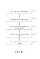
- FIG. 11is a flowchart illustrating an exemplary method of selecting information for display, and displaying the selected information, on a display device.
- modulemeans, but is not limited to, a software or hardware component, such as a field programmable gate array (FPGA) or an application specific integrated circuit (ASIC), which performs certain tasks.
- a modulemay advantageously be configured to reside on an addressable storage medium and be configured to execute on one or more processors.
- a modulemay include, by way of example, components, such as software components, object-oriented software components, class components and task components, processes, functions, attributes, procedures, subroutines, segments of program code, drivers, firmware, microcode, circuitry, data, databases, data structures, tables, arrays, and variables.
- componentssuch as software components, object-oriented software components, class components and task components, processes, functions, attributes, procedures, subroutines, segments of program code, drivers, firmware, microcode, circuitry, data, databases, data structures, tables, arrays, and variables.
- the functionality provided for in the components and modulesmay be combined into fewer components and modules or further separated into additional components and modules.
- FIG. 1is a block diagram illustrating the top-level components used in an exemplary system for converting data from one or more formats into a known useful format.
- multiple reference information sources 102are each in data communication with an information management module 105 .
- each of the reference information sourcesprovides information regarding automobile specifications to the information management module 105 .
- Reference Information Source Amay contain data regarding a Ford automobile
- Reference Information Source Bmay contain data regarding a Toyota automobile
- Reference Information Source Cmay contain data regarding a Mitsubishi automobile.
- one or more of the reference information sources 102provides scanned images of specification manuals.
- one or more of the reference information sources 102provides digital character data, such as ASCII text, that corresponds to the text information in a specification manual.
- the reference information source 102may also include images, such as may be stored in jpg (Joint Photographic Experts Group) format, that correspond to images included in a specification manual.
- the information management module 105is configured to receive data from multiple reference information sources 102 , in various formats, and convert the information into a known format that may be stored in a data store 104 and accessed by a user interface.
- the information management module 105is coupled to the data store 104 , which is configured to store the converted information in the known format. Because all of the data is stored in a known format, users may more easily search information from multiple specification manuals and access the information with a single interface.
- the data stored in the data store 104is advantageously tagged so that pages of a specification manual that may be relevant to a specific diagnostic procedure, repair procedure, or system of the automobile may be easily located and transmitted to the user.
- FIG. 2Ais a block diagram illustrating modules that are included in the information management module 105 of FIG. 1 .
- each of the modules illustrated in FIG. 2Ais located at the same location and interface with one another via direct data cable connections or a wired or wireless local area network (“LAN”), for example.
- LANlocal area network
- one or more of the modules illustrated in FIG. 2are located remote from the other modules and communicate with the document manager 115 via a wide area network (“WAN”), such as the Internet.
- WANwide area network
- the modules illustrated in FIG. 2Aare each software objects stored on a single computing device.
- the exemplary information management module 105includes a document manager 115 coupled to each of the other illustrated modules.
- the document manager 115comprises a computing device running an operating system, such as a PC, MAC, or LINUX based operating system.
- the document manager 115is advantageously configured to communicate with various devices and receive input in various formats.
- the document manager 115is configured to output information to various devices and in various formats.
- FIG. 2Bis a perspective view of an exemplary computer system 200 .
- the document manager 115comprises a computing device, such as the computer system 200 .
- each of the userssuch as an automobile repair shop, comprises one or more computing devices that are similar to the computer system 200 .
- the exemplary computer system 200comprises a display 210 coupled to a computer 220 .
- the computer system 210may be coupled to one or more computing devices via any type of networking connection.
- a plurality of user input devicesmay be coupled to the computer 200 , such as a keyboard 230 and a mouse 240 .
- the user input devicesmay also include a touch screen, joystick, trackball, and microphone, for example.
- peripheral devices listed above, and any other available peripheral devicesmay be coupled to the computer 110 via wired or wireless connections, and the computer 220 may be coupled to a network via a wired or wireless connection.
- the computer system 200 as described hereinis not limited to the device illustrated in FIG. 2 , but may be, for example, a personal digital assistant (PDA), cellular telephone, pager, or any computing device configured to display text, images or sounds (signs) to a user.
- PDApersonal digital assistant
- a portable computing device 250is in communication with the computer 220 via a wireless communication link.
- the portable computing device 250comprises a notebook or tablet computer.
- the portable computing device 250comprises a personal digital assistant (PDA), a cell phone, or any other suitable electronic device comprising a display and an information processor.
- the data generated by the information management module 105may be accessed by the computer system 200 , which may be located at an automobile repair shop, for example.
- the Data conversion modules 1 10are each configured to receive data from one or more different data sources, such as information providers at Mitsubishi, Hyundai, Ford, General Motors (“GM”).
- GMGeneral Motors
- one of the data conversion modules 110may be configured to receive automobile specification data in XML format from Mitsubishi Motors, while another data conversion module 110 may be configured to receive automobile specification data in PDF format from Ford Motors and yet another data conversion module 110 is configured to receive automobile specification data in another format from GM.
- the data conversion modules 110convert the received information into a known format and classify portions of the information into one or more of several views.
- these viewsinclude a table of contents view, a type view, and an extracted view.
- the table of contents viewindicates the hierarchal organization of pages included in the specification manual.
- each of the pages of a specification manualis stored in a database.
- An identifier for each of the pagesmay then be stored in a separate page list, and references to the identifiers of these pages may be organized in various manners.
- Each of these various organizations of pages, or organizations of page identifierscomprises a page view.
- a table of contents viewmay contain section headings included in the specification manual along with a pointer to the identified pages stored in a storage device.
- the table of contents viewprovides a sequential hierarchy of the information contained in a specification manual.
- a type viewclassifies pages of the specification manual into page types, which may include, for example, component, diagnostic, and special tools pages.
- the type viewmay further classify the pages into procedures so that by accessing the type view, a user may determine all pages that relate to a particular procedure category.
- a type viewmay classify pages into one of multiple different procedure types, such as DTC trouble shooting procedures, component inspection procedures, or repair procedures.
- a usermay easily locate all circuit diagrams, for example, by accessing the circuit diagram section within the type view of a manual.
- many of the pages in the table of contents vieware also referenced in the type view.
- the table of contents viewincludes all pages, while the type view includes a subset of the pages in the table of contacts view.
- identifiers for many pagesmay be included in multiple views and the identified pages may be located from different views.
- a specification manualmay be converted by the data conversion module 110 to include a special tools view, including an identifier for a page dealing with the use of an oil filter removal tool.
- the identifier for this same pagemay also be listed in the table of contents view as a subtopic of an engine care section of the specification manual, for example.
- identifiers for some pages of the specification manualare included in an extracted view, which further classifies content on the pages. For example, portions of a procedure page in the type view may be classified as (1) steps in the procedure or (2) reference information that is specific to that procedure.
- the data received from a data sourceidentifies pages that correspond with each of the views used by a particular data conversion module 110 .
- the pagesmay be classified into one or more views according to the data received from the data source.
- the data received from the data sourcedoes not include any information that classifies pages into views.
- the pagesare analyzed, by machine and/or human recognition, in order to classify the pages into one or more views.
- the information management module 105also includes a data store 125 , which may be any type of storage device, such as a hard drive or optical storage device.
- the information stored on the data store 125may be organized and physically stored on data store 125 according to any methods known in the art.
- the viewsare stored in the data store 125 .
- the data store 125is advantageously electronically coupled to the other modules of the information management module 105 so the views may be accessed by any of these modules and so that additional information may be stored and accessed on the data store 125 .
- Rule engine 120is configured to receive the pages that have been accessed by the data conversion modules 110 and to classify the pages into one or more categories.
- the rule engineassigns tags or labels to each page in the page store.
- the tagsreflect the various categorizations of each page. These tags are later used by the knowledge stream assembly module 130 .
- pages received from the data conversion modulesmay be classified into one or more of three groups, namely, global reference information, system reference information, or procedure descriptions.
- Global reference informationmay include, for example, pages including information that a user will want to access no matter what task they are working on. For example, pages including contact information for the vehicle manufacturer and information regarding translation of a VIN number into a model number may be classified as global reference information.
- System reference informationis information that relates to a particular automobile system, such as the transmission, engine, or brakes, for example.
- subsystemssuch as fuel injection, heating/cooling, and electrical subsystems related to an engine, for example, may also be included as automobile systems.
- the pages from the various specification manualsmay be categorized at varying levels according to the systems, or subsystems, to which the information relates.
- Procedure descriptionsgenerally describe a diagnostic, maintenance, or repair procedure (referred to herein generally as procedures). Typically, these procedures have specific steps for performing the procedures, and may also have pieces of reference information within them that are specific to each procedure. For example, repair procedures included in many specification manuals are organized into tables that include steps to be taken in performing each procedure. In one embodiment, a procedure description is in the form of a table or a list. In other embodiment, the procedure descriptions are organized in other formats known in the art.
- a symptom extraction module 190is coupled to the document manager 115 and is configured to identify symptoms for which diagnostic procedures may be relevant. The association of symptoms to a specific procedure may be useful in further categorizing those pages into a more granular view of the data.
- a knowledge stream assembly module 130is coupled to the document manager 115 . After the data pages have been categorized using the above-described modules, the knowledge stream assembly module compiles the pages into multiple enhanced procedure lists, referred to herein as “knowledge streams.” In one embodiment, the knowledge stream assembly module 130 processes the categorizations of the rules engine 120 in order to generate knowledge streams. For example, all categorized data that is relevant to a specific procedure may be combined into a knowledge stream including the procedure itself with steps of the procedure having links to all of the reference information related to that step, or the entire procedure. Further details regarding the generation and content of knowledge streams are included below with reference to FIG. 3 .
- An export module 195is coupled to the document manager 115 and is configured to change the format of the data maintained in the data store 125 according to the various requirements of users. For example, some users request that knowledge streams, or other data, be formatted for viewing on a portable device with specific dimensions, while other users may request knowledge streams in other formats and may also request copies of all specification manual pages referenced in a knowledge stream.
- the pages, or other data, requested by usersis converted by the export module 195 and stored in a data store 135 until retrieved by the requesting user.
- the requested datamay be formatted for storage as one or more XML documents.
- the converted datamay be stored in the data store 135 even after the requesting user has retrieved a copy of the data.
- the datamay be retrieved by other users that request the same data in the same format. This may be advantageous, for example, if a chain of automobile repair shops require data in a particular format.
- the datamay be accessed by any of the chain of repair shops without the need to reconvert the same data.
- the usermay manipulate the data for presentation on one or more display devices. For example, portions of the requested data may be extracted for viewing in separate panes that are presented on a display device.
- FIG. 3is a flow diagram illustrating the movement of data that is received from various information sources in the generation of knowledge streams. As illustrated in FIG. 3 , the process has been divided into steps performed by the data conversion module 110 , the rule engine 120 , the knowledge stream assembly module 130 , and the symptom extraction module 190 . While methods are described below with respect to specific modules, any of the steps illustrated in FIG. 3 may be performed by any of the other illustrated modules, or any other component of the information management module 105 .
- a step 105data from a data source is received by the data conversion module 10 .
- the datamay be in one of many different formats and may be received from various data sources.
- pages of a specification manualare received by the data conversion module 110 in a graphic format, such as in PDF, JPG, or TIF format.
- a graphic formatsuch as in PDF, JPG, or TIF format.
- the description belowoften refers to classification of pages, referring to pages of an automobile specification manual.
- any reference herein to a pageshould be read to cover any other data, such as a portion of a page or electronic data.
- the data conversion module 115classifies portions of the data into one or more of several views.
- each page of a specification manualis included in one or more views.
- these viewsinclude a table of contents view, a type view, and an extracted view.
- additional, or fewer, viewsmay be used in categorizing received data.
- the rule engine 120classifies and labels data, such as pages or portions of pages, into one or more classifications. These classifications may then be stored in the data store 125 for access by other modules of information management module 105 . As described above, in one embodiment, pages may be classified into one or more of three classifications, namely, global reference information, system reference information, or procedure descriptions.
- rulesare applied to the content of the received data, such as on a per page basis, in order to categorize and label each page, or portion of a page, properly.
- automatic rules, manual rules, and inherited rulesmay each be used to classify data.
- the automatic rulesare applied first, followed by inherited rules, and then manual rules.
- data that was not classified automaticallymay be classified according to manual or inherited rules.
- rulesare described further below.
- other types of rulesmay also be applied to the received data.
- an automatic ruleincludes an algorithm that identifies certain features on a page, assigns a score for each of these features, and based upon the total of the scores for the page, determines that the page should be classified into a particular category.
- Automatic rulesmay be generated by a human or by artificial intelligence training, for example. In either case, automatic rules are able to automatically take a piece of content, analyze the content, and determine one or more labels that should be applied to the content.
- Automatic rulesmay be defined to identify certain features of a procedure description, for example, so that a procedure description may be automatically identified. For example, if a symptom table, which is basically a table with a list of symptoms, includes a link to a particular page, the automatic rules may score the particular page as including a procedure description. If the word “procedure” appears in bold letters in a heading position, the data may get another score indicating that the data includes a procedure description. Other scores may also be assigned to a page indicating that the page is another category of information, such as a symptom table, for example. After the rules are applied to a page, the scores are summed and the page is categorized based on the various sums.
- threshold score totals for categorizing data into a specific categoryare established. For example, if four scores indicate that data contains a procedure description, and no other category received more than one score, the data may be categorized as containing a procedure description. In a similar manner, other categories may be assigned to data based upon common features that are in each type of information.
- automatic categorization of pagessuch as categorization of pages as procedure descriptions, may be performed by the data conversion module 110 .
- information that cannot satisfactorily be classified automaticallymay be classified manually by a person. For example, if a page has not been classified by an automatic rule, a person may view the page on a computer display device and determine the appropriate label, or labels, that should be applied to the page. This process generates a manual rule that the system can reapply in the future. Thus, the manual rule generation effort must be performed only once for a particular data set.
- Inherited rulesare a collection of manual rules applied to a new data set.
- the systemautomatically determines which rules from the collection are productive within the new data set.
- the inherited ruleslook for sections of data that correspond with data that has already been categorized.
- the section of datasuch as a page, a portion of a page, or multiple pages, may then inherent the same classifications as the data that was previously categorized. For example, if a set of classification rules is developed that applies to the specification manual for the 2003 Galant, the system may determine that some of the classification rules are applicable to the specification manual for the 2004 Galant. Thus, portions of the data from the 2004 Galant manual may be categorized using the categorizations that were used for the 2003 Galant manual.
- inherited rules that apply to particular dataare determined automatically so that manually generated rules may be used to categorize any portions for which inherited rules are not appropriate.
- inherited rulesare developed based on the analysis of multiple manuals and the determination of structures that are common across the analyzed manuals. Accordingly, the common structures in multiple manuals may be used to generate a template for inheritable rules.
- a knowledge stream assembly module 130After the data pages have been categorized using the above-described processes, a knowledge stream assembly module 130 generates multiple enhanced procedure lists, referred to as Knowledge Streams, based on the page categorizations received from the data conversion module 110 and rule engine 120 . At this point, all pages are labeled as a complete process description, a step in a process, a piece of reference material related to a particular process, a piece of reference information related to a particular system in the automobile, or a piece of reference information that is generally related to an automobile, for example. The knowledge stream assembly module 130 accesses these categorizations in order to generate knowledge streams.
- a knowledge streammay be directed specifically to global reference information so that a user may retrieve any global reference information from a single knowledge stream.
- the global reference informationmay also be compiled for use in other knowledge streams.
- the knowledge stream assembly module 130generates system reference information for use in one or more knowledge streams. For example, all information regarding a transmission system may be compiled for use in one or more knowledge streams. This exemplary compilation of transmission system information may include links to other similar procedures relating to the transmission system.
- a systemmay be either a broad system of the automobile, such as transmission, engine, or electrical, or system may include a subsystem, such as fuel injection, power seats, or brake pads, for example.
- information regarding fewer or more automobile systemsmay be generated at step 140 .
- the knowledge stream assembly module 130collects procedure description information for use in creating knowledge streams.
- a procedure descriptionis linked to information regarding a specific system by identifying a procedure as applying to that system.
- the data that has been categorized as a procedure descriptionmay be further categorized. For example, as illustrated in FIG. 3 , at a step 160 , steps of a procedure are processed and at a step 170 reference information included in a procedure description is processed. In one embodiment, steps 160 and 170 categorize the entire procedure description, or portions of the description, as either steps to be performed in a repair or diagnostic procedure, or as reference information. Thus, the data that is categorized as a procedure description in step 150 may be split into more narrow categorizations. For example, one type of reference information may include probable cause information, such as a list of things that might have caused the condition that is being diagnosed. Another type of reference information may be Diagnostic Trouble Codes (“DTC”), which is information read from an automobile's computer.
- DTCDiagnostic Trouble Codes
- a knowledge streammay include a procedure itself, along with steps of the procedure, and include links to reference information corresponding to specific steps, or corresponding to the entire procedure or the automobile in general.
- knowledge streamsare organized in a hierarchical structure. For example, a top level of the hierarchy may identify the specific knowledge streams, as well as other information that may help to identify the knowledge stream, such as a type of the knowledge stream.
- a number of foldersmay be linked to each knowledge stream, where the folders contain the various content items associated with the knowledge stream.
- a knowledge streammay contain individual steps in a process, pieces of reference information that are specific to a procedure, reference information for a system, and global reference information. Thus, by selecting a particular knowledge stream, various informational items may be easily retrieved by the user.
- FIG. 4is block diagram illustrating a data store 405 configured so that labels may be more easily updated according to the rules.
- pageswere typically associated directly with one or more labels for that page.
- the data store 405which may be a data base, for example, stores a page list, rules associated with each page, and labels for each of the pages, as generated by the rules.
- the page listincludes an identifier for each page, where the actual pages are stored separately.
- the page references stored in the page indexmay be viewed according to one or more views, which may also be stored in the data store 405 .
- rulesare generated for classification of particular pages (listed in the page index) so that a page may be classified according to the generated rules. Because rules are generated and stored, rather than just the specific classifications for the pages, these rules may be applied to subsequent pages, thus reducing the effort required to classify subsequent pages. For example, related pages, such as pages of a specification manual for a different year of the same model automobile, may be classified using the same rules. Accordingly, rules may be generated once and applied multiple times to a collection of pages if necessary. This approach accommodates the need to regenerate the base data (as changes are made, etc.) without losing the labeling effort that has already been performed.
- FIG. 5is a flow chart illustrating a method of updating an automotive repair and/or diagnosis database with information regarding the usefulness of particular repairs and/or diagnosis procedures. More generally, the method illustrated in the flow chart of FIG. 5 may be applied to updating a database with information indicating the usefulness of particular informational items by users.
- a technicianinspects an automobile.
- the technicianmay inspect various components of the vehicle based upon, for example, information provided by an owner of the vehicle or standard checkup items.
- the techniciantypically inspects at least one component of the automobile and records the status of that component.
- FIG. 5will be described with specific reference to inspection and diagnosis of automobile brakes.
- the systems and methods described hereinare not only applicable to brake systems, but may be applied to any component that may be analyzed, diagnosed, and serviced.
- a technicianmay analyze and record brake fluid levels, brake pad thickness, and caliper wear, for example. The technician may then record observations relating to each of these items in various formats.
- the techniciansimply notes whether the item is within allowable specifications or if the item needs further diagnosis and/or repair.
- the technicianrecords more exact data for each item, such as an estimate of the brake fluid level and a thickness of the brake pads.
- the computing devicemay be one of many devices, but advantageously is a mobile device that is configured to communicate with a central computer.
- a tablet computer or a personal digital assistant (“PDA” )may be used by a technician to enter the inspection data.
- PDApersonal digital assistant
- the technicianmay enter one or more inspection results for each item inspected.
- the technicianenters a thickness of brake pads, such as 2 mm.
- the technicianmay simply note that the pads require repair and/or further diagnosis or that the pads are of an acceptable thickness.
- the resultsare advantageously transmitted to a central computer, typically having greater storage and processing capabilities than the computing device. Transmission of the results may be performed either via a wired or a wireless link and may be accomplished using any available communication protocol.
- one or more diagnostic and/or repair proceduresare selected, based upon the inspection results and the acceptable specifications for the inspected items.
- the central computerdetermines the one or more diagnostic and/or repair procedures that should be performed by the technician.
- a mobile computing device that the technician uses to enter the inspection resultsmay be configured to determine the one or more diagnostic and/or repair procedures.
- the one or more determined proceduresare advantageously displayed to the technician on the computing device.
- the displayed informationincludes specific steps to be performed in completing the one or more procedures. For example, if the central computer or the technician computing device determines that a brake pad is too thin, the determined procedure may be to replace the brake pad. Thus, the technician is informed of this diagnosis on the technician computing device. In addition, the technician may also be provided with specific steps to be performed in replacing the brake pad.
- the recommended procedureis performed by the technician.
- the brake padis replaced by following the procedure provided on the technician computing device.
- an effectiveness of the performed procedureis reported.
- the effectiveness of some proceduresmay be determined by the technician immediately after performing the procedure, while the effectiveness of other procedures may not be determined until after the automobile has been returned to the owner and the vehicle has operated for a period of time. In either case, an effectiveness determination is entered into either the technician computing device, the central computer, or any other computing device that is in communication with the central computer. For example, if a particular procedure does not remedy the diagnosed symptom, a poor rating may be assigned to the procedure. Likewise, if a particular procedure does remedy the diagnosed symptom, an excellent rating may be assigned to the procedure. These ratings may be numerical, ranging from 1 to 10 or 1 to 100, for example, or composed of alphabetic ratings, such as A-F, for example. Any other rating system may also be used in conjunction with the described systems and methods.
- the effectiveness of the performed procedureis recorded in a database.
- the diagnosis for which the procedure was recommendedis also recorded in the database.
- the central computermay then analyze the effectiveness of the recommended procedure with respect to the diagnosis that caused the procedure to be recommended. If multiple procedures have been performed in response to the same or similar symptoms, the central computer may then determine which procedures are the most effective for remedying the symptoms. In this way, the effectiveness of multiple procedures for treating a diagnosed symptom may be rated. Thereafter, the database that stores recommended procedures linked to diagnoses may be updated so that the most effective procedure for each diagnosed symptom is provided to the technician as the most effective procedure. In one embodiment, the technician is provided with multiple choices for procedures to perform in response to a diagnosis.
- the technician computing devicemay list up to three procedures that have the highest effectiveness rating for a diagnosed symptom. The technician may then have the opportunity to select one of the procedures and, in response to the selection, may be presented with a knowledge stream for the selected procedure, or a list of steps to perform in completing the procedure.
- FIG. 6is a simplified diagram illustrating an exemplary configuration of information in a graphical user interface (“GUI”) 600 . While the configuration of information illustrated in FIG. 6 may be used for display of information related to any object, the GUI 600 illustrates information related to a vehicle, such as an automobile.
- the exemplary GUI 600includes a vehicle information pane 610 , task information pane 620 , and reference information pane 630 .
- the arrangement of information as illustrated in FIG. 6advantageously provides a viewer with various types of information that are each related to a particular task.
- FIG. 6is described below with specific reference to display of information related to vehicles. However, the display configuration and methods for displays discussed herein are expressly contemplated for use with information related to any object.
- the vehicle information pane 610contains information regarding a particular vehicle that is being diagnosed, repaired, and/or otherwise inspected.
- the vehicle information panemay contain a make, model, year, and options of an automobile.
- the vehicle information pane 610may further include customer information, such as address, phone number, and prior repair orders and invoices.
- customer informationsuch as address, phone number, and prior repair orders and invoices.
- a user viewing the GUI 600may view many types of information regarding the vehicle under inspection.
- the task information pane 620contains information regarding a particular task (referred to herein also as a procedure) that may be performed on the vehicle indicated in the vehicle information pane 610 .
- the procedures that may be displayed in the task information pane 620include, for example, diagnostic and repair procedures.
- the task information pane 620may include multiple steps that may be performed in diagnosing a symptom and may later display multiple steps in repairing a particular diagnosed symptom. For example, if a user is an automobile repair technician, the task information pane 620 may include steps for diagnosing a problem with an automobile's brake system. The steps may be divided into several sub steps, or categories, that may be iteratively displayed in the task information pane 620 .
- the reference information pane 630contains various types of reference information, from various reference sources, that is related to the currently displayed task information for the vehicle indicated in the vehicle information pane 610 .
- the task information pane 620includes a diagnostic procedure for checking a leaking dump valve of an automobile
- the reference information pane 630may display reference information indicating the proper method for removal and installation of a hydraulic control unit.
- the reference information pane 630may display items such as wiring diagram or special tool information that may be useful for completion of the indicated task.
- the task information pane 620includes one or more buttons or tabs that may be selected in order to display particular reference information in the reference information pane 630 .
- a button or tabmay be labeled to indicate a type of reference information that is available for viewing, such as symptom help, components/tools, system info, and general info.
- the usermay determine which type of reference information may be most useful in completing the task and may select one or more of the types of reference information available with respect to a particular task. Because every technician has unique training and experience, not every technician requires the same reference information. Accordingly, the buttons and/or tabs located in the task information pane 620 advantageously allow each technician to determine which types of reference information they would like to view in order to more efficiently complete the task.
- the configuration of information as shown in exemplary FIG. 6provides information that typically may only be found in multiple information sources.
- a typical automobile repair shopmay use a specification manual for a certain make and model of automobile in order to diagnose symptoms of a subject automobile.
- certain reference informationsuch as the location of particular electrical components, the manufacturer's suggested torque settings, or instructions for using a particular tool referred to in the diagnosis procedure, may not be located on the same page as the diagnosis procedure.
- the reference informationmay be in another book or another section of the specification manual. In either case, additional effort and time is required for the technician to locate the proper reference information.
- the relevant reference informationof any type, is advantageously displayed next to the procedure steps.
- the reference informationis automatically updated as the information in the task information pane 620 is changed. Accordingly, a technician viewing the GUI 600 does not need to access any other reference information, valuable man hours are spared, and efficiency increases.
- the layout and immediate availability of relevant reference informationmay also increase the learning capabilities of the viewing technician.
- the technicianis not required to shift their mental focus from the task indicated in the task information pane 620 to the more menial task of locating reference information that may be helpful or required to complete the task, the technician is more likely to understand and retain the task information and the related reference information.
- the layout of information as illustrated in FIG. 6may increase employee productivity by increasing employee learning capacity.
- FIG. 7is an exemplary GUI 700 including the configuration of panes as discussed above with respect to FIG. 6 .
- FIG. 7includes a vehicle information pane 710 a task information pane 720 and a reference information pane 730 .
- the vehicle information paneindicates that the information in the vehicle information pane 710 , the task information pane 720 , and the reference information pane 730 is related to a Ford E-series 2004 vehicle.
- the vehicle information pane 710also includes a customer concerns/request portion 712 , wherein a customer's concerns, along with the status of resolving each concern, may be tracked.
- a technician's symptoms portion 714is linked to the customer concerns/request portion 712 and includes a technician's notes related to the particular customer concern.
- a task type menu 716lists one or more tasks that may be selected for display in the task information pane 720 .
- the available tasks listed in the task type menu 716include DTC troubleshooting; symptom troubleshooting; remove, replace, install, and repair; service, adjust and clean; and test, check and inspect.
- additional types of tasksmay be included and the task types may be further divided into more task types.
- a system menu 717lists one or more systems, or subsystems, of the vehicle on which the task selected in the task type menu 716 may be performed. For example, if the symptom troubleshooting task is selected in the task type menu 716 , the system menu 717 may list vehicle systems on which knowledge streams for symptom troubleshooting are available. These systems may include, for example, exhaust system, support system, engine, steering system, power train, electrical system, coolant system, fuel system, and brake system.
- system menu 717may also include subsystems, such as, muffler, tailpipe, fuel tank, shock absorbers, coil springs, drum brake, fuel line, accelerator, brake pedal, distributor, differential, master break cylinder, disk brake, transmission, spark plug wires, exhaust manifold, engine, radiator, alternator, coolant reservoir, intake manifold, batteries, break line, and steering wheel.
- subsystemssuch as, muffler, tailpipe, fuel tank, shock absorbers, coil springs, drum brake, fuel line, accelerator, brake pedal, distributor, differential, master break cylinder, disk brake, transmission, spark plug wires, exhaust manifold, engine, radiator, alternator, coolant reservoir, intake manifold, batteries, break line, and steering wheel.
- the system menu 717is populated with selectable items in response to the selection of a task type from the task type menu 716 .
- the systems that are displayed in the system menu 717are those systems for which task information is available on the currently selected vehicle. For example, in the embodiment of FIG. 7 , a Ford E-Series 2004 vehicle is selected. If a remove, replace install and repair task type is selected in the task type menu 716 , the system menu 717 may display, among other systems, manual transmission and automatic transmission. However, if another vehicle is selected that is not available with a manual transmission, the system menu 717 may not display manual transmission as a selection option.
- the systems displayed in the system menu 717 for a selected task typeare the same for any vehicle, but only certain systems are selectable by a user.
- the task information pane 720includes information for repairing soft/excessive brake pedal travel.
- the specific task display in the task information pane 720e.g., “soft/excessive brake pedal travel . . . ” is selected from a list of one or more tasks related to the selected task type and the selected system.
- a first procedure in this particular taskis titled “Check for leaking dump valve.”
- One of the steps in this procedureincludes, “Remove the rubber caps from the two HCU low pressure accumulators.”
- the reference information pane 730displays relevant reference information. For example, in the illustration of FIG. 7 , the reference information pane displays information regarding the removal and installation of a Hydraulic Control Unit.
- the reference information pane 730includes multiple tabs 732 A- 732 D, which may be selected in order to change the type of reference information displayed. For example, if the user selects the components/tools tab 732 B, the reference information pane 730 will be updated with information regarding special tools that are relevant to the procedure for repairing soft/excessive brake pedal travel.
- the reference information tabs 732may be automatically updated, or added to, based upon the information displayed in the vehicle pane 720 and/or the task information pane 720 . For example, various steps of a task that are displayed in the task information pane 720 may have specific reference information that is relevant to the particular step.
- the reference information tabs 732may be automatically updated to include additional tabs corresponding to relevant reference information.
- the tabs 732may then be selected in order to display the corresponding reference information in the reference information pane 730 .
- FIG. 8is a simplified diagram illustrating an exemplary configuration of information in a GUI 800 . While the configuration of information illustrated in FIG. 8 may be used for display of information related to any object, the GUI 800 illustrates information related to a vehicle, such as an automobile. In the embodiment of FIG. 8 , a task information pane 810 is located next to a reference information pane 820 . The GUI 800 does not include a separate pane for vehicle information. However, in one embodiment, the vehicle information may be displayed in a separate window, or in either the task information pane 810 or reference information pane 820 when selected. For example, the vehicle information may be displayed on a display device as an alternate to display of the task information pane 810 and the reference information pane 820 as shown in FIG. 8 .
- the GUI 800updates the reference information according to the currently displayed task information. Accordingly, the user is provided with reference information that may otherwise only be found in multiple separate reference manuals. Because the relevant reference information is easily available to the user, the user's focus on the displayed task is maintained and the user's comprehension of the task may be enhanced.
- FIG. 9is a simplified diagram of a GUI 900 including two primary panes, specifically, a repair order/task information pane 910 (also referred to herein as a task information pane) and a solution/search/reference information pane 920 (also referred to herein as a reference information pane).
- the two primary panesare divided by an adjustable divider 930 that may be moved in either direction to change the sizes of the primary panes.
- FIG. 10Ais an exemplary GUI 1000 that is configured similar to the layout of simplified GUI 900 .
- the GUI 1000includes a task information pane 910 , a reference information pane 920 , and adjustable divider 930 in the same orientation as FIG. 9 .
- a repair order/task navigation pane 950may include one or more tabs, buttons, or other selection indicator, related to repair orders, tasks, and diagnostic information from a scanning device, such as a PicoScope.
- the navigation pane 950may include other tabs that may be selected in order to display various types of information in the task information pane 910 .
- the repair order/task navigation pane 950includes a repair order (“RO” ) list tab 952 , an RO in progress tab 954 , a task/completion chart tab 956 , and a scan/oscilloscope (Oscope) tab 958 .
- ROrepair order
- Oscopescan/oscilloscope
- each of the tabs 952 , 954 , 956 , and 958initiate display of different types of information in the task information pane 910 .
- the task/completion chart tab 956is selected. Accordingly, task information is displayed in the task information pane 910 .
- the task information pane 910will display a list of one or more repair orders that have been entered into the database.
- FIG. 10Bis a partial screen shot illustrating the task information pane 910 when the RO list tab 952 is selected.
- FIG. 10Cis a partial screen shot illustrating the task information pane 910 when the RO in progress tab 954 is selected.
- the Scan/Oscope tab 958is selected, the task information pane 910 displays information regarding available diagnostic tests.
- FIG. 10Dis a partial screen shot illustrating the task information pane 910 when the Scan/Oscope tab 958 is selected. As shown in exemplary FIG. 10D , two diagnostic tests, a car code scan tool application and a PicoScope application, are available for use.
- a task information navigation pane 960includes tabs, buttons, or other navigation indicators, allowing the user to navigate task information displayed in the task information pane 910 .
- the task information navigation pane 960includes several groups of selectable buttons.
- the task information navigation pane 960includes multiple task step tabs 962 .
- task step tabsthe labeled 1-11 are illustrated.
- the task step tab 962 Acorresponding to a task step tab 3 , is selected in the GUI 1000 .
- the task information pane 910displays information regarding a third step in the selected task. The user may jump to any numbered step in the task by selecting the corresponding task step tab 962 .
- a solution/search/reference navigation pane 970includes one or more tabs, buttons, or other selectable indicators that allow the user to select a type of information for display in the solution/search/reference information pane 920 .
- this paneincludes a solutions button 972 , a search button 974 , and a reference button 976 .
- the solutions button 972selects for display in the reference information pane 920 , a list of possible tasks that may be performed on the selected vehicle for the selected symptoms.
- FIG. 10Eis a partial screen shot illustrating an exemplary display of the reference information pane 920 when the solutions button 972 is selected.
- the search button 974selects for display in the reference information pane 920 one or more search fields that may be used to search the database of procedures.
- FIG. 10Fis a partial screen shot illustrating an exemplary reference information pane 920 when the search button 974 is selected.
- reference button 976when a reference button 976 is selected, information related to one of multiple types of reference information is displayed in the reference information pane 920 .
- the reference type navigation pane 980indicates the type of reference information displayed in the reference information pane 920 when the reference button 976 is selected.
- reference button 976is selected and a task is selected for identifying fluid leaks.
- the software applicationlocates reference information related to the task of identifying fluid leaks, which includes a fuel injection line routing diagram, such as displayed in FIG. 10A .
- the 10Amay be selected for display by selecting an electrical/diagrams button 984 from the reference type navigation pane 980 . If other types of reference information are desired, the other reference type navigation buttons 981 - 987 may be selected. In one embodiment, if no reference information of the type selected in the reference type navigation pane 980 is available, the particular reference type navigation button will not be selectable by the user.
- the reference information displayed in the reference information pane 920relates to the current task information displayed in the task information pane 910 . Accordingly, the user may more easily visualize the procedures necessary to complete a task using all available reference information.
- FIG. 11is a flowchart illustrating an exemplary method of selecting information for display, and displaying the selected information, on a display device.
- the method of FIG. 11is performed by a computer system 200 ( FIG. 2 ) located at an automobile repair shop.
- the computer system 200includes the portable computing device 250 that is wirelessly coupled to the computer 220 .
- the portable computing deviceincludes a display on which the procedure and reference information is displayed.
- the method of FIG. 11may be performed by the document manager 115 or any other computing device that has access to the information generated by the document manager 115 .
- 11is described as performed by a computer system 200 located at an automobile repair shop, wherein the task and reference pane are displayed on a portable computing device 250 that is in communication with the computer 220 .
- the completion of the various method stepsmay be performed solely by the portable computing device, the computer 210 , or by a combination of the portable computing device 250 and the computer 210 .
- the methodmay be performed by other computing devices or combinations of computing devices.
- an inputis received indicating a selected object.
- the objectmay be any object on which procedures, such as diagnostic or repair procedures, may be performed.
- the objectcomprises a vehicle.
- a userselects a particular make, model, and year of an automobile using an input device, such as a keyboard 230 and/or a mouse 240 that is coupled to the computer 220 .
- the userenters information into the portable computing device 250 using a stylus, keypad, keyboard, or microphone of the portable computing device. For example, the user may select a 1998 Ford Mustang by navigating one or more pull-down menus displayed on the portable computing device 250 .
- the input devicemay be an on-board diagnostic (OBD) system scanning tool connected to an OBD connector of an automobile.
- OBD system scanning toolmay determine the make, model, and year of the automobile and provide this data to the computer system 200 via the portable computing device 250 , for example.
- an inputis received at the portable computing device 250 indicating a procedure that has been selected.
- the procedureis automatically selected based on information received from an OBD connector of the selected vehicle.
- a proceduresuch as a diagnostic or repair procedure is selected by the user based on one or more symptoms of the vehicle.
- the user of the computer system 200such as an automobile technician, enters one or more symptoms of the automobile into the portable computing device 250 that is wirelessly coupled to the computer system 200 and the computer system 200 determines one or more procedures that may be performed on the automobile. Alternatively, this determination may be performed entirely by the portable computing device. The user may then select a specific procedure from the recommended procedures that are selected by one or more devices of the computer system 200 .
- a display area of the display devicesuch as an LCD screen of the portable computing device 250 , is allocated for concurrent display of the task pane and the reference pane.
- the portable computing device 250 that is carried by the automobile technicianmay be horizontally divided into two panes, such as is illustrated in FIG. 10A .
- the area of the panesmay be automatically adjusted by the computing device that is displaying the panes or, alternatively, may be manually adjusted by the user of the portable computing device 250 .
- the panesmay be displayed on any other computing device, such as the display device 210 .
- FIG. 10Aillustrates a task pane 910 that displays a task step and multiple task step tabs 962 .
- the task pane 910displays information regarding a particular procedure that may be performed on the automobile.
- the usermay move from one task step to another by selecting a corresponding task step tab 962 .
- the usermay jump to a next step by selecting a next step link 963 , such as the next step link 963 labeled “Go to Step 4 ” in FIG. 10A .
- the next step link 963is included as a portion of the task step information.
- a particular task stepmay include more than one next step link 963 for selection by a user.
- the usermay navigate between multiple task steps in various manners.
- the portable computing device 250displays reference information in the reference pane, such as the reference pane 920 of FIG. 10A .
- the reference pane 920displays information that is related to the information currently displayed in the task pane 910 and the selected vehicle.
- the reference informationcontains information that may be useful to the technician in completing the selected procedure.
- the reference informationmay include information regarding symptoms, components, tools, system info, and general info, for example.
- the usermay select from multiple reference information items that are related to the current procedure and/or task step. Accordingly, the user may determine which type of reference information may be most useful in completing the task and may select one or more of the types of reference information available with respect to a particular task.
- the buttons and/or tabs located in the reference pane 920advantageously allow each technician to determine which types of reference information they would like to view in order to more efficiently complete the task.
- the reference pane 920includes a toolbar 990 that displays reference information tabs 992 that are currently available for selection by the user. Any of these tabs 992 may be selected by the user in order to change the display of reference information in the reference pane 920 .
- the toolbar 990also includes a history of the reference information that has previously been displayed. As illustrated in FIG.
- reference information related to “FUEL INJECTION LINE”is currently displayed in the reference pane
- reference information tabs 992correspond to “Component Locations”, “SMU-REVISED FUEL SYSTEM”,” and “TSBs”reference information.
- These additional reference information tabs 992may correspond to reference information that has previously been displayed in the reference pane 920 and/or the tabs 992 may correspond to additional reference information that is related to the information currently displayed in the task pane 910 .
- the usermay easily re-display a reference information item that has already been viewed by clicking on the appropriate tab 992 in the toolbar 990 .
- the graphical user interfacedisplays information that may reduce the time required to perform a selected procedure.
- the automatic display of reference information related to the specific procedure or sub-procedure that is currently displayed in the task panereduces the need for the technician to locate the reference information in another source.
- the display of reference information that is related to the information in the task panereduces the need for the technician to memorize or otherwise become familiar with the reference information.
- Much of the reference informationmay be information that is infrequently used by the technician and, thus, requiring the technician to commit the reference information to memory or locate the reference information in one or more reference materials may reduce the efficiency and increase the time required to complete the procedure.
Landscapes
- Engineering & Computer Science (AREA)
- General Engineering & Computer Science (AREA)
- Theoretical Computer Science (AREA)
- Human Computer Interaction (AREA)
- Physics & Mathematics (AREA)
- General Physics & Mathematics (AREA)
- Management, Administration, Business Operations System, And Electronic Commerce (AREA)
Abstract
Description
Claims (26)
Priority Applications (1)
| Application Number | Priority Date | Filing Date | Title |
|---|---|---|---|
| US11/035,751US7444216B2 (en) | 2005-01-14 | 2005-01-14 | User interface for display of task specific information |
Applications Claiming Priority (1)
| Application Number | Priority Date | Filing Date | Title |
|---|---|---|---|
| US11/035,751US7444216B2 (en) | 2005-01-14 | 2005-01-14 | User interface for display of task specific information |
Publications (2)
| Publication Number | Publication Date |
|---|---|
| US20060161313A1 US20060161313A1 (en) | 2006-07-20 |
| US7444216B2true US7444216B2 (en) | 2008-10-28 |
Family
ID=36685046
Family Applications (1)
| Application Number | Title | Priority Date | Filing Date |
|---|---|---|---|
| US11/035,751Active2026-08-07US7444216B2 (en) | 2005-01-14 | 2005-01-14 | User interface for display of task specific information |
Country Status (1)
| Country | Link |
|---|---|
| US (1) | US7444216B2 (en) |
Cited By (50)
| Publication number | Priority date | Publication date | Assignee | Title |
|---|---|---|---|---|
| US20070016465A1 (en)* | 2005-07-15 | 2007-01-18 | Sap Aktiengesellschaft | Mechanism to control delegation and revocation of tasks in workflow system |
| US20080216012A1 (en)* | 2005-08-26 | 2008-09-04 | United Space Alliance, Llc | Instruction and training tool |
| US20090184812A1 (en)* | 2007-08-09 | 2009-07-23 | Michael Drew | User Configured Display System For Motor Vehicle |
| US20100138701A1 (en)* | 2008-12-03 | 2010-06-03 | Snap-On Incorporated | Method and System for Retrieving Diagnostic Information |
| US20110153150A1 (en)* | 2007-08-09 | 2011-06-23 | Michael Drew | Vehicle Tuner And Display Module And Docking Station |
| US20110191722A1 (en)* | 2010-02-04 | 2011-08-04 | Gill George M | Nested controls in a user interface |
| US8160767B1 (en)* | 2006-06-08 | 2012-04-17 | Thompson Bernie C | Vehicle diagnostic tool—utilizing volumetric efficiency |
| WO2012056754A1 (en)* | 2010-10-28 | 2012-05-03 | 本田技研工業株式会社 | Fault diagnosis method and fault diagnosis device |
| US8239094B2 (en) | 2008-04-23 | 2012-08-07 | Spx Corporation | Test requirement list for diagnostic tests |
| US20120209570A1 (en)* | 2009-10-19 | 2012-08-16 | Hiroki Uchiyama | Diagnosis system and diagnosis method for construction machine |
| US20120239654A1 (en)* | 2009-12-04 | 2012-09-20 | Nec Corporation | Related document search system, device, method and program |
| US20120290106A1 (en)* | 2011-05-13 | 2012-11-15 | Still Gmbh | Method for the management of industrial trucks and an industrial truck |
| US8412402B2 (en) | 2006-06-14 | 2013-04-02 | Spx Corporation | Vehicle state tracking method and apparatus for diagnostic testing |
| US8423226B2 (en) | 2006-06-14 | 2013-04-16 | Service Solutions U.S. Llc | Dynamic decision sequencing method and apparatus for optimizing a diagnostic test plan |
| US8428813B2 (en) | 2006-06-14 | 2013-04-23 | Service Solutions Us Llc | Dynamic decision sequencing method and apparatus for optimizing a diagnostic test plan |
| US8463953B2 (en) | 2010-08-18 | 2013-06-11 | Snap-On Incorporated | System and method for integrating devices for servicing a device-under-service |
| US8560168B2 (en) | 2010-08-18 | 2013-10-15 | Snap-On Incorporated | System and method for extending communication range and reducing power consumption of vehicle diagnostic equipment |
| US8615773B2 (en) | 2011-03-31 | 2013-12-24 | Honeywell International Inc. | Systems and methods for coordinating computing functions to accomplish a task using a configuration file and standardized executable application modules |
| US8648700B2 (en) | 2009-06-23 | 2014-02-11 | Bosch Automotive Service Solutions Llc | Alerts issued upon component detection failure |
| US8726084B2 (en) | 2011-10-14 | 2014-05-13 | Honeywell International Inc. | Methods and systems for distributed diagnostic reasoning |
| US8751777B2 (en) | 2011-01-28 | 2014-06-10 | Honeywell International Inc. | Methods and reconfigurable systems to optimize the performance of a condition based health maintenance system |
| US8754779B2 (en) | 2010-08-18 | 2014-06-17 | Snap-On Incorporated | System and method for displaying input data on a remote display device |
| US8762165B2 (en) | 2006-06-14 | 2014-06-24 | Bosch Automotive Service Solutions Llc | Optimizing test procedures for a subject under test |
| US20140207771A1 (en)* | 2013-01-21 | 2014-07-24 | Snap-On Incorporated | Methods and Systems for Mapping Repair Orders within a Database |
| US20140244213A1 (en)* | 2011-02-21 | 2014-08-28 | Snap-On Incorporated | Diagnostic Baselining |
| US8832649B2 (en) | 2012-05-22 | 2014-09-09 | Honeywell International Inc. | Systems and methods for augmenting the functionality of a monitoring node without recompiling |
| US8832716B2 (en) | 2012-08-10 | 2014-09-09 | Honeywell International Inc. | Systems and methods for limiting user customization of task workflow in a condition based health maintenance system |
| TWI466009B (en)* | 2012-01-18 | 2014-12-21 | Acer Inc | User interface information display method |
| US8983785B2 (en) | 2010-08-18 | 2015-03-17 | Snap-On Incorporated | System and method for simultaneous display of waveforms generated from input signals received at a data acquisition device |
| US8990770B2 (en) | 2011-05-25 | 2015-03-24 | Honeywell International Inc. | Systems and methods to configure condition based health maintenance systems |
| US9081883B2 (en) | 2006-06-14 | 2015-07-14 | Bosch Automotive Service Solutions Inc. | Dynamic decision sequencing method and apparatus for optimizing a diagnostic test plan |
| US9117321B2 (en) | 2010-08-18 | 2015-08-25 | Snap-On Incorporated | Method and apparatus to use remote and local control modes to acquire and visually present data |
| US9330507B2 (en) | 2010-08-18 | 2016-05-03 | Snap-On Incorporated | System and method for selecting individual parameters to transition from text-to-graph or graph-to-text |
| US9499128B2 (en) | 2013-03-14 | 2016-11-22 | The Crawford Group, Inc. | Mobile device-enhanced user selection of specific rental vehicles for a rental vehicle reservation |
| US20160342451A1 (en)* | 2015-05-19 | 2016-11-24 | The United States Of America As Represented By The Secretary Of The Navy | Dynamic error code, fault location, and test & troubleshooting user experience correlation/visualization systems and methods |
| US9513789B2 (en) | 2013-10-24 | 2016-12-06 | Alldata Llc | Vehicle diagnostic systems and methods |
| US9633492B2 (en) | 2010-08-18 | 2017-04-25 | Snap-On Incorporated | System and method for a vehicle scanner to automatically execute a test suite from a storage card |
| US9639995B2 (en) | 2015-02-25 | 2017-05-02 | Snap-On Incorporated | Methods and systems for generating and outputting test drive scripts for vehicles |
| US20170235720A1 (en)* | 2016-02-11 | 2017-08-17 | GM Global Technology Operations LLC | Multilingual term extraction from diagnostic text |
| US20180365222A1 (en)* | 2017-06-19 | 2018-12-20 | GM Global Technology Operations LLC | Phrase extraction text analysis method and system |
| US10705686B2 (en)* | 2014-10-30 | 2020-07-07 | Snap-On Incorporated | Methods and systems for taxonomy assist at data entry points |
| US11144888B2 (en) | 2015-10-02 | 2021-10-12 | Snap-On Incorporated | Method and system for augmenting real-fix tips with additional content |
| US20220019338A1 (en)* | 2020-07-17 | 2022-01-20 | Honeywell International Inc. | Smart tab interface controls |
| US11386401B2 (en)* | 2019-01-20 | 2022-07-12 | Mitchell Repair Information Company, Llc | Methods and systems to provide packages of repair information based on component identifiers |
| US11429936B2 (en) | 2015-10-02 | 2022-08-30 | Snap-On Incorporated | System and method for dynamically-changeable displayable pages with vehicle service information |
| US11449204B2 (en) | 2020-09-21 | 2022-09-20 | MBTE Holdings Sweden AB | Providing enhanced functionality in an interactive electronic technical manual |
| US11929068B2 (en) | 2021-02-18 | 2024-03-12 | MBTE Holdings Sweden AB | Providing enhanced functionality in an interactive electronic technical manual |
| US11947906B2 (en) | 2021-05-19 | 2024-04-02 | MBTE Holdings Sweden AB | Providing enhanced functionality in an interactive electronic technical manual |
| US12242711B2 (en) | 2021-05-19 | 2025-03-04 | MBTE Holdings Sweden AB | Providing enhanced functionality in an interactive electronic technical manual |
| US12360651B2 (en) | 2022-11-02 | 2025-07-15 | MBTE Holdings Sweden AB | Providing enhanced functionality in an interactive electronic technical manual |
Families Citing this family (74)
| Publication number | Priority date | Publication date | Assignee | Title |
|---|---|---|---|---|
| US6566883B1 (en) | 1999-11-01 | 2003-05-20 | Midtronics, Inc. | Electronic battery tester |
| US8872517B2 (en) | 1996-07-29 | 2014-10-28 | Midtronics, Inc. | Electronic battery tester with battery age input |
| US6850037B2 (en) | 1997-11-03 | 2005-02-01 | Midtronics, Inc. | In-vehicle battery monitor |
| US7705602B2 (en) | 1997-11-03 | 2010-04-27 | Midtronics, Inc. | Automotive vehicle electrical system diagnostic device |
| US8958998B2 (en) | 1997-11-03 | 2015-02-17 | Midtronics, Inc. | Electronic battery tester with network communication |
| US7446536B2 (en) | 2000-03-27 | 2008-11-04 | Midtronics, Inc. | Scan tool for electronic battery tester |
| US7398176B2 (en) | 2000-03-27 | 2008-07-08 | Midtronics, Inc. | Battery testers with secondary functionality |
| US9255955B2 (en) | 2003-09-05 | 2016-02-09 | Midtronics, Inc. | Method and apparatus for measuring a parameter of a vehicle electrical system |
| US9018958B2 (en) | 2003-09-05 | 2015-04-28 | Midtronics, Inc. | Method and apparatus for measuring a parameter of a vehicle electrical system |
| US7154276B2 (en) | 2003-09-05 | 2006-12-26 | Midtronics, Inc. | Method and apparatus for measuring a parameter of a vehicle electrical system |
| US8344685B2 (en) | 2004-08-20 | 2013-01-01 | Midtronics, Inc. | System for automatically gathering battery information |
| US9496720B2 (en) | 2004-08-20 | 2016-11-15 | Midtronics, Inc. | System for automatically gathering battery information |
| US8019503B2 (en)* | 2007-06-28 | 2011-09-13 | Innova Electronics Corp | Automotive diagnostic and remedial process |
| US8068951B2 (en)* | 2005-06-24 | 2011-11-29 | Chen Ieon C | Vehicle diagnostic system |
| US9117319B2 (en)* | 2005-06-30 | 2015-08-25 | Innova Electronics, Inc. | Handheld automotive diagnostic tool with VIN decoder and communication system |
| US20070043487A1 (en)* | 2005-08-19 | 2007-02-22 | Snap-On Incorporated | Method and system for providing vehicle-service alerts to a vehicle technician |
| US7702487B2 (en) | 2006-04-11 | 2010-04-20 | Invensys Systems, Inc. | System management user interface providing user access to status information for process control system equipment including displayed propagated status in a navigation pane |
| US7729887B2 (en)* | 2006-04-11 | 2010-06-01 | Invensys Systems, Inc. | System management user interface providing user access to status information for process control system equipment including a status monitor |
| US20070294090A1 (en)* | 2006-06-20 | 2007-12-20 | Xerox Corporation | Automated repair analysis using a bundled rule-based system |
| US7987028B2 (en)* | 2006-09-12 | 2011-07-26 | Spx Corporation | Method and apparatus for reading and erasing diagnostic trouble codes from a vehicle |
| US7689334B2 (en)* | 2006-09-28 | 2010-03-30 | Perkins Engines Company Limited | Engine diagnostic method |
| US20080208609A1 (en)* | 2007-01-26 | 2008-08-28 | Service Repair Solutions, Inc. | Smart inspections |
| US9026400B2 (en) | 2007-06-28 | 2015-05-05 | Innova Electonics, Inc. | Diagnostic process for home electronic devices |
| US8370018B2 (en)* | 2007-06-28 | 2013-02-05 | Innova Electronics, Inc. | Automotive diagnostic process |
| GB2463829B (en)* | 2007-07-17 | 2012-11-21 | Midtronics Inc | Battery tester for electric vehicle |
| US9274157B2 (en)* | 2007-07-17 | 2016-03-01 | Midtronics, Inc. | Battery tester for electric vehicle |
| US8909416B2 (en) | 2008-04-14 | 2014-12-09 | Innova Electronics, Inc. | Handheld scan tool with fixed solution capability |
| US20100292890A1 (en)* | 2009-05-12 | 2010-11-18 | Morris William S | Vehicle Rules Engine |
| US20110093158A1 (en)* | 2009-10-21 | 2011-04-21 | Ford Global Technologies, Llc | Smart vehicle manuals and maintenance tracking system |
| US9588185B2 (en) | 2010-02-25 | 2017-03-07 | Keith S. Champlin | Method and apparatus for detecting cell deterioration in an electrochemical cell or battery |
| WO2011109343A2 (en) | 2010-03-03 | 2011-09-09 | Midtronics, Inc. | Monitor for front terminal batteries |
| US9229062B2 (en) | 2010-05-27 | 2016-01-05 | Midtronics, Inc. | Electronic storage battery diagnostic system |
| US20110300416A1 (en) | 2010-06-03 | 2011-12-08 | Bertness Kevin I | Battery pack maintenance for electric vehicle |
| US8738309B2 (en) | 2010-09-30 | 2014-05-27 | Midtronics, Inc. | Battery pack maintenance for electric vehicles |
| US10046649B2 (en) | 2012-06-28 | 2018-08-14 | Midtronics, Inc. | Hybrid and electric vehicle battery pack maintenance device |
| US11740294B2 (en) | 2010-06-03 | 2023-08-29 | Midtronics, Inc. | High use battery pack maintenance |
| US9419311B2 (en) | 2010-06-18 | 2016-08-16 | Midtronics, Inc. | Battery maintenance device with thermal buffer |
| US20120158238A1 (en)* | 2010-07-14 | 2012-06-21 | Marcus Isaac Daley | Location based automobile inspection |
| US8825649B2 (en) | 2010-07-21 | 2014-09-02 | Microsoft Corporation | Smart defaults for data visualizations |
| US9201120B2 (en) | 2010-08-12 | 2015-12-01 | Midtronics, Inc. | Electronic battery tester for testing storage battery |
| WO2013070850A2 (en) | 2011-11-10 | 2013-05-16 | Midtronics, Inc. | Battery pack tester |
| US9851411B2 (en) | 2012-06-28 | 2017-12-26 | Keith S. Champlin | Suppressing HF cable oscillations during dynamic measurements of cells and batteries |
| US11325479B2 (en) | 2012-06-28 | 2022-05-10 | Midtronics, Inc. | Hybrid and electric vehicle battery maintenance device |
| US20140207515A1 (en)* | 2013-01-21 | 2014-07-24 | Snap-On Incorporated | Methods and systems for utilizing repair orders in determining diagnostic repairs |
| US9244100B2 (en) | 2013-03-15 | 2016-01-26 | Midtronics, Inc. | Current clamp with jaw closure detection |
| US9312575B2 (en) | 2013-05-16 | 2016-04-12 | Midtronics, Inc. | Battery testing system and method |
| US9239991B2 (en)* | 2013-09-05 | 2016-01-19 | General Electric Company | Services support system and method |
| US10843574B2 (en) | 2013-12-12 | 2020-11-24 | Midtronics, Inc. | Calibration and programming of in-vehicle battery sensors |
| EP2897229A1 (en) | 2014-01-16 | 2015-07-22 | Midtronics, Inc. | Battery clamp with endoskeleton design |
| US10473555B2 (en) | 2014-07-14 | 2019-11-12 | Midtronics, Inc. | Automotive maintenance system |
| US10222397B2 (en) | 2014-09-26 | 2019-03-05 | Midtronics, Inc. | Cable connector for electronic battery tester |
| WO2016123075A1 (en) | 2015-01-26 | 2016-08-04 | Midtronics, Inc. | Alternator tester |
| US9966676B2 (en) | 2015-09-28 | 2018-05-08 | Midtronics, Inc. | Kelvin connector adapter for storage battery |
| US9846860B2 (en)* | 2015-11-05 | 2017-12-19 | Snap-On Incorporated | Methods and systems for clustering of repair orders based on multiple repair indicators |
| US10608353B2 (en) | 2016-06-28 | 2020-03-31 | Midtronics, Inc. | Battery clamp |
| US11054480B2 (en) | 2016-10-25 | 2021-07-06 | Midtronics, Inc. | Electrical load for electronic battery tester and electronic battery tester including such electrical load |
| US12320857B2 (en) | 2016-10-25 | 2025-06-03 | Midtronics, Inc. | Electrical load for electronic battery tester and electronic battery tester including such electrical load |
| EP3467642B1 (en) | 2017-10-04 | 2023-10-04 | ServiceNow, Inc. | Guided configuration item class creation in a remote network management platform |
| US20190102841A1 (en) | 2017-10-04 | 2019-04-04 | Servicenow, Inc. | Mapping engine configurations with task managed workflows and grid user interfaces |
| US11513160B2 (en) | 2018-11-29 | 2022-11-29 | Midtronics, Inc. | Vehicle battery maintenance device |
| JP6651189B1 (en)* | 2019-03-29 | 2020-02-19 | 株式会社 情報システムエンジニアリング | Data structure, learning method and information providing system for machine learning |
| US11566972B2 (en) | 2019-07-31 | 2023-01-31 | Midtronics, Inc. | Tire tread gauge using visual indicator |
| US11545839B2 (en) | 2019-11-05 | 2023-01-03 | Midtronics, Inc. | System for charging a series of connected batteries |
| US11668779B2 (en) | 2019-11-11 | 2023-06-06 | Midtronics, Inc. | Hybrid and electric vehicle battery pack maintenance device |
| US11474153B2 (en) | 2019-11-12 | 2022-10-18 | Midtronics, Inc. | Battery pack maintenance system |
| DE102020216599A1 (en) | 2019-12-31 | 2021-07-01 | Midtronics, Inc. | Intelligent module interface for a battery maintenance device |
| US11973202B2 (en) | 2019-12-31 | 2024-04-30 | Midtronics, Inc. | Intelligent module interface for battery maintenance device |
| US11486930B2 (en) | 2020-01-23 | 2022-11-01 | Midtronics, Inc. | Electronic battery tester with battery clamp storage holsters |
| US11574510B2 (en) | 2020-03-30 | 2023-02-07 | Innova Electronics Corporation | Multi-functional automotive diagnostic tablet with interchangeable function-specific cartridges |
| US11651628B2 (en) | 2020-04-20 | 2023-05-16 | Innova Electronics Corporation | Router for vehicle diagnostic system |
| US11967189B2 (en) | 2020-04-20 | 2024-04-23 | Innova Electronics Corporation | Router for communicating vehicle data to a vehicle resource |
| CN113504772A (en)* | 2021-07-26 | 2021-10-15 | 深圳市元征科技股份有限公司 | Vehicle fault processing method and device and vehicle diagnosis equipment |
| US12330513B2 (en) | 2022-02-14 | 2025-06-17 | Midtronics, Inc. | Battery maintenance device with high voltage connector |
| US12392833B2 (en) | 2022-05-09 | 2025-08-19 | Midtronics, Inc. | Electronic battery tester |
Citations (17)
| Publication number | Priority date | Publication date | Assignee | Title |
|---|---|---|---|---|
| US4404639A (en) | 1980-12-02 | 1983-09-13 | Chevron Research Company | Automotive diagnostic system |
| US4899292A (en)* | 1988-03-02 | 1990-02-06 | Image Storage/Retrieval Systems, Inc. | System for storing and retrieving text and associated graphics |
| US5528496A (en)* | 1993-04-29 | 1996-06-18 | Hunter Engineering Company | Vehicle alignment system and method incorporating digital photograph database of vehicles |
| US5715374A (en)* | 1994-06-29 | 1998-02-03 | Microsoft Corporation | Method and system for case-based reasoning utilizing a belief network |
| US5774361A (en)* | 1995-07-14 | 1998-06-30 | Hunter Engineering Company | Context sensitive vehicle alignment and inspection system |
| US5884202A (en)* | 1995-07-20 | 1999-03-16 | Hewlett-Packard Company | Modular wireless diagnostic test and information system |
| US6052631A (en)* | 1997-08-08 | 2000-04-18 | Management Systems Data Service, Inc. ("Msds, Inc.") | Method and system for facilitating vehicle inspection to detect previous damage and repairs |
| US6141608A (en)* | 1997-10-28 | 2000-10-31 | Snap-On Tools Company | System for dynamic diagnosis of apparatus operating conditions |
| US20020007237A1 (en)* | 2000-06-14 | 2002-01-17 | Phung Tam A. | Method and system for the diagnosis of vehicles |
| US6636790B1 (en)* | 2000-07-25 | 2003-10-21 | Reynolds And Reynolds Holdings, Inc. | Wireless diagnostic system and method for monitoring vehicles |
| US6697894B1 (en) | 1999-03-29 | 2004-02-24 | Siemens Dematic Postal Automation, L.P. | System, apparatus and method for providing maintenance instructions to a user at a remote location |
| US6714846B2 (en)* | 2001-03-20 | 2004-03-30 | Snap-On Technologies, Inc. | Diagnostic director |
| US20040220772A1 (en)* | 2000-12-20 | 2004-11-04 | Cobble Tara L. | Method and system for authoring case bases related to work machines |
| US7092937B2 (en)* | 2003-04-07 | 2006-08-15 | General Motors Corporation | Vehicle diagnostic knowledge delivery |
| US7117452B1 (en)* | 1998-12-15 | 2006-10-03 | International Business Machines Corporation | System and method for customizing workspace |
| US7142960B2 (en)* | 2004-10-14 | 2006-11-28 | Snap-On Incorporated | Prioritized test procedure and step display using statistical feedback |
| US7209860B2 (en)* | 2003-07-07 | 2007-04-24 | Snap-On Incorporated | Distributed expert diagnostic service and system |
- 2005
- 2005-01-14USUS11/035,751patent/US7444216B2/enactiveActive
Patent Citations (17)
| Publication number | Priority date | Publication date | Assignee | Title |
|---|---|---|---|---|
| US4404639A (en) | 1980-12-02 | 1983-09-13 | Chevron Research Company | Automotive diagnostic system |
| US4899292A (en)* | 1988-03-02 | 1990-02-06 | Image Storage/Retrieval Systems, Inc. | System for storing and retrieving text and associated graphics |
| US5528496A (en)* | 1993-04-29 | 1996-06-18 | Hunter Engineering Company | Vehicle alignment system and method incorporating digital photograph database of vehicles |
| US5715374A (en)* | 1994-06-29 | 1998-02-03 | Microsoft Corporation | Method and system for case-based reasoning utilizing a belief network |
| US5774361A (en)* | 1995-07-14 | 1998-06-30 | Hunter Engineering Company | Context sensitive vehicle alignment and inspection system |
| US5884202A (en)* | 1995-07-20 | 1999-03-16 | Hewlett-Packard Company | Modular wireless diagnostic test and information system |
| US6052631A (en)* | 1997-08-08 | 2000-04-18 | Management Systems Data Service, Inc. ("Msds, Inc.") | Method and system for facilitating vehicle inspection to detect previous damage and repairs |
| US6141608A (en)* | 1997-10-28 | 2000-10-31 | Snap-On Tools Company | System for dynamic diagnosis of apparatus operating conditions |
| US7117452B1 (en)* | 1998-12-15 | 2006-10-03 | International Business Machines Corporation | System and method for customizing workspace |
| US6697894B1 (en) | 1999-03-29 | 2004-02-24 | Siemens Dematic Postal Automation, L.P. | System, apparatus and method for providing maintenance instructions to a user at a remote location |
| US20020007237A1 (en)* | 2000-06-14 | 2002-01-17 | Phung Tam A. | Method and system for the diagnosis of vehicles |
| US6636790B1 (en)* | 2000-07-25 | 2003-10-21 | Reynolds And Reynolds Holdings, Inc. | Wireless diagnostic system and method for monitoring vehicles |
| US20040220772A1 (en)* | 2000-12-20 | 2004-11-04 | Cobble Tara L. | Method and system for authoring case bases related to work machines |
| US6714846B2 (en)* | 2001-03-20 | 2004-03-30 | Snap-On Technologies, Inc. | Diagnostic director |
| US7092937B2 (en)* | 2003-04-07 | 2006-08-15 | General Motors Corporation | Vehicle diagnostic knowledge delivery |
| US7209860B2 (en)* | 2003-07-07 | 2007-04-24 | Snap-On Incorporated | Distributed expert diagnostic service and system |
| US7142960B2 (en)* | 2004-10-14 | 2006-11-28 | Snap-On Incorporated | Prioritized test procedure and step display using statistical feedback |
Cited By (100)
| Publication number | Priority date | Publication date | Assignee | Title |
|---|---|---|---|---|
| US8620713B2 (en)* | 2005-07-15 | 2013-12-31 | Sap Ag | Mechanism to control delegation and revocation of tasks in workflow system |
| US20070016465A1 (en)* | 2005-07-15 | 2007-01-18 | Sap Aktiengesellschaft | Mechanism to control delegation and revocation of tasks in workflow system |
| US20080216012A1 (en)* | 2005-08-26 | 2008-09-04 | United Space Alliance, Llc | Instruction and training tool |
| US8160767B1 (en)* | 2006-06-08 | 2012-04-17 | Thompson Bernie C | Vehicle diagnostic tool—utilizing volumetric efficiency |
| US9081883B2 (en) | 2006-06-14 | 2015-07-14 | Bosch Automotive Service Solutions Inc. | Dynamic decision sequencing method and apparatus for optimizing a diagnostic test plan |
| US8428813B2 (en) | 2006-06-14 | 2013-04-23 | Service Solutions Us Llc | Dynamic decision sequencing method and apparatus for optimizing a diagnostic test plan |
| US8423226B2 (en) | 2006-06-14 | 2013-04-16 | Service Solutions U.S. Llc | Dynamic decision sequencing method and apparatus for optimizing a diagnostic test plan |
| US8412402B2 (en) | 2006-06-14 | 2013-04-02 | Spx Corporation | Vehicle state tracking method and apparatus for diagnostic testing |
| US8762165B2 (en) | 2006-06-14 | 2014-06-24 | Bosch Automotive Service Solutions Llc | Optimizing test procedures for a subject under test |
| US20110153150A1 (en)* | 2007-08-09 | 2011-06-23 | Michael Drew | Vehicle Tuner And Display Module And Docking Station |
| US20090184812A1 (en)* | 2007-08-09 | 2009-07-23 | Michael Drew | User Configured Display System For Motor Vehicle |
| US9563988B2 (en) | 2007-08-09 | 2017-02-07 | Drew Technologies | Vehicle tuner and display module and docking station |
| US8339254B2 (en) | 2007-08-09 | 2012-12-25 | Drew Technologies | User configured display system for motor vehicle |
| US8239094B2 (en) | 2008-04-23 | 2012-08-07 | Spx Corporation | Test requirement list for diagnostic tests |
| US8315760B2 (en)* | 2008-12-03 | 2012-11-20 | Mitchell Repair Information Company LLC | Method and system for retrieving diagnostic information |
| US8954222B2 (en) | 2008-12-03 | 2015-02-10 | Mitchell Repair Information Company, Llc | Method and system for retrieving diagnostic information |
| US20100138701A1 (en)* | 2008-12-03 | 2010-06-03 | Snap-On Incorporated | Method and System for Retrieving Diagnostic Information |
| US8648700B2 (en) | 2009-06-23 | 2014-02-11 | Bosch Automotive Service Solutions Llc | Alerts issued upon component detection failure |
| US20120209570A1 (en)* | 2009-10-19 | 2012-08-16 | Hiroki Uchiyama | Diagnosis system and diagnosis method for construction machine |
| US9057174B2 (en)* | 2009-10-19 | 2015-06-16 | Hitachi Construction Machinery Co., Ltd. | Diagnosis system and diagnosis method for construction machine |
| US20120239654A1 (en)* | 2009-12-04 | 2012-09-20 | Nec Corporation | Related document search system, device, method and program |
| US20110209074A1 (en)* | 2010-02-04 | 2011-08-25 | Gill George M | Rotating animated visual user display interface |
| US20110191711A1 (en)* | 2010-02-04 | 2011-08-04 | Gill George M | Customer and vehicle dynamic grouping |
| US20110191722A1 (en)* | 2010-02-04 | 2011-08-04 | Gill George M | Nested controls in a user interface |
| US8983785B2 (en) | 2010-08-18 | 2015-03-17 | Snap-On Incorporated | System and method for simultaneous display of waveforms generated from input signals received at a data acquisition device |
| US8754779B2 (en) | 2010-08-18 | 2014-06-17 | Snap-On Incorporated | System and method for displaying input data on a remote display device |
| US9117321B2 (en) | 2010-08-18 | 2015-08-25 | Snap-On Incorporated | Method and apparatus to use remote and local control modes to acquire and visually present data |
| US8463953B2 (en) | 2010-08-18 | 2013-06-11 | Snap-On Incorporated | System and method for integrating devices for servicing a device-under-service |
| US8560168B2 (en) | 2010-08-18 | 2013-10-15 | Snap-On Incorporated | System and method for extending communication range and reducing power consumption of vehicle diagnostic equipment |
| US9304062B2 (en) | 2010-08-18 | 2016-04-05 | Snap-On Incorporated | System and method for extending communication range and reducing power consumption of vehicle diagnostic equipment |
| US9330507B2 (en) | 2010-08-18 | 2016-05-03 | Snap-On Incorporated | System and method for selecting individual parameters to transition from text-to-graph or graph-to-text |
| US8935440B2 (en) | 2010-08-18 | 2015-01-13 | Snap-On Incorporated | System and method for integrating devices for servicing a device-under-service |
| US9633492B2 (en) | 2010-08-18 | 2017-04-25 | Snap-On Incorporated | System and method for a vehicle scanner to automatically execute a test suite from a storage card |
| US8977424B2 (en) | 2010-10-28 | 2015-03-10 | Honda Motor Co., Ltd. | Fault diagnosis method and fault diagnosis device |
| WO2012056754A1 (en)* | 2010-10-28 | 2012-05-03 | 本田技研工業株式会社 | Fault diagnosis method and fault diagnosis device |
| US8751777B2 (en) | 2011-01-28 | 2014-06-10 | Honeywell International Inc. | Methods and reconfigurable systems to optimize the performance of a condition based health maintenance system |
| US12282402B2 (en) | 2011-02-21 | 2025-04-22 | Snap-On Incorporated | Diagnostic baselining |
| US11048604B2 (en)* | 2011-02-21 | 2021-06-29 | Snap-On Incorporated | Diagnostic baselining |
| US20140244213A1 (en)* | 2011-02-21 | 2014-08-28 | Snap-On Incorporated | Diagnostic Baselining |
| US8615773B2 (en) | 2011-03-31 | 2013-12-24 | Honeywell International Inc. | Systems and methods for coordinating computing functions to accomplish a task using a configuration file and standardized executable application modules |
| US20120290106A1 (en)* | 2011-05-13 | 2012-11-15 | Still Gmbh | Method for the management of industrial trucks and an industrial truck |
| US8990770B2 (en) | 2011-05-25 | 2015-03-24 | Honeywell International Inc. | Systems and methods to configure condition based health maintenance systems |
| US8726084B2 (en) | 2011-10-14 | 2014-05-13 | Honeywell International Inc. | Methods and systems for distributed diagnostic reasoning |
| TWI466009B (en)* | 2012-01-18 | 2014-12-21 | Acer Inc | User interface information display method |
| US8832649B2 (en) | 2012-05-22 | 2014-09-09 | Honeywell International Inc. | Systems and methods for augmenting the functionality of a monitoring node without recompiling |
| US8832716B2 (en) | 2012-08-10 | 2014-09-09 | Honeywell International Inc. | Systems and methods for limiting user customization of task workflow in a condition based health maintenance system |
| US9158834B2 (en)* | 2013-01-21 | 2015-10-13 | Snap-On Incorporated | Methods and systems for mapping repair orders within a database |
| US20140207771A1 (en)* | 2013-01-21 | 2014-07-24 | Snap-On Incorporated | Methods and Systems for Mapping Repair Orders within a Database |
| US9633340B2 (en) | 2013-01-21 | 2017-04-25 | Snap-On Incorporated | Methods and systems for mapping repair orders within a database |
| US9701281B2 (en) | 2013-03-14 | 2017-07-11 | The Crawford Group, Inc. | Smart key emulation for vehicles |
| US10549721B2 (en) | 2013-03-14 | 2020-02-04 | The Crawford Group, Inc. | Mobile device-enhanced rental vehicle returns |
| US11697393B2 (en) | 2013-03-14 | 2023-07-11 | The Crawford Group, Inc. | Mobile device-enhanced rental vehicle returns |
| US12370976B2 (en) | 2013-03-14 | 2025-07-29 | The Crawford Group, Inc. | Mobile device-enhanced rental vehicle transactions |
| US10899315B2 (en) | 2013-03-14 | 2021-01-26 | The Crawford Group, Inc. | Mobile device-enhanced user selection of specific rental vehicles for a rental vehicle reservation |
| US10850705B2 (en) | 2013-03-14 | 2020-12-01 | The Crawford Group, Inc. | Smart key emulation for vehicles |
| US10059304B2 (en) | 2013-03-14 | 2018-08-28 | Enterprise Holdings, Inc. | Method and apparatus for driver's license analysis to support rental vehicle transactions |
| US11833997B2 (en) | 2013-03-14 | 2023-12-05 | The Crawford Group, Inc. | Mobile device-enhanced pickups for rental vehicle transactions |
| US9499128B2 (en) | 2013-03-14 | 2016-11-22 | The Crawford Group, Inc. | Mobile device-enhanced user selection of specific rental vehicles for a rental vehicle reservation |
| US10308219B2 (en) | 2013-03-14 | 2019-06-04 | The Crawford Group, Inc. | Smart key emulation for vehicles |
| US9513789B2 (en) | 2013-10-24 | 2016-12-06 | Alldata Llc | Vehicle diagnostic systems and methods |
| US10606445B2 (en) | 2013-10-24 | 2020-03-31 | Alldata Llc | Vehicle diagnostic systems and methods |
| US10852910B2 (en) | 2013-10-24 | 2020-12-01 | Alldata Llc | Vehicle diagnostic systems and methods |
| US10156960B2 (en) | 2013-10-24 | 2018-12-18 | Alldata Llc | Vehicle diagnostic systems and methods |
| US11188191B2 (en) | 2013-10-24 | 2021-11-30 | Alldata Llc | Vehicle diagnostic systems and methods |
| US11281357B2 (en) | 2014-10-30 | 2022-03-22 | Snap-On Incorporated | Methods and systems for taxonomy assist at data entry points |
| US10705686B2 (en)* | 2014-10-30 | 2020-07-07 | Snap-On Incorporated | Methods and systems for taxonomy assist at data entry points |
| US10860180B2 (en) | 2014-10-30 | 2020-12-08 | Snap-On Incorporated | Methods and systems for taxonomy assist at data entry points |
| US10679433B2 (en) | 2015-02-25 | 2020-06-09 | Snap-On Incorporated | Methods and systems for generating and outputting test drive scripts for vehicles |
| US9639995B2 (en) | 2015-02-25 | 2017-05-02 | Snap-On Incorporated | Methods and systems for generating and outputting test drive scripts for vehicles |
| US9983919B2 (en)* | 2015-05-19 | 2018-05-29 | The United States Of America, As Represented By The Secretary Of The Navy | Dynamic error code, fault location, and test and troubleshooting user experience correlation/visualization systems and methods |
| US20160342451A1 (en)* | 2015-05-19 | 2016-11-24 | The United States Of America As Represented By The Secretary Of The Navy | Dynamic error code, fault location, and test & troubleshooting user experience correlation/visualization systems and methods |
| US20180136997A1 (en)* | 2015-05-19 | 2018-05-17 | The United States Of America, As Represented By The Secretary Of The Navy | Dynamic error code, fault location, and test & troubleshooting user experience correlation/visualization systems and methods |
| US10860407B2 (en)* | 2015-05-19 | 2020-12-08 | The United States Of America, As Represented By The Secretary Of The Navy | Dynamic error code, fault location, and test and troubleshooting user experience correlation/visualization systems and methods |
| US11429936B2 (en) | 2015-10-02 | 2022-08-30 | Snap-On Incorporated | System and method for dynamically-changeable displayable pages with vehicle service information |
| US12373800B2 (en) | 2015-10-02 | 2025-07-29 | Snap-On Incorporated | Method and system for augmenting real-fix tips with additional content |
| US11144888B2 (en) | 2015-10-02 | 2021-10-12 | Snap-On Incorporated | Method and system for augmenting real-fix tips with additional content |
| US12062021B2 (en) | 2015-10-02 | 2024-08-13 | Snap-On Incorporated | Method and system for augmenting real-fix tips with additional content |
| US20170235720A1 (en)* | 2016-02-11 | 2017-08-17 | GM Global Technology Operations LLC | Multilingual term extraction from diagnostic text |
| US10325021B2 (en)* | 2017-06-19 | 2019-06-18 | GM Global Technology Operations LLC | Phrase extraction text analysis method and system |
| US20180365222A1 (en)* | 2017-06-19 | 2018-12-20 | GM Global Technology Operations LLC | Phrase extraction text analysis method and system |
| US11386401B2 (en)* | 2019-01-20 | 2022-07-12 | Mitchell Repair Information Company, Llc | Methods and systems to provide packages of repair information based on component identifiers |
| US20220019338A1 (en)* | 2020-07-17 | 2022-01-20 | Honeywell International Inc. | Smart tab interface controls |
| US12278850B2 (en) | 2020-09-21 | 2025-04-15 | MBTE Holdings Sweden AB | Providing enhanced functionality in an interactive electronic technical manual |
| US11743302B2 (en) | 2020-09-21 | 2023-08-29 | MBTE Holdings Sweden AB | Providing enhanced functionality in an interactive electronic technical manual |
| US11895163B2 (en) | 2020-09-21 | 2024-02-06 | MBTE Holdings Sweden AB | Providing enhanced functionality in an interactive electronic technical manual |
| US11909779B2 (en) | 2020-09-21 | 2024-02-20 | MBTE Holdings Sweden AB | Providing enhanced functionality in an interactive electronic technical manual |
| US11449203B2 (en) | 2020-09-21 | 2022-09-20 | MBTE Holdings Sweden AB | Providing enhanced functionality in an interactive electronic technical manual |
| US12413630B2 (en) | 2020-09-21 | 2025-09-09 | MBTE Holdings Sweden AB | Providing enhanced functionality in an interactive electronic technical manual |
| US12363178B2 (en) | 2020-09-21 | 2025-07-15 | MBTE Holdings Sweden AB | Providing enhanced functionality in an interactive electronic technical manual |
| US11792237B2 (en) | 2020-09-21 | 2023-10-17 | MBTE Holdings Sweden AB | Providing enhanced functionality in an interactive electronic technical manual |
| US12166803B2 (en) | 2020-09-21 | 2024-12-10 | MBTE Holdings Sweden AB | Providing enhanced functionality in an interactive electronic technical manual |
| US11848761B2 (en) | 2020-09-21 | 2023-12-19 | MBTE Holdings Sweden AB | Providing enhanced functionality in an interactive electronic technical manual |
| US11449204B2 (en) | 2020-09-21 | 2022-09-20 | MBTE Holdings Sweden AB | Providing enhanced functionality in an interactive electronic technical manual |
| US11700288B2 (en) | 2020-09-21 | 2023-07-11 | MBTE Holdings Sweden AB | Providing enhanced functionality in an interactive electronic technical manual |
| US11967317B2 (en) | 2021-02-18 | 2024-04-23 | MBTE Holdings Sweden AB | Providing enhanced functionality in an interactive electronic technical manual |
| US12437762B2 (en) | 2021-02-18 | 2025-10-07 | MBTE Holdings Sweden AB | Providing enhanced functionality in an interactive electronic technical manual |
| US11929068B2 (en) | 2021-02-18 | 2024-03-12 | MBTE Holdings Sweden AB | Providing enhanced functionality in an interactive electronic technical manual |
| US12242711B2 (en) | 2021-05-19 | 2025-03-04 | MBTE Holdings Sweden AB | Providing enhanced functionality in an interactive electronic technical manual |
| US11947906B2 (en) | 2021-05-19 | 2024-04-02 | MBTE Holdings Sweden AB | Providing enhanced functionality in an interactive electronic technical manual |
| US12360651B2 (en) | 2022-11-02 | 2025-07-15 | MBTE Holdings Sweden AB | Providing enhanced functionality in an interactive electronic technical manual |
Also Published As
| Publication number | Publication date |
|---|---|
| US20060161313A1 (en) | 2006-07-20 |
Similar Documents
| Publication | Publication Date | Title |
|---|---|---|
| US7444216B2 (en) | User interface for display of task specific information | |
| US12217135B1 (en) | Systems and methods for building automotive repair service domain models for processing automotive repair service enterprise data | |
| US10891597B2 (en) | Method and system for generating vehicle service content | |
| US20080208609A1 (en) | Smart inspections | |
| US9111264B2 (en) | System and method for pre-evaluation vehicle diagnostic and repair cost estimation | |
| US20210201037A1 (en) | Visual inspection support using extended reality | |
| EP3916582B1 (en) | Method and system for displaying vehicle service information based on ordered group of information set identifiers | |
| US9633340B2 (en) | Methods and systems for mapping repair orders within a database | |
| US9704141B2 (en) | Post-repair data comparison | |
| US20140074865A1 (en) | Identifying vehicle systems using vehicle components | |
| US10635734B2 (en) | System and method for utilizing a three dimensional model for accessing databases | |
| CN108351989B (en) | Method and system for clustering repair orders based on inferences collected from repair orders | |
| US20110119231A1 (en) | Adaptive Information Processing Systems, Methods, and Media for Updating Product Documentation and Knowledge Base | |
| JP5587989B2 (en) | Providing patent maps by viewpoint | |
| CN108351995A (en) | Method and system for providing vehicle maintenance reminders | |
| US20180330339A1 (en) | Systems and Methods to Generate Repair Orders Using a Taxonomy and an Ontology | |
| CN108140148A (en) | System and method for dynamically variable displayable pages with vehicle maintenance information | |
| CN104937557A (en) | Methods and systems for utilizing repair orders in determining diagnostic repairs | |
| JP2010249823A (en) | Support for preemptive symptom | |
| CN102346756A (en) | Device failure solution knowledge management and search system and method | |
| US20250029434A1 (en) | Methods and systems for identifying potential vehicle defects | |
| Leake et al. | Integrating Information Resources: A Case Study of Engineering Design Support⋆ | |
| Matalonga et al. | Testing Context-Aware Software Systems From the Voices of the Automotive Industry | |
| US20060136362A1 (en) | Systems and methods for data conversion | |
| CN105095656A (en) | In-line arrangement fast fault location diagnosis method for automobiles |
Legal Events
| Date | Code | Title | Description |
|---|---|---|---|
| AS | Assignment | Owner name:MOBILE PRODUCTIVITY, INC., CALIFORNIA Free format text:ASSIGNMENT OF ASSIGNORS INTEREST;ASSIGNORS:ROGERS, KEVIN B.;ROBERTSON, JOHN MICHAEL;BEARD, CALEB J.;REEL/FRAME:016183/0851 Effective date:20050427 | |
| STCF | Information on status: patent grant | Free format text:PATENTED CASE | |
| CC | Certificate of correction | ||
| AS | Assignment | Owner name:WELLS FARGO CAPITAL FINANCE, LLC, AS AGENT, MASSAC Free format text:SECURITY INTEREST;ASSIGNORS:SERVICE REPAIR SOLUTIONS, INC.;MOBILE PRODUCTIVITY, INC.;INDENTIFIX, INC.;AND OTHERS;REEL/FRAME:026106/0036 Effective date:20101118 | |
| FPAY | Fee payment | Year of fee payment:4 | |
| AS | Assignment | Owner name:IDENTIFIX, INC., NEVADA Free format text:RELEASE BY SECURED PARTY;ASSIGNOR:WELLS FARGO CAPITAL FINANCE, LLC;REEL/FRAME:030932/0048 Effective date:20130724 Owner name:AUTO POINT, INC., NEVADA Free format text:RELEASE BY SECURED PARTY;ASSIGNOR:WELLS FARGO CAPITAL FINANCE, LLC;REEL/FRAME:030932/0048 Effective date:20130724 Owner name:INTERNATIONAL AUTOMOTIVE TECHNICIANS NETWORK INC., Free format text:RELEASE BY SECURED PARTY;ASSIGNOR:WELLS FARGO CAPITAL FINANCE, LLC;REEL/FRAME:030932/0048 Effective date:20130724 Owner name:MOBILE PRODUCTIVITY, INC., NEVADA Free format text:RELEASE BY SECURED PARTY;ASSIGNOR:WELLS FARGO CAPITAL FINANCE, LLC;REEL/FRAME:030932/0048 Effective date:20130724 Owner name:SERVICE REPAIR SOLUTIONS, INC., NEVADA Free format text:RELEASE BY SECURED PARTY;ASSIGNOR:WELLS FARGO CAPITAL FINANCE, LLC;REEL/FRAME:030932/0048 Effective date:20130724 | |
| FEPP | Fee payment procedure | Free format text:PAYER NUMBER DE-ASSIGNED (ORIGINAL EVENT CODE: RMPN); ENTITY STATUS OF PATENT OWNER: LARGE ENTITY Free format text:PAYOR NUMBER ASSIGNED (ORIGINAL EVENT CODE: ASPN); ENTITY STATUS OF PATENT OWNER: LARGE ENTITY | |
| FEPP | Fee payment procedure | Free format text:PAT HOLDER NO LONGER CLAIMS SMALL ENTITY STATUS, ENTITY STATUS SET TO UNDISCOUNTED (ORIGINAL EVENT CODE: STOL); ENTITY STATUS OF PATENT OWNER: LARGE ENTITY | |
| AS | Assignment | Owner name:MOBILE PRODUCTIVITY, LLC, TEXAS Free format text:CERTIFICATE OF CONVERSION AND NAME CHANGE;ASSIGNOR:MOBILE PRODUCTIVITY, INC.;REEL/FRAME:037693/0061 Effective date:20140402 | |
| AS | Assignment | Owner name:GOLDMAN SACHS BANK USA, AS COLLATERAL AGENT, NEW Y Free format text:SECURITY INTEREST;ASSIGNOR:MOBILE PRODUCTIVITY, LLC;REEL/FRAME:037888/0113 Effective date:20160303 | |
| FPAY | Fee payment | Year of fee payment:8 | |
| SULP | Surcharge for late payment | ||
| MAFP | Maintenance fee payment | Free format text:PAYMENT OF MAINTENANCE FEE, 12TH YEAR, LARGE ENTITY (ORIGINAL EVENT CODE: M1553); ENTITY STATUS OF PATENT OWNER: LARGE ENTITY Year of fee payment:12 | |
| AS | Assignment | Owner name:MOBILE PRODUCTIVITY, LLC, TEXAS Free format text:RELEASE BY SECURED PARTY;ASSIGNOR:GOLDMAN SACHS BANK USA;REEL/FRAME:056493/0619 Effective date:20210603 | |
| AS | Assignment | Owner name:ALTER DOMUS (US) LLC, AS COLLATERAL AGENT, ILLINOIS Free format text:SECOND LIEN PATENT SECURITY AGREEMENT;ASSIGNORS:OMNITRACS, LLC;ROADNET TECHNOLOGIES, INC.;SMARTDRIVE SYSTEMS, INC.;AND OTHERS;REEL/FRAME:056598/0059 Effective date:20210604 Owner name:GOLDMAN SACHS LENDING PARTNERS LLC, AS COLLATERAL AGENT, NEW YORK Free format text:FIRST LIEN PATENT SECURITY AGREEMENT;ASSIGNORS:OMNITRACS, LLC;ROADNET TECHNOLOGIES, INC.;SMARTDRIVE SYSTEMS, INC.;AND OTHERS;REEL/FRAME:056601/0630 Effective date:20210604 | |
| AS | Assignment | Owner name:ALTER DOMUS (US) LLC, AS COLLATERAL AGENT, ILLINOIS Free format text:CORRECTIVE ASSIGNMENT TO CORRECT THE INCORRECT PATENT NUMBER D856640 PREVIOUSLY RECORDED ON REEL 056598 FRAME 0059. ASSIGNOR(S) HEREBY CONFIRMS THE SECOND LIEN PATENT SECURITY AGREEMENT;ASSIGNORS:OMNITRACS, LLC;ROADNET TECHNOLOGIES, INC.;SMARTDRIVE SYSTEMS, INC.;AND OTHERS;REEL/FRAME:058175/0775 Effective date:20210604 Owner name:GOLDMAN SACHS LENDING PARTNERS LLC, AS COLLATERAL AGENT, NEW YORK Free format text:CORRECTIVE ASSIGNMENT TO CORRECT THE INCORRECT PATENT NUMBER D856640 PREVIOUSLY RECORDED ON REEL 056601 FRAME 0630. ASSIGNOR(S) HEREBY CONFIRMS THE FIRST LIEN PATENT SECURITY AGREEMENT;ASSIGNORS:OMNITRACS, LLC;ROADNET TECHNOLOGIES, INC.;SMARTDRIVE SYSTEMS, INC.;AND OTHERS;REEL/FRAME:058174/0907 Effective date:20210604 |